Embed Size (px)
Citation preview
Materials 2021, 14, 6084. https://doi.org/10.3390/ma14206084 www.mdpi.com/journal/materials
Article
Self‐Compacting Recycled Concrete Using Biomass
Bottom Ash
Manuel Cabrera 1,*, MJ Martinez‐Echevarria 2, Mónica López‐Alonso 2, Francisco Agrela 1,* and Julia Rosales 1
1 Construction Engineering Area, University of Córdoba, 14071 Córdoba, Spain; [email protected] 2 Civil Engineering School, University of Granada, 18010 Granada, Spain; [email protected] (M.M.‐E.);
[email protected] (M.L.‐A.)
* Correspondence: [email protected] (M.C.); [email protected] (F.A.)
Abstract: In recent years, the use of self‐compacting concrete has been a great advantage and gar‐
nered undoubted interest in construction. Due to the environmental impact caused by the consump‐
tion of natural aggregates in the manufacture of concrete, a more sustainable approach is needed.
An approach for more sustainable construction is to use industrial waste such as bottom ash from
the combustion of biomass as a replacement for natural aggregates. This research aims to use bio‐
mass bottom ash as a replacement for natural sand (10%, 20% and 30% replacement); in addition,
by utilizing a crushing process of the bottom ash, the ash has been used as a filler replacement (re‐
placement 20%, 40% and 60%). The fresh and hardened properties have been evaluated according
to the standard. The results show the feasibility of using biomass bottom ash in self‐compacting
concrete, providing a sustainable alternative in order to minimise environmental impacts related to
the extraction and depletion of natural resources.
Keywords: biomass bottom ash; self‐compacting concrete; mechanical behaviour
1. Introduction
One of the most significant advances in the construction industry has been the de‐
velopment of self‐compacting concrete (SCC), also called high‐performance concrete by
some authors. This type of concrete is known for its excellent deformability and resistance
to segregation. It is a type of fluid concrete that does not need to be vibrated or compacted
during the pouring process [1]. Many countries have used and adopted this method as a
starting point to develop SCC [2–4].
Concrete, in general, has undergone great changes in its dosage to achieve better
strengths and obtain better durability. To this end, many studies have included materials
such as fly ash [5,6], fly ash with polymers [7], silica fume [8], metakaolin [9] additives,
etc.
Although it has been developed with the aim of not needing vibration or compaction,
SCC is a recent type of concrete that achieves greater resistance to compression and better
durability compared to traditional concrete [10] mainly due to its fine particles, superplas‐
ticisers and viscosity modifiers [11,12].
More and more industries related to concrete manufacturing are trying to apply more
efficient technologies by optimising existing resources. For a few years, industrial waste
of different types has been used after an exhaustive study of its properties for the manu‐
facture of more sustainable concrete for the environment.
Bignozzi and Sandrolini [13] demonstrated the properties of SSC made from recycled
tire rubber. Ali and Al‐Tersawy [14] used recycled glass to replace fine aggregate in pro‐
portions of 0%, 10%, 20%, 30%, 40% and 50%; they showed that recycled glass can be used
successfully in SCC manufacturing. Ghernouti et al. [15] studied the properties of SCC
that contained waste fibers from plastic bags.
Citation: Cabrera, M.;
Martinez‐Echevarria, M.;
López‐Alonso, M.; Agrela, F.;
Rosales, J. Self‐Compacting Recycled
Concrete Using Biomass Bottom
Ash. Materials 2021, 14, 6084.
https://doi.org/10.3390/ma14206084
Academic Editor: Eddie Koenders
Received: 09 September 2021
Accepted: 12 October 2021
Published: 14 October 2021
Publisher’s Note: MDPI stays neu‐
tral with regard to jurisdictional
claims in published maps and insti‐
tutional affiliations.
Copyright: © 2021 by the authors. Li‐
censee MDPI, Basel, Switzerland.
This article is an open access article
distributed under the terms and con‐
ditions of the Creative Commons At‐
tribution (CC BY) license (http://crea‐
tivecommons.org/licenses/by/4.0/).
Materials 2021, 14, 6084 2 of 15
Many studies with industrial waste focus on the use of recycled aggregates from con‐
struction and demolition waste. González‐Taboada et al. [16] used recycled coarse aggre‐
gate as a replacement for natural coarse aggregate, Pereira‐de‐Oliveira et al. [17] studied
the permeability of SCC made from recycled coarse aggregate and Kou and Poon [18]
reported the fresh and hardened properties of SCC using coarse and fine recycled concrete
aggregate.
However, other industrial wastes have not been studied much in the manufacture of
SCC, as in the case of ash from biomass combustion. Currently, biomass combustion for
electricity generation accounts for 45% of renewable energy in Spain, generating a volume
of residue of 120,000 tons/year [19], of which 64% corresponds to fly ash, which is the
finest fraction carried by combustion gases and is retained in the filters of the combustion
chimney; at present, its main use is as a fertiliser in agriculture due to its high content of
potassium [20,21]. On the other hand, 36% corresponds to biomass bottom ash (BBA), and
its recovery is currently difficult. There are some studies of the possibility of using BBA
as a construction material; for example, it has been incorporated as a substitute for sand
or cement [22–25]. The incorporation of BBA has been studied as an aggregate in granular
materials treated with cement and in the stabilisation of expansive soils for road sub‐bases
[26,27], and some authors reported the use of BBA in conventional concrete [28,29]. How‐
ever, the use of BBA in self‐compacting concrete has not been studied much.
In this context, this research aims to study the mechanical behaviour of self‐compact‐
ing recycled concrete that incorporates BBA in the replacement of natural sand and
crushed BBA as a replacement for natural filler and to determine the effect of its incorpo‐
ration on its properties in fresh and hardened states. The results obtained can be very
significant, both from the point of view of science, which currently does not have much
literature, as well as for its practical use due to the reduction in waste, reduction in con‐
sumption of natural aggregates and environmental benefits in its application in this type
of recycled concrete.
2. Materials
The materials that have been used for this type of concrete are those commonly used
by companies that produce SCC.
2.1. Cement
Ordinary Portland Cement (OPC)(Cementos Portland Valderrivas S.A, Alcalá de
Guadaíra, Sevilla, Spain) type I with medium‐high resistance 42.5 MPa at 28 days with
high initial resistance R was used (CEM I 42.5‐R) according to ASTM C150. Its high initial
resistance performance renders it suitable for the manufacture of SCC. As a cement be‐
longing to the CEM I type, it is ideal for the manufacture of precast and prestressed, ob‐
taining high resistance values. The composition is shown in Table 1.
Table 1. Chemical properties of cement. CEM I 42.5‐R.
Content (%)
SiO2 Al2O3 FeO3 Cao MgO SO3 K2O Na2O Cl Loss of Ignition
19.31 1.4 4.45 66.01 1.26 3.3 0.35 0.08 0.01 1.42
2.2. Limestone Filler (F)
The filler used is a crushed material of a limestone‐dolomitic nature supplied by the
company “Triturados Puerto Blanco” in Huétor‐Santillán (Granada, Spain), and its den‐
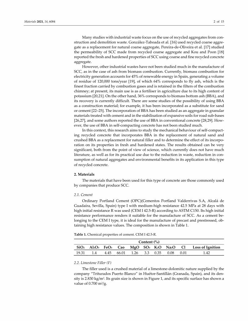
sity is 2.830 kg/m3. Its grain size is shown in Figure 1, and its specific surface has shown a
value of 0.700 m2/g.
Materials 2021, 14, 6084 3 of 15
Figure 1. Particle size distribution curve.
2.3. Natural Sand (NS)
The sand is of a limestone‐dolomitic nature and is practically free of fines. It comes
from the El Rayo quarry, Hermanos Guerrero, Loja (Granada, Spain).
2.4. Natural Coarse Gravel (NCG) and Natural Medium Gravel (NMG)
The aggregates used in the manufacture of concrete have a maximum size of 16 mm,
the main properties are shown in Table 2 (Standards used in the experimental work are
shown in Appendix A), and their granulometries are shown in Figure 1. The total gravel
has been obtained by mixing 4/8 mm medium gravel (NMG) and 8/16 mm coarse gravel
(NCG) from the Quintos quarry located in Huétor‐Santillán (Granada).
Table 2. Physical and chemical properties of natural aggregates and BBA.
PROPERTIES NS NCG NMG BBA Test Method
Density‐SSD (kg/m3) 2.53 2.65 2.62 1.73 EN 1097‐6: 2014
Water absorption (%) 0.9 1.59 1.63 19.83 EN 1097‐6:2014
Los Angeles (%) ‐ 17 18
Friability ratio (%) ‐ 31.8 146404: 2018
Sand equivalent (%) 85 ‐ ‐ 23 EN 933‐8:2012
Plasticity Non plastic Non plastic Non plastic Non plastic EN ISO 17892‐12:2019
Chlorides 0.15 EN 1774‐1:2010
Organic matter % 1.51 UNE 103204:2019
Water‐soluble sulphate (%SO4) <0.01 <0.01 <0.01 0.32 EN 1744‐1:2010
Acid‐soluble sulphate (%SO4) <0.01 <0.01 <0.01 0.33 EN 1744‐1:2010
Elemental content (%) EN 196‐2:2014
SiO2 ‐ ‐ ‐ 37.67
CaO ‐ ‐ ‐ 22.03
K2O ‐ ‐ ‐ 14.06
MgO ‐ ‐ ‐ 5.95
Fe2O3 ‐ ‐ ‐ 2.52
Al2O3 ‐ ‐ ‐ 3.02
0.0
10.0
20.0
30.0
40.0
50.0
60.0
70.0
80.0
90.0
100.0
0.1 1 10 100
% Pasing
Particle size (mm)
Filler
NS
NMG
NCG
Materials 2021, 14, 6084 4 of 15
2.5. Biomass Bottom Ash (BBA)
This is the coarse fraction produced in the primary combustion chamber due to in‐
complete combustion (decrease in the melting point) and is made up of most of the min‐
eral fraction of the original biomass [30]. The BBA comes from the biomass power plant
called Bioeléctrica de Linares S.L. from the company Sacyr Industrial located in the Lina‐
res‐Baeza station, Jaén, Spain.
The fuel supply of the biomass used for the generation of electricity is made up of
approximately 40% olive cake and 60% biomass of wood (olive, pine and eucalyptus). The
BBAs were processed in the laboratory to obtain two different materials used in the man‐
ufacture of SCC: BBA (biomass bottom ash kiln‐dried for 24 h and sieved with a particle
size no larger than 5 mm) and BBA‐C (biomass ash kiln‐dried for 24 h and crushed, with
a particle size no larger than 0.25 mm). The physical and chemical properties of BBA are
presented in Table 2.
The physical and chemical characteristics of BBA depend on the types and the differ‐
ent burned biomass used as fuel, in addition to the technology used in the electricity gen‐
eration plant by burning biomass [31,32].
An important factor in the physical properties of BBAs is their high absorption and
low density (19.83% and 1.73 g/cm3, respectively). Both parameters are important in the
design of mixtures, where the presence of water and the volume of the material are con‐
ditioning factors for its manufacture [33].
The friability ratio is an important property from an engineering point of view. A
friable material is characterised by the ease of fragmentation of its particles [34]. The BBA
has a high coefficient of friability (31.8%), but according to the technical specifications
(EHE‐08) a coefficient lower than 40% is recommended for the manufacture of concrete,
so the BBAs under study are suitable for manufacturing concrete.
The organic matter content in the BBA has shown to be a consequence of the effi‐
ciency of the biomass combustion plant [35]; according to other authors, the BBA sample
does not present a high percentage of organic content matter [31,32].
Calcium was the main constituent and accounted for 22.03% by weight (as oxide) of
the ash mass. In addition to calcium, BBA is characterised by the relatively high content
of potassium (14.06% by weight), the presence of which resulted from the initial content
of nutrient ingredients in the olive wood trimmings, in accordance with previous studies
[36].
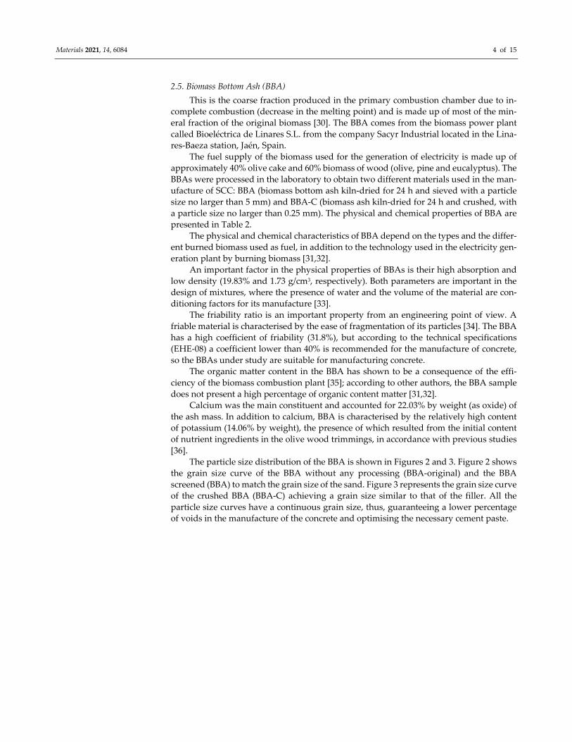
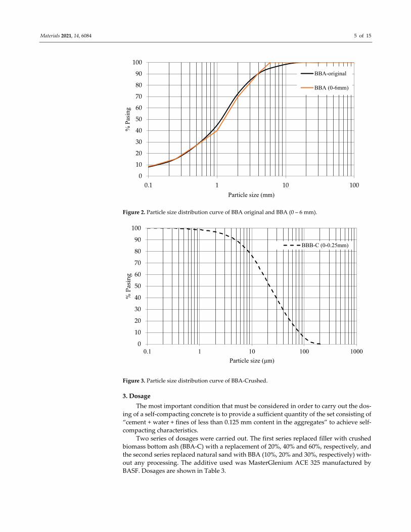
The particle size distribution of the BBA is shown in Figures 2 and 3. Figure 2 shows
the grain size curve of the BBA without any processing (BBA‐original) and the BBA
screened (BBA) to match the grain size of the sand. Figure 3 represents the grain size curve
of the crushed BBA (BBA‐C) achieving a grain size similar to that of the filler. All the
particle size curves have a continuous grain size, thus, guaranteeing a lower percentage
of voids in the manufacture of the concrete and optimising the necessary cement paste.
Materials 2021, 14, 6084 5 of 15
Figure 2. Particle size distribution curve of BBA original and BBA (0 – 6 mm).
Figure 3. Particle size distribution curve of BBA‐Crushed.
3. Dosage
The most important condition that must be considered in order to carry out the dos‐
ing of a self‐compacting concrete is to provide a sufficient quantity of the set consisting of
“cement + water + fines of less than 0.125 mm content in the aggregates” to achieve self‐
compacting characteristics.
Two series of dosages were carried out. The first series replaced filler with crushed
biomass bottom ash (BBA‐C) with a replacement of 20%, 40% and 60%, respectively, and
the second series replaced natural sand with BBA (10%, 20% and 30%, respectively) with‐
out any processing. The additive used was MasterGlenium ACE 325 manufactured by
BASF. Dosages are shown in Table 3.
0
10
20
30
40
50
60
70
80
90
100
0.1 1 10 100
% P
asin
g
Particle size (mm)
BBA-original
BBA (0-6mm)
0
10
20
30
40
50
60
70
80
90
100
0.1 1 10 100 1000
% Pasing
Particle size (μm)
BBB-C (0-0.25mm)
Materials 2021, 14, 6084 6 of 15
Table 3. Concrete mix proportions (kg/m3).
Serie Mix Name Natural Aggregates
Biomass Bottom
Ash CEM Water W/C Rela‐
tion Additive
NCG NMG NS Filler BBA‐C BBA CONTROL 487.62 151.1 989.3 185 ‐ ‐
400
200 0.5 3.6
SERIE 1‐
SSC‐BBAc
S1‐SSC‐
20BBA‐C 487.62 151.1 989.3 148 37 ‐ 200 0.5 4.8
S1‐SSC‐
40BBA‐C 487.62 151.1 989.3 111 74 ‐ 200 0.5 8.0
S1‐SSC‐
60BBA‐C 487.62 151.1 989.3 74 111 ‐ 200 0.5 8.4
SERIE 2‐
SSC‐BBA
S2‐SSC‐
10BBA 487.62 151.1 890.67 185 ‐ 98.63
400
200 0.5 4.8
S2‐SSC‐
20BBA 487.62 151.1 791.44 185 ‐ 197.86 200 0.5 6.8
S2‐SSC‐
30BBA 487.62 151.1 692.51 185 ‐ 296.79 200 0.5 7.0
3.1. Workability of the Fresh Concrete
All the mixtures that underwent the tests indicated the current regulations (EHE‐08)
for the characterisation of self‐compatibility: slump flow, according to EN 12350‐8; V‐fun‐
nel according to EN 12350‐9; J‐Ring according to EN 12350‐12; and L‐Box test according
to EN 12350‐10.
Slump flow: This is the simplest and most widely used method due to the simplicity
of the equipment required. The value of the flow extension (Df) is useful for evaluating
the deformation capacity of self‐compacting concrete. Df measurements resulting be‐
tween 60 and 80 cm are recommended, presenting mixtures in that range with good ability
or ease for filling, according to EFNARC, 2002 [37].
J‐Ring: This determines the ability of self‐compacting concrete to flow through nar‐
row openings, including gaps between trusses and other obstructions without segregation
or blockage. After flow ceases, the final extension diameter is measured as the mean of
two perpendicular diameters.
L‐Box: This consists of a vertical tank that connects to a horizontal channel through
an opening in which reinforcement bars are placed. The test involves filling the reservoir
and allowing concrete to flow into the channel through the trusses. The time taken for the
concrete to reach a distance of 200 mm (T20) and 400 mm (T40) is determined, and the
heights H1 and H2 are reached at both ends of the horizontal part, with the mixture al‐
ready at rest. The H2/H1 ratio is defined as the blocking coefficient (Cb).
V‐funnel: This test evaluates the ability of concrete to flow in restricted areas in a
vertical direction and under its own weight, qualifying the tendency with respect to seg‐
regation and blocking, by observing the variation in flow velocity.
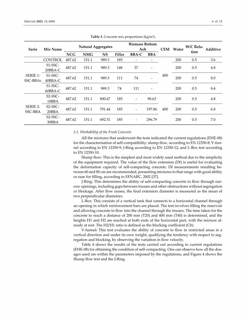
Table 4 shows the results of the tests carried out according to current regulations
(EHE‐08) for obtaining the condition of self‐compacting. One can observe how all the dos‐
ages used are within the parameters imposed by the regulations, and Figure 4 shows the
Slump flow test and the J‐Ring
Materials 2021, 14, 6084 7 of 15
(a) (b)
Figure 4. Results of the tests carried out according to the current regulations for considering self‐compacting concrete
(EHE‐08). Slump flow (a) and J‐Ring (b).
Table 4. Results of the tests carried out according to the current regulations for considering self‐compacting concrete (EHE‐08).
Test Measured Parameter Test Result Permissible Range (EHE‐08)
SSC‐Control
Slump flow T50 (s) 2.8
df (mm) 690
J‐Ring djf (mm) 650
L‐Box Cb 0.78
V‐funnel Tv (s) 5.02
SSC‐20BBA‐C
Slump flow T50 (s) 1.5
df (mm) 650
J‐Ring djf (mm) 650
L‐Box Cb 0.75
V‐funnel Tv (s) 4.6
SSC‐40BBA‐C
Slump flow T50 (s) 1.6
df (mm) 660
J‐Ring djf (mm) 670
L‐Box Cb 0.78
V‐funnel Tv (s) 5.9
SSC‐60BBA‐C
Slump flow T50 (s) 2.1 T50 ≤ 8 s (s)
df (mm) 760 550 mm ≤ df ≤ 850 mm
J‐Ring djf (mm) 740 ≥df‐50 mm
L‐Box Cb 0.75 0.75 ≤ Cb ≤ 1.00
V‐funnel Tv (s) 7.9 4 s ≤ Tv ≤ 20 s
SSC‐10BBA
Slump flow T50 (s) 3.6
df (mm) 660
J‐Ring djf (mm) 610
L‐Box Cb 0.79
V‐funnel Tv (s) 10
SSC‐20BBA Slump flow T50 (s) 4
df (mm) 690
Materials 2021, 14, 6084 8 of 15
J‐Ring djf (mm) 650
L‐Box CbL 0.8
V‐funnel Tv (s) 10
SSC‐30BBA
Slump flow T50 (s) 4.3
df (mm) 640
J‐Ring djf (mm) 630
L‐Box CbL 0.81
V‐funnel Tv (s) 11
4. Experimental Methods and Results
4.1. Compressive Strength of Test Specimens
The compressive strength was determined on 100 mm × 100 mm cubic samples for
ages 7, 28, 90 and 256 days according to EN 12390‐3: 2019. Table 5 shows the values of the
resistances obtained for each of the series.
Table 5. Compressive strength of SCC.
Compressive Strength (MPa)
Time (Days) 7 28 90 256 INCREASING
28–256 DAYS (%) CONTROL 67.26 81.53 82.87 83.14 1.90
SERIE 1‐SSC‐
BBA‐C
S1‐SSC‐20BBA‐
C 53.06 59.62 65.76 72.43 21.48
S1‐SSC‐40BBA‐
C 43.11 51.93 56.69 64.81 24.80
S1‐SSC‐60BBA‐
C 38.74 45.21 49.12 58.67 29.77
SERIE 2‐SSC‐
BBA
S2‐SSC‐10BBA 43.29 50.12 53.28 58.44 16.60
S2‐SSC‐20BBA 37.76 43.51 47.96 51.27 17.83
S2‐SSC‐30BBA 35.58 39.48 43.55 48.94 23.96
The use of industrial by‐products as a substitute for the fine fraction directly affects
simple compressive strength [38]. Some authors focus on the substitution of coarse and
fine fraction of natural aggregates, obtaining substitution ranges depending on the type
of industrial by‐product used [39].
In this work, ranges of 20%, 40% and 60% substitution of limestone filler by BBA‐C
(Series 1) and 10%, 20% and 30% substitution of natural sand (Series 2) were proposed.
The best compressive strength results were shown for Series 1 where lime filler was
replaced by BBA‐C, which is essential to avoid SCC segregation.
The analysis of the 28 day compressive strength showed a reduction in all mixes com‐
bined with biomass bottom ash, a result also observed by Mehta and Monteiro and
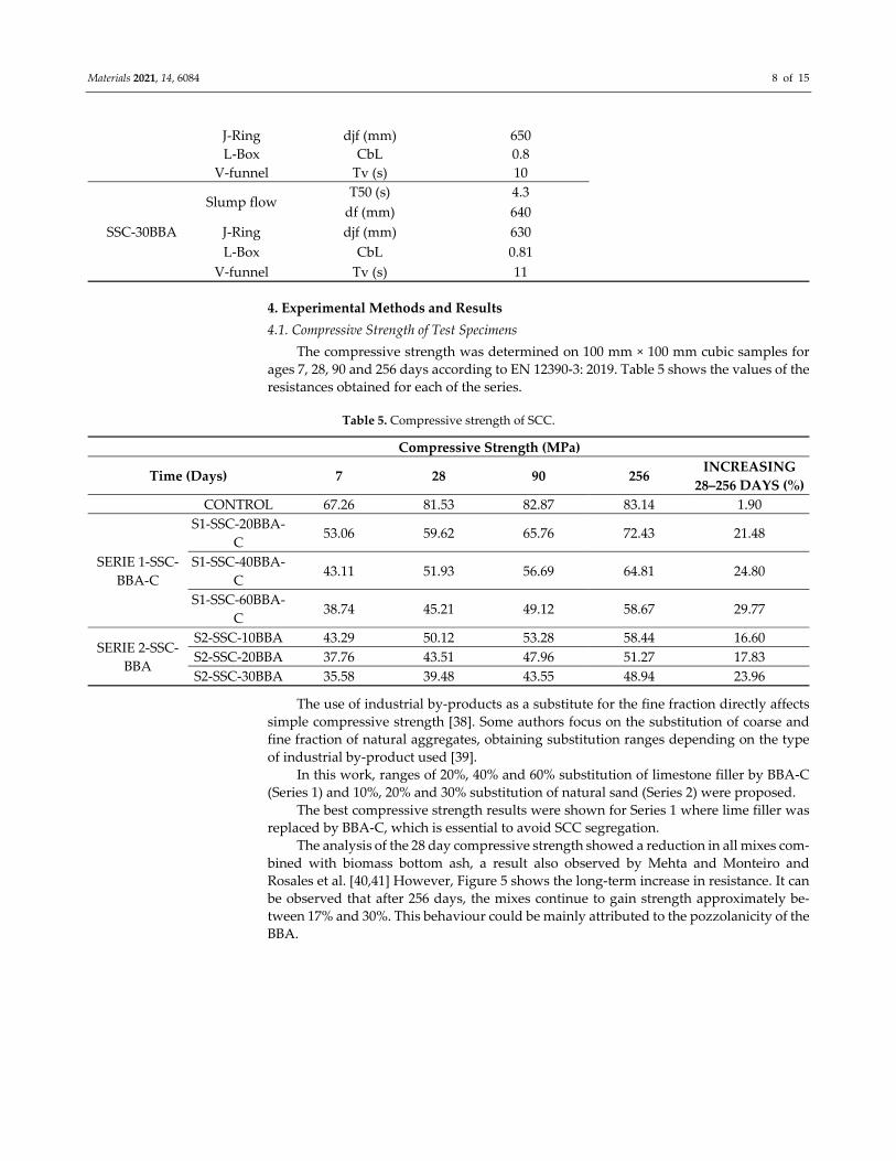
Rosales et al. [40,41] However, Figure 5 shows the long‐term increase in resistance. It can
be observed that after 256 days, the mixes continue to gain strength approximately be‐
tween 17% and 30%. This behaviour could be mainly attributed to the pozzolanicity of the
BBA.
Materials 2021, 14, 6084 9 of 15
Figure 5. Comparative of increase in compressive strength from 28 to 256 days.
4.2. Tensile Splitting Strength of Test Specimens
This test was carried out by subjecting a 150 × 300 mm cylindrical specimen cured in
a humid chamber for diametric compression for 28 days in accordance with EN 12390‐6:
2009. A load was applied evenly along two opposite lines until breakage was achieved.
This load causes a relatively uniform tensile stress throughout the diameter of the vertical
load plane, and this tension is the one that exhausts the specimen and triggers the break
in the diametral plane. The values obtained are shown in Table 6.
Table 6. Tensile splitting strength and modulus of elasticity.
SERIE 1‐SSC‐BBA‐C SERIE 2‐SSC‐BBA
CONTROL S1‐SSC‐
20BBA‐C
S1‐SSC‐
40BBA‐C
S1‐SSC‐
60BBA‐C
S2‐SSC‐
10BBA
S2‐SSC‐
20BBA
S2‐SSC‐
30BBA
Tensile splitting strength
(MPa) 8.56 6.08 5.18 4.15 4.46 3.65 3.15
Modulus of elasticity (MPa) 56,129 42,018 36,947 31,779 35,439 30,857 28,541
4.3. Determination of Modulus of Elasticity
The modulus of elasticity of concrete represents the stiffness of this material when
faced with a load imposed on it. The test for the determination of the static modulus of
elasticity of concrete is carried out by means of the EN 12390‐13: 2014 Standard and has
as its principle the application of static load and the corresponding produced unit defor‐
mation.
The first phase (elastic zone) applied a stress of 30% of the compressive strength ob‐
tained in the previously described test. In the second phase (curved line), the concrete
specimen is submitted to breakage according to the regulations. The results are shown in
Table 6.
Regarding the tensile splitting strength, the trend of the experimental data tends to
guarantee the existing relationship between compression and traction in concrete. Tensile
splitting strength values were observed in the concrete representing approximately 10–
15% of the results obtained for compressive strength.
05101520253035
CONTROL
S1‐SSC‐20B
BA‐C
S1‐SSC‐40B
BA‐C
S1‐SSC‐60B
BA‐C
S2‐SSC‐10B
BA
S2‐SSC‐20B
BA
S2‐SSC‐30B
BA
SERIE 1‐SSC‐BBAc SERIE 2‐SSC‐BBAc
%
Increase in compressive strength
from 28 to 256 days
Materials 2021, 14, 6084 10 of 15
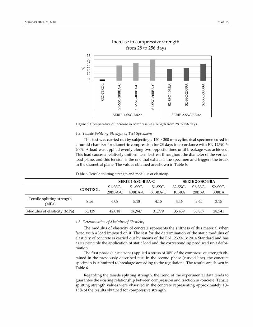
In order to observe the relationship between tensile splitting strength and the mod‐
ulus of elasticity, a trend is proposed which aims to observe the behaviour of these two
variables (Figure 6).
The modulus of elasticity ranged from 42.01 GPa to 31.77 GPa for Series 1 and be‐
tween 35.43 GPa and 28.54 GPa for Series 2. These results demonstrate that the manufac‐
tured concrete can be suitable for many structural applications, even for structures with
demanding limitations regarding serviceability limit states (e.g., deformations and deflec‐
tions) [42].
Figure 6. Relationship between tensile splitting strength and modulus of elasticity.
4.4. Density and Absorption of Hardened Concrete
The density and absorption percentage were determined in specimens of hardened
SCC. Each series was subjected to a cycle of immersion in water for 24 h and subsequently
to oven drying between 105 °C and 110 °C for 24 h. With this procedure, the apparent
mass in the water, the saturated mass with a dry surface and the dry mass are obtained,
and the density and supply are obtained with these data in accordance with the EN 12390‐
7: 2019 standard (Testing hardened concrete—Part 7: Density of hardened concrete). The
test results are shown in Table 7.
Table 7. Density and absorption of hardened concrete.
SERIE 1‐SSC‐BBA‐C SERIE 2‐SSC‐BBA
CONTROL S1‐SSC‐
20BBA‐C
S1‐SSC‐
40BBA‐C
S1‐SSC‐
60BBA‐C
S2‐SSC‐
10BBA
S2‐SSC‐
20BBA
S2‐SSC‐
30BBA
Density (Kg/dm3) 2.46 2.44 2.41 2.38 2.39 2.35 2.33
Absorption (%) 5.74 6.22 6.39 6.8 7.12 7.48 7.92
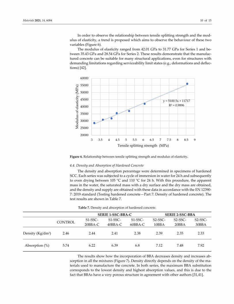
The results show how the incorporation of BBA decreases density and increases ab‐
sorption in all the mixtures (Figure 7). Density directly depends on the density of the ma‐
terials used to manufacture the concrete. In both series, the maximum BBA substitution
corresponds to the lowest density and highest absorption values, and this is due to the
fact that BBAs have a very porous structure in agreement with other authors [31,41].
y = 5100.5x + 11717
R² = 0.9896
20000
25000
30000
35000
40000
45000
50000
55000
60000
3 3.5 4 4.5 5 5.5 6 6.5 7 7.5 8 8.5 9
Modulus of elasticity (MPa)
Tensile splitting strength (MPa)
Materials 2021, 14, 6084 11 of 15
Figure 7. Relationship between density and absorption.
4.5. Penetration of Water under Pressure
The depth of water penetration under pressure was determined in 150 × 300 mm cy‐
lindrical specimens cured in a humidity chamber for 28 days. The water was applied un‐
der pressure of 500 kPa for 72 h. Subsequently, the test piece was divided by breaking it
into two halves, and the penetration of the waterfront was recorded in accordance with
the EN 12390‐8:2019 standard. The results are shown in Table 8.
Table 8. Penetration of water under pressure (mm).
SERIE 1‐SSC‐BBA‐C SERIE 2‐SSC‐BBA
CONTROL S1‐SSC‐
20BBA‐C
S1‐SSC‐
40BBA‐C
S1‐SSC‐
60BBA‐C
S2‐SSC‐
10BBA
S2‐SSC‐
20BBA
S2‐SSC‐
30BBA
Penetration of water under
pressure (mm) 3.12 5.37 6.89 7.54 6.57 8.15 9.87
Structural Concrete Instruction (EHE08) uses the determination of water penetration
depth as a verifier that the concrete has sufficient impermeability to ensure durability
during the service life of the structure.
The limits of the Structural Concrete Instruction are set at 50 mm for maximum depth
and 30 mm for the average depth in mass or reinforced concrete.
As shown in Table 8, the differently manufactured concrete did not exceed the estab‐
lished limits. The higher water penetration values correspond to the higher BBA replace‐
ment rate, mainly due to the high porosity of the BBA [26].
4.6. Carbonatation Depth
Carbonation is a process of chemical origin that consists of the combination of CO2
with concrete portlandite. In order to know the degree of carbonation, the specimens were
subjected to a CO2 saturated environment according to UNE 112011:2011 (relative humid‐
ity 55–65%, a temperature of 23 ± 3 °C and an air supply with 5 ± 0.1% CO2). To carry out
the test, a piece of concrete was broken from each of the specimens, then the phenolphtha‐
lein solution was applied to the concrete. A colour change (pink) on the application sur‐
face will indicate that the concrete is not carbonated. If the colouration does not occur, it
means that it is an area that is already carbonated.
y = ‐15.889x + 44.852
R² = 0.9501
0
1
2
3
4
5
6
7
8
9
2.32 2.34 2.36 2.38 2.4 2.42 2.44 2.46 2.48
Absorption (%)
Density (Kg/dm3)
Materials 2021, 14, 6084 12 of 15
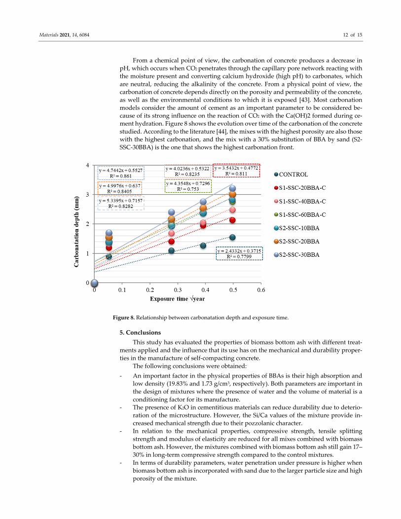
From a chemical point of view, the carbonation of concrete produces a decrease in
pH, which occurs when CO2 penetrates through the capillary pore network reacting with
the moisture present and converting calcium hydroxide (high pH) to carbonates, which
are neutral, reducing the alkalinity of the concrete. From a physical point of view, the
carbonation of concrete depends directly on the porosity and permeability of the concrete,
as well as the environmental conditions to which it is exposed [43]. Most carbonation
models consider the amount of cement as an important parameter to be considered be‐
cause of its strong influence on the reaction of CO2 with the Ca(OH)2 formed during ce‐
ment hydration. Figure 8 shows the evolution over time of the carbonation of the concrete
studied. According to the literature [44], the mixes with the highest porosity are also those
with the highest carbonation, and the mix with a 30% substitution of BBA by sand (S2‐
SSC‐30BBA) is the one that shows the highest carbonation front.
Figure 8. Relationship between carbonatation depth and exposure time.
5. Conclusions
This study has evaluated the properties of biomass bottom ash with different treat‐
ments applied and the influence that its use has on the mechanical and durability proper‐
ties in the manufacture of self‐compacting concrete.
The following conclusions were obtained:
‐ An important factor in the physical properties of BBAs is their high absorption and
low density (19.83% and 1.73 g/cm3, respectively). Both parameters are important in
the design of mixtures where the presence of water and the volume of material is a
conditioning factor for its manufacture.
‐ The presence of K2O in cementitious materials can reduce durability due to deterio‐
ration of the microstructure. However, the Si/Ca values of the mixture provide in‐
creased mechanical strength due to their pozzolanic character.
‐ In relation to the mechanical properties, compressive strength, tensile splitting
strength and modulus of elasticity are reduced for all mixes combined with biomass
bottom ash. However, the mixtures combined with biomass bottom ash still gain 17–
30% in long‐term compressive strength compared to the control mixtures.
‐ In terms of durability parameters, water penetration under pressure is higher when
biomass bottom ash is incorporated with sand due to the larger particle size and high
porosity of the mixture.
Materials 2021, 14, 6084 13 of 15
‐ The depth of carbonation of concrete depends on many variables, and the most im‐
portant ones are porosity and permeability. Mixtures with higher porosity and per‐
meability are also those with higher carbonation.
In conclusion, the use of self‐compacting concretes with the substitution of up to 30%
of natural sand by screened BBA and up to 60% of filler by crushed BBA is recommended
for use in civil infrastructure works. The valorisation of biomass bottom ash instead of
exploiting natural or non‐renewable resources can eliminate the negative impact associ‐
ated with indiscriminate disposal of this by‐product in landfills.
Author Contributions: Conceptualization, M.C. and F.A.; methodology, M.L.‐A. and M.M.‐E.; for‐
mal analysis, J.R and M.C.; investigation, M.C., M.L.‐A. and M.M.‐E.; resources, F.A. and M.C.; data
curation, J.R. and M.C.; writing—original draft preparation, M.C.; writing—review and editing, J.R.
and M.C.; visualization, F.A. and M.M.‐E.; supervision, M.C.; project administration, F.A. All au‐
thors have read and agreed to the published version of the manuscript.
Funding: FEDER/ Ministry of Science, Innovation and Universities—Agencia Estatal de Investi‐
gación (State Research Agency)/Valorisation of biomass bottom ash for sustainable construction ap‐
plications (1264457‐R)—BIOCEM
Acknowledgments: The authors would like to thank Professor José Rodriguez Montero for sharing
all his knowledge, time and work.
Conflicts of Interest: The authors declare no conflicts of interest.
Appendix A
Standards used in the experimental work are as follows:
EN 1097‐6:2014. Tests for mechanical and physical properties of aggregates—Part 6:
Determination of particle density and water absorption
EN 146404: 2018. Aggregates for concrete determination of the coefficient of friability
of the sands.
EN 933‐8:2012. Tests for geometrical properties of aggregates—Part 8: Assessment of
fines—Sand equivalent test.
EN ISO 17892‐12:2019. Geotechnical investigation and testing—Laboratory testing of
soil—Part 12: Determination of liquid and plastic limits (ISO 17892‐12:2018).
EN 1744‐1:2010. Tests for chemical properties of aggregates—Part 1: Chemical anal‐
ysis.
UNE 103204:2019. Organic matter content of a soil by the potassium permanganate
method.
UNE ‐EN 196‐2:2014. Method of testing cement—Part 2: Chemical analysis of cement.
Real Decreto 1247/2008, de 18 de julio, por el que se aprueba la instrucción de hormi‐
gón estructural (EHE‐08), Boletín Oficial del Estado, núm. 203, de 22 de agosto de 2008,
pp. 35176 a 35178.
UNE‐EN 12350‐8:2011. Testing fresh concrete—Part 8: Self‐compacting concrete—
Slump‐flow test.
UNE‐EN 12350‐9:2011. Testing fresh concrete—Part 9: Self‐compacting concrete—V‐
funnel test.
UNE‐EN 12350‐10:2011. Testing fresh concrete—Part 10: Self‐compacting concrete—
L box test.
UNE 12350‐12:2011. Testing fresh concrete—Part 12: Self‐compacting concrete—J‐
ring test.
UNE 12390‐3:2019. Testing hardened concrete—Part 3: Compressive strength of test
specimens.
UNE 12390‐6:2010. Testing hardened concrete—Part 6: Tensile splitting strength of
test specimens.
EN 12390‐13:2014. Testing hardened concrete—Part 13: Determination of secant
modulus of elasticity in compression
EN 12390‐7:2019. Testing hardened concrete—Part 7: Density of hardened concrete.

Materials 2021, 14, 6084 14 of 15
EN 12390‐8:2019. Testing hardened concrete—Part 8: Depth of penetration of water
under pressure
UNE 112011:2011. Corrosion of concrete reinforcement steel. Determination of the
carbonatation depth for in‐service concrete.
References
1. Okamura, H. Self‐compacting high‐performance concrete. Concr. Int. 1997, 19, 50–54.
2. Khayat, K.H. Use of Self‐Consolidating Concrete in Canada. In Proceedings of the International Workshop on Self‐Compacting
Concrete, Kochi, Japan, 23–26 August 1998; Volume 23, p. 26.
3. Ernst, F.M.L. Onderzoek Zelfverdichtend Beton. MSc Thesis, TUE/CCO/00‐09, Eindhoven University of Technology, Faculteit
Bouwkunde, Capaciteitsgroep Constructief Ontwerpen, Eindhoven, The Netherlands, 2000. (In Dutch).
4. Su, N.; Hsu, K.C.; Chai, H.W. A simple mix design method for self‐compacting concrete. Cement Concr. Res. 2001, 31, 1799–1807.
5. Langley, W.S.; Carette, G.G.; Malhotra, V.M. Structural concrete incorporating high volumes of ASTM class fly ash. Mater. J.
1989, 86, 507–514.
6. Li, G.; Zhao, X. Properties of concrete incorporating fly ash and ground granulated blast‐furnace slag. Cement Concr. Compos.
2003, 25, 293–299.
7. Li, G. Properties of high‐volume fly ash concrete incorporating nano‐SiO2. Cement Concr. Res. 2004, 34, 1043–1049.
8. Sabet, F.A.; Libre, N.A.; Shekarchi, M. Mechanical and durability properties of self‐consolidating high performance concrete
incorporating natural zeolite, silica fume and fly ash. Constr. Build. Mater. 2013, 44, 175–184.
9. Patil, B.B.; Kumbhar, P.D. Strength and durability properties of high performance concrete incorporating high reactivity me‐
takaolin. Int. J. Mod. Eng. Res. 2012, 2, 1099–1104.
10. Persson, B. A comparison between mechanical properties of self‐compacting concrete and the corresponding properties of nor‐
mal concrete. Cement Concr. Res. 2001, 31, 193–198.
11. Mebrouki, A.; Belas, N.; Bendani, K.; Bouhamou, N. A self‐compacting cement paste formulation using mixture design. J. Appl.
Sci. 2009, 9, 4127–4136.
12. Concha, N.C.; Calilung, M.G.V. (2017, December). Investigation on the effects of blended admixtures on workability of self‐
compacting concrete. In Proceedings of the 2017 IEEE 9th International Conference on Humanoid, Nanotechnology, Infor‐
mation Technology, Communication and Control, Environment and Management (HNICEM), Manila, Philippines, 1–3 Decem‐
ber 2017; pp. 1–6.
13. Bignozzi, M.C.; Sandrolini, F. Tyre rubber waste recycling in self‐compacting concrete. Cement Concr. Res. 2006, 36, 735–739.
14. Ali, E.E.; Al‐Tersawy, S.H. Recycled glass as a partial replacement for fine aggregate in self compacting concrete. Constr. Build.
Mater. 2012, 35, 785–791.
15. Ghernouti, Y.; Rabehi, B.; Bouziani, T.; Ghezraoui, H.; Makhloufi, A. Fresh and hardened properties of self‐compacting concrete
containing plastic bag waste fibers (WFSCC). Constr. Build. Mater. 2015, 82, 89–100.
16. González‐Taboada, I.; González‐Fonteboa, B.; Martínez‐Abella, F.; Seara‐Paz, S. Analysis of rheological behaviour of self‐com‐
pacting concrete made with recycled aggregates. Constr. Build. Mater. 2017, 157, 18–25.
17. Pereira‐de‐Oliveira, L.A.; Nepomuceno, M.C.S.; Castro‐Gomes, J.P.; Vila, M.D.F.C. Permeability properties of self‐compacting
concrete with coarse recycled aggregates. Constr. Build. Mater. 2014, 51, 113–120.
18. Kou, S.C.; Poon, C.S. Properties of self‐compacting concrete prepared with coarse and fine recycled concrete aggregates. Cement
Concr. Compos. 2009, 31, 622–627.
19. Calvo, J.G.; Hidalgo, A.; Alonso, M.C.; Luxán, M.P.; Luco, L.F. Caracterización de residuos procedentes de los procesos de
combustión de biomasa. viabilidad de uso como materiales de construcción. In Proceedings of the XI Congreso Nacional de
Materiales Zaragoza, Zaragoza, Spain, 23–25 June 2010.
20. Nogales, R.; Delgado, G.; Quirantes, M.; Romero, M.; Romero, E.; Molina‐Alcaide, E. Characterization of olive waste ashes as
fertilizers. In Recycling of Biomass Ashes; Springer: Berlin, Heidelberg, Germany, 2011; pp. 57–68.
21. Omil, B.; Sánchez‐Rodríguez, F.; Merino, A. Effects of ash applications on soil status, nutrition, and growth of Pinus radiata D.
Don Plantations. In Recycling of Biomass Ashes; Springer: Berlin, Heidelberg, Germany, 2011; pp. 69–86.
22. Maschio, S.; Tonello, G.; Piani, L.; Furlani, E. Fly and bottom ashes from biomass combustion as cement replacing components
in mortars production: Rheological behaviour of the pastes and materials compression strength. Chemosphere 2011, 85, 666–671.
23. Modolo, R.C.E.; Ferreira, V.M.; Tarelho, L.A.; Labrincha, J.A.; Senff, L.; Silva, L. Mortar formulations with bottom ash from
biomass combustion. Constr. Build. Mater. 2013, 45, 275–281.
24. Beltrán, M.G.; Barbudo, A.; Agrela, F.; Jiménez, J.R.; de Brito, J. Mechanical performance of bedding mortars made with olive
biomass bottom ash. Constr. Build. Mater. 2016, 112, 699–707.
25. Rosales, J.; Cabrera, M.; Beltrán, M.G.; López, M.; Agrela, F. Effects of treatments on biomass bottom ash applied to the manu‐
facture of cement mortars. J. Clean. Prod. 2017, 154, 424–435.
26. Cabrera, M.; Agrela, F.; Ayuso, J.; Galvin, A.P.; Rosales, J. Feasible use of biomass bottom ash in the manufacture of cement
treated recycled materials. Mater. Struct. 2016, 49, 3227–3238.
27. Cabrera, M.; Rosales, J.; Ayuso, J.; Estaire, J.; Agrela, F. Feasibility of using olive biomass bottom ash in the sub‐bases of roads
and rural paths. Constr. Build. Mater. 2018, 181, 266–275.
Materials 2021, 14, 6084 15 of 15
28. Beltrán, M.G.; Agrela, F.; Barbudo, A.; Ayuso, J.; Ramírez, A. Mechanical and durability properties of concretes manufactured
with biomass bottom ash and recycled coarse aggregates. Constr. Build. Mater. 2014, 72, 231–238.
29. Agrela, F.; Beltran, M.G.; Cabrera, M.; López, M.; Rosales, J.; Ayuso, J. Properties of recycled concrete manufacturing with all‐
in recycled aggregates and processed biomass bottom ash. Waste Biomass Valoriz. 2018, 9, 1247–1259.
30. Khan, A.A.; De Jong, W.; Jansens, P.J.; Spliethoff, H. Biomass combustion in fluidized bed boilers: Potential problems and rem‐
edies. Fuel Process. Technol. 2009, 90, 21–50.
31. Cabrera, M.; Galvin, A.P.; Agrela, F.; Carvajal, M.D.; Ayuso, J. Characterisation and technical feasibility of using biomass bottom
ash for civil infrastructures. Constr. Build. Mater. 2014, 58, 234–244.
32. Hinojosa, M.J.R.; Galvín, A.P.; Agrela, F.; Perianes, M.; Barbudo, A. Potential use of biomass bottom ash as alternative construc‐
tion material: Conflictive chemical parameters according to technical regulations. Fuel 2014, 128, 248–259.
33. Melotti, R.; Santagata, E.; Bassani, M.; Salvo, M.; Rizzo, S. A preliminary investigation into the physical and chemical properties
of biomass ashes used as aggregate fillers for bituminous mixtures. Waste Manag.2013, 33, 1906–1917.
34. Munkholm, L.J. Soil friability: A review of the concept, assessment and effects of soil properties and management. Geoderma
2011, 167, 236–246.
35. Huang, Y.; McMullan, J.T.; Williams, B.C. Influences of coal type on the performance of a pressurised fluidised bed combustion
power plant. Fuel 2000, 79, 1595–1601.
36. Modolo, R.C.E.; Silva, T.; Senff, L.; Tarelho, L.A.C.; Labrincha, J.A.; Ferreira, V.M.; Silva, L. Bottom ash from biomass combustion
in BFB and its use in adhesive‐mortars. Fuel Process. Technol. 2015, 129, 192–202.
37. Efnarc, S. Guidelines for Self‐Compacting Concrete; Association House: London, UK, 2002; Volume 32, p. 34.
38. Corinaldesi, V.; Moriconi, G. Influence of mineral additions on the performance of 100% recycled aggregate concrete. Constr.
Build. Mater. 2009, 23, 2869–2876.
39. Tiwari, A.; Singh, S.; Nagar, R. Feasibility assessment for partial replacement of fine aggregate to attain cleaner production
perspective in concrete: A review. J. Clean. Prod. 2016, 135, 490–507.
40. Mehta, P.K.; Monteiro, P.J.; Concrete‐Microstructure, P. Materials; Mc Graw Hill: New York, NY, USA, 2006; pp. 85–86.
41. Rosales, J.; Beltrán, M.G.; Cabrera, M.; Velasco, A.; Agrela, F. Feasible use of biomass bottom ash as addition in the manufacture
of lightweight recycled concrete. Waste Biomass Valorize. 2016, 7, 953–963.
42. Skarendahl, Å.; Petersson, Ö. (Eds.) Report 23: Self‐Compacting Concrete–State‐of‐the‐Art Report of Rilem Technical Committee 174‐
SCC; RILEM Publications: Moscow, Russia, 2000; Volume 23.
43. Bertolini, L.; Elsener, B.; Pedeferri, P.; Redaelli, E.; Polder, R.B. Corrosion of Steel in Concrete: Prevention, Diagnosis, Repair; John
Wiley & Sons: Hoboken, NJ, USA, 2013.
44. Rosales, J.; Agrela, F.; Díaz‐López, J.L.; Cabrera, M. Alkali‐Activated Stainless Steel Slag as a Cementitious Material in the Man‐
ufacture of Self‐Compacting Concrete. Materials 2021, 14 (14), 3945.


![Recycled Aggregate Self Compacting Concrete - IJMTER · Int ernational Journal of Modern Trends in Engineering and Research (IJMTER) Volume 02, Issue 02, [February - 2015] e -ISSN:](https://img.pdfslide.us/doc/110x75/5ac676a87f8b9a220b8deefc/recycled-aggregate-self-compacting-concrete-ijmter-ernational-journal-of-modern.jpg)