Embed Size (px)
Citation preview

Article
Effect of Aluminum and Silicon on Formation Fe-Al-Si Intermetallic Phase Microstructure and Wear Resistance of Gray Cast Iron 1E. Sanatizadeh1, 2Amir Kordijazi, *1Sourav Das, 3Pradeep Rohatgi and 4H. Jafari
1Deaprtment of Mechanical Engineering, University of Wisconsin-Milwaukee 2 Department of Industrial and Manufacturing Engineering, University of Wisconsin-Milwaukee 3Deaprtment of Material Science and Engineering, University of Wisconsin-Milwaukee 4Materials Engineering Department, Faculty of Mechanical Engineering, Shahid Rajaee Teacher Training University * Correspondence Sourav Das, Department of Mechanical Engineering, University of Wisconsin-Milwaukee,
Address: 3200 N Cramer Street Wisconsin Milwaukee 53211, E-mail: [email protected]
Received: date; Accepted: date; Published: date
Abstract: Gray cast iron is one of the most important engineering materials that has many applications in various industries including automotive and machinery manufacturing due to its mechanical properties, wear resistance, machining potentials and low price. In this research effect of adding aluminum and silicon to composition of gray cast iron on microstructure and wear resistance was studied. Moreover, it was investigated the role of formation of Fe-Al-Si intermetallic compound in final properties of the alloy. For studying wear resistance of samples pin-on-disc method was carried out. The results showed that addition of aluminum to gray cast iron causes formation of ferrite matrix, which leads to a decrease in hardness value. Increasing silicon content up to 2 wt. % in cast iron with 4 wt. % aluminum intensifies the formation of ferrite matrix, while further increase to 3 wt. % causes emerging a Fe-Al-Si intermetallic phase. Improvement in hardness value was achieved by increasing silicon content from 3 wt. % to 4 wt. % due to the increased percentage of intermetallic phase. Effect of intermetallic phase on decreasing wear rate was showed by studying microstructure and hardness values, however the lowest wear resistance was observed in aluminum bearing cast iron containing 2 wt. % silicon.
Keywords: Gray cast iron; Wear resistance; Intermetallic phase; SEM; Hardness
1. Introduction
Due to specific characteristics, such as mechanical properties, appropriate resistance against wear, heat transfer, friction properties, suitable vibration damping potentials, machining potentials and low price gray cast iron is used in diverse forms in industries, especially for various applications in automotive industry. Pistons, cylinders, blocks, and cylinder heads of gasoline and diesel engines, as well as camshafts are some examples of applications of this engineering metal in automotive industries [1, 2]. Brake parts and clutches of vehicles are among the most important and oldest applications of this cast iron manufactured on perlite phase and type “A” graphite for years [3], which is due to its extraordinary thermal fatigue strength together with its other specific properties [4]. Properties of gray cast irons depend on the phase, size, amount and the method of graphite distribution [5]. Thus, microstructure and properties of cast iron can be modified by addition of alloy elements that have considerable effects on the graphite type and the phase [1]. Gray cast irons can be on various phases, including ferrite, pearlite, bainite, martensite, or a combination of them [6]. It has been showed alloying in many cases leads to increase in mechanical properties together with wear resistance, corrosion resistance, oxidation resistance, etc. [7]. Aluminum is an element that is
Preprints (www.preprints.org) | NOT PEER-REVIEWED | Posted: 19 April 2019 doi:10.20944/preprints201904.0213.v1
© 2019 by the author(s). Distributed under a Creative Commons CC BY license.

extensively observed in alloy compounds of cast irons in recent years [7-9]. Aluminum-bearing cast irons exist in two gray and ductile types. Researchers believe that aluminum and silicon have similar effects on iron-carbon alloy systems [10]. However, in addition to silicon, aluminum can also be present in the gray cast iron. These cast irons have become popular due to acceptable resistance against heat and creep and also due to existence of rather cheap alloy elements in their chemical compositions [11]. Unfortunately, casting of aluminum-bearing is one of the technological problems, since aluminum is quite active in the inoculation temperature, and it is necessary for the melt contact with the air and humidity to reach to its minimum, in order to avoid formation of metal slags, non-smooth or ragged surface and defected parts [12].
Alloy elements, such as vanadium, chromium and manganese are usually used to increase hardness and wear resistance of gray cast iron, but the finished prices of alloyed cast iron with such elements and the problems of alloying them provide numerous limitations. On the other hand, there is limited information at present about the wear resistance of cast irons in comparison to most of the mechanical properties [13]. Hence, the aim of this study is evaluating the possibility of obtaining an alloy gray cast iron with cheap aluminum or silicon alloy elements with appropriate wear resistance property. It is primarily dealt in this study with microstructure and the wear resistance of aluminum-bearing gray cast iron alloyed with different wt. % of silicon content.
2. Experimental method
2.1. Manufacturing
To investigate the behavior of wear resistance of aluminum-bearing gray cast iron alloyed with different rates of silicon and obtaining the alloy compound with appropriate wear resistance, five samples of gray cast iron were casted with the nominal analyses given in table (1). Appropriate composition of raw cast iron slab and ferrosilicon (75%) with the chemical composition given in table (2) and pure aluminum slab (99.8%) were used to prepare the melt for the considered cast irons with the nominal compositions given in table (1). Low-carbon steel scrap was used to adjust and reduce the amount of carbon and silicon in the composition of cast irons. Induction furnace (100kg inductotherm with intermediate frequency) was used for melting the material and appropriate control of the melting temperature. Since the melting temperature of aluminum is almost half the melting temperature of gray cast iron and a high percentage is oxidized by adding aluminum to the cast iron, the aluminum slabs were melted in a separate ladle, and the molten cast iron in another ladle was added to it. Then, the prepared molten material was gently stirred with a ceramic rod, poured into a y-shaped sand mold according to ASTM A536 standard (fig.1 and 2) chemical analysis of the prepared molten materials was done by we-chemistry techniques.
Table 1. Nominal chemical compositions of the cast iron.
Type of cast iron Alloy elements (wt. %) Aluminum Silicon
Non-alloy (base) 0 1 Aluminum-bearing 4 1
Aluminum-silicon-bearing 4 2 Aluminum-silicon-bearing 4 3 Aluminum-silicon-bearing 4 4
Table 2. Chemical composition (wt. %) of raw cast iron slabs and ferrosilicon used in the study.
Elements carbon silicon manganese aluminum phosphorous sulfur iron Raw cast iron
slab 3.73 1.46 0.72 - Max. 0.12 Max. 0.04 remainder
Ferrosilicon Max. 0.05
75.71 - 0.48 Max. 0.02 Max. 0.004
remainder
Preprints (www.preprints.org) | NOT PEER-REVIEWED | Posted: 19 April 2019 doi:10.20944/preprints201904.0213.v1

(a) (b)
Figure 1. Induction furnace; 1 b. Sand mold.
Figure 2. Sample diagram and dimensions (mm) of the standard “y” block model used for preparing the sand mold.
2.2. Microstructure Analysis
Figure 1 shows Cylinder samples with 20 mm diameter and 10 mm height that were cut and turned to prepare molded cast irons for doing the metallography tests and analyzing the microstructures, and after grinding with emery cloth, polishing and etching with nital solution (2%), the microstructure went under required analysis. An optic microscope and a scanning electron microscope (SEM) were used to observe and evaluate the microstructure. Moreover, Energy dispersive spectroscopy (EDS) and X-ray diffraction pattern (XRD) were used to determine the existing phases in the microstructure.
2.3. Hardness and Wear Tests
The average hardness of the cast irons was measured by preparing disc shaped samples with 20mm diameter and 10mm thickness, and using Wickers’ method by applying 20 kg load for 15 seconds on minimum five points of the surface. Thus, pin-on-disc method was used according to ASTM G99 standard, with cast iron samples with equal dimensions of 50 mm and thickness of 5mm, and the pin of hardened 4140 steel with 10mm diameter and height of 25 mm. The rotating speed of the pin on the cast iron discs was considered 0.1m/s. The rate of the applied loads on the pin were selected to be variable with 20, 40, and 60 N, and the covering distance during the test was considered to be 1000m.
3. RESULTS AND DISCUSSION
3.1. Chemical Composition
Table (3) shows the chemical composition of five produced cast iron samples using EDS results. As it can be seen, the chemical compounds of the cast iron samples were selected in such a way that
Preprints (www.preprints.org) | NOT PEER-REVIEWED | Posted: 19 April 2019 doi:10.20944/preprints201904.0213.v1

carbon can be equivalent to the cast iron samples in the eutectic range. The equivalent carbon with the cast irons was calculated according to relation (1) [14].
% CE= % C + % 0.33(Si + P) (1)
It is also observed that the percentage of aluminum in cast iron samples no.2 and no.5 is in the range of 4 wt. %. During the melt preparation stages, it was tried to keep the percentage of main elements existing in the melt to be fixed and in expectable range by using quantometry, wet chemistry and also preparing repeated melt samples.
Table 3. Chemical composition (wt. %) of the prepared cast iron samples.
Cast iron sample no.
Elements (wt. %) Equivalent
carbon Fe Al Cu S P Mg Si C
1 4.48 94.39 0.007 0.02 0.058 0.031 0.27 1.03 4.13 2 4.44 90.17 4.210 0.02 0.058 0.031 0.27 0.98 4.11 3 4.35 89.57 4.120 0.09 0.013 0.017 0.38 2.01 3.68 4 4.31 89.03 4.190 0.085 0.021 0.030 0.031 3.07 3.29 5 4.32 88.28 4.230 0.095 0.014 0.027 0.22 3.91 3.02
3.2. Microstructure Analysis
The diagrams of the microstructures of cast iron samples before and after etching are shown respectively in fig. (2) and (3). According to the metallography diagram in fig (2), it can be observed that graphite layers in cast iron sample no.1 that lacks aluminum (fig. 3a) are coarser and larger with longer distances between them as compared to other samples. The diagram of cast iron sample in fig. 3b that contains 4 wt. % aluminum indicates the increase in the number of graphite and their delicate states as compared to cast iron sample no.1. This is due to reducing solubility of carbon in molten cast iron in the presence of aluminum, which leads to formation of more graphite [15, 16]. In other words, aluminum increases activation of carbon in the melt that is appropriate for formation of graphite during eutectoid permutation. It is observed for this cast iron sample 2 that the graphite is of type “B” or “rosette”. For the sample no.3 that contains 4 wt.% of aluminum and 2 wt.% of silicon (fig. 3c), it can be observed that the effect of alloy elements only negligibly increases the thickness of graphite particles and has transformed graphite type “B” to type “A” only a little. It is noteworthy to say that one reason for the presence of type “B” graphite particles is the inoculation weakness that increasing silicon has increased the inclination for graphite-borne melt [17], causing the formation of type “A” graphite that is preferred to other types of graphite particles. Increasing silicon to 3 wt. % (cast iron no.4, fig. 3d) increases the thicknesses of most graphite layers as compared to other cast iron samples. According to the diagram, the number of graphite particles in unit area is less than the two previous cast iron samples. In the sample no.5 with 4 wt. % aluminum and silicon, the common effect of these two alloy elements causes the reduction of the number of graphite particles of this cast iron as compared to the previous samples (fig. 3e). Thickness of graphite layers in this sample is more than the previous samples. According to the diagram for the formed graphite and its thickness, the graphite in this alloy is also of type “A”.
It can be seen from the diagrams of the cast iron microstructure after the etching (fig. 4) that increasing aluminum and silicon to the base cast iron makes the microstructure susceptible to form the ferrite in the phase. In fact, aluminum stables ferrite in eutectoid permutation, consequently increasing the amount of ferrite [18]. It is interesting to say that there are quite inconsistent reports published about the inclination to form ferrite or perlite due to increasing aluminum in gray cast iron [19], and the results of the present study indicate the inclinations towards formation of ferrite. Due to absence of aluminum and little silicon, the cast iron is in completely perlite phase in the cast iron sample 1 (fig. 4a). Presence of 4 wt. % aluminum in cast iron sample number 2 removes carbon from the phase and in addition to increasing and thickening the graphite, graphitization of aluminum [15,
Preprints (www.preprints.org) | NOT PEER-REVIEWED | Posted: 19 April 2019 doi:10.20944/preprints201904.0213.v1

20] provides the formation of some ferrite in the matrix (fig. 4b). According to fig. (4c), increasing silicon and presence of aluminum simultaneously have intensified graphitization in cast iron sample number 3, causing more removal of carbon from the phase and tending towards complete ferrite phase.
Figure 3. Microstructures of cast irons before etching; (a) cast iron sample 1 containing 1 wt. % silicon and no aluminum, (b) cast iron sample 2 containing 4 wt. % aluminum and 1 wt. % silicon, (c) cast iron sample. 3 containing 4 wt. % aluminum and 2 wt. % silicon, (d) cast iron sample 4 containing 4 wt. % aluminum and 3 wt. % silicon, and (e) cast iron sample 5 containing 4 wt. % aluminum and 4 wt. % silicon.
Preprints (www.preprints.org) | NOT PEER-REVIEWED | Posted: 19 April 2019 doi:10.20944/preprints201904.0213.v1

Figure 4. Microstructures of cast irons after etching; (a) cast iron no. 1 containing 1 wt. % silicon and no aluminum, (b) cast iron sample 2 containing 4 wt. % aluminum and 1 wt. % silicon, (c) cast iron sample 3 containing 4 wt. % aluminum and 2 wt. % silicon, (d) cast iron sample 4 containing 4 wt. % aluminum and 3 wt. % silicon, and (e) cast iron sample 5 containing 4 wt. % aluminum and 4 wt. % silicon.
According to fig. (4d) and (4e), by increasing silicon with 3 wt.% and 4 wt.%, respectively, to cast irons sample 4 and 5, the phase is completely in ferrite state, but a new phase is formed according to the diagrams. Formation of this phase is definitely due to increasing silicon and presence of 4 wt. % aluminum that reduce the thickness of graphite layers as compared to cast iron sample 3 (fig. 4c). According to microscopic diagram (fig. 4e), by the presence of 4 wt. % aluminum and silicon, the accumulated phase and the mentioned mass in it has occupied a greater volume of the matrix.
Preprints (www.preprints.org) | NOT PEER-REVIEWED | Posted: 19 April 2019 doi:10.20944/preprints201904.0213.v1

3.3. SEM and XRD Analysis 1 Fig. (5a) indicates the microstructure of cast iron sample 5 in a SEM image. It can be seen that 2
the microstructure of this cast iron is formed from ferrite matrix and graphite phases together with 3 secondary phases that are placed in accumulated masses beside each other. Fig. (5b) shows the mass 4 phase morphology. The size of second phase is varied from the small particles of less than 1μm to the 5 elongated particles with the length of 10 μm (point A in SEM image in fig. 5b). Fig. (5c) shows the 6 analyzing EDS diagram of this mass-shaped phase. According to spectra from this analysis, it can be 7 found that the main elements of this intermetallic phase are Fe, Al, and Si. In fact, it can be concluded 8 that this mass phase is a ternary intermetallic phase. “XRD” pattern in fig. (6) indicates the existence 9 of two ferrite and mass-shaped intermetallic crystalline phases with chemical composition 10 (Al0.5Fe3Si0.5). 11
Figure 5. SEM images; (a) sample 5 containing 4 wt. % aluminum and 4 wt. % silicon, (b) magnified 12 defined part, (c) EDS point analysis spectrum of mass-shaped phase. 13
Preprints (www.preprints.org) | NOT PEER-REVIEWED | Posted: 19 April 2019 doi:10.20944/preprints201904.0213.v1

14 Figure 6. XRD pattern related to cast iron sample no. 5. 15
3.4. Hardness 16
Fig. (7) Compare the hardness values of cast-iron samples. As it is clearly seen that cast iron 17 sample 5 has the highest hardness and the sample 3 has the lowest hardness in comparison with other 18 molded samples. Hardness in cast iron sample 2 has reduced by addition 4 wt. % aluminum to the 19 base cast iron (cast iron sample 1), due to ferritizing from 225 to 201 wickers. By fixed rate of 20 aluminum and increasing 1 wt. % of silicon to the next cast iron (cast iron sample 3) due to similar 21 reason, hardness reduction continued and reached to 186 wickers. This rate was the lowest rate of 22 hardness measured among the cast iron samples. By increasing silicon to 3 wt. % and 4 wt. %, the 23 hardness of the samples (samples 4 & 5, respectively) were higher than other samples due to 24 formation of intermetallic hard phase, such that this increase was about 56% and 80% in comparison 25 with the base cast iron and the cast iron containing 4 wt. % aluminum and 2 wt. % silicon, 26 respectively. Moreover, increasing silicon from 3 wt. % (cast iron sample 4) to 4 wt. % (cast iron 27 sample 5) increases hardness from 226 to 338 wickers that is due to greater volume of intermetallic 28 phase (Al0.5Fe3Si0.5) in the ferrite matrix. 29
30 Figure 7. Graph of hardness for the testing cast irons. 31
3.5. Wear Resistance 32 Figs. (8a), (8b) and (8c) show the graphs of reducing weight of the testing cast irons under 20, 40, 33
and 60N loads after 1000m distance under the wear test. As it can be observed that behavior of weight 34
Preprints (www.preprints.org) | NOT PEER-REVIEWED | Posted: 19 April 2019 doi:10.20944/preprints201904.0213.v1
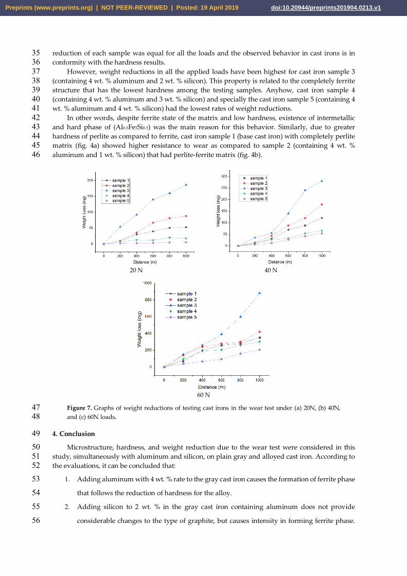
reduction of each sample was equal for all the loads and the observed behavior in cast irons is in 35 conformity with the hardness results. 36
However, weight reductions in all the applied loads have been highest for cast iron sample 3 37 (containing 4 wt. % aluminum and 2 wt. % silicon). This property is related to the completely ferrite 38 structure that has the lowest hardness among the testing samples. Anyhow, cast iron sample 4 39 (containing 4 wt. % aluminum and 3 wt. % silicon) and specially the cast iron sample 5 (containing 4 40 wt. % aluminum and 4 wt. % silicon) had the lowest rates of weight reductions. 41
In other words, despite ferrite state of the matrix and low hardness, existence of intermetallic 42 and hard phase of (Al0.5Fe3Si0.5) was the main reason for this behavior. Similarly, due to greater 43 hardness of perlite as compared to ferrite, cast iron sample 1 (base cast iron) with completely perlite 44 matrix (fig. 4a) showed higher resistance to wear as compared to sample 2 (containing 4 wt. % 45 aluminum and 1 wt. % silicon) that had perlite-ferrite matrix (fig. 4b). 46
20 N 40 N
60 N
Figure 7. Graphs of weight reductions of testing cast irons in the wear test under (a) 20N, (b) 40N, 47 and (c) 60N loads. 48
4. Conclusion 49 Microstructure, hardness, and weight reduction due to the wear test were considered in this 50
study, simultaneously with aluminum and silicon, on plain gray and alloyed cast iron. According to 51 the evaluations, it can be concluded that: 52
1. Adding aluminum with 4 wt. % rate to the gray cast iron causes the formation of ferrite phase 53
that follows the reduction of hardness for the alloy. 54
2. Adding silicon to 2 wt. % in the gray cast iron containing aluminum does not provide 55
considerable changes to the type of graphite, but causes intensity in forming ferrite phase. 56
Preprints (www.preprints.org) | NOT PEER-REVIEWED | Posted: 19 April 2019 doi:10.20944/preprints201904.0213.v1

Increasing the rate of silicon forms the intermetallic phase Al0.5Fe3Si0.5, which is followed by 57
greater hardness of the related cast iron. 58
3. The highest resistance and lowest resistance to wear were obtained in gray iron containing 4 59
wt. % aluminum with 4 wt. % and 2 wt. % silicon, respectively. 60
Acknowledgement: The authors cordially appreciate the supports made by Shahid Rajaei Teachers’ Training 61 University and Islamic Azad University/Khomeinishahr Branch and also University of Wisconsin-Milwaukee 62 for fulfilling this study. 63
References 64 [1] Y. E. Mangulkar and S. C. Borse, “Effect of addition of inoculants on mechanical properties & wear behaviour 65
of grey cast iron”, International Journal of Innovative Research in Science, Engineering and Technology, Vol. 5, 66 pp. 1131-1139, 2016. 67
[2] A. Sadeghi, A. Moloodi, M. Golestanipour, and M. Mahdavi Shahri, “An investigation of abrasive wear and 68 corrosion behavior of surface repair of gray cast iron by SMAW”, Journal of Materials Research and 69 Technology, 2016, In Press. 70
[3] J. Yamabea, M. Takagia, T. Matsuia, T. Kimurab, M. Sasaki, “Development of disc brake rotors for trucks with 71 high thermal fatigue strength”, JSAE Review, Vol. 23, pp. 105–112, 2002. 72
[4] A. Vadiraj and S. Tiwari, “Effect of silicon on mechanical and wear properties of aluminium-alloyed gray cast 73 iron”, Journal of Materials Engineering and Performance, Vol. 23, pp. 3001–3006, 2014. 74
[5] G. Cueva, A. Sinatora, W. L. Guesser, and A. P. Tschiptschin, “Wear resistance of cast irons used in brake 75 disc rotors”, Wear, Vol. 255, pp. 1256–1260, 2003. 76
[6] A. Asadi, M. Abbasi, M. Shameghli, “Non-destructive evaluation of Naihard 4 wear resistant cast-iron 77 microstructure, using vortex testing”, Metallurgy engineering, Vol. 59, pp. 43-44, 2015 78
[7] A. Kordijazi, Electrochemical Characteristics of an Optimized Ni-P-Zn Electroless Composite Coating, 79 Advanced Materials Research Vol. 1043 (2014) pp 124-128 80
doi:10.4028/www.scientific.net/AMR.1043.124 81 [8] S. M. Mostafavi Kashani and S. M. A. Boutorabi, “As-cast acicular ductile aluminum cast iron”, Journal of Iron 82
and Steel Research, International, Vol. 16, pp. 23-28, 2009. 83 [9] A. Malakizadi, I. Sadik, and L. Nyborg, “Wear mechanism of CBN inserts during machining of bimetal 84
aluminum-grey cast iron engine block”, Procedia CIRP, Vol. 8, pp. 88-193. 2013. 85 [10] N. Haghdadi, B. Bazaz, H. R. Erfanian-Naziftoosi, and A. R. Kiani-Rashid, “Microstructural and mechanical 86
characteristics of Al-alloyed ductile iron upon casting and annealing”, International Journal of Minerals, 87 Metallurgy and Materials, Vol. 19, pp. 812- 820, 2012. 88
[11] Saurabh Tiwari, Sourav Das and Venkat Ch, Mechanical properties of Al-Si-SiC composites, Accepted 89 Manuscript online 1 April 2019 2019 IOP Publishing Ltd, Material Research Express, 90 DOI:https://doi.org/10.1088/2053-1591/ab1521 91
[12] A. I. García-Diez, C. Camba-Fabal, Á. Varela-Lafuente, V. Blázquez-Martínez, J. Luís Mier-Buenhombre, 92 and B. Del Río-López, “Influence of silicon on wear behaviour of “Silal” cast irons”, DYNA, Vol. 81, pp. 93 216-221, 2014. 94
[13] I. Milosan, “The manufacturing of a special wear-resistant cast iron used in automotive industry, 2nd World 95 Conference On Business, Economics And Management- WCBEM 2013, Procedia - Social and Behavioral 96 Sciences, Vol. 109, pp. 610-613, 2014 97
[14] N. Marumoto, H. Kashimura, K. Yoshida, T. Toyoda, T. Okane, M. Yoshida, “Dynamic measurements of the 98 load on gray cast iron castings and contraction of castings during cooling in furan sand molds”, Journal of 99 Materials Processing Technology, Vol. 237, pp. 48-54, 2016. 100
[15] A. Shayesteh-Zeraati, H. Naser-Zoshki, A. R. Kiani-Rashid, and M. R. Yousef-Sani, “The effect of aluminium 101 content on morphology, size, volume fraction, and number of graphite nodules in ductile cast iron, in: 102 Proceedings of the Institution of Mechanical Engineers, Part L: Journal of Materials: Design and Applications, 103 Vol. 224, pp. 117-122, 2010 104
Preprints (www.preprints.org) | NOT PEER-REVIEWED | Posted: 19 April 2019 doi:10.20944/preprints201904.0213.v1

[16] M. S. Soiński, A. Jakubus, P. Kordas, and K. Skurka, “The effect of aluminium on graphitization of cast iron 105 treated with cerium mixture”, Archives of Foundry Engineering, Vol. 14, pp. 95-100, 2014. 106
[17] K. Ankamma, “Effect of trace elements (boron and lead) on the properties of gray cast iron”, Journal of the 107 Institution of Engineers (India): Series D, Vol. 95, pp. 19–26, 2014. 108
[18] A. Shayesteh-Zeraati, H. Naser-Zoshki, A. R. Kiani-Rashid, “Microstructural and mechanical properties 109 (hardness) investigations of Al-alloyed ductile cast iron”, Journal of Alloys and Compounds, Vol. 500, pp. 129-110 133, 2010. 111
[19] A. R. Kiani-Rashid and D. V. Edmonds, “Carbide precipitation in microstructure of austempered ductile 112 irons containing 0.48% and 4.88% Al”, International Journal of ISSI, Vol. 2, pp. 1-8, 2005. 113
[20] M. Sheikholeslami and S. M. A. Boutorabi, “A research on the calculation of graphitization ability of gray 114 cast iron”, Iranian Journal of Materials Science & Engineering, Vol. 9, pp. 28-33, 2012. 115
116
Preprints (www.preprints.org) | NOT PEER-REVIEWED | Posted: 19 April 2019 doi:10.20944/preprints201904.0213.v1