Embed Size (px)
Citation preview

article accelerator, a device that use electric and magnetic fields to raise the energy of
electrons, protons and ions to energies far above thermal levels. In the acceleration
process the particle velocities are increased (particles are accelerated), often to levels
extremely close to the speed of light. The most important types of accelerators are
electrostatic accelerators, cyclotron, synchrotrons, and linear accelerators. The
technologies that constitute modern accelerators are numerous and varied. They include
generators of radio-frequency power, fast electronics and feedback systems, complex
diagnostic instrumentation and controls, ultra-high vacuum components, powerful, high
precision magnets - both room temperature and cryogenic and sophisticated alignment
and support systems. Accelerators were once referred to as "atom smashers" because a
primary impetus for their development was as a tool for the investigation of the properties
of atomic nuclei and "elementary" particles. Although many small accelerators are made
as medical tools (such as for radiation therapy) and for industrial applications (such as ion
implantation in semi-conductors), the major use of large accelerators is as an instrument
for research.
The accelerator is sometimes called the "physicists microscope". Physicists use
many forms of ionizing radiation as the microprobes to study the structure of matter on an
ever smaller scale. To study nuclear and sub-nuclear processes, the probe radiation may
be protons, electrons or ions. Quantum mechanics tells us that a beam of particles has an
associated wavelength, just as a beam of light does. That wavelength decreases as the
energy of the beam increases. The smaller the wavelength of the radiation, the smaller the
objects that can be "seem" or probed but the larger and more complex the size of the
accelerator. The advance of microscopy has demanded ever higher energy probes. The
earliest sources of energetic radiation were naturally occurring radioactive materials.
Unfortunately the utility of radioactive materials is limited, because the investigator has
only a limited variety of particles, intensities and probe energies available. In the 1930's
scientists began to build a variety of machines to provide a more comprehensive variety
of beam sources. Accelerators now produce all the desired radiation probes at high
energy. If the desired probes are X-rays or gamma rays, the starting particles in the
accelerator are electrons that produce photons via the bremsstrahlung or synchrotron
radiation process. Neutrons are produced by bombarding a suitable target with a
concentrated beam of high energy protons or deuterons.
The energy of nuclear particles is measured in measured in units of electron-volts
(eV). This unit is based on the fundamental principle that a charged particle, when
subjected to an electric force, is accelerated in the direction of the force. If an electron is
travels from the negative electrode to positive electrode at a voltage difference V, it gains
an energy of V electron-volts. The energies available from accelerators range from
thousands of electron volts to that available at the world's largest machine, nearly one
trillion electron volts The generally used abbreviations are as follows:
1,000 eV = 103 eV = 1 keV
1,000,000 eV = 103 eV = 1 MeV
109 eV = 1 GeV
1012 eV = 1 TeV
To improve the signal–to–noise ratio in experiments and to uncover rare processes, the
advance of accelerator based microscopy also demands ever brighter sources of radiation.
These two characteristics, probe energy and probe brightness (or intensity), define the
technical frontiers that continue to challenge accelerator builders.
Basic Principles:
The basic scheme of a particle accelerator consists of three stages: 1) beam formation
and injection, 2) beam acceleration, and 3) beam extraction to a target or beam collisions
within the accelerator itself. Every accelerator begins with an injector consisting of a
directional source of low energy charged particles (electrons, protons or other ions) plus
the associated high voltage electrodes and magnets that extract and form the beam .The
first accelerators used hydrogen gas passing through a discharge or passing by a hot
filament as a source of protons. In this procedure the discharge strips the electron from
the atoms leaving a bare proton. Refinements of this technique (or analogous ones with
other gases) are still used to produce beams of protons (heavy ions). The source
generates the particle beam, which is characterized by an average initial energy, beam
current, cross-sectional area and mean angular divergence. The quality of the injected
beam is characterized by the product of the beam radius and divergence; this product is
called the beam emittance. Smaller emittance implies better quality of the final, high
energy beam of particles. In analogy with optics the particle current divided by the
emittance (which is equal to the particle density divided by the divergence) is called the
brightness. Many applications of modern accelerators require beams of the highest
possible brightness. The beam is produced in or injected into one or more acceleration
chambers where electrical forces increase the velocity (and therefore the energy) of the
particles.
In its simplest and earliest form, the accelerator increases the energy of the particles
by subjecting the beam to a static high voltage electric field within a highly evacuated
structure. The energy achievable using electrostatic fields to accelerate charged particles
is restricted by the ability of insulators (and the vacuum) in the accelerator to sustain high
electric fields without electrical breakdown. Electrostatic injectors of electrons and ions
(with mass up to uranium) to energies of 30 keV to 1 MeV are still used as the "front end"
of many modern accelerators.
Generating the high voltage is a technical challenge. The high voltage itself maybe be
generated by charging a series of capacitors in parallel and then applying the voltage
across a series of acceleration tubes in series. In this way Sir John Cockcroft and Ernest
Walton achieved voltages as high as 1 MV in 1931. An important practical disadvantage
of this approach is that the high voltage also appears on the outside of the structure
constituting a high voltage hazard to experimenters. The next year invented an
alternative approach. In the Van de Graff generator (see Figure 1) an insulated belt carries
electric charges from a source at ground potential up to a metal dome that accepts the
charges and thereby increases its potential above ground. Single stage Van de Graff
generators can provide voltages as high as 10 MV. Multi-stage machines have produced
protons with energies as high as 30 MeV.
If short burst of energy particles is needed rather than a continuous beam, one can
exploit the fact that insulators can withstand much higher fields for very short (<1µs)
periods. Pulsed diodes can achieve single stage voltages of up to 15 MV in very low
impedance structures. Consequently pulsed diodes can deliver several tens of kiloamperes
of beam current; in contrast with the tens of milliampere currents accelerated in
electrostatic accelerator. A common means of generating the high voltage is the Marx
generator. Similar to the Cockcroft-Walton, one charges a collection of capacitors in
parallel and discharges them in series across a single gap. The discharge form the Marx
launches a high voltage pulse along a transmission line or pulse forming network to shape
the temporal characteristics (such as the rise time) of the pulse. The beam electrodes
terminate the line and deliver the beam. Large, pulsed, electron diodes are used in for
flash radiography and for generating extremely large electromagnetic pulses to test
military components. Researchers at Sandia Laboratories in the US and at the
Khurchatov institute in Russia have built ion diodes generating hundreds of kiloamperes
of light ions for tens of nanoseconds to investigate inertial confinement fusion.
One may also exploit the principle of magnetic induction; that is, the principle of the
transformer. If one changes the flux through a torroid of ferromagnetic material by
driving a time-changing current through a conductor (primary winding) that loops around
the torroid, one will induce a voltage along the axis of the torroid. The beam passing
along the axis acts as the "secondary winding" of the transformer; and receives a voltage
boost as it traverses the core. The voltage in a single stage of an induction accelerator may
be as high as a few hundred kV for periods of a few hundred nanoseconds. By stacking
many such cores in series, Nicholas Christofilos was able to produce a beam of > 100 A
of 5 MeV electrons in 1962. Accelerators based on this induction principle are now
thought to be excellent means of delivering energy to a capsule of deuterium-tritium for
inertial confinement fusion.
If the accelerating voltage oscillates at radio frequencies (rf), the accelerator structure
can also sustain much higher electric fields without electric breakdown than in the case of
static voltages. Using rf-fields to accelerate particles presents a potential conceptual
difficulty: the sign of the field rapidly alternates between accelerating and decelerating.
Were the particle to traverse the gap between two plates with an rf-voltage applied the
direction of the force on a particle would also oscillate; the net effect might be no
acceleration at all. The two principal conceptual approaches to overcoming this difficulty
that were discovered in the late 1920's are the basis of most modern accelerators.
Linear Accelerators (linacs)
The critical feature that allows rf-fields to be used for long, multi-stage accelerators is
that the field varies in space as well as in time. At any given time the strength of the
varies sinusoidally over a distance characterized by the wavelength of the rf-field. At any
given point of space the field strength varies sinusoidally in time. If one notes the position
of the field maxima, one sees that these maxima appear to move through space at a
velocity which is called the phase velocity of the field. As time progresses the particles in
the accelerator change positions. Hence the particles could move in a way such that the
local field is always accelerating; that is, the particles continually leave the regions where
the accelerating field is decreasing (or even reversing) and enter regions where the field
is increasing. Alternatively they could move to a region in which they are shielded by a
metallic structure from the field while it is decelerating. The first use of rf-fields in a
linear structure was in 1929. Rolf Wideroë accelerated ions in a short, structure
composed of coupled, resonant, radio frequency cavities. When the cavities are designed
so that the phase velocity of the field matches the velocity of the particles, then as the
particles run down the accelerator, the beam will experience continual acceleration like a
surfer riding a wave. The velocities of protons or ions can change markedly during the
acceleration process. Consequently the phase velocity of the wave, vph, must likewise
increase in synchronism with the beam along the structure. As electrons can be injected
into the accelerator structure at nearly the speed of light, c, the structure typically has a
constant vph = c.
The alternative approach to avoiding the decelerating phase of the radio frequency
electric field is to shield the beam from the field during this period. This approach, first
exploited by Eanest O. Lawrence in the cyclotron, is the basis of the drift tube or Alvarez
linac. Such a linac consists of long evacuated tube which contains a long number of
hollow metal drift tubes as shown in Figure 2 (fig. 8 of the present text). Each of the tubes
is connected in succession to an rf-transmitter via a transmission line through which the
accelerating passes at near the speed of light. Thus each tube is successively charged to a
high voltage. If a charged particle leaves the injector at the right time it will be
accelerated toward the first tube acquiring a certain amount of energy. Once inside the
tube; the particle will drift at a constant velocity through the tube. If the tube is of the
appropriate length, the particle will emerge just as the accelerating voltage advances one
cycle. In that case the second tube will be at the right voltage to accelerate the ion toward
the second tube. Typical voltages are hundreds of thousands of volts. This process is
repeated with the particle acquiring an increment of energy in each step. As that velocity
of the ion increases, the tubes must be longer and longer to maintain synchronism with
the field. Eventually the ion velocity will be very close to the speed of light; at that point
the length of the tubes reaches their limiting, constant length.
The spatial variation of the field also introduces a limitation on the temporal structure
of the beam; for any bunch of finite length, the actual accelerating field will varies within
the bunch. Consequently, the length of the "bunch" of particles must be short with respect
to the rf-wavelength of the accelerating field due to the spatial variation of the electric
field. Otherwise the particles in the bunch will experience a significantly different degree
of acceleration. Excessive energy variation may increase the difficulty of focusing the
beam due to chromatic aberrations of the magnetic lenses, it may also decrease the utility
of the beam for the specific application desired. The energy variation can also lead to
focusing the bunch in the axial direction.
Consider the case of a non-relativistic bunch of ions moving at an initial velocity, vo.
The longitudinal electrical space charge forces act to accelerate the head of the beam and
decelerate the tail. By timing the bunch properly with respect to the rf-field as
illustrated in Fig. 3, the tail can be accelerated more strongly than the head. This proper
phasing of the beam and accelerating field can compensate the defocusing due to space
charge and energy spread. For some range of values of the central phase of the bunch,
there results a centering and oscillation of the particles about the phase stable point. This
phenomenon, known as phase stability, is important to linear ion accelerators, and it is
essential to modern circular accelerators of both electrons and ions.. The "price" of phase
stability is the limiting of the duty cycle of the accelerator to values well below unity.
During the acceleration process all real beams have a tendency to expand in radius
due to two effects: 1) the mutual electrostatic repulsion of the particles and 2) the finite
spread in transverse (thermal) velocities. The first tendency is reduced as the beam gets to
higher velocities because the magnetic field associated with the beam current tends to
pinch the beam together and for relativistic beams nearly cancels the transverse space
charge defocusing force. Hence, the first effect is of particle importance to ion
accelerators but is nearly negligible for electron accelerators in which the beam is injected
at relativistic velocities. The second effect, associated with the emittance of the beam is
important for all accelerators.
By surrounding the beam by magnetic fields with a direction perpendicular to the
beam axis and with a strength proportional to the distance outward from axis, one can
confines the particles near the axis by an harmonic potential. The self-magnetic field of a
beam with a uniform charge distribution has such a potential. Unfortunately it is canceled
by the space charge repulsion. Thus external fields are required to hold the beam together.
Quadrupole magnets also provide such fields. Although a quadrupole will focus the
particles in one plane transverse to the average motion, it will defocus the beam in the
other transverse plane. The "strong focusing" principle, discovered by Ernest Courant,
Stanley Livingston and Nicholas Christofilos, is based on the fact that the combination of
two quadrupoles separated by drift spaces and arranged with alternating focusing and
defocusing planes leads to net focusing in all planes perpendicular to the beam motion.
Drift tube linacs are still used in proton linacs for those portions which raise the
energy of the beam from a few MeV to about 100 MeV. Early electron linacs such as the
1 GeV linac built at Stanford University also used the drift tube approach with the length
of the tubes being constant once the beam was injected at an energy of 1 GeV. More
modern electron linacs of which the two mile long, 50 GeV machine at the Stanford
Linear Accelerator Center (SLAC) is the largest example use the principle of the
electrons "surfing" the electromagnetic field to accelerate the beam at almost 20 MeV
per meter of accelerating structure. At SLAC large tubes called klystrons supply the
radio-frequency power at a nearly 3 GHz. New developments of higher frequency tubes
and accelerating structures at roughly 11 GHz will make it possible for future electron
linacs to have average energy gains of 50 to 100 MeV per meter.
The highest energy proton linac is LAMPF at the Los Alamos National laboratory in
New Mexico. Using copper resonant cavities with an accelerating field of roughly 2 MeV
per meter, it accelerates - for brief periods, a beam of up to 1 milliampere of protons to
800 MeV . Originally built as a "meson factory to produce intense beams of pions and
muons, LAMPF will be upgraded to produce a beam of over 100 kW of long-term
average power. The beam will then impact a heavy metal target to produce copious
neutrons via the nuclear spallation process. This neutron source will be used for
fundamental research in the material sciences and biological sciences. New proton linacs
operating at average powers up to 50 MW are being designed for applications such as the
breeding of tritium and the transmutation of radioactive waste.
Superconducting rf structures have also been developed for the acceleration of heavy-
ions as well as protons. The largest superconducting proton linac serves as an injector for
the HERA colliding beam accelerator at the German laboratory DESY in Hamburg.
Recent advances in the technology of fabrication and preparation of superconducting rf-
cavities suggest that accelerating fields of 15 -25 MeV per meter can be achieved at
frequencies of 500 MHz. Such low frequency structure are very attractive for the
generation of intense beams as the problems of controlling beam losses to ultra-low levels
are vastly simplified due to the large apertures of the structure
Circular accelerators
An elegant and economical approach to accelerating a beam by many small kicks is
to have the beam pass across the same accelerating gap many times. To do this the
particles must be deflected by strong magnetic fields into a roughly circular orbit. This
approach was first taken by Ernest O. Lawrence and Stanley Livingston with their
invention of the proton cyclotron in 1930. As in the drift tube linac the beam is removed
from the region containing the electric fields when the fields are of the wrong phase. If a
charged particle of mass m and charge q moves with velocity v in a magnetic field of
strength H directed perpendicular to the instantaneous direction of motion, it will move
in a circle of radius R = mv/qH. In the accelerator as v increases, R increases. Thus the
protons (or heavier ions) spiral outward to larger radii. If the two high voltage cavities
are shaped like the letter D, then on each turn the beam will cross a gap with time
varying electric fields (Fig. 4 -fig 2 of the original text). Lawrence's insight was to note
that intervals between crossings is constant (for non-relativistic particles) since the
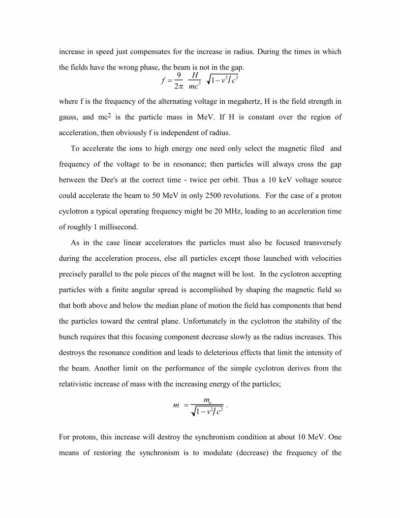
increase in speed just compensates for the increase in radius. During the times in which
the fields have the wrong phase, the beam is not in the gap.
f 9
2 H
mc2 1 v
2c
2
where f is the frequency of the alternating voltage in megahertz, H is the field strength in
gauss, and mc2 is the particle mass in MeV. If H is constant over the region of
acceleration, then obviously f is independent of radius.
To accelerate the ions to high energy one need only select the magnetic filed and
frequency of the voltage to be in resonance; then particles will always cross the gap
between the Dee's at the correct time - twice per orbit. Thus a 10 keV voltage source
could accelerate the beam to 50 MeV in only 2500 revolutions. For the case of a proton
cyclotron a typical operating frequency might be 20 MHz, leading to an acceleration time
of roughly 1 millisecond.
As in the case linear accelerators the particles must also be focused transversely
during the acceleration process, else all particles except those launched with velocities
precisely parallel to the pole pieces of the magnet will be lost. In the cyclotron accepting
particles with a finite angular spread is accomplished by shaping the magnetic field so
that both above and below the median plane of motion the field has components that bend
the particles toward the central plane. Unfortunately in the cyclotron the stability of the
bunch requires that this focusing component decrease slowly as the radius increases. This
destroys the resonance condition and leads to deleterious effects that limit the intensity of
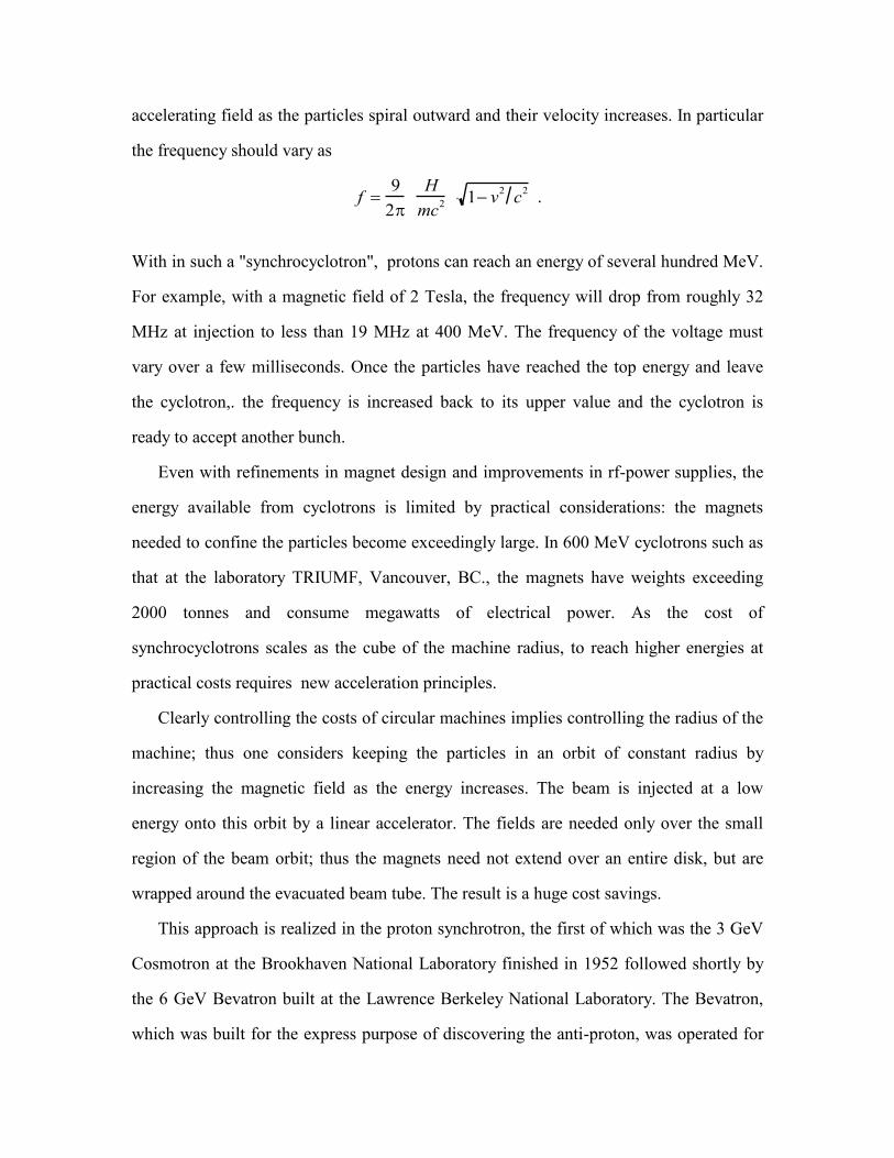
the beam. Another limit on the performance of the simple cyclotron derives from the
relativistic increase of mass with the increasing energy of the particles;
m mo
1 v2 c2.
For protons, this increase will destroy the synchronism condition at about 10 MeV. One
means of restoring the synchronism is to modulate (decrease) the frequency of the
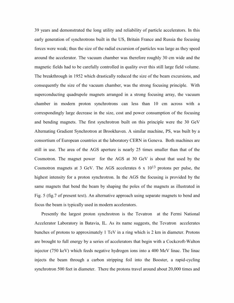
accelerating field as the particles spiral outward and their velocity increases. In particular
the frequency should vary as
f 9
2 H
mc2 1 v
2c
2 .
With in such a "synchrocyclotron", protons can reach an energy of several hundred MeV.
For example, with a magnetic field of 2 Tesla, the frequency will drop from roughly 32
MHz at injection to less than 19 MHz at 400 MeV. The frequency of the voltage must
vary over a few milliseconds. Once the particles have reached the top energy and leave
the cyclotron,. the frequency is increased back to its upper value and the cyclotron is
ready to accept another bunch.
Even with refinements in magnet design and improvements in rf-power supplies, the
energy available from cyclotrons is limited by practical considerations: the magnets
needed to confine the particles become exceedingly large. In 600 MeV cyclotrons such as
that at the laboratory TRIUMF, Vancouver, BC., the magnets have weights exceeding
2000 tonnes and consume megawatts of electrical power. As the cost of
synchrocyclotrons scales as the cube of the machine radius, to reach higher energies at
practical costs requires new acceleration principles.
Clearly controlling the costs of circular machines implies controlling the radius of the
machine; thus one considers keeping the particles in an orbit of constant radius by
increasing the magnetic field as the energy increases. The beam is injected at a low
energy onto this orbit by a linear accelerator. The fields are needed only over the small
region of the beam orbit; thus the magnets need not extend over an entire disk, but are
wrapped around the evacuated beam tube. The result is a huge cost savings.
This approach is realized in the proton synchrotron, the first of which was the 3 GeV
Cosmotron at the Brookhaven National Laboratory finished in 1952 followed shortly by
the 6 GeV Bevatron built at the Lawrence Berkeley National Laboratory. The Bevatron,
which was built for the express purpose of discovering the anti-proton, was operated for
39 years and demonstrated the long utility and reliability of particle accelerators. In this
early generation of synchrotrons built in the US, Britain France and Russia the focusing
forces were weak; thus the size of the radial excursion of particles was large as they speed
around the accelerator. The vacuum chamber was therefore roughly 30 cm wide and the
magnetic fields had to be carefully controlled in quality over this still large field volume.
The breakthrough in 1952 which drastically reduced the size of the beam excursions, and
consequently the size of the vacuum chamber, was the strong focusing principle. With
superconducting quadrupole magnets arranged in a strong focusing array, the vacuum
chamber in modern proton synchrotrons can less than 10 cm across with a
correspondingly large decrease in the size, cost and power consumption of the focusing
and bending magnets. The first synchrotron built on this principle were the 30 GeV
Alternating Gradient Synchrotron at Brookhaven. A similar machine, PS, was built by a
consortium of European countries at the laboratory CERN in Geneva. Both machines are
still in use. The area of the AGS aperture is nearly 25 times smaller than that of the
Cosmotron. The magnet power for the AGS at 30 GeV is about that used by the
Cosmotron magnets at 3 GeV. The AGS accelerates 6 x 10¹³ protons per pulse, the
highest intensity for a proton synchrotron. In the AGS the focusing is provided by the
same magnets that bend the beam by shaping the poles of the magnets as illustrated in
Fig. 5 (fig.7 of present text). An alternative approach using separate magnets to bend and
focus the beam is typically used in modern accelerators.
Presently the largest proton synchrotron is the Tevatron at the Fermi National
Accelerator Laboratory in Batavia, IL. As its name suggests, the Tevatron accelerates
bunches of protons to approximately 1 TeV in a ring which is 2 km in diameter. Protons
are brought to full energy by a series of accelerators that begin with a Cockcroft-Walton
injector (750 keV) which feeds negative hydrogen ions into a 400 MeV linac. The linac
injects the beam through a carbon stripping foil into the Booster, a rapid-cycling
synchrotron 500 feet in diameter. There the protons travel around about 20,000 times and
reach an energy of 8 GeV. Typically the Booster cycles twelve times in rapid succession
to load twelve bunches of protons, into the 6.3 km circumference Main Ring, yet another
proton synchrotron. Consisting of 1,000 conventional, copper-coiled magnets to bend and
focus the protons, the Main Ring accelerates protons to 150 GeV. Directly beneath the
Main Ring is the final synchrotron, the Tevatron which contains 1000 superconducting
magnets. The beam can also be extracted into multiple external beamlines 1 to 2 miles
long for experiments in external experimental areas.
Some of the experiments at Fermilab are performed by colliding the 1 TeV proton
beam with a counter-rotating beam of anti-protons also at 1 TeV. For these experiments
the anti-protons must be made with a high energy proton beam from the Main Ring that
bombard a metal target. The anti-protons produced in the collisions are collected and
accumulated in a separate accumulator ring at 8 GeV. When there are sufficient anti -
protons they are injected into the Main Ring, accelerated to 150 GeV and injected into the
Tevatron. There both the protons and anti-protons are accelerated simultaneously to full
energy and then allowed to collide.
Higher energy beams require stronger bending and the focusing fields to confine the
beam. Proton synchrotrons at multi-TeV energies (for sub-nuclear "microscopy”) require
thousands of superconducting bending and focusing magnets 5 to 15 meters in length
with several centimeter apertures and exquisite field precision and temporal stability.
Such a machine is presently in the design phase at CERN.
The major llimit to extending the enrgy frontier with proton synchrotrons is the cost
and complexity associated with their very large size. Even with the use of powerful
superconducting magnets the ill-fated Superconducting SupercColider with 40 TeV
beams would have been over 80 km in circumfirence. The coils of present
superconducting accelerator magnets are made of a ductile superconductor, niobium-
titanium. For economicalmagnet design the conductor should carry ≈ 2000 Amperes per
square millimeter . Operating at 4.2 K, even short samples of NbTi will not support
fields above 12 T (the critical field value, Hc); this means the current density falls to zero
at higher fileds.Thus practical Nb-Ti magnets the fields are limited to < 10 T. If the
limits on size of accelerators demands magnets with fields above 12 Tesla, a new
technology must be brought to bear. No known ductile materials have Hc above
approximately 12 Tesla; therefore, very high field dipole magnets will have to based on
brittle superconductors, such as Nb3Sn or Nb3Al with Hc above 20 T. A promising
alternative are the brittle, mixed oxides that are high temperature superconductors;
operating at <20 K these materials may provide current densities of 2000 Amperes per
square millimeter even above 15 Telsa. The magnetic pressures associated with such high
fields are hundreds of atmospheres. Not surprisingly the challenges of the mechamical
design are great.
Colliding beam accelerators
Not all of the energy of an accelerated particle is available to produce reactions. A
significant fraction is lost when the target particle recoils to satisfy the law of the
conservation of momentum. The useful available energy in such "fixed target"
experiments with projectiles of energy E and target particle of mass M is
Eavail 2EMc2
.
Thus fixed target experiments at the Tevatron have an available energy of limited to only
43 GeV. In contrast in the Tevatron collider mode in which the counter rotating protons
and anti-protons can run headlong into each other, the total momentum of the colliding
particles is zero and all the energy (2E) is available. In the Tevatron this energy is nearly
2 TeV. This great gain in energy reach comes at the expense of a greatly reduced collision
rate between particles as the two tenuous beam pass through each other. This reaction rate
is measured by the 'luminosity' defined as the number of collisions per second for a
reaction having a given cross section. The luminosity scales linearly with beam energy,
with beam current, and inversely with the beam radius; the energy of the beam in the
collider is set by the energy scale of the physics to be investigated. In order for
maximize the luminosity, the beams must be made as dense as possible at the collision
point. Consequently the technical challenge in designing colliders is focusing the beams
at the collision point to an exceedingly small spot and increasing the beam current as
much as practical; for sufficient luminosity the circulating current may exceed 1 Ampere.
Another sophisticated technical challenge is to provide extremely high vacuum in the
collider. As the collisions between beam particles is relatively rare, the collisions with
residual gas molecules is an important competing process that can deplete the beam faster
that the desired the beam-beam collisions themselves. Beam-gas collisions are also a
source of unwanted background in the detector that can obfuscate the physics to be
studied. Typically the vacuum in colliders must be in the range of 10-11 to 10-9 Tore (mm
of mercury) depending on the collider luminosity.
The desire to explore the energy frontier of high energy physics has lead to the
construction of proton colliders at CERN and Fermilab and of many colliding beam
electron devices throughout the world. An accelerator (HERA) that collides electrons and
protons has been built at the German laboratory DESY in Hamburg. The first proton
collider was the Intersecting Storage Rings (ISR) at CERN. There 26 GeV protons and
anti-protons were collided in a 1.6 km circumference ring. Beam currents as high as 50
Amps were stored for several days. The highest energy collider is presently the Tevatron
with nearly 1 TeV per beam. An even larger (28 km circumference) collider, the Large
Hadron Collider (LHC) is presently in design at CERN. The LHC will collide 7 TeV
proton beams with an unprecedented luminosity. It will be built in the tunnel that
presently houses LEP, the highest energy electron-position collider. There the beams have
been colliding at 50 GeV per beam; an upgrade in progress will raise the energy to 100
GeV per beam.
At lower energies in one can accelerate more intense electron beams making it
possible to explore rare process associated with the decay of B and K mesons via the
electroweak force. A number of such machines sometimes known as "flavor factories" are
now being built in the US, Japan, and Italy. Typically these machines are built with two
storage rings - one containing electrons, the other, positrons - intersecting in one or two
interaction regions. Each ring contains numerous bunches of particles yielding total beam
currents exceeding 1 Ampere. The beam energies are chosen so that the available energy
corresponds to a resonance that decays into the short lived particles (B mesons or K
mesons) to be studied. The basis the design of these machines is the electron synchrotron
and the storage ring. The energy limit of circular electron-positiron colliders is the
emission of copious radiation by the beam (synchrotron radiation, discussed below).
This limtation can be overcome with linear colliders in which the emission of
synchrotron radiation is vastly reduced during the acceleration process. As its name
suggests, the linear collider consists of two high energy linear accelerators that direct high
intensity beams, one of electrons the other of positrons, at each other. The beams pass
through each other a single time beforeand travel on to a beam dump. The first linear
colliding beam facility is the Stanford Linear Collider, SLC, which uses the 2 mile long
SLAC linac operating at 50 GeV. In the SLC bunches of electrons and positrons are
accelerated in the same linac and a separted when the beams reach full energy. The
elctron and positron bunches are then transported around separate arcs, in a configuration
resemling a stethescope, and focused to a size of 2 µm at the collision point. The next
step in linear collider development is expected to be at TeV energies. Such colliders will
be limited by cost considerations to 20 or 30 kilometers in length and will require
economical means of increasing the accelerating fields, by up to ten times beyond those
commonly found in existing accelerators. The search for economical means of
acceleration has lead to the design of new accelerator structures and high power sources
of radio frequency power operating in the range of 10 to 35 GHz. As the cross sections
for processes decrease with the invere square of the beam energy, the luminosity of
electron positron colliders must be made extremely large. Consequently the beam
densities must be very high. In TeV linear colliders, the beams may have a size of 10 nm,
far smaller than the 2 µm size in the SLC. Such small beam sizes imply powerful, very
stable magnets controlled by sophisticated feedback electronics to keep the focusing
elements in precise alignment. When the electron and positron beams pass through one
another the electrical forces within the beams cancel, but the magnetis forces reinforce
each other. The resulting fields can be of the order of 104 Tesla. These huge fields can
severely disrupt the beams and induce large energy spreads due the emission of
synchrotron radiation. This effect plus the economics of building ever longer machines
will limit the ultimate energy reach of electron-positron colliders:
Electron storage rings
Electron synchrotrons are based upon the same operating principle as proton
synchrotrons. They have an important simplifying feature. The small mass of the electron
allows the beam to be injected at very nearly the velocity of light. As adding energy
cannot change the speed much, the electron synchrotron can operate with a fixed
frequency operating voltage as long as the beam is injected at an energy of roughly 10
MeV. This simplification is more than offset by another consequence of the small
electron mass. As electron is bend around in a circle, the centripetal acceleration causes
the electron to emit photons (radiation) through a process called synchrotron radiation.
The power, P, emitted varies as the fourth power of the beam energy, E, linearly with the
beam current, I, and inversely with the radius of the machine, R; that is P is proportional
to (E/m)4IR-1. Thus the energy lost in each revolution of the beam around the accelerator
must be replaced by the rf-accelerating fields supplied by the accelerating cavities. In high
intensity "flavor factories" this emitted power can be tens of megawatts.
Circular accelerators like electron synchrotrons can serve not only to increase the
energy of particle beams but also to store large circulating currents of particles at a
constant high energy. Storage rings have two major applications: 1) colliding beams for
nuclear and elementary particle research. as discussed above and 2) "light sources" for use
in atomic physics, material science, chemistry, biological science and medicine.
The average energy of the photons emitted as synchrotron radiation is proportional to
(E/m)3R-1. Consequently GeV electrons in a storage ring emit copious synchrotron
radiation with energies in the ultra-violet and x-ray range. Most of the photons are
emitted within a narrow angle in the vertical (non-bend) plane of m/E. As the electron
beam in modern, GeV storage rings can have a radius of tens of microns, the x-ray beam
emitted can be extremely bright, bright enough to serve as a powerful probe the structure
of materials. The radiation is emitted tangential to the curving trajectory of the electrons.
Hence every bending magnet in an electron storage ring provides a sweeping
"seaerchlight of radiation as the bunch of electrons passes through the magnet. Radiation
escapes down long, evacuated, radiation beamlines tangential to the main vacuum
chamber. Aong these beamlines slits and collimators define a narrow bea, and
monochrometers provide for the selection of x-ray energy to within a narrow bandwidth.
Storage rings with the primary purpose of providing synchrotron radiation to users are
known by the generic named "light sources". The first generation of light source used
storgare rings that were originally built for high energy physics. A notable example of
such a source is the 3 GeV SPEAR ring at the Stanford Synhrotron Radiaon Laboratory
(SSRL), which was one of th sites for the discovery of "charmed mesons". The first
generation sources typically have not had the flexibility to accomodate the hundreds of
simultaneous users that a dedicated light source can service. Consequently, as the demand
for high flux, high intensity grew, a second generation of light sources was built with the
needs of radiation users incorporated from the outset. In particular arrays of magnets were
chosen with the express intention os minimizingthe emittance of the electron bean. Low
emittance implies smaller beam sizes and thus brighter sources of radiation. The X-ray
and vuv rings at the Brookhaven labortory are typical of this generation.
The brightness of the emitted radiation can be increased still more if the beam is
wiggled back iand forth in a sinusoidal pattern such that the radiation from each bend is
superimposed. Undulators, magnet structures to provide such a motion, are of a series
small angle dipole bends placed along a striaght beam line. The brightness of undulator
radition can be hundreds of times larger than that from bend magnets. Construction of a
third generation of light sources designed to incorporate many such undulators began in
the mid-1980's. Notable first examples of third generation sources are the 1.5 GeV
Advanced Light Source (ALS) in Berkeley, producing soft x-rays, and the 6 GeV
Advanced Photon Source (APS) at the Argonne National Laboratry and the European
facility ESRF, in Grenoble, France. APS and ESRF are sources of hard x-rays. Several
other light sources have been and are being built throughout the world based on the
success of these machines. In innovative design technique for a machine to provide high
brightness from the infrared all the way to hard x-rays is have the array of bending
magnets be a combination of warm dipoles at ≈ 1.5 Tesla and much shorter
superconducting dipoles at �several Telsa. This approach is being explored for a new
light source in Switzerland and as a retrofit for the ALS.
The breadth of scientific uses for synchrotron radiation is is already large and still
growing. Extremely bright x-ray beams allow for a new generation of x-ray microscopes
to study biological systems in their normal aqueous envirmonment. They allows the rapid
analysis of the structure of viruses and proteins for the design of new pharmaceuticals
with precisely targeted efficacy against their disease-causing targets, and with less effect
on other structures in the body. Adverse side-effects of the drugs will be minimized. X-
ray beams now provide powerful microprobes for the identification of minute levels of
impurities and contaminants. These microprobes can provide a rapid way to "fingerprint"
environmental samples to identify routes of pollution and contamination. They can be
used to certify the cleaniness of large silicon wafers prior to expensive processing of very
highly integrated circuit and they offer the promise of new lithographic techniques to
provide feature sizes in integrated circuits smaller than 100 nm.
Accelerators in medicine
The use of accelerators is not confined serving as research tools or as sourcesof
process radiation in industry. Accelerators have found an essential, practical role in
therapeutic and diagnostic medicine. Many hospitals throughout the world have small
electron linacs that produce energetic x-rays for the irradiation of tumors. A much small
number use cyclotrons or synchrotrons to generate proton beams to irradiate a wide
variety of solid tumors. As the protons have the advantage of depositing their energy
more locally than x-rays, proton therapy is especially efficaceous in the treatment of brain
and eye tumors where the damage to the surrounding healthy tissue must be kept as small
as possible.
The availabilty of small proton accelerators has enabled an exciting diagnostic
technique, positron emission tomography (PET). PET is based on the absoption in
tissues to be imaged of radio-isotopes that emit a low energy positron when they decay.
When the positron anihilates with an electron in the tissue it produces a pair of 511 keV
gamma rays; these gamma rays are recorded by two detectors. Possibly the most
importtant PET isotope is O17, which is readily incorporated into fructose. As the
absortion of fructose is regulated by metabolism, the PET can be used to image
functionality rather than merely density variations in the tissue. Thus, imaging of the
metabolism of fructose in the brain can provide valuable insight into the loss of brain
functionality associated with diseases like Alzheimer's. The half-life of O17 is only two
minutes; other important PET isotopes also have short half-lives. Hence the spread of this
technique beyond laboratory research centers with reactors had to await the commercial

availability of small, easy to operate accelerators suitable for isotope production in
hospitals.