Embed Size (px)
Citation preview
Mike Holt Enterprises • www.MikeHolt.com • 888.NEC.CODE (632.2633) 55
ARTICLE
250 GROUNDING AND BONDING
Introduction to Article 250—Grounding and BondingNo other article can match Article 250 for misapplication, violation, and misinterpretation. Terminology used in this article has been a source for much confusion, but that’s improved during the last few NEC revisions. It’s very important to understand the difference between grounding and bonding in order to correctly apply the provisions of Article 250. Pay careful attention to the definitions that apply to grounding and bonding both here and in Article 100 as you begin the study of this important article. Article 250 covers the grounding requirements for providing a path to the earth to reduce overvoltage from lightning, and the bonding requirements for a low-impedance fault current path back to the source of the electrical supply to facilitate the oper-ation of overcurrent protection devices in the event of a ground fault.
Over the past several Code cycles, this article was extensively revised to organize it better and make it easier to understand and implement. It’s arranged in a logical manner, so it’s a good idea to just read through Article 250 to get a big picture view—after you review the definitions. Next, study the article closely so you understand the details. The illustrations will help you under-stand the key points.
Part I. General
250.1 Scope
Article 250 contains the following grounding and bonding requirements:
(1) What systems and equipment are required to be grounded.
(3) Location of grounding connections.
(4) Types of electrodes and sizes of grounding and bonding conductors.
(5) Methods of grounding and bonding.
250.2 Definition
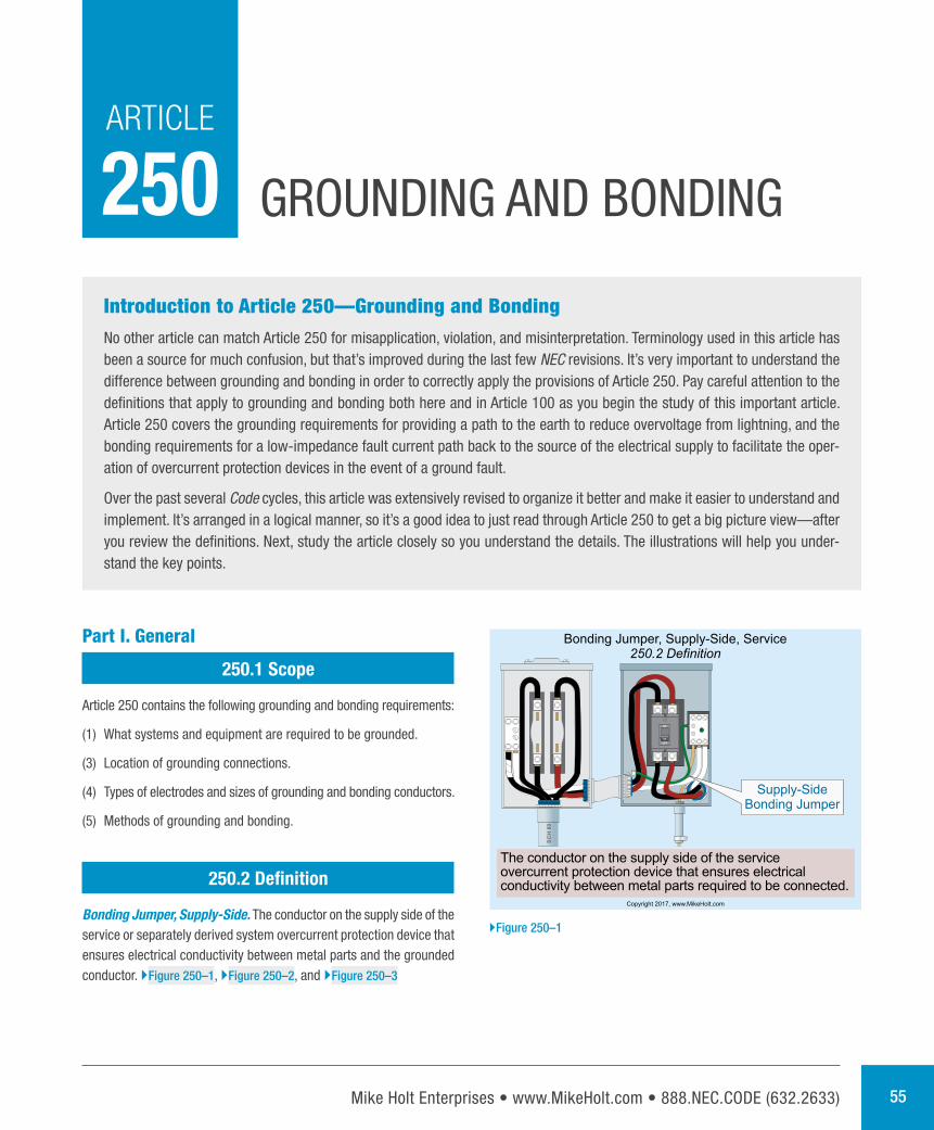
Bonding Jumper, Supply-Side. The conductor on the supply side of the service or separately derived system overcurrent protection device that ensures electrical conductivity between metal parts and the grounded conductor. }Figure 250–1, }Figure 250–2, and }Figure 250–3
SC
H80
Bonding Jumper, Supply-Side, Service250.2 Definition
Supply-SideBonding Jumper
Copyright 2017, www.MikeHolt.com
The conductor on the supply side of the serviceovercurrent protection device that ensures electricalconductivity between metal parts required to be connected.
}Figure 250–1
Mike Holt’s Illustrated Guide to Understanding 2017 NEC Requirements for Bonding and Grounding 56
250.4 | Grounding and Bonding
Author’s Comment:
nSystem grounding helps reduce fires in buildings as well as voltage stress on electrical insulation, thereby ensuring longer insulation life for motors, transformers, and other system components. }Figure 250–5
Note 1: To limit imposed voltage, the grounding electrode conductors shouldn’t be
any longer than necessary and unnecessary bends and loops should be avoided.
}Figure 250–6
250.4 Performance Requirements for Grounding and Bonding
(A) Solidly Grounded Systems.
Scan this QR code for a video of Mike explaining this topic; it’s a sample from the DVDs that accompany this textbook.
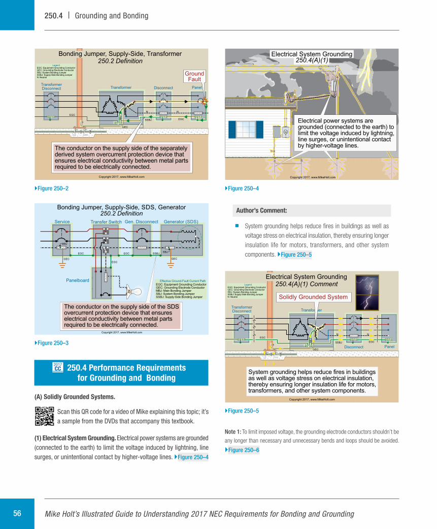
(1) Electrical System Grounding. Electrical power systems are grounded (connected to the earth) to limit the voltage induced by lightning, line surges, or unintentional contact by higher-voltage lines. }Figure 250–4
2017CC
TransformerTransformerDisconnect
Copyright 2017, www.MikeHolt.com
SSBJ
GEC
SB
JEGC
EGC
NN
Disconnect Panel
GroundFault
EGC: Equipment Grounding Conductor: Grounding Electrode ConductorGEC
: System Bonding JumperSBJ: Supply-Side Bonding JumperSSBJ
N: Neutral
Legend
The conductor on the supply side of the separatelyderived system overcurrent protection device thatensures electrical conductivity between metal partsrequired to be electrically connected.
Bonding Jumper, Supply-Side, Transformer250.2 Definition
}Figure 250–2
Electrical System Grounding250.4(A)(1)
Electrical power systems aregrounded (connected to the earth) tolimit the voltage induced by lightning,line surges, or unintentional contactby higher-voltage lines.
Copyright 2017, www.MikeHolt.com
}Figure 250–4
Transformer
Disconnect
TransformerDisconnect
Panel
Copyright 2017, www.MikeHolt.com
SSBJ
GEC
SB
JEGC
EGC
NN
Electrical System Grounding250.4(A)(1) Comment
Solidly Grounded System
System grounding helps reduce fires in buildingsas well as voltage stress on electrical insulation,thereby ensuring longer insulation life for motors,transformers, and other system components.
EGC: Equipment Grounding Conductor: Grounding Electrode ConductorGEC
: System Bonding JumperSBJ: Supply-Side Bonding JumperSSBJ
N: Neutral
Legend
}Figure 250–5
GEC
SBJSBJEGC EGC
EG
C
N
N
NN
Service
Panelboard
Generator ( )SDSGen. DisconnectTransfer Switch
Copyright 2017, www.MikeHolt.com
MBJ
Bonding Jumper, Supply-Side, SDS, Generator250.2 Definition
The conductor on the supply side of the SDSovercurrent protection device that ensureselectrical conductivity between metal partsrequired to be electrically connected.
GECGEC
SSBJSBJ
EGC
EGC
EGC
EGC: Equipment Grounding Conductor: Grounding Electrode ConductorGEC
MBJ: Main Bonding Jumper: System Bonding JumperSBJ
: Supply-Side Bonding JumperSSBJ
Effective Ground-Fault Current Path
}Figure 250–3
Mike Holt Enterprises • www.MikeHolt.com • 888.NEC.CODE (632.2633) 57
Grounding and Bonding | 250.4
Author’s Comment:
nGrounding metal parts helps drain off static electricity charges before flashover potential is reached. Static grounding is often used in areas where the discharge (arcing) of the voltage buildup (static) can cause dangerous or undesirable condi-tions [500.4 Note 3].
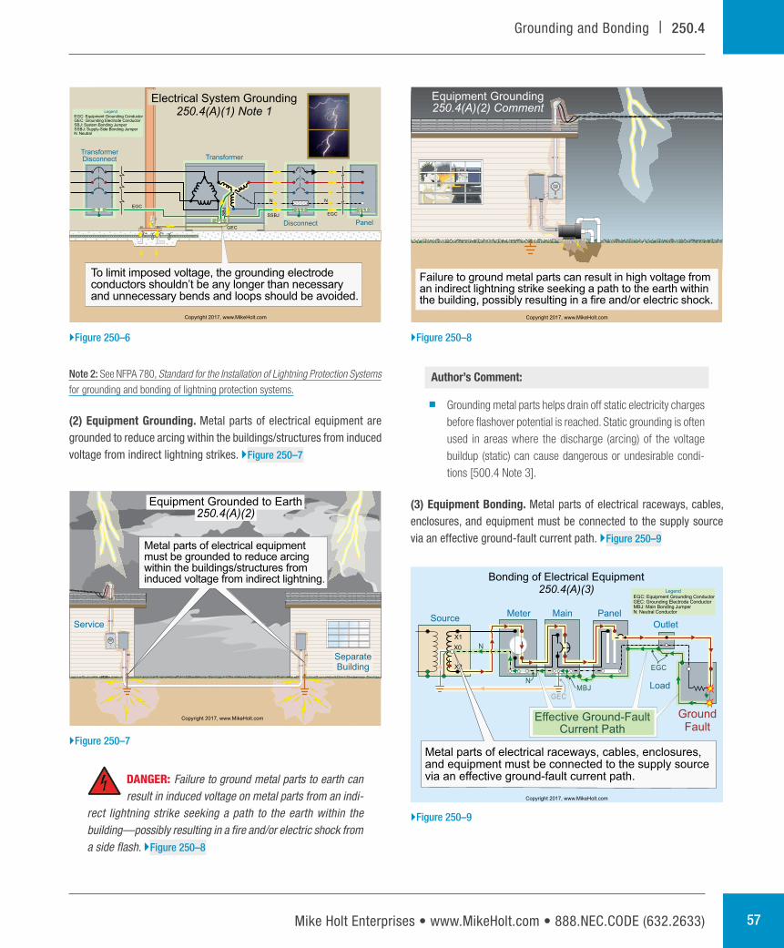
(3) Equipment Bonding. Metal parts of electrical raceways, cables, enclosures, and equipment must be connected to the supply source via an effective ground-fault current path. }Figure 250–9
Note 2: See NFPA 780, Standard for the Installation of Lightning Protection Systems
for grounding and bonding of lightning protection systems.
(2) Equipment Grounding. Metal parts of electrical equipment are grounded to reduce arcing within the buildings/structures from induced voltage from indirect lightning strikes. }Figure 250–7
DANGER: Failure to ground metal parts to earth can result in induced voltage on metal parts from an indi-
rect lightning strike seeking a path to the earth within the building—possibly resulting in a fire and/or electric shock from a side flash. }Figure 250–8
Transformer
Disconnect
TransformerDisconnect
Panel
Copyright 2017, www.MikeHolt.com
SSBJ
GECS
BJEGC
EGC
NN
Electrical System Grounding250.4(A)(1) Note 1
To limit imposed voltage, the grounding electrodeconductors shouldn’t be any longer than necessaryand unnecessary bends and loops should be avoided.
EGC: Equipment Grounding Conductor: Grounding Electrode ConductorGEC
: System Bonding JumperSBJ: Supply-Side Bonding JumperSSBJ
N: Neutral
Legend
}Figure 250–6
SeparateBuilding
Service
Equipment Grounded to Earth250.4(A)(2)
Copyright 2017, www.MikeHolt.com
Metal parts of electrical equipmentmust be grounded to reduce arcingwithin the buildings/structures frominduced voltage from indirect lightning.
}Figure 250–7
Equipment Grounding250.4(A)(2) Comment
Copyright 2017, www.MikeHolt.com
Failure to ground metal parts can result in high voltage froman indirect lightning strike seeking a path to the earth withinthe building, possibly resulting in a fire and/or electric shock.
}Figure 250–8
Meter
X1
X2
X0
Main
Outlet
Load
PanelSource
GroundFault
MBJN
N
EGC
Copyright 2017, www.MikeHolt.com
Effective Ground-FaultCurrent Path
EGC: Equipment Grounding ConductorGEC: Grounding Electrode Conductor
: Main Bonding JumperMBJN: Neutral Conductor
Legend
GEC
Bonding of Electrical Equipment250.4(A)(3)
Metal parts of electrical raceways, cables, enclosures,and equipment must be connected to the supply sourcevia an effective ground-fault current path.
}Figure 250–9

Mike Holt’s Illustrated Guide to Understanding 2017 NEC Requirements for Bonding and Grounding 58
250.4 | Grounding and Bonding
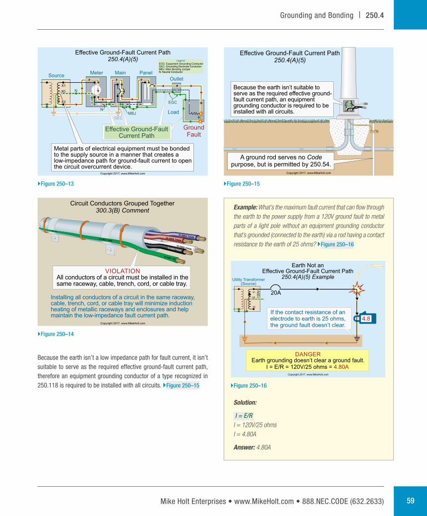
(5) Effective Ground-Fault Current Path. Metal parts of electrical race-ways, cables, enclosures, or equipment must be bonded together and to the supply source in a manner that creates a low-impedance path for ground-fault current that facilitates the operation of the circuit over-current protection device. }Figure 250–13
Author’s Comment:
nTo ensure a low-impedance ground-fault current path, all circuit conductors must be grouped together in the same raceway, cable, or trench [300.3(B), 300.5(I), and 300.20(A)]. }Figure 250–14
Author’s Comment:
nTo quickly remove dangerous voltage on metal parts from a ground fault, the effective ground-fault current path must have sufficiently low impedance to the source so fault current will quickly rise to a level that will open the branch- circuit overcurrent protection device. }Figure 250–10
nThe time it takes for an overcurrent protection device to open is dependent on the magnitude of the fault current. A higher fault current value will result in a shorter clearing time for the overcurrent protection device. For example, a 20A overcurrent protection device with an overload of 40A (two times the 20A rating) takes 25 to 150 seconds to open. The same device at 100A (five times the 20A rating) trips in 5 to 20 seconds. }Figure 250–11
(4) Bonding Conductive Materials. Electrically conductive materials likely to become energized, such as metal water piping systems, metal sprinkler piping, metal gas piping, and other metal-piping systems, as well as exposed structural steel members, must be connected to the supply source via an effective ground-fault current path. }Figure 250–12
Author’s Comment:
nThe phrase “likely to become energized” is subject to inter-pretation by the authority having jurisdiction.
The 100A overcurrent device quickly opens andremoves dangerous voltage from metal parts.
583Amps
120V
200 ft 8 AWG0.156 ohms
Fault Current =E
=120V
= 583AZ 0.206 ohms
200 ft 3 AWG0.05 ohms
100ADevice
Opening an Overcurrent Device
EGCSSBJSBJ
Copyright 2017, www.MikeHolt.com
EGC: Equipment Grounding Conductor: System Bonding JumperSBJ
: Supply-Side Bonding JumperSSBJ
Legend
}Figure 250–10
100A FaultClears in5 to 20
Seconds
40A FaultClears in25 to 150Seconds
40A
5 Sec
10 Sec
15 Sec
20 Sec
25 Sec
30 Sec
35 Sec
40 Sec
45 Sec
145 Sec
150 Sec
155 Sec
100A
Time-Current Curve20A Inverse Time Breaker
The higher the current, the faster the fault clears.
MinimumUnlatching Time
MaximumUnlatching Time
Copyright 2017, www.MikeHolt.com
}Figure 250–11
Bonding Electrically Conductive Materials250.4(A)(4)
M
Compressed Air
Water PipingON
OFF
INTERRUPTING RATING
MAX AMPS. R.M.S.
10,000 .SYM
VOLTS
120/240
V.A.C.
1
5
2
6
3
7
4 1
5
2
6
3
7
41
5
2
6
3
7
4
H1 H3H2
X1 X3 XOX2
ExposedStructural
Steel
Gas PipingSprinkler Piping
WARNING
Arc Flash and Shock Hazard
Appropriate RequiredPPE
Available Fault Current:
Installation Date:
01/01/2011
9,500 Amps
Normally noncurrent-carrying electrically conductivematerials likely to become energized must be bondedto an effective ground-fault current path.
Copyright 2017, www.MikeHolt.com
}Figure 250–12
Mike Holt Enterprises • www.MikeHolt.com • 888.NEC.CODE (632.2633) 59
Grounding and Bonding | 250.4
Example: What’s the maximum fault current that can flow through the earth to the power supply from a 120V ground fault to metal parts of a light pole without an equipment grounding conductor that’s grounded (connected to the earth) via a rod having a contact resistance to the earth of 25 ohms? }Figure 250–16
Solution:
I = E/R I = 120V/25 ohmsI = 4.80A
Answer: 4.80A
Because the earth isn’t a low impedance path for fault current, it isn’t suitable to serve as the required effective ground-fault current path, therefore an equipment grounding conductor of a type recognized in 250.118 is required to be installed with all circuits. }Figure 250–15
Meter
X1
X2
X0
Main
Outlet
Load
PanelSource
GroundFault
MBJN
N
EGC
Copyright 2017, www.MikeHolt.com
Effective Ground-FaultCurrent Path
Effective Ground-Fault Current Path250.4(A)(5)
Metal parts of electrical equipment must be bondedto the supply source in a manner that creates alow-impedance path for ground-fault current to openthe circuit overcurrent device.
EGC: Equipment Grounding ConductorGEC: Grounding Electrode Conductor
: Main Bonding JumperMBJN: Neutral Conductor
Legend
GEC
}Figure 250–13
Circuit Conductors Grouped Together300.3(B) Comment
Installing all conductors of a circuit in the same raceway,cable, trench, cord, or cable tray will minimize inductionheating of metallic raceways and enclosures and helpmaintain the low-impedance fault current path.
Copyright 2017, www.MikeHolt.com
VIOLATIONAll conductors of a circuit must be installed in thesame raceway, cable, trench, cord, or cable tray.
}Figure 250–14
Effective Ground-Fault Current Path250.4(A)(5)
A ground rod serves no Codepurpose, but is permitted by 250.54.
PVC PVC PVC
Because the earth isn’t suitable toserve as the required effective ground-fault current path, an equipmentgrounding conductor is required to beinstalled with all circuits.
Copyright 2017, www.MikeHolt.com
}Figure 250–15
4.8
20A
Earth Not anEffective Ground-Fault Current Path
250.4(A)(5) Example
DANGEREarth grounding doesn’t clear a ground fault.
I = E/R = 120V/25 ohms = 4.80ACopyright 2017, www.MikeHolt.com
X1
X2
X0
Utility Transformer(Source)
12
0V
If the contact resistance of anelectrode to earth is 25 ohms,the ground fault doesn’t clear.
}Figure 250–16
Mike Holt’s Illustrated Guide to Understanding 2017 NEC Requirements for Bonding and Grounding 60
250.4 | Grounding and Bonding
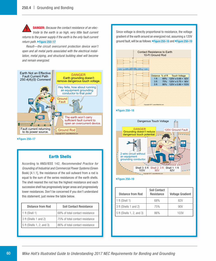
Since voltage is directly proportional to resistance, the voltage gradient of the earth around an energized rod, assuming a 120V ground fault, will be as follows: }Figure 250–18 and }Figure 250–19
Distance from RodSoil Contact Resistance Voltage Gradient
1 ft (Shell 1) 68% 82V
3 ft (Shells 1 and 2) 75% 90V
5 ft (Shells 1, 2, and 3) 86% 103V
DANGER: Because the contact resistance of an elec-trode to the earth is so high, very little fault current
returns to the power supply if the earth is the only fault current return path. }Figure 250–17
Result—the circuit overcurrent protection device won’t open and all metal parts associated with the electrical instal-lation, metal piping, and structural building steel will become and remain energized.
Volts
90
0.09
Am
ps
PVC PVC
4.8
Am
ps
Copyright 2017, www.MikeHolt.com
DANGEREarth grounding doesn’t
remove dangerous touch voltage.
Earth Not an EffectiveFault Current Path
250.4(A)(5) Comment
GroundFault
Fault current returningto its power source.
Hey fella, how about runningan equipment groundingconductor to that pole!
The earth won’t carrysufficient fault current toopen an overcurrent device.
Ground Rod
}Figure 250–17
Earth Shells
According to ANSI/IEEE 142, Recommended Practice for Grounding of Industrial and Commercial Power Systems (Green Book) [4.1.1], the resistance of the soil outward from a rod is equal to the sum of the series resistances of the earth shells. The shell nearest the rod has the highest resistance and each successive shell has progressively larger areas and progressively lower resistances. Don’t be concerned if you don’t understand this statement; just review the table below.
Distance from Rod Soil Contact Resistance
1 ft (Shell 1) 68% of total contact resistance
3 ft (Shells 1 and 2) 75% of total contact resistance
5 ft (Shells 1, 2, and 3) 86% of total contact resistance
Contact Resistance to Earth10-Ft Ground Rod
Copyright 2017, www.MikeHolt.com
1 Ft 1 Ft3 Ft 3 Ft5 Ft 5 Ft
Distance
1 ft
3 ft
5 ft
% of R
68%
75%
86%
Touch Voltage
120V x 0.68 = 82V
120V x 0.75 = 90V
120V x 0.86 = 103V
}Figure 250–18
Volts
0
Shell 1: 1 ft82V
Shell 2: 3 ft90V
Shell 3: 5 ft103V
2-wire circuit withoutan equipmentgrounding conductor.
Volts
90
120V Ground Fault
Volts
90
DANGERGrounding doesn’t reducedangerous touch potential.
Dangerous Touch Voltage
Copyright 2017, www.MikeHolt.com
}Figure 250–19
Mike Holt Enterprises • www.MikeHolt.com • 888.NEC.CODE (632.2633) 61
Grounding and Bonding | 250.4
(2) Equipment Bonding. Metal parts of electrical raceways, cables, enclosures, or equipment must be bonded together in a manner that creates a low-impedance path for ground-fault current to facilitate the operation of the circuit overcurrent protection device. }Figure 250–22
The fault current path must be capable of safely carrying the maximum ground-fault current likely to be imposed on it from any point on the wiring system should a ground fault occur to the electrical supply source.
(3) Bonding Conductive Materials. Conductive materials such as metal water piping systems, metal sprinkler piping, metal gas piping, and other metal-piping systems, as well as exposed structural steel members
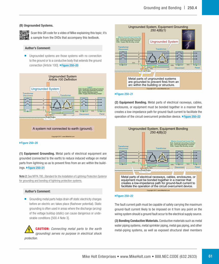
(B) Ungrounded Systems.
Scan this QR code for a video of Mike explaining this topic; it’s a sample from the DVDs that accompany this textbook.
Author’s Comment:
nUngrounded systems are those systems with no connection to the ground or to a conductive body that extends the ground connection [Article 100]. }Figure 250–20
(1) Equipment Grounding. Metal parts of electrical equipment are grounded (connected to the earth) to reduce induced voltage on metal parts from lightning so as to prevent fires from an arc within the build-ings. }Figure 250–21
Note 2: See NFPA 780, Standard for the Installation of Lightning Protection Systems
for grounding and bonding of lightning protection systems.
Author’s Comment:
nGrounding metal parts helps drain off static electricity charges before an electric arc takes place (flashover potential). Static grounding is often used in areas where the discharge (arcing) of the voltage buildup (static) can cause dangerous or unde-sirable conditions [500.4 Note 3].
CAUTION: Connecting metal parts to the earth (grounding) serves no purpose in electrical shock
protection.
Transformer
Disconnect
TransformerDisconnect
Panel
Copyright 2017, www.MikeHolt.com
SSBJ
GEC
EGC
EGC
EGC: Equipment Grounding Conductor: Grounding Electrode ConductorGEC
: System Bonding JumperSBJ: Supply-Side Bonding JumperSSBJ
Legend
Ungrounded System
A system not connected to earth (ground).
Ungrounded SystemArticle 100 Definition
}Figure 250–20
Transformer
Disconnect
TransformerDisconnect
Panel
Copyright 2017, www.MikeHolt.com
SSBJ
GEC
EGC
EGC
Ungrounded SystemEGC: Equipment Grounding Conductor
: Grounding Electrode ConductorGEC: Supply-Side Bonding JumperSSBJ
Effective Ground-Fault Current Path
Ungrounded System, Equipment Grounding250.4(B)(1)
Metal parts of ungrounded systemsare grounded to prevent fires from anarc within the building or structure.
}Figure 250–21
Transformer
Disconnect
TransformerDisconnect
Panel
Copyright 2017, www.MikeHolt.com
SSBJ
GEC
EGC
EGC
EGC: Equipment Grounding Conductor: Grounding Electrode ConductorGEC: Supply-Side Bonding JumperSSBJ
Effective Ground-Fault Current Path
Ungrounded System, Equipment Bonding250.4(B)(2)
Metal parts of electrical raceways, cables, enclosures, orequipment must be bonded together in a manner thatcreates a low-impedance path for ground-fault current tofacilitate the operation of the circuit overcurrent device.
}Figure 250–22

Mike Holt’s Illustrated Guide to Understanding 2017 NEC Requirements for Bonding and Grounding 62
250.6 | Grounding and Bonding
Author’s Comment:
nA single ground fault can’t be cleared on an ungrounded system because there’s no low-impedance fault current path to the electric power source. The first ground fault simply grounds the system and initiates the ground detector. However, a second ground fault on a different phase results in a line-to-line short circuit between the two ground faults. The conductive path, between the ground faults, provides the low-impedance fault current path necessary so the overcurrent protection device will open.
250.6 Objectionable Current
(A) Preventing Objectionable Current. To prevent a fire, electric shock, or improper operation of circuit overcurrent protection devices or elec-tronic equipment, electrical systems and equipment must be installed in a manner that prevents objectionable neutral current from flowing on metal parts. }Figure 250–25
(B) Stopping Objectionable Current. If the use of multiple grounding connections results in objectionable current and the requirements of 250.4(A)(5) or (B)(4) are met, one or more of the following alterations are permitted:
(1) Discontinue one or more but not all of such grounding connections.
(2) Change the locations of the grounding connections.
(3) Interrupt the continuity of the conductor or conductive path causing the objectionable current.
2017CC
likely to become energized must be bonded together in a manner that creates a low-impedance fault current path that’s capable of carrying the maximum fault current likely to be imposed on it. }Figure 250–23
Author’s Comment:
nThe phrase “likely to become energized” is subject to inter-pretation by the authority having jurisdiction.
(4) Fault Current Path. Electrical equipment, wiring, and other electri-cally conductive material likely to become energized must be installed in a manner that creates a low-impedance fault current path to facil-itate the operation of overcurrent protection devices should a second ground fault from a different phase occur. }Figure 250–24
M
1
5
2
6
3
7
4 1
5
2
6
3
7
41
5
2
6
3
7
4
H1 H3H2
X1 X3 XOX2
ON
OFF
INTERRUPTING RATING
MAX AMPS. R.M.S.
10,000 .SYM
VOLTS
120/240
V.A.C.
WARNING
Arc Flash and Shock Hazard
Appropriate RequiredPPE
Available Fault Current:
Installation Date:
01/01/2011
9,500 Amps
Ungrounded SystemBonding Electrically Conductive Materials
250.4(B)(3)
Water PipingExposedStructural
Steel
Gas PipingSprinkler Piping
Compressed Air
Copyright 2017, www.MikeHolt.com
Conductive materials must be bonded together in amanner that creates a low-impedance fault currentpath that’s capable of carrying the maximum faultcurrent likely to be imposed on it.
}Figure 250–23
SecondGround Fault
Volts480
The overcurrent deviceopens because of aline-to-line short circuit.
Electrical equipment must be bonded together tocreate a low-impedance fault current path to facilitatethe operation of overcurrent devices should a secondground fault from a different phase occur.
FirstGroundFault
Copyright 2017, www.MikeHolt.com
Ungrounded SystemFault Current Path
250.4(B)(4)
}Figure 250–24
Objectionable Current250.6(A)
Copyright 2017, www.MikeHolt.com
Electrical systems andequipment must be installedin a manner that preventsobjectionable neutral currentfrom flowing on metal parts.
}Figure 250–25
Mike Holt Enterprises • www.MikeHolt.com • 888.NEC.CODE (632.2633) 63
Grounding and Bonding | 250.6
(4) Take other suitable remedial and approved action.
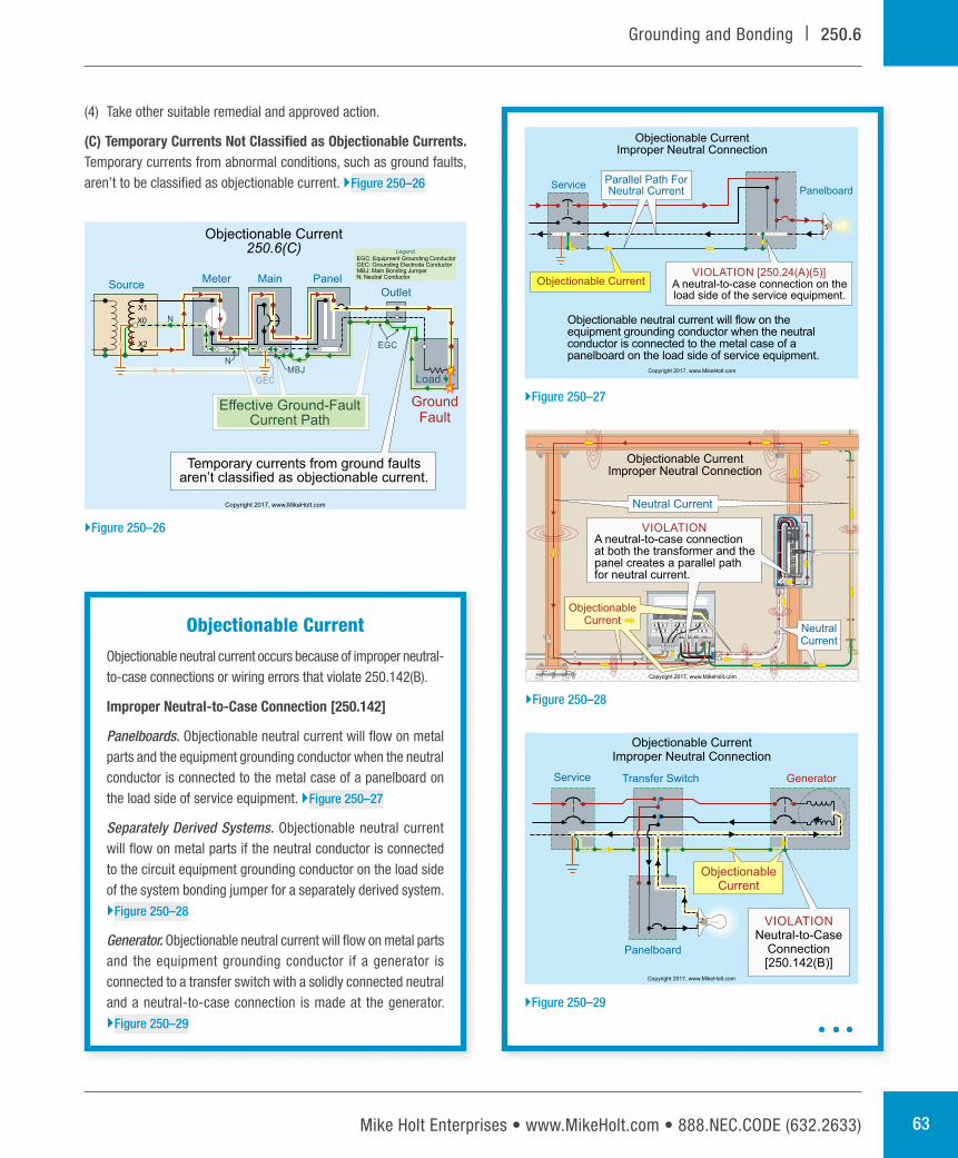
(C) Temporary Currents Not Classified as Objectionable Currents. Temporary currents from abnormal conditions, such as ground faults, aren’t to be classified as objectionable current. }Figure 250–26
Objectionable Current250.6(C)
Meter
X1
X2
X0
Main
Outlet
Load
PanelSource
GroundFault
MBJN
N
EGC
Copyright 2017, www.MikeHolt.com
Effective Ground-FaultCurrent Path
EGC: Equipment Grounding ConductorGEC: Grounding Electrode Conductor
: Main Bonding JumperMBJN: Neutral Conductor
Legend
GEC
Temporary currents from ground faultsaren’t classified as objectionable current.
}Figure 250–26
Objectionable Current
Objectionable neutral current occurs because of improper neutral- to-case connections or wiring errors that violate 250.142(B).
Improper Neutral-to-Case Connection [250.142]
Panelboards. Objectionable neutral current will flow on metal parts and the equipment grounding conductor when the neutral conductor is connected to the metal case of a panelboard on the load side of service equipment. }Figure 250–27
Separately Derived Systems. Objectionable neutral current will flow on metal parts if the neutral conductor is connected to the circuit equipment grounding conductor on the load side of the system bonding jumper for a separately derived system. }Figure 250–28
Generator. Objectionable neutral current will flow on metal parts and the equipment grounding conductor if a generator is connected to a transfer switch with a solidly connected neutral and a neutral-to-case connection is made at the generator. }Figure 250–29
Objectionable CurrentImproper Neutral Connection
ServicePanelboard
A neutral-to-case connection on theload side of the service equipment.
VIOLATION [250.24(A)(5)]Objectionable Current
Copyright 2017, www.MikeHolt.com
Objectionable neutral current will flow on theequipment grounding conductor when the neutralconductor is connected to the metal case of apanelboard on the load side of service equipment.
Parallel Path ForNeutral Current
}Figure 250–27
1
5
2
6
3
7
4 1
5
2
6
3
7
41
5
2
6
3
7
4
X1 X3 XOX2
H1 H3H2
ON
OFF
INTERRUPTING RATING
MAX AMPS. R.M.S.
10,000 .SYM
VOLTS
120/240
V.A.C.
Objectionable CurrentImproper Neutral Connection
Neutral Current
ObjectionableCurrent
A neutral-to-case connectionat both the transformer and thepanel creates a parallel pathfor neutral current.
VIOLATION
NeutralCurrent
Copyright 2017, www.MikeHolt.com
}Figure 250–28
ObjectionableCurrent
VIOLATIONNeutral-to-Case
Connection[250.142(B)]
Service
Panelboard
Transfer Switch Generator
Objectionable CurrentImproper Neutral Connection
Copyright 2017, www.MikeHolt.com
}Figure 250–29

Mike Holt’s Illustrated Guide to Understanding 2017 NEC Requirements for Bonding and Grounding 64
250.6 | Grounding and Bonding
• A 230V time-clock motor is replaced with a 115V time- clock motor, and the circuit equipment grounding conductor is used for neutral return current.
• A 115V water filter is wired to a 240V well-pump motor circuit, and the circuit equipment grounding conductor is used for neutral return current. }Figure 250–32
• The circuit equipment grounding conductor is used for neutral return current. }Figure 250–33
Disconnects. Objectionable neutral current will flow on metal parts and the equipment grounding conductor when the neutral conductor is connected to the metal case of a disconnect that’s not part of the service equipment. }Figure 250–30
Wiring Errors. Objectionable neutral current will flow on metal parts and equipment grounding conductors when the neutral conductor from one system is used as the neutral conductor for a different system. }Figure 250–31
Objectionable neutral current will flow on the equipment grounding conductor when the circuit equipment grounding conductor is used as a neutral conductor such as where:
SeparateBuilding
KILOWATTHOURS
6 03 9
KILOWATTHOURS
6 03 9
ON
OFF
Objectionable CurrentSeparate Buildings or Structures
An improper neutral-to-caseconnection causes dangerousneutral current on metal parts.
VIOLATION
ParallelNeutralCurrentPaths
WARNING
Arc Flash and Shock Hazard
Appropriate RequiredPPE
Available Fault Current:
Installation Date:
01/01/2011
9,500 Amps
The equipment grounding conductor andmetal water pipe carry neutral current.
WARNING
Arc Flash and Shock Hazard
Appropriate RequiredPPE
WARNING
Arc Flash and Shock Hazard
Appropriate RequiredPPE
Copyright 2017, www.MikeHolt.com
}Figure 250–30
277/480VPanelboard
Objectionable CurrentNeutral Wiring Error
H3H2H1 X3 X0X2X1
Circuit Breakeris OFF
DANGER: The 120/208V panelboard (de-energized)can have dangerous voltage from the 277V lightingcircuit because of the crossed neutrals.
ObjectionableCurrent
277V
120/208VPanelboard
CrossedNeutrals
Copyright 2017, www.MikeHolt.com
}Figure 250–31
Panelboard
230VPumpMotor
Pump MotorDisconnect
Neutral Current onthe Equipment
Grounding Conductor
The 115V water filter uses the equipmentgrounding conductor for neutral current.
VIOLATION 115VWater Filter
Objectionable Currentas the Neutral ConductorEGC
Copyright 2017, www.MikeHolt.com
}Figure 250–32
Objectionable Current, as Neutral ConductorEGC
OFF
OF
F
Neutral Current onEquipment Grounding
Conductor
Existing Installation:1-Pole Switch
1 2
A 1-pole switch replaced with acombination switch-receptacle.
Copyright 2017, www.MikeHolt.com
}Figure 250–33
Mike Holt Enterprises • www.MikeHolt.com • 888.NEC.CODE (632.2633) 65
Grounding and Bonding | 250.6
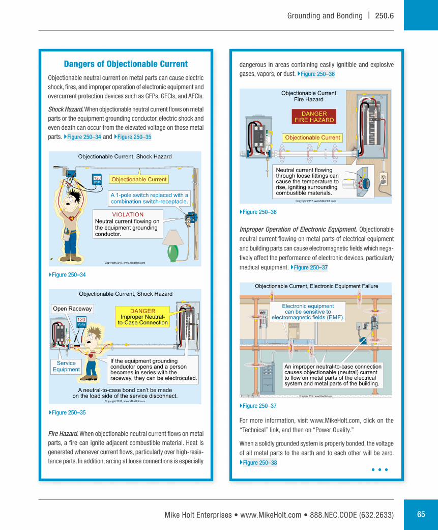
dangerous in areas containing easily ignitible and explosive gases, vapors, or dust. }Figure 250–36
Improper Operation of Electronic Equipment. Objectionable neutral current flowing on metal parts of electrical equipment and building parts can cause electromagnetic fields which nega-tively affect the performance of electronic devices, particularly medical equipment. }Figure 250–37
For more information, visit www.MikeHolt.com, click on the “Technical” link, and then on “Power Quality.”
When a solidly grounded system is properly bonded, the voltage of all metal parts to the earth and to each other will be zero. }Figure 250–38
Dangers of Objectionable CurrentObjectionable neutral current on metal parts can cause electric shock, fires, and improper operation of electronic equipment and overcurrent protection devices such as GFPs, GFCIs, and AFCIs.
Shock Hazard. When objectionable neutral current flows on metal parts or the equipment grounding conductor, electric shock and even death can occur from the elevated voltage on those metal parts. }Figure 250–34 and }Figure 250–35
Fire Hazard. When objectionable neutral current flows on metal parts, a fire can ignite adjacent combustible material. Heat is generated whenever current flows, particularly over high-resis-tance parts. In addition, arcing at loose connections is especially
OF
F
A 1-pole switch replaced with acombination switch-receptacle.
Volts120
Objectionable Current, Shock Hazard
VIOLATION
Neutral current flowing onthe equipment groundingconductor.
Objectionable Current
Copyright 2017, www.MikeHolt.com
}Figure 250–34
A neutral-to-case bond can’t be madeon the load side of the service disconnect.
Objectionable Current, Shock Hazard
ServiceEquipment
Open Raceway
If the equipment groundingconductor opens and a personbecomes in series with theraceway, they can be electrocuted.
DANGERImproper Neutral-
to-Case ConnectionVolts
120
Copyright 2017, www.MikeHolt.com
}Figure 250–35
Neutral current flowingthrough loose fittings cancause the temperature torise, igniting surroundingcombustible materials.
DANGERFIRE HAZARD
Objectionable Current
Objectionable CurrentFire Hazard
Copyright 2017, www.MikeHolt.com
}Figure 250–36
ON
OFF
INTERRUPTING RATING
MAX AMPS. R.M.S.10,000 .SYM
VOLTS120/240V.A.C.
HandOffAuto
Service Equipment
Electronic equipmentcan be sensitive to
electromagnetic fields ( ).EMF
Objectionable Current, Electronic Equipment Failure
Copyright 2017, www.MikeHolt.com
An improper neutral-to-case connectioncauses objectionable (neutral) currentto flow on metal parts of the electricalsystem and metal parts of the building.
WARNING
Arc Flash and Shock Hazard
Appropriate RequiredPPE
Available Fault Current:
Installation Date:
}Figure 250–37
Mike Holt’s Illustrated Guide to Understanding 2017 NEC Requirements for Bonding and Grounding 66
250.8 | Grounding and Bonding
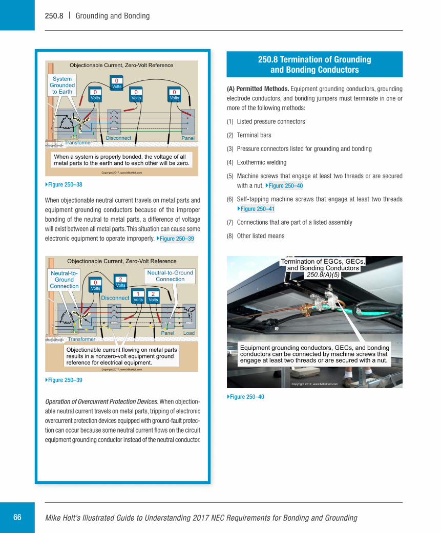
250.8 Termination of Grounding and Bonding Conductors
(A) Permitted Methods. Equipment grounding conductors, grounding electrode conductors, and bonding jumpers must terminate in one or more of the following methods:
(1) Listed pressure connectors
(2) Terminal bars
(3) Pressure connectors listed for grounding and bonding
(4) Exothermic welding
(5) Machine screws that engage at least two threads or are secured with a nut, }Figure 250–40
(6) Self-tapping machine screws that engage at least two threads }Figure 250–41
(7) Connections that are part of a listed assembly
(8) Other listed means
When objectionable neutral current travels on metal parts and equipment grounding conductors because of the improper bonding of the neutral to metal parts, a difference of voltage will exist between all metal parts. This situation can cause some electronic equipment to operate improperly. }Figure 250–39
Operation of Overcurrent Protection Devices. When objection-able neutral current travels on metal parts, tripping of electronic overcurrent protection devices equipped with ground-fault protec-tion can occur because some neutral current flows on the circuit equipment grounding conductor instead of the neutral conductor.
TransformerDisconnect Panel
Volts
0SystemGroundedto Earth
Objectionable Current, Zero-Volt Reference
Volts
0Volts
0Volts
0
When a system is properly bonded, the voltage of allmetal parts to the earth and to each other will be zero.
Copyright 2017, www.MikeHolt.com
}Figure 250–38
Transformer
Disconnect
Panel Load
Objectionable Current, Zero-Volt Reference
Volts
2Volts
1
Neutral-to-Ground
Connection
Neutral-to-GroundConnection
Objectionable current flowing on metal partsresults in a nonzero-volt equipment groundreference for electrical equipment.
Volts
2
Volts
0
Copyright 2017, www.MikeHolt.com
}Figure 250–39
Equipment grounding conductors, s, and bondingGECconductors can be connected by machine screws thatengage at least two threads or are secured with a nut.
Termination of s, s,EGC GECand Bonding Conductors
250.8(A)(5)
Copyright 2017, www.MikeHolt.com
}Figure 250–40