Embed Size (px)
Citation preview
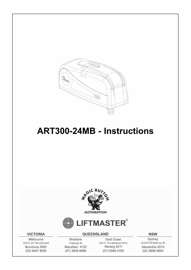
ART300-24MB - Instructions
1
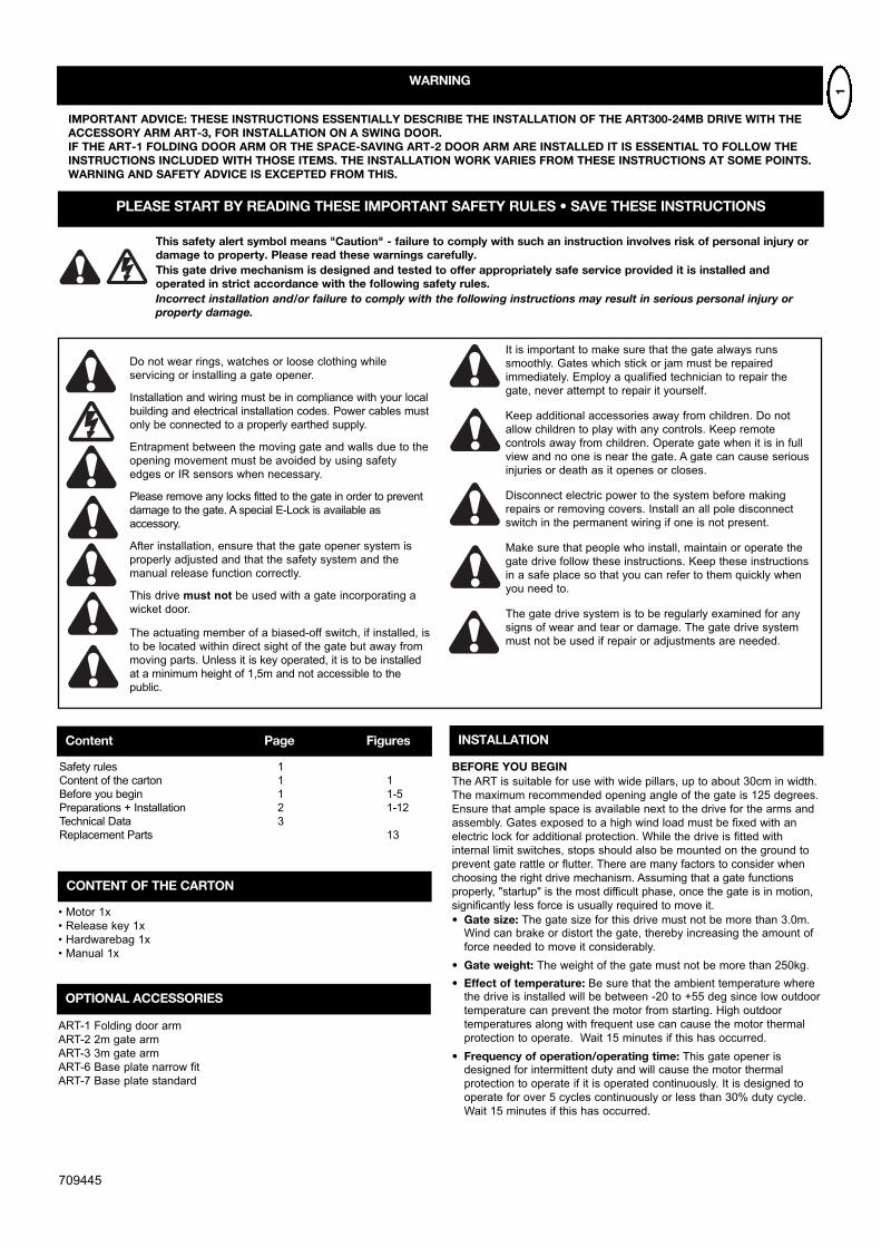
Do not wear rings, watches or loose clothing while
servicing or installing a gate opener.
Installation and wiring must be in compliance with your local
building and electrical installation codes. Power cables must
only be connected to a properly earthed supply.
Entrapment between the moving gate and walls due to the
opening movement must be avoided by using safety
edges or IR sensors when necessary.
Please remove any locks fitted to the gate in order to prevent
damage to the gate. A special E-Lock is available as
accessory.
After installation, ensure that the gate opener system is
properly adjusted and that the safety system and the
manual release function correctly.
This drive must not be used with a gate incorporating a
wicket door.
The actuating member of a biased-off switch, if installed, is
to be located within direct sight of the gate but away from
moving parts. Unless it is key operated, it is to be installed
at a minimum height of 1,5m and not accessible to the
public.
It is important to make sure that the gate always runs
smoothly. Gates which stick or jam must be repaired
immediately. Employ a qualified technician to repair the
gate, never attempt to repair it yourself.
Keep additional accessories away from children. Do not
allow children to play with any controls. Keep remote
controls away from children. Operate gate when it is in full
view and no one is near the gate. A gate can cause serious
injuries or death as it openes or closes.
Disconnect electric power to the system before making
repairs or removing covers. Install an all pole disconnect
switch in the permanent wiring if one is not present.
Make sure that people who install, maintain or operate the
gate drive follow these instructions. Keep these instructions
in a safe place so that you can refer to them quickly when
you need to.
The gate drive system is to be regularly examined for any
signs of wear and tear or damage. The gate drive system
must not be used if repair or adjustments are needed.
This safety alert symbol means "Caution" - failure to comply with such an instruction involves risk of personal injury ordamage to property. Please read these warnings carefully.This gate drive mechanism is designed and tested to offer appropriately safe service provided it is installed andoperated in strict accordance with the following safety rules.Incorrect installation and/or failure to comply with the following instructions may result in serious personal injury orproperty damage.
709445
PLEASE START BY READING THESE IMPORTANT SAFETY RULES • SAVE THESE INSTRUCTIONS
Content Page Figures
Safety rules 1
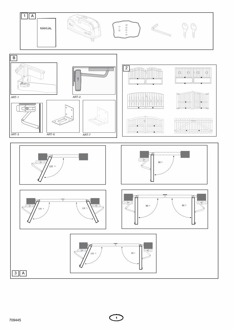
Content of the carton 1 1
Before you begin 1 1-5
Preparations + Installation 2 1-12
Technical Data 3
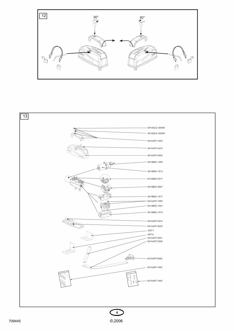
Replacement Parts 13
CONTENT OF THE CARTON
• Motor 1x
• Release key 1x
• Hardwarebag 1x
• Manual 1x
INSTALLATION
BEFORE YOU BEGINThe ART is suitable for use with wide pillars, up to about 30cm in width.
The maximum recommended opening angle of the gate is 125 degrees.
Ensure that ample space is available next to the drive for the arms and
assembly. Gates exposed to a high wind load must be fixed with an
electric lock for additional protection. While the drive is fitted with
internal limit switches, stops should also be mounted on the ground to
prevent gate rattle or flutter. There are many factors to consider when
choosing the right drive mechanism. Assuming that a gate functions
properly, "startup" is the most difficult phase, once the gate is in motion,
significantly less force is usually required to move it.
• Gate size: The gate size for this drive must not be more than 3.0m.Wind can brake or distort the gate, thereby increasing the amount of
force needed to move it considerably.
• Gate weight: The weight of the gate must not be more than 250kg.
• Effect of temperature: Be sure that the ambient temperature wherethe drive is installed will be between -20 to +55 deg since low outdoor
temperature can prevent the motor from starting. High outdoor
temperatures along with frequent use can cause the motor thermal
protection to operate. Wait 15 minutes if this has occurred.
• Frequency of operation/operating time: This gate opener isdesigned for intermittent duty and will cause the motor thermal
protection to operate if it is operated continuously. It is designed to
operate for over 5 cycles continuously or less than 30% duty cycle.
Wait 15 minutes if this has occurred.
IMPORTANT ADVICE: THESE INSTRUCTIONS ESSENTIALLY DESCRIBE THE INSTALLATION OF THE ART300-24MB DRIVE WITH THEACCESSORY ARM ART-3, FOR INSTALLATION ON A SWING DOOR.IF THE ART-1 FOLDING DOOR ARM OR THE SPACE-SAVING ART-2 DOOR ARM ARE INSTALLED IT IS ESSENTIAL TO FOLLOW THEINSTRUCTIONS INCLUDED WITH THOSE ITEMS. THE INSTALLATION WORK VARIES FROM THESE INSTRUCTIONS AT SOME POINTS.WARNING AND SAFETY ADVICE IS EXCEPTED FROM THIS.
WARNING
OPTIONAL ACCESSORIES
ART-1 Folding door arm
ART-2 2m gate arm
ART-3 3m gate arm
ART-6 Base plate narrow fit
ART-7 Base plate standard
2
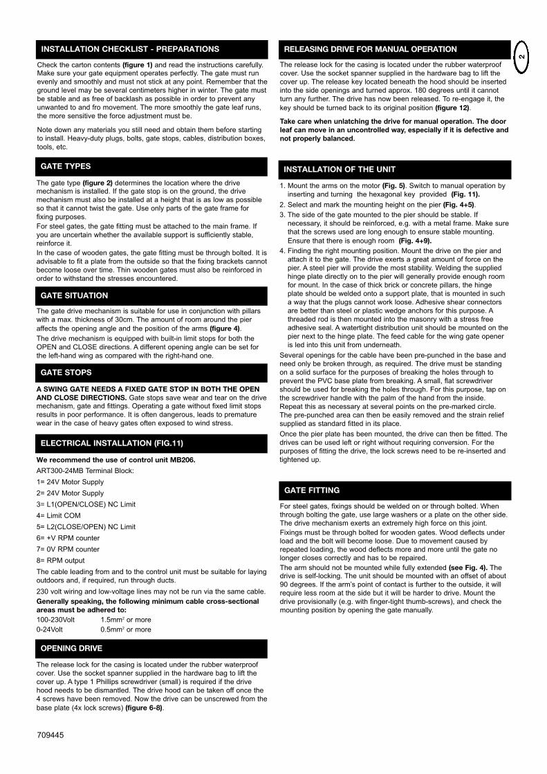
INSTALLATION CHECKLIST - PREPARATIONS
Check the carton contents (figure 1) and read the instructions carefully.Make sure your gate equipment operates perfectly. The gate must run
evenly and smoothly and must not stick at any point. Remember that the
ground level may be several centimeters higher in winter. The gate must
be stable and as free of backlash as possible in order to prevent any
unwanted to and fro movement. The more smoothly the gate leaf runs,
the more sensitive the force adjustment must be.
Note down any materials you still need and obtain them before starting
to install. Heavy-duty plugs, bolts, gate stops, cables, distribution boxes,
tools, etc.
GATE TYPES
The gate type (figure 2) determines the location where the drivemechanism is installed. If the gate stop is on the ground, the drive
mechanism must also be installed at a height that is as low as possible
so that it cannot twist the gate. Use only parts of the gate frame for
fixing purposes.
For steel gates, the gate fitting must be attached to the main frame. If
you are uncertain whether the available support is sufficiently stable,
reinforce it.
In the case of wooden gates, the gate fitting must be through bolted. It is
advisable to fit a plate from the outside so that the fixing brackets cannot
become loose over time. Thin wooden gates must also be reinforced in
order to withstand the stresses encountered.
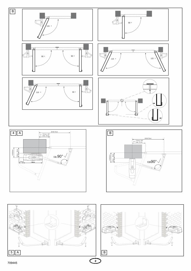
GATE SITUATION
The gate drive mechanism is suitable for use in conjunction with pillars
with a max. thickness of 30cm. The amount of room around the pier
affects the opening angle and the position of the arms (figure 4). The drive mechanism is equipped with built-in limit stops for both the
OPEN and CLOSE directions. A different opening angle can be set for
the left-hand wing as compared with the right-hand one.
GATE STOPS
A SWING GATE NEEDS A FIXED GATE STOP IN BOTH THE OPENAND CLOSE DIRECTIONS. Gate stops save wear and tear on the drivemechanism, gate and fittings. Operating a gate without fixed limit stops
results in poor performance. It is often dangerous, leads to premature
wear in the case of heavy gates often exposed to wind stress.
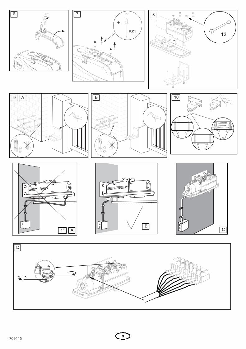
ELECTRICAL INSTALLATION (FIG.11)
We recommend the use of control unit MB206.
ART300-24MB Terminal Block:
1= 24V Motor Supply
2= 24V Motor Supply
3= L1(OPEN/CLOSE) NC Limit
4= Limit COM
5= L2(CLOSE/OPEN) NC Limit
6= +V RPM counter
7= 0V RPM counter
8= RPM output
The cable leading from and to the control unit must be suitable for laying
outdoors and, if required, run through ducts.
230 volt wiring and low-voltage lines may not be run via the same cable.
Generally speaking, the following minimum cable cross-sectionalareas must be adhered to:100-230Volt 1.5mm2 or more
0-24Volt 0.5mm2 or more
RELEASING DRIVE FOR MANUAL OPERATION
The release lock for the casing is located under the rubber waterproof
cover. Use the socket spanner supplied in the hardware bag to lift the
cover up. The release key located beneath the hood should be inserted
into the side openings and turned approx. 180 degrees until it cannot
turn any further. The drive has now been released. To re-engage it, the
key should be turned back to its original position (figure 12).
Take care when unlatching the drive for manual operation. The door
leaf can move in an uncontrolled way, especially if it is defective and
not properly balanced.
INSTALLATION OF THE UNIT
1. Mount the arms on the motor (Fig. 5). Switch to manual operation by
inserting and turning the hexagonal key provided (Fig. 11).2. Select and mark the mounting height on the pier (Fig. 4+5).3. The side of the gate mounted to the pier should be stable. If
necessary, it should be reinforced, e.g. with a metal frame. Make sure
that the screws used are long enough to ensure stable mounting.
Ensure that there is enough room (Fig. 4+9).4. Finding the right mounting position. Mount the drive on the pier and
attach it to the gate. The drive exerts a great amount of force on the
pier. A steel pier will provide the most stability. Welding the supplied
hinge plate directly on to the pier will generally provide enough room
for mount. In the case of thick brick or concrete pillars, the hinge
plate should be welded onto a support plate, that is mounted in such
a way that the plugs cannot work loose. Adhesive shear connectors
are better than steel or plastic wedge anchors for this purpose. A
threaded rod is then mounted into the masonry with a stress free
adhesive seal. A watertight distribution unit should be mounted on the
pier next to the hinge plate. The feed cable for the wing gate opener
is led into this unit from underneath.
Several openings for the cable have been pre-punched in the base and
need only be broken through, as required. The drive must be standing
on a solid surface for the purposes of breaking the holes through to
prevent the PVC base plate from breaking. A small, flat screwdriver
should be used for breaking the holes through. For this purpose, tap on
the screwdriver handle with the palm of the hand from the inside.
Repeat this as necessary at several points on the pre-marked circle.
The pre-punched area can then be easily removed and the strain relief
supplied as standard fitted in its place.
Once the pier plate has been mounted, the drive can then be fitted. The
drives can be used left or right without requiring conversion. For the
purposes of fitting the drive, the lock screws need to be re-inserted and
tightened up.
709445
OPENING DRIVE
The release lock for the casing is located under the rubber waterproof
cover. Use the socket spanner supplied in the hardware bag to lift the
cover up. A type 1 Phillips screwdriver (small) is required if the drive
hood needs to be dismantled. The drive hood can be taken off once the
4 screws have been removed. Now the drive can be unscrewed from the
base plate (4x lock screws) (figure 6-8).
GATE FITTING
For steel gates, fixings should be welded on or through bolted. When
through bolting the gate, use large washers or a plate on the other side.
The drive mechanism exerts an extremely high force on this joint.
Fixings must be through bolted for wooden gates. Wood deflects under
load and the bolt will become loose. Due to movement caused by
repeated loading, the wood deflects more and more until the gate no
longer closes correctly and has to be repaired.
The arm should not be mounted while fully extended (see Fig. 4). Thedrive is self-locking. The unit should be mounted with an offset of about
90 degrees. If the arm’s point of contact is further to the outside, it will
require less room at the side but it will be harder to drive. Mount the
drive provisionally (e.g. with finger-tight thumb-screws), and check the
mounting position by opening the gate manually.
3
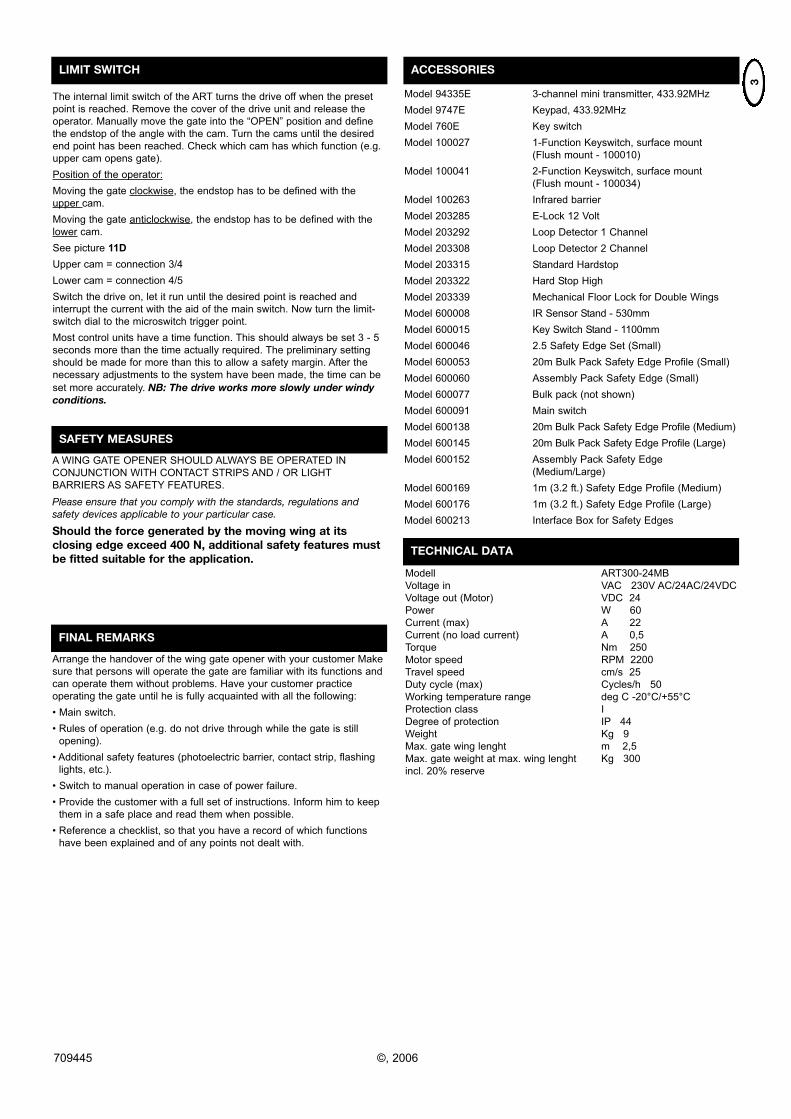
LIMIT SWITCH
The internal limit switch of the ART turns the drive off when the preset
point is reached. Remove the cover of the drive unit and release the
operator. Manually move the gate into the “OPEN” position and define
the endstop of the angle with the cam. Turn the cams until the desired
end point has been reached. Check which cam has which function (e.g.
upper cam opens gate).
Position of the operator:
Moving the gate clockwise, the endstop has to be defined with the
upper cam.
Moving the gate anticlockwise, the endstop has to be defined with the
lower cam.
See picture 11D
Upper cam = connection 3/4
Lower cam = connection 4/5
Switch the drive on, let it run until the desired point is reached and
interrupt the current with the aid of the main switch. Now turn the limit-
switch dial to the microswitch trigger point.
Most control units have a time function. This should always be set 3 - 5
seconds more than the time actually required. The preliminary setting
should be made for more than this to allow a safety margin. After the
necessary adjustments to the system have been made, the time can be
set more accurately. NB: The drive works more slowly under windyconditions.
SAFETY MEASURES
A WING GATE OPENER SHOULD ALWAYS BE OPERATED IN
CONJUNCTION WITH CONTACT STRIPS AND / OR LIGHT
BARRIERS AS SAFETY FEATURES.
Please ensure that you comply with the standards, regulations andsafety devices applicable to your particular case.
Should the force generated by the moving wing at itsclosing edge exceed 400 N, additional safety features mustbe fitted suitable for the application.
FINAL REMARKS
Arrange the handover of the wing gate opener with your customer Make
sure that persons will operate the gate are familiar with its functions and
can operate them without problems. Have your customer practice
operating the gate until he is fully acquainted with all the following:
• Main switch.
• Rules of operation (e.g. do not drive through while the gate is still
opening).
• Additional safety features (photoelectric barrier, contact strip, flashing
lights, etc.).
• Switch to manual operation in case of power failure.
• Provide the customer with a full set of instructions. Inform him to keep
them in a safe place and read them when possible.
• Reference a checklist, so that you have a record of which functions
have been explained and of any points not dealt with.
ACCESSORIES
Model 94335E 3-channel mini transmitter, 433.92MHz
Model 9747E Keypad, 433.92MHz
Model 760E Key switch
Model 100027 1-Function Keyswitch, surface mount
(Flush mount - 100010)
Model 100041 2-Function Keyswitch, surface mount
(Flush mount - 100034)
Model 100263 Infrared barrier
Model 203285 E-Lock 12 Volt
Model 203292 Loop Detector 1 Channel
Model 203308 Loop Detector 2 Channel
Model 203315 Standard Hardstop
Model 203322 Hard Stop High
Model 203339 Mechanical Floor Lock for Double Wings
Model 600008 IR Sensor Stand - 530mm
Model 600015 Key Switch Stand - 1100mm
Model 600046 2.5 Safety Edge Set (Small)
Model 600053 20m Bulk Pack Safety Edge Profile (Small)
Model 600060 Assembly Pack Safety Edge (Small)
Model 600077 Bulk pack (not shown)
Model 600091 Main switch
Model 600138 20m Bulk Pack Safety Edge Profile (Medium)
Model 600145 20m Bulk Pack Safety Edge Profile (Large)
Model 600152 Assembly Pack Safety Edge
(Medium/Large)
Model 600169 1m (3.2 ft.) Safety Edge Profile (Medium)
Model 600176 1m (3.2 ft.) Safety Edge Profile (Large)
Model 600213 Interface Box for Safety Edges
TECHNICAL DATA
Modell ART300-24MB
Voltage in VAC 230V AC/24AC/24VDC
Voltage out (Motor) VDC 24
Power W 60
Current (max) A 22
Current (no load current) A 0,5
Torque Nm 250
Motor speed RPM 2200
Travel speed cm/s 25
Duty cycle (max) Cycles/h 50
Working temperature range deg C -20°C/+55°C
Protection class I
Degree of protection IP 44
Weight Kg 9
Max. gate wing lenght m 2,5
Max. gate weight at max. wing lenght Kg 300
incl. 20% reserve
709445 ©, 2006
1709445
ART-1 ART-2
ART-3 ART-6 ART-7
115 o
90 o
90 o 90 o
115 o 115 o
115 o 90 o
1 A
B
2
3 A
2709445
115 o
90 o
90 o 90 o
115 o 115 o
115 o 90 o
A=3
8,5c
m
8,5c
m30
cm
C
B=60-70cm
ca.
7-8 cm = 90°max. 10 cm=
A=3
8,5c
m
8,5c
m30
cm
C
B=60-70cm
ca.
7-8 cm = 90°max. 10 cm=
B
4 A B
5 A B
3709445
+
6 7 8
9 A B 10
11 AB
C
D
4
ART-6
ART-7
13
709445 ©,2006
12