Embed Size (px)
DESCRIPTION
eng
Citation preview
Studia Geotechnica et Mechanica, Vol. XXXIV, No. 4, 2012 DOI: 10.5277/sgm041203
EFFICIENCY ASSESSMENT OF VERTICAL BARRIERSON THE BASIS OF FLOW AND TRANSPORT
NUMERICAL MODELING
EUGENIUSZ KODA, TOMASZ KOŁANKA, PIOTR OSIŃSKI
Department of Geotechnical Engineering, Warsaw University of Life Sciences – SGGW
Abstract: The construction of cut-off walls is a common solution applied in such disciplines as landreclamation and landfill containment. Most commonly the construction of vertical barriers is based oncut-off wall mono or diphase technology with the use of bentonite-cement mixture as a filling material.The content of the paper is focused on groundwater flow and transport numerical modeling conductedon landfill areas where vertical bentonite barriers were constructed. The modeling process was con-ducted with the use of FEMWATER software which employs analysis based on finite element method.There are two examples of the software application presented in the paper which concern such casestudies, i.e., reclamation of Radiowo and Łubna landfill sites. These examples are provided to prove thatthe appropriate investigation of ground conditions as well as definition of initial and boundary condi-tions and correct selection of material parameters to be fed into the software, are crucial for the overallmodeling process. Moreover, the comparison of results obtained from the numerical modeling and thegroundwater monitoring on site is presented for one of the case studies.
1. INTRODUCTION
Nowadays, the vertical barriers are constructed with the use of technologies mostcommonly based on deep foundation and ground reinforcement techniques [1]. Theapplication of cut-off wall appears to be a great solution as a part of the landfill sitereclamation process. The fundamental idea of cellular cut-offs is an isolating by usingscreen with linking cross wall at certain longitudinal distances [2]. It protects the sur-rounding environment against the pollutants transport and significantly decreases thelevel of soil and groundwater contamination. The selection process of appropriateconstruction technique depends on geological structure of the ground, durability andchemical resistance of the material used, also the ability of heavy machinery entranceat the site and economical factor have to be considered. Migration of the pollutantsdepends on geological conditions, which can be favourable to the transport of waterand the substances it carries (large thickness of permeable layers, high hydraulic gra-dients) or it can completely stop and keep the transport away from the landfill (im-permeable layers, low gradients).
The assessment of the vertical barrier influence on the migration of contaminantscould be conducted with the use of numerical analysis of advective transport [3], [4].The analysis of the modeling results is useful for a design of exact location of the ver-tical barrier and drainage system combined. The software that is commonly used formodeling of groundwater flow and transport is FEMWATER [5], [6]. It enables
E. KODA et al.28
building the model of existing hydrogeological conditions on the site (based on fieldinvestigation) for the further prediction of hydraulic conditions after introducing engi-neering works. The crucial part of building the model and making it reliable is theappropriate selection of data that is going to be fed into the software. The paperis going to prove that construction of bentonite cut off wall is a reliable method inlandfill reclamation process, and moreover it is shown how numerical modeling couldbe used to predict the behavior of groundwater flow in changed hydrogeological con-ditions.
2. BENTONITE VERTICAL BARRIERS ON RADIOWOAND ŁUBNA LANDFILLS
The most common cut-off wall constructing method is a technology of diaphragmwalls made of combined still elements. They are not recommended to be constructedon contaminated landfill sites as they are not resistant to the aggressive character oflandfill leachate. However, during the construction works this type of barriers isa reliable solution for temporary ground sealing. Another method of constructing cut-off walls with the use of jet-grouting technique is also quite frequently applied onsites. This type of structures is so called high-pressure vertical barriers. The method ofconstruction is based on auger equipped with a fluid jet introduced into the ground.The mixture of water, cement and air is injected under a high pressure into the ground.After hardening the material becomes practically impermeable. A disadvantage ofhigh-pressure vertical barriers is lack of injection depth and joints control, especiallywhen heterogeneous ground is considered. However, this type of method eliminatesthe problem of excavated soil management, which is a great advantage when isolatingcontaminated sites where impermeable layer is investigated at a significant depth [7].
The most appropriate cut-off wall construction method for contaminated site isola-tion is the one utilizing basic or complex mono phase diaphragm wall technique [8].During the excavation the sealing mixture being introduced into the ground provides thepit stability and after hardening it becomes an impermeable material protecting againstmigration of contaminants. However, for extremely contaminated sites complex verticalbarriers are recommended. The construction of cut-off wall utilizing mono phase dia-phragm wall technique has a one significant disadvantage, there is a huge amount ofcontaminated soil excavated that has to be properly managed and utilized only on land-fills [1]. Such solutions among others, allow extending time of landfill operation [9].
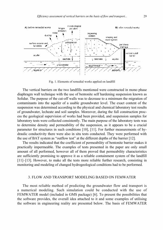
The examples of introducing solutions described above is the reclamation process ofRadiowo and Łubna landfills which consisted of bentonite cut-off wall construction onboundaries of the landfill body, leachate collecting drainage, degassing system, restora-tion of ditches, and landfill body engineering and bioengineering of landfill slopes. Thescheme of the landfill where remedial works were introduced is presented in Fig. 1.
Efficiency assessment of vertical barriers on the basis of flow and transport... 29
Fig. 1. Elements of remedial works applied on landfill
The vertical barriers on the two landfills mentioned were constructed in mono phasediaphragm wall technique with the use of bentonite self hardening suspension known asSolidur. The purpose of the cut-off walls was to decrease to a minimum the migration ofcontaminants into the aquifer of a usable groundwater level. The exact content of thesuspension was determined according to the physical and chemical laboratory test resultsof groundwater, lecheate and soil samples. Moreover, during the full construction proc-ess the geological supervision of works had been provided, and suspension samples forlaboratory tests were collected consistently. The main purpose of the laboratory tests wasto determine density and permeability of the suspension, as it appears to be a crucialparameter for structures in such conditions [10], [11]. For further measurements of hy-draulic conductivity there were also in situ tests conducted. They were performed withthe use of BAT system as “outflow test” at the different depths of the barrier [12].
The results indicated that the coefficient of permeability of bentonite barrier makes itpractically impermeable. The examples of tests presented in the paper are only smallamount of all performed, however all of them proved that permeability characteristicsare sufficiently promising to approve it as a reliable containment system of the landfill[11]–[13]. However, to make all the tests more reliable further research, consisting inmonitoring and modeling of changed hydrogeological conditions had to be performed.
3. FLOW AND TRANSPORT MODELING BASED ON FEMWATER
The most reliable method of predicting the groundwater flow and transport isa numerical modeling. Such simulation could be conducted with the use ofFEMWATER model (included in GMS package) [6]. To present the possibilities thatthe software provides, the overall idea attached to it and some examples of utilisingthe software in engineering reality are presented below. The basis of FEMWATER
E. KODA et al.30
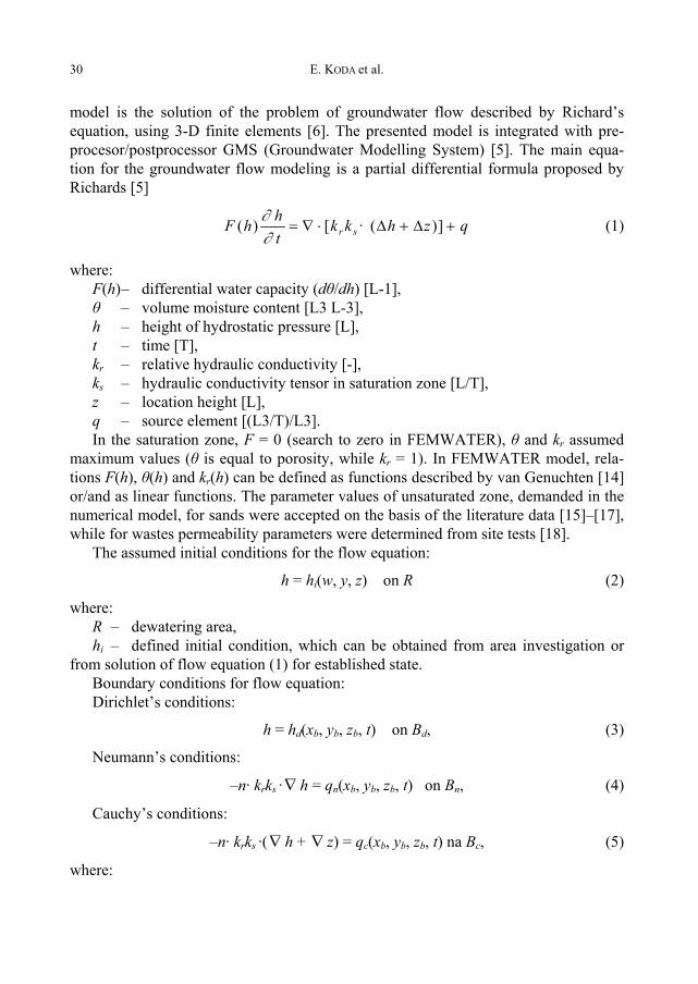
model is the solution of the problem of groundwater flow described by Richard’sequation, using 3-D finite elements [6]. The presented model is integrated with pre-procesor/postprocessor GMS (Groundwater Modelling System) [5]. The main equa-tion for the groundwater flow modeling is a partial differential formula proposed byRichards [5]
qzhkkthhF sr +Δ+Δ⋅∇= ])( ·[)(
∂∂ (1)
where:F(h)– differential water capacity (dθ/dh) [L-1],θ – volume moisture content [L3 L-3],h – height of hydrostatic pressure [L],t – time [T],kr – relative hydraulic conductivity [-],ks – hydraulic conductivity tensor in saturation zone [L/T],z – location height [L],q – source element [(L3/T)/L3].In the saturation zone, F = 0 (search to zero in FEMWATER), θ and kr assumed
maximum values (θ is equal to porosity, while kr = 1). In FEMWATER model, rela-tions F(h), θ(h) and kr(h) can be defined as functions described by van Genuchten [14]or/and as linear functions. The parameter values of unsaturated zone, demanded in thenumerical model, for sands were accepted on the basis of the literature data [15]–[17],while for wastes permeability parameters were determined from site tests [18].
The assumed initial conditions for the flow equation:
h = hi(w, y, z) on R (2)
where:R – dewatering area,hi – defined initial condition, which can be obtained from area investigation or
from solution of flow equation (1) for established state.Boundary conditions for flow equation:Dirichlet’s conditions:
h = hd(xb, yb, zb, t) on Bd, (3)
Neumann’s conditions:
–n· krks ·∇ h = qn(xb, yb, zb, t) on Bn, (4)
Cauchy’s conditions:
–n· krks ·(∇ h + ∇ z) = qc(xb, yb, zb, t) na Bc, (5)
where:
Efficiency assessment of vertical barriers on the basis of flow and transport... 31
xb, yb, zb – coordinates on bounds,n – unit vector is normal to bound,hd – determined value of Dirichlet’s functional,qn – Neumann’s flow,qc – Cauchy’s flow,Bd, Bn and Bc – bounds, respectively by Dirichlet, Neumann and Cauchy.There are more sophisticated “linked” conditions possible, which enable variable
conditions in precipitation period or conditions in period without rainfall to be consid-ered. The flow equation (1) subordinates both initial and boundary conditions de-scribed by equations (3)–(5). This is possible to solve by Galerkin finite elementsscheme. The model can be applied both for steady flow and for the flow unstable withtime. The following sets of information can be calculated and printed:
1. Information on the flow on the bound (changes velocity, increasing and the sumof flow through bounds).
2. Hydraulic height, considered as the sum of the location level and hydraulicpressure height (defined in every node).
3. The level of hydraulic pressure (defined in every node).4. Discharge capacity (defined in every node).5. Volume moisture content (defined at Gauss point at every element).6. Darcy velocity (volume moisture content).
4. FLOW MODELING – RADIOWO AND ŁUBNA CASE STUDIES
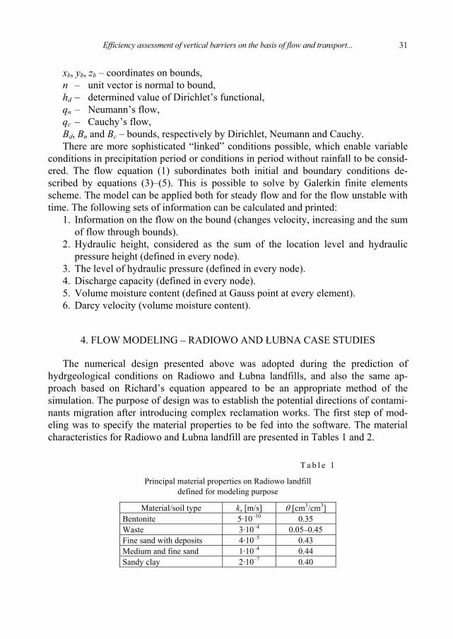
The numerical design presented above was adopted during the prediction ofhydrgeological conditions on Radiowo and Łubna landfills, and also the same ap-proach based on Richard’s equation appeared to be an appropriate method of thesimulation. The purpose of design was to establish the potential directions of contami-nants migration after introducing complex reclamation works. The first step of mod-eling was to specify the material properties to be fed into the software. The materialcharacteristics for Radiowo and Łubna landfill are presented in Tables 1 and 2.
T a b l e 1
Principal material properties on Radiowo landfilldefined for modeling purpose
Material/soil type ks [m/s] θ [cm3/cm3]Bentonite 5·10–10 0.35Waste 3·10–4 0.05–0.45Fine sand with deposits 4·10–5 0.43Medium and fine sand 1·10–4 0.44Sandy clay 2·10–7 0.40
E. KODA et al.32
T a b l e 2
Principal material properties on Łubna landfilldefined for modeling purpose
Material/soil type ks [m/s] θ [cm3/cm3]Bentonite 5·10–10 0.35Waste 3·10–4 0.05–0.45Fine sand with deposits 4·10–5 0.43Medium and fine sand 1·10–4 0.44Sandy clay 2·10–7 0.40
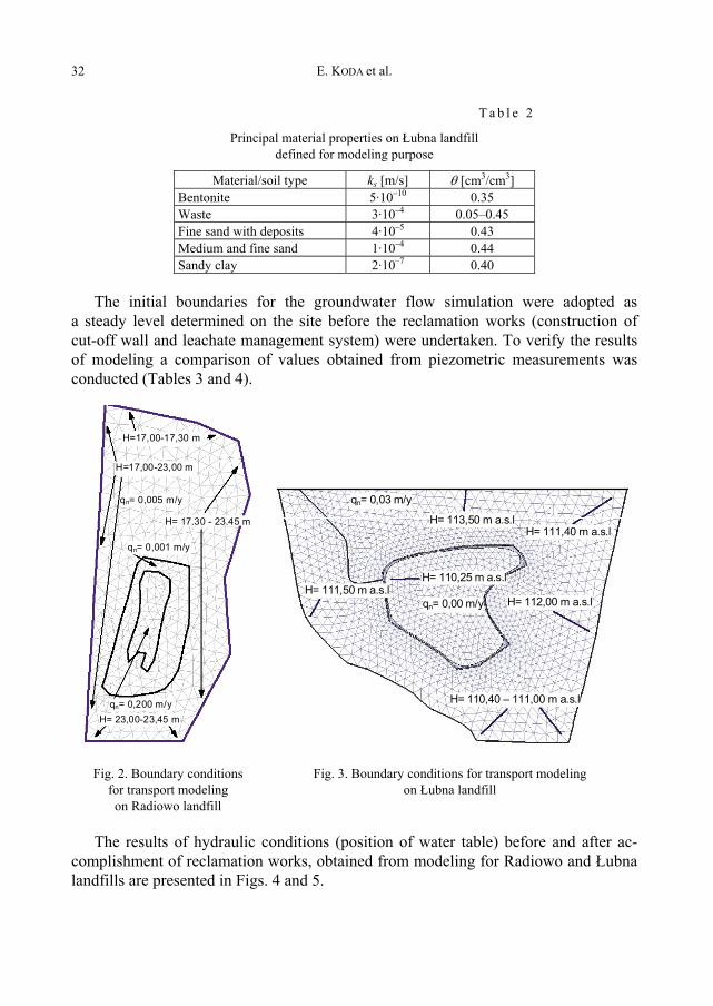
The initial boundaries for the groundwater flow simulation were adopted asa steady level determined on the site before the reclamation works (construction ofcut-off wall and leachate management system) were undertaken. To verify the resultsof modeling a comparison of values obtained from piezometric measurements wasconducted (Tables 3 and 4).
H=17,00-17,30 m
H=17,00-23,00 m
qn= 0,005 m/y
qn= 0,001 m/y
qn= 0,200 m/y H= 23,00-23,45 m
H= 17,30 - 23,45 m
qn= 0,03 m/y
H= 113,50 m a.s.lH= 111,40 m a.s.l
H= 112,00 m a.s.l
H= 110,25 m a.s.lH= 111,50 m a.s.l
H= 110,40 – 111,00 m a.s.l
qn= 0,00 m/y
Fig. 2. Boundary conditionsfor transport modelingon Radiowo landfill
Fig. 3. Boundary conditions for transport modelingon Łubna landfill
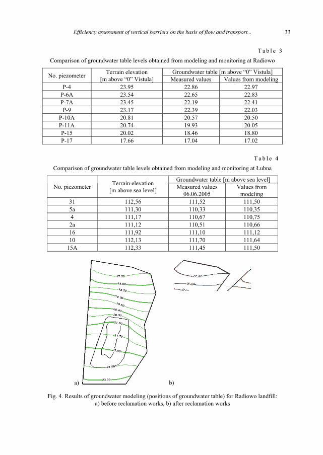
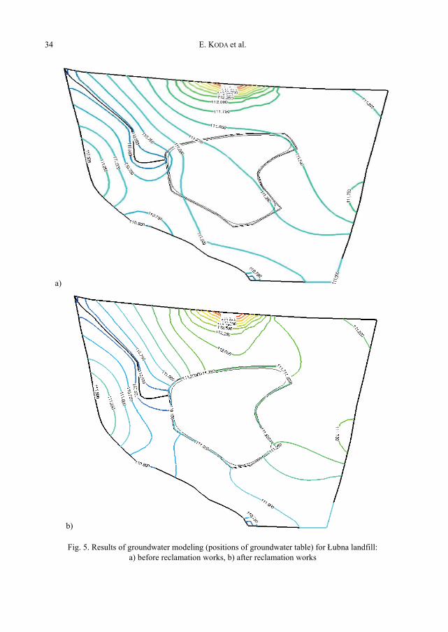
The results of hydraulic conditions (position of water table) before and after ac-complishment of reclamation works, obtained from modeling for Radiowo and Łubnalandfills are presented in Figs. 4 and 5.
Efficiency assessment of vertical barriers on the basis of flow and transport... 33
T a b l e 3Comparison of groundwater table levels obtained from modeling and monitoring at Radiowo
Groundwater table [m above “0” Vistula]No. piezometer Terrain elevation[m above “0” Vistula] Measured values Values from modeling
P-4 23.95 22.86 22.97P-6A 23.54 22.65 22.83P-7A 23.45 22.19 22.41P-9 23.17 22.39 22.03
P-10A 20.81 20.57 20.50P-11A 20.74 19.93 20.05P-15 20.02 18.46 18.80P-17 17.66 17.04 17.02
T a b l e 4Comparison of groundwater table levels obtained from modeling and monitoring at Łubna
Groundwater table [m above sea level]No. piezometer Terrain elevation
[m above sea level] Measured values06.06.2005
Values frommodeling
31 112,56 111,52 111,505a 111,30 110,33 110,354 111,17 110,67 110,752a 111,12 110,51 110,6616 111,92 111,10 111,1210 112,13 111,70 111,64
15A 112,33 111,45 111,50
a) b)
Fig. 4. Results of groundwater modeling (positions of groundwater table) for Radiowo landfill:a) before reclamation works, b) after reclamation works
E. KODA et al.34
a)
b)
Fig. 5. Results of groundwater modeling (positions of groundwater table) for Łubna landfill:a) before reclamation works, b) after reclamation works
Efficiency assessment of vertical barriers on the basis of flow and transport... 35
All the examples given in the article refer to the prediction of groundwater flowand transport changes due to engineering works. In all case studies such works mainlyconsisted of cut-off wall construction [8], [9]. All of them proved that the numericalmodeling could be a comprehensive method of prediction of groundwater flow, how-ever it would be worth assessing physically whether designed models contribute withreal environmental conditions. Additionally such analysis would allow assessing theeffectiveness of cut-off wall construction on landfills [20].
5. ASSESSMENT OF MODELING RELIABILITY AND EFFECTIVENESSOF VERTICAL BARRIER ON LANDFILLS
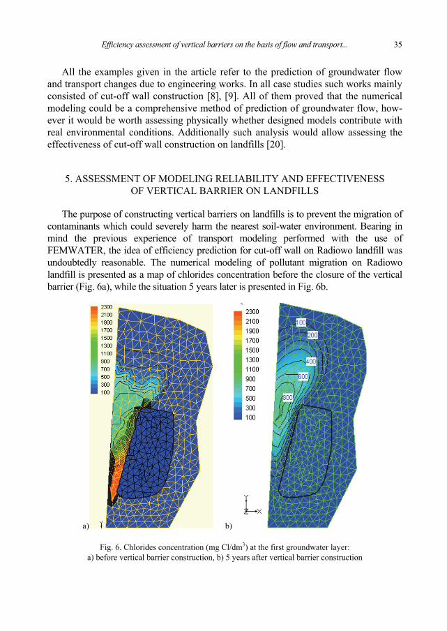
The purpose of constructing vertical barriers on landfills is to prevent the migration ofcontaminants which could severely harm the nearest soil-water environment. Bearing inmind the previous experience of transport modeling performed with the use ofFEMWATER, the idea of efficiency prediction for cut-off wall on Radiowo landfill wasundoubtedly reasonable. The numerical modeling of pollutant migration on Radiowolandfill is presented as a map of chlorides concentration before the closure of the verticalbarrier (Fig. 6a), while the situation 5 years later is presented in Fig. 6b.
a) b)
Fig. 6. Chlorides concentration (mg Cl/dm3) at the first groundwater layer:a) before vertical barrier construction, b) 5 years after vertical barrier construction
E. KODA et al.36
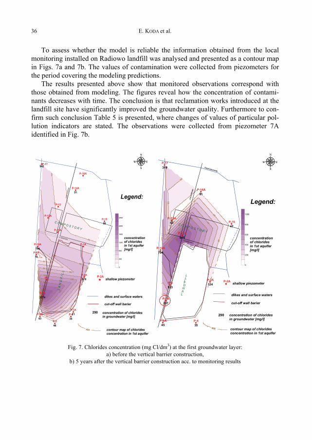
To assess whether the model is reliable the information obtained from the localmonitoring installed on Radiowo landfill was analysed and presented as a contour mapin Figs. 7a and 7b. The values of contamination were collected from piezometers forthe period covering the modeling predictions.
The results presented above show that monitored observations correspond withthose obtained from modeling. The figures reveal how the concentration of contami-nants decreases with time. The conclusion is that reclamation works introduced at thelandfill site have significantly improved the groundwater quality. Furthermore to con-firm such conclusion Table 5 is presented, where changes of values of particular pol-lution indicators are stated. The observations were collected from piezometer 7Aidentified in Fig. 7b.
P-2A
290
400
P-17
P-1A
P-2A
P-3AP-4
P-5
P-6A
P-7A
P-8A
P-9
P-10A
P-11A
P-12A
P-13
P-14A
P-15
P-16A
978
2135
46
63
2374
76
744
51
50
542
L A
N D
F I
L L
C O M P O S T O R Y
Lini
a ko
lejo
wa
ul. Kampinoska
0
400
800
1200
1600
2000
2400
Legend:
concentrationof chloridesin 1st aquifer[mg/l]
contour map of chlorides concentration in 1st aquifer
concentration of chlorides in groundwater [mg/l]
shallow piezometer
dikes and surface waters
cut-off wall barier
P-2A
290
Kanał
Zaborowski
400
P-2A
P-4P-6A
P-7A
P-9
P-10A
P-11A
P-12A
P-14A
P-15
P-17
124
3545
237
533
704
985
63
81
47
319
L A N D F I L L
C O
M
P
O
S
T
O
R
Y
Linia
kolejowa
ul.
Kampinoska
0
200
400
600
800
1000
Legend:
concentration of chlorides in 1st aquifer [mg/l]
contour map of chlorides concentration in 1st aquifer
concentration of chlorides in groundwater [mg/l]
shallow piezometer
dikes and surface waters cut-off wall barier
Fig. 7. Chlorides concentration (mg Cl/dm3) at the first groundwater layer:a) before the vertical barrier construction,
b) 5 years after the vertical barrier construction acc. to monitoring results
Efficiency assessment of vertical barriers on the basis of flow and transport... 37
T a b l e 5
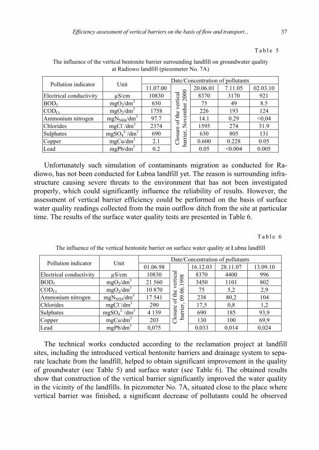
The influence of the vertical bentonite barrier surrounding landfill on groundwater qualityat Radiowo landfill (piezometer No. 7A)
Date/Concentration of pollutantsPollution indicator Unit 11.07.00 20.06.01 7.11.05 02.03.10Electrical conductivity µS/cm 10830 8370 3170 921BOD5 mgO2/dm3 650 75 49 8.5CODCr mgO2/dm3 1758 226 193 124Ammonium nitrogen mgNNH4/dm3 97.7 14.1 0.29 <0,04Chlorides mgCl–/dm3 2374 1595 274 31.9Sulphates mgSO4
2–/dm3 690 630 805 131Copper mgCu/dm3 2.1 0.600 0.228 0.05Lead mgPb/dm3 0.2
Clo
sure
of t
he v
ertic
alba
rrie
r, N
ovem
ber 2
000
0.05 <0.004 0.005
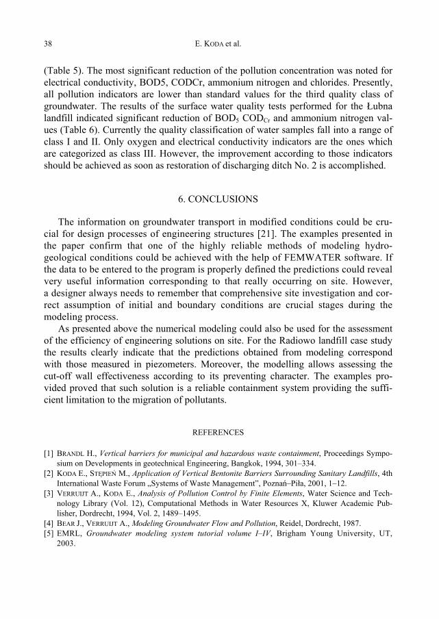
Unfortunately such simulation of contaminants migration as conducted for Ra-diowo, has not been conducted for Łubna landfill yet. The reason is surrounding infra-structure causing severe threats to the environment that has not been investigatedproperly, which could significantly influence the reliability of results. However, theassessment of vertical barrier efficiency could be performed on the basis of surfacewater quality readings collected from the main outflow ditch from the site at particulartime. The results of the surface water quality tests are presented in Table 6.
T a b l e 6
The influence of the vertical bentonite barrier on surface water quality at Łubna landfill
Date/Concentration of pollutantsPollution indicator Unit 01.06.98 16.12.03 28.11.07 13.09.10Electrical conductivity µS/cm 10830 8370 4400 996BOD5 mgO2/dm3 21 560 3450 1101 802CODCr mgO2/dm3 10 870 75 5,2 2,9Ammonium nitrogen mgNNH4/dm3 17 541 238 80,2 104Chlorides mgCl–/dm3 290 17,5 0,8 1,2Sulphates mgSO4
2–/dm3 4 139 690 185 93,9Copper mgCu/dm3 203 130 100 69,9Lead mgPb/dm3 0,075
Clo
sure
of t
he v
ertic
alba
rrie
r, 09
.06.
1998
0,033 0,014 0,024
The technical works conducted according to the reclamation project at landfillsites, including the introduced vertical bentonite barriers and drainage system to sepa-rate leachate from the landfill, helped to obtain significant improvement in the qualityof groundwater (see Table 5) and surface water (see Table 6). The obtained resultsshow that construction of the vertical barrier significantly improved the water qualityin the vicinity of the landfills. In piezometer No. 7A, situated close to the place wherevertical barrier was finished, a significant decrease of pollutants could be observed
E. KODA et al.38
(Table 5). The most significant reduction of the pollution concentration was noted forelectrical conductivity, BOD5, CODCr, ammonium nitrogen and chlorides. Presently,all pollution indicators are lower than standard values for the third quality class ofgroundwater. The results of the surface water quality tests performed for the Łubnalandfill indicated significant reduction of BOD5 CODCr and ammonium nitrogen val-ues (Table 6). Currently the quality classification of water samples fall into a range ofclass I and II. Only oxygen and electrical conductivity indicators are the ones whichare categorized as class III. However, the improvement according to those indicatorsshould be achieved as soon as restoration of discharging ditch No. 2 is accomplished.
6. CONCLUSIONS
The information on groundwater transport in modified conditions could be cru-cial for design processes of engineering structures [21]. The examples presented inthe paper confirm that one of the highly reliable methods of modeling hydro-geological conditions could be achieved with the help of FEMWATER software. Ifthe data to be entered to the program is properly defined the predictions could revealvery useful information corresponding to that really occurring on site. However,a designer always needs to remember that comprehensive site investigation and cor-rect assumption of initial and boundary conditions are crucial stages during themodeling process.
As presented above the numerical modeling could also be used for the assessmentof the efficiency of engineering solutions on site. For the Radiowo landfill case studythe results clearly indicate that the predictions obtained from modeling correspondwith those measured in piezometers. Moreover, the modelling allows assessing thecut-off wall effectiveness according to its preventing character. The examples pro-vided proved that such solution is a reliable containment system providing the suffi-cient limitation to the migration of pollutants.
REFERENCES
[1] BRANDL H., Vertical barriers for municipal and hazardous waste containment, Proceedings Sympo-sium on Developments in geotechnical Engineering, Bangkok, 1994, 301–334.
[2] KODA E., STĘPIEŃ M., Application of Vertical Bentonite Barriers Surrounding Sanitary Landfills, 4thInternational Waste Forum „Systems of Waste Management”, Poznań–Piła, 2001, 1–12.
[3] VERRUIJT A., KODA E., Analysis of Pollution Control by Finite Elements, Water Science and Tech-nology Library (Vol. 12), Computational Methods in Water Resources X, Kluwer Academic Pub-lisher, Dordrecht, 1994, Vol. 2, 1489–1495.
[4] BEAR J., VERRUIJT A., Modeling Groundwater Flow and Pollution, Reidel, Dordrecht, 1987.[5] EMRL, Groundwater modeling system tutorial volume I–IV, Brigham Young University, UT,
2003.
Efficiency assessment of vertical barriers on the basis of flow and transport... 39
[6] LIN H.C., RICHARDS D.R., YEH G.T., CHENG J.R., CHENG H.P., JONEM N.L., FEMWATER: a three-dimensional finite element computer model for simulating density-dependent flow and transport invariably saturated media, Technical Report CHL-97-12, U.S. Army Corps of Engineer, 1997.
[7] JESSBERGER H.L. ed., Geotechnics of Landfill Design and Remedial Works – Technical Recommen-dation GLR, Ernst & Sohn, Berlin, 1993.
[8] KODA E. Groundwater Protection System for Old Landfill Leachate Containment, Proceedings ofthe 12th Danube-European Conference on Geotechnical Engineering, Passau, 567–570.
[9] BATOG A., HAWRYSZ M., Geotechnical problems of raising the capacity of exploited landfill sites,Studia Geotechnica et Mechanica, 2005, Vol. XXVII, No. 1–2, 13–20.
[10] FRATALOCCHI E., PASQUALINI E., Permeability over time of cement-bentonite slurry walls, Proceed-ings of the 3rd International Congress on Environmental Geotechnics, Lisboa, 1998, Vol. 2,509–514.
[11] LIPINSKI M.J., KODA E., WDOWSKA M.K., Assessment of key geotechnical characteristics ofa groundwater protective vertical barrier, Proceedings of the 14th European Conference on SoilMechanics and Geotechnical Engineering, Madrid, 2007, Vol. 2, 767–772.
[12] KODA E., SKUTNIK Z., Quality control tests of vertical bentonite barriers for old sanitary landfillcontainment, Proceedings of the 13th European Conference on Soil Mechanics and GeotechnicalEngineering, Praha, 2003, Vol. 1, 409–414.
[13] SOGA K., JOSHI K., Long-term Performance of cement-bentonite cut-off walls: A case study, Pro-ceedings of the 6th International Congress on Environmental Geotechnics, New Delhi, 2010, Vol. 1,151–164.
[14] Van GENUCHTEN M.T., A closed-form equation for predicting the hydraulic conductivity of unsatu-rated soil, Soil Science Society Journal, 1980, 44, 892–898.
[15] CARSEL R.F., PARRISH R.S., Developing joint probability distribution of soilwater retention charac-teristics, Water Resources Research, 1988, Vol. 24, No. 5, 755–760.
[16] ROWE R.K., QUIGLEY R.M., BROKER J.R., Clayey Barrier Systems for Waste Disposal Facilities,Chapman & Hall, London, 1995.
[17] SHACKELFORD C.D., ROWE R.K., Contaminant Transport Modeling, Proceedings of the 3rd Interna-tional Congress on Environmental Geotechnics, Lisboa, 1998, Vol. 3, 939–956.
[18] KODA E., ŻAKOWICZ S., Physical and hydraulics properties of the MSW for water balance of thelandfill, Proceedings of the 3rd International Congress on Environmental Geotechnics, Lisboa, 1998,Vol. 1, 217–222.
[19] KODA E., Local water monitoring on surroundings of sanitary landfill, Annals of Warsaw AgriculturalUniversity – SGGW, Land Reclamation, 2004, No. 35a, 131–144.
[20] KODA E., Assessment of efficiency of the old landfill protection system based on transport modeling andmonitoring research, Proceedings of the 6th International Congress on Environmental Geotechnics, NewDelhi, 2010, Vol. II, 1623–1630.
[21] KODA E., Stability and pollutant transport from remediated landfills with the use of ObservationalMethod, SGGW, Warsaw, 2011 (in Polish).