Embed Size (px)
Citation preview
ArSPI: An Artifact Model for Software Process Improvement and Management
Authors Marco Kuhrmann Technische Universität München,
Faculty of Informatics, 85748 Garching, Germany
Abstract Software process adaptation and improvement (SPI) addresses the need of companies to adapt new and/or im-prove their software processes in order to meet, e.g. business optimization goals or regulative requirements. Such an initiative comprises manifold activities, e.g. analyzing, designing, realizing, evaluating, and deploying new software processes or, respectively, new versions/variants of a maintained software process. Therefore, such initiatives are often considered to be (self-contained) projects.
Although reference models such as CMMI and ISO 15504 contain practices and assessment methods they, however, lack in defining supporting artifacts for SPI projects, which help process engineers to structure the outcomes, to guide process engineers during the set-up and the operation of SPI projects. Therefore, setting-up and operating SPI projects highly depends on the individual expertise of process engineers. In this report, we present a compact artifact model and a set of complementing processes to support SPI projects and software process management (SPM), which we inferred from six years of experience. The presented model serves as template for creating analysis, design, and supporting artifacts in SPI projects. Furthermore, the artifact model is embedded into an organizational context in which SPI projects are initiated and executed, and the results are deployed to the process consumers.
The report at hands serves as “data sink” and contains all detailed artifact model descriptions and further infor-mation aiding the definition of a software process management approach and, furthermore, provides guidance to process engineers to organize and manage a particular SPI project.
Keywords Software Process Improvement, Software Process Management, SPI, Artifact Model
CR-Classification D.2, D.2.9
Reviewers The report at hands is the result of numerous discussions. It was reviewed and discussed with the following people (in alphabetical order):
• Jens Calamé • Sarah Beecham • Manfred Broy • Georg Kalus • Oliver Linssen • Daniel Mendéz Fernández • Ita Richardson • André Schnackenburg
Thank you very much for your support.
Content
1 Introduction ...................................................................................................................................................... 1 1.1 Context and Project Settings ........................................................................................................................ 1 1.2 Contribution .................................................................................................................................................. 6 1.3 Research Method, Previous Investigations, and Related Contributions. ...................................................... 6 1.4 Outline .......................................................................................................................................................... 7 2 Related Work ................................................................................................................................................... 7 3 Analysis of the SPI-Projects ............................................................................................................................ 9 3.1 Practices ..................................................................................................................................................... 10 3.2 Artifacts ....................................................................................................................................................... 10 3.3 Lessons Learned ........................................................................................................................................ 11 4 SPI & SPM Artifact Model .............................................................................................................................. 12 4.1 Terms & Definitions .................................................................................................................................... 12 4.2 The SPI & SPM Artifact Model – A Bird’s Eyes Perspective ...................................................................... 14 4.3 SPI & SPM Triggers and Success .............................................................................................................. 17 5 Conclusion & Future Work ............................................................................................................................. 20 6 References .................................................................................................................................................... 22 7 SPI & SPM Artifacts ....................................................................................................................................... 26 7.1 Key Artifacts ............................................................................................................................................... 26 7.2 Complementing Artifacts ............................................................................................................................ 37 8 SPI & SPM Processes ................................................................................................................................... 39 8.1 The Process Life Cycle ............................................................................................................................... 39 8.2 The Basic Single-SPI Process .................................................................................................................... 41 8.3 The Extended Software Process Line SPI Process ................................................................................... 45 8.4 Analysis and Design Decisions .................................................................................................................. 52 9 Further Information ........................................................................................................................................ 56 9.1 Artifact Catalog ........................................................................................................................................... 56 9.2 Tailoring the Artifact Model ......................................................................................................................... 58 9.3 Quality Assessment & Checklists ............................................................................................................... 62 9.4 Artifact Representation and Data Formats ................................................................................................. 65 10 Glossary ......................................................................................................................................................... 69 11 The ArSPI Model ........................................................................................................................................... 69 11.1 The Overall Model .................................................................................................................................... 69 11.2 Relation: Conceptual and Technical Process Design ............................................................................... 72 11.3 Relation Process Asstes and Conceptual Process Design ...................................................................... 73 11.4 Relation Process Assets and Technical Process Design ......................................................................... 74

Figures
Figure 1 The V-Modell XT family tree (analysis from January 2013) ..................................................................... 5 Figure 2 SPI model terminology ........................................................................................................................... 14 Figure 3 Overall view on software process improvement (SPI) projects. ............................................................. 15 Figure 4 Overall view on software process management (SPM) and its relation to SPI- and software projects. 16 Figure 5 Process Requirements – artifact structure ............................................................................................. 26 Figure 6 Conceptual Process Design – artifact structure ..................................................................................... 28 Figure 7 Technical Process Design – artifact structure ........................................................................................ 31 Figure 8 Process Life Cycle Support – artifact structure and related artifacts ..................................................... 33 Figure 9 The Process Release – structure and relation to other artifacts ............................................................ 36 Figure 10 Complementing artifacts from quality management ............................................................................ 38 Figure 11 Complementing artifacts from project organization and management ................................................ 39 Figure 12 Software process life cycle in a Singe-SPI project ............................................................................... 40 Figure 13 An exemplary development process instance with three iterations and parallel work ......................... 41 Figure 14 Key activities in the SPLC model for analyzing, designing, realizing, and deploying a process .......... 42 Figure 15 Software process life cycle in a software process line-based SPM ..................................................... 45 Figure 16 Change management process – SPI project perspective. ................................................................... 49 Figure 17 Change management – software process management perspective. ................................................. 49 Figure 18 Release management – Condensed view ........................................................................................... 51

Tables
Table 1 Overview over the projects. ....................................................................................................................... 2 Table 2 Size and complexity of the V-Modell XT variants under consideration. .................................................... 4 Table 3 Overview over the applied research methods. .......................................................................................... 6 Table 4 Most common practices extracted from the projects. .............................................................................. 10 Table 5 General questions and corresponding criteria influencing SPI projects .................................................. 18 Table 6 Overview: standard changes and cases as initially covered by the SPI/SPM model ............................. 19 Table 7 Sub-artifacts composed in the process requirements. ............................................................................ 27 Table 8 Sub-artifacts composed in the conceptual process design. .................................................................... 29 Table 9 Sub-artifacts composed in the technical process design. ....................................................................... 32 Table 10 Sub-artifacts composed in the process life cycle support. .................................................................... 34 Table 11 Phases of the software process life cycle model. ................................................................................. 40 Table 12 Refined activity: Design Organization and Role Model ......................................................................... 42 Table 13 Refined activity: Design Artifact Model .................................................................................................. 43 Table 14 Refined activity: Design Process Model ................................................................................................ 44 Table 15 Refined activity: Design and Implement the Model Organization ......................................................... 44 Table 16 Refined activity: Refine and Implement the Tailoring Model ................................................................. 44 Table 17 Basic tailoring profiles for the artifact model. ........................................................................................ 62 Table 18 Overview over possible key artifact materializations ............................................................................. 65 Table 19 Proposed minimal data structure for roles ............................................................................................ 67 Table 20 Proposed minimal data structure for artifacts ........................................................................................ 67 Table 21 Proposed minimal data structure for activities ...................................................................................... 68


Introduction - Page 1
1 Introduction Although being a topic of interest for many years, software process improvement (SPI) and software process management (SPM) remain challenging tasks, e.g. [14], [19], [28]. Software processes are the glue that holds organizations, projects, and people together. Depending on the context, software processes may comprehend up to thousands of process elements, which need to be designed, implemented, quality assured, and managed. In contrast to lightweight agile methods, comprehensive software processes – as for example used by “global play-ers” – thus have high requirements, e.g. on process engineering frameworks. Therefore, the development, the maintenance, and the improvement of a software process constitute challenging tasks for – at least – two rea-sons: (1) organizational reasons that comprehend methodical and technical aspects, and (2) psychological rea-sons. Especially in the area of technical and methodical support for process engineers, our research results show several gaps, e.g. regarding the maturity of process engineering frameworks in general, or process construction and management methods in particular (cf. Sect. 2).
Besides the research results, our day-to-day business in consulting and executing SPI projects also shows a gap in the methodical support. Process engineers often have to use a “trial & error” approach; a concrete playbook that summarizes the essential tasks and the minimal set of artifacts (including the required structure and con-tents) is not defined by the established standards at all (cf. Sect. 2). To this end, process engineers have to de-velop their own “best of breed” approaches in order to master SPI projects. The difficulty increases if not only a single SPI project is considered, but a comprehensive software process that is part of a (evolving) software pro-cess line (SPL; e.g. [41], [82], [86]). All results that are produced in a SPI project, e.g. process designs, process releases, have to be considered from a different perspective.
In this section…
In this section, we first describe the background of our research in Sect. 1.1. We describe the projects in which we de-veloped and tested our approach. At the end of this section, we present the overall contribution of the report at hands, outline the research methods, and give an outline of the whole report document. For readers, who are not interested in the “preludes” the out come of our research – the artifact model for SPI and SPM – is briefly described in Sect. 4, and described in every detail in Sect. 7 et seq.
1.1 Context and Project Settings Our work is based on a number of SPI projects, which we operated over the years. The majority of these pro-jects were done in the context of the German V-Modell XT1 and, therefore, also the V-Modell XT inspired the presented results. In this section, we give a short overview over these projects and provide some context infor-mation2.
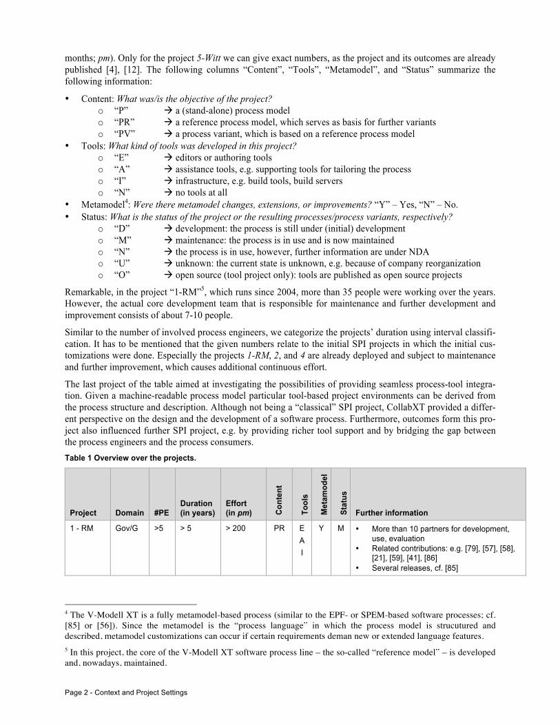
The information of the projects to which we refer is summarized in Table 1. The column “Domain” classifies the project. The classifier “Gov” points to a project, which was operated in the context of a government agency, whereby the postfix “G” indicates a project, which deals with general administration tasks, e.g. procurement, bidding, acquisition, contracting, service provider management, project monitoring, or administration in gen-eral. The postfix “SD” indicates processes that address software development. While the “G” variants still stay on a fairly generic level, the “SD” variants contain concrete artifacts and methods aiding software development teams in software projects. The classifier “Industry” indicates a process that was deployed in a company dealing with software development. In the column “#PE”, we classify the number of process engineers3 participating in the SPI project. In the same way, we give the numbers for the duration (in years) and the effort (in person
1 For detailed information regarding the V-Modell XT, please refer to http://www.v-modell-xt.de (an English version is available). The V-Modell XT is a process-engineering framework in which tools, metamodels, and reference im-plementations build a comprehensive infrastructure to define (software) process models. A short introduction can be found in [85] and [86], in-depth introductions and further information can be depicted from, e.g. [21] (reference process model), [87] (process metamodel), and [59] (technical customization method). 2 For confidentiality reasons, we cannot give detailed information to all of the considered projects. Most of the pro-jects were operated in a government environment and, therefore, underlay strict non-disclosure agreements. 3 For confidentiality reason we cannot give the exact numbers, but provide an interval classification.
Page 2 - Context and Project Settings
months; pm). Only for the project 5-Witt we can give exact numbers, as the project and its outcomes are already published [4], [12]. The following columns “Content”, “Tools”, “Metamodel”, and “Status” summarize the following information:
• Content: What was/is the objective of the project? o “P” à a (stand-alone) process model o “PR” à a reference process model, which serves as basis for further variants o “PV” à a process variant, which is based on a reference process model
• Tools: What kind of tools was developed in this project? o “E” à editors or authoring tools o “A” à assistance tools, e.g. supporting tools for tailoring the process o “I” à infrastructure, e.g. build tools, build servers o “N” à no tools at all
• Metamodel4: Were there metamodel changes, extensions, or improvements? “Y” – Yes, “N” – No. • Status: What is the status of the project or the resulting processes/process variants, respectively?
o “D” à development: the process is still under (initial) development o “M” à maintenance: the process is in use and is now maintained o “N” à the process is in use, however, further information are under NDA o “U” à unknown: the current state is unknown, e.g. because of company reorganization o “O” à open source (tool project only): tools are published as open source projects
Remarkable, in the project “1-RM”5, which runs since 2004, more than 35 people were working over the years. However, the actual core development team that is responsible for maintenance and further development and improvement consists of about 7-10 people.
Similar to the number of involved process engineers, we categorize the projects’ duration using interval classifi-cation. It has to be mentioned that the given numbers relate to the initial SPI projects in which the initial cus-tomizations were done. Especially the projects 1-RM, 2, and 4 are already deployed and subject to maintenance and further improvement, which causes additional continuous effort.
The last project of the table aimed at investigating the possibilities of providing seamless process-tool integra-tion. Given a machine-readable process model particular tool-based project environments can be derived from the process structure and description. Although not being a “classical” SPI project, CollabXT provided a differ-ent perspective on the design and the development of a software process. Furthermore, outcomes form this pro-ject also influenced further SPI project, e.g. by providing richer tool support and by bridging the gap between the process engineers and the process consumers. Table 1 Overview over the projects.
Project Domain #PE Duration (in years)
Effort (in pm) Co
nten
t
Tool
s
Met
amod
el
Stat
us
Further information
1 - RM Gov/G >5 > 5 > 200 PR E A I
Y M • More than 10 partners for development, use, evaluation
• Related contributions: e.g. [79], [57], [58], [21], [59], [41], [86]
• Several releases, cf. [85]
4 The V-Modell XT is a fully metamodel-based process (similar to the EPF- or SPEM-based software processes; cf. [85] or [56]). Since the metamodel is the “process language” in which the process model is strucutured and described, metamodel customizations can occur if certain requirements deman new or extended language features. 5 In this project, the core of the V-Modell XT software process line – the so-called “reference model” – is developed and, nowadays, maintained.

Introduction - Page 3
Project Domain #PE Duration (in years)
Effort (in pm) Co
nten
t
Tool
s
Met
amod
el
Stat
us
Further information
2 Gov/G >5 2 - 4 15 - 25 PV E A
Y N • 3 parties for the development, several government agencies for the evaluation
3 Gov/SD 2 - 4 1 10 - 15 PV I Y N • Mature and experienced organization • Extension of a rich directed process model
with a particular software development ap-proach paying special attention custom-er/constructor interfaces and iterative (ag-ile) software development
4 Gov/SD 2 - 4 2 - 4 10 - 15 PV E A
N N • Mature and experienced organization, however, final customization incl. deploy-ment was achieved in the 3rd approach (reasons: strong opponents, technical evo-lution during the SPI project)
5 - Witt Industry /SD
2 - 4 2 SPI: 20 Witt: 600
P N N U • Development of a process, which uses the reference model and its infrastructure; purpose: software development
• 4 partners incl. the executing company • Related contributions: [4], [12] • Current status: unknown (company reor-
ganization)
6 Gov/G 1 1 5 - 9 P N N D • Development of a process, which uses the reference model and its infrastructure; purpose: general administration and pro-ject management of method and software development projects
• Current status: ongoing, initial release deployed for evaluation
7 - CollabXT
Tool 2 - 4 1 <5 - A - O • Tool development project to enable trans-formation of processes in order to be exe-cuted by several project-supporting tools
• 3 partners • Related contributions: e.g. [42], [46], [47],
[48], [50]
8 Gov/SD 2-4 1 5 - 9 PV N N U • Development of new sub process dealing with data model development.
• Current status: project was stopped for organizational issues of the client (re-prioritization); project was re-opened 2 years later; current state: unknown
All projects from Table 1 (except CollabXT) resulted in software processes or software process lines of consid-erable size. A couple of thousands of process assets (for the terminology, see Sect. 4.1.2) had to be designed, realized, and maintained over the years.
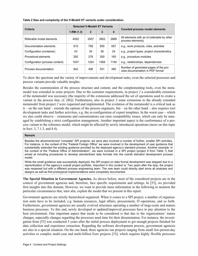
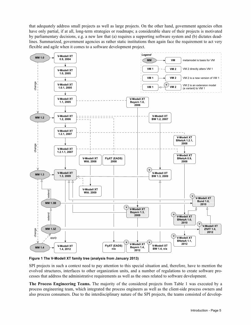
To provide some (technical) insights, Table 2 shows the numbers of the process assets of 4 selected software process variants. The variants refer to the projects from Table 1 in which they were initially developed. Also, variant 2 is a child of the reference model (1-RM), the variants 3 and 4 are children of variant 2. In consequence, the processes mentioned in Table 2 create a variant tree or – more intuitive – a family tree. The whole V-Modell XT family is analyzed in our technical report [85]. To underline the importance of a structured and effi-cient approach to manage such large-scale software processes/software process lines, Figure 1 shows the family tree and the relationships between the single variants and their respective evolution over the years.
Page 4 - Context and Project Settings
Table 2 Size and complexity of the V-Modell XT variants under consideration.
Criteria Selected V-Modell XT Variants
Counted process model elements 1-RM (1.3) 2 3 4
Referable model elements 4002 3507 3902 2889 All elements with an id (referable by other process elements)
Documentation elements 915 758 855 657 e.g., work products, roles, activities
Configuration (container) 43 34 36 24 e.g., project types, project characteristics
Procedural elements 292 278 300 165 e.g., procedure modules
Configuration (process content) 1637 1324 1469 1140 e.g., relationships, dependencies
Process documentation 842 498 551 480 Number of generated pages of the pro-cess documentation in PDF format
To show the spectrum and the variety of improvements and development tasks, even the selected processes and process variants provide valuable insights.
Besides the customization of the process structure and content, and the complementing tools, even the meta-model was extended in some projects. Due to the customer requirements, in project 2 a considerable extension of the metamodel was necessary (the majority of the extensions addressed the set of operations used to create a variant in the process line; cf. [86]). Furthermore, also in project 3 some extensions to the already extended metamodel from project 2 were requested and implemented. The evolution of the metamodel is a critical task as it – on the one hand – extends the options of the process engineers, but – on the other hand – also requires tool development tasks and further activities, e.g. the re-configuration of export templates. In the worst case – which we also could observe – extensions and customizations can raise compatibility issues, which can only be man-aged by establishing a strict configuration management. Another important aspect is the conformance of a pro-cess variant to the reference model, which might be affected by newly introduced operations (more on this topic in Sect. 3, 7.1.3, and 8.4).
Remark
Besides the aforementioned “complete” SPI projects, we were also involved a number of further, smaller SPI activities. For instance, in the context of the “Federal Foreign Office” we were involved in the development of user guidance that substantially extended the existing guidance provided by the deployed agency’s standard process. Another example: In the context of the “Federal Office of Administration”, we were involved in a SPI project (project 8 from Table 1) that aimed at including procedures to develop standardized data formats into the overall standard development process model. While the small guidance was successfully deployed, the SPI project on data format development was stopped due to a reprioritization of the agency’s overall project portfolio. Important in this context is: Two years after the stop, the project was reopened but with a different process engineering team. The new team could directly start since all analyses and designs as well as first prototypical implementations were completely documented.
The Special Situation in Government Agencies. As shown before, most of the considered projects are in the context of government agencies and, therefore, face specific requirements and settings. In [53], we provided first insights into this domain. However, we want to provide more information in the following to mention the particular circumstances that, inter alia, explain the model that we present in this report.
Government agencies are strictly hierarchical organized. When it comes to a SPI project, a number of organiza-tion units have to be included, e.g. human resources, legal affairs, procurement, IT-operations, and so forth. Furthermore, government agencies are usually evolved structures operating a number of large-scale and mature business processes. To this end, newly developed or updated/improved processes have to pay attention to the host environment. One important aspect that needs to be considered is that due to the organizations’ nature changes, especially changes regarding the processes need time for their dissemination. For instance, the investi-gation from [53] was conducted 5 years after the initial process deployment to get enough projects finished for data collection and experience extraction. Regarding the software development process, government agencies are also in a special situation. On the one hand, these agencies run projects ranging from small few-person-day activities to complex multi-year and multi-billion Euro projects [53], which requires highly flexible processes
Introduction - Page 5
that adequately address small projects as well as large projects. On the other hand, government agencies often have only partial, if at all, long-term strategies or roadmaps; a considerable share of their projects is motivated by parliamentary decisions, e.g. a new law that (a) requires a supporting software system and (b) dictates dead-lines. Summarized, government agencies as rather static institutions then again face the requirement to act very flexible and agile when it comes to a software development project.
Figure 1 The V-Modell XT family tree (analysis from January 2013)
SPI projects in such a context need to pay attention to this special situation and, therefore, have to mention the evolved structures, interfaces to other organization units, and a number of regulations to create software pro-cesses that address the administrative requirements as well as the ones related to software development.
The Process Engineering Teams. The majority of the considered projects from Table 1 was executed by a process engineering team, which integrated the process engineers as well as the client-side process owners and also process consumers. Due to the interdisciplinary nature of the SPI projects, the teams consisted of develop-
MM 1.0
V-Modell XT 1.0, 2005
V-Modell XT 0.9, 2004
V-Modell XT 1.0.1, 2005
V-Modell XT 1.1, 2005
V-Modell XT 1.2, 2006
V-Modell XT 1.2.1, 2007
V-Modell XT 1.2.1.1, 2007
MM 1.2 V-Modell XT BW 1.2, 2007
V-Modell XT BNetzA 1.2.1,
2008
V-Modell XT Witt. 2008
FlyXT (EADS) 2008
V-Modell XT 1.3, 2009MM 1.3
V-Modell XT Witt. 2009
V-Modell XT BNetzA 0.9,
2008
V-Modell XT 1.4, 2012MM 1.4
V-Modell XT Bayern 1.0,
2006
V-Modell XT BW 1.3, 2009
V-Modell XT Bund 1.0,
2010
V-Modell XT BNetzA 1.0,
2010V-Modell XT
ZIVIT 1.0, 2012
V-Modell XT BNetzA 1.1,
2012V-Modell XT Bayern 1.4,
2012
FlyXT (EADS) n/a
MM 1.3B
MM 1.3Z
v
v
v
v
v
apply
chan
gech
ange
exte
ndex
tend
chan
ge
MM VM
VM 2VM 1
VM 2VM 1
VM 2VM 1v
metamodel is basis for VM
VM 2 directly alters VM 1
VM 2 is a new version of VM 1
VM 2 is an extension model(a variant) to VM 1
Legend
V-Modell XT Bayern 1.3,
2009
v
vV-Modell XT BW 1.4, n/a
v
Page 6 - Contribution
ers of the process platform, requirements management and project management experts, process management experts and process owners, and supporting personnel. Each team member had a special area of responsibility, e.g. process analysis, process architecture, process implementation, or platform development. For the compre-hensive SPI projects 1-5, the specialization was a necessity, as certain tasks need to be done and aligned to cre-ate a complete process release.
Remark
Notably, similar to a software development project a SPI project bears risks; and communication issues in the process engineering team cause most of them. For example, in one of the projects, the lead process engineer temporarily left the team whereby a handover was not completed. In consequence, some former decisions were not reproducible anymore and actually agreed work packages were re-opened. Summarized, a SPI project requires a competent process engineering team. If a single process engineer drives a SPI project, inner-team communication is not that important, however, the entire communication to the stakeholders has to be ensured, and no required task in the SPI project should be left out. Single process engineers as well as a whole team therefore need a playbook to succeed in a SPI project.
1.2 Contribution Over the years, we were involved in a number of SPI projects ranging from smaller, evolutionary projects aim-ing at improving selected methods to large-scale SPL-based software processes. We often experienced the lack of concrete guidance and support. To this end, we had to – on the one hand – to extract relevant information from the current scientific literature, practitioner’s experiences and standards, and – on the other hand – learn from our experiences. Over the years, we developed and refined different techniques and approaches that – stepwise – provided us the required support.
In the report at hands, we summarize our experiences and present a generalized, technology-independent model that contains artifacts and complementing processes necessary to organize and manage SPI projects. Further-more, we show the hot spots on which the interfaces to the host organization are defined in order to lay the foundation for an organization-wide software process management (SPM). The presented model lays the foun-dation for further research, especially to extend standard assessment and maturity models such as CMMI by an experience-based and proven artifact model that describes standardized outcomes of SPI projects.
1.3 Research Method, Previous Investigations, and Related Contributions. The model that we present in the following is based on our experiences that also resulted in some contributions. In this section, we briefly describe the research methods applied, and we list the previously published material.
Regarding the reference model (Table 1), we conducted a field study [53] to investigate the feasibility of the reference model. The outcomes were, inter alia, used to aid the development of a V-Modell XT variant specific for the public administration. In this particular endeavor, information and lessons learned from an industrial project were also included [4], [12]. Furthermore, smaller projects that aimed at tool development, e.g. [46], [50], also contributed to a first V-Modell-XT-specific development and improvement method [27], [45], [44], and [59], which was inspired by process line development, e.g. [41], [82] and [86], but described on a fairly technical level. Over the years, we refined and generalized the proposed method, and applied it in the projects 3, 4 and 8 from Table 1. Already during this particular application, we refined the generalized approach and tested the improvements with student groups [54], [55]. As the outcomes proved appropriate we tailored and applied the approach again in project 6 from Table 1. In order to get sound results, we applied the following research methods (brief overview): Table 3 Overview over the applied research methods.
Method Description
Surveys and interviews
In order to get project experiences and concrete requirements to be mentioned in the further de-velopment of software process in general and the reference model in particular, we conducted a field study in which project managers and process owners were asked to fill out a questionnaire. The field study generated about 30 data points for further evaluation [53]. Furthermore, several literature reviews were conducted to get in-depth information for selected aspects used to back up our results when drawing the conclusions.
Related Work - Page 7
Method Description
Data repository analyses
For all projects in which we were involved, we investigated the repositories that were used to store the project data related to management and development. The resulting information was used to extract key artifacts and information assets to be considered for future SPI projects. The results significantly contribute to the report at hands.
Experiments Developed methods and tools were also tested in a controlled environment using students as subjects. Since concrete guidelines for conducting SPI-related experiments in such environments (duration, qualification, size of the process, etc.) is not available, we did not only conduct first experiments, but also developed a respective guideline [54], [55].
Monitored projects For two of the projects from Table 1, we not only took part in the process design and develop-ment, but also explicitly monitored the projects. Project 5 is already finished and provided us with a number of insights that were used, e.g. to develop the fist notion of a systematic software pro-cess design and development [44] and [59]. Experiences from this particular were reported in [12] and [4]. Project 6 from Table 1 is the latest project in which we currently apply the developed SPI approach.
Tool development and evaluation
In addition to the project work and the (empirical) investigations, the development of tools and their application and evaluation significantly contributed to our work. The developed tools address several phases of the software process life cycle (cf. Sect. 8.1), e.g. the design and authoring support, e.g. [49], [43], [51], [52], or [15], and process enactment, e.g. [42], [48], [50] or [51].
1.4 Outline The report at hands consists of two parts: In Sect. 2, we present and discuss the related work. In Sect. 3, we analyze the projects from Sect. 1.1 for commonalities, e.g. artifacts that were created in all/in the majority of the projects, practices, and experiences. Section 4 presents the derived artifact model for SPI and SPM. The termi-nology is introduced, and the artifact model is presented from the SPI perspective (Sect. 4.2.1) and from the SPM perspective (Sect. 4.2.2). Finally, in Sect. 4.3 we discuss triggers that cause SPI projects and programs and initiate the discussion about the determination of successful SPI/SPM. The first part is concluded in Sect. 5.
The second part of this report contains detailed information and models: In Sect. 7, we present the detailed in-formation and models of the artifact model. Each artifact is presented and defined in detail and, furthermore, the dependencies between the artifacts are described. In Sect. 8, we present the complementing processes required to steer SPI and SPM. In Sect. 8.1, we present the basic software process life cycle, which builds the basis for our SPI/SPM approach. Section 8.2 contains the description of a single-SPI project, and refines artifact struc-tures and processes relevant in the artifacts’ creation. In Sect. 8.3, we extend the process description to a general SPM-based approach in which we consider SPI programs going beyond single-process adaptation and im-provement. Furthermore, we discuss the required management processes and their connection to the SPI-program-hosting organization. Finally, in Sect. 8.4 we present a collection of basic analysis and design deci-sions, which occurred in the projects (Sect. 1.1), and discuss their implications on the proposed artifact model. In the last section 9, we provide further information regarding a catalog that lists all artifacts from the model, tailoring options for the artifact model, and checklists for planning and assessing the application of the artifact model. Finally, we discuss the options to represent the artifacts and give some recommendations regarding the structuring of the artifacts during analysis processes.
2 Related Work Software process improvement is considered of high importance for industry and, therefore, is a frequently researched topic. In this section, we present and discuss work related to our approach going beyond the omni-present maturity models ISO15504 or CMMI and, thereby, structure the publication flora into comparable ap-proaches, general aspects, human factors and success factors, and supporting tools and concrete methods.
Comparable Approaches. Horvat et al. [32] present the PROCESSUS model, which aims at supporting SPI in small and medium companies. They introduce a life cycle model, a set of 17 standard procedures, and a set of 34 standard documents. PROCESSUS itself is based on a synthesis of ISO 9000 and SW-CMM, and refers to the disciplines process automation, process management, supporting activities, software engineering, project management, customer relationship, and introduction/deployment. All these disciplines contain certain process-es, which run through a life cycle that contains analysis, definition, training, enactment, and tracing. Wang et al.
Page 8 - Outline
[91] introduce a unified framework in which SPI is considered in the context of standardized processes. The proposed model provides a terminology and also provides a formal system model for software developing or-ganizations (SDO), which is used to station SPI development processes, SPI management processes, and inter-faces between process defining authorities and process consumption. Nevertheless, Wang et al. [91] only pro-vide terminology and a set of high-level definitions that aid the creation of a consistent terminology, but they do not deliver detailed information about the implementation of SPI in practice. Similar, Joh and Mosly [35] report experiences from a SPI endeavor at Westinghouse ESG. They do not provide detailed information about the concrete implementation of the SPI project, but they show the organizational environment, i.e. the stakeholder groups and their respective top-level activities. Kaltio and Kinnula [38] give a very critical discussion on SPI projects. In their contribution, they complain the usual focus success factors and evaluation, and discus process deployment to be an essential but often under-represented part of SPI initiatives. They report experiences from a practical initiative done with Nokia and conclude that (1) the management of a process (and process parts/assets) is important, (2) that software processes should be considered as “real” products, and (3) similar to products marketing and dissemination is important. Especially Armbrust et al. [4] support last statement: They report on experiences during the deployment of a comprehensive software process into a company. The project to which they refer is also a basis on which our proposed model is built (cf. project 5, Table 1). The perspective, which is taken by Armbrust et al. [4] for the discussion is focused on the organization that owns the process and on the people that are the process consumers. McLoughlin [65] takes the same perspective, and presents a SPI method that is an organization-focused approach aiming at putting more emphasis on business goals and objec-tives. McLoughlin also presents mappings to standard SPI approaches such as CMMI.
Software Process Improvement in General. Concrete, experience- or evidence-based advice on SPI projects can hardly be found. The majority of SPI-related literature can be categorized into literature surveys on SPI in general, or concrete case studies that report on one particular setting, possibly containing a before-after compar-ison. Literature surveys are either on general questions, e.g. [84], [68], [78], [26], or on specific aspects, e.g. human factors [6], [3], [90]. Experience reports, e.g. [88], [34], [81], [16], [25], [17], [18] report on concrete SPI projects. Literature reviews are empirical means to provide grounded knowledge, however, most of the studies focus on general questions (e.g. human aspects and collecting success factors) and do not provide con-crete advice for initiating and operating a SPI project. Due to the various settings and contexts of SPI projects, even the case studies and experience reports are hard to apply. For each setting, a different project setup is re-quired, which also requires a clear understanding of how SPI projects work in general and what the SPI team should do in response to the actual situation. Only Birk and Pfahl [9] demand an organization of SPI projects in the same way software projects are organized. Another perspective is given by Aaen [1] who basically votes against “formal” SPI programs, and to establish an “end-user SPI” instead.
Human Factors and Success Factors. A considerable number of contributions on SPI focus on human factors and success factors (e.g. terminology [20], training [4]). Taking into account that software processes are a “playbook”, which organizes the collaboration of organizations in general and project teams in particular when developing software solutions, human factors have also be considered important. However, the critical – and may be cynical – question, how does this help a process engineering team to initiate, manage, and implement a (new) software process remains unanswered. For example, Stelzer and Mellis [84] provide a list of success fac-tors and conducted a corresponding study to investigate the importance of the found success factors. They con-clude the study that the outcomes show factors that should be considered when starting SPI initiatives. Howev-er, they do not provide concrete advice how to make use of the findings, e.g. by relating the findings to particu-lar improvement steps. Bin Basri et al. [8] show the management or organizational commitment as an important success factor, even for SPI initiatives in small and medium companies. Berander and Wohlin [6] analyzed success factors and, going beyond the majority of comparable investigations, could show that base-lining and synchronizing software processes have to be considered. These findings do not point to general success factors, but to management-related ones that directly address process development and deployment strategies as also mentioned in Armbrust et al. [4] Process users need to know, which process release is the actual one and when will the next release come – summarized: how stable or reliable the actual process is. Allison [3] provides com-parable findings by analyzing several medium-sized teams to investigate the outcomes of a SPI project in rela-tion to the context of the respective teams. Conte et al. [90] conducted a study in which they investigated the human factors learning process, training, motivation, job satisfaction, personality, leadership effectiveness,

Analysis of the SPI-Projects - Page 9
making individual decisions, work stress and perception to be of importance when starting SPI initiatives. Such human factors can influence the SPI program, since participants may have concerns, prejudices, or fears. There-fore, process engineers need to know about such circumstances in order to involve the stakeholders appropriate-ly. Umarji and Seaman [89], Green et al. [24] and Riemenschneider et al. [80] focus on the acceptance of SPI programs in general. Umarji and Seaman discuss acceptance from a psychological point of view and propose a metric-based approach to predict the consequences of SPI-related decisions. Riemenschneider et al. conducted a comprehensive study in which they investigated strategies and methods for project managers to overcome de-veloper resistance.
Tools and Supporting Methods. Besides the general questions and those related to human aspects and success factors, a number of contributions proposing specific solutions or aiming at improving particular processes can be found. For instance, [22], [23] propose a tool support for SPI in small and medium companies. In their ap-proach, the dashboard metaphor, as known from software process control centers (SPCC), is transferred to SPI. Their contribution shows support for the top management, for project management as well as for assessors. However, their contribution remains proprietary, as standard process frameworks such as EPF do not support such features [56], [85]. The majority of tools are proposed for supporting specific phases of a software process life cycle, e.g. enactment (e.g., [46], [47], [48], [50], [51], or [42]) or process modeling (e.g., [49], [51], [52], or [43]).
Supporting tools implement activities that support certain steps in SPI projects. Besides the concrete technical implementations, e.g. [5], a number of conceptual methods that are not fully implemented in tools are proposed in literature. In the following, we present a selection of methods aiming at particular SPI activities. Keto et al. [40] proposes a method that aims at improving the requirements elicitation in SPI projects to avoid misunder-standings and contradictions that might result in conflicts. Lavallée et al. [60] state that most SPI approaches focus on improving the processes while ignoring the impacts on product quality. To this end, an approach is proposed that also pays attention to architectures and product quality in the context of ISO 9126. Malheiros et al. [62] propose a method that demands a broader perspective. They discuss SPI in the context of standard pro-cesses that underlay an evolution in a continuous improvement process at the organizational level. Nevertheless, the majority of contributions proposing concrete methods are focused on assessments, e.g. [61], [11], [67], [13] or [83].
Discussion. Horvat et al. [32] provide a model that is comparable to the approach proposed in the paper at hands. Of special importance are particular disciplines, e.g. project management and the supporting activities. However although PROCESSUS aims at small and medium companies, the approach defines more than 30 artifacts that are named, but not defined in terms of being represented as a self-contained artifact model that provides explanation why certain artifacts have to be created. Furthermore, it is not mentioned how PROCES-SUS can be tailored in order to address SPI projects with different scopes, e.g. the fusion of artifacts to reduce the documentation effort for small SPI endeavors. While the bare number of artifacts being created in a SPI project is, more or less, a matter of the project’s structure and its operation, the harmonization with the hosting environment is left out of scope. Here, Wang et al. [91], Joh and Mosly [35] and Kaltio and Kinnula [38] name and show the importance of bringing the involved stakeholder groups together. However, Wang et al. and Joh and Mosly provide only superficial descriptions on how to do that, while Kaltio and Kinnula and Armbrust et al. [4] show concrete examples for an involvement. Such an involvement is important, as several studies show, e.g. Berander and Wohlin [6], Umarji and Seaman [89] and Riemenschneider et al. [80]. One aspect that is sporadi-cally mentioned is the tool support. However, process-supporting tools that also address process management are rare. While there exists a plethora of editors and some mature process frameworks [56], tools explicitly aiming at supporting the whole process or process line life cycle can barely found and, if at all, have a limited scope, i.e. [22], [23] (management) or [50] (enactment).
3 Analysis of the SPI-Projects For inferring the SPI model, we analyzed the SPI projects from Table 1 (cf. Sect. 1.3). The analyses aimed at the organization and operation aspects to answer the following questions:
• Which steps were done in each project? • Which artifacts were produced each time?
Page 10 - Practices
Based on the analysis, we derived a set of key artifacts that we consider important for SPI projects. Further-more, we could derive a set of techniques and practices that were successfully applied, and which contributed to the construction of the ArSPI model. In order to draw a complete picture, we also list such techniques and prac-tices that did not work properly.
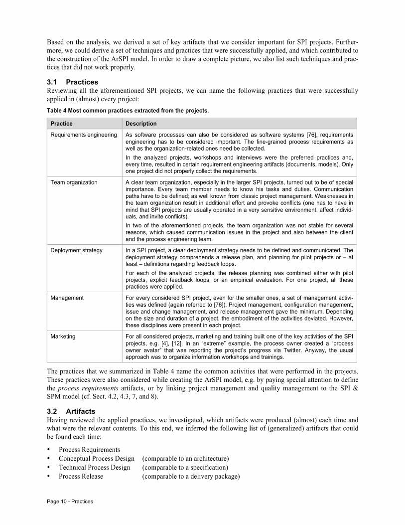
3.1 Practices Reviewing all the aforementioned SPI projects, we can name the following practices that were successfully applied in (almost) every project: Table 4 Most common practices extracted from the projects.
Practice Description
Requirements engineering As software processes can also be considered as software systems [76], requirements engineering has to be considered important. The fine-grained process requirements as well as the organization-related ones need be collected. In the analyzed projects, workshops and interviews were the preferred practices and, every time, resulted in certain requirement engineering artifacts (documents, models). Only one project did not properly collect the requirements.
Team organization A clear team organization, especially in the larger SPI projects, turned out to be of special importance. Every team member needs to know his tasks and duties. Communication paths have to be defined; as well known from classic project management. Weaknesses in the team organization result in additional effort and provoke conflicts (one has to have in mind that SPI projects are usually operated in a very sensitive environment, affect individ-uals, and invite conflicts). In two of the aforementioned projects, the team organization was not stable for several reasons, which caused communication issues in the project and also between the client and the process engineering team.
Deployment strategy In a SPI project, a clear deployment strategy needs to be defined and communicated. The deployment strategy comprehends a release plan, and planning for pilot projects or – at least – definitions regarding feedback loops. For each of the analyzed projects, the release planning was combined either with pilot projects, explicit feedback loops, or an empirical evaluation. For one project, all these practices were applied.
Management For every considered SPI project, even for the smaller ones, a set of management activi-ties was defined (again referred to [76]). Project management, configuration management, issue and change management, and release management gave the minimum. Depending on the size and duration of a project, the embodiment of the activities deviated. However, these disciplines were present in each project.
Marketing For all considered projects, marketing and training built one of the key activities of the SPI projects, e.g. [4], [12]. In an “extreme” example, the process owner created a “process owner avatar” that was reporting the project’s progress via Twitter. Anyway, the usual approach was to organize information workshops and trainings.
The practices that we summarized in Table 4 name the common activities that were performed in the projects. These practices were also considered while creating the ArSPI model, e.g. by paying special attention to define the process requirements artifacts, or by linking project management and quality management to the SPI & SPM model (cf. Sect. 4.2, 4.3, 7, and 8).
3.2 Artifacts Having reviewed the applied practices, we investigated, which artifacts were produced (almost) each time and what were the relevant contents. To this end, we inferred the following list of (generalized) artifacts that could be found each time:
• Process Requirements • Conceptual Process Design (comparable to an architecture) • Technical Process Design (comparable to a specification) • Process Release (comparable to a delivery package)
Analysis of the SPI-Projects - Page 11
• Process Life Cycle Support
The list presents an abstraction of artifacts that were produced in every project – sometimes in different shapes, but with comparable content. Starting with project 2 from Table 1, we put more emphasis on the artifacts and started to develop a generalized artifact model, which we improved over time. The artifact model was tested in a student lab [55] and [54], and the “final” model was also tailored and applied in the project 3, 4 and 6. The arti-fact model is introduced in Sect. 4.
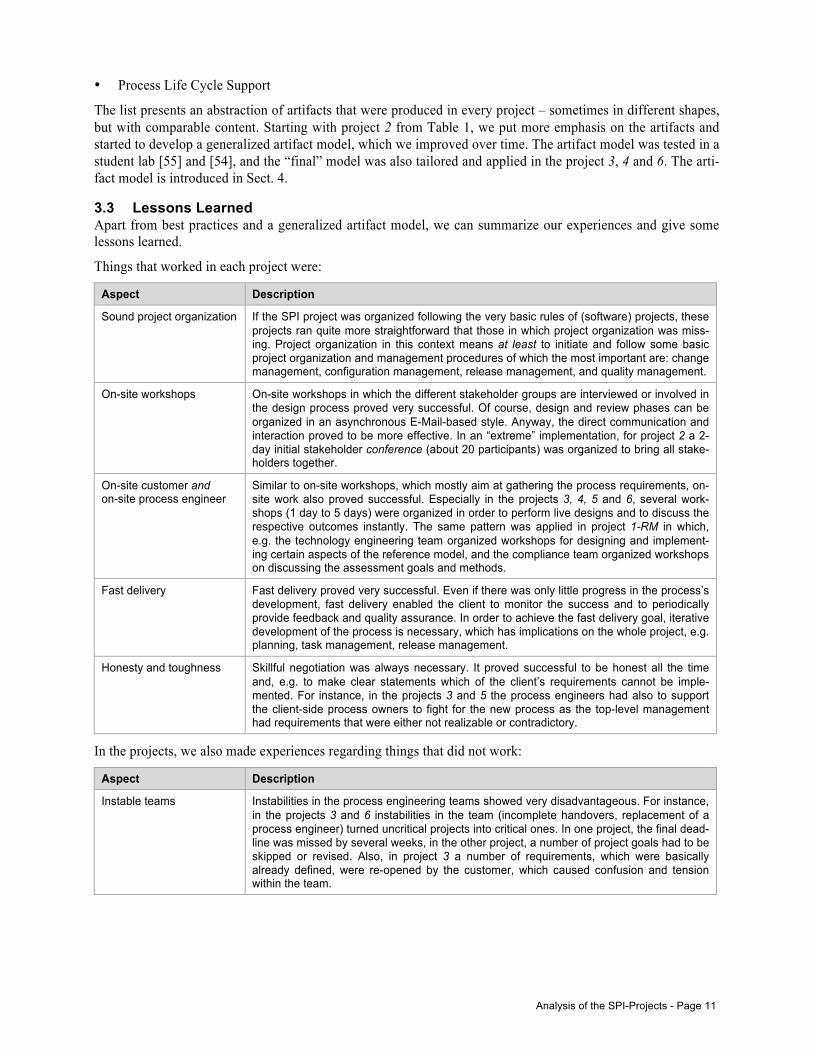
3.3 Lessons Learned Apart from best practices and a generalized artifact model, we can summarize our experiences and give some lessons learned.
Things that worked in each project were:
Aspect Description
Sound project organization If the SPI project was organized following the very basic rules of (software) projects, these projects ran quite more straightforward that those in which project organization was miss-ing. Project organization in this context means at least to initiate and follow some basic project organization and management procedures of which the most important are: change management, configuration management, release management, and quality management.
On-site workshops On-site workshops in which the different stakeholder groups are interviewed or involved in the design process proved very successful. Of course, design and review phases can be organized in an asynchronous E-Mail-based style. Anyway, the direct communication and interaction proved to be more effective. In an “extreme” implementation, for project 2 a 2-day initial stakeholder conference (about 20 participants) was organized to bring all stake-holders together.
On-site customer and on-site process engineer
Similar to on-site workshops, which mostly aim at gathering the process requirements, on-site work also proved successful. Especially in the projects 3, 4, 5 and 6, several work-shops (1 day to 5 days) were organized in order to perform live designs and to discuss the respective outcomes instantly. The same pattern was applied in project 1-RM in which, e.g. the technology engineering team organized workshops for designing and implement-ing certain aspects of the reference model, and the compliance team organized workshops on discussing the assessment goals and methods.
Fast delivery Fast delivery proved very successful. Even if there was only little progress in the process’s development, fast delivery enabled the client to monitor the success and to periodically provide feedback and quality assurance. In order to achieve the fast delivery goal, iterative development of the process is necessary, which has implications on the whole project, e.g. planning, task management, release management.
Honesty and toughness Skillful negotiation was always necessary. It proved successful to be honest all the time and, e.g. to make clear statements which of the client’s requirements cannot be imple-mented. For instance, in the projects 3 and 5 the process engineers had also to support the client-side process owners to fight for the new process as the top-level management had requirements that were either not realizable or contradictory.
In the projects, we also made experiences regarding things that did not work:
Aspect Description
Instable teams Instabilities in the process engineering teams showed very disadvantageous. For instance, in the projects 3 and 6 instabilities in the team (incomplete handovers, replacement of a process engineer) turned uncritical projects into critical ones. In one project, the final dead-line was missed by several weeks, in the other project, a number of project goals had to be skipped or revised. Also, in project 3 a number of requirements, which were basically already defined, were re-opened by the customer, which caused confusion and tension within the team.
Page 12 - Terms & Definitions
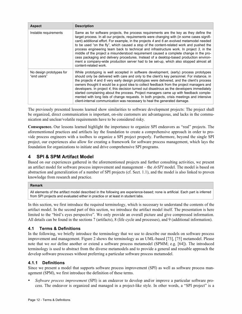
Aspect Description
Instable requirements Same as for software projects, the process requirements are the key as they define the target process. In all our projects, requirements were changing with (in some cases signifi-cant) additional effort. For example, in the projects 4 and 6 an evolved metamodel needed to be used “on the fly”, which caused a stop of the content-related work and pushed the process engineering team back to technical and infrastructure work. In project 3, in the middle of the project a misunderstood requirement caused a complete change in the pro-cess packaging and delivery procedures. Instead of a desktop-based production environ-ment a company-wide production server had to be set-up, which also stopped almost all content-related work.
No design prototypes for “end users”
While prototyping is well accepted in software development, (early) process prototypes should only be delivered with care and only to the client’s key personnel. For instance, in the projects 4 and 6 very early design prototypes were delivered, and the client’s process owners thought it would be a good idea to collect feedback from the project managers and developers. In project 4, this decision turned out disastrous as the developers immediately started complaining about the process. Project managers came up with feedback comple-mented with long lists of change requests. In both projects, crisis meetings and intensive client-internal communication was necessary to heal the generated damage.
The previously presented lessons learned show similarities to software development projects: The project shall be organized, direct communication is important, on-site customers are advantageous, and lacks in the commu-nication and unclear/volatile requirements have to be considered risky.
Consequence. Our lessons learned highlight the importance to organize SPI endeavors as “real” projects. The aforementioned practices and artifacts lay the foundation to create a comprehensive approach in order to pro-vide process engineers with a toolbox to organize a SPI project properly. Furthermore, beyond the single SPI project, our experiences also allow for creating a framework for software process management, which lays the foundation for organizations to initiate and drive comprehensive SPI programs.
4 SPI & SPM Artifact Model Based on our experiences gathered in the aforementioned projects and further consulting activities, we present an artifact model for software process improvement and management – the ArSPI model. The model is based on abstraction and generalization of a number of SPI projects (cf. Sect. 1.1), and the model is also linked to proven knowledge from research and practice.
Remark
All elements of the artifact model described in the following are experience-based; none is artificial. Each part is inferred from SPI projects and evaluated either in practice or at least in student labs.
In this section, we first introduce the required terminology, which is necessary to understand the contents of the artifact model. In the second part of this section, we introduce the artifact model itself. The presentation is here limited to the “bird’s eyes perspective”. We only provide an overall picture and give compressed information. All details can be found in the sections 7 (artifacts), 8 (life cycle and processes), and 9 (additional information).
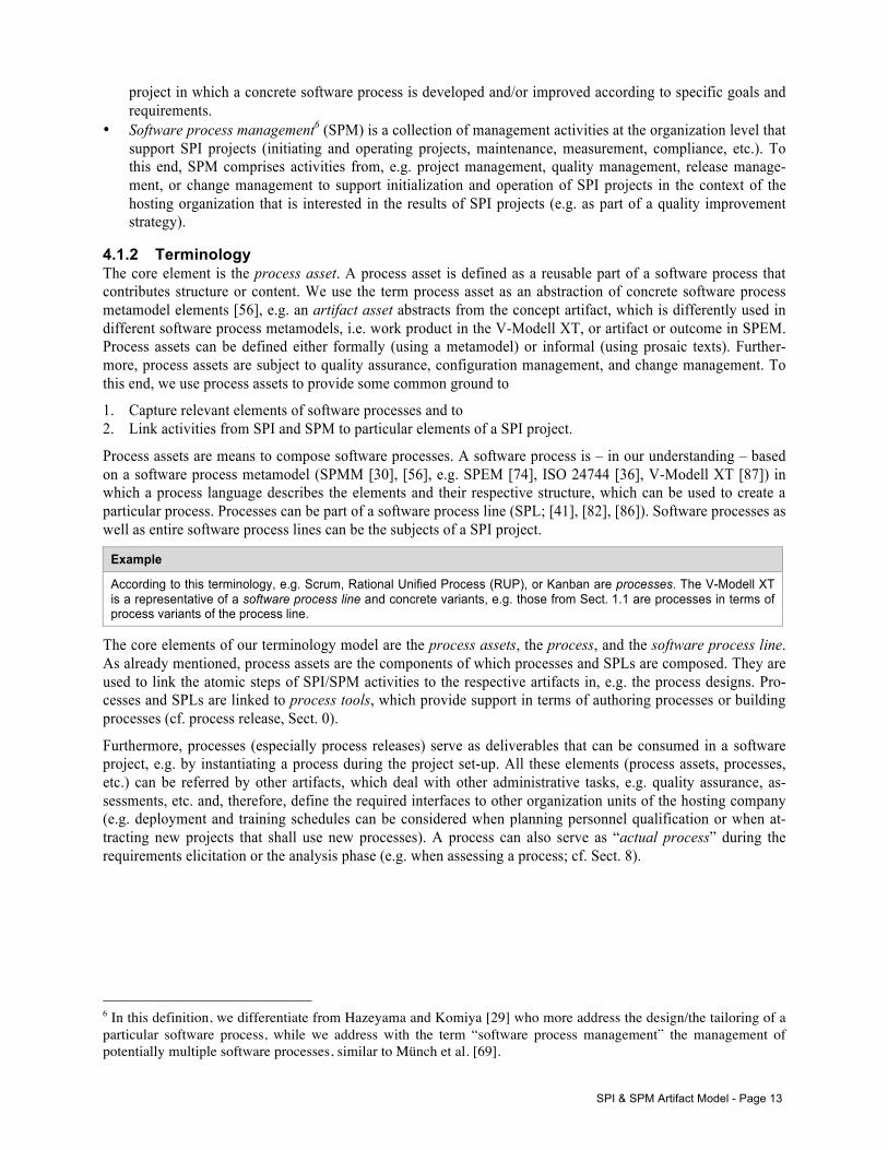
4.1 Terms & Definitions In the following, we briefly introduce the terminology that we use to describe our models on software process improvement and management. Figure 2 shows the terminology as an UML-based [73], [75] metamodel. Please note that we not define another or extend a software process metamodel (SPMM; e.g. [64]). The introduced terminology is used to abstract from the diverse metamodels and to provide a general and reusable approach the develop software processes without preferring a particular software process metamodel.
4.1.1 Definitions Since we present a model that supports software process improvement (SPI) as well as software process man-agement (SPM), we first introduce the definition of these terms.
• Software process improvement (SPI) is an endeavor to develop and/or improve a particular software pro-cess. The endeavor is organized and managed in a project-like style. In other words, a “SPI project” is a
SPI & SPM Artifact Model - Page 13
project in which a concrete software process is developed and/or improved according to specific goals and requirements.
• Software process management6 (SPM) is a collection of management activities at the organization level that support SPI projects (initiating and operating projects, maintenance, measurement, compliance, etc.). To this end, SPM comprises activities from, e.g. project management, quality management, release manage-ment, or change management to support initialization and operation of SPI projects in the context of the hosting organization that is interested in the results of SPI projects (e.g. as part of a quality improvement strategy).
4.1.2 Terminology The core element is the process asset. A process asset is defined as a reusable part of a software process that contributes structure or content. We use the term process asset as an abstraction of concrete software process metamodel elements [56], e.g. an artifact asset abstracts from the concept artifact, which is differently used in different software process metamodels, i.e. work product in the V-Modell XT, or artifact or outcome in SPEM. Process assets can be defined either formally (using a metamodel) or informal (using prosaic texts). Further-more, process assets are subject to quality assurance, configuration management, and change management. To this end, we use process assets to provide some common ground to
1. Capture relevant elements of software processes and to 2. Link activities from SPI and SPM to particular elements of a SPI project.
Process assets are means to compose software processes. A software process is – in our understanding – based on a software process metamodel (SPMM [30], [56], e.g. SPEM [74], ISO 24744 [36], V-Modell XT [87]) in which a process language describes the elements and their respective structure, which can be used to create a particular process. Processes can be part of a software process line (SPL; [41], [82], [86]). Software processes as well as entire software process lines can be the subjects of a SPI project.
Example
According to this terminology, e.g. Scrum, Rational Unified Process (RUP), or Kanban are processes. The V-Modell XT is a representative of a software process line and concrete variants, e.g. those from Sect. 1.1 are processes in terms of process variants of the process line.
The core elements of our terminology model are the process assets, the process, and the software process line. As already mentioned, process assets are the components of which processes and SPLs are composed. They are used to link the atomic steps of SPI/SPM activities to the respective artifacts in, e.g. the process designs. Pro-cesses and SPLs are linked to process tools, which provide support in terms of authoring processes or building processes (cf. process release, Sect. 0).
Furthermore, processes (especially process releases) serve as deliverables that can be consumed in a software project, e.g. by instantiating a process during the project set-up. All these elements (process assets, processes, etc.) can be referred by other artifacts, which deal with other administrative tasks, e.g. quality assurance, as-sessments, etc. and, therefore, define the required interfaces to other organization units of the hosting company (e.g. deployment and training schedules can be considered when planning personnel qualification or when at-tracting new projects that shall use new processes). A process can also serve as “actual process” during the requirements elicitation or the analysis phase (e.g. when assessing a process; cf. Sect. 8).
6 In this definition, we differentiate from Hazeyama and Komiya [29] who more address the design/the tailoring of a particular software process, while we address with the term “software process management” the management of potentially multiple software processes, similar to Münch et al. [69].
Page 14 - The SPI & SPM Artifact Model – A Bird’s Eyes Perspective
Figure 2 SPI model terminology
4.2 The SPI & SPM Artifact Model – A Bird’s Eyes Perspective From our experiences, we derived a compact model of software process management and software process im-provement. In this section, we introduce the model by taking two perspectives:
1. The perspective of a software process improvement (SPI) project 2. The perspective of software process management (SPM) and its embedding into an organization context
At this, software process management comprehends the whole software process-related program/strategy of a company, including all management tasks and interfaces to affected/contributing organization units. SPI is a part of SPM and deals with a particular software process, which is developed, maintained, or improved, in the context of SPM.
In the following, we provide a “bird’s eyes perspective” in which we focus on the key artifacts and the basic relations between the artifacts and the corresponding management disciplines.
4.2.1 Software Process Improvement Projects A software process improvement (SPI) endeavor is a project in which a particular process asset or a process is developed or improved in order to meet certain process requirements.
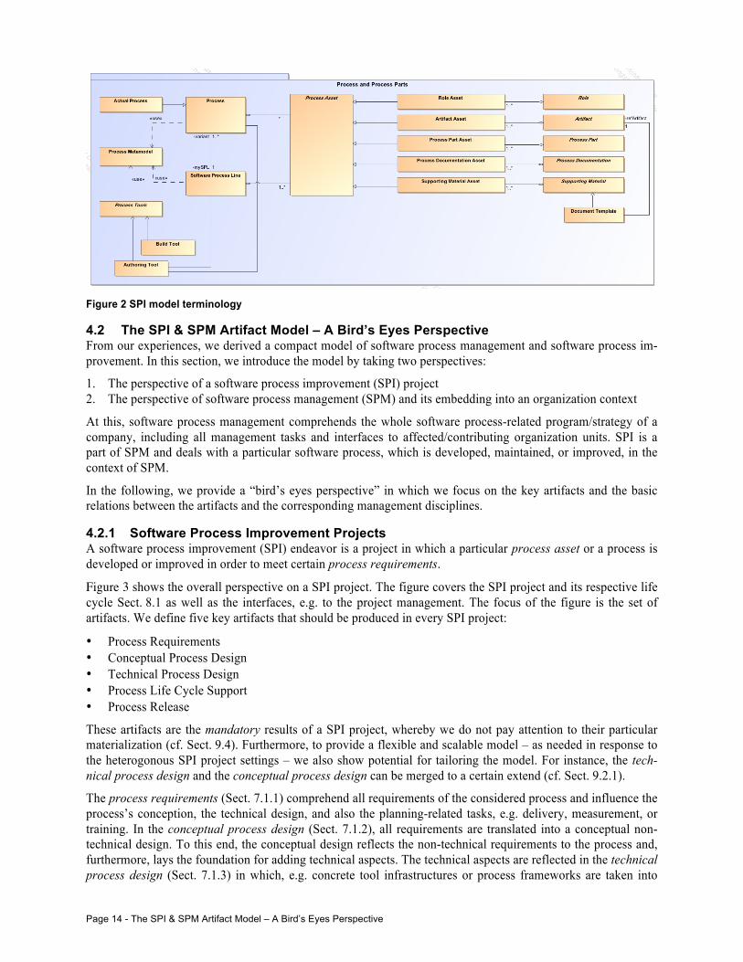
Figure 3 shows the overall perspective on a SPI project. The figure covers the SPI project and its respective life cycle Sect. 8.1 as well as the interfaces, e.g. to the project management. The focus of the figure is the set of artifacts. We define five key artifacts that should be produced in every SPI project:
• Process Requirements • Conceptual Process Design • Technical Process Design • Process Life Cycle Support • Process Release
These artifacts are the mandatory results of a SPI project, whereby we do not pay attention to their particular materialization (cf. Sect. 9.4). Furthermore, to provide a flexible and scalable model – as needed in response to the heterogonous SPI project settings – we also show potential for tailoring the model. For instance, the tech-nical process design and the conceptual process design can be merged to a certain extend (cf. Sect. 9.2.1).
The process requirements (Sect. 7.1.1) comprehend all requirements of the considered process and influence the process’s conception, the technical design, and also the planning-related tasks, e.g. delivery, measurement, or training. In the conceptual process design (Sect. 7.1.2), all requirements are translated into a conceptual non-technical design. To this end, the conceptual design reflects the non-technical requirements to the process and, furthermore, lays the foundation for adding technical aspects. The technical aspects are reflected in the technical process design (Sect. 7.1.3) in which, e.g. concrete tool infrastructures or process frameworks are taken into
SPI & SPM Artifact Model - Page 15
account. A key artifact, which is often left out of scope, is the process life cycle support (Sect. 7.1.4). In the process life cycle support, all definitions and processes are described that support, e.g. the process development, deployment, or training in a SPI project and also during the whole process’s life cycle, e.g. process mainte-nance. Drawing the parallels to software development, the process release (Sect. 0) is the final outcome of a SPI project.
Figure 3 Overall view on software process improvement (SPI) projects.
While the process requirements, the process design documents, and the process release are intuitive outcomes of a SPI project, the process life cycle support document is new (and cannot be explicitly found in literature). The process life cycle support is often implicitly mentioned. However, in terms of a sustainable and long-term SPM the process life cycle support is a key artifact that lays the foundation for all activities that are related to, e.g. the personnel’s training, process release/deployment strategies, or process evaluation. Figure 3 shows the corre-sponding artifacts, which are labeled optional depending, e.g. on the project’s size. For instance, if the trigger to initiate a SPI endeavor is the need to optimize a process for only one project, explicitly created life cycle sup-port documents/plan might be unnecessary since the process is potentially thrown away after the project’s end.
Figure 3 also shows artifacts that complement a SPI project and shape the interface to the hosting organization hence SPI requires a management commitment [2]. On the hand, there are the administrative artifacts:
• Vision • Contract (which also serves as project assignment) • Quality Assurance (QA) Manual • Project Manual
In these artifacts, the basic goals and agreements regarding the SPI project are documented (Vision and Con-tract). The QA Manual and the Project Manual comprehend all administrative agreements, definitions, and procedures in order to provide a meaningful project organization and an efficient quality management/assurance in the project (according to Birk and Pfahl [9]). To this end, a project management approach has to be defined, including all corresponding activities, e.g. estimating, planning, controlling, or reporting. Also, a quality man-agement approach needs to be defined in order to organize the quality assurance activities in the project, identi-fication of artifacts to be quality assured, when and how to create test specifications, when and how to test.
Since our model was inspired by many years of work in the context of the V-Modell XT, which considers pro-ject management and quality assurance to be mandatory tasks in every project, we also demand a minimum of
Analysis Conceptualization Realization Deployment
Project Set-Up SPI Project and Life Cycle Model
Process Requirements
Conceptual Process Design
Technical Process Design
Process Release
Process Life Cycle Support
Vision
Contract
QA Manual
Project Manual
Deployment Plan
Training Plan
Measurement Plan
User Evaluation Plan
Project Plan
QA Plan
Mandatory Results
Optional Results
Test Spec./Protocol Test Spec./Protocol Test Spec./Protocol
continuous planning and controlling
continuous improvement
Page 16 - The SPI & SPM Artifact Model – A Bird’s Eyes Perspective
project management (represented by a Project Manual and a Project Plan) and quality assurance (represented by a QA Manual and a QA Plan) for SPI projects. Figure 3 highlights the importance of these disciplines, e.g. by assigning quality assurance artifacts to the SPI key artifacts. In other words, each key artifact from the SPI model has to be quality assured, which means QA has to be planned and organized (constructive QA), and QA activities have to be executed (analytical QA) in order to reach a quality gate (each phase of the life cycle model has assigned at least one quality gate).
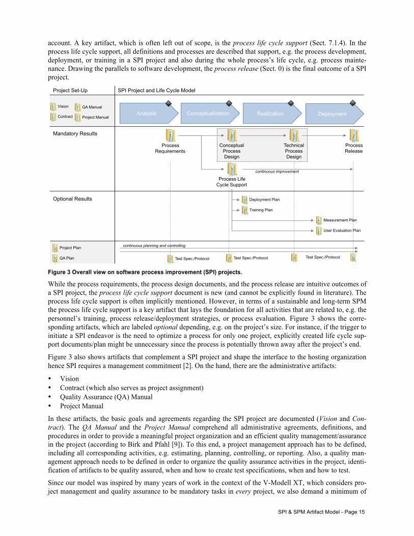
4.2.2 Software Process Management While SPI addresses one particular (sub-)process, software process management (SPM) is defined as the set of management disciplines enabling and supporting organizations to initiate (comprehensive) SPI endeavors.
Figure 4 Overall view on software process management (SPM) and its relation to SPI- and software projects.
Figure 4 shows the overall view on software process management and its core disciplines enabling and support-ing organizations to initiate and operate single SPI endeavors or comprehensive SPI programs. Figure 4 also shows the relation between a SPI project (Figure 3), the organization that hosts the SPI project, and the software projects that, finally, consume the developed/improved software processes. In the following, we briefly describe the approach in general.
Initiating a SPI Project. A SPI project is initiated (Figure 4, upper part) by the host organization by collecting requirements and creating a vision. If the process under consideration is subject of an improvement, change or feature requests have also be taken into account. Requirements (including change requests) always refer to a particular process variant (precisely to process assets that are consumed by process variants, cf. Sect. 8.3.2.2), which is, e.g. a standard process that needs to be customized, or an already deployed variant (of a process line).
Dep
loym
ent P
lan
Trai
ning
Pla
n
Mea
sure
men
t Pla
n
Use
r Eva
luat
ion
Pla
n
Process Release
Process Life Cycle Support
SPI Project for one process Software Project
Feedback, Evaluation
Publish
Use
Evaluate user perspective
Evaluate engineering & management perspective
Vision
Quality(Management(
SPM
Change(Management(
Project(Management( Release(Management(
Software Process (Line)
Actual Process (Organization)
Configura8on(Management(
part of
Input: Assessments, Audits, Evaluation
Input: (common) Quality Assurance
Changes etc.
Contract/ Project Assignment
Initiate & define a SPI project
Deploy & maintain a new process (release)
SPI & SPM Artifact Model - Page 17
A contract (a project assignment) ensures that all required resources (time, personnel, funding, etc.) are made available. Those are the required inputs to initiate a SPI project.
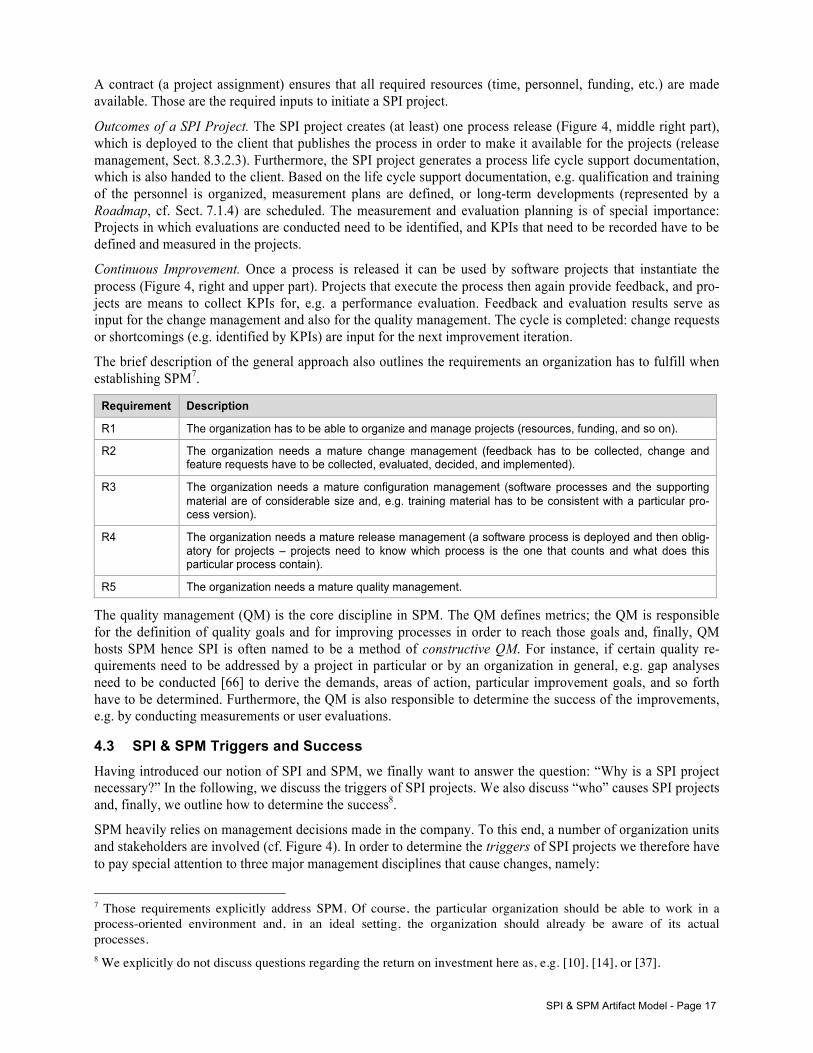
Outcomes of a SPI Project. The SPI project creates (at least) one process release (Figure 4, middle right part), which is deployed to the client that publishes the process in order to make it available for the projects (release management, Sect. 8.3.2.3). Furthermore, the SPI project generates a process life cycle support documentation, which is also handed to the client. Based on the life cycle support documentation, e.g. qualification and training of the personnel is organized, measurement plans are defined, or long-term developments (represented by a Roadmap, cf. Sect. 7.1.4) are scheduled. The measurement and evaluation planning is of special importance: Projects in which evaluations are conducted need to be identified, and KPIs that need to be recorded have to be defined and measured in the projects.
Continuous Improvement. Once a process is released it can be used by software projects that instantiate the process (Figure 4, right and upper part). Projects that execute the process then again provide feedback, and pro-jects are means to collect KPIs for, e.g. a performance evaluation. Feedback and evaluation results serve as input for the change management and also for the quality management. The cycle is completed: change requests or shortcomings (e.g. identified by KPIs) are input for the next improvement iteration.
The brief description of the general approach also outlines the requirements an organization has to fulfill when establishing SPM7.
Requirement Description
R1 The organization has to be able to organize and manage projects (resources, funding, and so on).
R2 The organization needs a mature change management (feedback has to be collected, change and feature requests have to be collected, evaluated, decided, and implemented).
R3 The organization needs a mature configuration management (software processes and the supporting material are of considerable size and, e.g. training material has to be consistent with a particular pro-cess version).
R4 The organization needs a mature release management (a software process is deployed and then oblig-atory for projects – projects need to know which process is the one that counts and what does this particular process contain).
R5 The organization needs a mature quality management.
The quality management (QM) is the core discipline in SPM. The QM defines metrics; the QM is responsible for the definition of quality goals and for improving processes in order to reach those goals and, finally, QM hosts SPM hence SPI is often named to be a method of constructive QM. For instance, if certain quality re-quirements need to be addressed by a project in particular or by an organization in general, e.g. gap analyses need to be conducted [66] to derive the demands, areas of action, particular improvement goals, and so forth have to be determined. Furthermore, the QM is also responsible to determine the success of the improvements, e.g. by conducting measurements or user evaluations.
4.3 SPI & SPM Triggers and Success Having introduced our notion of SPI and SPM, we finally want to answer the question: “Why is a SPI project necessary?” In the following, we discuss the triggers of SPI projects. We also discuss “who” causes SPI projects and, finally, we outline how to determine the success8.
SPM heavily relies on management decisions made in the company. To this end, a number of organization units and stakeholders are involved (cf. Figure 4). In order to determine the triggers of SPI projects we therefore have to pay special attention to three major management disciplines that cause changes, namely:
7 Those requirements explicitly address SPM. Of course, the particular organization should be able to work in a process-oriented environment and, in an ideal setting, the organization should already be aware of its actual processes. 8 We explicitly do not discuss questions regarding the return on investment here as, e.g. [10], [14], or [37].
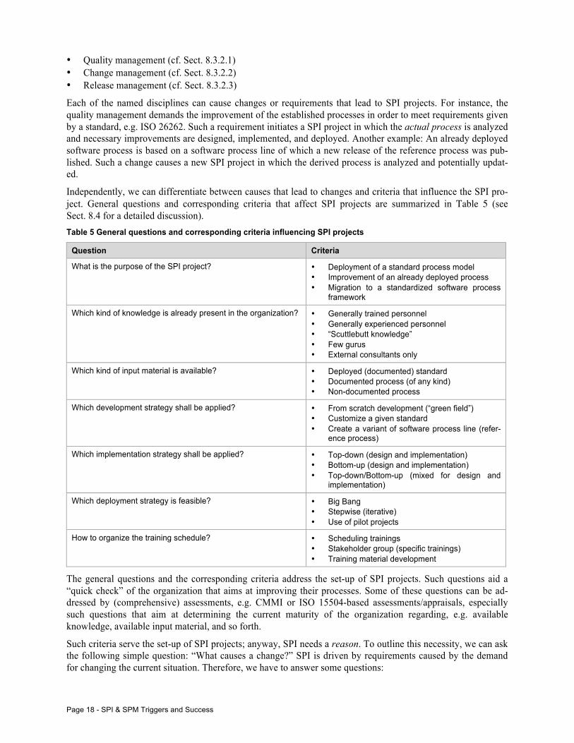
Page 18 - SPI & SPM Triggers and Success
• Quality management (cf. Sect. 8.3.2.1) • Change management (cf. Sect. 8.3.2.2) • Release management (cf. Sect. 8.3.2.3)
Each of the named disciplines can cause changes or requirements that lead to SPI projects. For instance, the quality management demands the improvement of the established processes in order to meet requirements given by a standard, e.g. ISO 26262. Such a requirement initiates a SPI project in which the actual process is analyzed and necessary improvements are designed, implemented, and deployed. Another example: An already deployed software process is based on a software process line of which a new release of the reference process was pub-lished. Such a change causes a new SPI project in which the derived process is analyzed and potentially updat-ed.
Independently, we can differentiate between causes that lead to changes and criteria that influence the SPI pro-ject. General questions and corresponding criteria that affect SPI projects are summarized in Table 5 (see Sect. 8.4 for a detailed discussion). Table 5 General questions and corresponding criteria influencing SPI projects
Question Criteria
What is the purpose of the SPI project? • Deployment of a standard process model • Improvement of an already deployed process • Migration to a standardized software process
framework
Which kind of knowledge is already present in the organization? • Generally trained personnel • Generally experienced personnel • “Scuttlebutt knowledge” • Few gurus • External consultants only
Which kind of input material is available? • Deployed (documented) standard • Documented process (of any kind) • Non-documented process
Which development strategy shall be applied? • From scratch development (“green field”) • Customize a given standard • Create a variant of software process line (refer-
ence process)
Which implementation strategy shall be applied? • Top-down (design and implementation) • Bottom-up (design and implementation) • Top-down/Bottom-up (mixed for design and
implementation)
Which deployment strategy is feasible? • Big Bang • Stepwise (iterative) • Use of pilot projects
How to organize the training schedule? • Scheduling trainings • Stakeholder group (specific trainings) • Training material development
The general questions and the corresponding criteria address the set-up of SPI projects. Such questions aid a “quick check” of the organization that aims at improving their processes. Some of these questions can be ad-dressed by (comprehensive) assessments, e.g. CMMI or ISO 15504-based assessments/appraisals, especially such questions that aim at determining the current maturity of the organization regarding, e.g. available knowledge, available input material, and so forth.
Such criteria serve the set-up of SPI projects; anyway, SPI needs a reason. To outline this necessity, we can ask the following simple question: “What causes a change?” SPI is driven by requirements caused by the demand for changing the current situation. Therefore, we have to answer some questions:
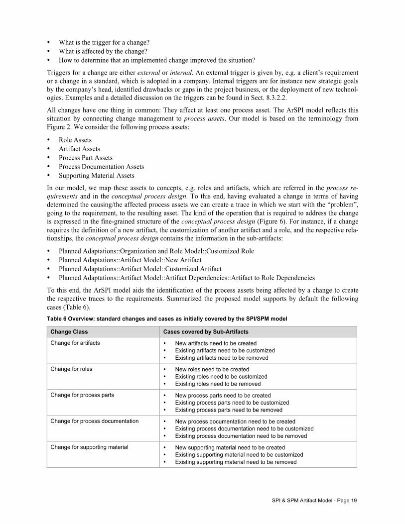
SPI & SPM Artifact Model - Page 19
• What is the trigger for a change? • What is affected by the change? • How to determine that an implemented change improved the situation?
Triggers for a change are either external or internal. An external trigger is given by, e.g. a client’s requirement or a change in a standard, which is adopted in a company. Internal triggers are for instance new strategic goals by the company’s head, identified drawbacks or gaps in the project business, or the deployment of new technol-ogies. Examples and a detailed discussion on the triggers can be found in Sect. 8.3.2.2.
All changes have one thing in common: They affect at least one process asset. The ArSPI model reflects this situation by connecting change management to process assets. Our model is based on the terminology from Figure 2. We consider the following process assets:
• Role Assets • Artifact Assets • Process Part Assets • Process Documentation Assets • Supporting Material Assets
In our model, we map these assets to concepts, e.g. roles and artifacts, which are referred in the process re-quirements and in the conceptual process design. To this end, having evaluated a change in terms of having determined the causing/the affected process assets we can create a trace in which we start with the “problem”, going to the requirement, to the resulting asset. The kind of the operation that is required to address the change is expressed in the fine-grained structure of the conceptual process design (Figure 6). For instance, if a change requires the definition of a new artifact, the customization of another artifact and a role, and the respective rela-tionships, the conceptual process design contains the information in the sub-artifacts:
• Planned Adaptations::Organization and Role Model::Customized Role • Planned Adaptations::Artifact Model::New Artifact • Planned Adaptations::Artifact Model::Customized Artifact • Planned Adaptations::Artifact Model::Artifact Dependencies::Artifact to Role Dependencies
To this end, the ArSPI model aids the identification of the process assets being affected by a change to create the respective traces to the requirements. Summarized the proposed model supports by default the following cases (Table 6). Table 6 Overview: standard changes and cases as initially covered by the SPI/SPM model
Change Class Cases covered by Sub-Artifacts
Change for artifacts • New artifacts need to be created • Existing artifacts need to be customized • Existing artifacts need to be removed
Change for roles • New roles need to be created • Existing roles need to be customized • Existing roles need to be removed
Change for process parts • New process parts need to be created • Existing process parts need to be customized • Existing process parts need to be removed
Change for process documentation • New process documentation need to be created • Existing process documentation need to be customized • Existing process documentation need to be removed
Change for supporting material • New supporting material need to be created • Existing supporting material need to be customized • Existing supporting material need to be removed
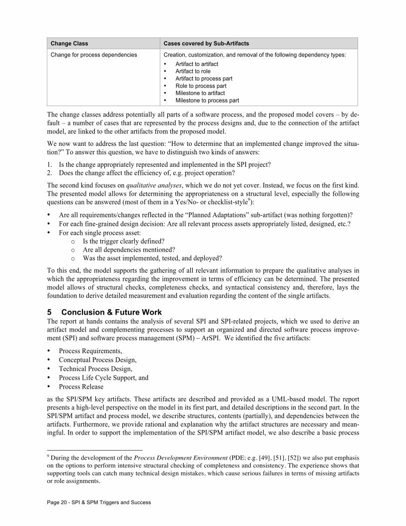
Page 20 - SPI & SPM Triggers and Success
Change Class Cases covered by Sub-Artifacts
Change for process dependencies Creation, customization, and removal of the following dependency types: • Artifact to artifact • Artifact to role • Artifact to process part • Role to process part • Milestone to artifact • Milestone to process part
The change classes address potentially all parts of a software process, and the proposed model covers – by de-fault – a number of cases that are represented by the process designs and, due to the connection of the artifact model, are linked to the other artifacts from the proposed model.
We now want to address the last question: “How to determine that an implemented change improved the situa-tion?” To answer this question, we have to distinguish two kinds of answers:
1. Is the change appropriately represented and implemented in the SPI project? 2. Does the change affect the efficiency of, e.g. project operation?
The second kind focuses on qualitative analyses, which we do not yet cover. Instead, we focus on the first kind. The presented model allows for determining the appropriateness on a structural level, especially the following questions can be answered (most of them in a Yes/No- or checklist-style9):
• Are all requirements/changes reflected in the “Planned Adaptations” sub-artifact (was nothing forgotten)? • For each fine-grained design decision: Are all relevant process assets appropriately listed, designed, etc.? • For each single process asset:
o Is the trigger clearly defined? o Are all dependencies mentioned? o Was the asset implemented, tested, and deployed?
To this end, the model supports the gathering of all relevant information to prepare the qualitative analyses in which the appropriateness regarding the improvement in terms of efficiency can be determined. The presented model allows of structural checks, completeness checks, and syntactical consistency and, therefore, lays the foundation to derive detailed measurement and evaluation regarding the content of the single artifacts.
5 Conclusion & Future Work The report at hands contains the analysis of several SPI and SPI-related projects, which we used to derive an artifact model and complementing processes to support an organized and directed software process improve-ment (SPI) and software process management (SPM) – ArSPI. We identified the five artifacts:
• Process Requirements, • Conceptual Process Design, • Technical Process Design, • Process Life Cycle Support, and • Process Release
as the SPI/SPM key artifacts. These artifacts are described and provided as a UML-based model. The report presents a high-level perspective on the model in its first part, and detailed descriptions in the second part. In the SPI/SPM artifact and process model, we describe structures, contents (partially), and dependencies between the artifacts. Furthermore, we provide rational and explanation why the artifact structures are necessary and mean-ingful. In order to support the implementation of the SPI/SPM artifact model, we also describe a basic process
9 During the development of the Process Development Environment (PDE; e.g. [49], [51], [52]) we also put emphasis on the options to perform intensive structural checking of completeness and consistency. The experience shows that supporting tools can catch many technical design mistakes, which cause serious failures in terms of missing artifacts or role assignments.
Conclusion & Future Work - Page 21
life cycle and a set of activities supporting the artifacts’ creation. Finally, paying attention to the different con-texts in which SPI/SPM can occur, we present options for tailoring the presented model.
The report at hands lays the foundation to drive further research on SPI and SPM. Hence, the following activi-ties for future work are necessary/planned:
1. Implement the presented model as an applicable software process, e.g. based on EPF or the V-Modell XT. 2. Analyze the implications of the artifact model on standard assessment and maturity models such as CMMI
or ISO 15504, and design an extension of these standards. 3. Empirically evaluate the presented approach, e.g. in terms of general feasibility, support for clearly defining
measurable success criteria and determination of goal achievements.
Especially the points 2 and 3 are of interest: Since CMMI and ISO 15504 are (almost) free of artifacts and focus on collecting practices and defining activities, the extension of these approaches by artifact models could help the improvement and applicability of such methods. Process engineers and process owners can agree on arti-facts reflecting and systematically documenting designs and outcomes in order to aid a long-term improvement and process management.
The 3rd point is crucial and leads to the questions “How can the improvement method improved?” – And how can the improvement determined. An evaluation strategy needs to be worked out in which (a) the feasibility of the presented model can be tested, and (b) the findings can be used to improve the presented model. Such an evaluation strategy thus addresses different aspects of SPI: successful improvement of the process under con-sideration, and success and appropriateness of the improvement method itself.
Page 22 - SPI & SPM Triggers and Success
6 References [1] Aaen, I. Software process improvement: Blueprints versus recipes. IEEE Software 20, 5 (2003), 86–93. [2] Abrahamsson, P. Is management commitment a necessity after all in software process improvement? In 26th Eu-
romicro Conference on Software Engineering and Advanced Applications (2000), pp. 246–253. [3] Allison, I. Organizational Factors Shaping Software Process Improvement in Small-Medium Sized Software
Teams: A Multi-Case Analysis. In 7th International Conference on the Quality of Information and Communica-tions Technology (QUATIC). (2010), pp. 418–423.
[4] Armbrust, O., Ebell, J., Hammerschall, U., Münch, J., Thoma, D. Experiences and results from tailoring and deploying a large process standard in a company. Software Process: Improvement and Practice 13, 4 (2008), 301–309.
[5] Barbieri, A., Fugetta, A., Lavazza, L., Tagliavini, M. DynaMan: A tool to improve software process management through dynamic simulation. In 5th International Workshop on Computer-Aided Software Engineering, (1992), pp. 166–175.
[6] Berander, P., Wohlin, C. Identification of key factors in software process management - a case study. In Interna-tional Symposium on Empirical Software Engineering (ISESE). 2003 (2003), pp. 316–325.
[7] Biffl, S., Winkler, D., Höhn, R., Wetzel, H. Software process improvement in Europe: potential of the new V-Modell XT and research issues. Software Process: Improvement and Practice 11, 3 (2006).
[8] Bin Basri, S., O’Connor, R. V. Organizational commitment towards software process improvement: An Irish software VSEs case study. International Symposium in Information Technology (ITSim), (2010), 1456–1461.
[9] Birk, A., Pfahl, D. A Systems Perspective on Software Process Improvement. In Product Focused Software Pro-cess Improvement. Springer, 2002, pp. 4–18.
[10] Boria, J. L. A framework for understanding software process improvement’s return on investment. In Portland International Conference on Management and Technology Innovation in Technology Management - The Key to Global Leadership. PICMET ’97: (1997), pp. 847–851.
[11] Börjesson, A., Mathiassen, L. Successful process implementation. IEEE Software 21, 4 (2004), 36–44. [12] Bösl, A., Ebell, J., Kuhrmann, M., Rausch, A. Der Einsatz des V-Modell XT bei Witt Weiden: Nutzen und
Kosten. In OBJEKTspektrum, pp. 31--37, SIGS Datacom, 2008 (in German). [13] Cater-Steel, A. An evaluation of software development practice and assessment-based process improvement in
small software development firms - USQ ePrints. Ph.D. thesis, 2004. [14] Coleman, G., O’Connor, R. Investigating software process in practice: A grounded theory perspective. Journal of
Systems and Software 81, 5 (May 2008), 772–784. [15] Costache, D., Kalus, G., Kuhrmann, M. Design and Validation of Feature-based Process Model Tailoring – A
Sample Implementation of PDE. In 8th European Software Engineering Conference and the ACM SIGSOFT Sym-posium on the Foundations of Software Engineering (ESEM/FSE). (2011), ACM, pp. 464–467.
[16] Culver-Lozo, K. Rapid iteration in software process improvement: experience report. In 3rd International Confer-ence on the Software Process. (1994), pp. 79–84.
[17] Curtis, B. Software Process Improvement: Methods and Lessons Learned. In 19th International Conference on Software Engineering. (1997), pp. 624–625.
[18] Curtis, B. Software process improvement: best practices and lessons learned. In International Conference on Software Engineering. (2000), p. 828.
[19] Eberlein, A., Jiang, L. Description of a process development methodology. Software Process: Improvement and Practice 12, 1 (2007), 101–118.
[20] Frailey, D. J. Defining a Corporate-Wide Software Process. In 1st International Conference on the Software Pro-cess, (1991), IEEE, pp. 113–121.
[21] Friedrich, J., Hammerschall, U., Kuhrmann, M., Sihling, M. Das V-Modell XT - Für Projektleiter und QS-Verantwortliche kompakt und übersichtlich, 2. ed., series Informatik im Fokus. Springer, 2009. (in German)
[22] García, F., Piattini, M., Ruiz, F., Canfora, G., Visaggio, C. FMESP: Framework for the modeling and evaluation of software processes. Journal of Systems Architecture 52, 11 (Nov. 2006), 627–639.
[23] García, I., Pachece, C., Mendoza, E., Calvo-Manzano, J., Cuevaz, G., San Feliu, T. Managing the software pro-cess with a software process improvement tool in a small enterprise. Journal of Software Maintenance and Evolu-tion: Research and Practice 24, 5 (July 2010), 481–491.
[24] Green, G. C., Hevner, A. R., Collins, R. W. The impacts of quality and productivity perceptions on the use of software process improvement innovations. Information and Software Technology 47, 8 (2005).
[25] Haley, T. J. Software process improvement at Raytheon. IEEE Software, 13, 6 (1996), 33–41. [26] Hall, T., Rainer, A., Baddoo, N. Implementing software process improvement: an empirical study. Software
Process: Improvement and Practice 7, 1 (2002), 3–15.
References - Page 23
[27] Hammerschall, U., Kuhrmann, M., Sihling, M., Ternité, T. Strategischer Vorteil - Das V-Modell XT an Un-ternehmen anpassen (Teil 2). In iX, pp. 142--145, number 05/07, Heise, 2007 (in German).
[28] Hardgrave, B. C., Armstrong, D. J. Software process improvement: It’s a journey not a destination. Communica-tions of the ACM 48, 11 (2005), 93.
[29] Hazeyama, A., Komiya, S. A process model for software process management. In 4th International Conference on Software Engineering and Knowledge Engineering. (1992), pp. 582–589.
[30] Henderson-Sellers, B., Gonzalez-Perez, C. A comparison of four process metamodels and the creation of a new generic standard. Information and Software Technology 47, 1 (2005), 49 – 65.
[31] Henderson-Sellers, B., Stallinger, F., Lefever, B. Bridging the gap from process modelling to process assessment: the OOSpice process specification for component-based software engineering. In 28th Euromicro Conference. (2002), pp. 324 – 331.
[32] Horvat, R. V., Rozman, I., Györkös, J. Managing the Complexity of SPI in Small Companies. Software Process: Improvement and Practice. (2000), 45–54.
[33] Jakjoud, A., Zrikem, M., Ayadi, A., Baron, C., Auriol, G. SySPEM: Proposing a coherent model for systems engineering processes. In International Conference on Computer Applications and Industrial Electronics (IC-CAIE) (2011), IEEE, pp. 367–372.
[34] Jo, J.-H., Choi, H.-J. A reflective case study of software process improvement for a small- scale project. In 4th Annual ACIS International Conference on Computer and Information Science. (2005), pp. 314–319.
[35] Joh, F., Mosley, V. An innovative approach to software process improvement. In Proceedings of the IEEE Aero-space and Electronics Conference. (1989), pp. 1581–1584.
[36] Joint Technical Committee ISO/IEC JTC 1, SC 7. Software engineering – metamodel for development methodol-ogies. Tech. Rep. ISO/IEC 24744:2007, International Organization for Standardization, 2007.
[37] Jones, C. The economics of software process improvement. IEEE Computer 29, 1 (1996), 95–97. [38] Kalito, T., Kinnula, A. Deploying the Defined SW Process. Software Process: Improvement and Practice (2000),
65–83. [39] Kalus, G., Kuhrmann, M. Criteria for Software Process Tailoring: A Systematic Review. In International Confer-
ence on Software and Systems Process (ICSSP), pp. 171--180, ACM Press, 2013. [40] Keto, H., Makinen, T., Linna, P. Eliciting Process Conception contradictions in soft- ware process improvement.
In Technology Management in the Energy Smart World (PICMET. (2011), pp. 1–6. [41] Kuhrmann, M. Konstruktion modularer Vorgehensmodelle. PhD thesis, Technische Universität München, 2008.
(in German) [42] Kuhrmann, M. CollabXT: Kollaboration und verteilte Entwicklung mit dem V-Modell XT. In OBJEKTspektrum,
pp. 61--65, SIGS Datacom, 2008 (in German). [43] Kuhrmann, M. User Assistance during Domain-specific Language Design. In ICSE 2011 Workshop on Flexible
Modeling Tools (FlexiTools), ACM Press, 2011. [44] Kuhrmann, M., Hammerschall, U. Anpassung des V-Modell XT – Leitfaden zur organisationsspezifischen
Anpassung des V-Modell XT. Technical Report, Technische Universität München, TUM-I0831, 2008 (in Ger-man).
[45] Kuhrmann, M., Hammerschall, U., Ternité, T., Sihling, M. Individueller Standard - Das V-Modell XT an Un-ternehmen anpassen (Teil 1). In , iX, pp. 134--138, number 04/07, Heise, 2007 (in German).
[46] Kuhrmann, M., Kalus, G. Providing Integrated Development Processes for Distributed Development Environ-ments. In Workshop on Supporting Distributed Team Work at Computer Supported Cooperative Work (CSCW), 2008.
[47] Kuhrmann, M., Kalus, G., Chroust, G. Tool-Support for Software Development Process. In Business Science Reference, ch. 11, pp. 213-231, IGI Global, 2009.
[48] Kuhrmann, M., Kalus, G., Diernhofer, N. Generating Tool-based Process-Environments from formal Process Model Descriptions – Concepts, Experiences and Samples. In Proceedings of the IASTED International Confer-ence on Software Engineering (SE) as part of the 26th IASTED International Multi-Conference on Applied In-formatics, ACTA Press, 2008.
[49] Kuhrmann, M., Kalus, G., Knapp, A. Rapid Prototyping for Domain-specific Languages – From Stakeholder Analyses to Modelling Tools. In Enterprise Modelling and Information Systems Architectures: Special Issue on Design, Implementation and Evaluation of Modelling Tools, pp. 62--74, (Online), 2013.
[50] Kuhrmann, M., Kalus, G., Then, M. The Process Enactment Tool Framework – Transformation of Software Pro-cess Models to Prepare Enactment. In Science of Computer Programming, Elsevier, 2012.
[51] Kuhrmann, M., Kalus, G., Then, M., Wachtel, E. From Design to Tools: Process Modeling and Enactment with PDE and PET. In 3rd International Workshop on Academic Software Development Tools and Techniques (WASDeTT-3), co-located with the 25th IEEE/ACM International Conference on Automated Software Engineering (ASE), (Online), 2010.
Page 24 - SPI & SPM Triggers and Success
[52] Kuhrmann, M., Kalus, G., Wachtel, E., Broy, M. Visual Process Model Design using Domain-specific Lan-guages. In SPLASH Workshop on Flexible Modeling Tools, ACM, 2010.
[53] Kuhrmann, M., Lange, C., Schnackenburg, A. A Survey on the Application of the V-Modell XT in German Gov-ernment Agencies. In 18th Conference on European System & Software Process Improvement and Innovation (EuroSPI), pp. 49 ff., CCIS, Springer, 2011.
[54] Kuhrmann, M., Méndez Fernández, D., Knapp, A. A First Investigation About the Perceived Value of Process Engineering and Process Consumption. In 14th International Conference on Product Focused Software Develop-ment and Process Improvement (PROFES), pp. 138--152, LNCS, Springer-Verlag, 2013.
[55] Kuhrmann, M., Méndez Fernández, D., Münch, J. Teaching Software Process Modeling. In 35th International Conference on Software Engineering (ICSE 2013), pp. 1138--1147, IEEE, 2013.
[56] Kuhrmann, M., Méndez Fernández, D., Steenweg, R. Systematic Software Process Development: Where Do We Stand Today? In International Conference on Software and Systems Process (ICSSP), pp. 166--170, ACM Press, 2013.
[57] Kuhrmann, M., Niebuhr, D., Rausch, A. Application of the V-Modell XT - Report from A Pilot Project. In Inter-national Software Process Workshop (SPW), Lecture Notes in Computer Science, Springer, 2005.
[58] Kuhrmann, M., Ternité, T. Including the Microsoft Solution Framework as an agile method into the V-Modell XT. In 1st International Workshop on Evaluation of Novel Approaches to Software Engineering (ENASE), 2006.
[59] Kuhrmann, M., Ternité, T., Friedrich, J. Das V-Modell XT anpassen. Informatik im Fokus. Springer, 2011. (in German)
[60] Lavalée, M., Robillard, P.-N. Do software process improvements lead to ISO 9126 architectural quality factor improvement. In 8th International Workshop on Software Quality, (2011).
[61] Mäkinen, T., Varkoi, T. Assessment driven process modeling for software process improvement. In Portland International Conference on Management of Engineering & Technology. (2008), pp. 1570–1575.
[62] Malheiros, V., Paim, F. R., Mendoca, M. Continuous process improvement at a large software organization. Soft-ware Process: Improvement and Practice 14, 2 (Mar. 2009), 65–83.
[63] Martínez-Ruiz, T., García, F., Piattini, M., Münch, J. Modelling software process variability: an empirical study. IET Software 5, 2 (2011), 172.
[64] Martins, P., Da Silva, A. Pit-ProcessM: A software process improvement meta-model. In 7th International Con-ference on the Quality of Information and Communications Technology (QUATIC). (2010), pp. 453 –458.
[65] McLoughlin, F. The Rosetta Stone Methodology – A Benefits Driven Approach to Software Process Improvement. PhD thesis, University of Limerick, 2010.
[66] D. Mendez Fernandez, R. Wieringa. Improving Requirements Engineering by Artefact Orientation. In 14th Inter-national Conference on Product-Focused Software Development and Process Improvement (PROFES), Springer, 2013.
[67] Minghui, W., Jing, Y., Chunyan, Y. A methodology and its support environment for benchmark-based adaptable software process improvement. In International Conference on Systems, Man and Cybernetics. (2004), pp. 5183–5188.
[68] Müller, S. D., Mathiassen, L., Balshøj, H. H. Software Process Improvement as organizational change: A meta-phorical analysis of the literature. Journal of Systems and Software 83, 11 (2010), 2128–2146.
[69] Münch, J., Armbrust, O., Sotó, M., Kowalczyk, M. Software Process Definition and Management. Springer, 2012.
[70] Ocampo, A., Sotó, M. Connecting the Rationale for Changes to the Evolution of a Process. In International Con-ference on Product-Focused Software Process Improvement (PROFES), 2007.
[71] Ocampo, A., Münch, J., Riddle, W. Incrementally Introducing Process Model Rationale Support in an Organiza-tion. In International Conference on Software Process (ICSP), 2009.
[72] Ocampo, A., and Münch, J. Rationale modeling for software process evolution. In Software Process, vol. 14, no. 2, pp. 85–105, 2009.
[73] OMG. Unified Modeling Language (UML): Infrastructure – Version 2.1.1. Object Management Group, 2007. [74] OMG. Software & Systems Process Engineering Metamodel Specification (SPEM) Version 2.0. Object Manage-
ment Group, 2008. [75] OMG. Unified Modeling Language (UML): Superstructure Version 2.2. Object Management Group, 2009. [76] Osterweil, L. Software processes are software too. In 9th International Conference on Software Engineering
(ICSE), 1987. [77] Parnas, D. L., Clemens, P. C. A rational design process: How and why to fake it. IEEE Transactions on Software
Engineering, 1986. [78] Rainer, A., Hall, T. An analysis of some ’core studies’ of software process improvement. Software Process: Im-
provement and Practice 6, 4 (2002), 169–187.
References - Page 25
[79] Rausch, A., Bartelt, C., Ternité, T., Kuhrmann, M. The V-Modell XT Applied– Model-Driven and Document-Centric Development. In 3rd World Congress for Software Quality, VOLUME III, Online Supplement, pp. 131 - 138, 2005.
[80] Riemenschneider, C. K., Hardgrave, B. C., Davis, F. D. Explaining Software Developer Acceptance of Method-ologies: A Comparison of Five Theoretical Models. IEEE Transactions on Software Engineering 28, 12 (2002).
[81] Rodenbach, E., Latum, F., Solingen, R. SPI – A Guarantee for Success? – A Reality Story from Industry. In Product Focused Software Process Improvement, Springer, 2000, pp. 216–231.
[82] Rombach, D. Integrated Software Process and Product Lines. In International Software Process Workshop (SPW), 2005.
[83] Stallinger, F., Plösch, R., Pomberger, G., Vollmar, J. Integrating ISO/IEC 15504 conformant process assessment and organizational reuse enhancement. Journal of Software Maintenance and Evolution: Research and Practice, 2010.
[84] Stelzer, D., Mellis, W. Success Factors of Organizational Change in Software Process Improvement. Software Process: Improvement and Practice (1998), 227–250.
[85] Steenweg, R., Kuhrmann, M., Méndez Fernández, D. Software Engineering Process Metamodels - A Literature Review. Technical Report, Technische Universität München, TUM-I1220, 2012.
[86] Ternité, T. Variability of Development Models. PhD thesis, Technische Universität Clausthal, 2010. [87] Ternité, T., Kuhrmann, M. Das V-Modell XT 1.3 Metamodell. Tech. Rep. TUM-I0905, Technische Universität
München, 2009. (in German) [88] Tosun, A., Bener, A., Turhan, B. Implementation of a Software Quality Improvement Project in an SME: A Be-
fore and After Comparison. In Euromicro Conference on Software Engineering and Advanced Applications, (2009), pp. 203–209.
[89] Umarji, M., Seaman, C.. Predicting acceptance of Software Process Improvement, In Human and Social Factors of Software Engineering (HSSE), ACM, 2005.
[90] Viana, D., Conte, T., Vilela, D., De Souza, C. R. B., Santos, G., Prikladnicki, R. The influence of human aspects on software process improvement: Qualitative research findings and comparison to previous studies. In 16th In-ternational Conference on Evaluation & Assessment in Software Engineering (EASE), (2012), pp. 121–125.
[91] Wang, Y., King, G., Dorling, A., Wickberg, H. A Unified Framework for the Software Engineering Process Sys-tem Standards and Models. Software Engineering (1999).
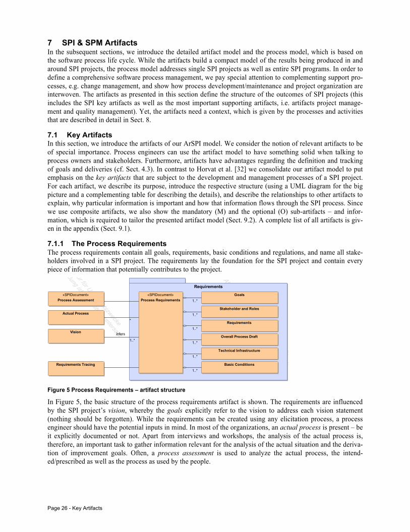
Page 26 - Key Artifacts
7 SPI & SPM Artifacts In the subsequent sections, we introduce the detailed artifact model and the process model, which is based on the software process life cycle. While the artifacts build a compact model of the results being produced in and around SPI projects, the process model addresses single SPI projects as well as entire SPI programs. In order to define a comprehensive software process management, we pay special attention to complementing support pro-cesses, e.g. change management, and show how process development/maintenance and project organization are interwoven. The artifacts as presented in this section define the structure of the outcomes of SPI projects (this includes the SPI key artifacts as well as the most important supporting artifacts, i.e. artifacts project manage-ment and quality management). Yet, the artifacts need a context, which is given by the processes and activities that are described in detail in Sect. 8.
7.1 Key Artifacts In this section, we introduce the artifacts of our ArSPI model. We consider the notion of relevant artifacts to be of special importance. Process engineers can use the artifact model to have something solid when talking to process owners and stakeholders. Furthermore, artifacts have advantages regarding the definition and tracking of goals and deliveries (cf. Sect. 4.3). In contrast to Horvat et al. [32] we consolidate our artifact model to put emphasis on the key artifacts that are subject to the development and management processes of a SPI project. For each artifact, we describe its purpose, introduce the respective structure (using a UML diagram for the big picture and a complementing table for describing the details), and describe the relationships to other artifacts to explain, why particular information is important and how that information flows through the SPI process. Since we use composite artifacts, we also show the mandatory (M) and the optional (O) sub-artifacts – and infor-mation, which is required to tailor the presented artifact model (Sect. 9.2). A complete list of all artifacts is giv-en in the appendix (Sect. 9.1).
7.1.1 The Process Requirements The process requirements contain all goals, requirements, basic conditions and regulations, and name all stake-holders involved in a SPI project. The requirements lay the foundation for the SPI project and contain every piece of information that potentially contributes to the project.
Figure 5 Process Requirements – artifact structure
In Figure 5, the basic structure of the process requirements artifact is shown. The requirements are influenced by the SPI project’s vision, whereby the goals explicitly refer to the vision to address each vision statement (nothing should be forgotten). While the requirements can be created using any elicitation process, a process engineer should have the potential inputs in mind. In most of the organizations, an actual process is present – be it explicitly documented or not. Apart from interviews and workshops, the analysis of the actual process is, therefore, an important task to gather information relevant for the analysis of the actual situation and the deriva-tion of improvement goals. Often, a process assessment is used to analyze the actual process, the intend-ed/prescribed as well as the process as used by the people.
MagicDraw UML, 1-1 /Users/kuhrmann/Documents/Research/CC-Processes/Publikationen/2013/IST (SPI)/Preparation/SPI-Blueprint/SPI-Blueprint.mdzip Requirements 11.07.2013 13:13:28
Akademische Version nur für Unterrichtszwecke, Kommerzielle Entwicklung ist strengstens untersagt
Akademische Version nur für Unterrichtszwecke
Kommerzielle Entwicklung ist strengstens untersagt
Akademische Version nur für Unterrichtszwecke
Kommerzielle Entwicklung ist strengstens untersagt
Akademische Version nur für Unterrichtszwecke
Kommerzielle Entwicklung ist strengstens untersagt
Akademische Version nur für Unterrichtszwecke
Kommerzielle Entwicklung ist strengstens untersagt
Akademische Version nur für Unterrichtszwecke
Kommerzielle Entwicklung ist strengstens untersagt
Akademische Version nur für Unterrichtszwecke
Kommerzielle Entwicklung ist strengstens untersagt
Akademische Version nur für Unterrichtszwecke
Kommerzielle Entwicklung ist strengstens untersagt
Akademische Version nur für Unterrichtszwecke
Kommerzielle Entwicklung ist strengstens untersagt
Akademische Version nur für Unterrichtszwecke
Kommerzielle Entwicklung ist strengstens untersagtRequirements
«SPIDocument»Process Requirements
Basic Conditions
Overall Process Draft
Requirements
Stakeholder and Roles
Technical Infrastructure
Goals«SPIDocument»Process Assessment
Requirements Tracing
Vision
Actual Process
1..*
1..*
1..*
1..*
1..*
1..*
infers
1..*
*
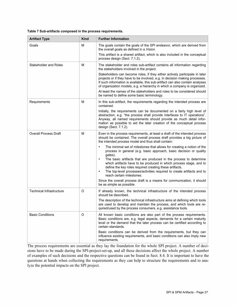
SPI & SPM Artifacts - Page 27
Table 7 Sub-artifacts composed in the process requirements.
Artifact Type Kind Further Information
Goals M The goals contain the goals of the SPI endeavor, which are derived from the overall goals as defined in a Vision. This artifact is a shared artifact, which is also included in the conceptual process design (Sect. 7.1.2).
Stakeholder and Roles M The stakeholder and roles sub-artifact contains all information regarding the stakeholders involved in the project. Stakeholders can become roles, if they either actively participate in later projects or if they have to be involved, e.g. in decision making processes. If such information is available, this sub-artifact can also contain analyses of organization models, e.g. a hierarchy in which a company is organized. At least the names of the stakeholders and roles to be considered should be named to define some basic terminology.
Requirements M In this sub-artifact, the requirements regarding the intended process are contained. Initially, the requirements can be documented on a fairly high level of abstraction, e.g. “the process shall provide interfaces to IT operations”. Anyway, all named requirements should provide as much detail infor-mation as possible to aid the later creation of the conceptual process design (Sect. 7.1.2).
Overall Process Draft M Even in the process requirements, at least a draft of the intended process should be contained. The overall process draft provides a big picture of the intended process model and thus shall contain: • The minimal set of milestones that allows for creating a notion of the
process in general (e.g. basic approach, basic decision or quality gates).
• The basic artifacts that are produced in the process to determine which artifacts have to be produced in which process stage, and to define the key roles required creating these artifacts.
• The top-level processes/activities required to create artifacts and to reach certain milestones.
Since the overall process draft is a means for communication, it should be as simple as possible.
Technical Infrastructure O If already known, the technical infrastructure of the intended process should be described. The description of the technical infrastructure aims at defining which tools are used to develop and maintain the process, and which tools are re-quired/used by the process consumers, e.g. assistance tools.
Basic Conditions O All known basic conditions are also part of the process requirements. Basic conditions are, e.g. legal aspects, demands for a certain maturity level or the demand that the later process can be certified according to certain standards. Basic conditions can be derived from the requirements, but they can influence existing requirements, and basic conditions can also imply new requirements.
The process requirements are essential as they lay the foundation for the whole SPI project. A number of deci-sions have to be made during the SPI-project-set-up, and all these decisions affect the whole project. A number of examples of such decisions and the respective questions can be found in Sect. 8.4. It is important to have the questions at hands when collecting the requirements as they can help to structure the requirements and to ana-lyze the potential impacts on the SPI project.
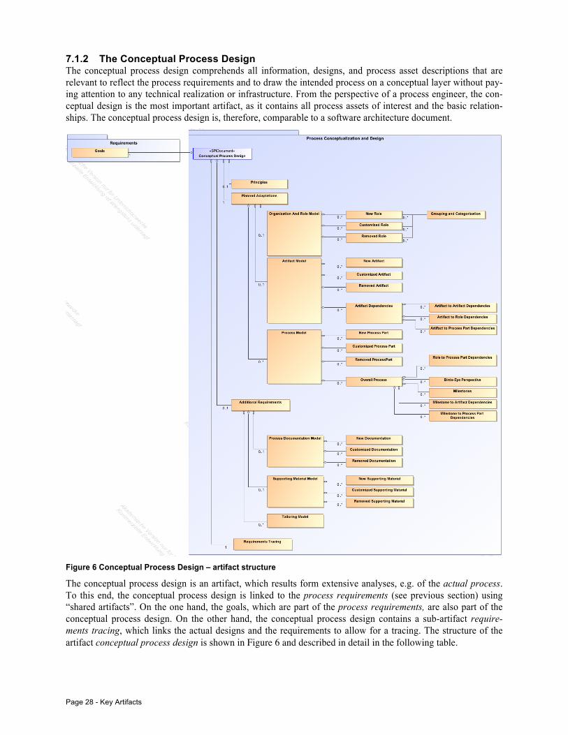
Page 28 - Key Artifacts
7.1.2 The Conceptual Process Design The conceptual process design comprehends all information, designs, and process asset descriptions that are relevant to reflect the process requirements and to draw the intended process on a conceptual layer without pay-ing attention to any technical realization or infrastructure. From the perspective of a process engineer, the con-ceptual design is the most important artifact, as it contains all process assets of interest and the basic relation-ships. The conceptual process design is, therefore, comparable to a software architecture document.
Figure 6 Conceptual Process Design – artifact structure
The conceptual process design is an artifact, which results form extensive analyses, e.g. of the actual process. To this end, the conceptual process design is linked to the process requirements (see previous section) using “shared artifacts”. On the one hand, the goals, which are part of the process requirements, are also part of the conceptual process design. On the other hand, the conceptual process design contains a sub-artifact require-ments tracing, which links the actual designs and the requirements to allow for a tracing. The structure of the artifact conceptual process design is shown in Figure 6 and described in detail in the following table.
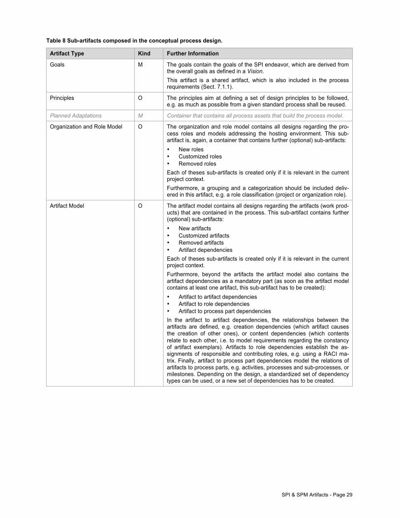
SPI & SPM Artifacts - Page 29
Table 8 Sub-artifacts composed in the conceptual process design.
Artifact Type Kind Further Information
Goals M The goals contain the goals of the SPI endeavor, which are derived from the overall goals as defined in a Vision. This artifact is a shared artifact, which is also included in the process requirements (Sect. 7.1.1).
Principles O The principles aim at defining a set of design principles to be followed, e.g. as much as possible from a given standard process shall be reused.
Planned Adaptations M Container that contains all process assets that build the process model.
Organization and Role Model O The organization and role model contains all designs regarding the pro-cess roles and models addressing the hosting environment. This sub-artifact is, again, a container that contains further (optional) sub-artifacts: • New roles • Customized roles • Removed roles Each of theses sub-artifacts is created only if it is relevant in the current project context. Furthermore, a grouping and a categorization should be included deliv-ered in this artifact, e.g. a role classification (project or organization role).
Artifact Model O The artifact model contains all designs regarding the artifacts (work prod-ucts) that are contained in the process. This sub-artifact contains further (optional) sub-artifacts: • New artifacts • Customized artifacts • Removed artifacts • Artifact dependencies Each of theses sub-artifacts is created only if it is relevant in the current project context. Furthermore, beyond the artifacts the artifact model also contains the artifact dependencies as a mandatory part (as soon as the artifact model contains at least one artifact, this sub-artifact has to be created): • Artifact to artifact dependencies • Artifact to role dependencies • Artifact to process part dependencies In the artifact to artifact dependencies, the relationships between the artifacts are defined, e.g. creation dependencies (which artifact causes the creation of other ones), or content dependencies (which contents relate to each other, i.e. to model requirements regarding the constancy of artifact exemplars). Artifacts to role dependencies establish the as-signments of responsible and contributing roles, e.g. using a RACI ma-trix. Finally, artifact to process part dependencies model the relations of artifacts to process parts, e.g. activities, processes and sub-processes, or milestones. Depending on the design, a standardized set of dependency types can be used, or a new set of dependencies has to be created.
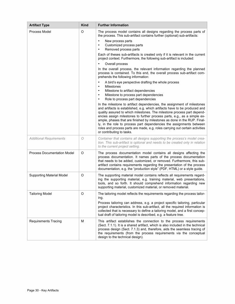
Page 30 - Key Artifacts
Artifact Type Kind Further Information
Process Model O The process model contains all designs regarding the process parts of the process. This sub-artifact contains further (optional) sub-artifacts: • New process parts • Customized process parts • Removed process parts Each of theses sub-artifacts is created only if it is relevant in the current project context. Furthermore, the following sub-artifact is included: • Overall process In the overall process, the relevant information regarding the planned process is contained. To this end, the overall process sub-artifact com-prehends the following information: • A bird’s eye perspective drafting the whole process • Milestones • Milestone to artifact dependencies • Milestone to process part dependencies • Role to process part dependencies In the milestone to artifact dependencies, the assignment of milestones and artifacts is established, e.g. which artifacts have to be produced and quality assured to which milestones. The milestone process part depend-encies assign milestones to further process parts, e.g., as a simple ex-ample, phases that are finished by milestones as done in the RUP. Final-ly, in the role to process part dependencies the assignments between roles and process parts are made, e.g. roles carrying out certain activities or contributing to tasks.
Additional Requirements O Container that contains all designs supporting the process’s model crea-tion. This sub-artifact is optional and needs to be created only in relation to the current project setting.
Process Documentation Model O The process documentation model contains all designs affecting the process documentation. It names parts of the process documentation that needs to be added, customized, or removed. Furthermore, this sub-artifact contains requirements regarding the presentation of the process documentation, e.g. the “production style” (PDF, HTML) or a style guide.
Supporting Material Model O The supporting material model contains reflects all requirements regard-ing the supporting material, e.g. training material, web presentations, tools, and so forth. It should comprehend information regarding new supporting material, customized material, or removed material.
Tailoring Model O The tailoring model reflects the requirements regarding the process tailor-ing. Process tailoring can address, e.g. a project specific tailoring, particular project characteristics. In this sub-artifact, all the required information is collected that is necessary to define a tailoring model, and a first concep-tual draft of tailoring model is described, e.g. a feature tree.
Requirements Tracing M This artifact establishes the connection to the process requirements (Sect. 7.1.1). It is a shared artifact, which is also included in the technical process design (Sect. 7.1.3) and, therefore, aids the seamless tracing of the requirements (from the process requirements via the conceptual design to the technical design).
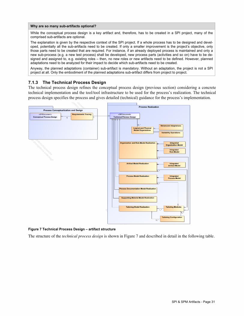
SPI & SPM Artifacts - Page 31
Why are so many sub-artifacts optional?
While the conceptual process design is a key artifact and, therefore, has to be created in a SPI project, many of the comprised sub-artifacts are optional. The explanation is given by the respective context of the SPI project. If a whole process has to be designed and devel-oped, potentially all the sub-artifacts need to be created. If only a smaller improvement is the project’s objective, only those parts need to be created that are required. For instance, if an already deployed process is maintained and only a new sub-process (e.g. a new test process) shall be developed, new process parts (activities and so on) have to be de-signed and assigned to, e.g. existing roles – then, no new roles or new artifacts need to be defined. However, planned adaptations need to be analyzed for their impact to decide which sub-artifacts need to be created. Anyway, the planned adaptations (container) sub-artifact is mandatory. Without an adaptation, the project is not a SPI project at all. Only the embodiment of the planned adaptations sub-artifact differs from project to project.
7.1.3 The Technical Process Design The technical process design refines the conceptual process design (previous section) considering a concrete technical implementation and the tool/tool infrastructure to be used for the process’s realization. The technical process design specifies the process and gives detailed (technical) guidance for the process’s implementation.
Figure 7 Technical Process Design – artifact structure
The structure of the technical process design is shown in Figure 7 and described in detail in the following table.
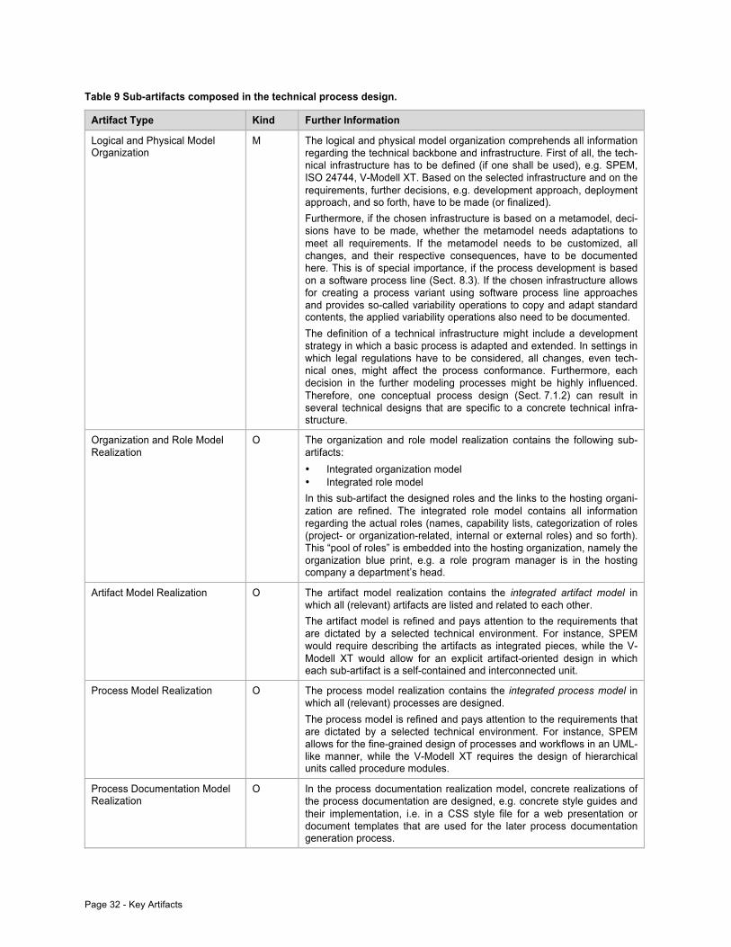
Page 32 - Key Artifacts
Table 9 Sub-artifacts composed in the technical process design.
Artifact Type Kind Further Information
Logical and Physical Model Organization
M The logical and physical model organization comprehends all information regarding the technical backbone and infrastructure. First of all, the tech-nical infrastructure has to be defined (if one shall be used), e.g. SPEM, ISO 24744, V-Modell XT. Based on the selected infrastructure and on the requirements, further decisions, e.g. development approach, deployment approach, and so forth, have to be made (or finalized). Furthermore, if the chosen infrastructure is based on a metamodel, deci-sions have to be made, whether the metamodel needs adaptations to meet all requirements. If the metamodel needs to be customized, all changes, and their respective consequences, have to be documented here. This is of special importance, if the process development is based on a software process line (Sect. 8.3). If the chosen infrastructure allows for creating a process variant using software process line approaches and provides so-called variability operations to copy and adapt standard contents, the applied variability operations also need to be documented. The definition of a technical infrastructure might include a development strategy in which a basic process is adapted and extended. In settings in which legal regulations have to be considered, all changes, even tech-nical ones, might affect the process conformance. Furthermore, each decision in the further modeling processes might be highly influenced. Therefore, one conceptual process design (Sect. 7.1.2) can result in several technical designs that are specific to a concrete technical infra-structure.
Organization and Role Model Realization
O The organization and role model realization contains the following sub-artifacts: • Integrated organization model • Integrated role model In this sub-artifact the designed roles and the links to the hosting organi-zation are refined. The integrated role model contains all information regarding the actual roles (names, capability lists, categorization of roles (project- or organization-related, internal or external roles) and so forth). This “pool of roles” is embedded into the hosting organization, namely the organization blue print, e.g. a role program manager is in the hosting company a department’s head.
Artifact Model Realization O The artifact model realization contains the integrated artifact model in which all (relevant) artifacts are listed and related to each other. The artifact model is refined and pays attention to the requirements that are dictated by a selected technical environment. For instance, SPEM would require describing the artifacts as integrated pieces, while the V-Modell XT would allow for an explicit artifact-oriented design in which each sub-artifact is a self-contained and interconnected unit.
Process Model Realization O The process model realization contains the integrated process model in which all (relevant) processes are designed. The process model is refined and pays attention to the requirements that are dictated by a selected technical environment. For instance, SPEM allows for the fine-grained design of processes and workflows in an UML-like manner, while the V-Modell XT requires the design of hierarchical units called procedure modules.
Process Documentation Model Realization
O In the process documentation realization model, concrete realizations of the process documentation are designed, e.g. concrete style guides and their implementation, i.e. in a CSS style file for a web presentation or document templates that are used for the later process documentation generation process.
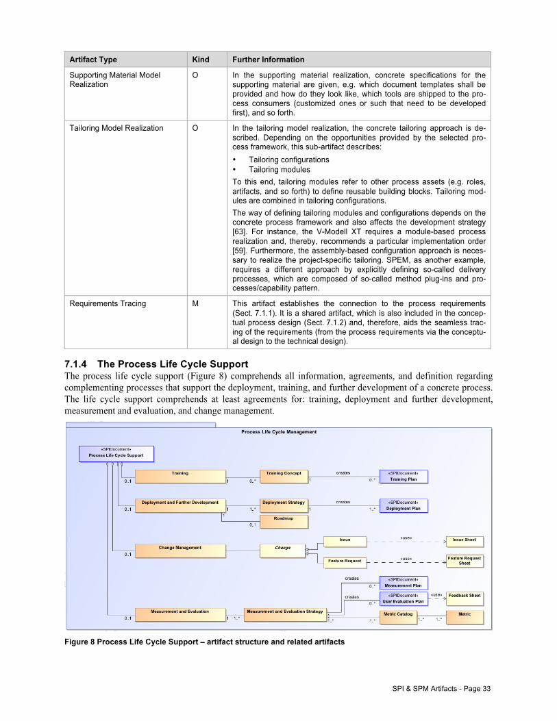
SPI & SPM Artifacts - Page 33
Artifact Type Kind Further Information
Supporting Material Model Realization
O In the supporting material realization, concrete specifications for the supporting material are given, e.g. which document templates shall be provided and how do they look like, which tools are shipped to the pro-cess consumers (customized ones or such that need to be developed first), and so forth.
Tailoring Model Realization O In the tailoring model realization, the concrete tailoring approach is de-scribed. Depending on the opportunities provided by the selected pro-cess framework, this sub-artifact describes: • Tailoring configurations • Tailoring modules To this end, tailoring modules refer to other process assets (e.g. roles, artifacts, and so forth) to define reusable building blocks. Tailoring mod-ules are combined in tailoring configurations. The way of defining tailoring modules and configurations depends on the concrete process framework and also affects the development strategy [63]. For instance, the V-Modell XT requires a module-based process realization and, thereby, recommends a particular implementation order [59]. Furthermore, the assembly-based configuration approach is neces-sary to realize the project-specific tailoring. SPEM, as another example, requires a different approach by explicitly defining so-called delivery processes, which are composed of so-called method plug-ins and pro-cesses/capability pattern.
Requirements Tracing M This artifact establishes the connection to the process requirements (Sect. 7.1.1). It is a shared artifact, which is also included in the concep-tual process design (Sect. 7.1.2) and, therefore, aids the seamless trac-ing of the requirements (from the process requirements via the conceptu-al design to the technical design).
7.1.4 The Process Life Cycle Support The process life cycle support (Figure 8) comprehends all information, agreements, and definition regarding complementing processes that support the deployment, training, and further development of a concrete process. The life cycle support comprehends at least agreements for: training, deployment and further development, measurement and evaluation, and change management.
Figure 8 Process Life Cycle Support – artifact structure and related artifacts
Page 34 - Key Artifacts
The process life cycle support is the artifact comprising all definitions and agreements on methods and process-es that are specific for one particular process, which is the subject of a SPI project. For each considered process or process variant, a specific life cycle support should be provided. In the context of a software process line, the variant-specific life cycle support documentation should be in line with an overall documentation, which is defined for the entire process line or, at least, for the process line’s reference process.
In the process life cycle support, at least definitions have to be made regarding measurement and evaluation, change management, deployment and further development, and training. For each of the named areas, strategies have to be worked out, which serve as the basis for respective planning, e.g. training plans, deployment/release plans. Since these activities complement the process’s development and deployment, and consume resources, e.g. personnel to be trained, these activities have to be carefully planned and aligned with the company’s day-to-day business.
Two aspects are of special importance: in the measurement strategy, a metric catalog has to be developed. The metrics can be defined, e.g. using a company-wide catalog to allow for a seamless measurement strategy. Se-cond, for each process a long-term strategy – a roadmap – needs to be defined. The roadmap is necessary to outline the long-term development of a process, which feature and capabilities will be available, and when. Therefore, a roadmap, on the one hand, forces the management to commit on a SPI endeavor and to provide funding and support and, on the other hand, a roadmap provides security for the projects and project teams. Table 10 Sub-artifacts composed in the process life cycle support.
Artifact Type Kind Further Information
Training O Planning regarding the training contains all information and definitions on the required trainings for the process stakeholders. To this end, training concepts are created, depending on the project setting, multiple training concepts can be developed, e.g. one concept per stakeholder group. The definitions regarding the trainings affect the training plan and, finally, result in the creation of respective training material.
Deployment and Further Development
O Deployment and further development address two aspects: 1. At first, the process has to be packaged and shipped to the consum-
ers, either for testing or for using the process. Definitions regarding the packaging and deployment result in a deployment plan (a re-lease plan) in which releases and a respective schedule are con-tained.
2. Second, if process development is a long-term endeavor, a roadmap has to be created in which the long-term goals are defined. The im-portance of a roadmap should not be underestimated. For instance, in the development of the reference model 1-RM (cf. Table 1) a roadmap was developed rather late. Therefore, process consumers complained that they had no idea which features will be in the next release and when will the next version be released.
Change Management O The change management process is of special importance for a software process, especially if the process under consideration is part of a soft-ware process line (SPL). Basically, two kinds of changes have to be considered: an issue and a feature request. • An issue is a process-related change that is caused by problems
that occur during project operation, e.g. a defined practice turns out inadequate and needed to be replaced in every project.
• A feature request is a change that represents a new requirement for a process, e.g. to fill a gap that becomes obvious in several projects.
The change management is crucial as a change might affect multiple process assets, and dealing with a particular change can cause substan-tial effort, especially if the change is global in terms of affecting not only a single reference model or variant, but also all variants.
SPI & SPM Artifacts - Page 35
Artifact Type Kind Further Information
Measurement and Evaluation O In order to determine the feasibility of a software process, a measure-ment and evaluation strategy has to be defined. To this end, a set of metrics has to be defined, which are comprised into metric catalogs. Depending on the concrete setting, multiple metric catalogs can be de-fined for a SPI project. The measurement and evaluation strategy results in – at least – a measurement plan and a user evaluation plan. • The measurement plan aims at determining the process perfor-
mance in general, e.g. quality of resulting products, schedule adher-ence. To this end, the measurement plan addresses the process engineers to determine the effectiveness of improvements.
• The user evaluation plan aims at determining user satisfaction and to get feedback from the process consumers, e.g. does the process meet the expectations, does the process provide sufficient support.
To this end, the outcomes of the measurement and evaluation provide important information to drive the further development of a process vari-ant or the entire process line.
Don’t forget…
When defining the measurement plan, it is important to recognize several points: • “Don’t measure a project to death!” The measurement plan should be defined in order to meet the project goals. To
this end, the goals have to be clearly defined in the process requirements (Sect. 7.1.1). • Only KPIs that are relevant in order to determine the improvements in relation to the goals should be measured.
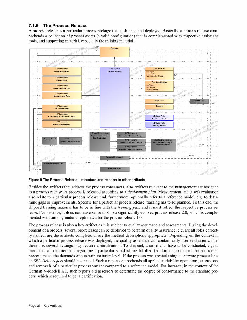
Page 36 - Key Artifacts
7.1.5 The Process Release A process release is a particular process package that is shipped and deployed. Basically, a process release com-prehends a collection of process assets (a valid configuration) that is complemented with respective assistance tools, and supporting material, especially the training material.
Figure 9 The Process Release – structure and relation to other artifacts
Besides the artifacts that address the process consumers, also artifacts relevant to the management are assigned to a process release. A process is released according to a deployment plan. Measurement and (user) evaluation also relate to a particular process release and, furthermore, optionally refer to a reference model, e.g. to deter-mine gaps or improvements. Specific for a particular process release, training has to be planned. To this end, the shipped training material has to be in line with the training plan and it must reflect the respective process re-lease. For instance, it does not make sense to ship a significantly evolved process release 2.0, which is comple-mented with training material optimized for the process release 1.0.
The process release is also a key artifact as it is subject to quality assurance and assessments. During the devel-opment of a process, several pre-releases can be deployed to perform quality assurance, e.g. are all roles correct-ly named, are the artifacts complete, or are the method descriptions appropriate. Depending on the context in which a particular process release was deployed, the quality assurance can contain early user evaluations. Fur-thermore, several settings may require a certification. To this end, assessments have to be conducted, e.g. to proof that all requirements regarding a particular standard are fulfilled (conformance) or that the considered process meets the demands of a certain maturity level. If the process was created using a software process line, an SPL-Delta report should be created. Such a report comprehends all applied variability operations, extensions, and removals of a particular process variant compared to a reference model. For instance, in the context of the German V-Modell XT, such reports aid assessors to determine the degree of conformance to the standard pro-cess, which is required to get a certification.
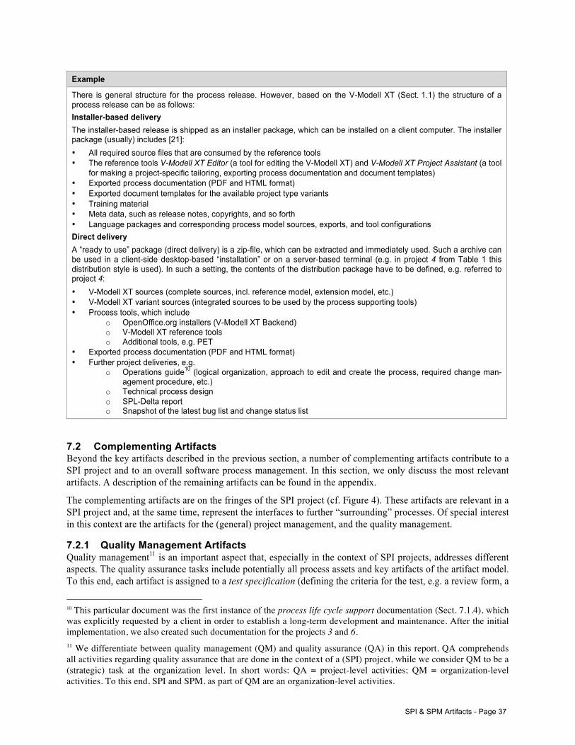
SPI & SPM Artifacts - Page 37
Example
There is general structure for the process release. However, based on the V-Modell XT (Sect. 1.1) the structure of a process release can be as follows: Installer-based delivery The installer-based release is shipped as an installer package, which can be installed on a client computer. The installer package (usually) includes [21]: • All required source files that are consumed by the reference tools • The reference tools V-Modell XT Editor (a tool for editing the V-Modell XT) and V-Modell XT Project Assistant (a tool
for making a project-specific tailoring, exporting process documentation and document templates) • Exported process documentation (PDF and HTML format) • Exported document templates for the available project type variants • Training material • Meta data, such as release notes, copyrights, and so forth • Language packages and corresponding process model sources, exports, and tool configurations Direct delivery A “ready to use” package (direct delivery) is a zip-file, which can be extracted and immediately used. Such a archive can be used in a client-side desktop-based “installation” or on a server-based terminal (e.g. in project 4 from Table 1 this distribution style is used). In such a setting, the contents of the distribution package have to be defined, e.g. referred to project 4: • V-Modell XT sources (complete sources, incl. reference model, extension model, etc.) • V-Modell XT variant sources (integrated sources to be used by the process supporting tools) • Process tools, which include
o OpenOffice.org installers (V-Modell XT Backend) o V-Modell XT reference tools o Additional tools, e.g. PET
• Exported process documentation (PDF and HTML format) • Further project deliveries, e.g.
o Operations guide10 (logical organization, approach to edit and create the process, required change man-agement procedure, etc.)
o Technical process design o SPL-Delta report o Snapshot of the latest bug list and change status list
7.2 Complementing Artifacts Beyond the key artifacts described in the previous section, a number of complementing artifacts contribute to a SPI project and to an overall software process management. In this section, we only discuss the most relevant artifacts. A description of the remaining artifacts can be found in the appendix.
The complementing artifacts are on the fringes of the SPI project (cf. Figure 4). These artifacts are relevant in a SPI project and, at the same time, represent the interfaces to further “surrounding” processes. Of special interest in this context are the artifacts for the (general) project management, and the quality management.
7.2.1 Quality Management Artifacts Quality management11 is an important aspect that, especially in the context of SPI projects, addresses different aspects. The quality assurance tasks include potentially all process assets and key artifacts of the artifact model. To this end, each artifact is assigned to a test specification (defining the criteria for the test, e.g. a review form, a
10 This particular document was the first instance of the process life cycle support documentation (Sect. 7.1.4), which was explicitly requested by a client in order to establish a long-term development and maintenance. After the initial implementation, we also created such documentation for the projects 3 and 6. 11 We differentiate between quality management (QM) and quality assurance (QA) in this report. QA comprehends all activities regarding quality assurance that are done in the context of a (SPI) project, while we consider QM to be a (strategic) task at the organization level. In short words: QA = project-level activities; QM = organization-level activities. To this end, SPI and SPM, as part of QM are an organization-level activities.
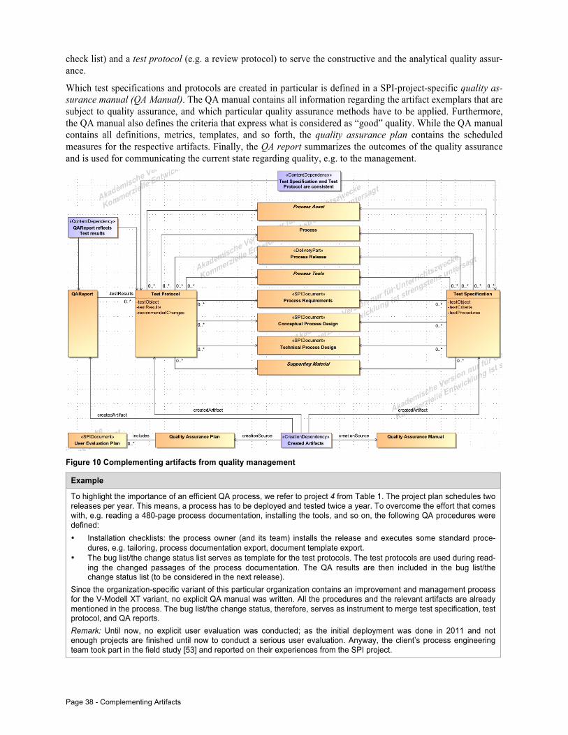
Page 38 - Complementing Artifacts
check list) and a test protocol (e.g. a review protocol) to serve the constructive and the analytical quality assur-ance.
Which test specifications and protocols are created in particular is defined in a SPI-project-specific quality as-surance manual (QA Manual). The QA manual contains all information regarding the artifact exemplars that are subject to quality assurance, and which particular quality assurance methods have to be applied. Furthermore, the QA manual also defines the criteria that express what is considered as “good” quality. While the QA manual contains all definitions, metrics, templates, and so forth, the quality assurance plan contains the scheduled measures for the respective artifacts. Finally, the QA report summarizes the outcomes of the quality assurance and is used for communicating the current state regarding quality, e.g. to the management.
Figure 10 Complementing artifacts from quality management
Example
To highlight the importance of an efficient QA process, we refer to project 4 from Table 1. The project plan schedules two releases per year. This means, a process has to be deployed and tested twice a year. To overcome the effort that comes with, e.g. reading a 480-page process documentation, installing the tools, and so on, the following QA procedures were defined: • Installation checklists: the process owner (and its team) installs the release and executes some standard proce-
dures, e.g. tailoring, process documentation export, document template export. • The bug list/the change status list serves as template for the test protocols. The test protocols are used during read-
ing the changed passages of the process documentation. The QA results are then included in the bug list/the change status list (to be considered in the next release).
Since the organization-specific variant of this particular organization contains an improvement and management process for the V-Modell XT variant, no explicit QA manual was written. All the procedures and the relevant artifacts are already mentioned in the process. The bug list/the change status, therefore, serves as instrument to merge test specification, test protocol, and QA reports. Remark: Until now, no explicit user evaluation was conducted; as the initial deployment was done in 2011 and not enough projects are finished until now to conduct a serious user evaluation. Anyway, the client’s process engineering team took part in the field study [53] and reported on their experiences from the SPI project.
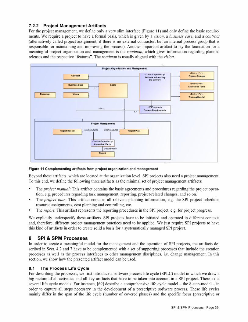
SPI & SPM Processes - Page 39
7.2.2 Project Management Artifacts For the project management, we define only a very slim interface (Figure 11) and only define the basic require-ments. We require a project to have a formal basis, which is given by a vision, a business case, and a contract (alternatively called project assignment, if there is no external contractor, but an internal process group that is responsible for maintaining and improving the process). Another important artifact to lay the foundation for a meaningful project organization and management is the roadmap, which gives information regarding planned releases and the respective “features”. The roadmap is usually aligned with the vision.
Figure 11 Complementing artifacts from project organization and management
Beyond these artifacts, which are located at the organization level, SPI projects also need a project management. To this end, we define the following three artifacts as the minimal set of project management artifacts:
• The project manual: This artifact contains the basic agreements and procedures regarding the project opera-tion, e.g. procedures regarding task management, reporting, project-related changes, and so on.
• The project plan: This artifact contains all relevant planning information, e.g. the SPI project schedule, resource assignments, cost planning and controlling, etc.
• The report: This artifact represents the reporting procedures in the SPI project, e.g. for project progress.
We explicitly underspecify these artifacts. SPI projects have to be initiated and operated in different contexts and, therefore, different project management practices need to be applied. We just require SPI projects to have this kind of artifacts in order to create solid a basis for a systematically managed SPI project.
8 SPI & SPM Processes In order to create a meaningful model for the management and the operation of SPI projects, the artifacts de-scribed in Sect. 4.2 and 7 have to be complemented with a set of supporting processes that include the creation processes as well as the process interfaces to other management disciplines, i.e. change management. In this section, we show how the presented artifact model can be used.
8.1 The Process Life Cycle For describing the processes, we first introduce a software process life cycle (SPLC) model in which we draw a big picture of all activities and all key artifacts that have to be taken into account in a SPI project. There exist several life cycle models. For instance, [69] describe a comprehensive life cycle model – the 8-step-model – in order to capture all steps necessary in the development of a prescriptive software process. These life cycles mainly differ in the span of the life cycle (number of covered phases) and the specific focus (prescriptive or
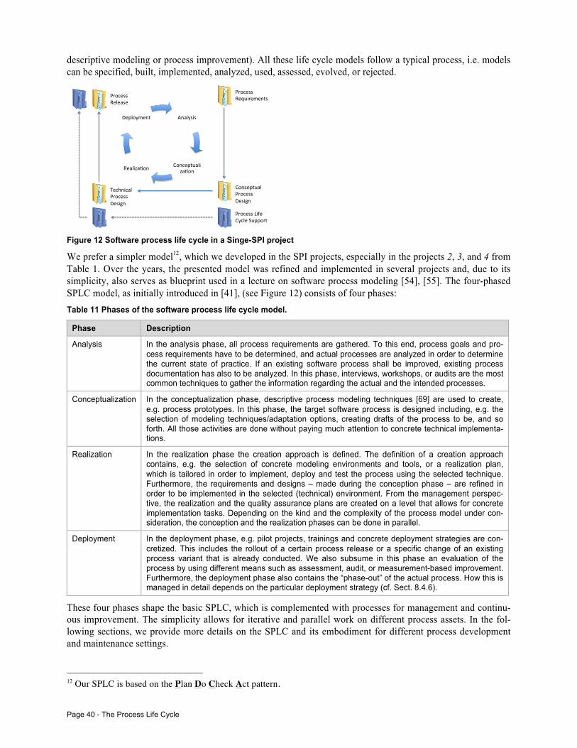
Page 40 - The Process Life Cycle
descriptive modeling or process improvement). All these life cycle models follow a typical process, i.e. models can be specified, built, implemented, analyzed, used, assessed, evolved, or rejected.
Figure 12 Software process life cycle in a Singe-SPI project
We prefer a simpler model12, which we developed in the SPI projects, especially in the projects 2, 3, and 4 from Table 1. Over the years, the presented model was refined and implemented in several projects and, due to its simplicity, also serves as blueprint used in a lecture on software process modeling [54], [55]. The four-phased SPLC model, as initially introduced in [41], (see Figure 12) consists of four phases: Table 11 Phases of the software process life cycle model.
Phase Description
Analysis In the analysis phase, all process requirements are gathered. To this end, process goals and pro-cess requirements have to be determined, and actual processes are analyzed in order to determine the current state of practice. If an existing software process shall be improved, existing process documentation has also to be analyzed. In this phase, interviews, workshops, or audits are the most common techniques to gather the information regarding the actual and the intended processes.
Conceptualization In the conceptualization phase, descriptive process modeling techniques [69] are used to create, e.g. process prototypes. In this phase, the target software process is designed including, e.g. the selection of modeling techniques/adaptation options, creating drafts of the process to be, and so forth. All those activities are done without paying much attention to concrete technical implementa-tions.
Realization In the realization phase the creation approach is defined. The definition of a creation approach contains, e.g. the selection of concrete modeling environments and tools, or a realization plan, which is tailored in order to implement, deploy and test the process using the selected technique. Furthermore, the requirements and designs – made during the conception phase – are refined in order to be implemented in the selected (technical) environment. From the management perspec-tive, the realization and the quality assurance plans are created on a level that allows for concrete implementation tasks. Depending on the kind and the complexity of the process model under con-sideration, the conception and the realization phases can be done in parallel.
Deployment In the deployment phase, e.g. pilot projects, trainings and concrete deployment strategies are con-cretized. This includes the rollout of a certain process release or a specific change of an existing process variant that is already conducted. We also subsume in this phase an evaluation of the process by using different means such as assessment, audit, or measurement-based improvement. Furthermore, the deployment phase also contains the “phase-out” of the actual process. How this is managed in detail depends on the particular deployment strategy (cf. Sect. 8.4.6).
These four phases shape the basic SPLC, which is complemented with processes for management and continu-ous improvement. The simplicity allows for iterative and parallel work on different process assets. In the fol-lowing sections, we provide more details on the SPLC and its embodiment for different process development and maintenance settings.
12 Our SPLC is based on the Plan Do Check Act pattern.
Analysis(
Conceptualiza1on(Realiza1on(
Deployment(
Process(Requirements(
Conceptual(Process(Design(
Technical(Process(Design(
Process(Life(Cycle(Support(
Process(Release(
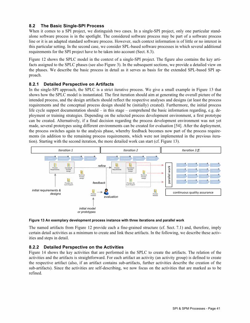
SPI & SPM Processes - Page 41
8.2 The Basic Single-SPI Process When it comes to a SPI project, we distinguish two cases. In a single-SPI project, only one particular stand-alone software process is in the spotlight. The considered software process may be part of a software process line or it is an adapted standard software process. However, such context information is of little or no interest in this particular setting. In the second case, we consider SPL-based software processes in which several additional requirements for the SPI project have to be taken into account (Sect. 8.3).
Figure 12 shows the SPLC model in the context of a single-SPI project. The figure also contains the key arti-facts assigned to the SPLC phases (see also Figure 3). In the subsequent sections, we provide a detailed view on the phases. We describe the basic process in detail as it serves as basis for the extended SPL-based SPI ap-proach.
8.2.1 Detailed Perspective on Artifacts In the single-SPI approach, the SPLC is a strict iterative process. We give a small example in Figure 13 that shows how the SPLC model is instantiated. The first iteration should aim at generating the overall picture of the intended process, and the design artifacts should reflect the respective analyses and designs (at least the process requirements and the conceptual process design should be (initially) created). Furthermore, the initial process life cycle support documentation should – in this stage – comprehend the basic information regarding, e.g. de-ployment or training strategies. Depending on the selected process development environment, a first prototype can be created. Alternatively, if a final decision regarding the process development environment was not yet made, several prototypes using different environments can be created for evaluation [54]. After the deployment, the process switches again to the analysis phase, whereby feedback becomes now part of the process require-ments (in addition to the remaining process requirements, which were not implemented in the previous itera-tion). Starting with the second iteration, the more detailed work can start (cf. Figure 13).
Figure 13 An exemplary development process instance with three iterations and parallel work
The named artifacts from Figure 12 provide each a fine-grained structure (cf. Sect. 7.1) and, therefore, imply certain detail activities as a minimum to create and link these artifacts. In the following, we describe these activ-ities and steps in detail.
8.2.2 Detailed Perspective on the Activities Figure 14 shows the key activities that are performed in the SPLC to create the artifacts. The relation of the activities and the artifacts is straightforward. For each artifact an activity (an activity group) is defined to create the respective artifact (also, if an artifact contains sub-artifacts, further activities describe the creation of the sub-artifacts). Since the activities are self-describing, we now focus on the activities that are marked as to be refined.
Analysis Conceptualization Realization Deployment
Process Requirements
Conceptual Process Design
Technical Process Design
Process Life Cycle Support
Process Release
Analysis Conceptualization Realization Deployment
Process Requirements
Conceptual Process Design
Technical Process Design
Process Life Cycle Support
Process Release
initial requirements & designs
initial model or prototypes
evaluation
feedback
refine parallel&w
ork& Analysis Conceptualization Realization Deployment
Analysis Conceptualization Realization Deployment
Analysis Conceptualization Realization Deployment
Analysis Conceptualization Realization Deployment
con,nuous&quality&assurance&
Itera&on)1) Itera&on)2) Itera&on)3)ff.)
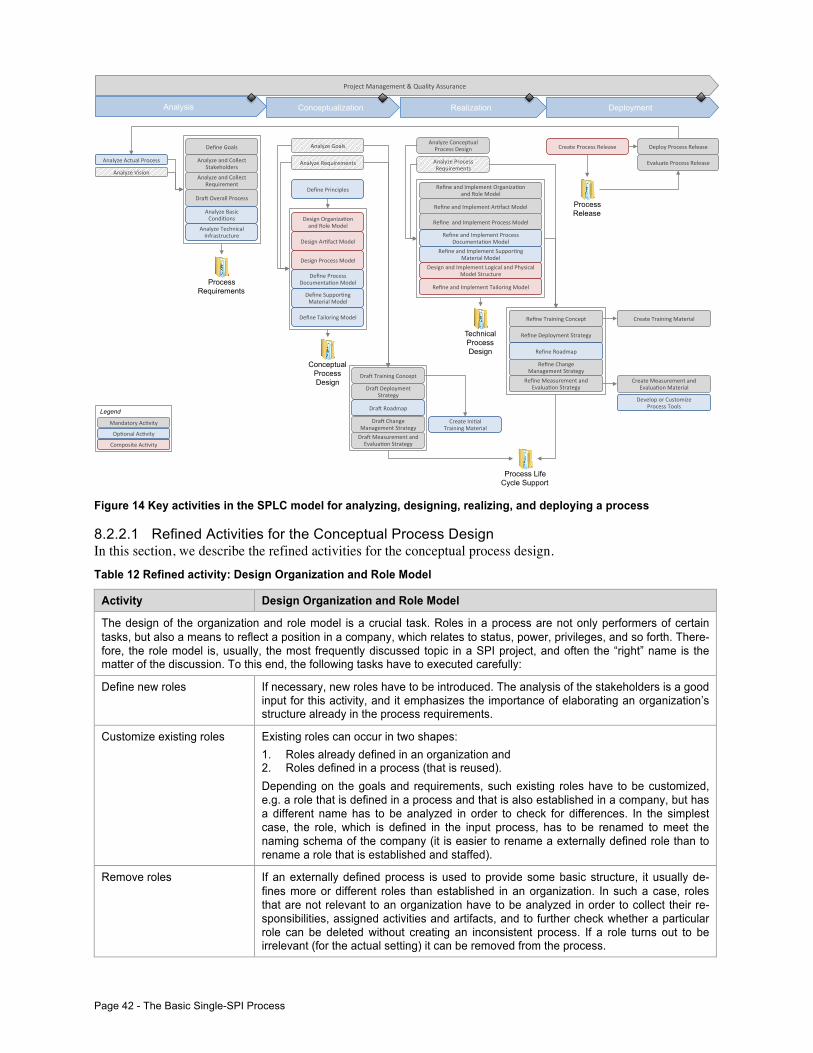
Page 42 - The Basic Single-SPI Process
Figure 14 Key activities in the SPLC model for analyzing, designing, realizing, and deploying a process
8.2.2.1 Refined Activities for the Conceptual Process Design In this section, we describe the refined activities for the conceptual process design. Table 12 Refined activity: Design Organization and Role Model
Activity Design Organization and Role Model
The design of the organization and role model is a crucial task. Roles in a process are not only performers of certain tasks, but also a means to reflect a position in a company, which relates to status, power, privileges, and so forth. There-fore, the role model is, usually, the most frequently discussed topic in a SPI project, and often the “right” name is the matter of the discussion. To this end, the following tasks have to executed carefully:
Define new roles If necessary, new roles have to be introduced. The analysis of the stakeholders is a good input for this activity, and it emphasizes the importance of elaborating an organization’s structure already in the process requirements.
Customize existing roles Existing roles can occur in two shapes: 1. Roles already defined in an organization and 2. Roles defined in a process (that is reused). Depending on the goals and requirements, such existing roles have to be customized, e.g. a role that is defined in a process and that is also established in a company, but has a different name has to be analyzed in order to check for differences. In the simplest case, the role, which is defined in the input process, has to be renamed to meet the naming schema of the company (it is easier to rename a externally defined role than to rename a role that is established and staffed).
Remove roles If an externally defined process is used to provide some basic structure, it usually de-fines more or different roles than established in an organization. In such a case, roles that are not relevant to an organization have to be analyzed in order to collect their re-sponsibilities, assigned activities and artifacts, and to further check whether a particular role can be deleted without creating an inconsistent process. If a role turns out to be irrelevant (for the actual setting) it can be removed from the process.
Project(Management(&(Quality(Assurance(
Analyze(Vision(
Analyze(Actual(Process(
Define(Goals(
Analyze(and(Collect(Stakeholders(
Analyze(and(Collect(Requirement(
DraB(Overall(Process(
Analyze(Basic(CondiFons(
Analyze(Technical(Infrastructure(
Analyze(Goals(
Analyze(Requirements(
Define(Principles(
Design(OrganizaFon(and(Role(Model(
Design(ArFfact(Model(
Design(Process(Model(
Define(Process(DocumentaFon(Model(
Define(SupporFng(Material(Model((
Define(Tailoring(Model(
DraB(Training(Concept(
DraB(Deployment(Strategy(
DraB(Roadmap(
DraB(Change(Management(Strategy(DraB(Measurement(and(EvaluaFon(Strategy(
Create(IniFal((Training(Material(
Analysis Conceptualization Realization Deployment
Process Requirements
Conceptual Process Design
Technical Process Design
Process Release
Process Life Cycle Support
Analyze(Conceptual((Process(Design(
Analyze(Process(Requirements(
Refine(and(Implement(OrganizaFon((and(Role(Model(
Refine(and(Implement(ArFfact(Model(
Refine((and(Implement(Process(Model(
Refine(and(Implement(Process(DocumentaFon(Model(
Refine(and(Implement(SupporFng((Material(Model(
Design(and(Implement(Logical(and(Physical(Model(Structure(
Refine(and(Implement(Tailoring(Model(
Refine(Training(Concept(
Refine(Deployment(Strategy(
Refine(Roadmap(
Refine(Change((Management(Strategy(
Refine(Measurement(and(EvaluaFon(Strategy(
Develop(or(Customize((Process(Tools(
Create(Training(Material(
Create(Measurement(and(EvaluaFon(Material(
Create(Process(Release( Deploy(Process(Release(
Evaluate(Process(Release(
Mandatory(AcFvity(
OpFonal(AcFvity(
Composite(AcFvity(
Legend
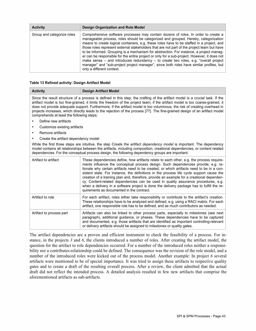
SPI & SPM Processes - Page 43
Activity Design Organization and Role Model
Group and categorize roles Comprehensive software processes may contain dozens of roles. In order to create a manageable process, roles should be categorized and grouped. Hereby, categorization means to create logical containers, e.g. these roles have to be staffed in a project, and those roles represent external stakeholders that are not part of the project team but have to be informed. Grouping is a mechanism for abstraction. For instance, a project manag-er can be responsible for the entire project or only for a sub-project. However, it does not make sense – and introduces redundancy – to create two roles, e.g. “overall project manager” and “sub-project project manager”, since both roles have similar profiles, but only a different context.
Table 13 Refined activity: Design Artifact Model
Activity Design Artifact Model
Since the result structure of a process is defined in this step, the crafting of the artifact model is a crucial task. If the artifact model is too fine-grained, it limits the freedom of the project team; if the artifact model is too coarse-grained, it does not provide adequate support. Furthermore, if the artifact model is too voluminous, the risk of creating overhead in projects increases, which directly leads to the rejection of the process [77]. The fine-grained design of an artifact model comprehends at least the following steps: • Define new artifacts • Customize existing artifacts • Remove artifacts • Create the artifact dependency model While the first three steps are intuitive, the step Create the artifact dependency model is important. The dependency model contains all relationships between the artifacts, including composition, creational dependencies, or content related dependencies. For the conceptual process design, the following dependency groups are important:
Artifact to artifact These dependencies define, how artifacts relate to each other, e.g. the process require-ments influence the conceptual process design. Such dependencies provide, e.g. ra-tionale why certain artifacts need to be created, or which artifacts need to be in a con-sistent state. For instance, the definitions in the process life cycle support cause the creation of a training plan and, therefore, provide an example for a creational dependen-cy. Content-related dependencies can be used in quality assurance procedures, e.g. when a delivery in a software project is done the delivery package has to fulfill the re-quirements as documented in the contract.
Artifact to role For each artifact, roles either take responsibility or contribute to the artifact’s creation. These relationships have to be analyzed and defined, e.g. using a RACI matrix. For each artifact, one responsible role has to be defined, and as much contributors as needed.
Artifact to process part Artifacts can also be linked to other process parts, especially to milestones (see next paragraph), additional guidance, or phases. These dependencies have to be captured and documented, e.g. those artifacts that are identified as important controlling-relevant or delivery artifacts should be assigned to milestones or quality gates.
The artifact dependencies are a proven and efficient instrument to check the feasibility of a process. For in-stance, in the projects 3 and 6, the clients introduced a number of roles. After creating the artifact model, the question for the artifact to role dependencies occurred. For a number of the introduced roles neither a responsi-bility nor a contributes-relationship could be defined. The consequence was the revision of the role model, and a number of the introduced roles were kicked out of the process model. Another example: In project 6 several artifacts were mentioned to be of special importance. It was tried to assign these artifacts to respective quality gates and to create a draft of the resulting overall process. After a review, the client admitted that the actual draft did not reflect the intended process. A detailed analysis resulted in few new artifacts that comprise the aforementioned artifacts as sub-artifacts.
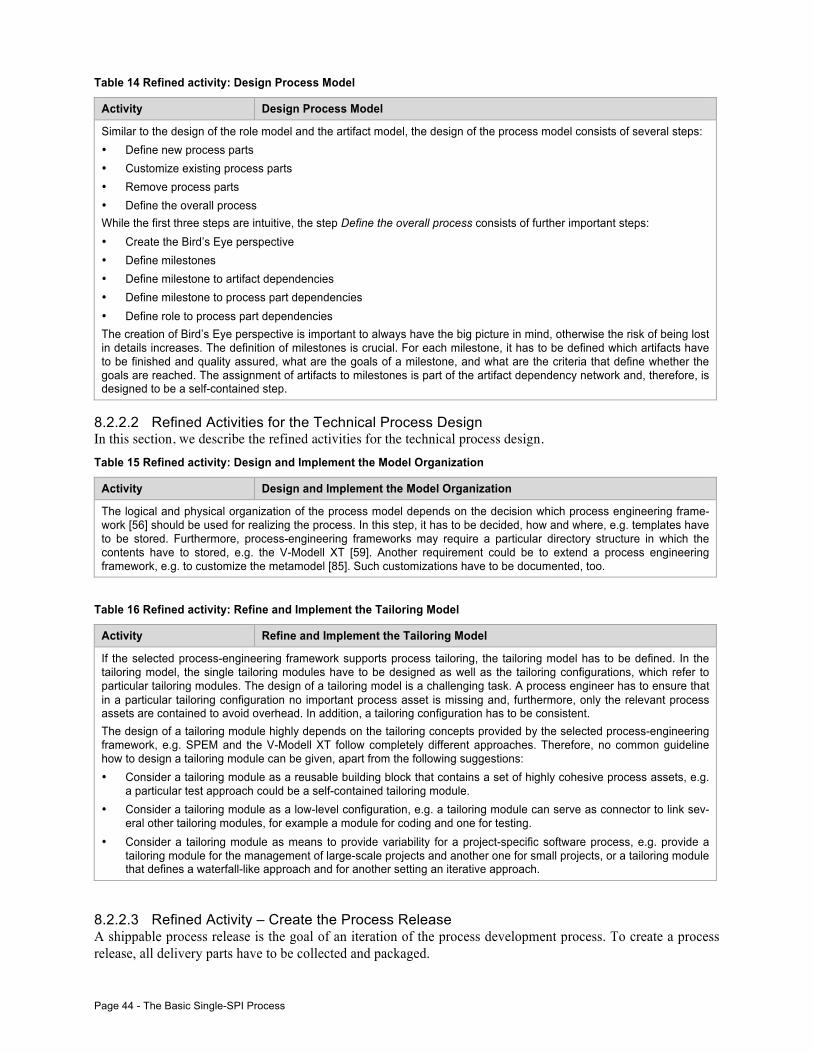
Page 44 - The Basic Single-SPI Process
Table 14 Refined activity: Design Process Model
Activity Design Process Model
Similar to the design of the role model and the artifact model, the design of the process model consists of several steps: • Define new process parts • Customize existing process parts • Remove process parts • Define the overall process While the first three steps are intuitive, the step Define the overall process consists of further important steps: • Create the Bird’s Eye perspective • Define milestones • Define milestone to artifact dependencies • Define milestone to process part dependencies • Define role to process part dependencies The creation of Bird’s Eye perspective is important to always have the big picture in mind, otherwise the risk of being lost in details increases. The definition of milestones is crucial. For each milestone, it has to be defined which artifacts have to be finished and quality assured, what are the goals of a milestone, and what are the criteria that define whether the goals are reached. The assignment of artifacts to milestones is part of the artifact dependency network and, therefore, is designed to be a self-contained step.
8.2.2.2 Refined Activities for the Technical Process Design In this section, we describe the refined activities for the technical process design. Table 15 Refined activity: Design and Implement the Model Organization
Activity Design and Implement the Model Organization
The logical and physical organization of the process model depends on the decision which process engineering frame-work [56] should be used for realizing the process. In this step, it has to be decided, how and where, e.g. templates have to be stored. Furthermore, process-engineering frameworks may require a particular directory structure in which the contents have to stored, e.g. the V-Modell XT [59]. Another requirement could be to extend a process engineering framework, e.g. to customize the metamodel [85]. Such customizations have to be documented, too.
Table 16 Refined activity: Refine and Implement the Tailoring Model
Activity Refine and Implement the Tailoring Model
If the selected process-engineering framework supports process tailoring, the tailoring model has to be defined. In the tailoring model, the single tailoring modules have to be designed as well as the tailoring configurations, which refer to particular tailoring modules. The design of a tailoring model is a challenging task. A process engineer has to ensure that in a particular tailoring configuration no important process asset is missing and, furthermore, only the relevant process assets are contained to avoid overhead. In addition, a tailoring configuration has to be consistent. The design of a tailoring module highly depends on the tailoring concepts provided by the selected process-engineering framework, e.g. SPEM and the V-Modell XT follow completely different approaches. Therefore, no common guideline how to design a tailoring module can be given, apart from the following suggestions: • Consider a tailoring module as a reusable building block that contains a set of highly cohesive process assets, e.g.
a particular test approach could be a self-contained tailoring module. • Consider a tailoring module as a low-level configuration, e.g. a tailoring module can serve as connector to link sev-
eral other tailoring modules, for example a module for coding and one for testing. • Consider a tailoring module as means to provide variability for a project-specific software process, e.g. provide a
tailoring module for the management of large-scale projects and another one for small projects, or a tailoring module that defines a waterfall-like approach and for another setting an iterative approach.
8.2.2.3 Refined Activity – Create the Process Release A shippable process release is the goal of an iteration of the process development process. To create a process release, all delivery parts have to be collected and packaged.
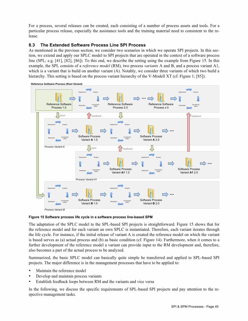
SPI & SPM Processes - Page 45
For a process, several releases can be created, each consisting of a number of process assets and tools. For a particular process release, especially the assistance tools and the training material need to consistent to the re-lease.
8.3 The Extended Software Process Line SPI Process As mentioned in the previous section, we consider two scenarios in which we operate SPI projects. In this sec-tion, we extend and apply our SPLC model to SPI projects that are operated in the context of a software process line (SPL; e.g. [41], [82], [86]). To this end, we describe the setting using the example from Figure 15. In this example, the SPL consists of a reference model (RM), two process variants A and B, and a process variant A1, which is a variant that is build on another variant (A). Notably, we consider three variants of which two build a hierarchy. This setting is based on the process variant hierarchy of the V-Modell XT (cf. Figure 1; [85]).
Figure 15 Software process life cycle in a software process line-based SPM
The adaptation of the SPLC model to the SPL-based SPI projects is straightforward. Figure 15 shows that for the reference model and for each variant an own SPLC is instantiated. Therefore, each variant iterates through the life cycle. For instance, if the initial release of variant A is created the reference model on which the variant is based serves as (a) actual process and (b) as basic condition (cf. Figure 14). Furthermore, when it comes to a further development of the reference model a variant can provide input to the RM development and, therefore, also becomes a part of the actual process to be analyzed.
Summarized, the basic SPLC model can basically quite simple be transferred and applied to SPL-based SPI projects. The major difference is in the management processes that have to be applied to:
• Maintain the reference model • Develop and maintain process variants • Establish feedback loops between RM and the variants and vice versa
In the following, we discuss the specific requirements of SPL-based SPI projects and pay attention to the re-spective management tasks.
Analysis(
Conceptualiza1on(Realiza1on(
Deployment(
Reference Software Process 1.0
Reference Software Process 2.0
... Reference Software
Process x.0
Analysis(
Conceptualiza1on(Realiza1on(
Deployment(
Software Process Variant A 1.0
Analysis(
Conceptualiza1on(Realiza1on(
Deployment(
Software Process Variant A 2.0
...
Analysis(
Conceptualiza1on(Realiza1on(
Deployment(
Software Process Variant A1 1.0
Analysis(
Conceptualiza1on(Realiza1on(
Deployment(
Software Process Variant A1 2.0
...
Analysis(
Conceptualiza1on(Realiza1on(
Deployment(
Analysis(
Conceptualiza1on(Realiza1on(
Deployment(
Software Process Variant B 1.0
Analysis(
Conceptualiza1on(Realiza1on(
Deployment(
Software Process Variant B 2.0
...
Reference Software Process (Root Variant)
Process Variant A
Process Variant A1
Process Variant B
Feedback
Feedback
Feedback Input
Input
Input
Page 46 - The Extended Software Process Line SPI Process
8.3.1 SPL-based SPI Projects – Specific Requirements In order to extend and apply the SPLC model to SPL-based SPI projects, we have to pay attention to the specific requirements of SPL-based processes. We discuss these requirements using the example from Figure 15. In the figure, a reference model and a number of derived variants are shown that have dependencies between each other. The most obvious dependency is a parent-child relationship between a reference model and a variant, whereby a variant can also serve as reference model for further variants (cf. Figure 15, variant A and variant A1). Such a relationship implies several requirements:
Requirement Description
R1 Evolutionary changes of the reference process need to be propagated to the variants.
R2 Changes and differences need to be recognizable and easy to adopt.
R3 Feedback from single variants must be available for other variants, too.
R4 A global notion of process quality needs to be introduced, e.g. by defining a conformity term.
The previously listed requirements are still challenging tasks. For instance, much effort was spent in determin-ing evolutionary changes in comprehensive software processes. The group around Münch [70], [71], [72] worked on this problem in the context of the V-Modell XT. Their results provided insights into the evolution of a process and, at the same time, analyzed the evolution of a reference model and its impacts to derived process variants, changes in a variant that are affected by a change in the reference model, and changes of several vari-ants in relation to a reference model to compare parallel evolution of reference models and variants. However, although the analyses were comprehensive and informative, the decision which changes directly affect a par-ticular variant and thus have to be implemented still had to be made by a process engineer.
In response to this particular situation, e.g. the V-Modell XT’s metamodel was revised in accordance with the process line approach in which SPL-based variants are created an explicit set of so-called variability operations, which – under optimal conditions – allow for automatic updates [86].
While the first two requirements are more of technical nature and, therefore, can be addressed using a respective modeling and design approach, the other requirements address organizational questions. Establishing a feedback loop that allows for providing the reference model with feedback from the variants, especially when problems in the development of a particular variant occur, requires – at least – a mature change management. For instance, in project 2 from Table 1 several technical issues and shortcomings in the reference model 1-RM were revealed that caused certain improvements in the variants backbone, which were later considered in the improvement of the reference model. If working in the context of a process line, the reference model defines the basic contents and structure and, therefore, gives the basic notion of the SLP-wide quality and conformity requirements. Such quality requirements are important, e.g. to ensure the comparability of certain process variants (for instance, if project member work in different projects), or to allow for certification.
The SPLC supports those requirements by using the artifact model. For instance, in order to determine adapta-tions and extensions of a reference model, an SPL- Delta report is assigned to each process variant. This report contains a summary of all applied variability operations, affected process assets, and a rationale. On the one hand, this report documents the differences between the reference model and a particular variant and, on the other hand, this report supports the determination of the degree of conformance, e.g. by rating the applied varia-bility operations whether the application is noncritical or subject to further quality assurance. Furthermore, the report reflects the actual implementation and allows the comparison with the planned customizations and hence is also an important input for the quality assurance. In order to establish communication and feedback loops, the artifact model defines several artifacts dealing with change management, which is an integral part of a SPI pro-ject. Furthermore, artifacts dealing with process assessments and quality management are also part of the arti-fact model (more on this topic in the next section).
8.3.2 Management Processes SPI projects have to be organized and implemented according to software development projects. To this end, a number of management processes have to be defined and implemented, especially when dealing with SPI en-
SPI & SPM Processes - Page 47
deavors that are based on software process lines. As single-SPI projects can usually operated in a rather prag-matic/straightforward management style, SPL-based projects require mature:
• Project management • Quality management • Change management • Configuration management • Release management
In the following, we focus on the quality, change, and release management for SPI projects.
Important
In the following, we describe the management processes using the artifacts from our artifact model. The description is intentionally underspecified and focuses on the required artifacts. It is the responsibility of the implementing organization to fill the gaps, especially on the organization layer as we assume corresponding processes to be already in place.
8.3.2.1 Quality Management The quality management processes (incl. quality assurance) are based on the QA-related artifacts (Sect. 7.2.1). We distinguish two basic perspectives:
1. Overall quality management 2. Quality assurance
The quality management (QM) relates to the whole process or the entire process line. On this level, several artifacts might be necessary in order to define an appropriate QM:
• Process Assessment • Conformity Assessment Report • SPL-Delta Report • Metric Catalog (incl. Metric)
The metric catalog (and also the metric) is an artifact that links the QM with project and process management. The metrics and KPIs are conducted in projects; the QM defines the initial definitions, which metrics and KPIs are of interest. To this end, the organization that operates SPI programs needs to establish measurement pro-grams regarding project- and process performance that includes the definition of metrics and the measurement in the projects.
As part of a measurement program, process assessments serve as reported activities regarding, e.g. the process performance (determination of maturity levels, gap analyses, etc.). In special cases, e.g. conformance or compli-ance to certain standards or customer requirements needs to be proved, an assessment addressing conformance or compliance needs to be conducted and documented in a conformity assessment report. Both assessments refer to the measurement and evaluation strategy, which is defined in the process life cycle support documenta-tion (Sect. 7.1.4), and to the process or the process line (Sect. 4.1.2).
In addition, especially again in the context of a conformity check of a process variant in a SPL-based setting, a SPL-Delta report explicitly documents changes that were done using planned operations as defined by the pro-cess line. The application of such variability operations has to be declared in the technical process design (logi-cal and physical model organization; Sect. 7.1.3), and refers to a particular process release, the process or re-spectively the process line.
In order to implement a software process management (SPM), an organization needs to implement processes that support:
• The definition of metrics as well as a corresponding measurement • Measurement and evaluation activities that address the organization level, and that can be instantiated in the
projects to be monitored • Determination of deviations of process variants in a process line in order to measure conformance, compli-
ance, etc.
Page 48 - The Extended Software Process Line SPI Process
On the SPI project level, we demand as minimum the creation of the following artifacts in order to establish a quality assurance for the project:
• Quality Assurance Manual (QA Manual) • Quality Assurance Plan (QA Plan) • Test Specification • Test Protocol • Quality Assurance Report (QA Report)
The QA manual is the playbook, which contains all definitions regarding the QA activities in a SPI project. Such definitions comprehend the process assets that shall be tested as well as the corresponding test methods and the test criteria. Test criteria should be defined on QM level and context-specific transferred to a project, e.g. a subset of metrics. For every process asset that is mentioned in the QA, a test specification has to be creat-ed (the detailed definitions are documented in the QA manual). The respective test protocols document the test procedure, e.g. a review for a process documentation asset, a checklist for a check regarding the completeness of artifacts or activities. Since the QA manual names all assets that have to be considered for QA activities and test specifications contain the particular tests, all these activities need to be included in the project’s schedule. This is the task of the QA plan in which the QA activities are scheduled. Finally, the QA report documents the overall project status regarding the quality aspects.
The QA manual, the QA plan, and the QA report are artifacts that build the interface to the project management activities.
Remark
There is one QA activity that often occurs in SPI projects: the user evaluation. Actually, the user evaluation is part of the measurement program. Anyway, such evaluations are often done in combination with QA measures (reviews). To this end, the user evaluation plan is also related to the QA plan if such activities are done in a project. One has to differentiate between a “general” user evaluation in the context of the “global” measurement and the user evaluation in a particular improvement project.
Further details regarding fine-grained QM and QA activities are modeled in the complementing process model.
8.3.2.2 Change Management For the change management, we selected a very simple approach, which also worked fine in our projects. In the change management, which is part of the process life cycle support documentation (Sect. 7.1.4), it has to be defined, what kinds of changes exist and how to handle occurring changes. To this end, the artifact model con-tains only three artifacts:
• Change (abstract element to link further artifacts) • Issue • Feature Request
A change always refers to a process asset. An issue is a problem with the process or any of the contained pro-cess assets. A feature request is also a change request, which aims at including a new feature to a process.
Change management has to be considered on two levels, again. At first, change management to be defined in the context of the SPI project, e.g. a review requires a change to be implemented in the next iteration (Figure 16). This kind of change management is a part of the project organization, which is documented in the project manual (Sect. 7.2.2).
The second “style” of change management is the management of the evolution of a software process or of the entire process line. An example is given in Figure 15. In the figure, a reference process is show that serves as basis for several variants. Change management in this context has some additional tasks:
• Evolutionary changes of the reference model have to be propagated to the derived variants • New developments or changes from certain variants have to be checked, whether they could provide bene-
fits to the reference model and, therefore, can become a change request for the reference model • Impact analyses have to be made more carefully as they might affect several variants
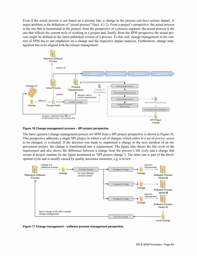
SPI & SPM Processes - Page 49
Even if the actual process is not based on a process line, a change in the process can have serious impact. A major problem is the definition of “actual process” (Sect. 4.1.2). From a project’s perspective, the actual process is the one that is instantiated in the project; from the perspective of a process engineer, the actual process is the one that reflects the current style of working in a project and, finally, from the SPM perspective the actual pro-cess might be defined as the latest published version of a process. To this end, change management in the con-text of SPM has to put emphasize on a change and the respective impact analyses. Furthermore, change man-agement has to be aligned with the release management.
Figure 16 Change management process – SPI project perspective.
The basic (generic) change management process for SPM from a SPI project perspective is shown in Figure 16. This perspective addresses a single SPI project in which a set of changes, which refers to a set of process assets to be changed, is evaluated. If the decision was made to implement a change in the next iteration of an im-provement project, the change is transformed into a requirement. The figure also shows the life cycle of the requirement and also shows the difference between a change from the process’s life cycle and a change that occurs at project runtime (in the figure mentioned as “SPI project change”). The latter one is part of the devel-opment cycle and is usually caused by quality assurance measures, e.g. a review.
Figure 17 Change management – software process management perspective.
Actual Process
Reference Software Process
instance of
Change List
Change Process Asset
contains
refers to Evaluate(Change(
Decision: implement later OR not in SPI project scope ! to process line
Process Requirements
Decision: add to process requirements
Analysis Conceptualization Realization Deployment
Change ! Requirement
Analyze(Requirement(
Conceptualize(Requirement(
Realize(Requirement(
Integrate(&(Deploy(Requirement(
Realized Requirement
Test(Requirement(Realiza=on(
SPI Project Change
Reference Software Process
report change to the SPL’s central change management
Change
input for improvement
change in a reference process
for each affected process variant Software Process
Variant A
Evaluate(Change( Propagate(Change(
Propagate(Change(
Propagate(Change(
Change
Change
Change
Software Process Variant B
Software Process Variant C
input for improvement
Local Change
Evaluate(Change(
Page 50 - The Extended Software Process Line SPI Process
In Figure 16, the project-internal perspective, and the difference between life-cycle-based and project-internal changes are shown. While the internal changes are caused by development activities, the management of the software process causes the life-cycle-based changes. In Figure 17, a scenario is given in which a change is caused by a reference process. The change is evaluated and propagated to all affected process variants. The change becomes an input for the further improvement, is evaluated in the SPI project, and so on (see Figure 16).
We call a setting in which the change is “actively” propagated to dependent variants directed evolution – as for instance shown in the context of the V-Modell XT (Sect. 1.1; the reference process causes changes in the par-ticular variants). The other way, if a change is raised by a variant, e.g. by defining a new best practice or an improvement, the change can also become relevant for reference process and further process variants. To this end, the change is evaluated and reported back to the central change management. We call such a setting prac-tice-driven improvement.
Remark
Changes in a software process that is a variant of a software process line often cause SPI projects to analyze, design, realize, deploy, and evaluate the change. In other words: While a change on the SPI project level usually causes a task, e.g. “…implement this…”, a change on the SPM level often causes a whole SPI project, e.g. “…implement support for this new RE approach…”.
8.3.2.3 Release Management Taking the example from Figure 15, the necessity of a mature release management becomes obvious. For in-stance, an evolution in the reference model may cause new releases for the variants as well. To start the devel-opment on a new variant, the reference model should be stabilized and released in order to build the variant on a solid basis (for instance, in the project 4 from Table 1 we experienced the “moving target” syndrome, which caused additional effort as we had to start the project twice).
The release management is responsible to state:
• Which features are new implemented in the process (methodical as well as technical) • Which issues/feature requests are included and which remain open issues • What is the corresponding technical backbone
The technical backbone is crucial. In our technical report [85], we investigated the V-Modell XT family and learned that each release required a specific configuration of technical components – a downward compatibility was not always given.
Regarding the features, new features in terms of determining the conformance might affect variants. Further-more, if a variant of a process line was created using variability operations, changes in the reference model could affect the variability operations, e.g. a role was renamed in a variant and in an evolved reference model the new name was adopted then the particular variability operation is obsolete and, therefore, should be re-moved.
Furthermore, the release management should define what is in a particular process release (Sect. 0), which pro-cess assets build the process, which tools are shipped, and so on. Also, the release management should allow for identifying a release in the roadmap (Sect. 7.1.4).
Since the release management also depends on the technical infrastructure with which the process is authored and built, agreements are necessary to determine:
• What is part of a release? • Is there an integrated build management (tool), and how to use it? • Who are the players initiating the build, packaging, and deployment? • How is the process deployed (e.g., set of HTML-pages, installer, and so forth)? • Who is responsible to update plans and management procedures? • How to find the right version/release/build-numbers (e.g. what is a major/minor release)? • …
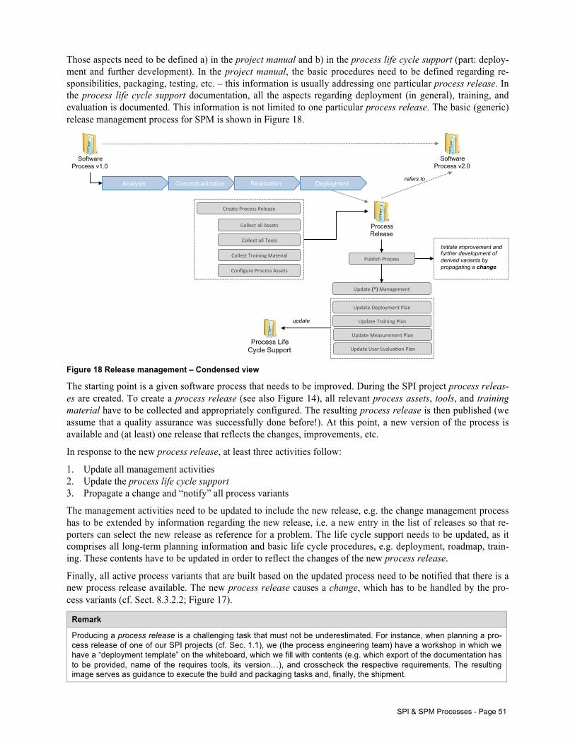
SPI & SPM Processes - Page 51
Those aspects need to be defined a) in the project manual and b) in the process life cycle support (part: deploy-ment and further development). In the project manual, the basic procedures need to be defined regarding re-sponsibilities, packaging, testing, etc. – this information is usually addressing one particular process release. In the process life cycle support documentation, all the aspects regarding deployment (in general), training, and evaluation is documented. This information is not limited to one particular process release. The basic (generic) release management process for SPM is shown in Figure 18.
Figure 18 Release management – Condensed view
The starting point is a given software process that needs to be improved. During the SPI project process releas-es are created. To create a process release (see also Figure 14), all relevant process assets, tools, and training material have to be collected and appropriately configured. The resulting process release is then published (we assume that a quality assurance was successfully done before!). At this point, a new version of the process is available and (at least) one release that reflects the changes, improvements, etc.
In response to the new process release, at least three activities follow:
1. Update all management activities 2. Update the process life cycle support 3. Propagate a change and “notify” all process variants
The management activities need to be updated to include the new release, e.g. the change management process has to be extended by information regarding the new release, i.e. a new entry in the list of releases so that re-porters can select the new release as reference for a problem. The life cycle support needs to be updated, as it comprises all long-term planning information and basic life cycle procedures, e.g. deployment, roadmap, train-ing. These contents have to be updated in order to reflect the changes of the new process release.
Finally, all active process variants that are built based on the updated process need to be notified that there is a new process release available. The new process release causes a change, which has to be handled by the pro-cess variants (cf. Sect. 8.3.2.2; Figure 17).
Remark
Producing a process release is a challenging task that must not be underestimated. For instance, when planning a pro-cess release of one of our SPI projects (cf. Sec. 1.1), we (the process engineering team) have a workshop in which we have a “deployment template” on the whiteboard, which we fill with contents (e.g. which export of the documentation has to be provided, name of the requires tools, its version…), and crosscheck the respective requirements. The resulting image serves as guidance to execute the build and packaging tasks and, finally, the shipment.
Analysis Conceptualization Realization Deployment
Software Process v1.0
Software Process v2.0
Process Release
refers to
Create&Process&Release&
Collect&all&Assets&
Collect&all&Tools&
Collect&Training&Material&
Configure&Process&Assets&
Publish&Process&
Initiate improvement and further development of derived variants by propagating a change
Update&(*)&Management&
Update&Deployment&Plan&
Update&Training&Plan&
Update&Measurement&Plan&
Update&User&Evalua?on&Plan&Process Life
Cycle Support
update
Page 52 - Analysis and Design Decisions
8.4 Analysis and Design Decisions Several of the aforementioned analysis and design steps depend on the particular setting of the SPI project. From our projects, we could extract some key questions that influence either the whole project or parts of it. In the following we list these questions and discuss their implications.
8.4.1 What is the purpose of the SPI project? The first and most important question is for the project goals. The goal definition addresses basic conditions (cf. process requirements; Sect. 7.1.1) as well as the purpose of the SPI project. Exemplary purposes are:
• Deployment of a standard software process: The intention of this particular approach is to replace a pro-prietary process by a standardized software process. When selecting this option, special attention has to be paid to the analysis phase. Also, during the conception phase first considerations regarding the process in-frastructure have to be made as the process engineering team as well as the process consumers have to get familiar with the potentially new process engineering framework and the corresponding tools. Such a re-placement usually requires a fully instantiated artifact model as the whole process and its environment need to be designed.
• Improvement of already deployed software processes: A given process needs to be improved and, therefore, all the material that is already present in the organization needs to be identified in the analysis phase. Spe-cial attention needs to be paid on the input material, on gap analyses, and on (available) key performance indicators in order to identify the process parts to be improved (cf. assessment-related artifacts; Sect. 9.1).
• Migration to a standard software process engineering environment: This setting is comparable to the first setting. The difference is that the process contents are not a subject of improvement and that only the tech-nical infrastructure needs to be reorganized (the project 4 from Table 1 is an example). Anyway, using a new infrastructure might also cause several changes in the process model and, therefore, the impacts have to be analyzed quite detailed to ensure the new process provides the same information and support as the old one. A reason for this setting is the migration in order to initiate a long-term management of the soft-ware process, e.g. the old process is documented using textbooks while the new infrastructure uses model-ing tools that allow for better dealing with evolution.
The purpose directs the entire SPI project by defining the overall goal (cf. process requirements; Sect. 7.1.1). Each single design decision is potentially influenced by the initial goal definition.
The goal definition is complemented by certain basic conditions that also influence design decisions, the im-plementation approach, and so forth. Exemplary basic conditions are:
• Typical projects: A process should reflect the typical projects in which the process shall be applied. If the new process does not reflect the projects’ demands appropriately, the process will be rejected. Furthermore, the information regarding the typical projects provides important information which tailoring criteria [39] could be of interest. This condition has impact on the tailoring model (cf. conceptual process design and technical process design).
• Conformance requirements: Conformance constraints provide, e.g. regulations and requirements that the considered process needs to address. Such constraints depend on the particular domain in which the process shall be applied, e.g. automotive, aerospace, or medicine. This condition has impacts on the quality assur-ance and process assessments that have to be planned accordingly.
• Existing processes: Beyond the software development, organizations usually define a number of further processes, e.g. sales, operations, and decision-making processes at the management level. Such (business or decision-making) processes need to be addressed by the considered process in order to be seamlessly em-bedded in the hosting organization. For instance, in the projects 3, 4, and 6 from Table 1 the interfaces to the organization were of special importance. Especially in the project 6 the definition of the interfaces was essential while the definition of the development process was not that challenging. This condition has im-pact on the process requirements and the conceptual process design.
• Tools: A 1,000-page process documentation is worth nothing as nobody will read the documentation in a project that has to deal with other “problems”. Furthermore, developers that have to code may be more in-terested in a support, e.g. addressing the used work item tracking system. Another perspective is the infra-structure that process engineers use to implement the process. For instance, if a comprehensive project-
SPI & SPM Processes - Page 53
specific tailoring model is required the SPEM-based EPF environment is not meaningful. On the other hand, the V-Modell XT infrastructure is completely in German and, therefore, is limited in its international applicability. This condition has impacts on the process requirements and the technical process design.
8.4.2 Which kind of knowledge is already present in the organization? This question aims at the existing process related knowledge of the organization driving the SPI project and can include a maturity level, e.g. CMMI or ISO 15504. Taking into account the existing knowledge, the whole pro-ject can be influenced, e.g. stakeholders do (not) know what it means to initiate a SPI project and, therefore, have (no) illusions about the reachable goals. From the perspective of the process engineer, the existing knowledge results in different approaches, e.g. different analysis and design approaches, different communica-tion, or higher demands in training or project marketing (cf. process requirements; 7.1.1, conceptual process design; 7.1.2, process life cycle support; 7.1.4).
8.4.3 Which kind of input material is available? Even if a software process is not explicitly documented, the normal case is that some material is always in place. The fist step is, therefore, to figure out which kind of material is available and what is the material’s qual-ity. For instance, when it comes to an improvement project, the “old” process has to be analyzed. In the projects 3 and 4 from Table 1 rich and mature material was available for analyses, reuse, and further development. In [54], we presented a student project in which the process under consideration was defined almost 10 years ago and did not reflect the actual procedures at all. Anyway, although this input material was hard to reuse it had to be analyzed to get the basic information required to talk to the client. The kind of the available input material influences the whole project as it has impact on the analysis processes and may also affect the project goals (cf. process requirements; 7.1.1, conceptual process design; 7.1.2).
8.4.4 Which development strategy shall be applied? This is also in important question that also depends on the process framework. For instance, although the con-ceptual process design (Sect. 7.1.2) is usually created following a bottom-up approach, the V-Modell XT re-quires (partially) a top-down development for the realization [59]. Although the artifacts (V-Modell XT: work products) are quite early defined, for their implementation a tailoring module is required, which is a container element that is rather late defined in the definition of the tailoring model (cf. conceptual process design; 7.1.2, technical process design; 7.1.3). Another example: During our study in [54], we found several issues regarding collaborative and parallel work using SPEM (Eclipse Process Framework (EPF) environment and Subversion), which forced the process engineering teams into a sequenced work style. In the organization of the realization phase, such requirements and (known) weaknesses need to be taken into account.
To this end, the concrete approach depends on the basic decision, how the process can and shall be implemented (which also depends on the selected framework):
• Develop a software process from scratch: If a process shall be developed from scratch, a comprehensive planning and management is required. Each process asset has to be analyzed, designed, implemented, and tested. To this end, a fully instantiated artifact model (cf. Sect. 9.1) is required in order to address all as-pects, the process engineering and, beyond, project management, quality management, release management, training, and so forth.
• Customize a given standard software process: Customizing a standard software process is, on the first sight, an efficient approach as it allows for reusing standardized contents. However, in the requirements phase and in the analysis phase detailed analyses have to be made to clearly define the purpose of the intended pro-cess, and to figure out how the standard process can contribute to the identified goals. To this end, process assets from the standard process that shall be reused need to be identified. Furthermore, necessary customi-zations need to be defined, e.g. extensions to existing artifacts, or (as a simple example) required renaming of roles or artifacts. Accordingly, the conceptualization and the realization have to address two aspects: (1) the customization of the reused process assets and (2) the design, realization, and integration of the new process assets. This condition has impacts on the conceptual process design.
• Create a variant in a software process line: The creation of a process variant, which is based on a software process line (SPL), is comparable to the customization setting. However, there are differences in the ap-proach as the customization options a process engineer can use are usually limited by the infrastructure on
Page 54 - Analysis and Design Decisions
which the SPL is built. A process engineer has to figure out which operations are available and “allowed”. Furthermore, SPLs usually have certain conformance constraints and, therefore, several additional artifacts, e.g. a SPL-Delta report, or several assessments (cf. Sect. 9.1) have to be created. This condition has impacts on the conceptual process design and on the technical process design.
8.4.5 Which implementation technique shall be applied? Although this is a technical question, the implementation technique – the process engineering framework – has to be defined as soon as possible. While the process requirements and the conceptual process design can be created without paying much attention to technical or realization-related question, at latest when starting the process realization the process engineering framework has to be defined and it also has to be in place.
In an initial iteration, e.g. prototypes can be used to evaluate process engineering frameworks (Figure 13), solu-tions can be compared and evaluated – as exemplary done in [54] – however, at a certain point the decision has to be made as the process engineering framework has massive implications on fine-grained process designs.
Example
For instance, SPEM and the V-Modell XT have each a different notion of the importance of artifacts. Consequently, selecting either the one framework or the other limits the available design elements, e.g. SPEM does not support fine-grained artifact dependencies, and the V-Modell XT does not support fine-grained workflows.
For the refinement of the conceptual process design (Sect. 7.1.2) in the technical process design (Sect. 7.1.3), such a decision is important as the realization models highly depend on the available technical design elements. To this end, the implementation technique depends on the selected infrastructure and also influences the refine-ment from the conceptual process design to the technical process design. An exemplary implication is the de-sign refinement regarding the criteria for structuring the process assets:
• Emphasis on processes and activities: This design criterion highlights the question for “what is done”. Low-level activities (also single tasks) are collected, structured, and generalized. The purpose is creating some kind of workflow that links the players to the necessary activities. Artifacts are inputs and outputs of the workflows (cf. Sect. 9.4.2.3); dependencies between the artifacts are expressed by dependencies be-tween the activities (data-flow). This approach can – on the one hand – be used to create activities based on an actual process, but also – on the other hand – to define fine-grained methods in which every single activ-ity can be described in every detail.
• Emphasis on artifacts: The concentration on artifacts is a more general approach. Concrete methods are not in the spotlight. The relevant information is given by the question for “what is produced”. Avoiding con-crete method descriptions gives the process consumers the freedom to select their favored methods to do certain tasks – as long as the artifacts are produced in the required structure and in the required quality. The challenge is to take control of the dependency network (cf. Sect. 9.4.2.2). Since artifacts are no longer input and output for workflows, the dependencies between the artifacts need to be differently expressed, e.g. which artifact causes the creation of another one. Also, for designing and implementing a process the arti-fact-based approach shows some advantages, e.g. comprehensive models, ease of understanding dependen-cies [54].
In order to allow for a collaborative development, a long-term evolution and maintenance, and a process tailor-ing, criteria for structuring process assets influence the creation of reusable building block (process modules).
8.4.6 Which deployment strategy is feasible? The deployment strategy influences many aspects of a SPI project, e.g. project planning in general, and de-ployment-/release management or training planning in particular. Furthermore, the deployment strategy is polit-ically critical aspect as schedules have to be aligned and transitional arrangements have to be made. Basically, three deployment strategies can be distinguished:
• Big Bang: The big bang strategy sets a deadline. All new projects have now to use the new process. For existing processes either transitional arrangements have to be made or migration strategies have to be worked out.
SPI & SPM Processes - Page 55
• Stepwise: Using a stepwise migration means that not the whole process is introduced at a time, but selected sub-processes are deployed step-by-step, e.g. a new requirements engineering process or a new test process.
• Pilot projects: Strongly related to the stepwise process deployment, a deployment via pilot projects is an-other deployment strategy. In this strategy, selected projects use a new process to (1) test and evaluate the new process, and (2) to train the people and to create promoters.
All strategies bear risks and chances. For instance, the big bang strategy sets a clear deadline and, therefore, all projects know which process is the one that counts. On the other hand, potentially untrained people have to use a new process, which may increase usage mistakes or which may cause quality and scheduling problems. The stepwise deployment has the advantage that selected processes can be deployed to selected projects. The disad-vantage is that the whole deployment process takes longer since all parts of the process have to be deployed step-by-step. This may also complicate the process maintenance as, for instance, feedback of already deployed sub-processes comes in and needs to be considered for “bug fixing” while other parts of the process are not yet deployed at all (Sect. 8.3.2).
An effective and proved deployment strategy is the deployment via pilot projects in which the new process is tested and evaluated, and awareness regarding the new process can be generated. Furthermore, pilot projects can serve as reference projects that can create initial KPIs, which can be compared to KPIs from already completed projects, and that can also build a basis for further measurement (Sect. 8.3.2.1). However, driving a pilot project is hard and most pilot projects suffer from the new process: newly introduced methods have to be learned and optimized, pilot projects bear conflict potential as they might not be “that successful” as expected (too expen-sive, too late). Therefore, when it comes to pilot projects:
• The “right” projects need to be defined in which the “right” people work. • The right project is not too big and not business critical. • The right project meets the improvement goals and allows for measurement. • The right project can withstand evolving processes.
Using pilot projects as means to deploy a new process requires intensive communication. The management has to respect that a pilot project may be late, and that a pilot project may have quality issues. Anyway, the man-agement has to recognize this particular situation and the process engineers should have an eye on the project flow: quality issues can occur – but their number should decrease over time. An important remark: Sometimes, there is no appropriate pilot project.
8.4.7 How to organize the training schedule? The organization of the training is also an important aspect that affects the SPI project. Detailed discussion on this topic can be found, e.g. in [4]. In terms of our model, the organization of the trainings is relevant when creating the release plans. Training material is part of a process release and, therefore, part of a delivery. Fur-thermore, if it was decided to, e.g. create awareness by involving early adopters or the top management, training material has also be created besides the usual development and release cycles.
Same as for requirements or the process in general, training material needs to be designed, implemented, and tested. It is important to define which stakeholder groups should participate in trainings and what is the relevant content. Therefore, the planning and the design for the training material is an important task during the creation of the conceptual process design (Sect. 7.1.2).
Remark
Another aspect that needs to be considered when planning the trainings: Trainings are, from the perspective of a pro-cess engineer, a quick win. It is a good forum to get feedback. Also, experience shows that participants use trainings to vent their frustrations, which is a good chance for a process engineer to get further insights into weaknesses that might be overseen during the analyses.
Page 56 - Artifact Catalog
9 Further Information
9.1 Artifact Catalog In this appendix, all artifacts are described in detail. For each artifact, the name is given, the kind, and further information. The kind of the artifact categorizes the artifact to be a key artifact (mandatory), an external arti-fact, or an artifact that is optional. An external artifact is given by, e.g. complementing processes such as project management. Such artifacts are required to operate a project, but do not contribute content to the process im-provement.
Artifact Type Kind Further Information
Conceptual Process Design K The conceptual process design contains all designs of a process without paying attention to any technical realization. It refines all process-related requirements and transfers them into concrete processes and process parts.
Technical Process Design K The technical process design refines the conceptual process design w.r.t. a concrete technical implementation and the tool/tool infrastructure to be used for the process’s realization.
Process Requirements K The process requirements contain all requirements regarding the process development.
Process K The process is the subject of interest. The process is the entire package that contains the process (description) itself, the corresponding tools, and additional material, e.g. training material. Since a process is a long-living entity, evolution and deployment require process releases. Each process can have multiple releases.
Deployment Plan O Each process, at least comprehensive ones, should have a respective deployment plan in which is documented, e.g. which releases are de-ployed, for whom, or which particular (sub) process have to be deployed and evaluated.
Measurement Plan O The measurement plan contains all information on measuring the pro-cess improvement, which includes several parameters on product, pro-cess, and project performance. A measurement plan is based on a measurement strategy in which defines metrics that are of interest for a particular SPI project.
Training Plan O The training plan contains all information regarding the planned trainings for the process consumers. The consumers can be: process engineers (for maintaining and further developing the process), quality managers, the company’s management, and the process users (project teams).
User Evaluation Plan O While the measurement plan of a process aims at measuring the process performance in general, a user evaluation plan aims at evaluation the actual use of a process. In contrast to “classic” KPI-based measuring, the user evaluation is more of a qualitative nature.
Contract E A contract defines the basic agreements on a SPI project. The contract is either a “formal” contract or an agreement – important: the contract has at least to contain the goals, work packages (that allow for planning), and a schedule that, all together, can be used to define a development strat-egy, a deployment strategy, a training strategy, and so forth.
Project Plan M The project plan contains all required planning information of the SPI project (not of the process under development). The project plan can, depending on the concrete project configuration, contain several plans, e.g. the deployment plan, the quality assurance plan.
Training Material O Training material consists of material to train the process consumers. The training material is specific for certain user groups/stakeholders and for particular releases. Usually, training material is explicitly defined for the stakeholder groups and, therefore, provides different perspectives and information on different levels of abstraction.
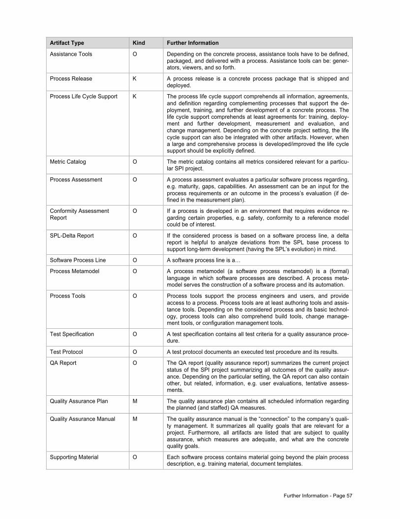
Further Information - Page 57
Artifact Type Kind Further Information
Assistance Tools O Depending on the concrete process, assistance tools have to be defined, packaged, and delivered with a process. Assistance tools can be: gener-ators, viewers, and so forth.
Process Release K A process release is a concrete process package that is shipped and deployed.
Process Life Cycle Support K The process life cycle support comprehends all information, agreements, and definition regarding complementing processes that support the de-ployment, training, and further development of a concrete process. The life cycle support comprehends at least agreements for: training, deploy-ment and further development, measurement and evaluation, and change management. Depending on the concrete project setting, the life cycle support can also be integrated with other artifacts. However, when a large and comprehensive process is developed/improved the life cycle support should be explicitly defined.
Metric Catalog O The metric catalog contains all metrics considered relevant for a particu-lar SPI project.
Process Assessment O A process assessment evaluates a particular software process regarding, e.g. maturity, gaps, capabilities. An assessment can be an input for the process requirements or an outcome in the process’s evaluation (if de-fined in the measurement plan).
Conformity Assessment Report
O If a process is developed in an environment that requires evidence re-garding certain properties, e.g. safety, conformity to a reference model could be of interest.
SPL-Delta Report O If the considered process is based on a software process line, a delta report is helpful to analyze deviations from the SPL base process to support long-term development (having the SPL’s evolution) in mind.
Software Process Line O A software process line is a…
Process Metamodel O A process metamodel (a software process metamodel) is a (formal) language in which software processes are described. A process meta-model serves the construction of a software process and its automation.
Process Tools O Process tools support the process engineers and users, and provide access to a process. Process tools are at least authoring tools and assis-tance tools. Depending on the considered process and its basic technol-ogy, process tools can also comprehend build tools, change manage-ment tools, or configuration management tools.
Test Specification O A test specification contains all test criteria for a quality assurance proce-dure.
Test Protocol O A test protocol documents an executed test procedure and its results.
QA Report O The QA report (quality assurance report) summarizes the current project status of the SPI project summarizing all outcomes of the quality assur-ance. Depending on the particular setting, the QA report can also contain other, but related, information, e.g. user evaluations, tentative assess-ments.
Quality Assurance Plan M The quality assurance plan contains all scheduled information regarding the planned (and staffed) QA measures.
Quality Assurance Manual M The quality assurance manual is the “connection” to the company’s quali-ty management. It summarizes all quality goals that are relevant for a project. Furthermore, all artifacts are listed that are subject to quality assurance, which measures are adequate, and what are the concrete quality goals.
Supporting Material O Each software process contains material going beyond the plain process description, e.g. training material, document templates.
Page 58 - Tailoring the Artifact Model
9.2 Tailoring the Artifact Model Since SPI projects can have a different organizational context, different size, different purpose, and different objectives, not all of the aforementioned artifacts are necessary in every SPI project. However, the introduced artifact model reflects all requirements regarding the outcomes of an SPI project and, therefore, should be pre-sent in a SPI project. Although being relevant, the representation of the artifacts is not “that” important, and it is also not necessary to create each artifact as a self-contained document.
9.2.1 The Process Design In order to support smaller as well as bigger SPI projects, the artifact model supports certain tailoring options. The most important one is the merge of the two comprehensive design artifacts: the conceptual process design (Sect. 7.1.2) and the technical process design (Sect. 7.1.3).
The resulting artifact – the Process Design – is a “reduced” artifact that comprises the essential parts of both design artifacts. The process design was used in the projects 3 and 6 from Table 1 in order to reduce the docu-mentation effort (and also the maintenance effort for the design documents).
In which situation, both artifacts should be merged?
The artifacts should be merged in projects in which only small processes are developed or in that only sub-processes are the subjects. For instance, in project 6 a (relative) small method development process was de-signed, and the focus was on the embedding of the process into the organization. To this end, the process design contains only small pieces of artifacts and process parts; but the emphasize lays on the organization and role model, which is designed in every detail.
How to check that nothing important was forgotten?
The merge always bears the risk that important aspects are forgotten. To aid this situation, it is recommended to use the checklist from Sect. 9.3. Using this checklist, every artifact and sub-artifact, which each represent rele-vant contents (and activities), can be analyzed for:
• Relevance in the project • Creation and creation kind
Using the process design means that sub-artifacts from the conceptual process design and from the technical process design are usually mapped to the corresponding “chapters” of the integrated process design. In the checklist, every artifact can be labeled to be relevant or not, and if a particular sub-artifact was considered rele-vant, the checklist can be used again to check whether the required contents are realized in a project.
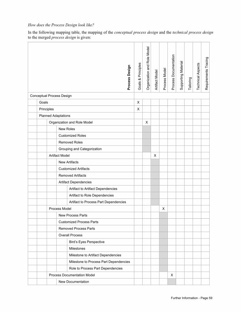
Further Information - Page 59
How does the Process Design look like?
In the following mapping table, the mapping of the conceptual process design and the technical process design to the merged process design is given:
Proc
ess
Desi
gn
Goa
ls &
Prin
cipl
es
Org
aniz
atio
n an
d R
ole
Mod
el
Artif
act M
odel
Proc
ess
Mod
el
Proc
ess
Doc
umen
tatio
n
Supp
ortin
g M
ater
ial
Tailo
ring
Tech
nica
l Asp
ects
Req
uire
men
ts T
raci
ng
Conceptual Process Design
Goals X
Principles X
Planned Adaptations
Organization and Role Model X
New Roles
Customized Roles
Removed Roles
Grouping and Categorization
Artifact Model X
New Artifacts
Customized Artifacts
Removed Artifacts
Artifact Dependencies
Artifact to Artifact Dependencies
Artifact to Role Dependencies
Artifact to Process Part Dependencies
Process Model X
New Process Parts
Customized Process Parts
Removed Process Parts
Overall Process
Bird’s Eyes Perspective
Milestones
Milestone to Artifact Dependencies
Milestone to Process Part Dependencies
Role to Process Part Dependencies
Process Documentation Model X
New Documentation
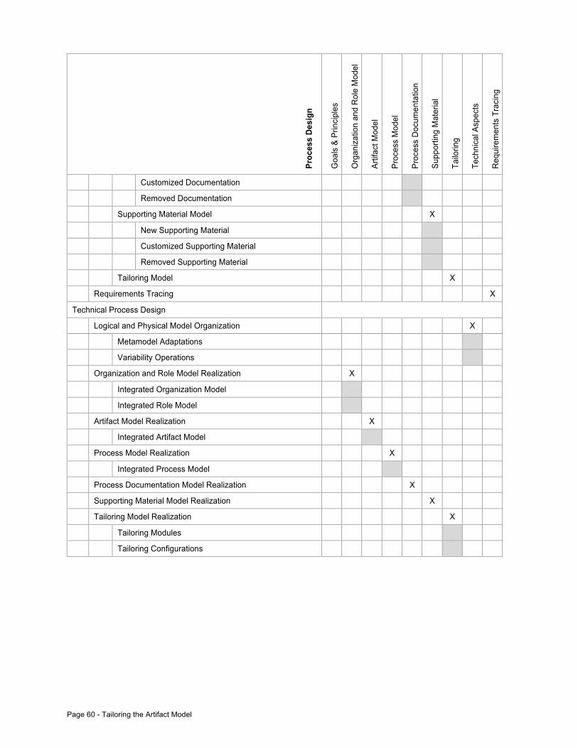
Page 60 - Tailoring the Artifact Model
Proc
ess
Desi
gn
Goa
ls &
Prin
cipl
es
Org
aniz
atio
n an
d R
ole
Mod
el
Artif
act M
odel
Proc
ess
Mod
el
Proc
ess
Doc
umen
tatio
n
Supp
ortin
g M
ater
ial
Tailo
ring
Tech
nica
l Asp
ects
Req
uire
men
ts T
raci
ng
Customized Documentation
Removed Documentation
Supporting Material Model X
New Supporting Material
Customized Supporting Material
Removed Supporting Material
Tailoring Model X
Requirements Tracing X
Technical Process Design
Logical and Physical Model Organization X
Metamodel Adaptations
Variability Operations
Organization and Role Model Realization X
Integrated Organization Model
Integrated Role Model
Artifact Model Realization X
Integrated Artifact Model
Process Model Realization X
Integrated Process Model
Process Documentation Model Realization X
Supporting Material Model Realization X
Tailoring Model Realization X
Tailoring Modules
Tailoring Configurations
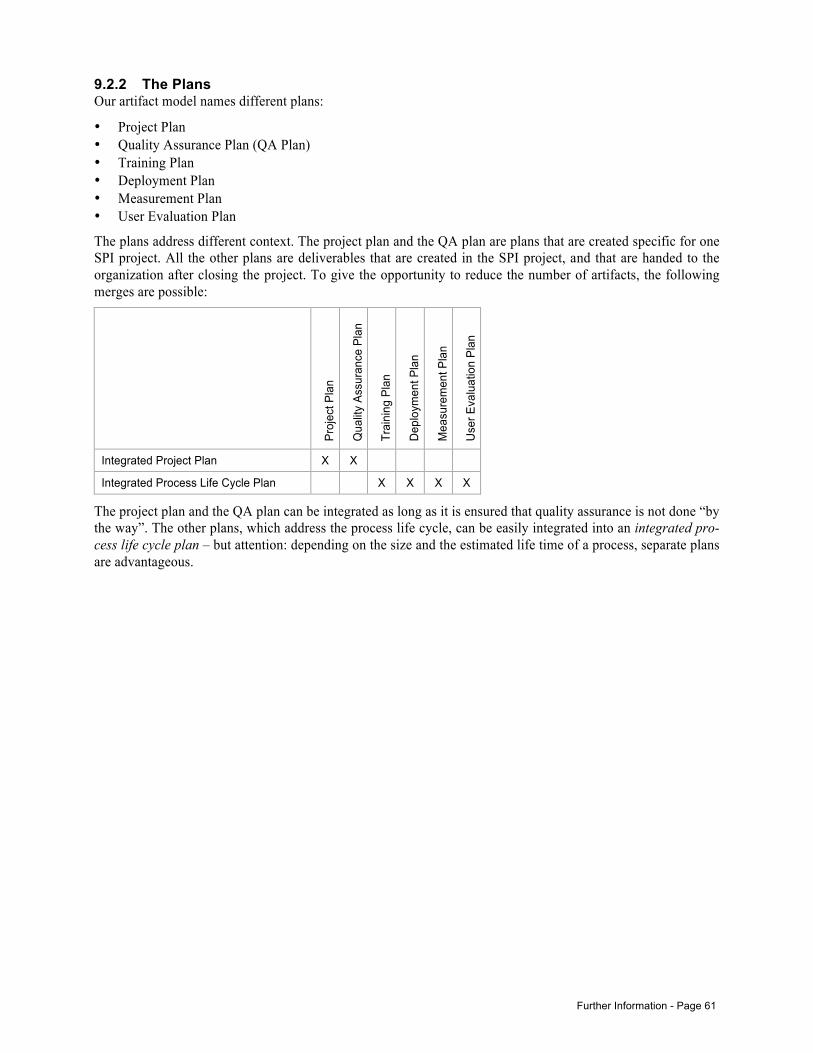
Further Information - Page 61
9.2.2 The Plans Our artifact model names different plans:
• Project Plan • Quality Assurance Plan (QA Plan) • Training Plan • Deployment Plan • Measurement Plan • User Evaluation Plan
The plans address different context. The project plan and the QA plan are plans that are created specific for one SPI project. All the other plans are deliverables that are created in the SPI project, and that are handed to the organization after closing the project. To give the opportunity to reduce the number of artifacts, the following merges are possible:
Proj
ect P
lan
Qua
lity
Assu
ranc
e Pl
an
Trai
ning
Pla
n
Dep
loym
ent P
lan
Mea
sure
men
t Pla
n
Use
r Eva
luat
ion
Plan
Integrated Project Plan X X
Integrated Process Life Cycle Plan X X X X
The project plan and the QA plan can be integrated as long as it is ensured that quality assurance is not done “by the way”. The other plans, which address the process life cycle, can be easily integrated into an integrated pro-cess life cycle plan – but attention: depending on the size and the estimated life time of a process, separate plans are advantageous.
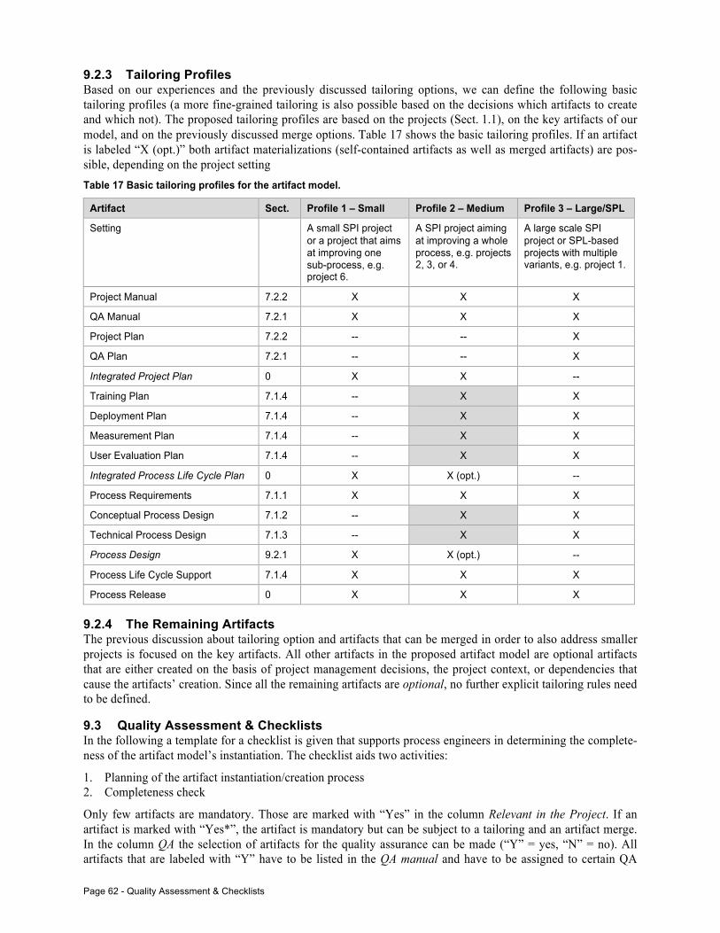
Page 62 - Quality Assessment & Checklists
9.2.3 Tailoring Profiles Based on our experiences and the previously discussed tailoring options, we can define the following basic tailoring profiles (a more fine-grained tailoring is also possible based on the decisions which artifacts to create and which not). The proposed tailoring profiles are based on the projects (Sect. 1.1), on the key artifacts of our model, and on the previously discussed merge options. Table 17 shows the basic tailoring profiles. If an artifact is labeled “X (opt.)” both artifact materializations (self-contained artifacts as well as merged artifacts) are pos-sible, depending on the project setting Table 17 Basic tailoring profiles for the artifact model.
Artifact Sect. Profile 1 – Small Profile 2 – Medium Profile 3 – Large/SPL
Setting A small SPI project or a project that aims at improving one sub-process, e.g. project 6.
A SPI project aiming at improving a whole process, e.g. projects 2, 3, or 4.
A large scale SPI project or SPL-based projects with multiple variants, e.g. project 1.
Project Manual 7.2.2 X X X
QA Manual 7.2.1 X X X
Project Plan 7.2.2 -- -- X
QA Plan 7.2.1 -- -- X
Integrated Project Plan 0 X X --
Training Plan 7.1.4 -- X X
Deployment Plan 7.1.4 -- X X
Measurement Plan 7.1.4 -- X X
User Evaluation Plan 7.1.4 -- X X
Integrated Process Life Cycle Plan 0 X X (opt.) --
Process Requirements 7.1.1 X X X
Conceptual Process Design 7.1.2 -- X X
Technical Process Design 7.1.3 -- X X
Process Design 9.2.1 X X (opt.) --
Process Life Cycle Support 7.1.4 X X X
Process Release 0 X X X
9.2.4 The Remaining Artifacts The previous discussion about tailoring option and artifacts that can be merged in order to also address smaller projects is focused on the key artifacts. All other artifacts in the proposed artifact model are optional artifacts that are either created on the basis of project management decisions, the project context, or dependencies that cause the artifacts’ creation. Since all the remaining artifacts are optional, no further explicit tailoring rules need to be defined.
9.3 Quality Assessment & Checklists In the following a template for a checklist is given that supports process engineers in determining the complete-ness of the artifact model’s instantiation. The checklist aids two activities:
1. Planning of the artifact instantiation/creation process 2. Completeness check
Only few artifacts are mandatory. Those are marked with “Yes” in the column Relevant in the Project. If an artifact is marked with “Yes*”, the artifact is mandatory but can be subject to a tailoring and an artifact merge. In the column QA the selection of artifacts for the quality assurance can be made (“Y” = yes, “N” = no). All artifacts that are labeled with “Y” have to be listed in the QA manual and have to be assigned to certain QA
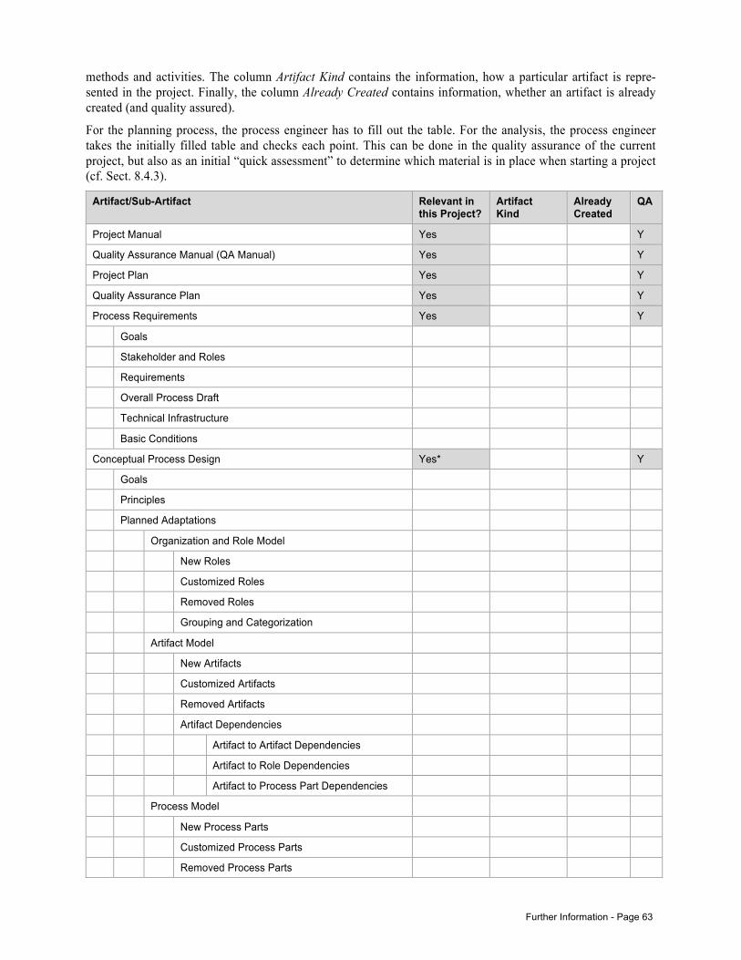
Further Information - Page 63
methods and activities. The column Artifact Kind contains the information, how a particular artifact is repre-sented in the project. Finally, the column Already Created contains information, whether an artifact is already created (and quality assured).
For the planning process, the process engineer has to fill out the table. For the analysis, the process engineer takes the initially filled table and checks each point. This can be done in the quality assurance of the current project, but also as an initial “quick assessment” to determine which material is in place when starting a project (cf. Sect. 8.4.3).
Artifact/Sub-Artifact Relevant in this Project?
Artifact Kind
Already Created
QA
Project Manual Yes Y
Quality Assurance Manual (QA Manual) Yes Y
Project Plan Yes Y
Quality Assurance Plan Yes Y
Process Requirements Yes Y
Goals
Stakeholder and Roles
Requirements
Overall Process Draft
Technical Infrastructure
Basic Conditions
Conceptual Process Design Yes* Y
Goals
Principles
Planned Adaptations
Organization and Role Model
New Roles
Customized Roles
Removed Roles
Grouping and Categorization
Artifact Model
New Artifacts
Customized Artifacts
Removed Artifacts
Artifact Dependencies
Artifact to Artifact Dependencies
Artifact to Role Dependencies
Artifact to Process Part Dependencies
Process Model
New Process Parts
Customized Process Parts
Removed Process Parts
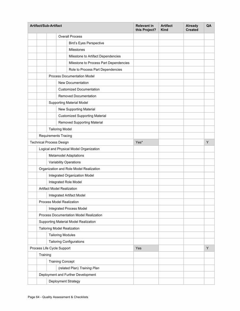
Page 64 - Quality Assessment & Checklists
Artifact/Sub-Artifact Relevant in this Project?
Artifact Kind
Already Created
QA
Overall Process
Bird’s Eyes Perspective
Milestones
Milestone to Artifact Dependencies
Milestone to Process Part Dependencies
Role to Process Part Dependencies
Process Documentation Model
New Documentation
Customized Documentation
Removed Documentation
Supporting Material Model
New Supporting Material
Customized Supporting Material
Removed Supporting Material
Tailoring Model
Requirements Tracing
Technical Process Design Yes* Y
Logical and Physical Model Organization
Metamodel Adaptations
Variability Operations
Organization and Role Model Realization
Integrated Organization Model
Integrated Role Model
Artifact Model Realization
Integrated Artifact Model
Process Model Realization
Integrated Process Model
Process Documentation Model Realization
Supporting Material Model Realization
Tailoring Model Realization
Tailoring Modules
Tailoring Configurations
Process Life Cycle Support Yes Y
Training
Training Concept
(related Plan) Training Plan
Deployment and Further Development
Deployment Strategy
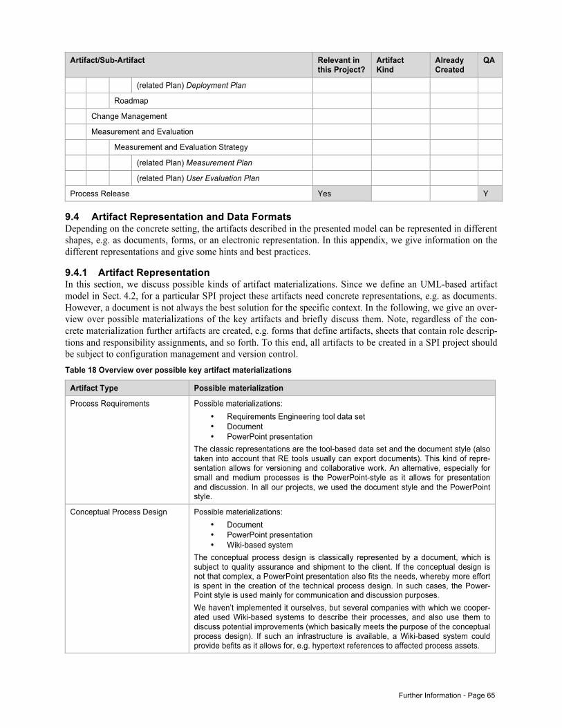
Further Information - Page 65
Artifact/Sub-Artifact Relevant in this Project?
Artifact Kind
Already Created
QA
(related Plan) Deployment Plan
Roadmap
Change Management
Measurement and Evaluation
Measurement and Evaluation Strategy
(related Plan) Measurement Plan
(related Plan) User Evaluation Plan
Process Release Yes Y
9.4 Artifact Representation and Data Formats Depending on the concrete setting, the artifacts described in the presented model can be represented in different shapes, e.g. as documents, forms, or an electronic representation. In this appendix, we give information on the different representations and give some hints and best practices.
9.4.1 Artifact Representation In this section, we discuss possible kinds of artifact materializations. Since we define an UML-based artifact model in Sect. 4.2, for a particular SPI project these artifacts need concrete representations, e.g. as documents. However, a document is not always the best solution for the specific context. In the following, we give an over-view over possible materializations of the key artifacts and briefly discuss them. Note, regardless of the con-crete materialization further artifacts are created, e.g. forms that define artifacts, sheets that contain role descrip-tions and responsibility assignments, and so forth. To this end, all artifacts to be created in a SPI project should be subject to configuration management and version control. Table 18 Overview over possible key artifact materializations
Artifact Type Possible materialization
Process Requirements Possible materializations: • Requirements Engineering tool data set • Document • PowerPoint presentation
The classic representations are the tool-based data set and the document style (also taken into account that RE tools usually can export documents). This kind of repre-sentation allows for versioning and collaborative work. An alternative, especially for small and medium processes is the PowerPoint-style as it allows for presentation and discussion. In all our projects, we used the document style and the PowerPoint style.
Conceptual Process Design Possible materializations: • Document • PowerPoint presentation • Wiki-based system
The conceptual process design is classically represented by a document, which is subject to quality assurance and shipment to the client. If the conceptual design is not that complex, a PowerPoint presentation also fits the needs, whereby more effort is spent in the creation of the technical process design. In such cases, the Power-Point style is used mainly for communication and discussion purposes. We haven’t implemented it ourselves, but several companies with which we cooper-ated used Wiki-based systems to describe their processes, and also use them to discuss potential improvements (which basically meets the purpose of the conceptual process design). If such an infrastructure is available, a Wiki-based system could provide befits as it allows for, e.g. hypertext references to affected process assets.
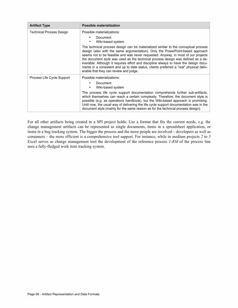
Page 66 - Artifact Representation and Data Formats
Artifact Type Possible materialization
Technical Process Design Possible materializations: • Document • Wiki-based system
The technical process design can be materialized similar to the conceptual process design (also with the same argumentation). Only the PowerPoint-based approach seems not to be feasible and was never requested. Anyway, in most of our projects the document style was used as the technical process design was defined as a de-liverable. Although it requires effort and discipline always to have the design docu-ments in a consistent and up to date status, clients preferred a “real” physical deliv-erable that they can review and judge.
Process Life Cycle Support Possible materializations: • Document • Wiki-based system
The process life cycle support documentation comprehends further sub-artifacts, which themselves can reach a certain complexity. Therefore, the document style is possible (e.g. as operations handbook), but the Wiki-based approach is promising. Until now, the usual way of delivering the life cycle support documentation was in the document style (mainly for the same reason as for the technical process design).
For all other artifacts being created in a SPI project holds: Use a format that fits the current needs, e.g. the change management artifacts can be represented as single documents, items in a spreadsheet application, or items in a bug tracking system. The bigger the process and the more people are involved – developers as well as consumers – the more efficient is a comprehensive tool support. For instance, while in medium projects 2 to 5 Excel serves as change management tool the development of the reference process 1-RM of the process line uses a fully-fledged work item tracking system.
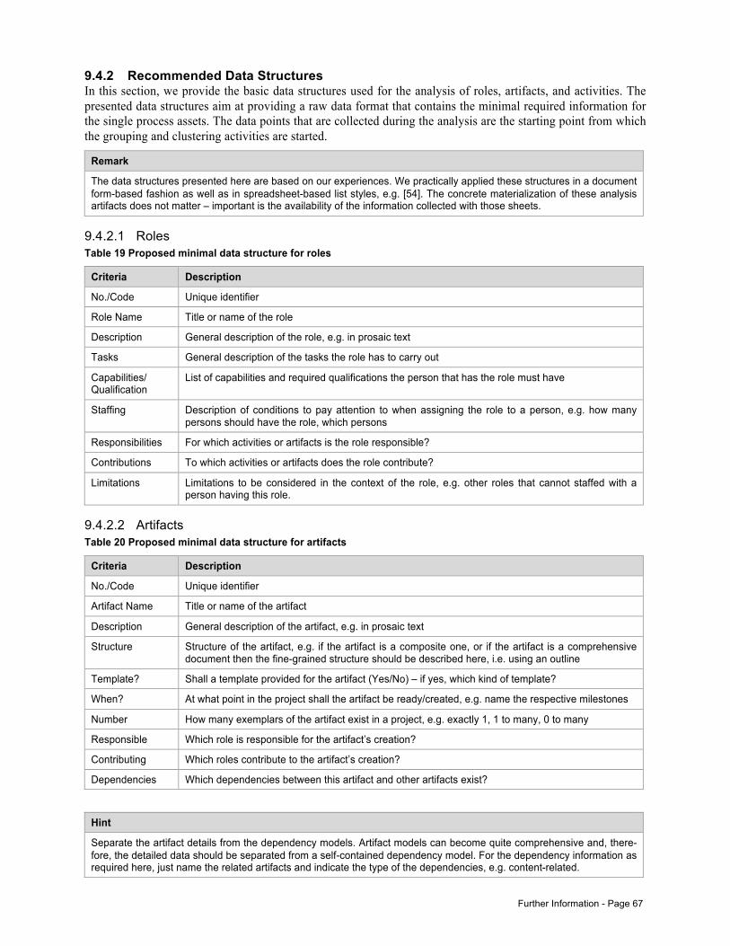
Further Information - Page 67
9.4.2 Recommended Data Structures In this section, we provide the basic data structures used for the analysis of roles, artifacts, and activities. The presented data structures aim at providing a raw data format that contains the minimal required information for the single process assets. The data points that are collected during the analysis are the starting point from which the grouping and clustering activities are started.
Remark
The data structures presented here are based on our experiences. We practically applied these structures in a document form-based fashion as well as in spreadsheet-based list styles, e.g. [54]. The concrete materialization of these analysis artifacts does not matter – important is the availability of the information collected with those sheets.
9.4.2.1 Roles Table 19 Proposed minimal data structure for roles
Criteria Description
No./Code Unique identifier
Role Name Title or name of the role
Description General description of the role, e.g. in prosaic text
Tasks General description of the tasks the role has to carry out
Capabilities/ Qualification
List of capabilities and required qualifications the person that has the role must have
Staffing Description of conditions to pay attention to when assigning the role to a person, e.g. how many persons should have the role, which persons
Responsibilities For which activities or artifacts is the role responsible?
Contributions To which activities or artifacts does the role contribute?
Limitations Limitations to be considered in the context of the role, e.g. other roles that cannot staffed with a person having this role.
9.4.2.2 Artifacts Table 20 Proposed minimal data structure for artifacts
Criteria Description
No./Code Unique identifier
Artifact Name Title or name of the artifact
Description General description of the artifact, e.g. in prosaic text
Structure Structure of the artifact, e.g. if the artifact is a composite one, or if the artifact is a comprehensive document then the fine-grained structure should be described here, i.e. using an outline
Template? Shall a template provided for the artifact (Yes/No) – if yes, which kind of template?
When? At what point in the project shall the artifact be ready/created, e.g. name the respective milestones
Number How many exemplars of the artifact exist in a project, e.g. exactly 1, 1 to many, 0 to many
Responsible Which role is responsible for the artifact’s creation?
Contributing Which roles contribute to the artifact’s creation?
Dependencies Which dependencies between this artifact and other artifacts exist?
Hint
Separate the artifact details from the dependency models. Artifact models can become quite comprehensive and, there-fore, the detailed data should be separated from a self-contained dependency model. For the dependency information as required here, just name the related artifacts and indicate the type of the dependencies, e.g. content-related.
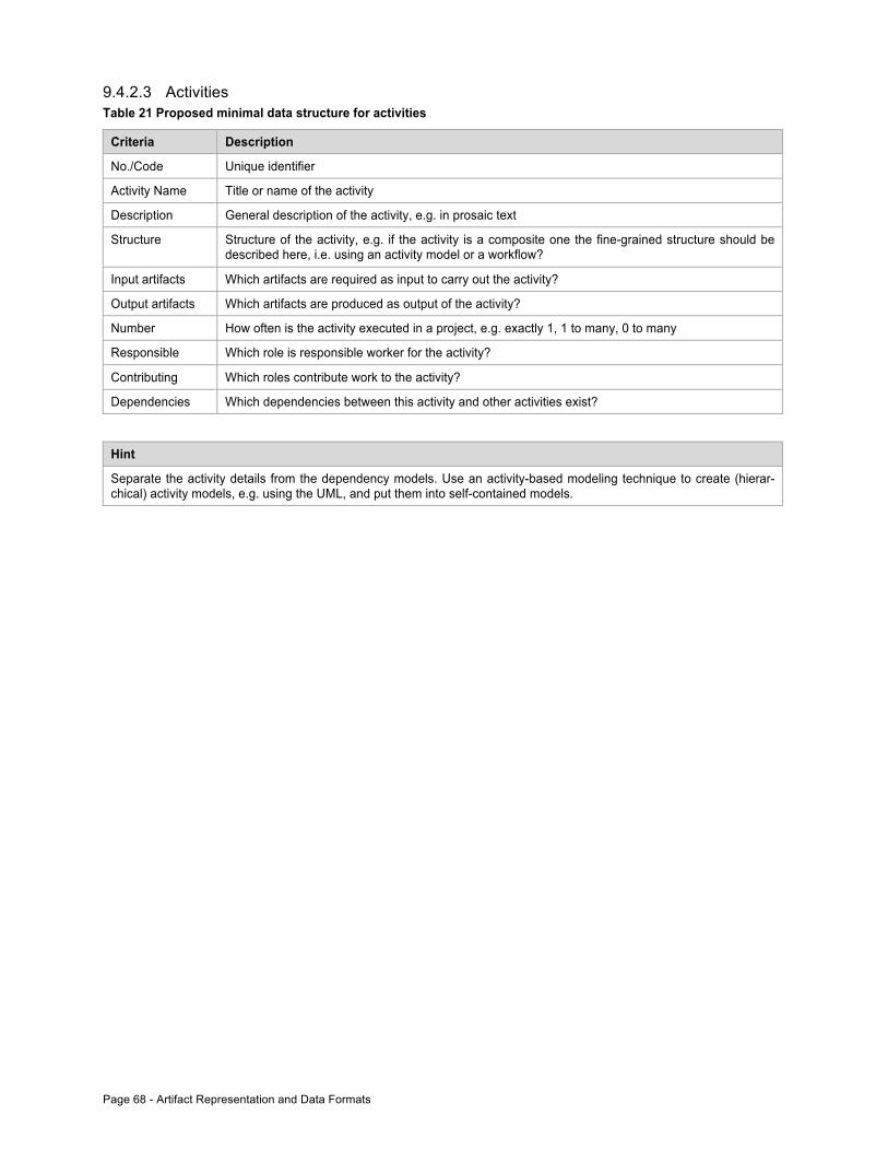
Page 68 - Artifact Representation and Data Formats
9.4.2.3 Activities Table 21 Proposed minimal data structure for activities
Criteria Description
No./Code Unique identifier
Activity Name Title or name of the activity
Description General description of the activity, e.g. in prosaic text
Structure Structure of the activity, e.g. if the activity is a composite one the fine-grained structure should be described here, i.e. using an activity model or a workflow?
Input artifacts Which artifacts are required as input to carry out the activity?
Output artifacts Which artifacts are produced as output of the activity?
Number How often is the activity executed in a project, e.g. exactly 1, 1 to many, 0 to many
Responsible Which role is responsible worker for the activity?
Contributing Which roles contribute work to the activity?
Dependencies Which dependencies between this activity and other activities exist?
Hint
Separate the activity details from the dependency models. Use an activity-based modeling technique to create (hierar-chical) activity models, e.g. using the UML, and put them into self-contained models.
Glossary - Page 69
10 Glossary
CPD Conceptual process design; Sect. 7.1.2
CMMI Capability Maturity Model Integration
ISO 15504 (aka SPICE) – Software Process Improvement and Capability Determination
Process-engineering framework (short: process framework) – According to [56] “a combination of SPMMs, tools, and guidelines” that form the framework in which a software process is analyzed, de-signed, implemented, and deployed.
PLC Process life cycle support; Sect. 7.1.4
PM Project management
PR Process release; Sect. 0
PRQ Process requirements; Sect. 7.1.1
SPI Software process improvement
SPL Software process line
SPLC Software process life cycle model; Sect. 8.1
SPM Software process management
SPMM Software process metamodel, e.g. SPEM, V-Modell XT
TPD Technical process design; Sect. 7.1.3
QA Quality assurance – part of QM, which is instantiated and done in a project context.
QM Quality management
V-Modell XT The German standard IT development process; available online: http://www.v-modell-xt.de (English version available)
11 The ArSPI Model In the following, we present the complete ArSPI model in its UML representation. All model pictures can be downloaded at:
http://www4.in.tum.de/~kuhrmann
In the following, we present the overall model, and the key elements and their relation:
• The overall model • The relation between the conceptual process design and the technical process design • The relation between the process assets and the conceptual process design • The relation between the process assets and the technical process design
11.1 The Overall Model
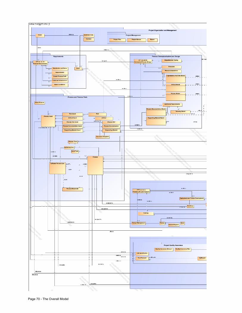
Page 70 - The Overall Model
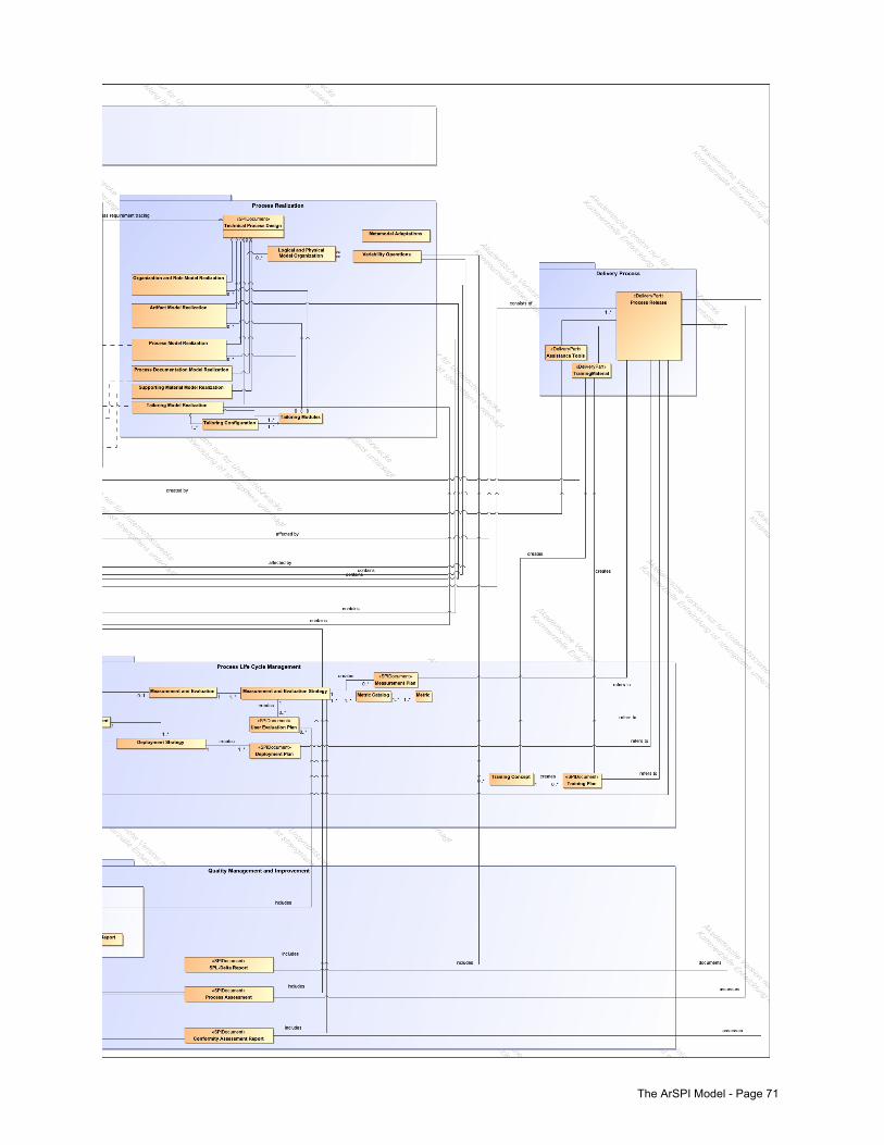
The ArSPI Model - Page 71
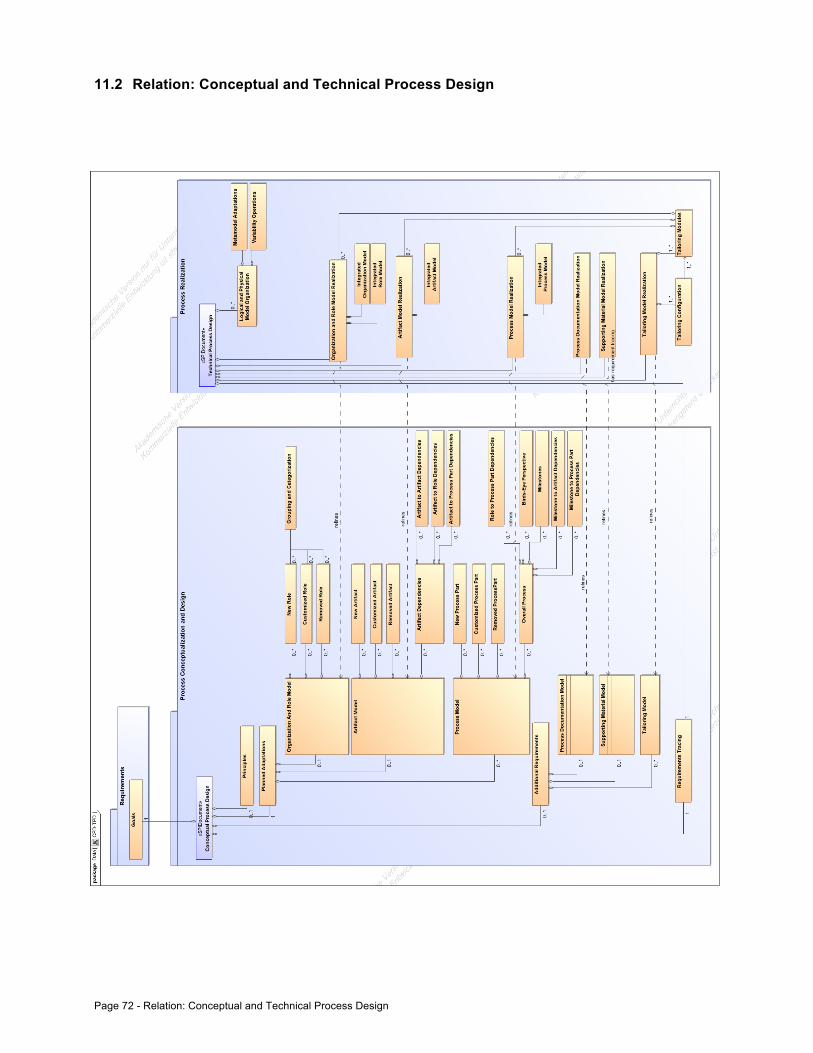
Page 72 - Relation: Conceptual and Technical Process Design
11.2 Relation: Conceptual and Technical Process Design
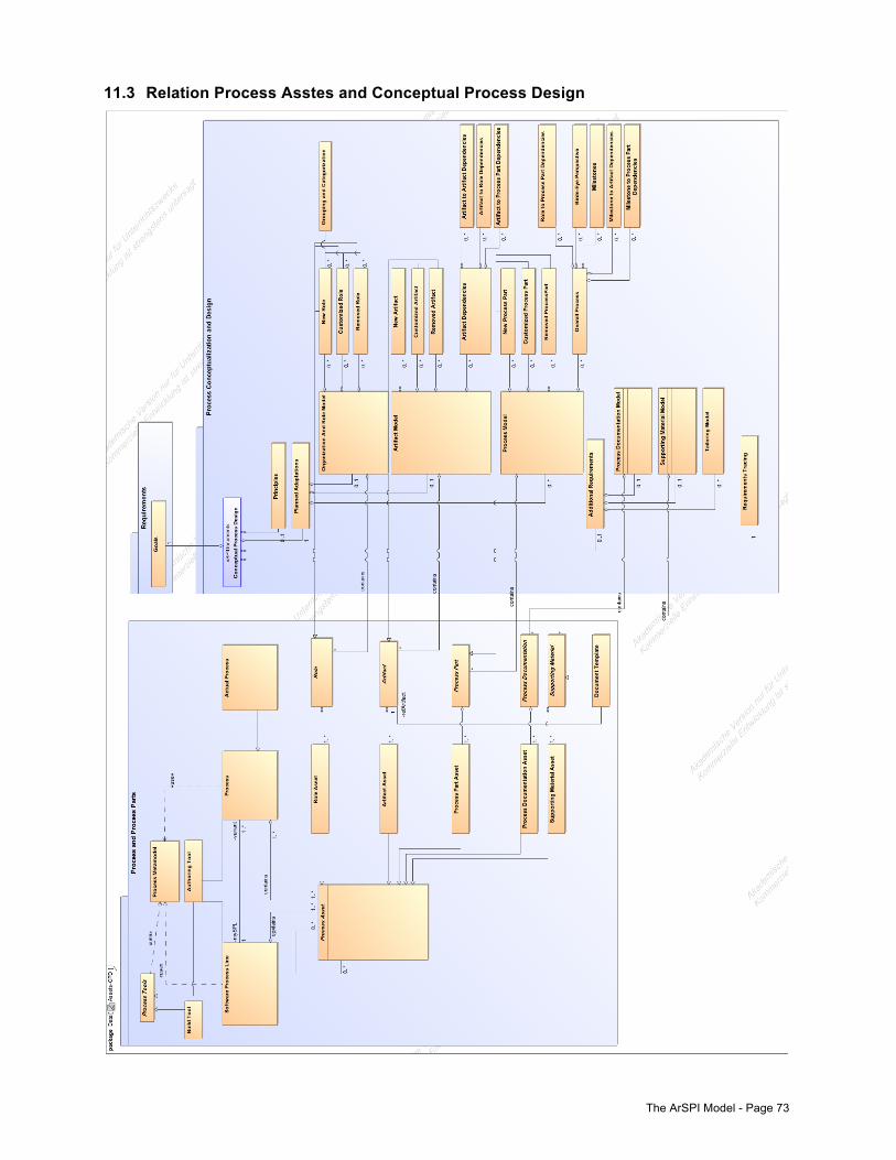
The ArSPI Model - Page 73
11.3 Relation Process Asstes and Conceptual Process Design
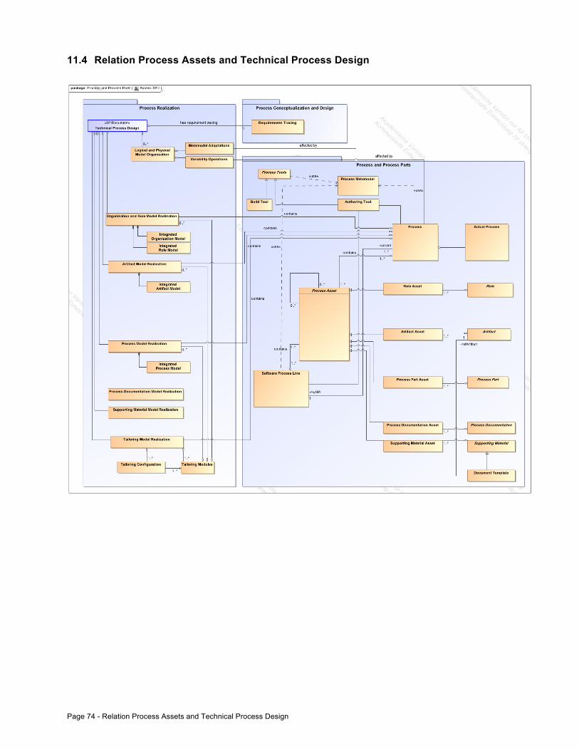
Page 74 - Relation Process Assets and Technical Process Design
11.4 Relation Process Assets and Technical Process Design