Embed Size (px)
Citation preview

ARNOLD GAUGE 9823 Harwood Court
Fairfield, Ohio 45014
Phone: (877) 942-4243
Fax: (877) 942-2877
www.arnoldgauge.com
INSTRUCTIONS
FOR INSTALLING AND USING
MODEL LR
CONTINUOUS GRINDING GAGES
PDF processed with CutePDF evaluation edition www.CutePDF.com
Parts Diagram
Filler Plug Mounting Bracket
Clamp Support Arm
Plunger Spring
Tension Adjustment
Dial Indicator
Plunger Travel
Adjustment
Gauge Frame
Spring Bushings
Caliper
Plunger
Mounting
Bracket
Set Screws
Mounting Bracket
Indicator
Position
Adjustment
Hub Handle

Satisfactory gage performance depends to a great extent upon proper attachment. A solid,
rigid point should be selected on the machine at which the ½-13 socket head cap screw can be
fastened. In those cases where the machine does not present a suitable surface for
attachment, it is preferable to construct a simple bracket to facilitate installation. The bracket
should be rugged, being made from 5/8 x 2 ½” steel bar stock.
Gage set-ups should allow the work piece to traverse through the gaging contacts indicating
not only diameter but taper. This is an advantage where interruptions or part configurations
do not permit traverse grinding. All arrangements are suitable for plunge grinding.
Arnold gages are shipped pre-assembled, allowance being made for shipping limitations.
Attach with a ½-13 socket head cap screw. Where-ever possible the angles shown should be
observed. It is particularly important to keep the gage frame square with the work piece.
Adjustments of the mounting bracket set screws provide a means for perfect alignment of the
gage.
Reversal of the mounting is effected by rotating the lift spring about its anchoring rivet 180
degrees. The gate must be turned end for end in order that the check valve there in will
function to restrict the lifting motion. Re-assembly together with the addition of SAE-20
motor oil restores the unit to proper operation.

STEP 1: Mounting and alignment
Attach mounting bracket to grinder with 1/2-13
socket head cap screw.
Adjust the three set screws with a flat head
screwdriver to properly align the gage with your
workpiece.
STEP 2: Set lifting force
Loosen the flanged jam nut with a 3/4" wrench,
and rotate the spring with a 1/4" hex wrench.
The spring should exert 4-8 ounces (110-220
grams) more than necessary to exactly
counterbalance the gage.
-Not enough force will cause unstable gaging
contact
-Too much force will wear the gage and
workpiece
STEP 3: Set lifting speed
Adjust the lifting speed so the gage raises
smoothly, coming to a soft cushioned stop.
Use a 1/8 hex wrench to adjust the oil metering
screw.
Clockwise = faster
Counterclockwise = slower
-Not enough force will cause longer cycle time
-Too much speed will shock the gage and
cause measurement error.

Step 5
While the gage is supported by the rotating work piece,
the indicator is moved into its operating position by the
associated cam provided for that purpose. It is
generally set with the zero at the top of the dial face,
although this is not absolutely necessary. The indicator
should not revolve more than one revolution during the
grinding cycle for two reasons: to avoid confusion with
which “zero” is at finish size, and to avoid unnecessary
wear and tear of the indicator mechanism.
Step 4
The adjustable caliper is locked into a given setting by
three socket head set screws. To change, loosen these
screws and move to the new position, observing the
graduated scale. Make certain the back contact
engages the body before tightening its locking screw.
Single purpose calipers and spline type calipers do not
require any adjustment and are ready to use as shipped.
Should marking of the work piece occur, lapping slightly
with diamond compound will eliminate this difficulty.
Step 6
Plunger force is established by turning the spring
adjustment clockwise for increased pressure and
counter-clockwise for decreased pressure. Use of the
locking screws will hold the final setting. The plunger
should have about 12 to 16 ounces force with which to
grip the work piece. Softer material will generally
require lighter pressures to avoid burnishing. Excessive
pressure will diminish sensitivity and score the work
piece. The factory has adjusted for average grinding
conditions.
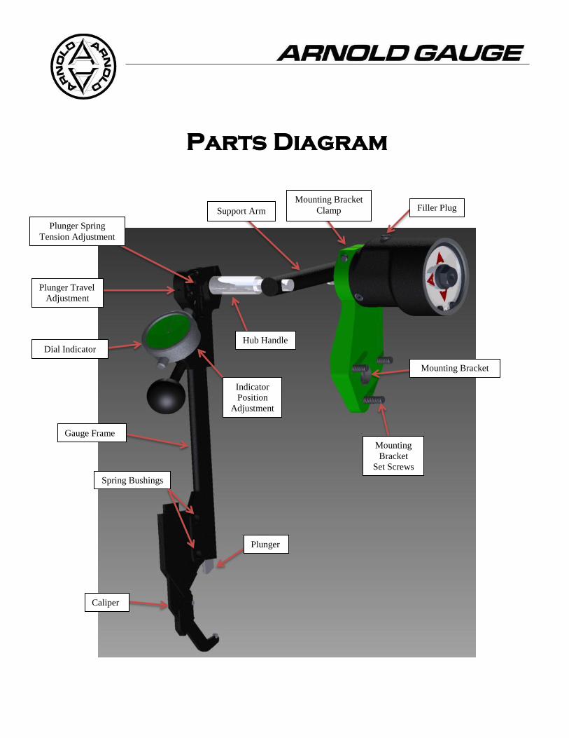
Step 7
Turning the plunger travel adjustment screw will
determine the amount the plunger can move undersize
after the gage has been removed from the work piece.
Generally, it is desirable to confine this travel to
approximately .010”, thus eliminating unnecessary wear
and tear on the indicator. Limited travel will minimize
carrying grinder sludge into the gage frame. Test the
adjustment by pushing the gage on and off the work
piece repeatedly.
HOW TO USE THE GAGE:
Arnold gages are essentially in-process comparators used on external grinders and supported directly by the
work pieces. For this reason these continuous grinding gages are set-up to masters or to work pieces ground
within tolerance. They must be checked occasionally, the frequency dependent upon the closeness of
tolerance. Unlike most comparators, these gages are capable of monitoring continuously not only the
diameter, but roundness, surface condition and often times chatter.
Operation of the gage involves its placement followed by observation of the dial indicator. The indicator hand
will approach size in a clockwise direction coming to zero at its completion. Every effort should be made to
handle the gage with care.
With the gage riding the work piece, the grinder feed rate can be crowded for fast stock removal. Near finish
size, the feed should be slowed down or stopped entirely, allowing the “spring” within the set-up to carry the
operation on down to final size. Temperature build-up within the part must be considered at all times. The
work piece must be allowed to cool sufficiently when approaching finish size in order that the diameter will
round up and a good finish will result. Generally speaking, longer grinding cycles with a generous spark-out
period will produce better results. Out-of-round work pieces will appear as wobble on the dial indicator. Small
flats, chatter, and rough surfaces will reflect as a high frequency flutter. What appears to be erratic gage
behavior is often times only a manifestation of what is actually taking place at the work piece.
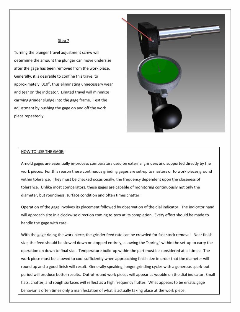
Exchange calipers by driving spring bushings into place.
Set gage frame on protected surface to avoid marring.
NOTE: Holes are deliberately offset to insure proper
assembly.
MAINTENANCE:
Conditions around the grinder are usually wet and dirty owing to the nature of the operation. Arnold gages
must work satisfactorily under these conditions. Successful gaging will therefore depend largely upon how
clean the gages are kept, how they are kept in repair, and what effort is made to prevent breakdowns
beforehand. Gages that are permitted to become dirty will eventually “stick” with grinder sludge. Abused
gages will “stick” from bent and deformed parts. Excessive oiling will only serve to clog the gage and lock up
the indicator. It is THEREFORE ONLY REASONABLE TO – KEEP ARNOLD GAGES CLEAN, PROPERLY ADJUSTED,
AND IN GOOD REPAIR if you expect continuing success with them.
Constantly maintain a good working installation. Keep the gage free of encumbrances such as hoses, splash
guards, and other unnecessary additions. Beware of modifications calculated to improve gage performance
which often produce the opposite result. Consult the factory – let us pass along our recommendations on gage
practice and usage.

SPLINE CALIPERS
For best results re-lap spline calipers on the job.
Use Norbide 220 or 320 grit with oil. Diamond
compound is satisfactory. This will assure
alignment on your machine
1. Substitute indicator contact points, if necessary, to extend gage adjustment. Use points with ball
end.
2. The various screws and nuts on the gage should not be tightened excessively. No benefit
accrues, and often times threads are stripped and adjustments made difficult or impossible.
3. Fine adjustment of “zero” can be made by rotating bezel of indicator.
4. Do not permit gage to rest upside down. Sludge and coolant will drain into gage resulting in
maintenance problems.
5. Taper can be detected by traversing work piece through the gage.
6. Occasionally check adjustments to make certain they are locked firmly into place.
7. Keep set-ups compact and close coupled to minimize deflection and keep arrangement rigid.
8. Dirty Gages are insensitive gages.

JR MOUNTINGTITLEPART NUMBERQTY
Fiber Washer1500312Levelling Bracket Assy1712031Rotor Assy1712051Lift Spring Assy (Standard)*
1712071
Gate Assy1712081Spring Adj. Lock Nut1712091Spring Cover1712121Inner Snap Ring1712191Outer Snap Ring1712211Bearing Support Seal171230*1Rate Adj. Screw1712331Gate Attach. Screw171237**2JR Housing1712381Inner Bearing1712401Outer Bearing1712421Bearing Seal1712432Bearing Support1712471Sector Attachment Screw1715031Oil Filler Assy171235***1Screw Seal171246*2
171209
171221
171212
150031
150031
171207
171219
171243
171240
171247
171203
171243
171242
171237**
171233
171230*
171503
171208
171238
171235***
171205
171246*
*Use 171224 (Heavy-Duty Lift Spring Assy)
or 171224R (Reverse Heavy-Duty Lift Spring Assy)
if using 14" or 16" long support arms or if using a
heavy gage assembly
Use 171207R (Reverse Lift Spring Assy)
if using Reverse JR mounting
If using Reverse JR mounting, 171208 (Gate Assy)
must be mounted 180 degrees
*Add grease on parts 171246 and 171230 to
prevent cutting
**Add silicone on 171237 to prevent leaking
***Add teflon tape on 171235 to prevent leaking
9823 Harwood Court
Fairfield, OH 45014
PH: 513-942-GAGE (4243)
FAX: 513-942-2877
www.arnoldgauge.com
Rev 11-2009
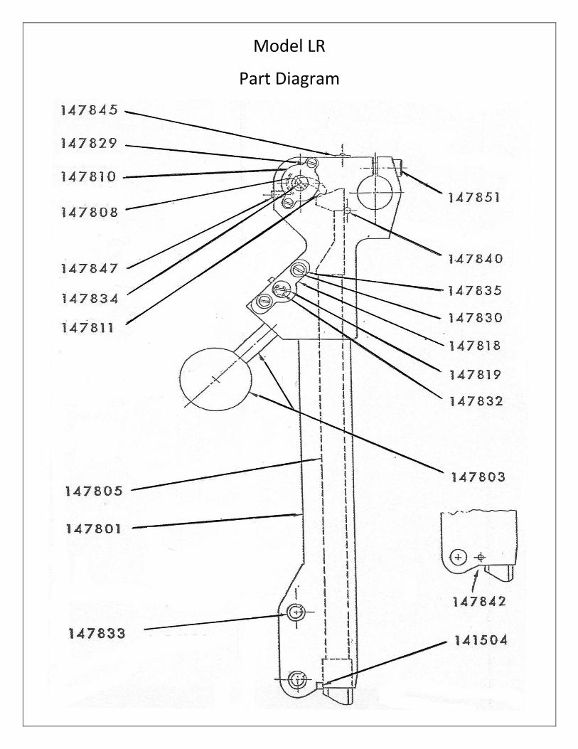
Model LR
Part Diagram

Model LR Grinding Gage
Part Number Description
147801 Main Frame Assembly
147819 Indicator Adjusting Cam and Lock ring Group
147832 Indicator Adjustment Cam locking ring
147840 Plunger Upper Guide Insert
147847 Spring Top Screw (8-32 x3/2 lg. Special)
147851 Hub Clamp Screw (1/4-28 x 5/8 lg.)
147803 Handle Assembly
111401 Handle Ball
111402 Handle Stud 147805 Plunger
148001 Upper Molded Carbide End
148002 Lower Molded carbine End
148003 Plunger Center Section
147808 Plunger Spring and Housing Assembly
147810 Spring Lock Plate and Screw Group
147848 Spring Lock Plate
147829 Spring lock Plate Screw (4-40 x ¼ lg.) (2)
147811 Spring Lever Assembly
147818 Indicator Slide, Screw and Washer Group
147849 Indicator Adjustment Slide
147830 Indicator Clamp Screw ( 8-32 x 5/8 lg.)(2)
147835 Indicator Clamp Screw Washers (#8s Brass)(2)
147833 Caliper Bushing (2)
147834 Spring Level Pin
147842 Lower Bearing Carbide (1/8 Dia. X 5/16 lg.)
147845 Oiler (Drive Type)
Model LR Service Parts
141504 Lower Bearing Carbide (1/8 sq x 5/16 lg.)
145501 Collet, 3/8” Diameter Hole, for attachments
147861 Main Frame Assembly (Collet)
NOTE: UNLESS SPECIFIED, REQUIRED QUANTITY IS ONE EACH.

Adjustable Caliper Parts Diagram

Adjustable Calipers
Part Number Description
152201 Set Screw (10-32 x 1/2 lg. Flat point)
142102 Disc Contact , Tungsten Carbide
3/16” to 1-1/2” Adjustable Caliper
152210 Body Assembly
152211 Slide Assembly
152213 Back Contact Assembly
1” to 3” Adjustable Caliper
152230 Body Assembly
152231 (152278)
Slide Assembly (Flat carbide for crankshaft Grinding)
152233 (152279)
Back Contact Assembly (Flat carbide for crankshaft Grinding)
3” to 5” Adjustable Caliper
152250 Body Assembly
152251 (152281)
Slide Assembly (Flat carbide for crankshaft Grinding)
152253 (152282)
Back Contact Assembly (Flat carbide for Crankshaft Grinding)
5” to 8” Adjustable Caliper
152260 Body Assembly
152261 Slide Assembly
152263
Back Contact Assembly
8” to 12” Adjustable Caliper
152270 Body Assembly
152271 (152287)
Slide Assembly (Flat carbide for crankshaft Grinding)
152273 (152288)
Back Contact Assembly (Flat carbide for Crankshaft Grinding)
Metric Graduated Slide Assemblies (Disk Carbide)
152212 Slide Assembly (6mm-40mm)
152232 Slide Assembly (25mm-75mm)
152252 Slide Assembly (75mm-125mm)
152262 Slide Assembly (125mm-200mm)
152272 Slide Assembly (200mm-300mm)
NOTE: Adjustable calipers and parts are interchangeable on models; L, WF, R, AND LR Gages.

Parts and Service Policy
The Arnold Gauge Company will make every effort to cooperate and assist those responsible for the maintenance of our products. We shall deliver either and/or components with utmost speed and consideration for your needs. All shipments are made F.O.B. Fairfield, Ohio. To promote rapid service, we suggest that whenever possible the model and serial numbers be included in your request. For our part, we will ship stock items within 24 hours of receipt of the order here in Fairfield. Repairs will be shipped within two weeks. Special gages and parts ship as soon as possible. The Arnold Gauge Company Is prepared to repair and service all of our gages using genuine factory parts.


![942 bekey[2]](https://img.pdfslide.us/doc/110x75/54996dd0b479593d4d8b5699/942-bekey2.jpg)