Embed Size (px)
Citation preview
AVIATIONURBAN
OPERATIONS
MULTISERVICE PROCEDURES FORAVIATION URBAN OPERATIONS
FM 3-06.1MCRP 3-35.3ANTTP 3-01.04
AFTTP (I) 3-2.29
APRIL 2001
AIR LAND SEAAPPLICATION
CENTER
ARMY, NAVY, AIR FORCE, MARINE CORPS
MULTISERVICE TACTICS, TECHNIQUES AND PROCEDURES
AIR LAND SEAAPPLICATION
CENTER
DISTRIBUTION RESTRICTION: Approvedfor public release; distribution is unlimited.

FOREWORD
This publication has been prepared under our direction for use by our respectivecommands and other commands as appropriate.
JOHN N. ABRAMS J. E. RHODESGeneral, U.S. Army Lieutenant General, USMCCommanding General Commanding GeneralU.S. Army Training and Doctrine Marine Corps Combat
Command Development Command
B. J. SMITH LANCE L. SMITHRear Admiral, USN Major General, USAFCommander CommanderNavy Warfare Development Headquarters Air Force
Command Doctrine Center
This publication is available on theGeneral Dennis J. Reimer Training
and Doctrine Digital Library atwww.adtdl.army.mil
�
�������
�� �����
������������ ������������������ ������� �������������� ������������� �������� ������ ����������������� ��
� ����������������������� ���������������������������������� �������������� �� ������������������������ �������������� �������� �������� ��������������
���� ���������������������� �������� ������ ���� �������� ��� ����� ���������������� �������������� �������� ������ ���
�������� ������������������������!�������� �������� ������������������� ������ ���
� �� � ��������������������� ������ ���"������ ����������������� #� �� ��������� �������������� ����� ���� ������! ��� ������ ������
����������"������������������ ������ ���� �������������� ��������������� ������
�� �����
������������ ���� ����������������������$������ ���������������"��������"��%������ ��� %!���������� �������� ������ ���
� �������������
�� ������������� �������������� ������� �������� ����� �������������� �������������� �������� ������ ������������ ������������������������!������� �������� �������������������� ������ ����������������� ���������������� ����� ������� ������ ����������������& ������������������� ����������������������������� �� �������� �� ������������%� ���� ������
�� ������������ ��� ���� ����������������� ��� ������ !������ ����������� ������������������ ������ ��������� �����������������������'��������������� ������������������ ��������������������� ��������� �������& ��������������������� ���
�� ������������������
�������������������� ������ ������ �������� ����� ������� ��(�)���!������!������������� ������������������ ����� ������������������� �� ��������������������� ��������������������� ������������������� !�*
�������������� �!���� �� ����������������� �����+��������������+������ �������������� ������������� ��������������� �����, ���������+����� �������������- ������, ��������)�-(,����-��������� ��������� ������!���-���������� ��������� ��-���. ���/0%11%)�
������������ ��������������

��
������ ����������$������, ����!���� �� ������������� ����������+�$������, �����+�$,���������������� ������������� ��������������� ����, ���������2�������+��$������, ����, �����-��� ������, ������$,,-,����-��������� ��������� ������!��������$������, ����������� ����������� ��� ������$,�-���
�����������3�� �!���� �� ������������� ����������+��3�� ��+�3��������������� ������������� ��������������� �����, ���������3�� �4������-��� ������, �������34-,����-��������� ��������� ������!�������������� ������������������ ����������������� �������$#5��)#���-��'�2���������������������� ����������� �������3�6�(���������� ��781�
���� ��������������. ���!���������������� �� ��������� ��������� ���������� ������!������������� ��������������������-��������� ��������� �����!��������. ����������� ����.#��99%9:8�
�� ����������������
�� �����)�-(,%$,,-,%34-,%����. ���- ������,��������.-,�%����5�������������� ����5����,���������� ���������������� ��!��������& ������������� �� ���������� ������������ ����������5��������!������������������������� ������������ �
�� ������������ ���������������������������& ����� ������� ��������� ��� ��,0�� �����;��� ������������������ ��������� ������������������ �������,������������������� � ������ ������ �����������������������& ���������� ����!������� �� ������
� 4���� �������� ���������������� ������ ����������������� ����<� ��� �������� ������������������������������������� ����������� ����� ������� �������� ��������� ������������� �������� ������� �� � ��� ������ !�����������*
���
����
���������� ������������������������������ ������ ���� ����������� �������� �����! �����������"#�#$�#�#�����
������������
�����������%����&����������'(����)�����*�&�'������������ �������+��"������$�� �,-((�&&�,���.��-������! /-�������� �����+�� �������#!����+�������"# �$�#!+����+
�� �
����������*��0�1�����*�&�'������������ ��������!���-(2����,�����3'��.�,4�� �!+���� #����5+!�+� ��������"+ �$�!+��+� �
����!����
6/� �������������������� �������7�����3������8�-&�*����-����� 59���&��� �8�� ��������#�������#+�! 5�������"#�#$�#�+�! 5�:����&� ���((����1��;�<=&���&��;�1;��&
�"��
9� ������ ��������������+� ���3(������9���&��� �8.�� ��������#!������#�� 5 ��������"#�#$����� 5 �:����&�����&(�;������=&���&��;�1;��&
�*
��������������� ��������������
���������������
�������� ������������������� �!"#$���%�"���� �"�$��"��"%&�'�������
������� ��� �����%�"�()�"�*�$�!%+%,"(�%�$�"���� -.��$�#"&�'�������
����������� ��+��/��0��%�!%+%,"(�%�$�"���� �%1("�$&��2" %��),��
��������������� 3%� 4.��$%�)������"�#%�!"#$���%�%�$%���51%,,������"�#%�6�)%&��,�*���
��(��,����
��������������������� ������������� �������� ������ ��������������� ��
�����������������
���%
787���'7�������9 �����������������������������������������������������������������������������������������������+���
3���7��� :'7�'�7//� #��� ���� � �������������������������������������������������������������������������������������� ��0� =��� ����5��� �� ���������������������������������������������������������������������������� ���9� � ���������,�������, ��������� �� ���������������������������������������������� ���7� 5�!� ��4����5(4�>5�!� ��������, ������5(�,� ����������������������� ��;?� )���� ��@��������� ������������������������������������������������������������������������ ��<:� , ������-����� ���������������������������������������������������������������������������� ���A� .����������������� � ����������������������������������������������������������������������� ���B� ���������, ��������� �� ���������������������������������������������������������������� ���
3���7���� ��6���3����7������/� C�'�� ��� �������������������������������������������������������������������������������������� ���0� ��;� ��������������������������������������������������������������������������������������������������� ���9� �������� �������������������������������������������������������������������������������������������� ���7� ,������������ ��������������������������������������������������������������������������������� ��� ?� � ����� ��-����� �������������������������������������������������������������������������� ����:� ���������-����� ��������������������������������������������������������������������������� ����
*
A� C�������, ������� � ������������������������������������������������������������������� ����B� .�������� ��������, ��������� � ������������������������������������������������ ���
3���7����� �=�>3��:�7����:��/� C�'�� ��� ������������������������������������������������������������������������������������� ����0� �������, ��������� �� �������������������������������������������������������������������� ����9� 4������ ������������������������������������������������������������������������������������������� �����7� , �������, ��� ������, �������� �� ������������������������������������ �����?� ��������, ��� ����������������������������������������������������������������������������� �����:� ���%� %2� ����, ������� � ����������������������������������������������������������� �����A� $��������,����������� ��������������� � ����������������������������� �����B� ) ����������������3������� � ���������������������������������������������������� ����;1� 3�����6��� ��-����� ���������������������������������������������������������������������� �����/8��) ��� %4����(������ �� ������������������������������������������������������������� ����//��.�"��%4����(������ �� ��������������������������������������������������������������� �����/0���������� ��������������������������������������������������������������������������������������� �����/9��=�� �����5�������D �����=5D� ����������������������������������������������� ���� /7��������+�������� ����������������������������������������������������������������������� ����;
3���7���' /7��:���7��=:9�7��/� #��� ���� � ������������������������������������������������������������������������������������ �'�0� 4��� �������� � �������������������������������������������������������������������������� �'�9� �������������-��� ����� ��������������������������������������������������������� �'��7� ����������2���������)����������������� ���������������������������������� �'��?� �������$��'��������.����� �� ���� �� ���������������������������������������� �'��:� ������� �>@��� % �������6>@(� ������������������������������������������������ �'�<A� @��� ���C�� �� �������������������������������������������������������������������������� �'�<B� 5�����-�������� � �������������������������������������������������������������������������� �'��1� ,�������� �-� �>.����� ��,���$���� �� ������������������������������������� �'��/8��.�"��%!������������������@�������������6%BC���%/8�
(>�%/8��.%/7��.%/?@��.%/:��.>�%/B������.%//A� ������������������������� �'��//��.�"��%!������������������@�������������,%/98� ������������������ �'��/0��) ��� %!������������������@�������������=%/���=%/4�
�=%:���=%:7��$=%:8��(=%?B-��+=%/3� ����������������������������������� �'� /9�������� ��$ ����������3�����������.�������� ����3�.�� ���� �'�</7��, ����������� �� ������������������������������������������������������������������������ �'���/?��$����� ���@����������� ������������������������������������������������������������� �'���/:��$����� ���-����� ��������������������������������������������������������������������� �'��
���7�!�8�� ������))�"���,�������>.� %,��%) ����������������������������������������������������������/� $���� ����� ��� ��������������������������������������������������������������������������������0� , �����)��'����������������$��������� �����������������������������������9� .����� �������� � �����������������������������������������������������������������������������7� ������ �������������������������������������������������������������������������������������������������?� ����������� ��� ��������������������������������������������������������������������������������:� 4������ ����������������������������������������������������������������������������������������������A� ) ����������������3������� � ��������������������������������������������������������B� ��������������� ������ �����������������������������������������������������������������1� , �������� �� ���������������������������������������������������������������������������������
*�
/8� ��������, ��� ��������������������������������������������������������������������������������//� )���� ��@��������� ������������������������������������������������������������������������/0� 4��� �������� ������@�� ���� �����������������������������������������������/9� , ���������� ������������������������������������������������������������������������������������
���7�!�8�6 ?"��$���$%,,��%�#%���%(���$�"��"0�$2%�6�$$,%)(�#% ����������������������������6�/� �� ��� ����������������������������������������������������������������������������������������������6�0� )�� ����������� ���� ������������������������������������������������������������������6��9� #����� ��������������������������������������������������������������������������������������������6�;
���7�!�8� �.��$�"�) ����������������������������������������������������������������������������������������������/� 5�����2������C �� ��������������������������������������������������������������������������0� $�����'���2$%:?�C '�C>->@>2><� ���������������������������������������������9� ,������$����� �� �����������������������������������������������������������������������������7� E ����-���������'�$����� ���E-�$���2C+%01��2C+%98�
2C+%9/��2C+%90� ������������������������������������������������������������������������������?� �������������(���� ����'����4�������������(4� ������������������:� =����� �����������������������������������������������������������������������������������������������A� 08���,��� � �����������������������������������������������������������������������������������;B� 0?���,��� � �����������������������������������������������������������������������������������;1� 98���,��� � �����������������������������������������������������������������������������������;/8� 78���,��� � ���������������������������������������������������������������������������������<//� /8?���,��� � ��������������������������������������������������������������������������������/0� ) '��� ����������������������������������������������������������������������������������������������/9� $�����>���� �$�����%������A�:0��������?8������� �������������
���7�!�8�! �%�)"��%,��%#"+%�� ����������������������������������������������������������������������������!�/� ���� ����)� ��� �������������������������������������������������������������������������!�0� @���� � ���������������������������������������������������������������������������������������������!�9� ,�������, �������� ���������������� ���������������������������������������!��7� )� ��� �������������������������������������������������������������������������������������������!��
�7�7�7�7���������������������������������������������������������������������������������������������� �%0%�%�#%)�
>=:����9 ����������������������������������������������������������������������������������������������������� >,"))���������/%���������� ��������� � �� �����������������������������������������>,"))���������0%����������-������� �� ���������������������������������������������������>,"))����<
��!78 ���������������������������������������������������������������������������������������������������������������������������
��>��7� ���� =�� ��������������������������������������������������������������������������������������������� �������� ������� �������������������������������������������������������������������������������������� �������� 3��! �' �������������������������������������������������������������������������������������� �������� 5����� ����������������������������������������������������������������������������������������� �������� �������>������� ���������������������������������������������������������������������� �������� )�������� �������������������������������������������������������������������������������� �������� )���� ����������������������������������������������������������������������������������������� �������� , ������ ���������������������������������������������������������������������������������� ����
*��
���� , �� ���, �� ����� ������������������������������������������������������������������ ��������� #������� ������������������������������������������������������������������������������������� ��� ����� �������#������� ���������������������������������������������������������������������� ��� ����� � ���F�G �������������������������������������������������������������������������������������� ���;����� � ���FCG �������������������������������������������������������������������������������������� ���;����� � ���F,G �������������������������������������������������������������������������������������� ���<����� � ���F-G ������������������������������������������������������������������������������������� ��������� � ���F@G �������������������������������������������������������������������������������������� ��������� 2� ����+����, ��� �$������� ����������������������������������������������� ���� ����� 3��! �'�) ������������ ��������������������������������������������������������� ����<� �� +�����2��� �������������������������������������������������������������������������������� �'��� �� C��� ����������� ������������������������������������������������������������������� �'� � �� (�&�����������)��������2��� ������������������������������������������������ �'� � �� �������)��������� ���� ����������������������������������������������������������� �'� � �� )������>-������.����@��������� ���������������������������������������� �'�;� �� = ����.����@��������� ��������������������������������������������������������� �'�<� �� 6��!�� �����������5 !������� ������ �������������������������������� �'���� �� 5 '%- !��6��!��2��������������������� ��������������������������� �'���� �� 5 '%- !������ ������������������������������������������������������������������� �'���!�� , �������+�(2>+�.�(���� ������������@"����� ������������6��!�� ) ��, ������ ����������������������������������������������������������������������������6�;
��6=7� ��� 08���,����� �+�����(������ �� ������������������������������������������������� ���� �� �����������.����� �$��'����$��� ������������������������������������� �'�;� �� .�"��%!����4��� �������� ����������������������������������������������������� �'�� �� �,%/98=>+�4��� �������� ���������������������������������������������������� �'��� �� �,%/98=>+�4��� ������������ ��������������������������������������� �'� � �� ) ��� %!����4��� ��������� ������������������������������������������������� �'��� �� 4�����'���������#������� ��(������� �
C�������� ��� ������������������������������������������������������������������������ �'��� �� $����� �������-����� ���������� ������������������������������������� �'���� �� $����� ������������������-������������ �������������������������� �'�� � �� -����� �$��� ������������������-������������ �������������� �'���� ��� ���� ��������2� ����-������� �������������
����-������������ ����������������������������������������������������������������� �'���!�� 2������� ���� �������������������������������������������������������������������������6����� ��������� ��,����������� ������A�:0����C��
) ��� ������������������������������������������������������������������������������������������� ) ������)����3������� �����������)���� ���
, ������4��������0?%-������(������ � ������������������������������
*���
�������� ������
����� ��������������� ��
"#���$%&��' (� )� �*����"")�+ ��'��'��&�&���&��&�,��*��-��$' � +�+-�*���*
� '����.,����' �$�%�� ����' ��� )� �*�����+��������'���&�' �����'������.��*�,� $*����� �&�
�&�,��*�� �*�',�'��'��&�$�%�� ����' ��� ���&���' ��&&��&���'�� +���+ �����&�,��*�� *$�',����'
$�%�� ����' �/��&$*,�� ���*���/��&����/������./��*,� $*����� �&���0$�,����' ��$�� �'�
� "#���$%&��' �* ��� '��**������&&�+$�' �� +���� .������& ���''#�'�����%��$��*��$�%�� ����' ��1��,��� $'����/��'��'�,���''��2/���'��*�' /��'��3/����'#����' ���������**�����*�� '#������� ���'�4 '��*�5�������$%&��' ��
�������� �����!
,�������(����� ��������� ������!� �������� �������� ������ ������������� ����������� ��� !������������������������������������������ ������!�������������� �� ��� ���������������� ��������� �����!� ��!��������� ����������������� ������������� ��������� ������������������ ������������������ ������ ������������������� �����������
�������� �������������������
,��������! ����������������������� ��������������������������;���������������������������#������������������� ������� ������������ ����������������������� � ��������� ����� �������� ������ �������������� �������� ��������� ��
�������� ���"���������� ��
,��������������������������� ��� ��������������� ��������� ����������� �!�������� ������� ��� ������ �������� ���������������� ��� ��������� �������������������������� ����� �� �������� ������������������� ������������ �����#��������������������� ������������������������ ���������; �������� ������� ����������� ������ ��� ��������� ����������� ������� ������� ������ ���

�>
�������� #$��� ����%�� &%���
,�������. ���� ����� �����������������������������!��� �������� ����#��������������������'������������������ ������� ���� �����'������������������� ������� ������� ��� ������������������� ����� ���� �������������������!��� ���������� ������������� �����������������������'���������������� � ���������� ��� ��������� ���
>
���������������
#����
���������������� ������������������������������������������� !�"""#$��%%����������&������#$�� ����'�����(�������������� �)*���+,�-����.� +,-/����0���������, #$�1%%- -��.%--2!�3%-��!% 4/�����,����������'����� !����
����
#$�5��,- �.�5,-!�/��+�����0���������� ������)�6�������������������� !�""" �)*������)0� �����. � /�� �)*������)0�,�������,���������. �,,/�����
'��&��������7%1%��)(�+����(� �������������������4� ,��1%���%������%�����-7 ,�1%���8 %��,-5,%�������9������' " �����*����,�&�0����.��%'5/������ �):*�����7; "�����9������,�&�0����.'����/������,9)��8; �"���%:������-:������0��&�����������)����.�*�/
������������
������ �:0� �)*���,�&���:)���� �))�����������,�������������. <�6/����""�900����������������%9����� =���$9������������� �<!�"�
#$�1%������� �:0�%�����(�����2���0�,�&�0��������)��,�� �����0���������, �"�="! 66�
�������&����������:��0�����5�����0�%>9�����-���.���5%! /��2?-?���@����""�;9)����A��=����!��""
%������������������������ ��(�2������8
�� �
8�&(������,�&���:)���� �))���3,���8��� �<"�4��*���%������8������������ 8�&���%����������������� �����.8%�� /���������8�%��8� -�2#+�4�1�5�-��8���'������ �����8��������������
����!����
#$���������,������� ������ ���8?�5�������%��������@�����������'��� ���, �,�����)���� ��� ��%����(��&��?�%��� "���'�����(��������������#$�� 3�B-+23B-,5��'�����(��������������#$��� 3,-3,-73B23,-75��%����������+'�������#$�1%��3B2B$3B-- ����0��������, #$�1%��C3B2B,����)0����������4C#$���%- 3,-3,-B53+8��#9�*9����������'1%���%3�%�3�%5��8����0������8�� �+%� 3 �%��'�����(���������6��43,5���8����0������8���� 3<���5C%3 3,-���8����0������8�6�"�%543 ��#9�*9����������'
I-1
Chapter IOVERVIEW
1. Introduction
a. Background. Urban areas generally function as centers of social, economic,industrial, and political power. These areas facilitate formal and informal civilianand military interaction, and can offer ready access to important resources, such aslabor, water, technology, and information. Historically, United States (US) Forceshave operated within, or in close proximity to urban areas. Demographic andpopulation trends indicate that, in the future, a majority of the world’s populationwill reside in urban areas. Trends toward increased urbanization increase thepotential for US forces to operate in urban areas.
b. Doctrine. US Army and US Marine Corps (USMC) doctrine recommendsisolating and bypassing urban areas when possible due to the costs involved.Former Soviet Union doctrine also recommended avoiding large cities in favor ofspeed and maneuver. However, avoiding urban areas does not prevent an adversaryfrom exploiting its defensive advantages. US Air Force (USAF) doctrine maintainsthat airpower’s versatility and responsiveness allows the simultaneous applicationof mass and air maneuver, almost anywhere, from almost any direction. The speed,range, precision weapons, communications, command and control (C2), informationgathering, and transportation capabilities of US military aircraft enable airpower toplay a major, if not decisive, role in urban operations when proper tactics areemployed. This is possible whether aviation operations are conductedindependently, or in conjunction with the operations of friendly ground forces.Operations in Panama City, Baghdad, Mogadishu, Port Au Prince, Sarajevo, andPristina, are a few examples where airpower has been influential in urbanoperations in the past.
c. Urban Considerations. Aviation urban operations can be planned andconducted across the range of military operations. The two dominant characteristicsaffecting aviation urban operations are the existence of manmade construction andthe presence of noncombatants. These operations may be conducted on or againstobjectives on a complex urban topology and its adjacent natural terrain. Thecompressed battlespace in the urban environment creates unique considerations forplanning and conducting aviation operations. These include:
(1) operations in urban canyons,
(2) deconfliction in confined airspace,
(3) restrictive rules of engagement (ROE),
(4) difficulty in threat analysis,
(5) an overload of visual cues,

I-2
(6) the presence of noncombatants,
(7) the potential for collateral damage, and
(8) the increased risk of fratricide.
These considerations and others, as well as some historical lessons will be discussedin this publication.
2. Historical Lessons
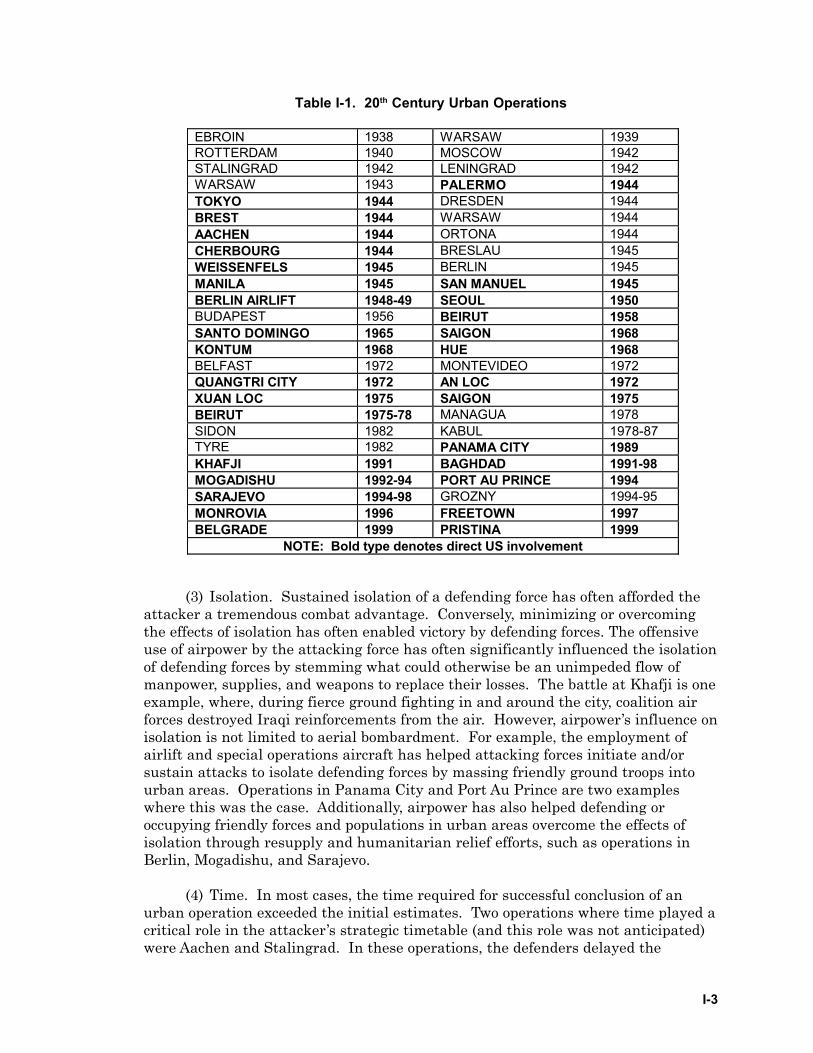
a. Background. Urban operations have been conducted many times in the 20thcentury. See Table I-1. Familiarity with historical lessons is fundamental tounderstanding the difficulties associated with conducting aviation urban operations.In many conflicts throughout the 20th century, aviation (air power) has played animportant and sometimes decisive role in isolating and interdicting the flow of thedefender’s supplies and reinforcements into the urban areas. Advancements inaircraft design and precision munitions in conjunction with specific training forurban operations have increased effectiveness of these operations. For example, theIsrael Defense Forces (IDF) during operations in Beirut, successfully used aviationin a compressed urban battlespace through bombing by fixed-wing aircraft, groundattack by helicopters, and aerial medical evacuation of wounded personnel.
b. Tactical Challenges. Employment of aviation assets in urban operationspresents important tactical challenges. For example, one tactic used successfully byboth attackers and defenders for protection against air and artillery attack has beento keep one’s forces deployed in close proximity to the enemy; thus deterring enemyair or artillery support. This “hugging” tactic, whether by design or as aconsequence of close combat, was often effectively used in many modern urbanbattles.
c. Planning and Conducting Operations. Due to the complexities and increasedchallenges involved in conducting aviation urban operations, the following are someof the important areas of consideration when planning for and conductingoperations in this environment.
(1) Physical limitations. Urban areas offer defenders several advantages.These include the availability of obstacles, cover, concealment, and potentialstrongpoints. City layouts limit traditional methods of military operations. Thevertical nature of this environment and subterranean infrastructure limit line ofsight (LOS).
(2) Surprise. Surprise can help shift the balance of combat power byovercoming other disadvantages and may be critical to success in urbanoperations. Surprise was achieved by the attacker at Aachen and Ban Me Thoutand by the defender at Suez City. Without the element of surprise, friendlyforces may encounter strong, well-prepared defenses without adequate warning.Rapid, accurate, intelligence analysis and dissemination is a key to the element ofsurprise.
I-3
(3) Isolation. Sustained isolation of a defending force has often afforded theattacker a tremendous combat advantage. Conversely, minimizing or overcomingthe effects of isolation has often enabled victory by defending forces. The offensiveuse of airpower by the attacking force has often significantly influenced the isolationof defending forces by stemming what could otherwise be an unimpeded flow ofmanpower, supplies, and weapons to replace their losses. The battle at Khafji is oneexample, where, during fierce ground fighting in and around the city, coalition airforces destroyed Iraqi reinforcements from the air. However, airpower’s influence onisolation is not limited to aerial bombardment. For example, the employment ofairlift and special operations aircraft has helped attacking forces initiate and/orsustain attacks to isolate defending forces by massing friendly ground troops intourban areas. Operations in Panama City and Port Au Prince are two exampleswhere this was the case. Additionally, airpower has also helped defending oroccupying friendly forces and populations in urban areas overcome the effects ofisolation through resupply and humanitarian relief efforts, such as operations inBerlin, Mogadishu, and Sarajevo.
(4) Time. In most cases, the time required for successful conclusion of anurban operation exceeded the initial estimates. Two operations where time played acritical role in the attacker’s strategic timetable (and this role was not anticipated)were Aachen and Stalingrad. In these operations, the defenders delayed the
Table I-1. 20th Century Urban Operations
EBROIN 1938 WARSAW 1939 ROTTERDAM 1940 MOSCOW 1942 STALINGRAD 1942 LENINGRAD 1942 WARSAW 1943 PALERMO 1944 TOKYO 1944 DRESDEN 1944 BREST 1944 WARSAW 1944 AACHEN 1944 ORTONA 1944 CHERBOURG 1944 BRESLAU 1945 WEISSENFELS 1945 BERLIN 1945 MANILA 1945 SAN MANUEL 1945 BERLIN AIRLIFT 1948-49 SEOUL 1950 BUDAPEST 1956 BEIRUT 1958 SANTO DOMINGO 1965 SAIGON 1968 KONTUM 1968 HUE 1968 BELFAST 1972 MONTEVIDEO 1972 QUANGTRI CITY 1972 AN LOC 1972 XUAN LOC 1975 SAIGON 1975 BEIRUT 1975-78 MANAGUA 1978 SIDON 1982 KABUL 1978-87 TYRE 1982 PANAMA CITY 1989 KHAFJI 1991 BAGHDAD 1991-98 MOGADISHU 1992-94 PORT AU PRINCE 1994 SARAJEVO 1994-98 GROZNY 1994-95 MONROVIA 1996 FREETOWN 1997 BELGRADE 1999 PRISTINA 1999
NOTE: Bold type denotes direct US involvement
I-4
attackers longer than was estimated, resulting in the modification of operationalor strategic plans. A well-planned urban defense, even if the defender is isolatedor lacking aviation, armor, or artillery, can consume inordinate amounts of theattacker’s time and resources. This time can permit the defender to reorganize,redeploy, or otherwise effectively marshal resources in other areas.
(5) Intelligence. Many defeats can be attributed to errors in the initialintelligence assessments. The operation at Arnhem in World War II might not haveoccurred if the Allies had been aware of the strength and locations of the Germanforces. At Stalingrad, the attacking Germans were aware of the defending forcesfacing them in the Sixth Army’s zone. However, they incorrectly analyzed the build-up of Soviet forces in other areas; thus resulting in tactical surprise at those points,and diluting their offensive to seize the city. Aviation forces are uniquely suited toprovide timely, thorough, and on-demand intelligence, although the urbanenvironment poses some unique challenges to aerial and space reconnaissance.
(6) Forces. Whether attacking or defending, the size of the force relative tothe enemy’s can be a critical determinant of success or failure. Historically, whenthe attacker outnumbered the defender and/or the quality of defending forces wasinferior, the defeat of the force defending the city was almost certain. The averageattacker to defender ratio in the battles referenced in Table I-1 was four-to-one.Nevertheless, regardless of the size or quality of the defensive forces, the defendercan exact enormous costs on the attacker in time, resources, and casualties. As wasseen at Khorramshahr, the defensive Iranian forces, which were outnumbered fourto one, still held the city for approximately twenty-six days. Another considerationfor both attacker and defender is the inversely proportional relationship betweenforce strength and combat duration. Historically, the stronger the attacker, theshorter the duration of the fight. Aircraft and their unique capabilities provide asignificant force multiplier to either an attacker or defender.
(7) Command, Control, and Communications (C3). C3 is often difficult inthe urban environment. In particular, controlling airspace and air to groundcoordination may be hampered by physical and technical limitations. The urbanenvironment may adversely affect friendly-force communications, with LOScommunications severely limited at times. Effective communications requiresplanning and clear orders.
(a) Planning must address redundant and alternate means ofcommunications. Visual signaling, while difficult, has proven to be effective whenother means of communication are unavailable. The use of commercial telephonesystems or landlines may be also appropriate, but are susceptible to damage,sabotage, and monitoring. Airborne platforms or rooftop retransmission systemscan help alleviate these problems by providing the “high ground” forcommunications relay. The IDF for example, employed unmanned aerial vehiclesas retransmission platforms during the War in Lebanon (1982) with considerablesuccess. In addition to enhancing operations by serving as communicationsrelays, airborne platforms may also provide commanders real or near-real timeintelligence.
I-5
(b) There is always the possibility some subordinate units may be out ofcontact with higher headquarters during much of their mission execution.Therefore, clear orders to subordinate commands, and a thorough understandingof the commander’s intent is essential in helping subordinates understand thelarger context of their actions. This allows them to exercise judgement andinitiative When situations change, making a task obsolete, an understanding ofintent is more lasting and continues to guide subordinate commanders’ actions.General Chuikov of the 62nd Russian Army summed up the concept ofcommander’s intent when speaking of the battle of Stalingrad: “Fighting in acity…is much more involved than fighting in the field. Here, the ‘big chiefs’ havepractically no influence on the officers and squad leaders commanding units andsubunits and into those of the soldiers themselves.”
(8) Weather. Weather may adversely affect aviation operations. Over-reliance on aviation forces may render a force, particularly in the high intensityenvironment of urban combat, susceptible to the uncertainties of weather. In thebattle for Hue City for example, US Marines were unable to effectively employaviation because of low cloud ceilings. Consequently, only one flight of A-4s was ableto employ ordnance in support of the Marines fighting in Hue City during the entirebattle.
(9) Logistics and medical. Urban operations require a responsive logisticalsupport system. Of particular importance is a responsive and robust treatmentand evacuation plan for casualties. To meet casualty and evacuation needs, planto establish aid stations and landing zones as far forward as the situation allows.
(10) ROE. Because aviation urban operations normally pose a high risk ofcivilian collateral damage and fratricide, operations-specific ROE must be craftedcarefully to allow flexibility in fulfillment of the mission. At the same time, ROEmust limit the danger to noncombatants and friendly forces. Because this is sucha crucial issue in the context of urban operations, some historical examples areinstructive.
(a) Manila–1945. Before the battle of Manila in 1945, GeneralMacArthur prohibited aerial bombardment. “The inaccuracy of this type ofbombardment would result beyond question in the death of thousands of innocentcivilians.” He further confined artillery support to observed fire on confirmedpoint targets. However, the artillery restrictions were removed after the firstfew days because of growing US casualties. Furthermore, in apparent disregardfor the ROE, cases of air bombardment and strafing in support of US forcesoccurred in the latter stages of the battle. During this operation, much of the citywas destroyed, or damaged and an estimated 100,000 civilians died.
(b) Seoul–1950. At the outset of the battle, US Marines entered the fightunder very restrictive ROE. Both damage to the city and civilian casualties wereto be held to a minimum. There was to be no close air support (CAS) at all.However, this restriction was lifted in the face of heavy enemy opposition. In theaftermath of the US victory over the defending North Korean forces, 65% of thecity was destroyed and thousands of South Korean civilians were killed.
I-6
(c) Hue City–1968. As US Marines entered Hue City in 1968, the use ofheavy artillery, bombs, and napalm was prohibited. The Army of the Republic ofVietnam corps commander’s request to spare civilians and reduce destruction tothe historic city drove these restrictions. However, as the battle’s progressslowed with significant US Marine casualties, this policy was abandoned andartillery and tanks became a crucial factor in the ultimate success of the battle.In the aftermath of the US victory over the defending North Vietnamese forces,“the estimates tallied ten thousand houses either destroyed or damaged, roughlyforty percent of the city.”
3. Political and Civilian Considerations
a. Collateral Damage. One of the risks in urban operations is the possibilityof widespread collateral damage. While this damage is unintended, the resultingimages of destroyed homes, damaged churches, and injured civilian casualtiesmay have severe operational consequences. This damage is exacerbated by worldwide media reports and enemy attempts to characterize such damage as unlawful.These media reports and claims may affect strategic decision making and lead tothe loss of international and public support. Commanders and planning staffsmust keep these considerations in mind at all times when planning or conductingurban aviation operations. One of the ways in which these issues can be managedis through the careful drafting and management of ROE. However, paramount tothe drafting of these ROE is the need to emphasize the right and obligation ofself-defense, force protection, and military necessity.
b. Military/Civilian Interaction. During urban aviation operations, US forcesshould expect that many civilians and civilian objects would be intermingled withmilitary objectives. Some civilians will pose risks because they may be hostile toUS Forces. This may involve civilians committing hostile acts against US orfriendly forces. On the other hand, the majority of civilians will act strictly inaccordance with their status as non-combatants. Non-combatants should beprotected and respected at all times. Therefore, efforts must be made to protectnon-combatants and civilian objects, which by definition are not militaryobjectives. Military objectives are those objects, which by their nature, location,purpose, or use effectively contribute to the enemy’s war fighting or warsustaining capability. However, the will of the population can be targeted by non-violent measures including offensive information operations (IO). IO canpersuade civilians to avoid any involvement in combat operations. IO can alsoinform non-combatants of the likely location of combat operations. Thisinformation assists them in avoiding any accidental involvement, and inminimizing the likelihood of incidental injuries. However, these kinds of IOshould be consistent with operations security (OPSEC) requirements and fullyintegrated with other IO actions.
c. Post-Hostilities Support. After hostilities cease, military forces may berequired under international law to take on the burden of providing support tothe civilian population in any occupied territory until civilian authority isrestored. Accordingly, commanders must keep in mind that destruction ofessential urban infrastructure can complicate this post combat transition period.Therefore, air planners and commanders conducting aviation urban operationsmust be mindful of all the issues associated with civilian presence.
I-7
4. Law of War (LOW)/Law of Armed Conflict (LOAC)
It is US policy that our forces will abide by LOW/LOAC in all their militaryoperations, no matter how characterized. Urban aviation operations present uniquechallenges, but these too must be conducted in compliance with LOW/LOAC.Commanders and planners must seek the advice of judge advocates at all stages ofplanning to ensure compliance with LOW/LOAC. The two most fundamental andimportant LOW/LOAC concepts are distinction and proportionality.
a. Distinction.
(1) The concept of distinction requires that combatants make every effort todistinguish between military targets and civilian persons or objects. Theprinciple of distinction prohibits intentional attacks on non-combatants or non-military objects. Urban operations require accurate targeting, precision weapons,and realistic training to distinguish successfully between military and civiliantargets.
(2) It is extremely important to distinguish between non-combatants andcombatants. This task can be greatly complicated by the urban environment.Valid military targets or combatants belong to any of the following categories:
(a) members of armed forces,
(b) members of organized militia,
(c) members of resistance movements,
(d) inhabitants of a non-occupied area who take up arms on theapproach of the attacking force,
(e) any civilian who actively poses a direct threat to US forces,
(f) any structure that produces services or warfighting equipment forthe fighting force.
(3) In urban areas, it is often impossible to distinguish adequately betweencombatants and non-combatants or between military targets and civilian objects.LOW/LOAC attempts to ameliorate this dilemma by requiring defending forces toremove the civilian population from the vicinity of military objectives and not tolocate military objectives within or near densely populated areas. Althoughstrictly prohibited by LOW/LOAC, recent experience demonstrates thatdefenders may attempt to render military forces and objectives immune fromattack by mixing their soldiers among non-combatants and using civilianstructures for overtly military purposes. A failure by an adversary to adequatelysafeguard the civilian population does not relieve the attacking commander fromhis obligation to consider civilian collateral damage and injury—any attack muststill be proportionate.
I-8
(4) US forces will face similar dilemmas in future operations. When anunscrupulous enemy uses members of the civilian population as “human shields”,US forces are under no legal obligation to assume all responsibility for theirsafety, nor to place US lives at undue risk. While US forces may attack lawfultargets consistent with the principle of proportionality, the enemy may exploitcivilian casualties resulting from their use of human shields. Therefore,commanders should be prepared to provide information to counter enemymisinformation.
b. Proportionality.
(1) The concept of proportionality requires that any application of combatpower against a lawful military target and any resulting damage to noncombatantlife and/or property not be disproportionate to the military advantage anticipated.For example, under most circumstances leveling an entire city block to kill a singlesniper is disproportionate.
(2) The concept of proportionality as applied to the high population densityurban environment implies the need for weapons with precise and controllableeffects. Particularly in the urban environment, excessive weapons effects can resultin disproportionate civilian collateral damage.
5. Rules of Engagement
a. Background. Drafting and implementing ROE is a challenging but vital issuewhen planning and executing urban operations. As in any operation, ROE must beliberal enough to allow commanders operational flexibility while ensuring friendlyforces stay within the mission’s legal, political, and operational boundaries.Although tension exists between operational efficiency and necessary constraints inall ROE, the close proximity and intermingling of civilian persons and objects in theurban combat environment greatly magnifies this tension. When drafting air ROE,this problem is even more acute. Careful consideration must be given to weaponsystem capabilities and C3 assets when crafting air ROE for the urbanenvironment. The degree of positive control of air assets and surety of targetidentification that is both desirable and possible must be carefully considered.
b. Developing ROE. During planning, ROE must be carefully drafted andthoroughly reviewed in the context of scenarios likely to be encountered by friendlyforces—“chair flying” and “what-iffing” is essential at this time. Operationalplanners should seek guidance and advice from legal and civil affairs (CA) personnelto ensure proposed ROE are consistent with LOW/LOAC, national directives, andthe mission’s political mandate. During deployment and execution, commandersmust continually evaluate the ROE and make recommendations for modifications asrequired by mission exigencies. The ROE must be practical, realistic, enforceable,flexible, and clearly stated. Chairman of the Joint Chiefs of Staff (CJCS) standingROE (SROE) found in CJCS Instruction (CJCSI) 3121.01A, and other applicabletheater ROE must be analyzed and incorporated during planning.

I-9
c. ROE Guidance. LOW/LOAC and the SROE provide authoritative guidancewhen drafting operation-specific ROE. With SROE, a system is in place to ensureauthoritative ROE guidance at all times, and to develop mission specific rules.Units must ensure that the ROE are available and conduct periodic ROE training.
d. Publish and disseminate ROE to all levels. Commanders must ensuretraining facilitates a thorough understanding of the ROE by all members of theforce. When the ROE changes, there must be a system established to ensure thechanges are disseminated and implemented. Mission rehearsals should includeROE exercises during which individuals apply the ROE in realistic situations.Remember, failure to comply with ROE is punishable under the uniform code ofmilitary justice (UCMJ) and may in extreme instances constitute a war crime, socommanders have a moral obligation to ensure all their personnel are thoroughlyfamiliar with mission ROE.
6. Collateral Damage
Collateral damage is the unavoidable or unplanned damage to civilianpersonnel or property resulting from an attack on a military target. An importantfact to keep in mind is that civilian collateral damage is not illegal under LOW/LOAC; excessive civilian collateral damage is. Generally, the incidental loss ofcivilian life or damage to civilian property must not be excessive relative to expectedmilitary damage to be gained from the attack. This is the concept of proportionalityin military attacks. During urban operations, civilian collateral damage may besignificant, and the goal should be to minimize collateral damage and the inherentrisk to non-combatants to the greatest extent possible under the circumstances. Therisk to non-combatants can be mitigated by:
a. appropriate weapon selection,
b. carefully drafted ROE,
c. positive tactical control of offensive air assets, thorough training in urbantactics,
d. moving non-combatants to a safer location whenever possible.
7. Fratricide Prevention
a. Background. Fratricide is the employment of friendly weapons andmunitions with the intent to kill the enemy or destroy his equipment or facilities,which results in unforeseen and unintentional deaths or injury to friendlypersonnel. Fratricide prevention is a matter of concern in all operations. Inurban operations, the characteristics of the terrain create an environment posingadditional challenges. The challenge is minimizing fratricide withoutunreasonably restricting the friendly force’s ability to accomplish the mission.Reducing fratricide requires accurate information pertaining to the location offriendly, neutral, and hostile personnel. This is facilitated through our training,doctrine, tactics, techniques, and procedures (TTP), C3, and sensor employment.
I-10
b. Fratricide Potential. Urban terrain increases the potential for fratricidebecause of the likelihood of close quarters, location and identification (ID)problems, and unintentional secondary weapons effects. During operations inPanama City in Operation JUST CAUSE, infantry units operating in limitedvisibility participated in a coordinated attack with aviation assets. Smokeresulting from preparatory fires began to obscure much of the area.Consequently, the fire control officer of an AC-130 aircraft switched from the low-light level television (LLLTV) to the infrared (IR) sensor. This improved thegunship’s acquisition capability, but the gated laser intensifier (GLINT) tape onfriendly forces was not visible in the thermal sensor. In the course of orbiting theobjective, the gunner’s orientation of the perimeter became confused. Withoutthe confirmation of the GLINT tape, he acquired a friendly vehicle outside theposition and reported it inside the position. In accordance with the fire supportcoordination measures, the gunship was cleared to engage. Mistaking thefriendly fire for enemy mortar fire, the ground unit suffered several casualtiesbefore transmitting the appropriate alarm. In many ways, this incidentreinforces the need for thoroughly planned and executed ROE in an urbanenvironment to prevent fratricide.
c. Recognizing Friendly Forces. Aviation units must know the locations offriendly ground forces. In Operation JUST CAUSE, units providing fire supportwere informed that another unit had cleared a building to the second floor. In fact,the unit had cleared to the tenth floor and was still conducting operations in thebuilding. Supporting units, observing fire and protruding weapons begansuppressive fires. This drew return fire from the friendly unit in the building forseveral seconds. All units must have standardized, clearly understood proceduresfor marking cleared rooms, floors, and buildings in an urban area. These proceduresmust be practiced and discernible even in periods of limited visibility so friendlyaviation units will recognize them.
8. Training Considerations
a. Background. Aviation missions cross the spectrum of operations. Even abenign environment, such as disaster relief or civilian assistance requires focusedtraining to minimize mission risks. Baseline training requirements must addressnavigating on urban terrain. It must also address locating and evaluating dropzones (DZ), locating and evaluating landing zones/pickup zones (LZ/PZ), and safelynegotiating manmade obstacles during a confined area takeoff, or landing.
b. Training Programs. Frequent, realistic training is required to overcome thedifficulties associated with aviation urban operations. This environment requiresachieving and maintaining a high degree of aircrew proficiency. The following areasshould be included in unit training programs:
(1) centralized control, decentralized execution,
(2) application of ROE,
(3) low level flight and navigation,
I-11
(4) night operations,
(5) and live fire training exercises focused on target ID, terminal control, andfratricide prevention.
c. Video and simulation. These aids can enhance planning. Available sourcesand types of video simulation vary. Video footage may augment informationregarding hazards, lighting, and human intelligence (HUMINT). The capability to“fly” a route in planning and/or rehearsal with a video or computer simulationprovides advantages in mission planning and execution. Check with the militaryinstallation or urban training facility manager to determine a site’s availability andcapability.
II-1
Chapter IIURBAN CHARACTERISTICS
1. Background
a. Urban Characteristics. The phrases “urban terrain”, “urban areas”, and“built-up areas”, refer to concentrations of manmade structures and associatedpopulation that alter the natural landscape. The characteristics of the urbanenvironment are important to identify because they influence operations. Aircrewand mission planners must establish order and purpose from the apparent chaos ofan urban area. These areas range from old to new, large to small, and containpopulations from a few thousand to millions. Planners must make sense of thisenvironment for successful planning.
b. Common Characteristics. Understanding the common characteristics isimportant to planning. These characteristics include size, patterns, populationdensity, structural density, and building construction. One of the most significantcharacteristics affecting urban operations is the structural density - how close thebuildings are to each other. Generally, population density is directly proportional tostructural density except in cities where most of the people live in the suburbs oroutskirts. When planning urban operations, the general disposition and attitude ofthe local population are integral to assessments regarding the population density.As experienced in Somalia, crowds can gather quickly and may interfere withoperations.
2. Size
The following categories commonly are used for classifying the size of urbanareas.
a. Villages. Population less than 3,000.
b. Towns and small cities (not part of a major urban complex). Population 3,000to 100,000.
c. Large cities with associated urban sprawl. Population 100,000 to themillions. Covers hundreds of square kilometers.
d. Strip areas. Urban areas built along roads connecting towns or cities.
3. Patterns
a. Urban Patterns. Urban patterns reflect the nature of the surrounding terrainand the relationships between different areas. Classifying urban areas intopatterns aids in navigation, route and LZ selection, and observation techniques.The following patterns represent the common classification patterns.
II-2
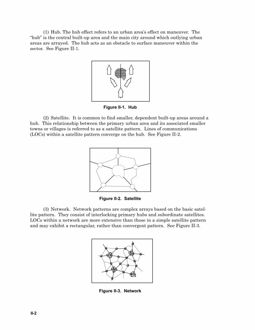
(1) Hub. The hub effect refers to an urban area’s effect on maneuver. The“hub” is the central built-up area and the main city around which outlying urbanareas are arrayed. The hub acts as an obstacle to surface maneuver within thesector. See Figure II-1.
Figure II-1. Hub
(2) Satellite. It is common to find smaller, dependent built-up areas around ahub. This relationship between the primary urban area and its associated smallertowns or villages is referred to as a satellite pattern. Lines of communications(LOCs) within a satellite pattern converge on the hub. See Figure II-2.
Figure II-2. Satellite
(3) Network. Network patterns are complex arrays based on the basic satel-lite pattern. They consist of interlocking primary hubs and subordinate satellites.LOCs within a network are more extensive than those in a simple satellite patternand may exhibit a rectangular, rather than convergent pattern. See Figure II-3.
Figure II-3. Network

II-3
(4) Linear. Built-up areas often follow a linear feature or LOC. These built-up areas are commonly found along interconnecting LOCs within a satellite ornetwork pattern. Buildings extending along major and urban strips or along thebanks of a river or along a coastline are also examples of linear patterns. See FigureII-4.
Figure II-4. Linear
(5) Segment or Pie Slice. When an urban pattern is divided by a dominantnatural or manmade terrain feature, it creates a segmented pattern. Rivers, canals,major roadways, or railways can create a division of the urban area or pattern. Ifthese features converge within the hub or urban pattern, it can create multiplesegments or “pie slice” characteristics. See Figure II-5.
GREEN RIVER
BLUE RIVER
BLUE RIVER
Figure II-5. Segment/Pie Slice
b. Street Patterns. Another common set of patterns in urban areas is streetpatterns. Streets vary in pattern and in width. Outside the US, street widths varyfrom 7 to 15 meters while boulevards range from 25 to 50 meters. In the US, streetwidths normally range from 15 to 25 meters. The following represent commonstreet classifications.
(1) Rectangular. Streets are grid-like in pattern, with parallel streetsintersected by perpendicular streets. See Figure II-6.
Figure II-6. Rectangular
II-4
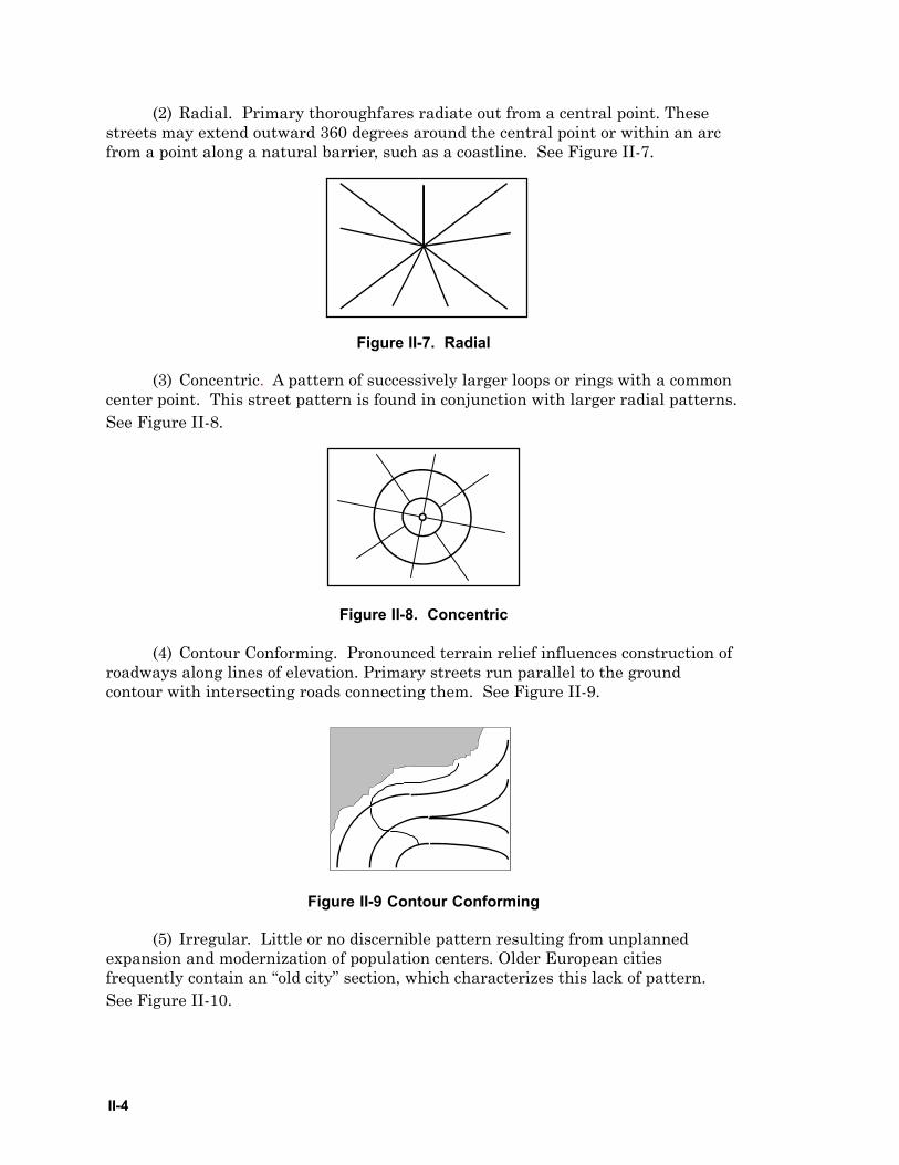
(2) Radial. Primary thoroughfares radiate out from a central point. Thesestreets may extend outward 360 degrees around the central point or within an arcfrom a point along a natural barrier, such as a coastline. See Figure II-7.
Figure II-7. Radial
(3) Concentric. A pattern of successively larger loops or rings with a commoncenter point. This street pattern is found in conjunction with larger radial patterns.See Figure II-8.
Figure II-8. Concentric
(4) Contour Conforming. Pronounced terrain relief influences construction ofroadways along lines of elevation. Primary streets run parallel to the groundcontour with intersecting roads connecting them. See Figure II-9.
Figure II-9 Contour Conforming
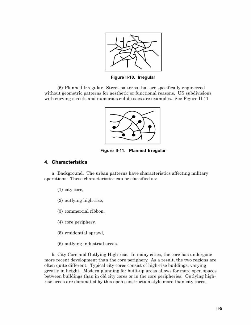
(5) Irregular. Little or no discernible pattern resulting from unplannedexpansion and modernization of population centers. Older European citiesfrequently contain an “old city” section, which characterizes this lack of pattern.See Figure II-10.
II-5
Figure II-10. Irregular
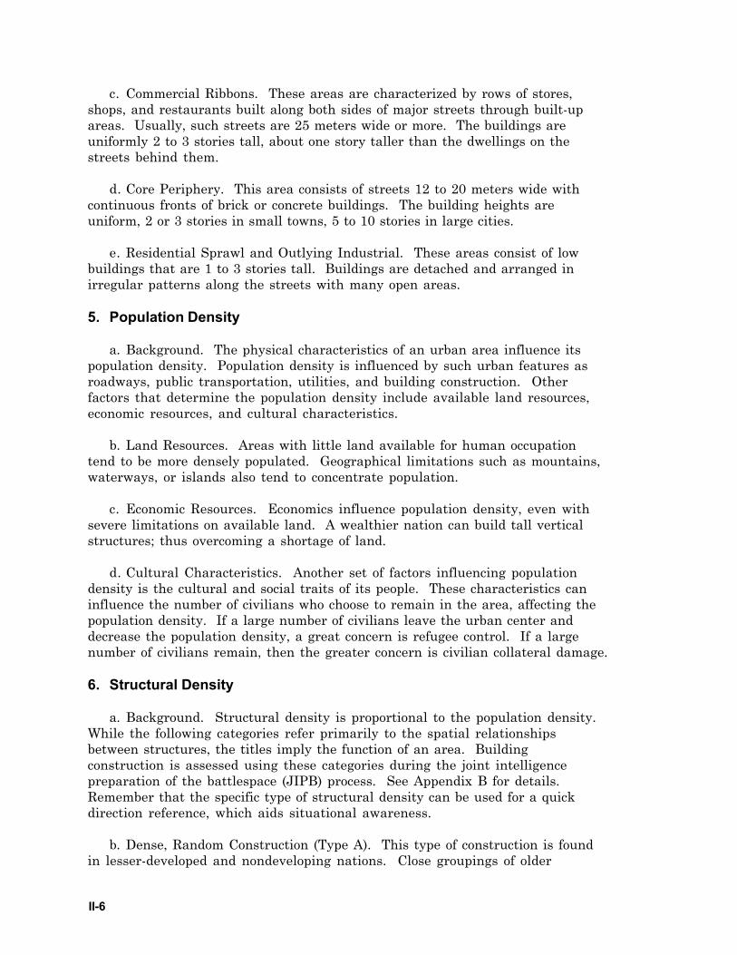
(6) Planned Irregular. Street patterns that are specifically engineeredwithout geometric patterns for aesthetic or functional reasons. US subdivisionswith curving streets and numerous cul-de-sacs are examples. See Figure II-11.
Figure II-11. Planned Irregular
4. Characteristics
a. Background. The urban patterns have characteristics affecting militaryoperations. These characteristics can be classified as:
(1) city core,
(2) outlying high-rise,
(3) commercial ribbon,
(4) core periphery,
(5) residential sprawl,
(6) outlying industrial areas.
b. City Core and Outlying High-rise. In many cities, the core has undergonemore recent development than the core periphery. As a result, the two regions areoften quite different. Typical city cores consist of high-rise buildings, varyinggreatly in height. Modern planning for built-up areas allows for more open spacesbetween buildings than in old city cores or in the core peripheries. Outlying high-rise areas are dominated by this open construction style more than city cores.
II-6
c. Commercial Ribbons. These areas are characterized by rows of stores,shops, and restaurants built along both sides of major streets through built-upareas. Usually, such streets are 25 meters wide or more. The buildings areuniformly 2 to 3 stories tall, about one story taller than the dwellings on thestreets behind them.
d. Core Periphery. This area consists of streets 12 to 20 meters wide withcontinuous fronts of brick or concrete buildings. The building heights areuniform, 2 or 3 stories in small towns, 5 to 10 stories in large cities.
e. Residential Sprawl and Outlying Industrial. These areas consist of lowbuildings that are 1 to 3 stories tall. Buildings are detached and arranged inirregular patterns along the streets with many open areas.
5. Population Density
a. Background. The physical characteristics of an urban area influence itspopulation density. Population density is influenced by such urban features asroadways, public transportation, utilities, and building construction. Otherfactors that determine the population density include available land resources,economic resources, and cultural characteristics.
b. Land Resources. Areas with little land available for human occupationtend to be more densely populated. Geographical limitations such as mountains,waterways, or islands also tend to concentrate population.
c. Economic Resources. Economics influence population density, even withsevere limitations on available land. A wealthier nation can build tall verticalstructures; thus overcoming a shortage of land.
d. Cultural Characteristics. Another set of factors influencing populationdensity is the cultural and social traits of its people. These characteristics caninfluence the number of civilians who choose to remain in the area, affecting thepopulation density. If a large number of civilians leave the urban center anddecrease the population density, a great concern is refugee control. If a largenumber of civilians remain, then the greater concern is civilian collateral damage.
6. Structural Density
a. Background. Structural density is proportional to the population density.While the following categories refer primarily to the spatial relationshipsbetween structures, the titles imply the function of an area. Buildingconstruction is assessed using these categories during the joint intelligencepreparation of the battlespace (JIPB) process. See Appendix B for details.Remember that the specific type of structural density can be used for a quickdirection reference, which aids situational awareness.
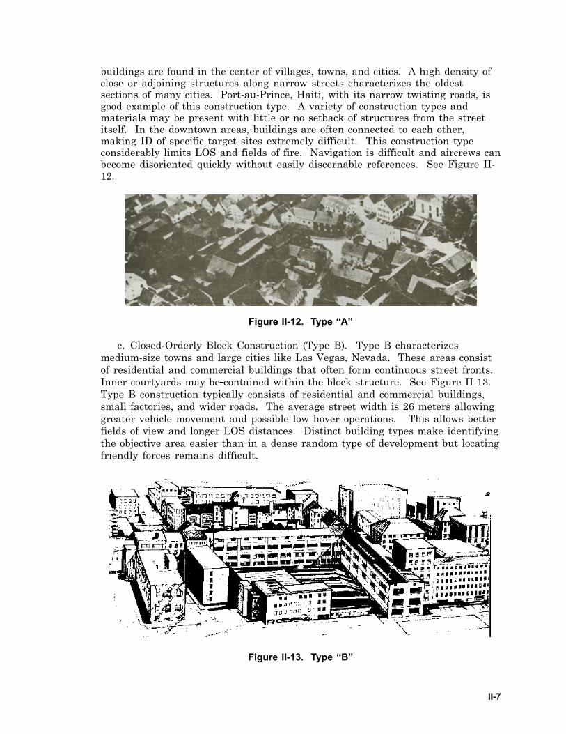
b. Dense, Random Construction (Type A). This type of construction is foundin lesser-developed and nondeveloping nations. Close groupings of older
II-7
buildings are found in the center of villages, towns, and cities. A high density ofclose or adjoining structures along narrow streets characterizes the oldestsections of many cities. Port-au-Prince, Haiti, with its narrow twisting roads, isgood example of this construction type. A variety of construction types andmaterials may be present with little or no setback of structures from the streetitself. In the downtown areas, buildings are often connected to each other,making ID of specific target sites extremely difficult. This construction typeconsiderably limits LOS and fields of fire. Navigation is difficult and aircrews canbecome disoriented quickly without easily discernable references. See Figure II-12.
Figure II-12. Type “A”
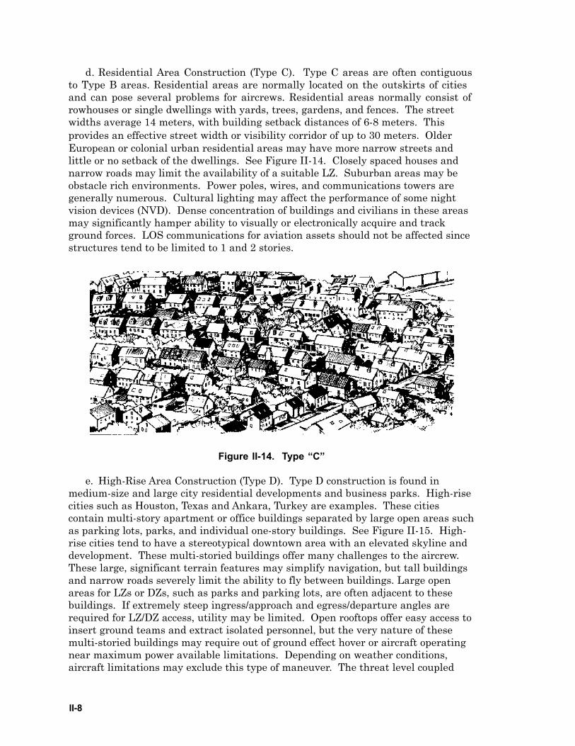
c. Closed-Orderly Block Construction (Type B). Type B characterizesmedium-size towns and large cities like Las Vegas, Nevada. These areas consistof residential and commercial buildings that often form continuous street fronts.Inner courtyards may be contained within the block structure. See Figure II-13.Type B construction typically consists of residential and commercial buildings,small factories, and wider roads. The average street width is 26 meters allowinggreater vehicle movement and possible low hover operations. This allows betterfields of view and longer LOS distances. Distinct building types make identifyingthe objective area easier than in a dense random type of development but locatingfriendly forces remains difficult.
Figure II-13. Type “B”
II-8
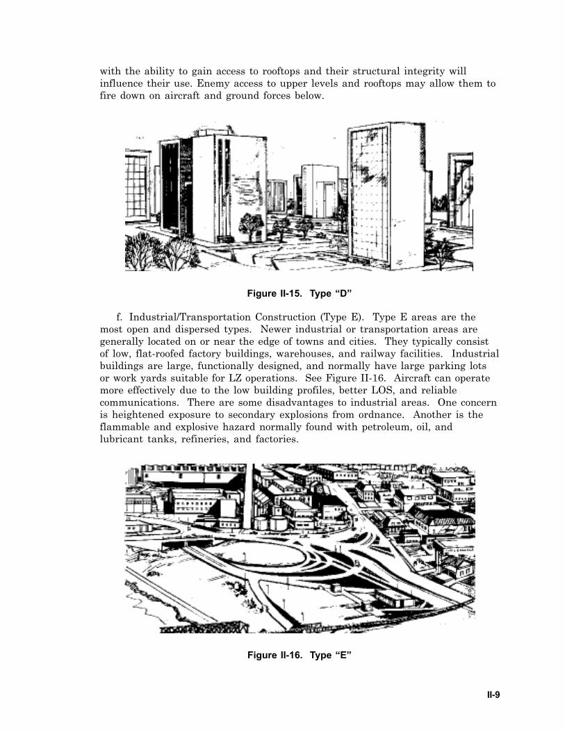
d. Residential Area Construction (Type C). Type C areas are often contiguousto Type B areas. Residential areas are normally located on the outskirts of citiesand can pose several problems for aircrews. Residential areas normally consist ofrowhouses or single dwellings with yards, trees, gardens, and fences. The streetwidths average 14 meters, with building setback distances of 6-8 meters. Thisprovides an effective street width or visibility corridor of up to 30 meters. OlderEuropean or colonial urban residential areas may have more narrow streets andlittle or no setback of the dwellings. See Figure II-14. Closely spaced houses andnarrow roads may limit the availability of a suitable LZ. Suburban areas may beobstacle rich environments. Power poles, wires, and communications towers aregenerally numerous. Cultural lighting may affect the performance of some nightvision devices (NVD). Dense concentration of buildings and civilians in these areasmay significantly hamper ability to visually or electronically acquire and trackground forces. LOS communications for aviation assets should not be affected sincestructures tend to be limited to 1 and 2 stories.
Figure II-14. Type “C”
e. High-Rise Area Construction (Type D). Type D construction is found inmedium-size and large city residential developments and business parks. High-risecities such as Houston, Texas and Ankara, Turkey are examples. These citiescontain multi-story apartment or office buildings separated by large open areas suchas parking lots, parks, and individual one-story buildings. See Figure II-15. High-rise cities tend to have a stereotypical downtown area with an elevated skyline anddevelopment. These multi-storied buildings offer many challenges to the aircrew.These large, significant terrain features may simplify navigation, but tall buildingsand narrow roads severely limit the ability to fly between buildings. Large openareas for LZs or DZs, such as parks and parking lots, are often adjacent to thesebuildings. If extremely steep ingress/approach and egress/departure angles arerequired for LZ/DZ access, utility may be limited. Open rooftops offer easy access toinsert ground teams and extract isolated personnel, but the very nature of thesemulti-storied buildings may require out of ground effect hover or aircraft operatingnear maximum power available limitations. Depending on weather conditions,aircraft limitations may exclude this type of maneuver. The threat level coupled
II-9
with the ability to gain access to rooftops and their structural integrity willinfluence their use. Enemy access to upper levels and rooftops may allow them tofire down on aircraft and ground forces below.
Figure II-15. Type “D”
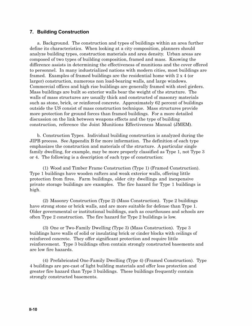
f. Industrial/Transportation Construction (Type E). Type E areas are themost open and dispersed types. Newer industrial or transportation areas aregenerally located on or near the edge of towns and cities. They typically consistof low, flat-roofed factory buildings, warehouses, and railway facilities. Industrialbuildings are large, functionally designed, and normally have large parking lotsor work yards suitable for LZ operations. See Figure II-16. Aircraft can operatemore effectively due to the low building profiles, better LOS, and reliablecommunications. There are some disadvantages to industrial areas. One concernis heightened exposure to secondary explosions from ordnance. Another is theflammable and explosive hazard normally found with petroleum, oil, andlubricant tanks, refineries, and factories.
Figure II-16. Type “E”
II-10
7. Building Construction
a. Background. The construction and types of buildings within an area furtherdefine its characteristics. When looking at a city composition, planners shouldanalyze building types, construction materials and area density. Urban areas arecomposed of two types of building composition, framed and mass. Knowing thedifference assists in determining the effectiveness of munitions and the cover offeredto personnel. In many industrialized nations with modern cities, most buildings areframed. Examples of framed buildings are the residential home with 2 x 4 (orlarger) construction, numerous non load-bearing walls, and large windows.Commercial offices and high rise buildings are generally framed with steel girders.Mass buildings are built so exterior walls bear the weight of the structure. Thewalls of mass structures are usually thick and constructed of masonry materialssuch as stone, brick, or reinforced concrete. Approximately 62 percent of buildingsoutside the US consist of mass construction technique. Mass structures providemore protection for ground forces than framed buildings. For a more detaileddiscussion on the link between weapons effects and the type of buildingconstruction, reference the Joint Munitions Effectiveness Manual (JMEM).
b. Construction Types. Individual building construction is analyzed during theJIPB process. See Appendix B for more information. The definition of each typeemphasizes the construction and materials of the structure. A particular singlefamily dwelling, for example, may be more properly classified as Type 1, not Type 3or 4. The following is a description of each type of construction:
(1) Wood and Timber Frame Construction (Type 1) (Framed Construction).Type 1 buildings have wooden rafters and weak exterior walls, offering littleprotection from fires. Farm buildings, older city dwellings and inexpensiveprivate storage buildings are examples. The fire hazard for Type 1 buildings ishigh.
(2) Masonry Construction (Type 2) (Mass Construction). Type 2 buildingshave strong stone or brick walls, and are more suitable for defense than Type 1.Older governmental or institutional buildings, such as courthouses and schools areoften Type 2 construction. The fire hazard for Type 2 buildings is low.
(3) One or Two-Family Dwelling (Type 3) (Mass Construction). Type 3buildings have walls of solid or insulating brick or cinder blocks with ceilings ofreinforced concrete. They offer significant protection and require littlereinforcement. Type 3 buildings often contain strongly constructed basements andare low fire hazards.
(4) Prefabricated One-Family Dwelling (Type 4) (Framed Construction). Type4 buildings are pre-cast of light building materials and offer less protection andgreater fire hazard than Type 3 buildings. These buildings frequently containstrongly constructed basements.
II-11
(5) Low-Rise Office Building (Type 5) (Framed Construction). Type 5buildings have multi-story steel frame and reinforced concrete construction.They are frequently characterized by large expanses of glass, offering littleprotection from direct fire.
(6) High-rise office building (Type 6) (Framed Construction). Type 6buildings are similar in construction and characteristics to Type 5 officebuildings, but consist of six or more stories.
(7) Low-Rise Apartment Building (Type 7) (Framed Construction). Type 6buildings are similar in size to Type 5 office buildings, but with less glass andwith load-bearing reinforced concrete walls. They offer greater protection fromdirect fire.
(8) High-rise apartment building (Type 8) (Framed Construction). Type 8buildings are similar in construction and characteristics to Type 7 apartmentbuildings, but consist of six or more stories.
(9) Industrial/Warehouse Complexes (Type 9) (Framed Construction). Type9 building construction varies considerably, but is generally steel frame withlightweight exterior walls. Reinforced concrete floors and ceilings are found inmultistory Type 9 buildings.
8. Features of Special Consideration
a. Coastal Features and Waterways.
(1) Background. All hydrography associated with urban terrain warrantscareful analysis. Water features represent possible mobility obstacles to surfaceforces, and are a potential LOC. The presence of a coastline or major waterway isoften the reason that a population center came into existence in a particularplace.
(2) Port Facilities. Port facilities represent a focal point for commerce andlogistics. They hold strategic significance in many cases. Control of docks andassociated facilities accommodates large-scale transport functions into or out of acity. Port seizures may be a primary objective for attacking forces.
(3) Rivers and Canals. Rivers and canals can divide urban areas andrepresent significant physical obstacles to surface maneuver. Control of bridgesand crossing sites is critical to ground mobility and security of an urban area.Major rivers are primary LOCs at a national level. Rivers can be used totransport commodities, raw materials, and finished products. Similarly, militarylogistics requirements can be supported by the use of rivers and canals. Aircrewsshould minimize exposure time over major LOCs.
II-12
b. Airfields. Airfields and other landing sites are major urban commerce andlogistic centers. The flow of commercial and/or military traffic is vital to anoperation. The control of these areas and the airspace around them could be adecisive factor in an operation. Airfields and improved landing areas such aswide, multi-lane, straight highways can accommodate large-scale transportaircraft. Size, load bearing capability, and aircraft parking areas figure greatlyinto the value of an airfield. Seizure of an airfield is often a primary objective.
c. Subterranean Features.
(1) Background. Larger cities feature a variety of subterranean systems ofmilitary significance. A complex network of tunnels and passageways may existbelow the surface. While not visible or directly influencing aviation operations,subterranean features figure prominently into urban operations.
(2) Public Transport. Underground public transport systems, such assubways, represent major LOCs within the urban environment. Tunnelsassociated with these systems can accommodate vehicular traffic and largenumbers of troops.
(3) Passageways. Some cities contain sophisticated undergroundpedestrian passageways and shopping “malls” in the central business district.While generally not large enough to support vehicular traffic, these complexescan be exploited for troop mobility and assembly, logistical operations, and C2.Smaller utility passageways may be quite extensive and optimal for use asinfiltration routes by small forces.
(4) Waterways and Tunnels. Special operations forces (SOF), sappers,terrorists, or partisans may use underground waterways or communicationstunnels. Storm sewers are generally large enough to allow troop movement. Thepassageways, accessed generally through manholes, may be almost as extensive asthe street pattern. Sanitary sewers are usually much smaller, less accessible, andless suitable for use by troops than are storm sewers.
d. Cultural Sites. Cultural and historical sites such as churches, museums,and mausoleums, also are found routinely in urban areas. International lawprovides special protections for many of these landmarks. These areas may bedesignated in appropriate plans such as the airspace control plan. The areas maybe designated as a no fly area (NFA), restricted fire area, restricted operatingzone (ROZ), etc. Fire control measures for other areas such as medical treatmentfacilities, water purification plants, nongovernmental organization (NGO)operating locations, or other structures or areas may be designated.
III-1
Chapter III
FLIGHT OPERATIONS
1. Background
This chapter details the unique considerations of aviation urban operations.Urban operations may include combat, peacekeeping, peacemaking, andhumanitarian support in non-combat environments, as well as combinations of alltypes. Regardless of the type of operation, detailed planning and a thorough JIPBare required. See Appendix B.
2. Threat Considerations
a. Threat Analysis. Intelligence on the threat will be difficult to obtain and moredifficult to accurately update. Areas of control can change rapidly and may beconfusing. Planners must anticipate rapid changes in the threat and incompleteinformation. Every building and structure in an urban area is a potential enemyposition. The presence of snipers, vulnerability to ambush, and difficulty indistinguishing combatants from non-combatants places participants underadditional psychological stress.
b. Reconnaissance. Commanders must establish reconnaissance operationsearly, using all available assets. Unmanned aerial vehicles (UAV) with data linkedvideo are useful assets. Manned aircraft with multiple reconnaissance systems suchas LLLTV, forward-looking infrared (FLIR), and NVDs can provide focusedconcentration of specific areas. These visual systems, coupled with space-basedintelligence, surveillance, and reconnaissance systems (ISR) assets, electronicintelligence systems, voice interceptions, direction finding (DF) platforms networkedwith ground-based systems, CA, SOF, and ground forces provide a picture of theurban environment. HUMINT can provide information on threat intent and forces,as well as information about city infrastructure and status. Gathering detailedinformation during the planning phase of an aviation operation provides plannersand aircrew with information about threat positions, movements, routes, andweapons.
c. Civilian Population. A defending enemy force normally has the advantage offamiliarity with the terrain. The civilian population of the area can play an activerole in the defense. Regardless of its activity, the larger the civilian populationremaining within the area, the more influences it has on military operations.Enemy or friendly forces can have the support of the remaining people. Theirsupport provides significant intelligence, logistics, and security, as well as apotential paramilitary capability.
d. Ground Threat. Urban operations often magnify the threat to aircraft. Lightto medium antiaircraft artillery (AAA) may be employed from ground sites, the topsof buildings, in or near otherwise protected (attack prohibited by ROE, operationalplanning, etc.,) structures, or mounted on civilian vehicles, thus providing aircrewswith a very complex threat picture. A man-portable air defense system

III-2
(MANPADS), with its small size, light weight, rapid engagement capability, andease of concealment, is an excellent weapon for operating in close proximity to or ontop of buildings and other structures. Heavy AAA and surface-to-air missiles (SAM)require open terrain due to radar or siting requirements. However, this does notprevent their employment within urban boundaries. The obstructions and crowdedairspace of cities limit aircraft defensive maneuvering options, increasing theeffectiveness of AAA, MANPADS, and SAMs while at the same time providingexcellent opportunities for the establishment of ambush sites. Urban terrainprovides virtually unlimited concealment, thus complicating escort missions,suppression of enemy air defenses (SEAD), and counter attack. Restricted orbits,weapons employment, and rotary-wing landing approaches increase aircraftvulnerability and limit defensive options. The terrain may also limit suppressionoptions. The cluttered environment (e.g., lights, fires, smoke, dust, etc.) makesidentification of missile launches or ground fire more difficult. Aircrews andplanners should also consider the effects of fixation and visual confusion. Missionsrequiring landing operations must also consider ground threats such as artillery,mortars, or snipers. Planners must expand their view of what constitutes a threatto aviation operations in the urban environment.
3. Weather
a. Background. The aviation commander must establish minimum weatherrequirements before conducting operations. Weather conditions affect the employmentof all aircraft and weapons systems. Adverse weather will hinder the employment ofUAVs, radar, FLIR, laser, optical systems, NVDs, and IR weapons.
b. Ceilings. Low ceilings affect all aviation assets, especially fixed-wing aircraft.Low ceilings can obscure high rise rooftops, and other obstructions such as powerlines, towers, and smokestacks. Low ceilings can also deny fixed-wing aircraft therequired time and altitude to obtain a satisfactory ordnance delivery solution. Thepresence of high rise buildings and low ceilings decreases the effective above groundlevel (AGL) operating area. Low ceilings will also affect the performance of laser-guided weapons. In addition, artificial lighting against a low overcast will highlightaircraft flying under the overcast to ground observers.
c. Visibility. Smog buildup from industrial areas and vehicle exhausts alsoreduce visibility. Smoke from fires and dust from damage and destruction mayreduce the visibility in otherwise clear conditions. Reduction in visibility cansignificantly degrade the performance of weapons sensors and laser or opticallyguided munitions.
d. Winds. In urban areas, the city structure affects wind patterns. Windpatterns are “broken up” and funneled down streets and alleys. While the wind maybe calm along one end of a block, it can be turbulent at another. City structure alsoinfluences the location of turbulent areas. Therefore, predicting turbulent areas isdifficult. Turbulence affects aircraft performance and weapons delivery.
e. Temperatures. IR signatures are affected by the proximity of other buildingsand structures (for example, shadowing and winds). Times of thermal crossover
III-3
occur when objects viewed through IR sensors may be indistinguishable due to theirtemperature similarities with their backgrounds. Thermal crossover in urban areasmay be relatively insignificant due to shadowing effects of structures and the typesof materials (e.g., asphalt, concrete, etc.) making up the background. However,when using a FLIR, aircrews must pay particular attention during this period.Furthermore, during this period, thermal crossover is particularly sensitive to wind,which can affect differences in target and background temperatures. Urbantemperatures are generally higher than those in rural areas and can be 10 to 20degrees higher than the surrounding environment. High thermal contrast canadversely affect thermal sight performance.
4. Command, Control, and Communications
a. Commander’s Intent. A clear understanding of the commander’s intent is animperative for all operations, facilitating initiative in harmony with thecommander’s desires. Through a mission type or operation order (OPORD), thecommander states his intent, allowing subordinates the initiative to achieveobjectives in whatever method the subordinate deems appropriate. In the complexurban environment, maintaining communications can be difficult because ofinterference caused by structures restricting LOS systems. This increases relianceon decentralized execution. Detailed mission orders and briefings aid in conductingoperations.
b. C3 Planning. A detailed, flexible, and redundant C3 plan is essential. Aerialor rooftop retransmission systems and the use of remote antennas may overcomesome of these problems. Airborne C3 support systems (e.g., airborne battlefieldcommand and control center (ABCCC), Airborne Warning and Control System(AWACS), joint surveillance target, attack, radar system (JSTARS), and jointairborne communications center/command post (JACC/CP) equipped C-130/C141s)may alleviate some of these difficulties. Another option is an appropriatelyequipped UH-60 or UH-1 helicopter. Each of these platforms has inherentcapabilities and weaknesses that may make them more or less desirable foroperations in urban environments. Reference system publications and jointplanning publications for more detailed information on capabilities.
c. Air Asset Control. Although all air assets should remain under positivecontrol to the greatest extent possible, procedural control measures may be requiredfor air operations in the objective area. This is especially true in situations whereairborne C3 assets are unavailable or unable to communicate due to interference.Visual signaling may also be affected by vertical development in urban areas.Normal urban clutter makes it harder to differentiate these signals from theirbackground.
d. Common Frequency. A common frequency for all units facilitates rapidtransfer and understanding of information. Specific information concerning multi-Service tactics, techniques, and procedures (MTTP) for air-to-air, air-to- surface, andsurface-to-air brevity codes is found in Service manuals, Field Manual (FM) 90-38,Marine Corps Reference Publication (MCRP) 3-25B, Naval Warfare Publication(NWP) 6-02.1, and Air Force Tactics, Techniques, and Procedures (Interservice)
III-4
(AFTTP(I)) 3-2.5. The issue of common frequency use, particularly for encryptedtransmission, can be greatly complicated in multinational operations. Plannersshould consider this issue and develop methods for in-the-clear communications ifnecessary.
5. Airspace Control
a. Compressed Airspace. Compressed airspace and a unique three-dimensionalenvironment characterize aviation urban operations. These factors increaseplanning and execution problems, especially when in close proximity to friendlyforces and non-combatants. The compressed urban airspace brings separate anddiverse missions into close proximity. For example, an airdrop of supplies could beperformed simultaneously with CAS missions protecting the unit being supplied.Knowledge of other missions tasked for the same area is vital to avoid interference.
b. Control Measures. Develop positive and procedural control measures forspecific airspace. This will assist in eliminating mission conflicts. These measuresmust also consider ongoing host nation (HN) or foreign military airspacerequirements. A useful method of implementing positive control is execution of ajoint air tasking order (ATO) through the Theater Air Ground System (TAGS). Thejoint ATO assures deconfliction and synchronization of aviation assets.Multinational air assets may also be included in the joint ATO. A combination ofpositive and procedural control measures may be appropriate because of thepotential for high volumes of air traffic over urban areas. For example, establishinga ROZ or high-density airspace control zone (HIDACZ) over the area of operations isone means to facilitate the simultaneous employment of aerial platforms.Heightened awareness of support missions operating in and throughout the generalarea must be maintained. Detailed information concerning multi-Serviceprocedures for integrated combat airspace command and control (ICAC2) is providedin Service manuals, FM 100-103-1, MCRP 5-61, NWP 3-52.1, and AFTTP(I) 3-2.16.
6. Air-to-Ground Coordination
Air-to-ground coordination is improved using overlays and pictures. FigureIII-1 depicts an example of a ground unit’s control measures. The sketch numbersmajor structures and labels building corners (A-D) providing a legend to identifyeach building. Establishing objectives and phase lines assists in understanding theground scheme of maneuver and is one method to integrate both air and groundoperations. Specific information concerning multi-Service procedures for a TAGS isprovided in Service manuals, FM 100-103-2, MCWP 3-25.2, NWP 3-56.2, andAFTTP(I) 3-2.17.
7. Maps and Charts—Selection and Preparation
a. General Considerations. Consider all types of geospatial products rangingfrom paper maps and charts to digital mapping databases including commercial aswell as government products. Maps with a larger scale than 1:50,000 (i.e., 1:24,000or 1:12,500) provide greater detail for urban mission planning and execution.Numerous large-scale maps exist to assist aircrews.
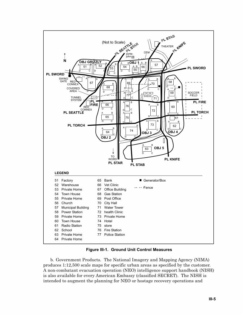
III-5
Figure III-1. Ground Unit Control Measures
b. Government Products. The National Imagery and Mapping Agency (NIMA)produces 1:12,500 scale maps for specific urban areas as specified by the customer.A non-combatant evacuation operation (NEO) intelligence support handbook (NISH)is also available for every American Embassy (classified SECRET). The NISH isintended to augment the planning for NEO or hostage recovery operations and
51 Factory52 Warehouse53 Private Home54 Town House55 Private Home56 Church57 Municipal Building58 Power Station59 Private Home60 Town House61 Radio Station62 School63 Private Home64 Private Home
65 Bank66 Vet Clinic67 Office Building68 Gas Station69 Post Office70 City Hall71 Water Tower72 health Clinic73 Private Home74 Hotel75 store76 Fire Station77 Police Station
LEGEND
Generator/Box
Fence
51 5253 54
5556 57
6768
69 70
71
58
59
60
61
62
72
73
74
75
76
77
63
64
65
66
porta-john
CEM
THEATER
SWINGGATE RED
CONNEX
REDCONNEX
COVEREDAREA
TUNNELSYSTEM
SOCCERFIELD
A B
D C
A B
D CD C
BA A B
D CD C
A BA B
D C D C
A B
A B
A B
D C D CD C
A B
AB
D C
A B
D CA B
D C
AB
D C
A B
D C
A B
D C
A B
D C
A B
D C
A B
D C
A B
D C
A B
D C
A B
D CA B
D C
A B
D C
A B
D C
SHEDS
OBJ 3
OBJ 5
OBJ 2
OBJ GRIZZLY OBJ 1
OBJ 4
PL SWORD
PL TORCH
PL STAR
PL FIRE
PL KNIFEPL STAB
PLFIRE
PL SEATTLE
PL TORCH
PL SWORD
TOWORD
N
(Not to Scale)
III-6
contains information such as pre-surveyed LZ listings. Planners must considercurrency of terrain information during planning.
c. Civilian Maps. Commercially available civilian or tourist maps may showgreater and more current urban detail than military maps. While street maps andtourist maps do not normally show terrain, they often provide useful information oncurrent street and bridge locations, street names, shapes of prominent buildings,and cultural features. Civilian maps usually have a reference grid overlay that, ifavailable in sufficient quantities, may be useful as a supplemental terrain referenceduring urban operations. However, these maps do not come marked with theMilitary Grid Reference System (MGRS) or universal transverse mercator (UTM)references. Although marked with a common reference grid, commercial maps orcharts should not be used as a reference for employing munitions. Ensure all unitsdisseminate any approved non-standard reference systems to enable proper targetID and fratricide prevention.
d. Geospatial Products. Units must maintain accurate geospatial products fortheir operational area and continuously update them as new features and hazardsare identified. This is a shared responsibility for aircrews, intelligence personnel,and operations sections. For example, the intelligence staff, as part of the JIPBprocess, should conduct initial preparation of the maps and charts since intelligencesources may be the only source of hazard information before mission execution.Other sources of hazards include the airspace authority that publishes known flighthazards, such as the notice to airmen. Detailed analysis of flight hazards duringmission planning is critical to safe flight operations in urban terrain. Many hazardsmay be unlit and difficult to discern amongst the bright ground lights. Severaltypes of flight hazards exist:
(1) Physical Hazards. The majority of physical hazards within an urban areaare manmade. These include antennas, wires, power lines, Tube-launched, opticallytracked, wire-guided (TOW) missile wires, and other obstructions.
(2) Environmental Hazards. Environmental hazards include meteorologicaleffects, extremes in artificial illumination, and unpredictable wind effects.
(3) Natural Hazards. Natural hazards include tall trees, and areas of highbird concentration.
(4) Air Traffic Hazards. The high volume of air traffic over and within urbanareas is another significant hazard.
(5) Other Hazards. Other hazards include high intensity radio transmissionareas. All known radio emitters should be assessed for potentially adverse effectson aircraft systems.
WARNING: Check the reference system used to prepare a map or chart (i.e.,World Geodetic System 1984 (WGS-84), Tokyo Special, etc.). Different datumcan cause significant confusion and errors.
III-7
8. Route Planning and Navigation
a. Planning Factors. Appropriate flight profile and route selection are perhapsthe most difficult planning factors. A dynamic flight profile offers the bestsurvivability and responsiveness. Aircrews should base their flight profile ontraditional factors of mission, enemy, terrain and weather, troops and supportavailable, and time available. Special consideration must be given to the uniquecharacteristics of urban terrain. Plan appropriate routes and altitudes to considerknown threats and exploit environmental factors such as wind direction, moon angleand azimuth, and urban noise.
b. Navigation Techniques. In an urban environment, a small navigational error(i.e., a couple of city blocks) can rapidly evolve into disorientation. Although naturalland features (rivers, lakes, etc.) are preferable landmarks, they may not be useableduring various flight profiles. Manmade features may provide the majority ofavailable navigation aids. If possible, pick large recognizable features fornavigation. Examples include cemeteries, stadiums, cathedrals, and major roads.Linear features, such as major highways, rivers, railways, canals, and coastlinesprovide easily recognizable boundaries and references to assist aircrews inmaintaining orientation. Prominent rail and highway interchanges are useful as enroute checkpoints. However, remember that in enemy-held areas, these sameprominent features might be protected by anti-air weapon systems. As aircrewsbecome more familiar with the operational area, more use is made of locallandmarks during flight.
c. Enhancing Survivability. Low-level flight techniques, adapted for urbanterrain, may be employed to enhance survivability. Remaining unseen visually andelectronically is the most effective method of preventing an engagement by hostileforces. Obviously, if there is no tactical reason to operate in low profiles (i.e.,disaster assistance operations), higher profiles are more suitable and safer. “High”versus “low” is matter of carefully weighing the factors, making an informeddecision, and remaining flexible if the situation dictates a profile change. Thenavigation techniques employed and the use of night systems will factor greatly intothe degree of risk and effectiveness of a particular profile. Distilled to its most basicelements, the issue is this: “do aircrews want brief exposure to hostile weapons atclose range, or continuous enemy observation and exposure to weapons at extendedslant range?”
d. Route Planning. A network route structure of air control points (ACP) androutes (preferably surveyed) may be used to facilitate route planning, navigationand C3. See Figure III-2. ACPs are especially useful for aircraft navigation systemsthat require visual updates. Different sequences of ACPs appropriate to the missionmay be assigned code words to facilitate operational security, control, and routechanges in flight. For example, “Broadway” may be a route with ACP sequence 2, 7,and 8; “Wall Street,” ACPs 1, 6, and 3; “Bourbon”, ACPs 4, and 9; etc. Before everbeing used in a tactical environment, a clearly defined initial point (IP) should beverified by aircrews of high performance aircraft to ensure that both IP data andaircraft systems are correct and reliable. Offset aimpoints may also facilitate targetID. The location of these points should be published in all applicable plans and

III-8
Figure III-2. Network Route Structure
orders. In situations where enemy forces are present, great care must be taken toavoid predictability of routes. Whenever possible, plan to use routes, battlepositions, attack by fire positions, airspace coordination areas (ACA), holding areas,and orbits over friendly held terrain that do not expose aircraft to threats. Terrainand congested airspace may force repeated use of ACPs, LZs and flight profiles. Thehabitual flying of routes from one obvious feature to the next, or along LOCs, isstrongly discouraged in the presence of enemy forces or potentially hostile civilians.Avoid predictability of flight routing in all but the most benign of operationalenvironments. Track the frequency that each ACP is used to better control routeover-use. Route names and “call signs” should not be re-used repetitively with thesame ACP sequence. Flight profiles must take into consideration small arms, AAA,MANPAD, and SAM weapon ranges and communications.
W A L L S T R E E T
O B J
2
78
6
4
3
91
III-9
e. Effective Navigation. Navigation over urban terrain can be more difficultthan over natural terrain due to an over-abundance of cues. Navigation is also moredifficult for rotary-wing aircraft because most maps do not show the verticaldevelopment of urban terrain. The high density of structures, variety ofgeographical references, and high light levels can create “visual saturation.” Rapiddisplacement from position to position can sometimes create confusion betweenaerial and ground observers as to cardinal directions or locations. Familiarity withthe characteristics of urban terrain allows aircrews to discern key features in thisenvironment. Navigational aids, such as the global positioning system (GPS), havereduced but not eliminated this problem. Effective navigation over large towns andcities can require the use of a variety of navigational systems and techniques. Theuse of GPS eases the problems associated with night navigation and orientation;whereas, handheld laser pointers or designators ease the problems associated withorientation and target ID. Aircrews must monitor their equipment closely andcrosscheck their position by all available means. Navigation systems may bedegraded due to interference induced by buildings. Aircrews should performdetailed mission planning to maximize the effectiveness of all available assets.
9. Night Vision Devices
a. Considerations. When planning for and employing NVDs, aircrews must paycareful attention to the color, location, and intensity of urban lights, in addition tothe moon angle and lunar illumination along the flight route and in the objectivearea. Night imagery of the area is an important tool for effective analysis andmission planning. To determine when and where to use NVD, image intensifiers, orIR sensors, a detailed analysis of the area is necessary. Aircrews should prepare tomake frequent and rapid transitions from aided to unaided flight during urbanflights.
b. Characteristics. Night vision goggles (NVG), and FLIR/Integrated DisplaySystem (IDS) are affected by the composition and surface conditions of urbanterrain. A rural battlefield has a somewhat homogeneous composition where man-made objects contrast sharply. However, in an environment that consists primarilyof manmade objects there is very little consistency in the thermal/visual scene.High light levels in urban areas create special problems. The volume and irregularpatterns of ground lights in urban areas affect NVG operations. The FLIR/IDS is anexcellent identification aid for terrain features and hazards in brightly-lighted nighturban environments as it is not susceptible to blooming effects from overt lightingas are NVG. Brightly lit cities can be navigated without NVDs, but discerningdetail in darkened areas or shadows requires using image intensifiers or IR sensors.Relatively dark areas, such as large city parks, are readily identified and make goodnavigation references at night. Cultural lighting will often washout NVG,decreasing their effectiveness.
c. Environmental Concerns.
(1) Lighting Condition. Operations conducted during twilight, dawn, or duskmay present problems. The rapid changes in the illumination during these periodsand the inability of the eyes to quickly adjust make it difficult for aircrews to
III-10
observe terrain features and see other aircraft. FLIR devices are not affected byartificial light and are generally effective navigation and targeting systems duringthis period. However, they are subject to being overpowered by intense heat sourceswithin their field of view. Very hot areas, such as factory smoke stacks or fires,make the details of objects with lower thermal contrast difficult to discern. Hostileforces may attempt to degrade the effectiveness of thermal systems by lightingbonfires, buildings, cars, tires, etc. in the area of operations. If a supported groundunit is using laser pointers, aircrews using FLIR will not be able to detect the spot.The laser pointer is detectable with NVG.
(2) Thermal Clutter. FLIR/IDS thermal clutter occurs when there are anumber of objects in the sensor’s field of view with approximately the same thermalsignature. These objects can be “cool”, leading to an overall dark image, or “hot”enough to result in an image saturated with bright spots. Overlapping hot spotsresults in overall reduced image quality. Using the gain and/or polarity functionscan enhance FLIR/IDS imagery enough to highlight cultural features. Smoke froma smoke grenade and/or burning diesel fuel will not affect the FLIR/IDSsperformance. A good rule of thumb is that if you can detect a target with a FLIR/IDS and consistently employ the laser ranging and designation functions, then youcan most likely designate and lase the target satisfactorily for a laser-guidedweapon. Generally all buildings will be seen and recognizable on the FLIR/IDS.Building roofs will present a different signature from walls due to the materialemissivity, and this may act as another cue aiding target acquisition. If aircraft areforced to operate below 200’ AGL, then the low slant angle will make buildingacquisition difficult and personnel/vehicle target acquisition more difficult. Slightvariations in construction material for either roads or structures can alter the imageenough to inhibit target acquisition and tracking. For example, while the terminalguidance controller may see an NVG image of two contrasting materials around atarget, the aircrews using a FLIR/IDS may not see the same contrast due to thedifferences in temperature and emissivity. Furthermore, airspeed and altitude canhave the same affect.
(3) Thermal Reflection. Thermal reflections can produce odd signatures,making target ID difficult. Smooth or glassy surfaces such as windshields,unpainted metal surfaces, or water are examples of thermal reflectors. They canreflect IR radiation images, like a mirror, of other nearby sources. They can appearvery dark because they reflect the low radiant temperatures from the night sky.Most buildings constructed from concrete or brick will have high thermal mass,meaning their rate of temperature gain will be slow during the day (until noontime)and rate of loss will be slow during the night. Urban structures viewed mid-day canbe distinctly different from a late afternoon view after having been heatedthroughout the day; structures of plywood or aluminum lose heat quickly andprovide high thermal contrast with backgrounds that cool more slowly. As lateafternoon approaches, heat dissipates quickly. In the morning, objects facing thesunrise will heat more quickly, appearing hotter than objects that face away fromsunrise. Air conditioning or heating units on buildings can produce localized hotspots. Windows will appear very dark when reflecting the night sky temperature.However in a combat zone, as was seen in Bosnia, many building windows may bebroken out.
III-11
(4) Smoke/Fog. FLIR/IDS visibility through fog or smoke is very good.However, smoke from burning phosphorous or flares significantly hinder thermaltransmission. The atmosphere can attenuate transmission of IR energy throughrefraction, absorption or scattering. High water vapor concentrations, which occurat high humidity, are responsible for the majority of IR absorption. Urban areas canhave significant concentrations of carbon dioxide, which is also an IR absorber, canpotentially degrade FLIR/IDS performance. In practice, carbon dioxide absorptiondoes not usually impact FLIR performance.
10. Rotary-Wing Operations
a. Background. A typical rotary-wing urban flight profile consists of modifiedlow-level and contour techniques. Aircrews must evaluate obstacles, ambient lightlevels, and available navigation cues as well as types and locations of threat sourcesto determine the optimum altitude and airspeed. Maintaining higher airspeeds canminimize exposure time. To limit exposure to antiaircraft weapons, the preferredmethod of ingress and egress is a low, swift flight profile. However, slower flightspeeds may be necessary to allow enough time to precisely identify and navigate tothe objective area. Avoid true nap-of-the-earth flight as it exposes the aircraft to agreater potential for engagements. Slow speeds coupled with low altitudes can putthe aircraft and aircrews at greater ground threat risk (small arms, rocket-propelledgrenades, etc.). A low density of structures or extensive enemy use of high rooftopsdiminishes the masking advantages of low flight profiles. To buffer obstacle andhazard clearance, a higher flight altitude (300 to 500 feet AGL) over a city, day ornight may be necessary. However, flight at higher en route altitudes exposes theaircraft to observation as it approaches the objective and makes it far morevulnerable to engagement during the descent for landing. This exposes aircraft toshoulder-launched or radar-guided SAM threats. However, the trade-off provides abetter margin of safety from the hazards of unlit towers, cranes, and power-linesthat blend into the urban landscape and are more difficult to detect.
b. Flight Profile. Areas of consideration when determining flight profilesinclude:
(1) The mission requirements.
(2) The hazards to flight.
(3) The integrated air defense system (IADS) in use by adversary forces.
(4) The small arms threat.
(5) The terrain relief and building height in and around the area.
(6) The density of structures.
(7) The accessibility/security of high, dominant rooftops.
(8) The dominant natural terrain around the urban area.
III-12
(9) The SAM threat.
c. Multi-ship Operations. Multi-ship rotary-wing operations are challengingand can require application of unique formation techniques, especially whenoperating with NVDs. To prevent the loss of visual contact with other aircraftamong ground lights, a non-traditional vertical “stack-down” formation positioningmay be required. Planning must include formation break-up and rendezvousprocedures if visual contact is lost within the flight or evasive maneuvering isexecuted. When multiple aircraft are operating together, consider greater formationspacing to facilitate more flexible maneuvering while still providing mutual support.A wingman flying in a vertical “stack down” position from the preceding helicopterwill not have the flexibility of maneuver normally enjoyed in the traditional vertical“stack up” position. Maintain a position that compensates for the illuminationpollution, but avoids jeopardizing the aircraft by greater exposure to obstaclehazards or increased formation collision potential.
d. Aircraft Lighting. For both day and night operations, Aircrew shouldexperiment with aircraft external lighting to best accommodate the mission,otherwise follow standing operating procedures (SOP). If overt external lighting ismandated, use the flash position to better distinguish aircraft from static lightsources. In brightly-lighted areas, covert lights may not be visible. Aircrew shouldweigh mission lighting needs against the possibility of visual detection by theenemy. During Operation JUST CAUSE, reflective tape was placed on all friendlyaircraft to assist in identification during ingress and egress. Bright ambientillumination can be favorable at times. During Operation EASTERN EXIT, the1991 NEO operations in Somalia, evacuees commented that in the darkened landingzone, they could hear the helicopters but did not see them until they were already onthe ground.
11. Fixed-Wing Operations
a. AC-130 Gunship Operations. Due to AC-130 characteristics and theirrequirement to fly under the protection of darkness in higher threat environments,special consideration must be given to the threat. Commanders and planners mustconsider the threat determined in the JIPB process before tasking the AC-130because its effectiveness in interdiction or ground support missions could be limitedby a number of factors unique to the urban environment. Using a wide range ofaltitude and orbit patterns, the AC-130 is a versatile platform and can performmissions ranging from C3 to CAS. If employed correctly, the AC-130 can providecommanders with excellent situational awareness. The AC-130H and the AC-130Ucurrently employed generally operate in the same manner but have somedifferences. The AC-130U is all weather capable for interdiction and can predictimpact points of fired ordnance. Reconnaissance in instrument meteorologicalconditions is degraded due to the ability to detect only radar significant targets (i.e.,
WARNING: If stacking down, pay strict attention to disk spacing and have apre-briefed formation break-up plan. Formation break-up from a stack-lowposition is more dangerous than from a stack-high position.
III-13
buildings, LOCs, vehicles, etc.), but not enemy personnel. In visual meteorologicalconditions, both the “H” model and the “U” model are effective. While in theweather, use of radar beacons along with a target reference points (TRP), grid,UTM, or latitude/longitude are highly desirable to identify friendly positions andinitiate calls for fire. During night operations, the AC-130 can provide excellentcovert illumination with its IR spotlight.
b. Fighter/Attack Operations (AV-8, A-10, F-16, F/A-18, etc.). Missions involvingthese aircraft take into consideration en route threat status, weather, and airspacerestrictions in much the same manner as missions in non-urban environments. Iffriendly ground forces or non-combatants are a factor, aircrews will conduct themission as a CAS mission. If friendly ground forces or non-combatants are not afactor, then it may be conducted as a strike mission. For example, this method wasused during operations in Kosovo and Serbia in 1999. Once in the target area,terminal procedures are governed by target area threats, location of friendly forcesor civilians, onboard sensor and weapon availability, and specific target geometry.For example, in a low threat environment status, aircraft can orbit the objectiveoverhead for target acquisition in support of the ground element. As the threat levelincreases, aircrew may elect to offset from the threat while keeping sensors on thetarget area. They may also choose to climb or employ contact point to IP ingresstactics.
c. Airlift Operations. Airlift missions, in general, can be broadly categorized aseither airland or airdrop. By far, the vast majority of airlift missions are airland.Consequently, since most airfields are in or near cities, most airlift missions willinvolve some planning for urban environments. Airdrop missions may be conductedin conjunction with humanitarian and disaster-relief efforts and often will beperformed in or near urban environments. Direct airdrop support of ground forcesoperating in urban areas, while relatively rare, will require precise navigation andconsiderable pre-mission planning/coordination. In the event of humanitarian ordisaster-relief missions, aircrews and planners may be required to coordinate withnumerous NGO relief agencies, many of which are unfamiliar with airlift andmilitary operations. Prior coordination and direct control of these personnel duringdrop and on/off load operations will greatly aid in safe mission performance.
(1) En Route Operations. Basic planning considerations for en route portionsof both airland and airdrop missions in urban areas should be the same as foroperations in other environments. The nature of urban terrain, however, can limitthe flexibility of how these considerations are applied. For instance, formationairdrop operations increase mass on target and shorten the time required to securedrop zones. Urban areas, however, may not allow the use of large formations due toconfined airspace, obstacle altitudes, and the requirement for verbally initiatedrelease system (VIRS) drops. These limitations drive planners to the use of multiplesmall formations or single ship operations. Likewise, the nature of urban threatsand the inability to positively secure airfields 24 hours a day can severely limitroute and altitude selection for airland missions. Humanitarian and disaster-reliefmissions, as well as normal logistics support missions, can involve considerablethreat to aircrews due to political sensitivities and the possibility of terroristactivities. The capability to use aircraft defensive systems over or near urban areas
III-14
for either airland or airdrop missions, particularly if those missions are considered“non-combat” in nature, may need to be coordinated in advance.
(2) Airland. Approach and departure operations at urban airfields wherethreats have been identified or are suspected cause planners significant problems.Aircraft are most vulnerable during approach and departure due to their slow speed,configuration, predictability, and lack of maneuverability. Close proximity ofbuildings and LOCs to flight paths will require either the use of security measures(e.g., helicopter or foot patrols of the area at random intervals) or specific aircrafttactics (e.g., random steep or shallow approaches/departures) to lessen thepossibility of attack. These efforts will be less effective if structural densityincreases near the airfield. Tactical approach selection must be based on threat,terrain, obstacles, and the proximity of the airfield to significant urban features notunder the control of security forces. The use of overt aircraft external lightingshould be carefully considered when MANPADS threats are a possibility.Coordination with air traffic control (ATC) and airfield defense forces is mandatoryto ensure safety and prevent fratricide. This may involve considerable coordinationwith HN personnel. Aircrews should be aware that control of civilians on runwayshas been a problem in past humanitarian operations. Vigilance during approachesto minimally controlled airfields in urban areas must be practiced to ensure go-arounds can be performed in the event civilians cross or enter runway areas.
(3) Airdrop. As with all airdrops, primary considerations for urban airdropmissions will revolve around drop and escape procedures, locations and markings ofDZs, run-ins, IP selection, and aircraft/formation tactics. The unique aspects ofurban terrain and their effects on airdrop missions must be considered to ensuresuccess. The large numbers of visual cues found in urban terrain (e.g., buildings,lights, vehicles, etc.) will complicate DZ marking and route visual turn point ID.Positive radio contact with DZ personnel may be more difficult and take longer toestablish due to interference from structures/electronic sources. The possibility ofunapproved personnel on the DZ must be considered and additional no-dropprocedures should be coordinated. Be aware that DZ control personnel may offsetfrom the proposed DZ area to avoid giving away its position and, consequently,enable civilians to “rush” the airdrop loads.
12. Airfields
a. Background. Many airfields are located in or near urban areas. Planning foraviation urban operations should include an assessment of available airfieldfacilities. Urban airfield operations are a challenge for forces tasked with operatingand securing them. The airfield location is known and easily identified. Aircraftmay be vulnerable during approach, landing, hover, and departure operations evento low technology threat systems.
b. Airfield Operations. On the ground, aircraft are susceptible to surface-to-surface threats such as artillery, mines, booby traps, mortars, rockets, missiles, andweapons of mass destruction. Planners should also anticipate and include in theirassessment the presence of major roads and the proximity of urban structures and

III-15
industrial facilities in and around the airfield approach/departure routes. As aminimum, consider the following when planning airfield operations:
(1) Arrival and departure routing and maneuver limitations,
(2) Size of useable runways (length/width/obstructions),
(3) Turnaround areas and the capability for emergency departure,
(4) Taxiways and obstructions to taxi routes,
(5) Aircraft and vehicle parking areas, on/offload sites, access to each,
(6) Ground access routes and securing them,
(7) Security of airfield buildings and the perimeter,
(8) Hazardous terrain, towers, buildings, wires, etc. near flight areas,
(9) Instrument/visual procedures,
(10) Terminal area threats,
(11) Weather,
(12) Base infrastructure and billeting for aerial port of debarkation personnel,
(13) Security of approach and departure corridors,
(14) Fuel and fuel transfer support.
13. Helicopter Landing Zones (HLZ)
a. Background. Studying city composition, imagery, and maps provides a goodfoundation for choosing HLZs. Updated imagery should be reviewed to accuratelyassess HLZ size and hazards. If possible, imagery should be taken at the same timeof day that the HLZs are to be used. This allows analysis of illumination andshadow conditions to be encountered during the actual mission. Ground photos canprovide valuable hazard information and terrain reference. Carefully examine HLZ/PZ reports and diagrams from reconnaissance assets and make these available to allparticipants. Annotate all images and diagrams with magnetic north andnavigation references.
b. Selection. Consider selecting an urban HLZ that is readily identifiable andaccessible. Most major cities have urban parks near the central business districtthat may provide a suitable HLZ. Other potential HLZs include athletic stadiums,parking lots, and rooftops. Alternate HLZs in the objective area and emergencyHLZs en route should be planned to the same degree of detail as primary HLZ.Some structures can accommodate helicopters landing on the rooftop. In cases
III-16
where the load bearing capacity can be readily evaluated, (such as with existingrooftop helipads or with the availability of building design data), rooftops constituteviable HLZs. Some major cities have codes requiring rooftop helipads for buildingstaller than a certain number of stories. These pads may have the maximum weightbearing capacity painted on the pad. The load bearing capacity of a rooftop cannotbe accurately determined by simple observation. Roof clutter, such as antennas,lightning rods, and wires, can obstruct the landing area. Aircrews must also beaware of the unpredictable wind and venturi effects associated with flight in closeproximity to very tall buildings, as well as out-of-ground-effect operatingrequirements. These effects can require additional power during operations to andfrom high rise rooftops.
c. Quality. HLZs, particularly those suitable for large multi-ship formations, areoften limited in urban terrain. A careful balance must be made between the limitedavailability of suitable HLZs and exposure to observation, direct fire, or an ambush.Consider whether the mission is conducted during daylight or darkness. Daylightallows rapid ingress, egress, and facilitates navigation, but also allows for easierobservation and engagement by the enemy. Night or NVG missions offer improvedconcealment and HLZ security, but require slower airspeeds and increase thedifficulty of navigation.
d. Tactical Considerations. The tactical considerations for HLZ/PZ selection,including mission, location, and security, are exacerbated in urban terrain. If thereare more aircraft than a single HLZ can accommodate, select multiple HLZs inproximity to the objective. Control measures must be adequate to deconflict themovement of all elements. Formations of assault helicopters should be no largerthan will be able to land at the HLZ simultaneously. All secondary or alternateHLZs should be at least the same size to prevent unnecessary exposure to aircraftwaiting to land. Give special consideration to the possibility that threats frommultistory buildings can be above the vertical fields of fire of the aircraft gunners.
e. Alternate Insertion/Extraction (AIE). Aircrews can use a variety oftechniques for AIEs onto rooftops. These methods include:
(1) remaining light on the landing gear after touchdown,
(2) hovering with a single skid or landing gear touching the structure,
(3) rappelling,
(4) fast rope,
(5) rope ladders,
(6) hoist operations.
If rooftop insertions are attempted, planners must consider enemy line of sight tothe rooftop and potential exposure of helicopters and troops to enemy fire while incritical flight profiles. If more than one insertion/extraction element is required,
III-17
consider utilizing multiple insertion flight profiles to remain unpredictable and toavoid objective area congestion. In general, fast ropes and hoist cables aremanufactured in fixed lengths. Planners must ensure that AIE equipmentrequirements and availability are determined and that missions are not assignedthat exceed current inventories and configurations.
14. Special Use Areas
a. Drop Zone. The availability of usable DZs may be limited. Parks, roads,railroad yards, airfields, athletic stadiums, and industrial storage sites are the mostlikely locations for airdrops. DZ operations in urban terrain are difficult due tosurface obstructions, navigation, and positive ID of the DZ. Communicationslimitations, positive marking, DZ control, and the availability of accurate, timelyintelligence also affect airdrop accuracy. Lessons learned from recent operationsemphasize the importance of positively controlling personnel near the DZ, orconcealing DZ locations until immediately before airdrops occur. This reduces thepossibility of situations where civilians are injured by the airdrop. One exception tothis is the airdrop of meals ready to eat (MRE), which have been conducted directlyover urban areas using the tri-wall aerial distribution system that free-falls andspreads individual packets over a wide area.
b. Forward Arming and Refueling Point (FARP). Assessment of potential FARPlocations is similar to the basic considerations for LZ/PZ selection. Consider thelocation’s ability to accommodate the refueling/rearming element, the number ofpoints required, whether the landing and holding area is adequately sized for thenumber and type of aircraft to be used, and if there is sufficient movement area.Aircraft in an urban FARP are vulnerable during refuel/rearm operations due to theproximity of concealment for threat forces. FARP locations should provideconcealment from the surrounding terrain, buildings, and facilitate securingpotential ground entry and exit routes. Sports stadiums may be suitable for thispurpose.
c. Contingency Areas. Loitering in-flight over urban terrain is very dangerous,especially during day combat operations. Planning for in-flight contingencies mayrequire use of assembly areas (AA) or holding areas. When necessary, plan to loiteror hold at control points well away from the urban area. The selection of AAs orholding areas requires the same consideration of technical and tactical factors asHLZs and FARPs. Selection of the proposed area(s) requires a security assessment.Concealment, the presence of friendly ground forces for security, and protective orcovered facilities for personnel and equipment also must be considered. Thecommunications plan must ensure an adequate communications capability withelements in the holding area. This can involve the use of an airborne command andcontrol asset or retransmission platform.

IV-1
Chapter IVWEAPONS EMPLOYMENT
1. Introduction
Aviation urban operations require extensive intelligence collection and aflexible and capable targeting capability. Weapons requirements for urbanoperations can be different from those for open terrain operations. Plannersmust consider military necessity, proportionality, collateral damage, non-combatant casualties, and precision engagement weapons. The ordnancerequirements for a specific mission must focus on the target, employmenttechniques, minimum collateral damage, and the capability to safely employ inproximity to friendly ground forces.
2. Weapons Selection
a. Background. The focus of weapons selection is to produce a desiredweapons effect on a target while avoiding fratricide and minimizing collateraldamage. Other factors influencing weapons selection are commander’s intent,LOW/LOAC, ROE, day or night employment, target type, proximity of buildings,and friendly/non-combatant positions. In the urban environment, some type ofprecision munitions is often the first choice. Non-precision munitions may beused depending on the situation.
b. Collateral Damage. Minimizing collateral damage protects non-combatantsand property, facilitates future operations, and reduces the costs of rebuilding.The presence and proximity of friendly ground forces and the effects of rubble canbe essential considerations in weapons selection. To achieve the desired level ofdamage, it is necessary to carefully select the weapons load (Appendix C). Forexample, cluster and general purpose munitions are effective against troops andvehicles in the open. On the other hand, hardened, mobile, or pinpoint targetsmay require precision munitions. In all cases, the requesting commander shouldknow the type of munitions scheduled for delivery, and the residual effects causedby these munitions (e.g., unexploded ordnance).
c. Considerations. Planners and aircrew must consider the following whenchoosing weapons.
(1) Hard, smooth, flat surfaces with 90-degree angles are characteristic ofman-made targets. Due to aviation delivery parameters, munitions will normally
“We cannot destroy or significantly damage the infrastructure of a foreign urbancenter in pursuit of mission attainment and expect the population to remainfriendly to either US forces or those we support. Neither can we indiscriminatelyuse force in imprecise ways that cause unnecessary non-combatant casualties.”
The Defense Science Board Report on MOUT
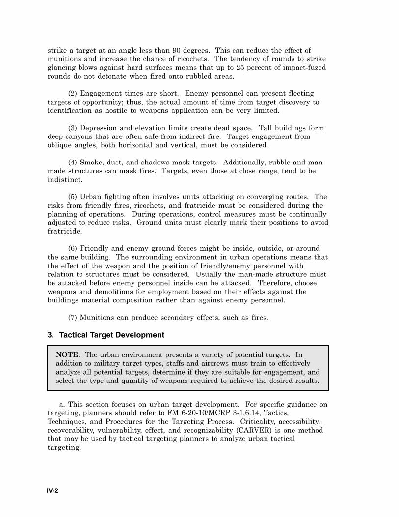
IV-2
strike a target at an angle less than 90 degrees. This can reduce the effect ofmunitions and increase the chance of ricochets. The tendency of rounds to strikeglancing blows against hard surfaces means that up to 25 percent of impact-fuzedrounds do not detonate when fired onto rubbled areas.
(2) Engagement times are short. Enemy personnel can present fleetingtargets of opportunity; thus, the actual amount of time from target discovery toidentification as hostile to weapons application can be very limited.
(3) Depression and elevation limits create dead space. Tall buildings formdeep canyons that are often safe from indirect fire. Target engagement fromoblique angles, both horizontal and vertical, must be considered.
(4) Smoke, dust, and shadows mask targets. Additionally, rubble and man-made structures can mask fires. Targets, even those at close range, tend to beindistinct.
(5) Urban fighting often involves units attacking on converging routes. Therisks from friendly fires, ricochets, and fratricide must be considered during theplanning of operations. During operations, control measures must be continuallyadjusted to reduce risks. Ground units must clearly mark their positions to avoidfratricide.
(6) Friendly and enemy ground forces might be inside, outside, or aroundthe same building. The surrounding environment in urban operations means thatthe effect of the weapon and the position of friendly/enemy personnel withrelation to structures must be considered. Usually the man-made structure mustbe attacked before enemy personnel inside can be attacked. Therefore, chooseweapons and demolitions for employment based on their effects against thebuildings material composition rather than against enemy personnel.
(7) Munitions can produce secondary effects, such as fires.
3. Tactical Target Development
a. This section focuses on urban target development. For specific guidance ontargeting, planners should refer to FM 6-20-10/MCRP 3-1.6.14, Tactics,Techniques, and Procedures for the Targeting Process. Criticality, accessibility,recoverability, vulnerability, effect, and recognizability (CARVER) is one methodthat may be used by tactical targeting planners to analyze urban tacticaltargeting.
NOTE: The urban environment presents a variety of potential targets. Inaddition to military target types, staffs and aircrews must train to effectivelyanalyze all potential targets, determine if they are suitable for engagement, andselect the type and quantity of weapons required to achieve the desired results.
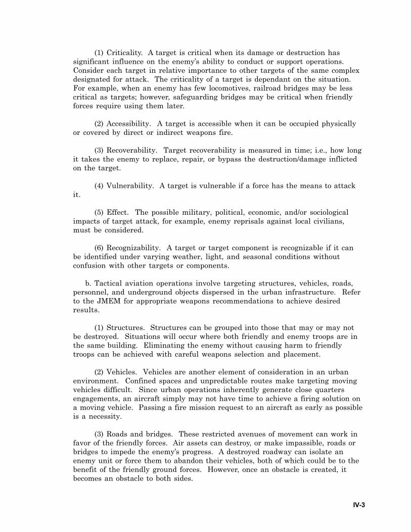
IV-3
(1) Criticality. A target is critical when its damage or destruction hassignificant influence on the enemy’s ability to conduct or support operations.Consider each target in relative importance to other targets of the same complexdesignated for attack. The criticality of a target is dependant on the situation.For example, when an enemy has few locomotives, railroad bridges may be lesscritical as targets; however, safeguarding bridges may be critical when friendlyforces require using them later.
(2) Accessibility. A target is accessible when it can be occupied physicallyor covered by direct or indirect weapons fire.
(3) Recoverability. Target recoverability is measured in time; i.e., how longit takes the enemy to replace, repair, or bypass the destruction/damage inflictedon the target.
(4) Vulnerability. A target is vulnerable if a force has the means to attackit.
(5) Effect. The possible military, political, economic, and/or sociologicalimpacts of target attack, for example, enemy reprisals against local civilians,must be considered.
(6) Recognizability. A target or target component is recognizable if it canbe identified under varying weather, light, and seasonal conditions withoutconfusion with other targets or components.
b. Tactical aviation operations involve targeting structures, vehicles, roads,personnel, and underground objects dispersed in the urban infrastructure. Referto the JMEM for appropriate weapons recommendations to achieve desiredresults.
(1) Structures. Structures can be grouped into those that may or may notbe destroyed. Situations will occur where both friendly and enemy troops are inthe same building. Eliminating the enemy without causing harm to friendlytroops can be achieved with careful weapons selection and placement.
(2) Vehicles. Vehicles are another element of consideration in an urbanenvironment. Confined spaces and unpredictable routes make targeting movingvehicles difficult. Since urban operations inherently generate close quartersengagements, an aircraft simply may not have time to achieve a firing solution ona moving vehicle. Passing a fire mission request to an aircraft as early as possibleis a necessity.
(3) Roads and bridges. These restricted avenues of movement can work infavor of the friendly forces. Air assets can destroy, or make impassible, roads orbridges to impede the enemy’s progress. A destroyed roadway can isolate anenemy unit or force them to abandon their vehicles, both of which could be to thebenefit of the friendly ground forces. However, once an obstacle is created, itbecomes an obstacle to both sides.
IV-4
(4) Personnel. Engaging personnel in urban terrain is difficult due to theabundance of cover. If limiting collateral damage is also a consideration, theproblem is compounded. Ground force assistance in tracking and target ID iscritical. Aircrews will have to select appropriate weapons to get the desiredresults.
(5) Underground. Underground targets, such as basements, subways, andbunkers, require careful weapon consideration. Although many of the types ofweapons used in urban CAS do not have the ability to penetrate undergroundtargets, damaging their access could be the only results required. Ground forcesidentifying entrances and exits to underground sites will allow air assets todestroy these and effectively remove them as a potential threat to ground forcesor as a useable sanctuary for enemy forces.
4. Targeting Grids and Reference Techniques
Ground maneuver elements generally use a terrain-based reference systemduring urban operations. MGRS coordinates have little meaning at street level.Common control methods include urban grid (Figure IV-1), bullseye targeting(Figure IV-2), objective area reference grid (Figure IV-3), and TRPs (Figure IV-4).These techniques are based on the street and structure pattern present, withoutregard to the MGRS grid pattern. Aircrew must plan to transition to the systemin use by the ground element upon arrival in the objective area. For example,references to the objective or target may include local landmarks such as, “Thethird floor of the Hotel Caviar, south-east corner.” This transition should befacilitated by using a “big to small” acquisition technique.
N
D C
BA
1
21
3
5 43
21
43
2
1X
3
2
Nash
San Pedro
Figure IV-1. Urban Grid
Bravo-1, south corner. Sniper top floor window.”
IV-5
NX
2nd St
Bilko Way
Figure IV-2. Bullseye Targeting
5th Ave
4th Ave
N B C D
H FG
I EA2
1
321
2 1
2
1
4 3
21
LZ
Main St Elm St
X
Figure IV-3. Objective Area Reference Grid
Liberty
Rose
N
#5
#4
#3
#2
#1OBJ
X
Jones St Smith St
Figure IV-4. Target Reference Points
“Bullseye, Charlie. 105 degrees magnetic, 250 meters, ZPU on the roof.”
“Echo-2, main entry on Elm.”
“TRP #3, 087 degrees magnetic, 325 meters,
the water tower.”
IV-6
5. Target Marking and Friendly Positions
The close proximity of friendly forces to targets makes positively locatingand marking of both friendly units and targets critical. Procedures must beclearly understood and all participants must be issued the appropriate devices.All fire support assets should be familiar with the friendly marking system. Themethods to do this are limited only by the creativity of the ground forces andaircrews. Commanders should use this section as a reference and not limitthemselves to only these methods. Aircrews require positive location of thetarget and friendly positions before expending ordnance. Methods employedmust be adapted to the existing conditions. Positive air to groundcommunications are essential to coordinate and authenticate markings. Table IV-1 lists some common marking methods and describes their merits andshortcomings. All personnel must understand both the strengths and weaknessesof available methods and equipment and how they pertain to urban conditions.They need to choose the appropriate method, equipment or equipmentcombination for the conditions at hand. The following sections address severalfactors to consider when using target marking methods and equipment.
a. Aircrews and terminal controllers must become familiar with the roofcharacteristics of buildings before a mission since this often will be the firstcharacteristic used for identification by aircrew. Flat roofs, pitched roofs, domedroofs, roofs with towers or air conditioning units on top will aid in visual andthermal acquisition. Additional structural features revealed in imagery will aidin confirmation. This method of terrain association will prove invaluable forvisual engagement or reconnaissance since structures are often too close forrelying on mere grid coordinates.
b. The visual signaling or marking of positions allows more ease indetermining the location of friendly forces. During building clearing operations,the progress of friendly units (both horizontally and vertically) may be markedwith spray paint or bed sheets hung out of windows. Often, the simplest methodsare the best. Traditional signaling devices, such as flares, strobes, and signalingmirrors may be effective as well. Target marking or an orientation on enemypositions may also be accomplished using signaling procedures. Commontechniques include the use of smoke, laser pointer devices, or tracers (Table IV-1).Devices are available which aid in the recognition of friendly forces underdifficult battlefield conditions. Fluid tactical situations, intermingling of forces,and urban terrain all contribute to difficulty in identifying friendly troops andequipment. The use of GLINT tape, combat ID panels, and IR beacons assist inthe ID of friendly ground forces on urban terrain. Standardized usage of groundlighting, thermal contrast, and interposition of structures influence theeffectiveness of these devices.
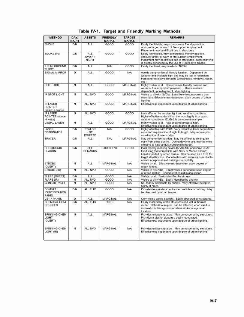
IV-7
Table IV-1. Target and Friendly Marking MethodsMETHOD DAY/
NIGHT ASSETS FRIENDLY
MARKS TARGET MARKS
REMARKS
SMOKE D/N ALL GOOD GOOD Easily identifiable, may compromise friendly position, obscure target, or warn of fire support employment. Placement may be difficult due to structures.
SMOKE (IR) D/N ALL NVD AT NIGHT
GOOD GOOD Easily identifiable, may compromise friendly position, obscure target, or warn of fire support employment. Placement may be difficult due to structures. Night marking is greatly enhanced by the use of IR reflective smoke
ILLUM, GROUND BURST
D/N ALL N/A GOOD Easily identified, may wash out NVD’s.
SIGNAL MIRROR D ALL GOOD N/A Avoids compromise of friendly location. Dependent on weather and available light and may be lost in reflections from other reflective surfaces (windshields, windows, water, etc.)
SPOT LIGHT N ALL GOOD MARGINAL Highly visible to all. Compromises friendly position and warns of fire support employment. Effectiveness is dependent upon degree of urban lighting.
IR SPOT LIGHT N ALL NVD GOOD MARGINAL Visible to all with NVG’s. Less likely to compromise than overt light. Effectiveness dependent upon degree of urban lighting.
IR LASER POINTER (below .4 watts)
N ALL NVD GOOD MARGINAL Effectiveness dependent upon degree of urban lighting.
IR LASER POINTER (above .4 watts)
N ALL NVD GOOD GOOD Less affected by ambient light and weather conditions. Highly effective under all but the most highly lit or worst weather conditions. IZLID-2 is the current example.
VISUAL LASER N ALL GOOD MARGINAL Highly visible to all. Risk of compromise is high. Effectiveness dependant upon degree of urban lighting.
LASER DESIGNATOR
D/N PGM OR LST
EQUIPED
N/A GOOD Highly effective with PGM. Very restrictive laser acquisition cone and requires line of sight to target. May require pre-coordination of laser codes
TRACER D/N ALL N/A MARGINAL May compromise position. May be difficult to distinguish mark from other gunfire. During daytime use, may be more effective to kick up dust surrounding target.
ELECTRONIC BEACON
D/N SEE REMARKS
EXCELLENT GOOD Ideal friendly marking device for AC-130 and some USAF fixed wing (not compatible with Navy or Marine aircraft). Least impeded by urban terrain. Can be used as a TRP for target identification. Coordination with aircrews essential to ensure equipment and training compatibility.
STROBE (OVERT)
N ALL MARGINAL N/A Visible by all. Effectiveness dependent upon degree of urban lighting.
STROBE (IR) N ALL NVD GOOD N/A Visible to all NVDs. Effectiveness dependent upon degree of urban lighting. Coded strobes aid in acquisition
FLARE (OVERT) D/N ALL GOOD N/A Visible by all. Easily identified by aircrew. FLARE (IR) N ALL NVD GOOD N/A Visible to all NVDs. Easily identified by aircrew. GLINT/IR PANEL N ALL NVD GOOD N/A Not readily detectable by enemy. Very effective except in
highly lit areas. COMBAT IDENTIFICATION PANEL
D/N ALL FLIR GOOD N/A Provides temperature contrast on vehicles or building. May be obscured by urban terrain.
VS-17 PANEL D ALL MARGINAL N/A Only visible during daylight. Easily obscured by structures. CHEMICAL HEAT SOURCES
D/N ALL FLIR POOR N/A Easily masked by urban structures and lost in thermal clutter. Difficult to acquire, can be effective when used to contrast cold background or when a/c knows general location.
SPINNING CHEM LIGHT (OVERT)
N ALL MARGINAL N/A Provides unique signature. May be obscured by structures. Provides a distinct signature easily recognized. Effectiveness dependent upon degree of urban lighting.
SPINNING CHEM LIGHT (IR)
N ALL NVD MARGINAL N/A Provides unique signature. May be obscured by structures. Effectiveness dependent upon degree of urban lighting.
IV-8
c. During both high and low ambient light conditions, expect to see significanturban shadowing from buildings when cultural lights are present. Shadows willhide personnel and/or vehicular targets from both the terminal guidancecontroller and the aircrew like the shadows that hide small hills against thebackground of larger mountains. Shadows will hide non-thermally significanttargets, but thermal targets still can be seen. When a combination of sensors hasto be used to acquire and identify the target, a sensor hand-off plan must bebriefed thoroughly. The use of aircraft with integrated GPS will reduce theamount of time spent finding the target area. Time permitting, inputting a targetgrid into the GPS or inertial navigation system (INS) will provide fire controlcues (range, heading, time) to the target that will aid in quicker target acquisitionand help distinguish friendly forces from enemy forces. Because CAS missionsmay involve short firing ranges, expect a minimum tracking time, and thus,minimum time to optimize the sensor.
6. Television/Electro-optical (TV/EO)
TV/EO sensors are subject to many of the same limitations as the nakedeye, particularly TV with no low light capability. Aircrews will encounterdifficulties in acquiring a target and achieving lock-on if smoke, buildings, orother urban factors repeatedly interrupt LOS. Low light or all light TV/EOsensors may require frequent gain and filter changes to accommodate varyinglight levels in urban areas. Normal means of target and friendly ID are likely toprove ineffective. IR strobes, overt strobes, and laser pointers normally visible toTV/EO sensors can be lost in the light clutter. Typical TV/EO resolution is notsufficient at medium and extended ranges to discriminate between a friendlyposition or a target and its surrounding urban features. Ground personnel needto utilize more aggressive and overt means of identifying their position and thatof the target if TV/EO sensors are to be used to identify, track and engage targetson urban terrain.
7. Electronic Beacons
Electronic beacons can be an effective tool for friendly ID in an urbanenvironment, especially when friendly troops are on the move. However, asignificant drawback to beacons is that only a few aircraft can track them. Whenother means of ID prove time consuming, a beacon may help locate a friendlyposition quickly. When a friendly ground team is on the move, no matter whetheron foot or in a vehicle, a beacon offers a good way to track the movement. WhenLOS is repeatedly interrupted, a beacon tracking radar can temporarily breaklock from the friendly position. However, when LOS is reestablished, the beacontracking radar can reacquire the friendly troops. Further, when urban terrainprevents visual contact with a friendly position, target location can be passed viareference to a beacon. If necessary, an aircraft can attack a target with nothingmore than an offset from the beacon. This method should only be employed as alast resort since it will not provide the precision normally desired in an urbanenvironment.
IV-9
8. Laser Designation
a. Background. One of the greatest challenges for an aircraft in urban terrainis achieving and maintaining LOS with a target or friendly position. Laserdesignation requires uninterrupted LOS to identify and engage a target. Rotary-wing aircraft may use their hover capabilities, but only in the most permissiveenvironments. This may mean a rotary-wing lasing platform has to be very nearthe target to keep the spot on the target until ordnance impact. Smoke fromburning buildings or other fires can drift across the laser to target line causingbeam attenuation. While this is also true on an open battlefield, urban areastypically contain more potential smoke sources than found in natural terrain.
b. Lasers. Most laser designating platforms cannot actually see their laserspot on a target. Lasers are often boresighted to other supporting sensors likeFLIR/IDS or TV/EO. If the supporting sensor cannot see a target, then the lasercannot effectively mark the target. Furthermore, although a FLIR/IDS can “see” atarget, the laser may not be capable of guiding ordnance against it since smoke,invisible to the FLIR/IDS, can effectively attenuate the laser energy. The mostimportant factor affecting FLIR performance is water vapor concentration, whichis indicated by high relative humidity, and expressed by absolute humidity. Theimpact of high water vapor concentration (indicated by high humidity) is greateron FLIR/IDS performance than its impact on laser performance. In other words,if the target can be detected with a FLIR in clear air, then the laser shouldprovide sufficient energy for seeker acquisition. As a rule of thumb, if a targetcan be detected with a supporting sensor and consistently ranged to with a laser,it is likely that the laser will designate satisfactorily for a laser-guided weapon.As an additional consideration, many targets are relatively small and can only beacquired at relatively short range. For low and medium threats, where a greatamount of time is available to use the FLIR/IDS to point the laser, targetacquisition methods are simple. As the threat escalates and the time available fortarget acquisition shrinks, targeting with the FLIR/IDS becomes more difficult.
9. Clearance to Drop/Fire for CAS Missions
a. Background. The responsibility for ordnance delivery rests with themaneuver force commander. The terminal controller has the authority to clearaircraft to release weapons after specific or general release approval from themaneuver force commander. For specific guidance see Joint Publication (JP) 3-09.3, JTTP for Close Air Support, Chapter 5. Additional references are the MTTPfound in FM 90-20, MCRP 3-16.8B, NWP 3-09.2, and AFTTP(I) 3-2.6, J-Fire,Multiservice Procedures for the Joint Application of Firepower.
b. Positive control. Positive control will be used to the maximum extentpossible. For specific guidance, refer to JP 3-09.3, Chapter 5. Additionalreferences are the MTTP found in FM 90-20, MCRP 3-16.8B, NWP 3-09.2, andAFTTP(I) 3-2.6, J-Fire, Multiservice Procedures for the Joint Application ofFirepower.
IV-10
c. Reasonable Assurance. Aircrews normally operate under positive controland receive a “cleared hot” before releasing ordnance in a CAS environment.During combat operations, low altitude flight, and deteriorating battlefieldconditions, such as communications jamming, can prevent the receipt of positiveclearance. JP 3-09.3 recommends that a joint force commander (JFC) establishguidelines that allow CAS missions to be conducted utilizing reasonableassurance. Reasonable assurance is not a routine procedure but a set of specificguidelines. It is not a “comm out” method of attack. The JFC establishes theconditions for reasonable assurance and when they will be in effect.
d. Risk-Estimate Distances. Risk-estimate distances are based onfragmentation patterns and allow the ground forces commander or combat aircommander to estimate the risk in terms of the percent of friendly casualties thatmay result from an air strike against an enemy threat along the forward line ofown troops. First and foremost, all aircrews must understand their aircraftweapons’ capabilities and limitations. Secondly, the ground commander musthave a clearly defined intent and ROE that is understood by all aircrews toensure the proper matching of weapons to targets.
10. Fixed-wing Targeting and Engagements (AV-8B, A-10, O/A-10, F-14,F-15E, F-16, F/A-18, and F-117)
a. Targeting and engagements. The standard 9 line, CAS control brief will bethe preferred method of controlling fixed-wing aircraft when conducting CAS.The available weapons suites for selected fixed-wing aircraft are shown in TableIV-2.
NOTE: The recommended probability of incapacitation (Pi) distances fromfriendly troops assumes flat open terrain, not urban terrain with buildingsfor cover and vertical structures that may mask the effects of ordnancefragment patterns. In some cases, closer delivery can be made if terrain(friendly cover) permits or if the tactical situation is urgent. The forwardair controller (FAC) shall inform the ground unit commander of the risksinvolved before commencing such a strike.

IV-11
Table IV-2. Fixed-wing Weapons SuitesAircraft M/D/S
Using Service
Ordnance Laser Capability LST | LTD
Marking Capability Beacon Capability
Other Systems
AV-8B USMC LGBs Maverick
GP Bombs CBUs
2.75” Rockets 5.00” Rockets
Napalm 25mm cannon
AGM-122 Sidearm
YES NO Rockets 25mm HEI rounds
LUU-2 Flares
None TV GPS NVG
AV-8B “Plus” USMC As Above YES NO Rockets None NVG FLIR Radar
A/OA-10A USAF Maverick GP Bombs
CBUs HE rockets
30mm cannon
YES NO WP Rockets 30mm HEI IR pointer LUU-1/2 LUU-5/6 LUU-19
M257 IR Rockets M278 Covert Rockets
None NVG
F-14 USN LGBs GP Bombs
CBUs 20mm cannon Aerial mines
NO YES Laser WP
LUU-2 Flares
None NVG Radar TGP LLTV
F-15E USAF LGBs AGM-130 GBU-15 Maverick
GP Bombs CBUs
20mm cannon
NO YES Laser 20mm HEI rounds
PPN-19 PPN-20
UPN-25/34 TPN-23/26 SST-181
X/XE PRD-78/80 SMP-1000
NVG FLIR TGP
Radar
F-16 C (less
LANTIRN)
USAF LGBs Maverick
GP Bombs CBUs
20mm cannon
YES (Some)
NO Laser (some) WP rockets
20mm HEI rounds
PPN-19 PPN-20
UPN-25/34 TPN-23/26 SST-181
X/XE PRD-78/80 SMP-1000
Radar NVG
TGP (some) SADL (some)
F-16CG (with
LANTIRN)
USAF LGBs Maverick
GP Bombs CBUs
20mm cannon
NO YES Laser WP Rockets
20mm HEI rounds
PPN-19 PPN-20
UPN-25/34 TPN-23/26 SST-181
X/XE PRD-78/80 SMP-1000
NVG FLIR TGP
Radar GPS IDM
F-16CJ USAF HARM JDAM
Maverick GP Bombs
CBUs 20mm cannon
JSOW
NO NO 20mm HEI PPN-19 PPN-20
UPN-25/34 TPN-23/26 SST-181
X/XE PRD-78/80 SMP-1000
NVG Radar GPS IDM HTS
F/A-18 USN (A/C) USMC (A/C/D)
LGBs Maverick
SLAM HARM
GP Bombs CBUs
2.75” Rockets 5.00” Rockets Napalm/FAE
20mm cannon Laser Maverick
JSOW JDAM
YES YES Laser WP Rockets HE Rockets
LUU-2 Flares 20mm HEI rounds
IR Pointer (F/A-18D only)
None FLIR GPS NVG Radar
Notes: 1. All fixed-wing aircraft shown also have aerial missiles 2. All aircraft that drop CBUs can also drop aerial mines
IV-12
b. Roles. Fixed-wing aircraft can be employed in the following roles:
(1) Offensive Counter Air (OCA),
(2) Defensive Counter Air (DCA),
(3) Strategic Attack,
(4) CAS,
(5) Interdiction,
(6) Armed Reconnaissance,
(7) Escort,
(8) Airborne FAC [FAC(A)],
(9) SEAD,
(10) Supporting Arms Coordinator, Airborne [SAC(A)].
c. Employment. Not all of the previously mentioned fixed-wing employmentmissions will be used in all urban operations. More information on OCA and DCAmissions can be found in JP 3-01, Joint Doctrine for Countering Air and MissileThreats; furthermore, strategic attack, interdiction, and escort may be found inJP 3-03, Doctrine for Joint Interdiction Operations. Lastly SEAD missions arediscussed in JP 3-01.4, Joint Suppression of Enemy Air Defenses. The fixed-wingmissions addressed in this section are armed reconnaissance, FAC(A), and CAS.
(1) Armed Reconnaissance. In the armed reconnaissance mission, thetasked aircraft take off with no assigned target to attack. Instead, they are givena designated sector. They conduct the reconnaissance in advance of groundforces. Potential targets might include reserves, logistic centers, C2 facilities,bridges, and railroads.
(2) FAC(A). The FAC(A) mission has advantages because of the potentiallyrestricted LOS that a ground FAC encounters. The FAC(A) may be able to betterposition himself to mark a target for attacking aircraft. The FAC(A) also has thesame vantage point of the target area as the attacking aircraft.
(3) CAS. Fixed-wing aircraft tasked with CAS provide timely, precision-delivered ordnance that can mean the difference between victory and defeat.CAS has a devastating effect upon the enemy. Both his morale and will to fightare affected. Target acquisition and location will be the most difficult aspects ofurban fixed-wing CAS.
IV-13
11. Fixed-wing Targeting and Engagements (AC-130)
a. Background. In a typical AC-130 CAS mission, the aircraft places fireagainst targets in close proximity to friendly forces. CAS engagement distancesmay be reduced to “danger close,” which is that distance producing a 0.1 percentPi based on USAF 61A1-3-4, JMEM data. For the AC-130’s weapons, danger closeis 200 meters (m) for the 105 millimeter (mm) and 125 m for the 40mm and 25mm.For engagements inside danger close, the ground commander must acceptresponsibility for the increased potential for injury to his troops. Engagementson urban terrain may be well inside danger close distances. In fact, many may beat less than 50 m.
b. Marking Friendly Forces. The most important step in any CAS engagementis to locate the friendly forces. This is doctrinally accomplished with some type ofmarking that can be seen visually from the aircraft or observed using the aircraftsensors. In an urban environment, the ambient lighting may obscure the marking.This makes some other form of marking necessary, such as IR sensors orelectronic beacons.
(1) IR Sensors. IR chemlights, MRE heaters, space blankets, andtemperature absorbing panels provide markings significant to IDS or low lightlevel TV systems.
(2) Electronic Beacons. The currently fielded PPN-19 radar beacon is largeand heavy, making it burdensome for lightly equipped, fast moving troops.However, a new micro-transponder, the smaller selectable strike (SST)-201, isbeing fielded to provide a usable radar beacon that is lightweight and easilyemployed. This capability can be used to locate the friendly forces and orient thesensors to the target for a direct engagement. It can also be used as a fire controloffset to engage the target.
c. Locating the Target. Locating the target usually is accomplished bylocating the friendly forces first. From the friendly location, a bearing and rangeoffset is often used to orient the AC-130 to the target area. From the targetdescription, the gunship attempts to positively identify the target. In urbanterrain, a detailed talk-on with reference points expedites target acquisition.Another very effective technique is for the friendly team to designate the targetwith an IR target designator, like the laser pointer long range (LPL)-30. This isthe most expeditious and accurate method of target confirmation. Again, ambientlights in the urban environment may obscure the marker. The HC-130H gunshipis equipped with an infrared zoom laser illuminator designator (IZLID) to aid intarget confirmation. The gated laser illuminator casts a very large and diffusedIR spot on the target area. Whatever the method, target confirmation is crucialto eliminate fratricide and collateral damage.
d. Roles. The AC-130H/U is ideally suited for fire support in low threat urbanenvironments. Within permissive environments, the AC-130H/U is effective inthe following roles:
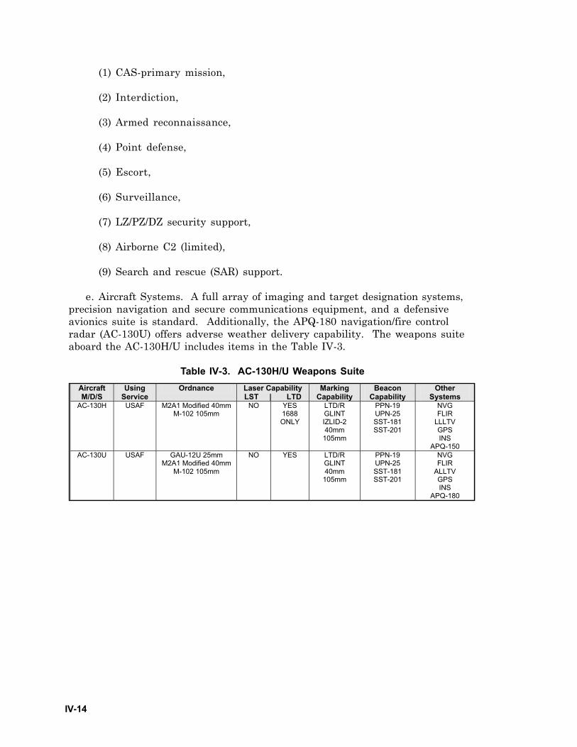
IV-14
Aircraft M/D/S
Using Service
Ordnance Laser Capability LST | LTD
Marking Capability
Beacon Capability
Other Systems
AC-130H USAF M2A1 Modified 40mm M-102 105mm
NO YES 1688 ONLY
LTD/R GLINT IZLID-2 40mm
105mm
PPN-19 UPN-25 SST-181 SST-201
NVG FLIR
LLLTV GPS INS
APQ-150 AC-130U USAF GAU-12U 25mm
M2A1 Modified 40mm M-102 105mm
NO YES LTD/R GLINT 40mm
105mm
PPN-19 UPN-25 SST-181 SST-201
NVG FLIR
ALLTV GPS INS
APQ-180
(1) CAS-primary mission,
(2) Interdiction,
(3) Armed reconnaissance,
(4) Point defense,
(5) Escort,
(6) Surveillance,
(7) LZ/PZ/DZ security support,
(8) Airborne C2 (limited),
(9) Search and rescue (SAR) support.
e. Aircraft Systems. A full array of imaging and target designation systems,precision navigation and secure communications equipment, and a defensiveavionics suite is standard. Additionally, the APQ-180 navigation/fire controlradar (AC-130U) offers adverse weather delivery capability. The weapons suiteaboard the AC-130H/U includes items in the Table IV-3.
Table IV-3. AC-130H/U Weapons Suite
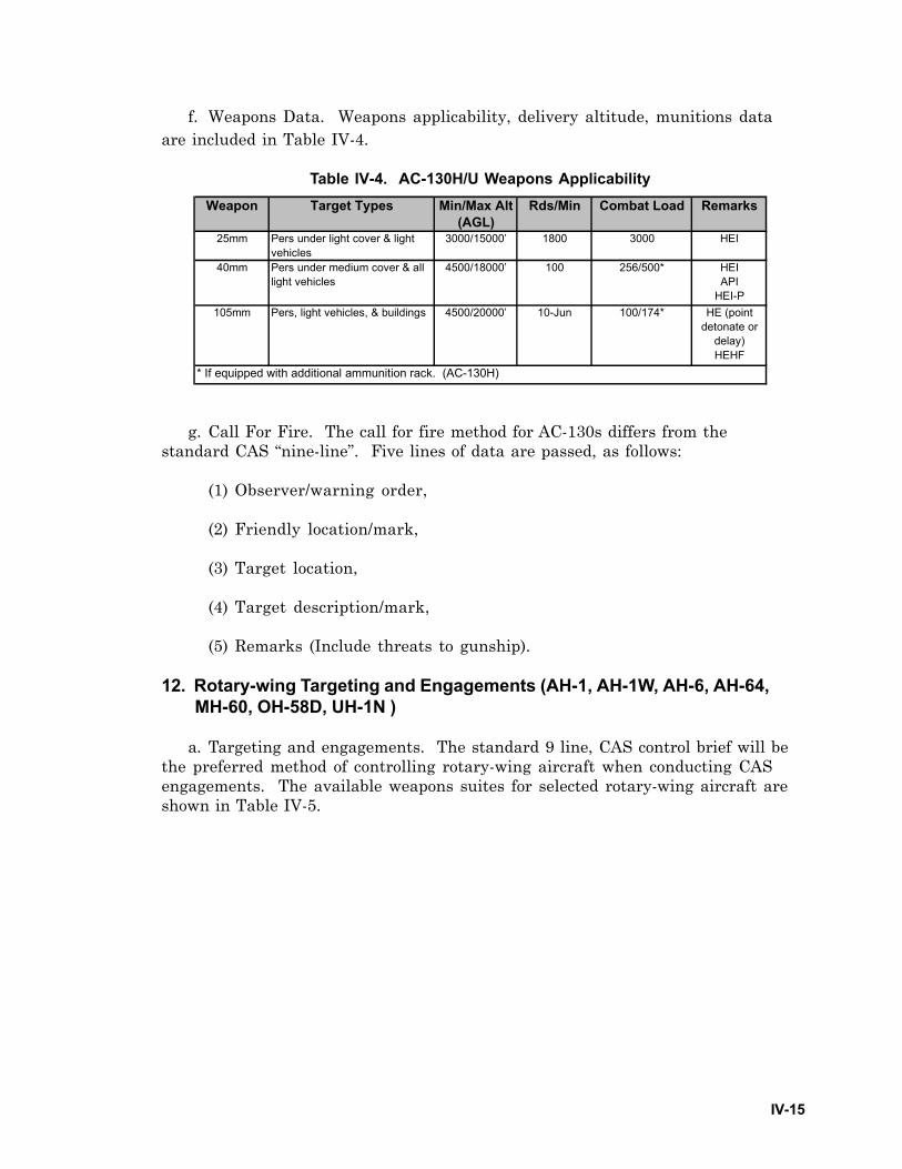
IV-15
f. Weapons Data. Weapons applicability, delivery altitude, munitions dataare included in Table IV-4.
Table IV-4. AC-130H/U Weapons Applicability
g. Call For Fire. The call for fire method for AC-130s differs from thestandard CAS “nine-line”. Five lines of data are passed, as follows:
(1) Observer/warning order,
(2) Friendly location/mark,
(3) Target location,
(4) Target description/mark,
(5) Remarks (Include threats to gunship).
12. Rotary-wing Targeting and Engagements (AH-1, AH-1W, AH-6, AH-64,MH-60, OH-58D, UH-1N )
a. Targeting and engagements. The standard 9 line, CAS control brief will bethe preferred method of controlling rotary-wing aircraft when conducting CASengagements. The available weapons suites for selected rotary-wing aircraft areshown in Table IV-5.
Weapon Target Types Min/Max Alt (AGL)
Rds/Min Combat Load Remarks
25mm Pers under light cover & light vehicles
3000/15000’ 1800 3000 HEI
40mm Pers under medium cover & all light vehicles
4500/18000’ 100 256/500* HEIAPI
HEI-P105mm Pers, light vehicles, & buildings 4500/20000’ 10-Jun 100/174* HE (point
detonate or delay)HEHF
* If equipped with additional ammunition rack. (AC-130H)
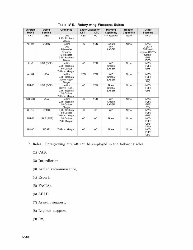
IV-16
Table IV-5. Rotary-wing Weapons Suites
b. Roles. Rotary-wing aircraft can be employed in the following roles:
(1) CAS,
(2) Interdiction,
(3) Armed reconnaissance,
(4) Escort,
(5) FAC(A),
(6) SEAD,
(7) Assault support,
(8) Logistic support,
(9) C2,
Aircraft M/D/S
Using Service
Ordnance Laser Capability LST | LTD
Marking Capability
Beacon Capability
Other Systems
AH-1 USA TOW 2.75” Rockets
20mm
YES NO WP Rockets
None NVG
AH-1W USMC Hellfire TOW
Sidewinder Sidearm
5” Rockets 2.75” Rockets
20mm
NO YES Rockets WP
LASER
None NVG CCDTV
FLIR (with organic CCDTV
system) GPS DVO
AH-6 USA (SOF) Hellfire 2.75” Rockets
.50 Caliber 7.62mm Minigun
NO YES WP Smoke LASER
None NVG FLIR GPS
AH-64 USA Hellfire
2.75” Rockets 30mm HEDP
Stinger
YES YES WP Smoke LASER
None NVG FLIR GPS DTV
MH-60 USA (SOF) Hellfire 30mm HEDP 2.75” Rockets
.50 Caliber 7.62mm Minigun
NO YES None Smoke LASER
None NVG FLIR GPS
OH-58D USA Hellfire 2.75” Rockets
.50 Caliber Stinger
NO YES WP Smoke LASER
None NVG FLIR GPS DTV
UH-1N USMC 2.75” Rockets .50 Caliber
7.62mm minigun
NO NO WP None NVG FLIR GPS
MH-53 USAF (SOF) .50 Caliber 7.62 Minigun
NO NO None None NVG FLIR GPS TFTA
HH-60 USAF 7.62mm Minigun NO NO None None NVG FLIR GPS

IV-17
(10) Combat SAR (CSAR),
(11) Airmobile assault,
(12) Medical evacuation (MEDEVAC).
c. Running/diving fire. Rotary-wing aircraft should make running and divingfire engagements along corridors of visibility. These engagements requirecontinuous movement to minimize exposure time. Before unmasking, all weaponsshould be configured and armed. In situations where only one aircraft at a time isin a position to engage, the lead aircraft fires as soon as possible after achieving afiring solution, then a break turn is made toward masking terrain immediatelyafter firing. The wingman provides suppression when lead makes the break.Avoid flight into other target visibility corridors during the egress. Re-attacksshould be from alternate directions to avoid predictability. (Figure IV-5)
LOW ALTITUDEVISIBILITY CORRIDORS
BREAK TURN TOWARDMASKING TERRAIN
EGRESS ORMANEUVER FORRE-ATTACKFROM NEWDIRECTION
ARMAMENT SWITCHESSET PRIOR TO TURNINGTO ATTACK HEADING
ATTACK RUN
Figure IV-5. Running/Diving Fire Engagement
d. Hover Fire. Hovering fire engagements are not recommended, but may bemade. The normal considerations apply for the selection of firing positions.Buildings and structures, which offer cover and concealment from the target area,are treated like natural terrain. It must again be emphasized, however, that allurban features are potential enemy positions. Features selected for verticalunmasking should not be significantly taller than surrounding structures. Theyshould be selected to provide target visibility at the lowest possible altitude.Many rotary-wing engagements will be conducted at very close ranges (<500m),often inside the minimum range for the Hellfire missile. At such close ranges, useof the cannon is highly recommended. Minimize the time spent stationary in theposition. Plan multiple firing points and egress routes providing maximum coverand concealment. (Figure IV-6) Second to enemy fire, wire and tower obstacleswill present the biggest hazard to flight when pulling off a target run in the urbanenvironment.
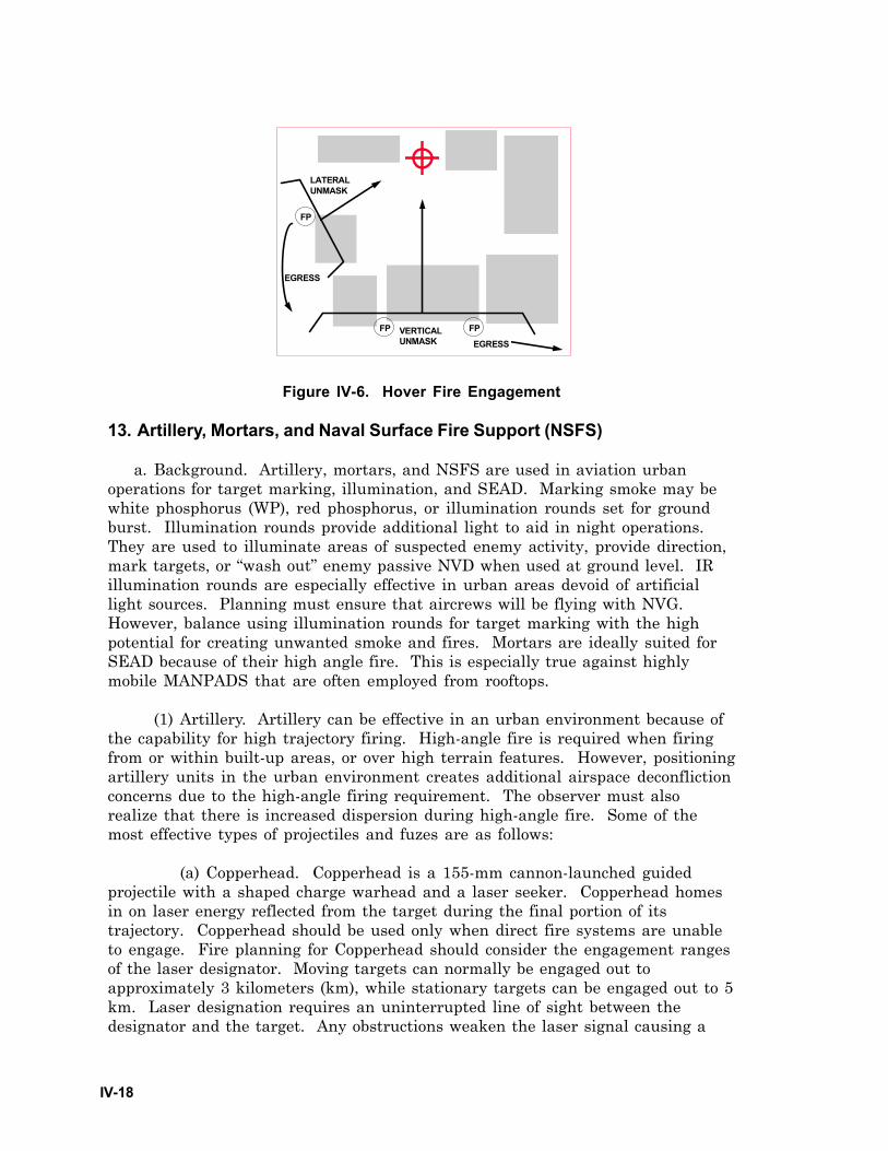
IV-18
LATERALUNMASK
VERTICALUNMASK EGRESS
FP FP
FP
EGRESS
Figure IV-6. Hover Fire Engagement
13. Artillery, Mortars, and Naval Surface Fire Support (NSFS)
a. Background. Artillery, mortars, and NSFS are used in aviation urbanoperations for target marking, illumination, and SEAD. Marking smoke may bewhite phosphorus (WP), red phosphorus, or illumination rounds set for groundburst. Illumination rounds provide additional light to aid in night operations.They are used to illuminate areas of suspected enemy activity, provide direction,mark targets, or “wash out” enemy passive NVD when used at ground level. IRillumination rounds are especially effective in urban areas devoid of artificiallight sources. Planning must ensure that aircrews will be flying with NVG.However, balance using illumination rounds for target marking with the highpotential for creating unwanted smoke and fires. Mortars are ideally suited forSEAD because of their high angle fire. This is especially true against highlymobile MANPADS that are often employed from rooftops.
(1) Artillery. Artillery can be effective in an urban environment because ofthe capability for high trajectory firing. High-angle fire is required when firingfrom or within built-up areas, or over high terrain features. However, positioningartillery units in the urban environment creates additional airspace deconflictionconcerns due to the high-angle firing requirement. The observer must alsorealize that there is increased dispersion during high-angle fire. Some of themost effective types of projectiles and fuzes are as follows:
(a) Copperhead. Copperhead is a 155-mm cannon-launched guidedprojectile with a shaped charge warhead and a laser seeker. Copperhead homesin on laser energy reflected from the target during the final portion of itstrajectory. Copperhead should be used only when direct fire systems are unableto engage. Fire planning for Copperhead should consider the engagement rangesof the laser designator. Moving targets can normally be engaged out toapproximately 3 kilometers (km), while stationary targets can be engaged out to 5km. Laser designation requires an uninterrupted line of sight between thedesignator and the target. Any obstructions weaken the laser signal causing a
IV-19
decrease in the performance of the Copperhead round. Copperhead engagementsmust be carefully analyzed for effects of the gun-target line, observer-target line,and masking effects of surrounding structures during the terminal guidancephase of trajectory.
(b) Delay fuzing. Required for penetration of reinforced or hardenedrooftops.
(c) Variable time (VT) fusing. Required for an airburst. Effective inclearing rooftops, but has greater potential for collateral damage.
(2) Mortars. Mortars are generally very effective in urban terrain due totheir high angle trajectories. Several systems are available depending on theground units involved in the operation. These systems include:
(a) 60-mm Mortar. The (M224) 60-mm mortar is in Army airborne, airassault, light infantry, and ranger companies and all Marine rifle companies. Thecurrent family of ammunition consists of high explosive (HE), smoke,illumination, and IR illumination.
(b) 81-mm Mortar. The (M252) 81-mm mortar is in all Marine infantry,and Army light battalions. The current family of ammunition consists of HE,smoke (Red phosphorus), illumination, and IR illumination.
(c) 120-mm Mortar. The 120-mm mortar is fielded in a heavy Armybattalion. The current family of ammunition consists of HE, smoke, andillumination, and IR Illumination.
(3) NSFS. When available, NSFS provides effective fire support to forcesoperating near coastal waters. However, equipment limitations, enemyelectronic warfare, and unfavorable atmospheric conditions can interrupt radiocommunications to control NSFS. Naval guns are not normally suitable for high-angle fire because of their high muzzle velocity.
(a) NSFS ships normally remain under control of the Commander,Amphibious Task Force (CATF). Ship positioning and method of delivery remainwith the ship captain. When the ships are threatened, the target-attackpriorities of the ship may cause it to hold or cancel land force fire missions untilthe threat is removed.
(b) NSFS ships are normally assigned one of two missions: directsupport or general support. A ship in direct support delivers both planned andon-call fires. General support missions are assigned to ships supporting forces ofbrigade size and larger. The supported force selects the targets, the timing offires, and the method of adjustment of fires.
(c) NSFS has a variety of weapons ranging from conventional armamentto missiles. NSFS ships also have a large variety of ammunition and high rates of
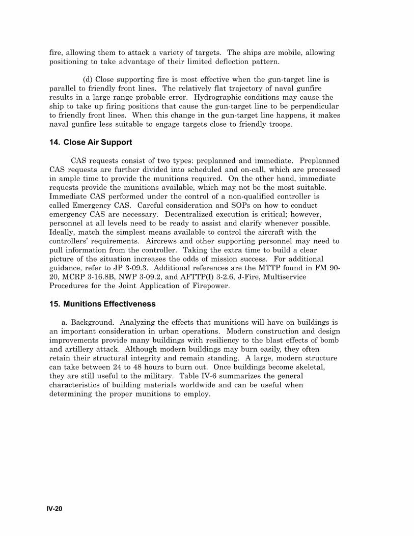
IV-20
fire, allowing them to attack a variety of targets. The ships are mobile, allowingpositioning to take advantage of their limited deflection pattern.
(d) Close supporting fire is most effective when the gun-target line isparallel to friendly front lines. The relatively flat trajectory of naval gunfireresults in a large range probable error. Hydrographic conditions may cause theship to take up firing positions that cause the gun-target line to be perpendicularto friendly front lines. When this change in the gun-target line happens, it makesnaval gunfire less suitable to engage targets close to friendly troops.
14. Close Air Support
CAS requests consist of two types: preplanned and immediate. PreplannedCAS requests are further divided into scheduled and on-call, which are processedin ample time to provide the munitions required. On the other hand, immediaterequests provide the munitions available, which may not be the most suitable.Immediate CAS performed under the control of a non-qualified controller iscalled Emergency CAS. Careful consideration and SOPs on how to conductemergency CAS are necessary. Decentralized execution is critical; however,personnel at all levels need to be ready to assist and clarify whenever possible.Ideally, match the simplest means available to control the aircraft with thecontrollers’ requirements. Aircrews and other supporting personnel may need topull information from the controller. Taking the extra time to build a clearpicture of the situation increases the odds of mission success. For additionalguidance, refer to JP 3-09.3. Additional references are the MTTP found in FM 90-20, MCRP 3-16.8B, NWP 3-09.2, and AFTTP(I) 3-2.6, J-Fire, MultiserviceProcedures for the Joint Application of Firepower.
15. Munitions Effectiveness
a. Background. Analyzing the effects that munitions will have on buildings isan important consideration in urban operations. Modern construction and designimprovements provide many buildings with resiliency to the blast effects of bomband artillery attack. Although modern buildings may burn easily, they oftenretain their structural integrity and remain standing. A large, modern structurecan take between 24 to 48 hours to burn out. Once buildings become skeletal,they are still useful to the military. Table IV-6 summarizes the generalcharacteristics of building materials worldwide and can be useful whendetermining the proper munitions to employ.
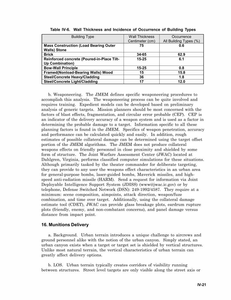
IV-21
Table IV-6. Wall Thickness and Incidence of Occurrence of Building Types
b. Weaponeering. The JMEM defines specific weaponeering procedures toaccomplish this analysis. The weaponeering process can be quite involved andrequires training. Expedient models can be developed based on preliminaryanalysis of generic targets. Mission planners should be most concerned with thefactors of blast effects, fragmentation, and circular error probable (CEP). CEP isan indicator of the delivery accuracy of a weapon system and is used as a factor indetermining the probable damage to a target. Information specific to all theseplanning factors is found in the JMEM. Specifics of weapon penetration, accuracyand performance can be calculated quickly and easily. In addition, roughestimates of possible collateral damage can be determined using the target offsetportion of the JMEM algorithms. The JMEM does not produce collateralweapons effects on friendly personnel in close proximity and shielded by someform of structure. The Joint Warfare Assessment Center (JWAC) located atDahlgren, Virginia, performs classified computer simulations for these situations.Although primarily tasked by the theater commander for deliberate targeting,they can provide to any user the weapons effect characteristics in an urban areafor general-purpose bombs, laser-guided bombs, Maverick missiles, and high-speed anti-radiation missile (HARM). Send a request for information via JointDeployable Intelligence Support System (JDISS) ([email protected]) or bytelephone, Defense Switched Network (DSN): 249-1992/4587. They require at aminimum: scene composition, aimpoints, attack direction, weapon/fuzecombination, and time over target. Additionally, using the collateral damageestimate tool (CDET), JWAC can provide glass breakage plots, eardrum ruptureplots (friendly, enemy, and non-combatant concerns), and panel damage versusdistance from impact point.
16. Munitions Delivery
a. Background. Urban terrain introduces a unique challenge to aircrews andground personnel alike with the notion of the urban canyon. Simply stated, anurban canyon exists when a target or target set is shielded by vertical structures.Unlike most natural terrain, the vertical characteristics of urban terrain cangreatly affect delivery options.
b. LOS. Urban terrain typically creates corridors of visibility runningbetween structures. Street level targets are only visible along the street axis or
Building Type Wall Thickness Centimeter (cm)
Occurrence All Building Types (%)
Mass Construction (Load Bearing Outer Walls) Stone
75 0.6
Brick 34-65 62.9 Reinforced concrete (Poured-in-Place Tilt-Up Combination)
15-25 6.1
Bow-Wall Principle 15-25 0.8 Framed(Nonload-Bearing Walls) Wood 15 15.8 Steel/Concrete Heavy/Cladding 36 1.8 Steel/Concrete Light/Cladding 17 12.0
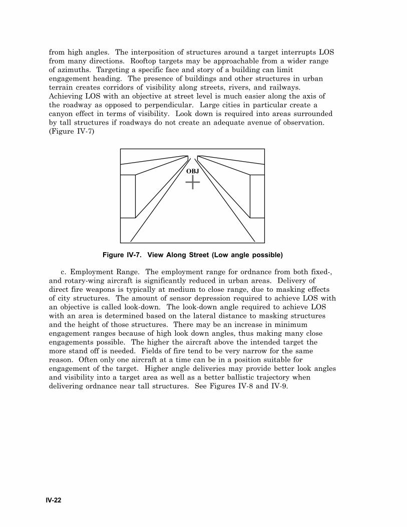
IV-22
from high angles. The interposition of structures around a target interrupts LOSfrom many directions. Rooftop targets may be approachable from a wider rangeof azimuths. Targeting a specific face and story of a building can limitengagement heading. The presence of buildings and other structures in urbanterrain creates corridors of visibility along streets, rivers, and railways.Achieving LOS with an objective at street level is much easier along the axis ofthe roadway as opposed to perpendicular. Large cities in particular create acanyon effect in terms of visibility. Look down is required into areas surroundedby tall structures if roadways do not create an adequate avenue of observation.(Figure IV-7)
OBJ
Figure IV-7. View Along Street (Low angle possible)
c. Employment Range. The employment range for ordnance from both fixed-,and rotary-wing aircraft is significantly reduced in urban areas. Delivery ofdirect fire weapons is typically at medium to close range, due to masking effectsof city structures. The amount of sensor depression required to achieve LOS withan objective is called look-down. The look-down angle required to achieve LOSwith an area is determined based on the lateral distance to masking structuresand the height of those structures. There may be an increase in minimumengagement ranges because of high look down angles, thus making many closeengagements possible. The higher the aircraft above the intended target themore stand off is needed. Fields of fire tend to be very narrow for the samereason. Often only one aircraft at a time can be in a position suitable forengagement of the target. Higher angle deliveries may provide better look anglesand visibility into a target area as well as a better ballistic trajectory whendelivering ordnance near tall structures. See Figures IV-8 and IV-9.
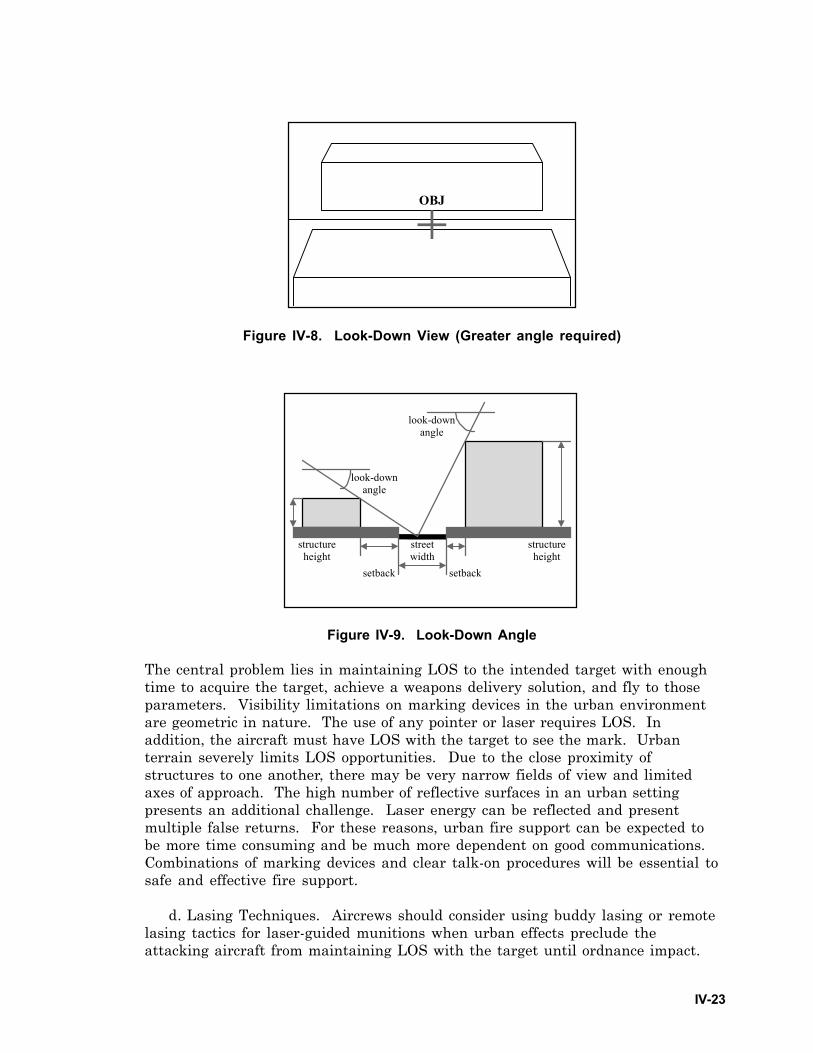
IV-23
OBJ
Figure IV-8. Look-Down View (Greater angle required)
street width
setback setback
structure height
structure height
look-down angle
look-down angle
Figure IV-9. Look-Down Angle
The central problem lies in maintaining LOS to the intended target with enoughtime to acquire the target, achieve a weapons delivery solution, and fly to thoseparameters. Visibility limitations on marking devices in the urban environmentare geometric in nature. The use of any pointer or laser requires LOS. Inaddition, the aircraft must have LOS with the target to see the mark. Urbanterrain severely limits LOS opportunities. Due to the close proximity ofstructures to one another, there may be very narrow fields of view and limitedaxes of approach. The high number of reflective surfaces in an urban settingpresents an additional challenge. Laser energy can be reflected and presentmultiple false returns. For these reasons, urban fire support can be expected tobe more time consuming and be much more dependent on good communications.Combinations of marking devices and clear talk-on procedures will be essential tosafe and effective fire support.
d. Lasing Techniques. Aircrews should consider using buddy lasing or remotelasing tactics for laser-guided munitions when urban effects preclude theattacking aircraft from maintaining LOS with the target until ordnance impact.
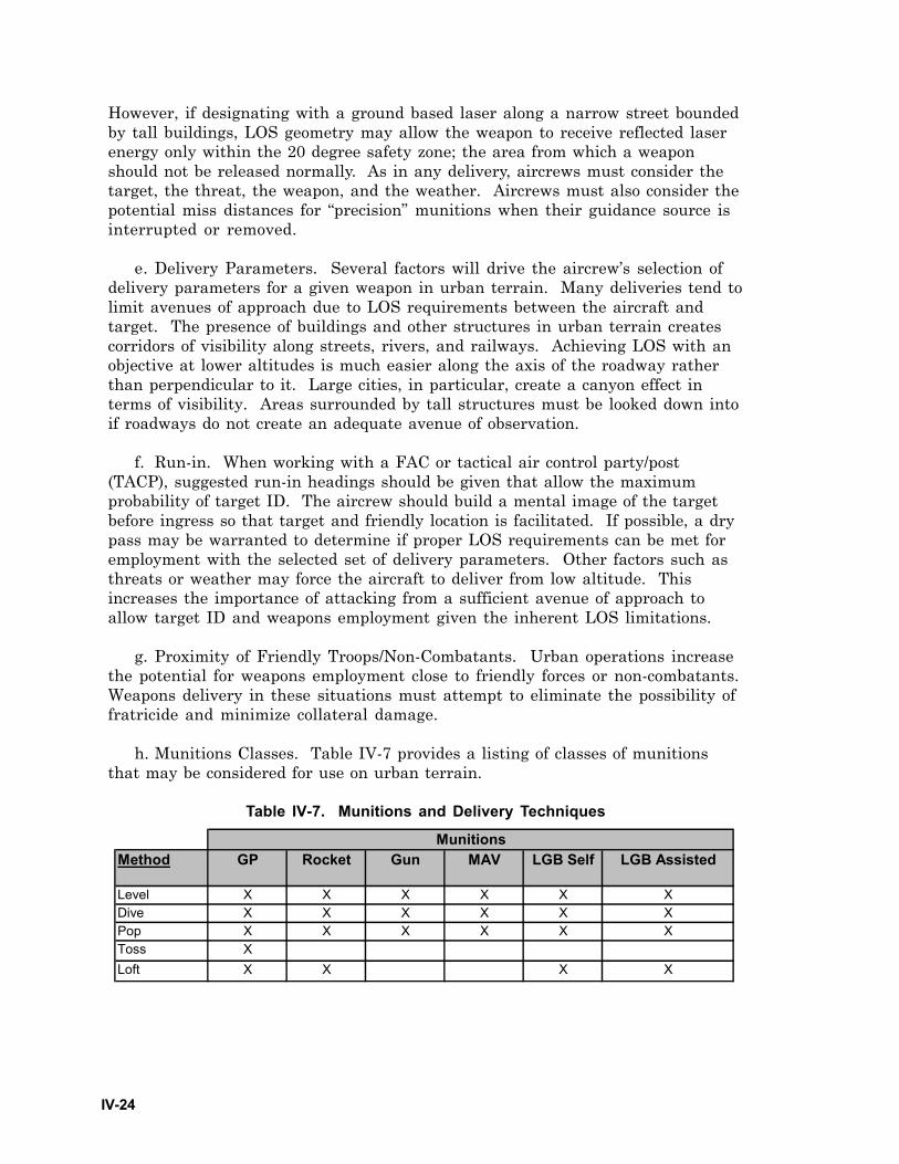
IV-24
Method GP Rocket Gun MAV LGB Self LGB Assisted
Level X X X X X XDive X X X X X XPop X X X X X XToss XLoft X X X X
Munitions
However, if designating with a ground based laser along a narrow street boundedby tall buildings, LOS geometry may allow the weapon to receive reflected laserenergy only within the 20 degree safety zone; the area from which a weaponshould not be released normally. As in any delivery, aircrews must consider thetarget, the threat, the weapon, and the weather. Aircrews must also consider thepotential miss distances for “precision” munitions when their guidance source isinterrupted or removed.
e. Delivery Parameters. Several factors will drive the aircrew’s selection ofdelivery parameters for a given weapon in urban terrain. Many deliveries tend tolimit avenues of approach due to LOS requirements between the aircraft andtarget. The presence of buildings and other structures in urban terrain createscorridors of visibility along streets, rivers, and railways. Achieving LOS with anobjective at lower altitudes is much easier along the axis of the roadway ratherthan perpendicular to it. Large cities, in particular, create a canyon effect interms of visibility. Areas surrounded by tall structures must be looked down intoif roadways do not create an adequate avenue of observation.
f. Run-in. When working with a FAC or tactical air control party/post(TACP), suggested run-in headings should be given that allow the maximumprobability of target ID. The aircrew should build a mental image of the targetbefore ingress so that target and friendly location is facilitated. If possible, a drypass may be warranted to determine if proper LOS requirements can be met foremployment with the selected set of delivery parameters. Other factors such asthreats or weather may force the aircraft to deliver from low altitude. Thisincreases the importance of attacking from a sufficient avenue of approach toallow target ID and weapons employment given the inherent LOS limitations.
g. Proximity of Friendly Troops/Non-Combatants. Urban operations increasethe potential for weapons employment close to friendly forces or non-combatants.Weapons delivery in these situations must attempt to eliminate the possibility offratricide and minimize collateral damage.
h. Munitions Classes. Table IV-7 provides a listing of classes of munitionsthat may be considered for use on urban terrain.
Table IV-7. Munitions and Delivery Techniques
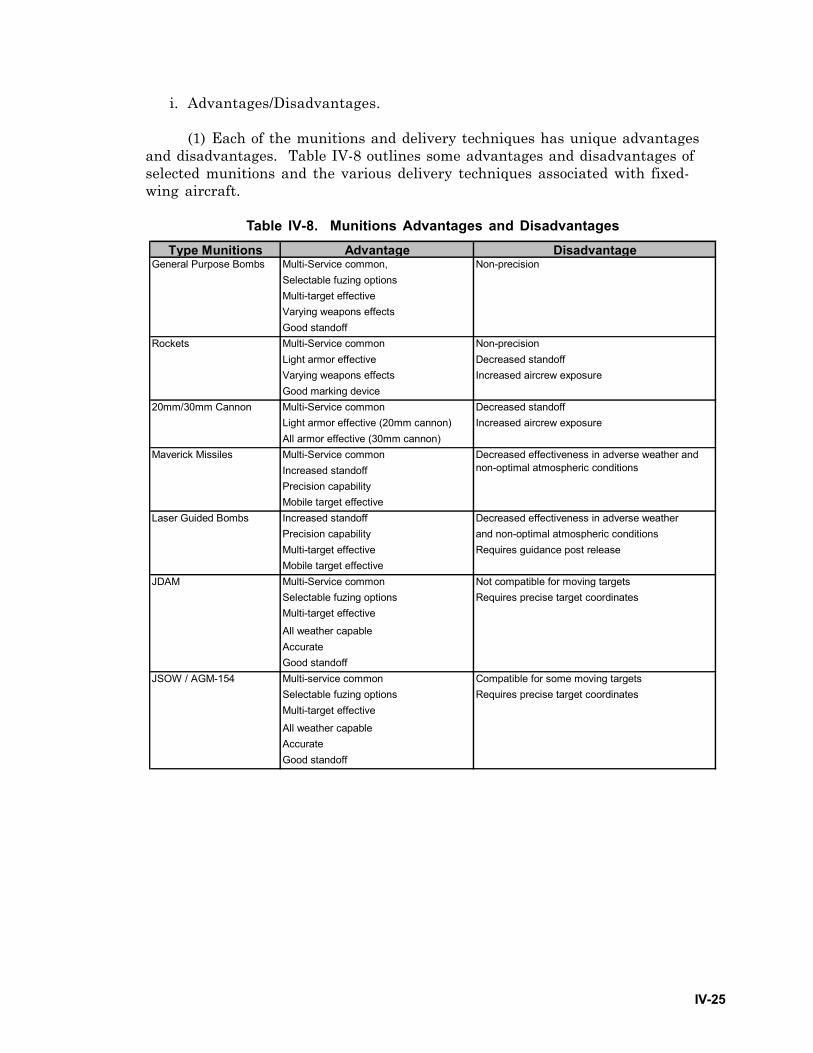
IV-25
i. Advantages/Disadvantages.
(1) Each of the munitions and delivery techniques has unique advantagesand disadvantages. Table IV-8 outlines some advantages and disadvantages ofselected munitions and the various delivery techniques associated with fixed-wing aircraft.
Table IV-8. Munitions Advantages and DisadvantagesType Munitions Advantage Disadvantage
Multi-Service common,Selectable fuzing optionsMulti-target effectiveVarying weapons effectsGood standoffMulti-Service common Non-precisionLight armor effective Decreased standoffVarying weapons effects Increased aircrew exposureGood marking deviceMulti-Service common Decreased standoffLight armor effective (20mm cannon) Increased aircrew exposureAll armor effective (30mm cannon)Multi-Service commonIncreased standoffPrecision capabilityMobile target effectiveIncreased standoff Decreased effectiveness in adverse weatherPrecision capability and non-optimal atmospheric conditionsMulti-target effective Requires guidance post releaseMobile target effectiveMulti-Service common Not compatible for moving targetsSelectable fuzing options Requires precise target coordinatesMulti-target effective
All weather capableAccurateGood standoffMulti-service common Compatible for some moving targetsSelectable fuzing options Requires precise target coordinatesMulti-target effective
All weather capableAccurateGood standoff
JDAM
JSOW / AGM-154
20mm/30mm Cannon
Maverick Missiles Decreased effectiveness in adverse weather and non-optimal atmospheric conditions
Laser Guided Bombs
General Purpose Bombs Non-precision
Rockets
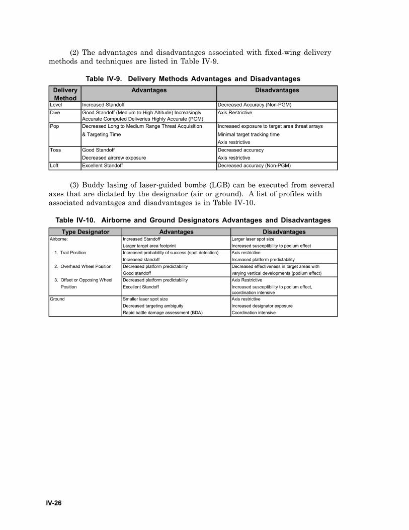
IV-26
Delivery Method
Advantages Disadvantages
Level Increased Standoff Decreased Accuracy (Non-PGM)Dive Good Standoff (Medium to High Altitude) Increasingly
Accurate Computed Deliveries Highly Accurate (PGM)Axis Restrictive
Pop Decreased Long to Medium Range Threat Acquisition Increased exposure to target area threat arrays& Targeting Time Minimal target tracking time
Axis restrictiveGood Standoff Decreased accuracyDecreased aircrew exposure Axis restrictive
Loft Excellent Standoff Decreased accuracy (Non-PGM)
Toss
Type Designator Advantages DisadvantagesIncreased Standoff Larger laser spot sizeLarger target area footprint Increased susceptibility to podium effectIncreased probability of success (spot detection) Axis restrictiveIncreased standoff Increased platform predictability
2. Overhead Wheel Position Decreased platform predictability Decreased effectiveness in target areas with Good standoff varying vertical developments (podium effect)
3. Offset or Opposing Wheel Decreased platform predictability Axis Restrictive Position Excellent Standoff Increased susceptibility to podium effect,
coordination intensiveSmaller laser spot size Axis restrictive Decreased targeting ambiguity Increased designator exposureRapid battle damage assessment (BDA) Coordination intensive
Airborne:
1. Trail Position
Ground
(2) The advantages and disadvantages associated with fixed-wing deliverymethods and techniques are listed in Table IV-9.
Table IV-9. Delivery Methods Advantages and Disadvantages
(3) Buddy lasing of laser-guided bombs (LGB) can be executed from severalaxes that are dictated by the designator (air or ground). A list of profiles withassociated advantages and disadvantages is in Table IV-10.
Table IV-10. Airborne and Ground Designators Advantages and Disadvantages
A-1
Appendix A
AIR MISSION PLANNING GUIDELINES
The following items are areas to review during mission planning. While thesetopics may be common, they have increased applicability to aviation urbanoperations.
1. Mission Analysis
a. Determine restrictions and constraints.
b. Determine number of aircraft required to accomplish mission (minimize, ifpossible).
c. Update information before takeoff, en route, and as often as necessaryduring the mission (urban air operations can become very fluid).
2. Conduct Risk Assessment and Management
3. Friendly Situation
a. Obtain current information regarding friendly forces.
b. Analyze the concept of operations.
4. Threat
a. Know enemy capabilities and limitations.
b. Review known enemy positions.
5. Terrain Analysis
a. Perform flight hazards assessment, physical and environmental.
b. Determine dominant terrain/structures.
c. Determine surface mobility, above ground, street level, and subterranean.
d. Determine degree of terrain relief and variations in building height.
6. Weather
a. Evaluate weather and illumination data.
b. Evaluate enemy’s weather capabilities.
A-2
7. Route Planning and Navigation
a. Plan ingress, egress, and contingency routes to minimize the duration offlight over urban terrain.
b. Use alternate flight routes, be unpredictable. (Urban operations tend tooveruse routes)
8. Terminal Area Procedures
a. Plan terminal area actions in detail (airfields, HLZs, PZs, DZs, etc.).
b. Determine the effects of weather (urban specific) and enemy positions.
9. Communications
a. Determine communications limitations between aircrew and ground forces.
b. Include visual signals.
c. Create a solid alternate communications plan.
10. Airspace Control
a. Know the controlling agencies and required procedures.
b. Request additional measures as required.
11. Rules of Engagement
a. Ensure identification, friend, or foe (IFF) and aircraft survivabilityequipment (ASE) is working.
b. Understand the purpose and demarcation lines for IFF and ASE. (morecomplicated in urban operations)
12. Weapons Selection and Employment
a. Clearly mark and confirm targets; know forbidden targets.
b. Ensure a common reference system is used.
13. Contingencies
Develop plans for casualties, personnel recovery (PR) (Appendix D),communications, navigation, weapons, and aircraft systems.
B-1
Appendix B
JOINT INTELLIGENCE PREPARATION OF THE BATTLESPACE
1. Process
a. The JIPB process assists in planning aviation urban operations. Theprocess in JP 2-01.3, JTTP for Joint Intelligence Preparation of the Battlespace, 2nd
Draft, 1 Feb 98, is used to produce intelligence assessments, estimates, and otherintelligence products supporting decision making process. All forces must have athorough understanding of the process.
b. The varied nature of the threats in urban operations requires liaison withlocal police, militia, NGO, etc., to acquire the information needed for JIPB andmission planning. JIPB is a continuous process involving four major steps:
(1) Defining the total battlespace environment,
(2) Describing the battlespace’s effects,
(3) Evaluating the adversary,
(4) Determining and describing the adversary’s potential courses of action(COA), most likely COA, and the COA most dangerous to friendly forces andmission accomplishment.
c. The JIPB process is used to analyze the environment and determine anadversary’s capabilities to operate within it. JIPB products are used by staffs toprepare their estimates. They are applied during the analysis and selection of afriendly COA. The size and location of the battlespace, objectives, avenues ofapproach, effects of weather and terrain, and the COA of adversary forces aresome of the areas of information required for urban operations addressed in thisprocess. Initial JIPB for aviation must orient aircrews for operations in clutteredurban terrain. The type of urban terrain, the availability of information andcollection sources, and the type of operations being conducted affect the amountof information on threat forces of significant military factors in an urban area.Urban operations may require greater use of information derived from HUMINT.The JIPB process should provide aircrews imagery and target overlaysfacilitating all mission types. Aircrews must carefully review applicable productsensuring they satisfy mission requirements. Further information on theintelligence preparation of the battlespace (IPB) process is found in the following:
(1) FM 34-130, Intelligence Preparation of the Battlefield.
(2) White Paper, Air Force Preparation of the Battlespace, 16 Feb 99.
d. A thorough JIPB process including a map and photoreconnaissance reviewprepares aircrews before mission execution. Upon mission receipt, aircrewsshould request the necessary maps and intelligence products. Aerial imagery is
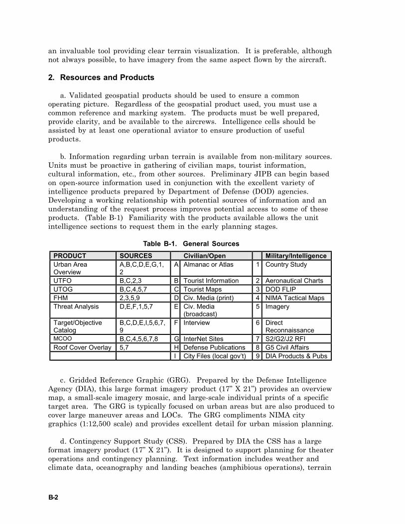
B-2
an invaluable tool providing clear terrain visualization. It is preferable, althoughnot always possible, to have imagery from the same aspect flown by the aircraft.
2. Resources and Products
a. Validated geospatial products should be used to ensure a commonoperating picture. Regardless of the geospatial product used, you must use acommon reference and marking system. The products must be well prepared,provide clarity, and be available to the aircrews. Intelligence cells should beassisted by at least one operational aviator to ensure production of usefulproducts.
b. Information regarding urban terrain is available from non-military sources.Units must be proactive in gathering of civilian maps, tourist information,cultural information, etc., from other sources. Preliminary JIPB can begin basedon open-source information used in conjunction with the excellent variety ofintelligence products prepared by Department of Defense (DOD) agencies.Developing a working relationship with potential sources of information and anunderstanding of the request process improves potential access to some of theseproducts. (Table B-1) Familiarity with the products available allows the unitintelligence sections to request them in the early planning stages.
Table B-1. General Sources
c. Gridded Reference Graphic (GRG). Prepared by the Defense IntelligenceAgency (DIA), this large format imagery product (17” X 21”) provides an overviewmap, a small-scale imagery mosaic, and large-scale individual prints of a specifictarget area. The GRG is typically focused on urban areas but are also produced tocover large maneuver areas and LOCs. The GRG compliments NIMA citygraphics (1:12,500 scale) and provides excellent detail for urban mission planning.
d. Contingency Support Study (CSS). Prepared by DIA the CSS has a largeformat imagery product (17” X 21”). It is designed to support planning for theateroperations and contingency planning. Text information includes weather andclimate data, oceanography and landing beaches (amphibious operations), terrain
PRODUCT SOURCES Civilian/Open Military/Intelligence Urban Area Overview
A,B,C,D,E,G,1,2
A Almanac or Atlas 1 Country Study
UTFO B,C,2,3 B Tourist Information 2 Aeronautical Charts UTOG B,C,4,5,7 C Tourist Maps 3 DOD FLIP FHM 2,3,5,9 D Civ. Media (print) 4 NIMA Tactical Maps Threat Analysis D,E,F,1,5,7 E Civ. Media
(broadcast) 5 Imagery
Target/Objective Catalog
B,C,D,E,I,5,6,7,9
F Interview 6 Direct Reconnaissance
MCOO B,C,4,5,6,7,8 G InterNet Sites 7 S2/G2/J2 RFI Roof Cover Overlay 5,7 H Defense Publications 8 G5 Civil Affairs I City Files (local gov’t) 9 DIA Products & Pubs
B-3
analysis, and significant facilities. An overview map and a large-scale map of thetarget area(s) are included. The CSS is typically focused on an urban area,military facility, or significant terrain. It includes high-resolution electro-optical(EO) and land satellite (LANDSAT) imagery.
e. Contingency Support Package (CSP). Prepared by DIA, the CSP is a largeformat (17” X 21”) and small format (8” X 13”) imagery product. It is produced inresponse to a specific crisis. The CSP is a mission-oriented product, typicallysupporting NEO. Imagery includes embassy, the ambassador’s residence,evacuation routes, AA, HLZ, beaches, ports, and airfields. The format is similarto that of the CSS. High-resolution imagery supports the Section 1500Department of State (DOS) emergency action plan (EAP).
f. NEO Packet (NEOPAC). Prepared by NIMA, it contains maps, imagery,and information from the Section 1500 DOS EAP for a country. The NEOPACincludes a tactical pilotage chart (TPC) (1:500,000), a Joint operations graphics(JOG) (A)(1:250,000), a tactical land map (TLM) (1:50,000), and a city graphic(1:12,500). Some packets include a lithographic quality image annotated with keyroutes, terrain, and facilities.
g. NISH. Prepared by the unified commands to support NEO planning, it iscoordinated with Section 1500 DOS EAP. Contents include small format imagery(8” X 11”) and a text product. The NISH includes overhead imagery of ports,airfields, HLZ, potential evacuation routes, and beaches. Photography anddiagrams of pertinent US government facilities.
h. DOS Report. Prepared on an irregular basis, this report includes data onUS citizens registered with the local embassy. The report may include availabledata on tourists, contractors, missionaries, humanitarian workers, USgovernment employees, Marine security guards, diplomatic and defense attachépersonnel, military advisors, and government dependents. It may also includedata on foreign personnel to be evacuated.
i. Safe area intelligence description (SAID). Prepared by DIA, the SAIDincludes foldout imagery and text data in support of survival, evasion, recovery,and escape (SERE) planning. It includes small-scale EO imagery, an orientationmap, and climate, terrain and weather data. When available, contact andextraction points are described and annotated on maps and imagery. The SAIDcovers designated geographical regions.
j. Marine air-ground task force (MAGTF) SERE Plan (USMC). Prepared byMarine Expeditionary Unit (MEU) S-2, this product usually includes a localcounterintelligence assessment, civilian attitudes toward American forces, ethnicor tribal affiliations, recent unrest or violence, active paramilitary or terroristgroups, and language and religious demographics. Evasion and extraction dataincludes central orientation point(s) for SERE, signaling methods, radiofrequencies, pickup times, primary and alternate extraction sites/HLZ. Survivaldata includes indigenous plants, animals, terrain analysis, and local weathertrends. Imagery includes expected target areas and potential extraction sites.
B-4
k. Tactical recovery of aircraft & personnel (TRAP) orientation package(USMC). The MEU S-2 prepares this package in coordination with MEU S-3based on the mission requirements. It includes maps and imagery to facilitaterapid reaction to downed aircraft. All materials applicable to the operationalarea are prepackaged for rapid orientation of the recovery and security elements.
l. Joint annual review of SERE production (JARSP). Prepared by the JointServices SERE Agency (JSSA). The JARSP lists blood chits, evasion chartsdesignated SAFE area products, and SERE after action reports from pastoperations. The JARSP details the procedure for ordering the listed SEREproducts.
m. Psychological operations (PSYOP) studies. These are prepared by the USArmy 4th Psychological Operations Group, strategic studies detachments (SSD)and the National Ground Intelligence Center (NGIC). There are four types ofPSYOP studies: the PSYOP Annex to Military Capabilities Study (MCS), theBasic PSYOP Study (BPS), the Special PSYOP Study (SPS), and the SpecialPSYOP Assessment (SPA). The MCS summarizes PSYOP relevant issues. TheBPS is a nine-chapter document that analyzes the PSYOP environment andvulnerabilities of selected countries to include political, economic, and culturalcharacteristics. The SPS is formatted like the BPS but has a narrower focus. Itaddresses such subjects as specific target groups, regional or geographical areas,social institutions, and media analysis. Perceptions towards the US or issuesimportant to specific population groups may also be discussed. The SPA is a timesensitive intelligence memorandum (usually an electronic message) providingassessments of significant crisis situations, events, or issues from a PSYOPstandpoint. Requests for any of the four PYSOP studies are made throughPSYOP or SOF units or staff liaison elements supporting the JFC. Studies arealso available from the intelligence link (INTELINK) of the Special OperationsCommand Research, Analysis, and Threat Evaluation System (SOCRATES).
n. Basic Targeting Graphic (BTG). The BTG is prepared in support of theateroperations or contingency plans. It is updated regularly (3-4 year intervals) insupport of an operations plan (OPLAN). The BTG includes 11” X 16” format high-resolution EO imagery. It also includes an orientation map, small-scaleorientation photo(s), and annotated large-scale imagery. The focus of most BTGsis military and industrial targets in urban areas.
o. Intelligence Support Package (ISP). Prepared by DIA, the product includesgraphics, LANDSAT and LANDSAT-digital terrain evaluation data (DTED)merge imagery, maps, target line drawings, photography (when available), andmulti-scale EO imagery. A target summary provides data on target significance,description, imagery annotations, node functions, air defenses, and critical nodalanalysis. The ISP is produced in response to the theater or joint task force (JTF)target list or a request for information (RFI). The ISP supports targeting ofspecific military and civilian installations.
p. Critical elements of selected generic installations. Previously published byDIA, the product includes imagery and text discussion of general categories of
B-5
man-made structures and facilities. They describe functional components andcritical nodes of military, industrial, and transportation facilities. The also assessdamage and repair time of key components.
q. Digital terrain analysis mapping system (DTAMS). The DTAMS facilitatesthe production and updating of maps. It also allows creation of detailed drawingsof urban areas and large-scale diagrams of specific targets, objectives, and HLZs.DTAMS is capable of generating grid overlay of objective areas for fire support,etc. New maps can be produced in three to four hours. Old maps may be updatedwithin two hours.
r. Video support product (VSP). Produced by the Marine Corps IntelligenceActivity (MCIA), the VSP is an annotated and narrated video home system (VHS)videotape of EO imagery. It is oriented towards a specific mission.
s. Top Scene. The Naval Strike Warfare Center (NSWC) at Naval Air Station(NAS) Fallon, Nevada produces Top Scene. Top Scene includes a VHS tapeproduct, merging EO imagery with DTED. It provides oblique and verticalcoverage at various altitudes and ranges from the target or objective. It isoriented towards naval air strike mission planning.
t. Pattern Analysis. Prepared by USMC MEU S-2, this product includesmultiple map overlays and text assessing military or terrorist activity in an urbanarea.
u. TerraBase II. Terrabase II is a terrain evaluation tool for the exploitationof readily available NIMA standard gridded and raster products. The systemworks on a Windows 95 or Windows NT operating system. It produces LOS,weapons fans/visible area plots (VAP), oblique, perspective, and elevation views,elevation tints, contour plots, slope tints, reflective plots, point elevations, rangecircles, fly-through/terrain walk tactical decision aids and more.
v. Digital Topographic Support System (DTSS). This US Army systemprovides commanders a means of producing a variety of topographic productsusing terrain models. The system has the capability to produce multiple, full-color, hard copy terrain products.
w. Urban Terrain Feature Overlay (UTFO)–Vertical & Lateral References.This product is used to prepare aircrews for aviation urban operations. Itannotates prominent navigation features as points (vertical structures), lines(lateral references), or areas. The altitude in feet mean sea level (MSL) and, inparenthesis, height AGL, i.e., “1460’ (940’), follows vertical features. Elevationdata, both MSL and AGL, is important for mission planning. This overlay may becombined with the urban terrain orientation graphic (UTOG) detailed below.The UTFO identifies and plots:
(1) Dominant vertical features,
(2) Significant linear features,
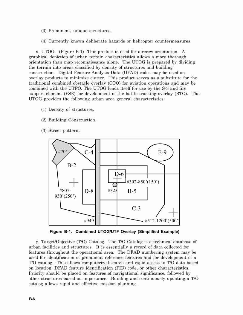
B-6
(3) Prominent, unique structures,
(4) Currently known deliberate hazards or helicopter countermeasures.
x. UTOG. (Figure B-1) This product is used for aircrew orientation. Agraphical depiction of urban terrain characteristics allows a more thoroughorientation than map reconnaissance alone. The UTOG is prepared by dividingthe terrain into areas classified by density of structures and buildingconstruction. Digital Feature Analysis Data (DFAD) codes may be used onoverlay products to minimize clutter. This product serves as a substitute for thetraditional combined obstacle overlay (COO) for aviation operations and may becombined with the UTFO. The UTOG lends itself for use by the S-3 and firesupport element (FSE) for development of the battle tracking overlay (BTO). TheUTOG provides the following urban area general characteristics:
(1) Density of structures,
(2) Building Construction,
(3) Street pattern.
Figure B-1. Combined UTOG/UTF Overlay (Simplified Example)
y. Target/Objective (T/O) Catalog. The T/O Catalog is a technical database ofurban facilities and structures. It is essentially a record of data collected forfeatures throughout the operational area. The DFAD numbering system may beused for identification of prominent reference features and for development of aT/O catalog. This allows computerized search and rapid access to T/O data basedon location, DFAD feature identification (FID) code, or other characteristics.Priority should be placed on features of navigational significance, followed byother structures based on importance. Building and continuously updating a T/Ocatalog allows rapid and effective mission planning.
B-2
D-8
C-3
E-9
B-5
D-6
C-4 #701
#512-1200’(500’)
#302-850’(150’)
#949
#807- 950’(250’)
#323
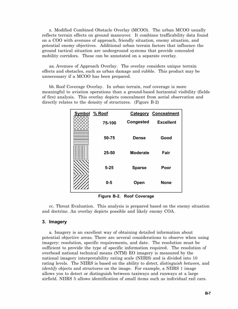
B-7
z. Modified Combined Obstacle Overlay (MCOO). The urban MCOO usuallyreflects terrain effects on ground maneuver. It combines trafficability data foundon a COO with avenues of approach, friendly situation, enemy situation, andpotential enemy objectives. Additional urban terrain factors that influence theground tactical situation are underground systems that provide concealedmobility corridors. These can be annotated on a separate overlay.
aa. Avenues of Approach Overlay. The overlay considers unique terraineffects and obstacles, such as urban damage and rubble. This product may beunnecessary if a MCOO has been prepared.
bb. Roof Coverage Overlay. In urban terrain, roof coverage is moremeaningful to aviation operations than a ground-based horizontal visibility (fieldsof fire) analysis. This overlay depicts concealment from aerial observation anddirectly relates to the density of structures. (Figure B-2)
Figure B-2. Roof Coverage
cc. Threat Evaluation. This analysis is prepared based on the enemy situationand doctrine. An overlay depicts possible and likely enemy COA.
3. Imagery
a. Imagery is an excellent way of obtaining detailed information aboutpotential objective areas. There are several considerations to observe when usingimagery: resolution, specific requirements, and date. The resolution must besufficient to provide the type of specific information required. The resolution ofoverhead national technical means (NTM) EO imagery is measured by thenational imagery interpretability rating scale (NIIRS) and is divided into 10rating levels. The NIIRS is based on the ability to detect, distinguish between, andidentify objects and structures on the image. For example, a NIIRS 1 imageallows you to detect or distinguish between taxiways and runways at a largeairfield. NIIRS 5 allows identification of small items such as individual rail cars.
Symbol % Roof Category Concealment
75-100
50-75
25-50
0-5
5-25
Congested
Dense
Moderate
Open
Sparse
Excellent
Good
Fair
None
Poor
B-8
An NIIRS 6 image can identify automobiles as sedans or station wagons. A NIIRS9 product should detect individual spikes holding railroad track. As a generalrule, NIIRS 5 to 7 images are of sufficient resolution to provide staffs andaircrews sufficient detail needed for planning operations. For SOF or SARmissions, imagery with greater resolution may be required.
b. Requests for current, high-resolution imagery may require a significanttime to fulfill. Avoid over-tapping limited resources and assets by asking only forwhat you need. Consult the NIIRS manual or your intelligence unit for moreinformation about imagery products.
c. Specify information requirements precisely. If you are executing a pre-planned SAR mission or expect to ingress/egress a city from a certain direction ata specific time, request imagery that closely resembles that profile. The lead-time for obtaining imagery to meet specific requirements are based onprioritization of needs and may entail a time lag between the time of the requestto dissemination of the product. The characteristics of various imagingtechniques and the peculiarities of various imaging platforms should bethoroughly understood to maximize the use of the information. For example,imagery taken at an oblique angle versus straight overhead aids in determiningheights of building and obstacles. It also helps highlight utility poles. Earlycoordination with intelligence sections assists in obtaining data from national,theater, and tactical assets.
d. There are vast amounts of archived imagery available. If older imagerymeets operational requirements, it may be more quickly obtained than newlygenerated requests for imagery. It is important to carefully evaluate the risks ofusing dated information. For example, in Operation RESTORE DEMOCRACY, aunit planned flight routes in Port-au-Prince using overhead imagery. The ingressroute followed a canal, and the aircrew plan to use identifiable bridges asnavigation aids to find a specific street. Unfortunately, the photos were over ayear old and depicted three bridges over the canal. The unit discovered one ofthe bridges was no longer there. This caused momentary confusion overcome byreference to other terrain features based on their imagery study.
e. In addition to image resolution and currency of the information, there is avariety of imagery products available. These include three-dimensional imageryof the T/O area, obtainable in different scales, that is useful for determining theheight relationship of buildings in the objective area. Large wall-sized imagerysheets are available and can be used for planning, briefing, intelligence updates,and updating hazards. Whenever possible, compare the most current imageryavailable to map products to ensure the most current and accurate data are usedfor mission planning and execution.
C-1
Appendix C
MUNITIONS
1. Laser-Guided Bomb
a. LGBs offer accurate targeting using laser terminal guidance. Variousweapons yields are available based on Mark 82, 83, or 84 series weapons.Paveway II guidance kits attached to the appropriate series weapons make up theguided bomb unit (GBU). Urban LGB considerations include building proximity,laser LOS, podium effects due to building faces, collateral damage due to weaponyield, guidance failure, smoke, haze, and rubble.
b. Planners should use the JMEM to determine weapons effects associatedwith the appropriate GBU. In general LGBs provide good capability against softtargets due to the associated blast, fragmentation, and overpressure. Penetrationcapability is enhanced with delayed fusing and increased impact angles. UseBomb Live Unit (BLU) 109 bomb bodies against hard targets when desiring deepweapon penetration. Weapons impact angles are generally determined based onhorizontal targets. The weapon impact angle against vertical targets can beestimated by adding approximately 90 degrees to the horizontal impact angle.
c. Laser spot placement should be considered due to the tendency for GBUweapons to impact short of a target. Laser designators should elevate the laserspot relative to the desired impact point to offset inherent trajectory sagassociated with LGBs. Elevating the laser spot allows the GBU to maintain ahigher potential energy level into the terminal phase of the flight at which timethe spot can be shifted down and onto the desired impact point.
2. Maverick (AGM-65 Block B/D/E/G/K)
a. AGM-65 Maverick provides a launch and leave precision guided munitionscapability in urban terrain operations. AGM-65 A/B models are centroid trackingEO versions which utilize a shaped charge warhead and are capable againstsmall, point targets such as vehicles, including armor. AGM-65 D is similar,except it uses IR imaging to track targets. Larger targets may be engaged usingthe AGM-65 G, or an IR Maverick with a HE warhead. The G model Maverickhas a forced correlation capability. This allows selection of a specific desiredmean point of impact (DMPI) on larger targets as well as a ground selectablefuzing delay allowing the missile to penetrate the outer surface of the target anddetonate inside. AGM-65K utilizes an EO seeker, carries the same blast warheadas the AGM-65G, and provides significantly greater standoff range than the AGM-65B. It also has forced correlation track capability. Time of flight of the missileshould be considered when employing the AGM-65 against moving vehicle targetsin urban terrain since terrain masking due to vertical obstructions will cause themissile to break lock. Once the missile breaks lock, its flight path will becomeunpredictable, but it remains armed and will detonate upon impact.Consideration should be given to releasing at closer slant ranges if friendly forcesare in close proximity to the target to minimize the missile time of flight. When
C-2
using the AGM-65 G in the force correlation mode, consideration should be givento the apparent target size when engaging targets in close proximity to friendlypositions. A decrease in slant range will provide a larger apparent target, whichin turn will allow a more precise aimpoint to be selected.
b. For the AGM-65F IR Maverick, breaklock algorithms will cause the missileto go into a correlate track or “stare” mode. In this mode, the weapon willattempt to track any object closest to the centroid of the IR scene at breaklock. Ifthis occurs, there is no guarantee that it is the intended target. If no other objectis present, the missile will drive to the centroid of the IR scene and detonate.The hit will be entirely dependent on the composition of the missile’s IR scene.The point of impact relative to the intended target can only be a guess.
c. Regarding the AGM-65E Laser Maverick, if the proper laser source is lostfor over 1.5 seconds the missile will safe itself and assume a lofted profile. Theintent is for the missile to land long as a dud. This feature, in addition to themodest yield and excellent penetration characteristics make it a potentialweapon for urban CAS.
3. Cluster Munitions
a. Generally, cluster munitions are appropriate for use in the urbanenvironment only in very limited circumstances. The area effects of the weaponand relatively high dud rate of the submunitions often make them inappropriatefor use in densely populated areas because of their great potential for immediateand persistent civilian collateral damage. If specific circumstances suggest theuse of cluster munitions, very careful consideration should be given to thecollateral damage likely to result. Particularly after air operations in Kosovo, theuse of air delivered cluster munitions has become a very sensitive one in theinternational community. Expect that approval authority for the use of clustermunitions will be retained at higher levels in future operations.
b. Cluster Bomb Units (CBU) include mark (Mk) -20 Rockeye, CBU-87combined effects munition (CEM), CBU-89 Gator air delivered mines, and CBU-97 sensor-fuzed weapon (SFW). Each weapon uses a dispenser. Rockeye uses ashaped charge penetrator and is typically used against armor. CEM bombletshave three kill mechanisms, shaped-charge penetration, fragmentation, andincendiary. The Gator consists of anti-armor and antipersonnel mines. SFWsconsists of submunitions designed for use against tanks, armored vehicles,artillery, armored personnel carriers (APC), and support vehicles.
c. Cluster weapons can be equipped with either a mechanical time fuze orradar proximity fuze. The type of fuze will dictate the type of delivery option/mode to use.
(1) While very reliable, time fuzes do not allow a great deal of flexibility indelivery options. Once the arming time is selected prior to flight, it cannot bechanged. When unsure whether a low-altitude or medium-altitude employment
C-3
option will be used during the mission, set the primary time for a medium-altitude option and the option time for a low-altitude option.
(2) Proximity fuzes provide greater flexibility for delivery of the clusterweapon. Variations in munitions time of fall will not affect the fuze functionaltitude as long as fuze-arming restrictions are met. Delivery parameters can beadjusted for the situation.
d. Advantages of CBU over general-purpose bombs include:
(1) good area coverage,
(2) very effective against personnel and soft-skinned vehicles ,
(3) ability to penetrate armor,
(4) low-altitude deliveries.
e. CBU-89 provides a minefield for a controlled period and is excellent for adenial/channelization
f. Disadvantages of CBU include:
(1) fixed employment slant ranges for timed fuzes,
(2) high drag,
(3) dud bomblets,
(4) time-delay bomblets may hinder friendly passage through an area,
(5) pattern size and coverage make delivery in a troops in contact (TIC)situation difficult, if not impossible.
4. Joint Direct Attack Munition (JDAM) (GBU-29, GBU-30, GBU-31, GBU-32)
a. The JDAM can be used for CAS, interdiction, SEAD, naval anti-surfacewarfare, and amphibious strike missions. This munition serves to upgrade theexisting inventory of Mk 80 series general-purpose bombs. This is accomplishedby integrating it with an INS/GPS guidance kit. JDAM variants for the Mk-81250-pound and Mk-82 500-pound bombs are designated GBU-29 and GBU-30,respectively. The Mk-83 1,000-pound, and Mk-84 2,000-pound general-purposebombs, are designated as the GBU-31 and GBU-32. Hard Target penetrators thatare being changed into low-cost JDAM include the 2,000-pound BLU-109 and1,000-pound BLU-110.
b. The JDAM can be continuously updated by aircraft avionics systems beforerelease. Once released, the INS/GPS of the bomb will take over and guide thebomb to its target regardless of weather. Guidance is accomplished via the tight
C-4
coupling of an accurate GPS with a 3-axis INS. The guidance control unitprovides accurate guidance in both GPS-aided INS modes of operation and INS-only modes of operation. This inherent JDAM capability will counter the threatfrom near-term technological advances in GPS jamming. The weapon systemallows launch from very low to very high altitude. It can also be launched in adive, toss, loft, or in straight and level flight with an on-axis or off-axis delivery.JDAM also allows multiple target engagements on a single pass delivery. JDAMprovides the user with a variety of targeting schemes, such as preplanned and in-flight captive carriage retargeting.
5. Tube launched, Optically tracked, Wire guided (TOW)
a. The TOW is a precision guided munition (PGM) with a small CEP. Theminimum engagement range is 500 meters. An external guidance mechanism(laser) is not required. The warhead is able to penetrate urban structures as wellas conventional armor.
b. The following discussion concerning the “Hellfire” covers PGM and shapedcharge characteristics in detail, however the TOW delivery mechanics arementioned here as the guidance mechanisms differ. When using TOW in anurban environment, building types will have to be analyzed to determine windowlocations, type construction (framed or frameless), etc. Generally, framedbuildings are newer and use steel girder construction; Therefore, it will be harderto achieve the desired effects with a shaped charge warhead than when usedagainst frameless building, which tends to be an older masonry structure. Thestructure construction will determine whether the building’s room is destroyed,the building collapses, or the target is unharmed. Generally, TOW missiles arenot fired into an open window or aperture because the PGM warhead will travelthrough the room and impact the other side of the room and far wall. This willnegate the warhead effects since the warhead will detonate and explode into thewrong room. Depending on the building, target, and desired effects, TOWs maybe aimed at windows, the upper, middle, or lower one-third part of a buildingside, or into the roof.
6. Hellfire
a. Shaped charged warheads are not optimized against urban structures.TOW or Hellfire can destroy small buildings constructed of light wood, metal, orconcrete. TOW or Hellfire shaped charge penetration of generic (brick, concrete,or wood) building structures will generally be limited to one compartment of thebuilding due to shaped charge size, shaped charge impact characteristics, andaverage missile velocity. As a rule of thumb, Hellfire shaped charge jetpenetration is 42 inches of rolled homogenous armor (RHA), 10.5 feet of non-reinforced concrete, 12 feet of wood, and 12.5 feet of unconfined sand. In general,expect a TOW warhead to blow an 8-18 inch hole in 8 inches of double reinforcedconcrete and a 5-12 inch hole in triple brick. Firing a TOW into cinder blockblows a 3-5 foot hole, or roughly large enough for a man to crawl through. Thesize is not only dependent on the material, but also on the angle of attack upon
C-5
impact. A higher angle of impact against a vertical surface increases the neteffective thickness of the wall that the warhead must travel through (similar tosloped armor). Expect the missile body, motor, and casing to travel into the room,adding to the spalling effect. With more porous materials (concrete), the spallingfragments are larger, but they lose energy quicker and do not travel as far intothe room. The resulting cloud of masonry dust is an ineffective kill mechanism,but has the equivalent effect of throwing sand into someone’s eyes. The dustcloud covers an approximately ten foot square area. Against masonry structures,masonry dust will affect personnel inside the room and dust will be visiblecoming from the impact hole.
b. Shaped charge warheads can penetrate the above materials. Localizedspalling normally spreads out from the entry point in an approximate 6-inch to 1-foot spall cone. The warhead effect immediately starts to breakup inside thebuilding, but due to its speed, may travel some distance before stopping. Whenimpacting an outer wall (reinforced concrete or triple brick), most of theoverpressure is dissipated outside of the building upon impact. The followingpeak overpressure effects are achievable with the Hellfire shaped chargewarhead: 3 pounds per square inch (psi) at 60 feet, 6 psi at @ 40 feet, and 12 psi at25 feet. A rule of thumb for comparing any warhead penetration against 6500 psiconcrete is: steel thickness divided by .556 equals the equivalent 6500 psiconcrete penetration. Example: 2 inches of steel/.556 = 3.6 inches of concreteequivalent. Therefore, knowing what a warhead can penetrate in terms of steelallows a conservative estimate of concrete penetration. It is important to note,though, that concrete density and building materials vary across the world.Shaped charged warheads will still penetrate any building material, but theinternal effect may be lessened. The overpressure falls off quickly and isequivalent to the cube of the radius from the impact. For comparison - if anominal warhead could produce lethal effects against personnel at 2 feet, then at8 feet the effects would render personnel unconscious, and at 512 feet, the effectswould be heard, but not felt. The incidental overpressure effects are of a veryshort duration (<30 milliseconds) and may not cause immediate incapacitation,but require several minutes before internal bodily effects are felt on such organsas the kidney, liver, spleen, eardrums, etc. If the material is thin, the missile willpass through the material and expend most of its overpressure inside thebuilding upon impact with the interior wall/floor. Only 1 inch plywood, orequivalent, is required to detonate the Hellfire warhead. If the warhead is shotthrough an aperture (ex. window glass, doorway, etc.), the resulting overpressurewill be much greater inside the building or room. However, the incapacitativespalling is lessened because the warhead travels through the room and impactson the back wall of the room. At short distances (room width) the spalling conehas not had time to expand, therefore only enemy personnel directly within thespall cone will be injured by the spall. However, total kill mechanisms includeheat, flash blindness, eardrum rupture, concussion, and fragments. Shapedcharged warheads are not optimized against urban structures, however, shootinga missile into a building or room should immobilize the enemy, if not kill him. Amoderate Pi (fragmentary effects only) is achievable with a TOW or Hellfire usedagainst double reinforced concrete or triple brick.
C-6
c. Against a 10-inch thick, non-reinforced concrete structure, Hellfirenormally produces a clear hole approximately 3 feet in diameter. Two missilesfired in rapid or ripple can be very effective against reinforced concretestructures. The first missile clears an approximate 3 foot opening that fills withsmoke for several seconds. The second missile is guided through the openingcreating significantly greater overpressure inside. Any remaining reinforcementbars should cause the second missile to detonate on the wall, reducing the effect,although overpressure inside the enclosure rises markedly at detonation becauseof the large opening. Highly volatile materials inside the enclosure may producetoo much smoke from the first missile, creating a tracking hazard for the secondmissile and affecting accuracy.
d. Actual measured data in a bunker indicates that the spall shower can be avery effective secondary weapon given a masonry or armored steel target. In atest firing, the warhead detonated 4 feet in front of the bunker in earth terrainbefore penetrating 30 inches of reinforced concrete bunker wall. Overpressureand concrete spall destroyed two anthropomorphic dummies inside the bunker.The spall shower had a weight of 128 pounds and lethal concrete fragments wererecovered from witness panels at a density of over 12 fragments per square footon the back of the 20 square foot bunker. The jet passed through the 12 inchreinforced concrete rear wall and greater than 3 feet into the surrounding earthembankment. Typical brick or masonry structures will react similar to thebunker but thinner walls will produce proportionally smaller spall showers.
e. The tandem warhead is not expected to make any difference in the effect onoccupants inside the building relative to a single high explosive anti-tank (HEAT)warhead, regardless of whether the warhead detonates inside or outside. DuringOperation Just Cause in Panama, one missile was fired into each floor of aheadquarters building. Although the missiles detonated upon contact with thewindows, internal blast overpressure gutted an entire floor overturning furnitureand file cabinets and igniting combustibles.
f. The amount of overpressure inside confined spaces depends upon theinternal volume of the enclosure. It is also modified by the volume of solids in theenclosure, such as furniture, file cabinets, and personnel.
g. The Hellfire is not a quick reaction CAS weapon. To employ Hellfire in anurban environment requires careful consideration of LOS geometry. Hellfireprovides standoff capability versus enemy air defense at the expense ofincreasing altitude to obtain LOS. If using autonomous designating, a balancebetween designator LOS and exposure to the enemy weapons engagement zone(WEZ) is required. The Hellfire trajectory is optimized for an up and over, top-down attack profile in order to defeat enemy tanks. The trajectory ranges from10 to 25 degrees downward at impact. This trajectory can not be changed to fly adirect profile such as the TOW flies. However, this profile is useful in engagingtargets in buildings or in streets between buildings. To shape the terminaltrajectory to the flattest profile requires understanding the effects of launchmode, range to target, and delay designation. Generally, a flatter profile will beflown at minimum launch ranges, while longer ranges increase the terminal dive
C-7
angle. Regardless of range or delay, the AGM-114K flies a steeper profile than theAGM-114B. The most significant limitation of PGMs is their minimum armingdistance.
7. 20mm Cannon
a. The M56 round will not penetrate heavy armor at tactical ranges. Itspenetration on concrete ranges from minimal to none. Precision guidance unit(PGU) rounds will penetrate cinderblock walls and have a reasonable capabilityversus concrete. On RHA, it penetrates 3/8 inch at 45-degree obliquity at 2500feet slant range from a 450 knot aircraft. This is approximately equivalent to ½inch at normal (perpendicular) impact. Vertical surfaces should not dud the M50series round. High explosive incendiary (HEI) round impacts have the smallestfragmentation pattern and will minimize ricochets, thus minimizing collateraldamage. HEI rounds are a potential fire starter when used against woodenstructures. Target-practice 20mm rounds ricochet more than HEI rounds. InertPGU-27 20mm, delivered 7.5 degrees downward, will ricochet as far as themaximum range of the round (2000 meters) and up to 400 feet from the point ofimpact when delivered against horizontal hard flat surfaces. This ricochet effectmay affect noncombatants. HEI rounds (M56A3/A4) can produce casualties toexposed personnel within a +/- 2 meter radius.
b. Tracers are a double-edged weapon in this environment. The normalmethod of firing 20mm is to shoot, observe the rounds impact, and if necessary,walk the rounds onto the target. However, in urban areas, rounds off target aremore likely to cause collateral damage. In Chechnya, the Russians prohibitedtracers on any firing platform due to the intense and devastating fire returnedfrom the Chechen rebels. A compromise solution is to mix tracer and non-tracerrounds in a 1:10 mix. Given the M197 rate of fire (650 rounds per minute), atracer would be seen once for every 10 rounds fired. The reverse is true if theenemy is firing at you with tracer-mixed ammo (i.e., for every tracer seen, 10-20rounds are never seen). If tracers are not used, 20mm HEI detonations againsthard surfaces cue the pilots where the rounds are impacting.
8. 25mm Cannon
a. Both the AC-130U gunship and the AV-8B Harrier use the GAU-12/U 25mmgattling gun.
b. The 25mm cannon is effective against personnel and soft-skinned vehiclesin the open or under light cover. It has a maximum capacity of 3,000 rounds and arate of fire of 1,800 rounds per minute. Burst length is computer adjustable from15 to 350 rounds. The 25mm cannon is an effective area suppression weapon.Available munitions are HEI, API, and training projectile (TP).
9. 30mm Cannon
a. The M230A1 “Chaingun” is used by the Apache helicopter against soft-skinned and lightly armored targets, and for self-defense. It has a single barrel,
C-8
externally powered hydraulically driven turret. Maximum capacity is 1200rounds with a rate of fire of 600-650 rounds per minute. Maximum range is 4,000meters with a maximum effective range of 1500 to 1700 meters. Ordinanceincludes the M789 HE dual-purpose ammunition.
b. The GAU-8 30mm cannon is a seven-barrel; percussion primed Gatling gunused by the A-10. It is effective against tanks, armored vehicles, and a variety ofmobile and fixed targets. The GAU-8 holds 1,150 rounds and uses three differentbullets; TP, HEI, and an armor piercing (AP) depleted uranium round. The APpenetrates armor at slant ranges out to 6,000 feet from a low altitude, less than15-degree delivery angle and outside 10,000 foot slant range from high diveangles. The HEI round functions at ranges beyond the computed gun sightmaximum slant ranges. The TP round is used for training, but possesses a limitedpenetration capability. The computed gun sight allows accurate employment upto 15,000 foot slant range. The velocity of the GAU-8 bullet 6,000 feet from themuzzle is the same as a 20mm bullet velocity at the muzzle. The high bulletvelocity, rate of fire (approximately 70 rounds per second), and small dispersion(5-mile radius for all bullets) provide a good bullet density and a powerful punch.The GAU-8 is a very reliable, accurate, and simple point-and-shoot weapon thatcan be used close to friendly ground troops and possesses a relatively long-rangecapability. Disadvantages include a large ricochet pattern, decreased bulletdensity at shallow dive angles, and long slant ranges.
10. 40mm Cannon
a. The AC-130 Gunship employs the M2A1 Modified 40mm cannon, which firesvarious types of HE and WP rounds. The 40mm cannon is an effective weapon forurban terrain, especially urban CAS. This weapon is a good compromise betweenlethality, collateral damage, and fratricide potential. Most 40mm munitions havelimited penetration capability. Thus, a significant factor limiting 40mmeffectiveness is the abundance of cover for targets in urban terrain. The gun firesa high explosive-plugged (HE-P), high explosive incendiary-plugged (HEI-P), HEIzirconium, and armor piercing tracer (APT) rounds.
b. The HE-P cartridge is used against material and personnel targets. Theround utilizes the Mk-27 fuze which functions on light impact. Fuze action time isshort, giving the ammunition limited penetration capability. This round is fairagainst hard targets, but does provide suppression for personnel in the open orunder light cover.
c. The HEI-P cartridge is used against material targets. It was developedspecifically to increase fire-starting capability against trucks. The round hasgood incendiary potential but contains less trinitrotoluene (TNT), producing lessfragmentation than HE-P. The standard Mk-2 projectile body was modified byadding a metal liner, producing bright sparks on detonation. This effect makesthe round a good choice for target marking. In particular, when the gunshipcannot maintain constant LOS with the target, a well boresighted system canmark a target even if it cannot observe round impact. Because of the fire-startingpotential of this round, carefully consider using it during urban operations.
C-9
d. The HEI zirconium cartridge is used against material and personneltargets. It was developed specifically to increase fire-starting capability, whilemaintaining adequate fragmentation for anti-personnel use. The standard Mk-2projectile body was completely redesigned by adding additional explosive fill anda zirconium liner, producing bright sparks on impact. Because of the fire-startingpotential of this round, carefully consider using it during urban operations.
e. APT rounds penetrate RHA of various thicknesses. The projectile containsno explosives, relying on kinetic energy as its damage mechanism. APT can beused in urban operations to minimize collateral damage. It is generallyineffective against multiple personnel targets and difficult to see the actualimpact point of the round.
11. 105mm Cannon
a. The AC-130 Gunship carries an M102 105mm Cannon. This gun fires the105mm HE rounds.
b. The M102 105mm HE cartridge is used against such targets as personnel,material, and light to medium structures. It has a large lethal fan from shrapneland blast. Upon detonation, this projectile produces approximately 3,000fragments. As urban terrain often requires target engagement very near friendlypositions, use M102 HE only if adequate cover is available and the target cannotbe attacked other means. For other than general-purpose applications, the M102round can accommodate various fuzes. The M-557 fuze is good for general-purpose point detonation or selectable delayed detonation. It requires aminimum of one inch of wood to function reliably. The M102 performs poorlyagainst hard targets or buildings with thick concrete, brick, or rock walls, unlessspecifically fuzed for this application. The fused munition unit (FMU)-151/Bhardened fuze gives the M102 capability against hard targets in the delay mode.It requires a minimum of two inches of wood to reliably function. The M102 withthis fuze will penetrate 10 inches of 5,000 psi reinforced concrete (0 degreesobliquity). When fired against typical structures, the point detonating (PD)function opens holes about three feet in diameter and the delay function resultsin penetration of exterior walls with detonation immediately inside the wall. Foranti-personnel applications, the M-732 fuze detonates the projectile at about 7meters above the ground. Large buildings in urban terrain may cause the fuze tofunction early, reducing effectiveness, and increasing collateral damage. The fuzewill also point detonate if needed or if the proximity function fails.
12. Rockets
a. 2.75 inch rockets can be used against various urban targets including, lightwood frame buildings, personnel, and area targets. The rocket produces asignificant psychological impact. Unguided rockets have an inherent dispersionerror. Add to this error an aiming error, rocket pod boresight error, and rangeestimation error, and the results are a larger target dispersion error. Laserrangefinders, launcher stabilization adapters, and firing at close range

C-10
compensate for some of this dispersion error. Fuze arming may be a factor forshort firing range. Mk-423 PD and the Mk-427 PD fuzes arm at 300 feet and 1250feet respectively. A rule of thumb for the 2.75 inch Mk-151 warhead penetrationagainst 6500 psi concrete is 4 to 6 inches. In addition, smoke, flechette, andvisible/IR illumination rounds are available.
b. The 5 inch rocket may be used for dense structures. The Mk-24 Mod 0,M191 warhead and fuze combination penetrates 24 inches of reinforced concreteand becomes armed at 800 feet. However, due to weight restrictions, fewer 5 inchrockets can be carried if a mix of ordnance is desired. The large blast effect,equivalent to 105mm artillery rounds, may not be desired near personnel. Forcomparison, the Mk-24 general purpose (GP) 5 inch rocket carries approximately4 times the warhead weight as the 2.75 inch, 1.5 times a TOW, and .7 times theweight of a Hellfire warhead. The 5 inch rocket has similar dispersion error asthe 2.75 inch rockets.
13. Medium/heavy Machine-guns (7.62mm and .50 caliber)
a. Machine-guns. The .50-caliber machine-gun and the 7.62-mm M60, M240,and M-134 machine-guns provide high-volume, long-range, automatic fires forsuppressing or destroying targets. They can be used to penetrate lightstructures. The 50-caliber machine-gun is most effective in this role. Tracersfrom all machine-guns are likely to start fires, but the .50-caliber tracer is moreapt to do so.
b. Employment. The primary consideration is the limited availability of long-range fields of fire. Although machine-guns should be employed at the lowestlevel possible, grazing fire at ground level is often obstructed by rubble. Becauseof their reduced penetration power, 7.62mm machine-guns are less effectiveagainst masonry targets than the .50-caliber. However, their availability andlight weight make them well suited to augment heavy machine-guns or in areaswhere .50-caliber machine-guns cannot be positioned or are not available.
c. Penetration. The range and type of target affects the penetration ability ofthe 7.62-mm and .50-caliber rounds. At 200 meters, the 7.62-mm ball roundpenetrates a single layer of sandbags, but not a double layer. The armor-piercinground does only slightly better. Concentrated machine-gun fire penetrates typicalwall construction. It will not normally penetrate reinforced concrete structuresor dense natural stone walls. Internal walls, partitions, plaster, floors, ceilings,common office furniture, home appliances, and bedding are easily penetrated byboth 7.62-mm and .50-caliber rounds. Table C-1 details the penetrationcharacteristics of the 7.62mm ball round.

C-11
Table C-1. Penetration Capabilities of 7.62mm (Ball) Round
d. The .50-caliber round penetrates better at all ranges. For hard targets,obliquity and range affect .50-caliber penetration. Both armor piercing and ballammunition penetrate 14 inches of sand or 28 inches of packed earth at 200meters, if the rounds impact perpendicular to the flat face of the target. Table C-2 explains the effect of a 25-degree obliquity on a .50-caliber penetration.
Table C-2. Rounds (Rds) Needed to Penetrate Reinforced Concrete Wall(At a 25-Degree Obliquity)
e. Protection. Barriers against small arms are also effective against 7.62-mmrounds with some exceptions. The 7.62-mm round penetrates a windowpane at a45-degree obliquity, a hollow cinder block, and both sides of a car body. It alsopenetrates wooden frame buildings. The .50-caliber round penetrates all commonurban materials except a sand-filled 55-gallon drum.
Range (m) Pine Boards (in) Cinder Block (in) Concrete (in) Dry Sand (in)25 13 8 2 5100 18 10 2 4.5200 41 8 2 7
Thickness (ft) 100 m 200 m2 300 Rds 1,200 Rds3 450 Rds 1,800 Rds4 600 Rds 2,400 Rds

D-1
Appendix D
PERSONNEL RECOVERY
1. Personnel Recovery
a. PR is an umbrella term for operations focusing on the task of recoveringcaptured, missing, or isolated personnel from danger. It includes, but is notlimited to, theater SAR; CSAR; SERE; evasion and recovery (E&R); and thecoordination of negotiated as well as forcible recovery options.
b. Urban PR. All military personnel, including aviators, have the potential tobecome isolated. Recovery in an urban setting poses a unique challenge and canplace a heavy demand on the isolated person(s), the recovery force, andoperational planners tasked to return this individual to friendly control.Successful recovery of the isolated person, specifically the E&R component, maybe predicated on overcoming a number of problems unique to an urbanenvironment. With a higher indigenous population, the risk of immediate capturewill be proportionally higher. It is also very likely that an evader in an urbansetting will draw attention and thus be quickly cut off from friendly support.Therefore, individuals who can avoid immediate capture must be thoroughlyfamiliar with urban evasion techniques. This is particularly important foraviators who, although trained in traditional evasion procedures (nonurbansettings), are confronted with an unfamiliar environment. The challenges ofurban evasion are mitigated through realistic training and a prepared evader.Training and preparation are also essential to a successful PR mission. Othercritical elements include an effective C2 architecture and recovery force. Acomprehensive understanding of urban evasion and recovery procedures isnecessary because all elements of a joint force can be tasked to lend assistance inan urban PR mission.
c. Additional information is found in the following manuals; JP 3-50.2,Doctrine for Joint Combat Search and Rescue; JP 3-50.21, JTTP for CombatSearch and Rescue, JP 3-50.3, Joint Doctrine for Evasion and Recovery; Air ForceDoctrine Document (AFDD) 2-1.6, for CSAR, or AFTTP 3-1, Volumes 1, 3, 24, and25 (Classified).
2. Evasion
a. Evasion skills. Urban evaders must be familiar with and skilled inmovement and concealment techniques. The ability to use buildings, rubble,foliage, smoke, shadows, and sub-surface avenues will conceal movement and helpavoid detection. Movement during the hours of darkness or low light conditionswill also help minimize detection. Urban environments offer numerous areas tohide. Basements, subway tunnels, sewers, and other underground structures canoffer suitable hideouts. Security during evasion movement may be enhanced bythe use of specialized equipment, such as NVDs. These devices are also usefulwhile conducting surveillance before attempting to move to a safer area and/orsuitable recovery site.
D-2
b. Evader Movement. The absence of a nearby, suitable recovery site (e.g.,HLZ) and/or the presence of hostile forces may require evader movement over asignificant distance in order to link-up with friendly forces. Therefore, evadersmust be able to precisely navigate and report their location. In an urbanenvironment, traditional navigation skills may be degraded. Man-madestructures will affect the evader’s ability to take a straight route, visually acquireprominent landmarks, or view celestial navigational cues. Commercial hand-heldGPS receivers provide specific position/location; however, their accuracy canyield position errors up to 150 meters, a margin that could equate to several citystreets or blocks. An adequate GPS position may not be attainable in an urbanenvironment due to satellite obscuration. Urban evaders will have to rely onmajor urban features including significant buildings, street names, and majorintersections to provide specific location to recovery forces.
3. Charts, Communications, and Signaling
a. Charts, imagery, and landmarks. Standard 1:250,000 scale Evasion Charts(EVCs) may not provide sufficient detail to allow urban land or aerial navigation,especially in city centers. As such, providing aviators and recovery personnelwith larger scale special purpose urban or high-resolution imagery are a priorityconsideration. Such charts and imagery can be difficult to obtain, but can greatlyassist the mission planners in pinpointing the location of the evader before andduring the recovery effort. During pre-mission study of urban environments,mission planners should identify significant (easily recognizable) landmarks andterrain features to serve as navigational reference points and as a means todetermine location. Examples may include bridges, high-rise buildings,cathedrals, stadiums, major road intersections, or natural high ground (hilltops).Designate one selected feature or geoposition as the search and rescue dot(SARDOT). The SARDOT serves as a predesignated position from which evadersand recovery forces reference their current location. The evaders’ position istransmitted relative in terms of radial/distance from the SARDOT. The (ATO)Special Instructions (SPINS) will include SARDOT location and specificinstructions on how to use the SARDOT.
b. Communications. Communication presents another challenge for evaders.Currently fielded survival radios such as the PRC-90 and PRC-112 are non-secureand LOS limited. Urban terrain may block radio signals. In addition, radiotransmissions can be intercepted and exploited by opposition forces. They mayglean important information or find an evader’s location using DF equipment andtactics. Although available in limited quantity (1000 units), the newly fieldedPRC-112B (also called the HOOK 112) survival radio is a conventional PRC-112modified with a GPS receiver. It is also upgraded with an encoded data burstcapability that provides a covert or semi-secure means to communicate. (NOTE:Voice transmission over any of the five HOOK 112 frequencies is not secure. Onlythe data burst feature can be encoded for semi-secure communication.)Preprogrammed or free-text messages can be data burst transmitted andreceived. The PRC-112B data burst feature communicates with rescue forcesthrough two specially designed airborne interrogation devices referred to as theSUITCASE Interrogator unit and QUICKDRAW unit. The QUICKDRAW, fielded
D-3
only by the US Navy, is a less functional hand-held version of the SUITCASEInterrogator. The PRC-112B survival radio is affected by the same phenomenonand limitations of the standard issue PRC-90 and PRC-112 radios, including thoseassociated with LOS and DF exploitation. Should the survival radio becomeunusable or inoperable, consider using existing communications systems. Thecommercial telephone system, if working, is one possibility that should not beoverlooked. An international telephone credit card with emergency numbers aspart of the aviator’s personal evasion kit could simplify communicating viacommercial telephone. Another option is the use of cellular telephones, some ofwhich include secure capability as well as a worldwide coverage area. When allelectronic means of voice communications fail, evaders will need to use visualelectronic signals or construct a ground-to-air signal. These signals, that providea recognizable contrast with the urban background, can be manmade items issuedas survival equipment or improvised. Finally, Combat Survivor/Evader Locator(CSEL), if available, can provide two-way over-the-horizon secure message andvoice communications; near real time geopositioning information between theuser and a base station; and ability to identify/authenticate the specific user.
c. Signaling. Signaling methods should be pre-coordinated and documentedin the individual’s evasion plan of action (EPA). Furthermore, signaling devicesand their employment must be commensurate with the environment in whichthey are used, be rapidly discernible by rescue forces, and avoid compromisingthe evader’s location. To better facilitate the use of signaling devices, considerusing equipment that is compact enough to be carried, easy to operate, andreusable. An urban environment presents clutter and light pollution whenviewed from the air. Visually locating a lone evader in this situation can bedifficult. Employing covert signaling devices developed specifically for day/nightand vertical/horizontal application can overcome environmental limitations andallow the evader to become observable. The traditional signal mirror is visuallyobservable at considerable distances and can be directed toward specificobservers while concealed from unintended observers. However, careless use ofthis device can compromise an evader’s location. Although less observable,another option is the visual signal (VS) -17 panel (NOTE: currently not carried byUS Navy (USN) or USAF aviators). It is a brightly colored panel, which providesa bright color contrast when placed against a neutral background. A VS-17 panel,oriented vertically or horizontally, is generally easily recognized. Both the signalmirror and VS-17 panel should be used in accordance with the evasion plan ofaction to avoid unintended detection. Because the human eye can detect movingor blinking sources better than static or constant sources, careful considerationshould be taken in night urban signaling: Visible light lasers such as a “GreenBeam” work well. In addition, laser-pointing devices can be highly effective forsignaling to NVG equipped recovery forces. They can also be used to illuminate/designate targets or threats to the evader or recovery forces. (NOTE: In caseswhere laser-pointing devices are used, recovery package strike aircraft shoulduse caution when engaging a target designated by an evader. The evader may nothave the appropriate training/familiarity to perform target designation duties.)Another signaling device is the FIREFLY. Fireflies are IR light emitting diodes,powered by a 9-volt direct current (DC) battery. They are employed in twomethods, either in the factory setting mode or in a programmable mode. Each
D-4
mode dictates the sequence and frequency of the flash. The programmable modelhas a unique coding system, which allows any sequence of flashes up to fourseconds in duration, to be programmed into the unit. The advantage of theprogrammable model is the ability to code beacons with different flash rates,enabling any one to be distinguished from a group. Either model provides aneffective method of attracting attention of friendly forces. Equipped with severalFireflies, an evader can attach the lights to a length of string and display themfrom a window or rooftop for observation by recovery forces. Again, the bestemployment of this device will result from a comprehensive scheme outlined inthe individual’s EPA. Glint tape or other combat identification systems canfacilitate distinct identification of evaders. In addition, “No Power ThermalTarget Material” known as “cold sky” can enhance evader recognition to friendlyFLIR/IDS-equipped aircraft. Certain environments may permit the use of overtsignals such as smoke grenades, flares, penguns, and personal locator beacons(that emit homing signals) regardless of day/night conditions to assist recoveryoperations. However, employment of these devices must be measured against thepotential for unintended compromise of the evader’s position and added dangerto recovery forces.
4. Recovery
Urban recovery may increase the intelligence requirements for a successfulrecovery. Knowing the evader’s exact location is an essential element thatsignificantly reduces recovery force exposure time during the terminal phase of arecovery mission. Depending on threat assessments and vulnerabilities, timeavailable to search for the evader may be limited. Consider incorporating aconcept of operations to employ UAVs to locate an evader. Equipping evaderswith the latest technology in navigation and signaling devices improves theevader’s chances for swift and successful recovery. Evasion and recovery plansmust be carefully crafted, briefed and fully understood.
References-1
REFERENCES
Joint
1. Joint Pub 1-02, DOD Dictionary of Military and Associated Terms, As amendedthrough 10 January 2000.
2. Joint Pub 3-09.3, JTTP for Close Air Support (CAS), 1 December 1995.3. Joint Pub 3-50.21, JTTP for Combat Search and Rescue, 23 March 1998.4. Joint Pub 3-50.3, Joint Doctrine for Evasion and Recovery, 6 September 1996.5. Joint Pub 3-56.1, Command and Control for Joint Air Operations, 14 November
1994.
Multi-Service
1. The Air Land Sea Bulletin (ALSB) 96-1, article on “AC-130 Gunship CAS” writtenby Capt Havel, 18th Flight Test Squadron (FTS).
2. The ALSB 97-3, article on “AC-130 Employment during MOUT” written by CaptTaylor, HQ Air Force Special Operations Command (AFSOC/DOVF, Flight StandardsBranch).
Army
1. FM 90-10, Military Operations on Urbanized Terrain (MOUT), 15 August 1979.2. FM 90-10-1, An Infantryman’s Guide to Combat in Built-up Areas, 12 May 1993.3. FM 1-100, Army Aviation Operations, 21 Feb 1997.4. FM 1-111, Aviation Brigades, 27 Oct 1997.5. FM 1-112, Attack Helicopter Operations, 02 Apr 1997.6. FM 1-113, Utility and Cargo Helicopter Operations, 12 Sep 1997.7. FM 1-120, Army Air Traffic Services Contingency and Combat Zone Operations, 22
May 1995.8. FM 1-140, Helicopter Gunnery, 29 Mar 1996.9. FM 5-33, Terrain Analysis, 11 Jul 1990.10. FM 34-130, Intelligence Preparation of the Battlefield, 08 Jul 1994.11. FM 100-5, Operations, 14 Jun 1993.12. FM 100-103, Army Airspace Command and Control in a Combat Zone, 07 Oct 1987.13. FM 100-103-1, Integrated Combat Airspace Command and Control (ICAC2), 03 Oct
1994.14. TC 1-209, Aircrew Training Manual, Aviator/Aeroscout Observer, OH-58D, 09 Dec
1992.15. TC 1-211, Aircrew Training Manual, Utility Helicopter, UH-1, 09 Dec 1992.16. TC 1-212, Aircrew Training Manual, Utility Helicopter, UH-60/EH-60, 08 Mar
1996.17. TC 1-213, Aircrew Training Manual, Attack Helicopter, AH-1, 09 Dec 1992.18. TC 1-214, Aircrew Training Manual, Attack Helicopter, AH-64, 20 May 1992.19. TC 1-215, Aircrew Training Manual, Observation Helicopter, OH-58-A/C, 02 Mar
1993.20. TC 1-216, Aircrew Training Manual, Cargo Helicopter, CH-47, 08 Oct 1992.21. CALL Newsletter 90-9, Operation JUST CAUSE (Vols I, II, III).22. CALL Newsletter 93-7, Operations Other Than War Volume III, Civil Disturbance.23. CALL Lessons Learned Report, US Army Operations in Support of UNOSOM II.
References-2
24. CALL Bulletin 90-4, Introduction to Low Intensity Conflict.25. CALL Handbook 92-3, Fratricide Risk Assessment for Company Leadership.26. CALL Newsletter 92-4, Fratricide: Reducing Self-Inflicted Losses.27. CALL Newsletter 94-3, (Special Edition) Haiti.28. CALL Newsletter 93-1, (Special Edition) Somalia.29. CALL Newsletter 95-13, (Special Edition) Supporting the Peace: Bosnia-
Herzegovina.
Marine Corps
1. MCWP 3-35.3, Military Operations on Urbanized Terrain (MOUT), 16 April 1998.2. Aviation Combat Element Military Operations on Urban Terrain Manual, edition VI,
December 1997.
Navy
1. Naval Institute Proceedings, February 1998, “MOUT: The Show Stopper”written by Robert E. Polesny.
2. Navy Times Marine Corps Edition, February 16, 1998, “Urban Warriors”written by John R. Anderson.
3. Navy Aviation Systems Team Handbook AVDEP-HDBK-12, Mapping,Charting, and Geodesy.
Air Force
AFDD 1, Air Force Basic Doctrine, 1 Sep 1997.AFDD 2-1, Air Warfare, 22 Jan 2000.AFDD 2-1.3, Counterland, 27 Aug 1999.AFDD 2-1.6, Combat Search, and Rescue, 30 Sep 1998.AFDD 2-1.7, Airspace Control in the Combat Zone, 4 Jun 1998.AFDD 2-3, Military Operations Other Than War (MOOTW), 5 Oct 1996.AFDD 2-6, Air Mobility Operations, 13 Nov 1999.AFDD 2-6.1, Airlift Operations, 13 Nov 1999.AFDD 2-7, Special Operations, 1 Jul 1999.AFTTP 3-1, Series Publications.422 TES April 1998 Final Report, Urban Close Air Support Tactics, Development, andEvaluation (S).Article: Mission Planning for Rescue Operations in Urban Terrain (ROUT), by CaptMichael D. Geragosian, 422 TES/DOH.
Other
1. Rand Note N-3519-AF, Air Force Noncombat Operations: Lessons from the Past,Thoughts for the Future.
2. Rand Report R-1871-ARPA, Military Operations in Built-Up Areas: Essays on SomePast, Present, and Future Aspects.
3. DMA Homepage, http://www.dma.gov4. NOAA Homepage, http://www.noaa.gov5. USGS Homepage, http://www.usgs.gov6. TEC Mosaic Homepage, http//cat.tec.army.mil/

References-3
7. Real-Time Support for the Warrior, http://www.ait.nrl.navy.mil/rts/warrior.html8. 61 JTCG/ME-1-2, Joint Service Index of Specialized Technical Handbooks (U)9. 61 JTCG/ME-87-1, Initial Development/Application of Urban Terrain Data for
Artillery Employment in MOUT (U)10. 61 JTCG/ME-88-7, JMEM/AS Weaponeering Guide (U)
Glossary-1
Glossary
PART I—ABBREVIATIONS AND ACRONYMS
A
AA assembly areasAAA antiaircraft artilleryABCCC airborne battlefield command and control centerACA airspace coordination areaACP air control pointAFDC Air Force Doctrine CenterAFDD Air Force Doctrine DocumentAFI Air Force InstructionAFTTP Air Force Tactics, Techniques, and ProceduresAFTTP(I) Air Force Tactics, Techniques, and Procedures (Interservice)AGL above ground levelAGM air-to-surface guided missileAIE alternate insertion/extractionALSA Air Land Sea ApplicationALLTV all light level televisionAP armor piercingAPC armored personnel carrierAPI armor piercing incendiaryAPT armor piercing tracerASE aircraft survivability equipmentATC air traffic controlATO air tasking orderAWACS Airborne Warning and Control System
B
BDA battle damage assessmentBLU bomb live unitBPS basic PSYOP studyBTG basic targeting graphicBTO battle tracking overlay
C
C2 command and controlC3 command, control, and communicationsCA civil affairsCARVER criticality, accessibility, recuperability, vulnerability, effect,
recognizabilityCAS close air supportCATF Commander, Amphibious Task ForceCBU cluster bomb unit

Glossary-2
CCDTV charged coupled device televisionCDET collateral damage estimate toolCEP circular error probableCEM combined effects munitionCJCS Chairman of the Joint Chiefs of StaffCJCSI CJCS Instructioncm centimeterCOA course of actionCOO combined obstacle overlayCSAR combat search and rescueCSEL combat survivor evader locatorCSP contingency support packageCSS contingency support study
D
DA Department of ArmyDALS downed aviator locator system (USN)DC direct currentDCA defensive counter-airDF direction findingDFAD digital feature analysis dataDIA Defense Intelligence AgencyDMA Defense Mapping AgencyDMPI desired mean point of impactDOD Department of DefenseDOS Department of StateDSN Defense Switched NetworkDTAMS digital terrain analysis mapping systemDTED digital terrain elevation dataDTSS digital topographic support systemDTV day televisionDVO Direct View OpticsDZ drop zone
E
E&R evasion & recoveryEAP emergency action planEO electro-opticalELINT electronic intelligenceEPA evasion plan of actionEVC evasion chart
F
FAC forward air controllerFAC (A) forward air controller airborneFAE fuel-air explosive

Glossary-3
FARP forward arming and refueling pointFHM flight hazard mapFID feature identificationFLIP Flight Information Publication, flight instruction proceduresFLIR forward-looking infraredFM field manualFMU fused munition unitFSE fire support element
G
GBU guided bomb unitGLINT gated laser intensifierGP general purposeGPS global positioning systemGRG gridded reference graphic
H
HARM high-speed anti-radiation missileHE high explosiveHEAT high explosive, anti-tankHEI high explosive incendiaryHEI-P high explosive incendiary-pluggedHE-P high explosive-pluggedHEDP high explosive dual purposeHIDACZ high-density airspace control zoneHLZ helicopter landing zoneHN host nationHTS HARM targeting systemHUMINT human intelligence
I
IADS integrated air defense systemICAC2 integrated combat airspace command and controlID identificationIDF Israel Defense ForcesIDM improved data modemIDS integrated display systemIFF identification, friend or foeINS inertial navigation systemINTELINK Intelligence LinkIO information operationsIP initial pointIPB intelligence preparation of the battlespaceIR infraredISP ISR intelligence support package Intelligence, Surveillance,
Reconaissance
Glossary-4
IZLID Infrared Zoom Laser Illuminator Designator
J
JACC/CP joint airborne communications center/command postJARSP Joint annual review of SERE productionJDAM Joint Direct Attack MunitionJDISS Joint deployable intelligence support systemJFC Joint force commanderJIPB Joint intelligence preparation of the battlespaceJMEM Joint Munitions Effectiveness ManualJOG Joint operations graphicsJP Joint publicationJSSA Joint Services SERE AgencyJSTARS joint surveillance, target, attack, radar systemJTF Joint task forceJWAC Joint Warfare Assessment Center
K
km kilometer
L
LANDSAT land satelliteLGB laser guided bombLLLTV low-light level televisionLOAC law of armed conflictLOC line of communicationsLOS line of sightLPL laser pointer long rangeLST laser spot trackerLTD laser target designatorLTD/R laser target designator/rangerLUULZ landing zone
M
m meterMAGTF Marine air-ground task forceMANPADS man-portable air defense systemMAWTS-1 Marine Aviation Weapons and Tactics Squadron OneMCCDC Marine Corps Combat Development CommandMCIA Marine Corps Intelligence ActivityMCPDS Marine Corps publication distribution systemMCRP Marine Corps reference publicationMCS military capabilities studyMCOO modified combined obstacle overlay
Glossary-5
MEDEVAC medical evacuationMEU Marine expeditionary unitMGRS Military Grid Reference SystemMILSTRIP military standard requisitioning and issue procedureMk markmm millimeterMOUT military operations on urbanized terrainMRE meal, ready to eatMSL mean sea levelMTTP multi-Service tactics, techniques, and procedures
N
NAS Naval air stationNAVSOP Naval standing operating procedureNCA National Command AuthoritiesNEO noncombatant evacuation operationNISH NEO intelligence support handbookNEOPAC noncombatant evacuation operation packetNFA no-fire areaNGIC National Ground Intelligence CenterNGO nongovernmental organizationNIIRS national imagery interpretability rating scaleNIMA National Imagery and Mapping AgencyNSFS naval surface fire supportNSWC Naval Strike Warfare CenterNTM national technical meansNVD night vision devicesNVG night vision gogglesNWDC Navy Warfare Development Command
O
OCA offensive counter-airOPLAN operations planOPORD operations orderOPR office of primary responsibility
P
PD point detonatingPGM precision-guided munitionsPGU precision guidance unitPi probability of incapacitationPPNPR personnel recoverypsi pounds per square inchPSYOP psychological operationsPZ pickup zone
Glossary-6
Q
R
Rds roundsRFI request for informationRHA rolled homogenous armorROE rules of engagementROZ restricted operating zone
S
SAID safe area intelligence descriptionSAM surface-to-air missileSAR search and rescueSARDOT search and rescue dotSEAD suppression of enemy air defenseSERE survival, evasion, resistance, and escapeSFW sensor-fuzed weaponSLAM stand-off land attack missileSOCRATES Special Operations Command Research, Analysis and Threat
Evaluation SystemSOF special operations forcesSOP standing operating procedureSPA special PSYOP assessmentSPINS special instructionsSPS special PSYOP studySROE standing rules of engagementSSD strategic studies detachmentSST selectable strike
T
TACP tactical air control partyTGP targeting podTIC troops in contactTLM tactical land mapsTNT trinitrotolueneTOW tube launched, optically tracked, wire guidedTP training projectileTPC tactical pilotage chartTRADOC Training and Doctrine CommandTRAP tactical recovery of aircraft and personnelTRP target reference pointTTP tactics, techniques, and proceduresTV/EO television/electro-optical

Glossary-7
U
UARM unconventional assisted recovery mechanismUAV unmanned aerial vehicleUCMJ uniform code of military justiceUS United StatesUSAF United States Air ForceUSMC United States Marine CorpsUSN United States NavyUTFO urban terrain feature overlayUTM universal transverse mercatorUTOG urban terrain orientation graphic
V
VAP visible area plotsVHS video home systemVIRS visually initiated release systemVS visual signalVSP video support productVT variable time
W
WEZ weapons engagement zoneWGS World Geodetic SystemWP white phosphorus
X
Y
Z
Glossary-8
PART II—TERMS AND DEFINITIONS
call for fire (DOD, NATO). A request for fire containing data necessary forobtaining the required fire on a target.
close air support (DOD). Air action by fixed- and rotary-wing aircraft againsthostile targets which are in close proximity to friendly forces and which requiredetailed integration of each air mission with the fire and movement of thoseforces. Also called CAS.
cluster bomb unit (DOD, NATO). An aircraft store composed of a dispenser andsubmunitions.
combat search and rescue (DOD). A specific task performed by rescue forces toeffect the recovery of distressed personnel during war or military operationsother than war. Also called CSAR.
control point (DOD, NATO). 1. A position along a route of march at which menare stationed to give information and instructions for the regulation of supply ortraffic. 2. A position marked by a buoy, boat, aircraft, electronic device,conspicuous terrain feature, or other identifiable object which is given a name ornumber and used as an aid to navigation or control of ships, boats, or aircraft. 3.In making mosaics, a point located by ground survey with which a correspondingpoint on a photograph is matched as a check.
danger close (DOD, NATO). In artillery and naval gunfire support, informationin a call for fire to indicate that friendly forces are within 600 meters of thetarget.
datum (geodetic) (DOD). A reference surface consisting of five quantities: thelatitude and longitude of an initial point, the azimuth of a line from that point,and the parameters of the reference ellipsoid.
direct fire (DOD). Gunfire delivered on a target, using the target itself as a pointof aim for either the gun or the director.
direct supporting fire (DOD, NATO). Fire delivered in support of part of aforce, as opposed to general supporting fire which is delivered in support of theforce as a whole.
drop zone (DOD, NATO). A specific area upon which airborne troops, equipment,or supplies are airdropped.
evasion and recovery (DOD). the full spectrum of coordinated actions carriedout by evader, recovery forces, and operational recovery planners to effect thesuccessful repatriation of personnel isolated in hostile territory to friendlycontrol. (JP 3-50.3) This method includes, but is not limited to, recovery bysurface craft, submarines, SOF aircraft or ground / sea teams, and unconventionalassisted recovery mechanism (UARM).
Glossary-9
fire support (DOD). Fires that directly support land, maritime, amphibious, andspecial operation forces to engage enemy forces, combat formations, and facilitiesin pursuit of tactical and operational objectives.
forward looking infrared (DOD). An airborne, electro-optical thermal imagingdevice that detects far-infrared energy, converts the energy into an electronicsignal, and provides a visible image for day or night viewing. Also called FLIR.
helicopter landing zone (DOD). A specified ground area for landing assaulthelicopters to embark or disembark troops and/or cargo. A landing zone maycontain one or more landing sites.
high-density airspace control zone (DOD). Airspace designated in an airspacecontrol plan or airspace control order, in which there is a concentratedemployment of numerous and varied weapons and airspace users. A high-densityairspace control zone has defined dimensions, which usually coincide withgeographical features or navigational aids. Access to a high-density airspacecontrol zone is normally controlled by the maneuver commander. The maneuvercommander can also direct a more restrictive weapons status within the high-density airspace control zone. Also called HIDACZ.
holding point (DOD). A geographically or electronically defined location used instationing aircraft in flight in a predetermined pattern in accordance with ATCclearance.
joint fires (DOD). Fires produced during the employment of forces from two ormore components in coordinated action toward a common objective.
Joint Munitions Effectiveness Manual (DOD). A publication providing a single,comprehensive source of information covering weapon effectiveness, selection,and requirements for special operations munitions. In addition, the closelyrelated fields of weapon characteristics and effects, target characteristics, andtarget vulnerability are treated in limited detail required by the mission planner.Although emphasis is placed on weapons that are currently in the inventory,information is also included for some weapons not immediately available butprojected for the near future. Also called JMEM.
joint urban operations (DOD). Joint operations planned and conducted acrossthe range of military operations on, or against objectives on, a topographicalcomplex and its adjacent natural terrain where manmade construction and thedensity of noncombatants are the dominant features. Also called JUO.
landing zone (DOD, NATO). Any specified zone used for the landing of aircraft.
military grid reference system (DOD, NATO). A system which uses a standard-scaled grid square, based on a point of origin on a map projection of the surface ofthe earth in an accurate and consistent manner to permit either positionreferencing or the computation of direction and distance between grid positions.
Glossary-10
military operations on urbanized terrain. All military actions that areplanned and conducted on a topographical complex and its adjacent naturalterrain where manmade construction is the dominant feature. It includes combatin cities, which is that portion of combat involving house-to-house and street-by-street fighting in towns and cities. Also called MOUT.
night vision device (DOD). Any electro-optical device that is used to detectvisible and infrared energy and provide a visible image. Night vision goggles,forward-looking infrared, thermal sights, and low light level television are nightvision devices. Also called NVD.
night vision goggle(s) (DOD). An electro-optical image intensifying device thatdetects visible and near-infrared energy, intensifies the energy, and provides avisible image for night viewing. Night vision goggles can be either hand-held orhelmet-mounted. Also called NVG.
noncombatant evacuation operations (DOD). Operations directed by theDepartment of State, the Department of Defense, or other appropriate authoritywhereby noncombatants are evacuated from foreign countries when their livesare endangered by war, civil unrest, or natural disaster to safe havens or to theUnited States. Also called NEO.
nongovernmental organizations (DOD). Transnational organizations of privatecitizens that maintain a consultative status with the Economic and Social Councilof the United Nations. Nongovernmental organizations may be professionalassociations, foundations, multinational businesses, or simply groups with acommon interest in humanitarian assistance activities (development and relief).“Nongovernmental organizations” is a term normally used by non-United Statesorganizations. Also called NGO.
personnel recovery (DOD). The umbrella term for operations focused on thetask of recovering captured, missing, or isolated personnel from danger. It is thesum of military, civil, and political efforts to obtain the release or recovery ofpersonnel from uncertain or hostile environments and denied areas either theyare captured, missing, or isolated. That includes US, allied, coalition, friendlymilitary, or paramilitary and others designated by the National CommandAuthorities (NCA). PR includes, but is not limited to, theater (civil) search andrescue (SAR); combat search and rescue (CSAR); survival, evasion, resistance, andescape (SERE); evasion and recovery (E&R); and the coordination of negotiated aswell as forcible recovery options. PR may occur through military action, action bynongovernmental organizations (NGO), other US Government-approved action,and/or diplomatic initiatives, or through any of those options. Also called PR.
positive control (DOD). A method of airspace control which relies on positiveidentification, tracking, and direction of aircraft within an airspace, conductedwith electronic means by an agency having the authority and responsibilitytherein.
precision bombing (DOD). Bombing directed at a specific point target.
Glossary-11
rules of engagement (DOD). Directives issued by competent military authoritywhich delineate the circumstances and limitations under which United Statesforces will initiate and/or continue combat engagement with other forcesencountered. Also called ROE.
SARDOT. A reference point on land that serves as a predesignated position fromwhich evaders and recovery forces reference their current location. The AirTasking Order (ATO) Special Instructions (SPINS) will include SARDOT locationand specific instructions on how to use the SARDOT.
target (DOD). 1. A geographical area, complex, or installation planned forcapture or destruction by military forces. 2. In intelligence usage, a country, area,installation, agency, or person against which intelligence operations are directed.3. An area designated and numbered for future firing. 4. In gunfire support usage,an impact burst which hits the target.
targeting (DOD). 1. The process of selecting targets and matching theappropriate response to them, taking account of operational requirements andcapabilities. 2. The analysis of enemy situations relative to the commander’smission, objectives, and capabilities at the commander’s disposal, to identify andnominate specific vulnerabilities that, if exploited, will accomplish thecommander’s purpose through delaying, disrupting, disabling, or destroyingenemy forces or resources critical to the enemy.
universal transverse mercator grid (DOD, NATO). A grid coordinate systembased on the transverse mercator projection, applied to maps of the Earth’ssurface extending to 84 degrees N and 80 degrees S latitudes. Also called UTMGrid.
Index-1
INDEX
A
Aerial observation ...................................................................................................... B-7Air control points (ACP) ................................................................................. III-7, III-8Air tasking order (ATO) ................................................................................... III-4, D-2Air Traffic Hazards ................................................................................................... III-6Aircraft lighting ...................................................................................................... III-12Airdrop ....................................................................................III-4, III-13, III-14, III-17Airfields ...................................................................II-12, III-13, III-14, III-17, A-2, B-3Airland .......................................................................................................... III-13, III-14Airlift operations .................................................................................................... III-13Airspace, confined ............................................................................................ I-1, III-13Airspace control ...................................................................................... II-12, III-4, A-2Airspace deconfliction............................................................................................ IV-18Alternate insertion/extraction (AIE) ......................................................... III-16, III-17Artillery ............................. I-2, I-4, I-5, I-6, III-1, III-2, III-14, IV-18, IV-20, C-2, C-10Authenticate markings ............................................................................................ IV-6Avenues of approach overlay .................................................................................... B-7
B
Basic targeting graphic (BTG) .................................................................................. B-4
C
Call for fire .............................................................................................................. IV-15CARVER .................................................................................................................... IV-2Close Air Support (CAS) ......... I-5, III-4, III-12, III-13, IV-4, IV-8, IV-9, IV-10, IV-12,
IV-13, IV-14, IV-15, IV-16, IV-20, C-2, C-3, C-6, C-8Closed-Orderly block construction (Type B) ........................................................... II-7Collateral damage… ..... I-2, I-5, I-6, I-7, I-8, I-9, II-6, IV-1, IV-4, IV-13, IV-19, IV-21,
IV-24, C-1, C-2, C-7, C-8, C-9Combined obstacle overlay (COO) .................................................................... B-6, B-7Command, Control, and Communication (C3) .............. I-4, I-8, I-9, III-3, III-7, III-12Commander’s intent ................................................................................. I-5, III-3, IV-1Common control methods ........................................................................................ IV-4Common frequency .......................................................................................... III-3, III-4Contingency areas .................................................................................................. III-17Contingency support package (CSP) ........................................................................ B-3Contingency support study (CSS) ..................................................................... B-2, B-3Control measure(s) ...................................................................... II-12, III-3, III-4, IV-2Course of action (COA) ...................................................................................... B-1, B-7
D
Delivery parameters ............................................................................. IV-1, IV-24, C-3Dense, Random construction (Type A) ..................................................................... II-6
Index-2
Digital feature analysis data (DFAD) ...................................................................... B-6Digital terrain analysis mapping system (DTAMS)................................................ B-5Digital topographic support system (DTSS) ............................................................ B-5Distinction .................................................................................................................... I-7Drop Zone (DZ) ............................................ I-10, II-8, III-13, III-14, III-17, IV-14, A-2
E
Electronic Beacons ........................................................................................ IV-8, IV-13Emergency CAS ...................................................................................................... IV-20Employment range ................................................................................................. IV-22Environmental Hazards ........................................................................................... III-6Evaders ............................................................................................... D-1, D-2, D-3, D-4Evasion ................................................................................B-3, B-4, D-1, D-2, D-3, D-4Evasion plan of action (EPA) .............................................................................D-3, D-4Evasion charts ..................................................................................................... B-4, D-2
F
FIREFLY ..................................................................................................................... D-3Flight profile ................................................................. III-7, III-8, III-11, III-16, III-17Force protection .......................................................................................................... I-6Forward arming and refueling point (FARP) ...................................................... III-17Forward-looking infrared (FLIR) ….III-1, III-2, III-3, III-9, III-10, III-11, IV-7, IV-9,
IV-11, IV-14, IV-16, D-4Framed construction ...................................................................................... II-10, II-11Fratricide ................ I-2, I-5, I-9, I-10, I-11, III-6, III-14, IV-1, IV-2, IV-13, IV-24, C-8Friendly Marking ............................................................................................ IV-6, IV-7
G
Geospatial products ................................................................................ III-4, III-6, B-2Gridded reference graphic (GRG) ............................................................................ B-2
H
Hazards ................................ I-11, II-10, III-6, III-9, III-11, III-12, III-15, A-1, B-6, B-8High-density airspace control zone (HIDACZ) ..................................................... III-4High-rise area construction (Type D) ...................................................................... II-8Hover fire ..................................................................................................... IV-17, IV-18Human intelligence (HUMINT) .............................................................. I-11, III-1, B-1
I
Imagery ............. III-5, III-9, III-10, III-15, IV-6, B-1, B-2, B-3, B-4, B-5, B-7, B-8, D-2Industrial/transportation construction (Type E) .................................................... II-9Ingress ............................................... II-8, III-11, III-12, III-13, III-16, IV-24, A-2, B-8Initial Point (IP) ................................................................................. III-7, III-13, III-14Integrated display system (IDS) ......................... III-9, III-10, III-11, IV-9, IV-13, D-4
Index-3
Intelligence...... I-2, I-4, I-11, II-6, III-1, III-5, III-6, III-17, IV-1, IV-21, B-1, B-2, B-3,B-4, B-5, B-8, D-4
Intelligence support package (ISP) .......................................................................... B-4IR Sensors ............................................................................................ III-3, III-9, IV-13Isolation ........................................................................................................................ I-3
J
Joint force commander (JFC) ......................................................................... IV-10, B-4Joint intelligence preparation of the battlespace (JIPB) ........ II-6, II-10, III-1, III-6,
III-12, B-1, B-2
L
Landing Zone (LZ) ....... I-5, I-10, II-1, II-8, II-9, III-6, III-8, III-12, III-17, IV-5, IV-14Laser designation .......................................................................................... IV-9, IV-18Laser designator .............................................................................................. IV-18, C-1Laser-guided ................................... III-2, III-10, IV-9, IV-21, IV-23, IV-25, IV-26, C-1Laser pointer(s) ............................................................... III-9, III-10, IV-6, IV-8, IV-13Lasing Techniques .................................................................................................. IV-23Law of armed conflict (LOAC)..............................................................I-7, I-8, I-9, IV-1Law of War (LOW) .................................................................................I-7, I-8, I-9, IV-1Lead-time .................................................................................................................... B-8Line of sight (LOS) ..................... I-2, I-4, II-7, II-8, II-9, III-3, III-16, IV-7, IV-8, IV-9,
IV-12, IV-18, IV-21, IV-22, IV-23, IV-24, B-5, C-1, C-6, C-8, D-2, D-3Line(s) of Communications (LOC(s)) ............. II-2, II-3, II-12, III-8, III-13, III-14, B-2
M
MANPADS .......................................................................................... III-2, III-14, IV-18Mass construction ......................................................................................... II-10, IV-21Mission rehearsals ...................................................................................................... I-9Mission ROE ................................................................................................................ I-9Modified COO (MCOO)...................................................................................... B-2, B-7Multinational ............................................................................................................ III-4Multi-ship ..................................................................................................... III-12, III-16Munitions classes ................................................................................................... IV-24
N
Natural Hazard ......................................................................................................... III-6Navigation ............ I-10, II-1, II-7, II-8, III-7, III-9, III-10, III-11, III-13, III-15, III-16,
III-17, IV-8, IV-14, A-2, B-5, B-8, D-2, D-4Navigation aids ................................................................................................. III-7, B-8NEO Packet (NEOPAC) ............................................................................................. B-3Night vision device(s) (NVD(s)) ............ II-8, III-1, III-2, III-9, III-12, IV-7, IV-18, D-1Night vision goggles (NVG) III-9, III-10, III-16, IV-7, IV-11, IV-14, IV-16, IV-18, D-3NIIRS ................................................................................................................... B-7, B-8NISH .................................................................................................................. III-5, B-3
Index-4
No fly area (NFA) ...................................................................................................... II-12
O
Offset aimpoints ....................................................................................................... III-7Other Hazards .......................................................................................................... III-6Overlays ..................................................................................................... III-4, B-1, B-5
P
Pattern analysis .......................................................................................................... B-5Phase line(s) .............................................................................................................. III-4Physical hazards ....................................................................................................... III-6Planning .... I-1, I-2, I-4, I-6, I-7, I-8, I-11, II-1, II-5, III-1, III-3, III-4, III-5, III-6, III-7,
III-9, III-12, III-13, III-14, III-15, III-17, IV-2, IV-18, IV-21, A-1, A-2, B-1, B-2, B-3,B-5, B-6, B-8
Port facilities ............................................................................................................. II-11Positive control .................................................................... I-8, III-3, III-4, IV-9, IV-10Proportionality ......................................................................................I-7, I-8, I-9, IV-1Psychological operations (PSYOP) ........................................................................... B-4
R
Reasonable assurance ............................................................................................ IV-10Reconnaissance ................ I-4, III-1, III-12, III-15, IV-6, IV-12, IV-14, IV-16, B-2, B-6Recovery ............................................................ III-5, A-2, B-3, B-4, D-1, D-2, D-3, D-4Residential area construction (Type C) ................................................................... II-8Restricted fire area .................................................................................................. II-12Restricted operating zone ....................................................................................... II-12Risk-estimate distances ......................................................................................... IV-10Roof Coverage overlay ............................................................................................... B-7Rotary-wing ........................ III-2, III-9, III-11, III-12, IV-9, IV-15, IV-16, IV-17, IV-22Route planning................................................................................................... III-7, A-2Rule of engagement (ROE) ........................ I-1, I-5, I-6, I-8, I-9, I-10, III-1, IV-1, IV-10Run-in ........................................................................................................... III-14, IV-24Running/diving fire ................................................................................................ IV-17
S
Safe area intelligence description (SAID) ............................................................... B-3SARDOT ...................................................................................................................... D-2SEAD................................................................................ III-2, IV-12, IV-16, IV-18, C-3Security .............. I-6, II-11, III-1, III-7, III-11, III-14, III-15, III-16, III-17, IV-14, B-3,
B-4, D-1SERE Plan ................................................................................................................... B-3Shaped charged warheads ................................................................................. C-4, C-5Signaling .................................................................... I-4, III-3, IV-6, B-3, D-2, D-3, D-4Standing ROE (SROE) ..........................................................................................I-8, I-9
Index-5
Street Patterns ................................................................................................... II-3, II-5Rectangular .....................................................................................................II-2, II-3Radial ....................................................................................................................... II-4Concentric ................................................................................................................ II-4Contour conforming ................................................................................................ II-4Irregular ...........................................................................................................II-4, II-5Planned irregular .................................................................................................... II-5
Subterranean features ............................................................................................. II-12Survivability ....................................................................................................... III-7, A-2
T
Tactical recovery of aircraft & personnel (TRAP)................................................... B-4Target marking ...................................................................................... IV-6, IV-18, C-8Target/Objective (T/O) Catalog ......................................................................... B-2, B-6Thermal clutter ....................................................................................................... III-10Thermal crossover ........................................................................................... III-2, III-3Thermal reflection .................................................................................................. III-10Threat ............ I-1, I-7, II-8, III-1, III-2, III-11, III-12, III-13, III-14, III-17, IV-4, IV-9,
IV-10, IV-13, IV-19, IV-24, IV-26, A-1, B-1, B-2, B-4, B-7, C-4, D-4Threat analysis ........................................................................................... I-1, III-1, B-2Threat evaluation ....................................................................................................... B-7Turbulence ................................................................................................................ III-2
U
Unmanned aerial vehicles (UAV) ................................................... I-4, III-1, III-2, D-4Urban areas ................... I-1, I-2, I-3, I-7, II-1, II-2, II-3, II-10, II-11, II-12, II-13, III-2,
III-3, III-4, III-5, III-6, III-9, III-11, III-13, III-14, III-17, IV-8, IV-9, IV-18, IV-22,B-2, B-4, B-5, C-7
Urban Characteristics ................................................................................................ II-1City core ................................................................................................................... II-5Commercial ribbons ................................................................................................ II-6Core periphery ................................................................................................II-5, II-6Residential sprawl .......................................................................................... II-5, II-6
Urban evasion techniques ..........................................................................................D-1Urban patterns ....................................................................................................II-1, II-5Urban sprawl............................................................................................................... II-1
Hub ...................................................................................................................II-2, II-3Linear ..................................................................................................... II-3, III-7, B-5Network ............................................................................. II-2, II-3, II-12, III-7, III-8Satellite ............................................................................................ II-2, II-3, B-3, D-2Segment (or Pie Slice) ............................................................................................ II-3
Urban target development ...................................................................................... IV-2Urban terrain ................ I-10, II-1, II-11, III-2, III-6, III-7, III-9, III-13, III-14, III-16,
III-17, IV-4, IV-6, IV-7, IV-8, IV-9, IV-10, IV-13, IV-19, IV-21, IV-22, IV-23, IV-24,A-2, B-1, B-2, B-5, B-6, B-7, C-1, C-8, C-9, D-2
Urban terrain feature overlay (UTFO)..................................................... B-2, B-5, B-6UTOG ........................................................................................................... B-2, B-5, B-6
Index-6
V
Video support product (VSP) .................................................................................... B-5Visibility ....................... I-10, II-8, III-2, III-11, IV-17, IV-21, IV-22, IV-23, IV-24, B-7
W
Weaponeering ......................................................................................................... IV-21Weapons data .......................................................................................................... IV-15Weather ..... I-5, II-8, III-2, III-7, III-12, III-13, III-15, IV-3, IV-7, IV-14, IV-24, IV-25,
A-1, A-2, B-1, B-2, B-3, C-3
FM 3-06.1MCRP 3-35.3ANTTP 3-01.04
AFTTP(I) 3-2.2915 APRIL 2001
By Order of the Secretary of the Army:
Official:
ERIC K. SHINSEKIGeneral, United States Army
Chief of Staff
Administrative Assistant to theSecretary of the Army 0112101
DISTRIBUTION:
Active Army, Army National Guard, and U.S. Army Reserve: FM 3-06.1 is to bedistributed in accordance with the distribution lists provided. Initial distributionnumber is 115847.
By Order of the Secretary of the Air Force:
LANCE L. SMITHMajor General, USAFCommanderHeadquarters Air Force Doctrine Center
Air force Distribution: F

Marine Corps: PCN 14400008800