Embed Size (px)
Citation preview
ArmorFlex® Installation Guide
ENGINEERED SOLUTIONS
2
ArmorFlex® Installation GuideThe purpose of the ArmorFlex Installation Guide is to provide recommendations for the proper installation of Articulating Concrete Block (ACB) revetment systems. While this guide offers a set of instructions for performing those operations that are critical for the proper functioning of ACB revetment systems, final preparation and installation is the responsibility of the end user. Additional information is contained in ASTM D6884 Standard Practice for Installation of Articulating Concrete Block (ACB) Revetment Systems.
The proper installation of ACB revetment systems is important to achieving the intended hydraulic performance and maintaining stability against the erosive forces of flowing water. An ACB revetment system consists of a suitably prepared and compacted subgrade, a suitable site-specific filter fabric and properly sized ACB block mattresses placed in “intimate contact” with the filter fabric and subgrade. Each individual site will vary so it is important to follow the engineering project drawings as designed and sealed by a registered Professional Engineer; particularly as they relate to standard termination details. All illustrations and photographs used in this guide are examples of typical situations.
It is the Contractor’s responsibility to maintain safe work practices consistent with OSHA (Occupational Safety and Health Administration) regulations and other prevailing safe work practices. This guide is intended to be used in conjunction with all applicable safety regulations and safe work practices and is in no way a replacement thereof.
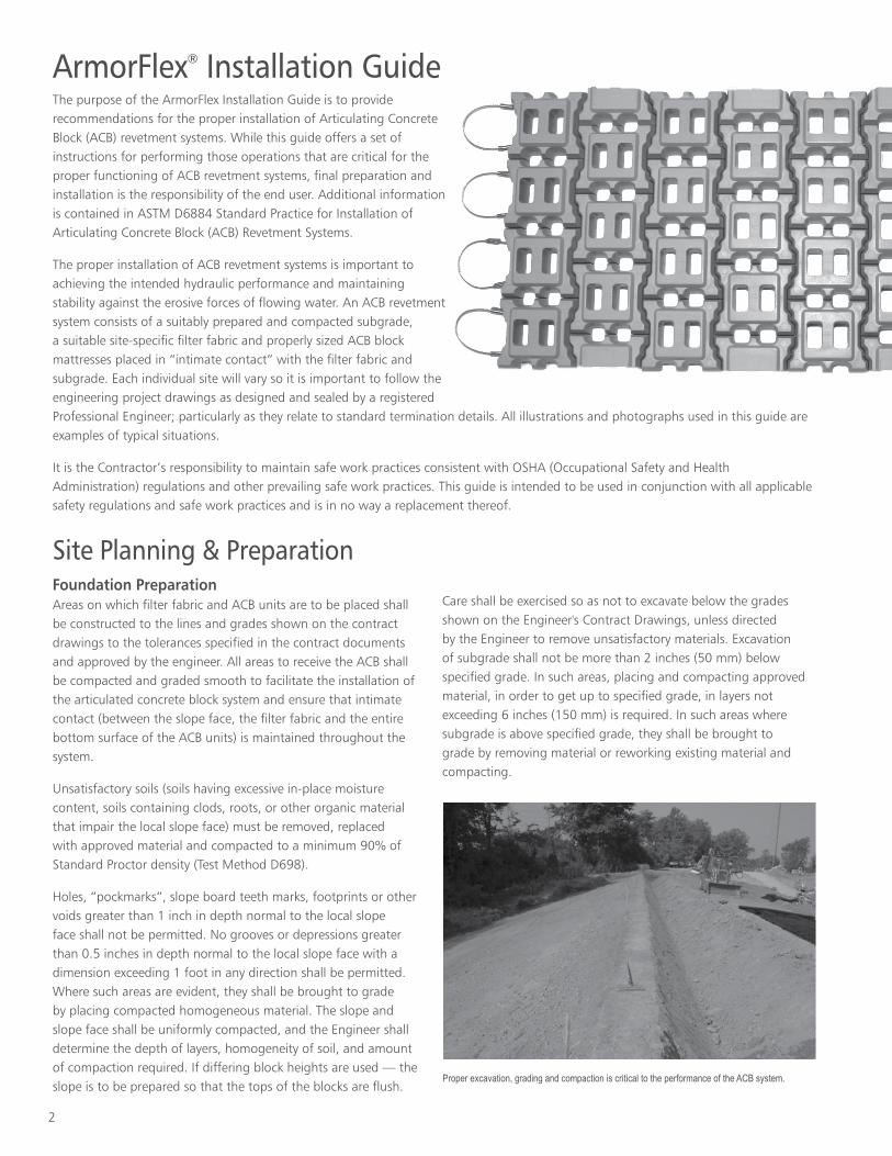
Site Planning & PreparationFoundation Preparation Areas on which filter fabric and ACB units are to be placed shall be constructed to the lines and grades shown on the contract drawings to the tolerances specified in the contract documents and approved by the engineer. All areas to receive the ACB shall be compacted and graded smooth to facilitate the installation of the articulated concrete block system and ensure that intimate contact (between the slope face, the filter fabric and the entire bottom surface of the ACB units) is maintained throughout the system.
Unsatisfactory soils (soils having excessive in-place moisture content, soils containing clods, roots, or other organic material that impair the local slope face) must be removed, replaced with approved material and compacted to a minimum 90% of Standard Proctor density (Test Method D698).
Holes, “pockmarks”, slope board teeth marks, footprints or other voids greater than 1 inch in depth normal to the local slope face shall not be permitted. No grooves or depressions greater than 0.5 inches in depth normal to the local slope face with a dimension exceeding 1 foot in any direction shall be permitted. Where such areas are evident, they shall be brought to grade by placing compacted homogeneous material. The slope and slope face shall be uniformly compacted, and the Engineer shall determine the depth of layers, homogeneity of soil, and amount of compaction required. If differing block heights are used — the slope is to be prepared so that the tops of the blocks are flush.
Care shall be exercised so as not to excavate below the grades shown on the Engineer's Contract Drawings, unless directed by the Engineer to remove unsatisfactory materials. Excavation of subgrade shall not be more than 2 inches (50 mm) below specified grade. In such areas, placing and compacting approved material, in order to get up to specified grade, in layers not exceeding 6 inches (150 mm) is required. In such areas where subgrade is above specified grade, they shall be brought to grade by removing material or reworking existing material and compacting.
Proper excavation, grading and compaction is critical to the performance of the ACB system.
3
When working in an underwater application, it is the contractor’s responsibility to assess the jobsite conditions and the means of achieving proper subgrade preparation, per the Engineer’s Contract drawings, specifications, and tolerances.
Placement of Filter Fabric
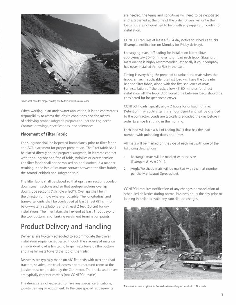
The subgrade shall be inspected immediately prior to filter fabric and ACB placement for proper preparation. The filter fabric shall be placed directly on the prepared subgrade, in intimate contact with the subgrade and free of folds, wrinkles or excess tension. The filter fabric shall not be walked on or disturbed in a manner resulting in the loss of intimate contact between the filter frabric, the ArmorFlex
block and subgrade soils.
The filter fabric shall be placed so that upstream sections overlap downstream sections and so that upslope sections overlap downslope sections (“shingle effect”). Overlaps shall be in the direction of flow wherever possible. The longitudinal and transverse joints shall be overlapped at least 3 feet (91 cm) for below-water installations and at least 2 feet (60 cm) for dry installations. The filter fabric shall extend at least 1 foot beyond the top, bottom, and flanking revetment termination points.
Product Delivery and HandlingDeliveries are typically scheduled to accommodate the overall installation sequence requested though the stacking of mats on an individual load is limited to larger mats towards the bottom and smaller mats toward the top of the trailer.
Deliveries are typically made on 48’ flat beds with over-the-road tractors, so adequate truck access and turnaround room at the jobsite must be provided by the Contractor. The trucks and drivers are typically contract carriers (not CONTECH trucks).
The drivers are not expected to have any special certifications, jobsite training or equipment. In the case special requirements
are needed, the terms and conditions will need to be negotiated and established at the time of the order. Drivers will untie their loads but are not qualified to help with any rigging, unloading or installation.
CONTECH requires at least a full 4 day notice to schedule trucks (Example: notification on Monday for Friday delivery).
For staging mats (offloading for installation later) allow approximately 30-45 minutes to offload each truck. Staging of mats on-site is highly recommended, especially if your company has never installed ArmorFlex in the past.
Timing is everything. Be prepared to unload the mats when the trucks arrive. If applicable, the first load will have the Spreader Bar and filter fabric, along with the first sequence of mats. For installation off the truck, allow 45-60 minutes for direct installation off the truck. Additional time between loads should be considered for inexperienced crews.
CONTECH loads typically allow 2 hours for unloading time. Detention may apply after this 2 hour period and will be charged to the contractor. Loads are typically pre-loaded the day before in order to arrive first thing in the morning.
Each load will have a Bill of Lading (BOL) that has the load number with unloading dates and times.
All mats will be marked on the side of each mat with one of the following descriptions:
1. Rectangle mats will be marked with the size (Example: 8’ W x 20’ L).
2. Angle/Pie shape mats will be marked with the mat number per the Mat Layout Spreadsheet.
CONTECH requires notification of any changes or cancellation of scheduled deliveries during normal business hours the day prior to loading in order to avoid any cancellation charges.
Fabric shall have the proper overlap and be free of any holes or tears.
The use of a crane is optimal for fast and safe unloading and installation of the mats.
4
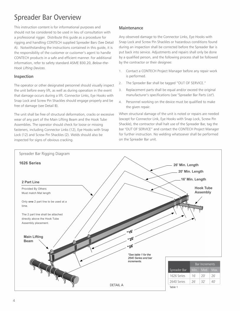
26' Min. Length
2 Part Line
Provided By OthersMust match Mat length
Only one 2 part line to be used at a time.
The 2 part line shall be attached directly above the Hook Tube Assembly placement.
20' Min. Length
16' Min. Length
Hook Tube Assembly
Main Lifting Beam
*16'
* 20'
*26'
*See table 1 for the 2640 Series end bar increments.
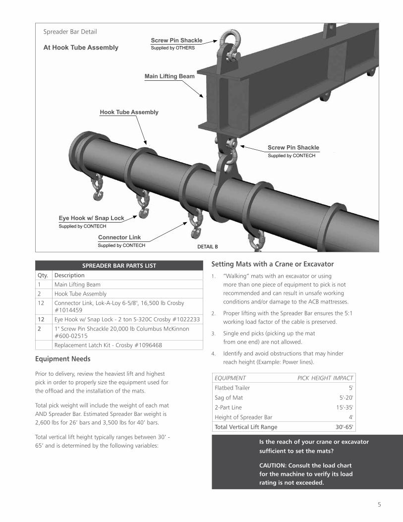
Spreader Bar OverviewThis instruction content is for informational purposes and should not be considered to be used in lieu of consultation with a professional rigger. Distribute this guide as a procedure for rigging and handling CONTECH supplied Spreader Bars (See Detail A). Notwithstanding the instructions contained in this guide, it is the responsibility of the customer or customer’s agent to handle CONTECH products in a safe and efficient manner. For additional information, refer to safety standard ASME B30.20, Below-the-Hook Lifting Devices.
Inspection
The operator or other designated personnel should visually inspect the unit before every lift, as well as during operation in the event that damage occurs during a lift. Connector Links, Eye Hooks with Snap Lock and Screw Pin Shackles should engage properly and be free of damage (see Detail B).
The unit shall be free of structural deformation, cracks or excessive wear of any part of the Main Lifting Beam and the Hook Tube Assemblies. The operator should check for loose or missing fasteners, including Connector Links (12), Eye Hooks with Snap Lock (12) and Screw Pin Shackles (2). Welds should also be inspected for signs of obvious cracking.
Spreader Bar Rigging Diagram
1626 Series
DETAIL A
Maintenance
Any observed damage to the Connector Links, Eye Hooks with Snap Lock and Screw Pin Shackles or hazardous conditions found during an inspection shall be corrected before the Spreader Bar is put back into service. Adjustments and repairs shall only be done by a qualified person, and the following process shall be followed by the contractor or their designee:
1. Contact a CONTECH Project Manager before any repair work is performed.
2. The Spreader Bar shall be tagged “OUT OF SERVICE.”
3. Replacement parts shall be equal and/or exceed the original manufacturer’s specifications (see "Spreader Bar Parts List").
4. Personnel working on the device must be qualified to make the given repair.
When structural damage of the unit is noted or repairs are needed (except for Connector Link, Eye Hooks with Snap Lock, Screw Pin Shackle), the contractor shall halt use of the Spreader Bar, tag the bar "OUT OF SERVICE” and contact the CONTECH Project Manager for further instruction. No welding whatsoever shall be performed on the Spreader Bar unit.
Bar Increments
Spreader Bar Min. Med. Max.
1626 Series 16' 20' 26'
2640 Series 26' 32' 40'Table 1
5
Equipment Needs
Prior to delivery, review the heaviest lift and highest pick in order to properly size the equipment used for the offload and the installation of the mats.
Total pick weight will include the weight of each mat AND Spreader Bar. Estimated Spreader Bar weight is 2,600 lbs for 26’ bars and 3,500 lbs for 40’ bars.
Total vertical lift height typically ranges between 30’ - 65’ and is determined by the following variables:
Setting Mats with a Crane or Excavator
1. “Walking” mats with an excavator or using more than one piece of equipment to pick is not recommended and can result in unsafe working conditions and/or damage to the ACB mattresses.
2. Proper lifting with the Spreader Bar ensures the 5:1 working load factor of the cable is preserved.
3. Single end picks (picking up the mat from one end) are not allowed.
4. Identify and avoid obstructions that may hinder reach height (Example: Power lines).
Main Lifting Beam
Hook Tube Assembly
Supplied by CONTECH
Supplied by CONTECH
Eye Hook w/ Snap Lock
Connector Link
Supplied by CONTECHScrew Pin Shackle
DETAIL B
Spreader Bar Detail
At Hook Tube Assembly
Is the reach of your crane or excavator
sufficient to set the mats?
CAUTION: Consult the load chart for the machine to verify its load rating is not exceeded.
Supplied by OTHERSScrew Pin Shackle
EQUIPMENT PICK HEIGHT IMPACT
Flatbed Trailer 5'
Sag of Mat 5'-20'
2-Part Line 15'-35'
Height of Spreader Bar 4'
Total Vertical Lift Range 30'-65'
SPREADER BAR PARTS LIST
Qty. Description
1 Main Lifting Beam
2 Hook Tube Assembly
12 Connector Link, Lok-A-Loy 6-5/8", 16,500 lb Crosby #1014459
12 Eye Hook w/ Snap Lock - 2 ton S-320C Crosby #1022233
2 1" Screw Pin Shcackle 20,000 lb Columbus McKinnon #600-02515
Replacement Latch Kit - Crosby #1096468
6
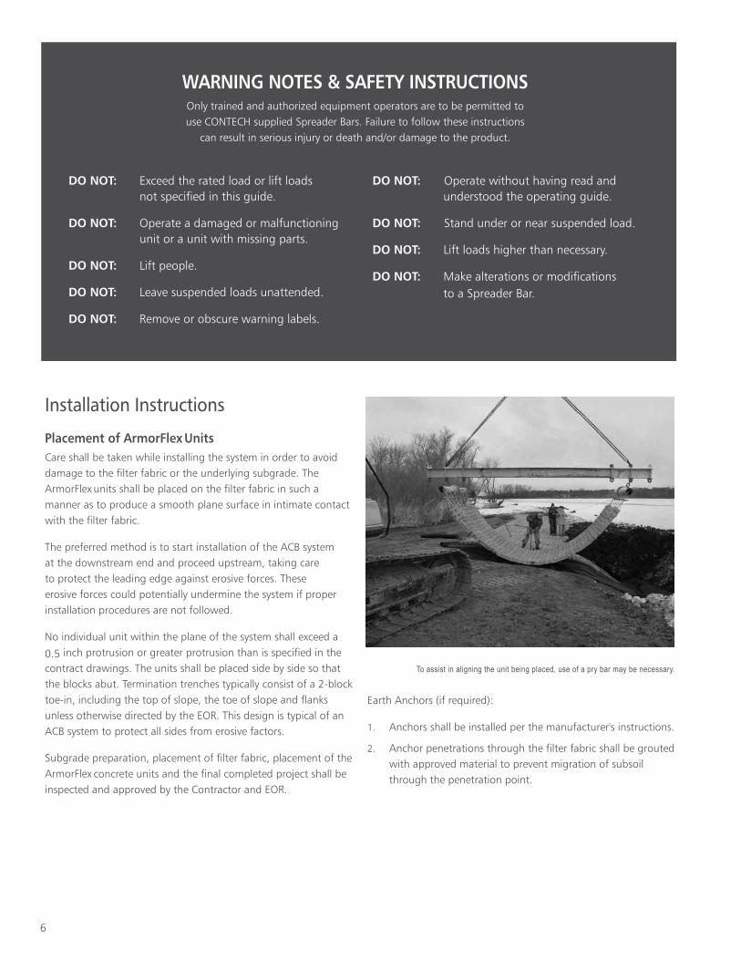
Installation Instructions Placement of ArmorFlex Units Care shall be taken while installing the system in order to avoid damage to the filter fabric or the underlying subgrade. The ArmorFlex
units shall be placed on the filter fabric in such a
manner as to produce a smooth plane surface in intimate contact with the filter fabric.
The preferred method is to start installation of the ACB system at the downstream end and proceed upstream, taking care to protect the leading edge against erosive forces. These erosive forces could potentially undermine the system if proper installation procedures are not followed.
No individual unit within the plane of the system shall exceed a
0.5 inch protrusion or greater protrusion than is specified in the contract drawings. The units shall be placed side by side so that the blocks abut. Termination trenches typically consist of a 2-block toe-in, including the top of slope, the toe of slope and flanks unless otherwise directed by the EOR. This design is typical of an ACB system to protect all sides from erosive factors.
Subgrade preparation, placement of filter fabric, placement of the ArmorFlex
concrete units and the final completed project shall be
inspected and approved by the Contractor and EOR.
DO NOT: Exceed the rated load or lift loads not specified in this guide.
DO NOT: Operate a damaged or malfunctioning unit or a unit with missing parts.
DO NOT: Lift people.
DO NOT: Leave suspended loads unattended.
DO NOT: Remove or obscure warning labels.
DO NOT: Operate without having read and understood the operating guide.
DO NOT: Stand under or near suspended load.
DO NOT: Lift loads higher than necessary.
DO NOT: Make alterations or modifications to a Spreader Bar.
WARNING NOTES & SAFETY INSTRUCTIONSOnly trained and authorized equipment operators are to be permitted to use CONTECH supplied Spreader Bars. Failure to follow these instructions
can result in serious injury or death and/or damage to the product.
Earth Anchors (if required):
1. Anchors shall be installed per the manufacturer's instructions.
2. Anchor penetrations through the filter fabric shall be grouted with approved material to prevent migration of subsoil through the penetration point.
To assist in aligning the unit being placed, use of a pry bar may be necessary.
7
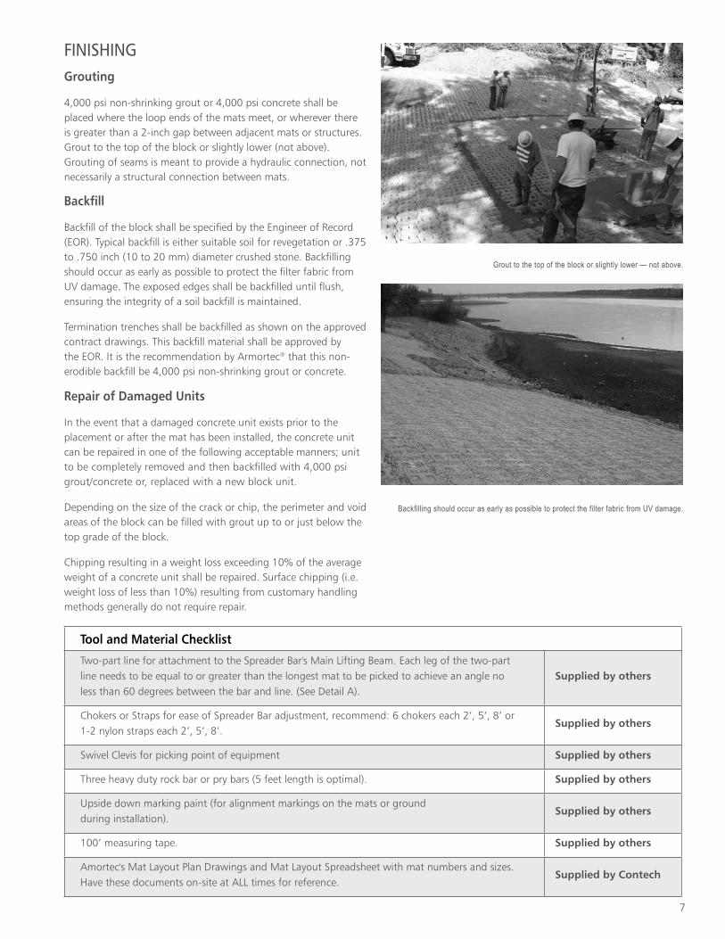
FINISHINGGrouting
4,000 psi non-shrinking grout or 4,000 psi concrete shall be placed where the loop ends of the mats meet, or wherever there is greater than a 2-inch gap between adjacent mats or structures. Grout to the top of the block or slightly lower (not above). Grouting of seams is meant to provide a hydraulic connection, not necessarily a structural connection between mats.
Backfill
Backfill of the block shall be specified by the Engineer of Record (EOR). Typical backfill is either suitable soil for revegetation or .375 to .750 inch (10 to 20 mm) diameter crushed stone. Backfilling should occur as early as possible to protect the filter fabric from UV damage. The exposed edges shall be backfilled until flush, ensuring the integrity of a soil backfill is maintained.
Termination trenches shall be backfilled as shown on the approved contract drawings. This backfill material shall be approved by the EOR. It is the recommendation by Armortec® that this non-erodible backfill be 4,000 psi non-shrinking grout or concrete.
Repair of Damaged Units
In the event that a damaged concrete unit exists prior to the placement or after the mat has been installed, the concrete unit can be repaired in one of the following acceptable manners; unit to be completely removed and then backfilled with 4,000 psi grout/concrete or, replaced with a new block unit.
Depending on the size of the crack or chip, the perimeter and void areas of the block can be filled with grout up to or just below the top grade of the block.
Chipping resulting in a weight loss exceeding 10% of the average weight of a concrete unit shall be repaired. Surface chipping (i.e. weight loss of less than 10%) resulting from customary handling methods generally do not require repair.
Tool and Material Checklist
Two-part line for attachment to the Spreader Bar's Main Lifting Beam. Each leg of the two-part line needs to be equal to or greater than the longest mat to be picked to achieve an angle no less than 60 degrees between the bar and line. (See Detail A).
Supplied by others
Chokers or Straps for ease of Spreader Bar adjustment, recommend: 6 chokers each 2’, 5’, 8’ or 1-2 nylon straps each 2’, 5’, 8’.
Supplied by others
Swivel Clevis for picking point of equipment Supplied by others
Three heavy duty rock bar or pry bars (5 feet length is optimal). Supplied by others
Upside down marking paint (for alignment markings on the mats or ground during installation).
Supplied by others
100’ measuring tape. Supplied by others
Amortec's Mat Layout Plan Drawings and Mat Layout Spreadsheet with mat numbers and sizes. Have these documents on-site at ALL times for reference.
Supplied by Contech
Grout to the top of the block or slightly lower — not above.
Backfilling should occur as early as possible to protect the filter fabric from UV damage.
© 2020 Contech Engineered Solutions LLC, a QUIKRETE Company
armorflex_install PDF 5/20
Notes: —————————————————————————————————————————————————————
—————————————————————————————————————————————————————————
—————————————————————————————————————————————————————————
—————————————————————————————————————————————————————————
—————————————————————————————————————————————————————————
—————————————————————————————————————————————————————————
—————————————————————————————————————————————————————————
—————————————————————————————————————————————————————————
—————————————————————————————————————————————————————————
—————————————————————————————————————————————————————————
—————————————————————————————————————————————————————————
—————————————————————————————————————————————————————————
—————————————————————————————————————————————————————————
—————————————————————————————————————————————————————————
—————————————————————————————————————————————————————————
—————————————————————————————————————————————————————————
—————————————————————————————————————————————————————————
—————————————————————————————————————————————————————————
SupportIf you need guidance please, call your local sales representative or our corporate headquarters at 1.800.338.1122 and ask for a representative.
• Drawings and specifications are available at www.ContechES.com.• Site-specific design support is available from Contech representatives.
Contech Engineered Solutions LLC provides site solutions for the civil engineering industry. Contech’s portfolio includes bridges, drainage, sanitary sewer, stormwater and earth stabilization products.
Nothing in this catalog should be construed as an expressed warranty or an implied warranty of merchantability or fitness for any particular purpose. See the Contech standard quotation or acknowledgement for applicable warranties and other terms and conditions of sale.
www.ContechES.com800.338.1122
ENGINEERED SOLUTIONS