Embed Size (px)
Citation preview
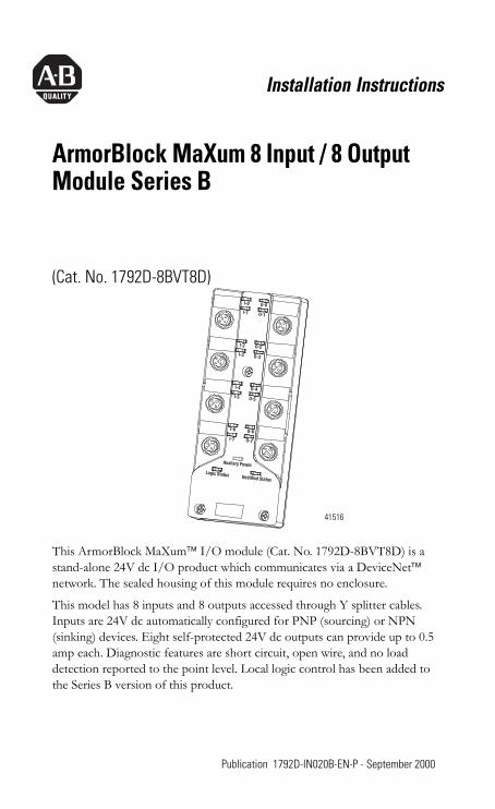
Installation Instructions
ArmorBlock MaXum 8 Input / 8 Output Module Series B
(Cat. No. 1792D-8BVT8D)
This ArmorBlock MaXum™ I/O module (Cat. No. 1792D-8BVT8D) is a stand-alone 24V dc I/O product which communicates via a DeviceNet™ network. The sealed housing of this module requires no enclosure.
This model has 8 inputs and 8 outputs accessed through Y splitter cables. Inputs are 24V dc automatically configured for PNP (sourcing) or NPN (sinking) devices. Eight self-protected 24V dc outputs can provide up to 0.5 amp each. Diagnostic features are short circuit, open wire, and no load detection reported to the point level. Local logic control has been added to the Series B version of this product.
I-4 O-4I-5 O-5
I-2 O-2I-3 O-3
I-0 O-0I-1 O-1
I-6 O-6I-7 O-7
Net/Mod StatusLogic Status
Auxilary Power
41516
1 Publication 1792D-IN020B-EN-P - September 2000
2 ArmorBlock MaXum 8 Input / 8 Output Module Series B
Package ContentsYour package contains:
• 1 ArmorBlock MaXum Module• Installation Instructions
(Note: Cable bases are ordered and shipped separately.)
European Union Directive ComplianceIf this product has the CE mark it is approved for installation within the European Union and EEA regions. It has been designed and tested to meet the following directives.
EMC DirectiveThis product is tested to meet Council Directive 89/336/EEC Electromagnetic Compatibility (EMC) and the following standards, in whole or in part, documented in a technical construction file:
• EN 50081-2 EMC - Generic Emission Standard, Part 2 - Industrial Environment
• EN 50082-2 EMC - Generic Immunity Standard, Part 2 - Industrial Environment
This product is intended for use in an industrial environment.
Low Voltage DirectiveThis product is tested to meet Council Directive 73/23/EEC Low Voltage, by applying the safety requirements of EN 61131-2 Programmable Controllers, Part 2 - Equipment Requirements and Tests.
For specific information required by EN 61131-2, see the appropriate sections in this publication, as well as the following Allen-Bradley publications:
• Industrial Automation Wiring and Grounding Guidelines For Noise Immunity, publication 1770-4.1
• Automation Systems Catalog, publication B113
Publication 1792D-IN020B-EN-P - September 2000
ArmorBlock MaXum 8 Input / 8 Output Module Series B 3
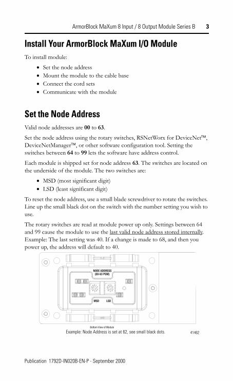
Install Your ArmorBlock MaXum I/O ModuleTo install module:
• Set the node address• Mount the module to the cable base• Connect the cord sets• Communicate with the module
Set the Node AddressValid node addresses are 00 to 63.
Set the node address using the rotary switches, RSNetWorx for DeviceNet™, DeviceNetManager™, or other software configuration tool. Setting the switches between 64 to 99 lets the software have address control.
Each module is shipped set for node address 63. The switches are located on the underside of the module. The two switches are:
• MSD (most significant digit)• LSD (least significant digit)
To reset the node address, use a small blade screwdriver to rotate the switches. Line up the small black dot on the switch with the number setting you wish to use.
The rotary switches are read at module power up only. Settings between 64 and 99 cause the module to use the last valid node address stored internally. Example: The last setting was 40. If a change is made to 68, and then you power up, the address will default to 40.
NODE ADDRESS(00-63 PGM)
LSDMSD
0 123
45
89
76
0 123
45
89
76
Bottom View of Module
41462Example: Node Address is set at 62, see small black dots.
Publication 1792D-IN020B-EN-P - September 2000
4 ArmorBlock MaXum 8 Input / 8 Output Module Series B
The module is equipped with AutoBaud detect. AutoBaud lets the module read the settings already in use on your DeviceNet network and automatically adjusts to follow those settings.
Install the ModuleThis module mounts to the following cable bases:
• 1792D-CBFM for KwikLink™ flat media installation• 1792D-CB12 for 12mm drop cable installation• 1792D-CB18P for round media DeviceNet and output power• or other optional cable base assembly.
To install the module:
1. Position the module over the mounted cable base. Align the three captive screws in the module with the accepting receptacles in the base.
2. Tighten the screws with a torque of 8 inch-pounds to secure the module to the base.
IMPORTANT The cable base should already be installed. See publication 1792D-IN009B-EN-P to install the cable base.
IMPORTANT Proper alignment of the screws is necessary to complete the connections between the module contacts and the cable contacts.
Publication 1792D-IN020B-EN-P - September 2000
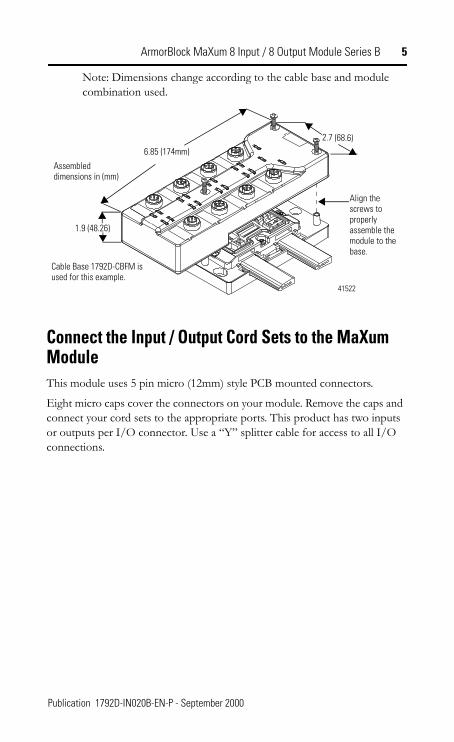
ArmorBlock MaXum 8 Input / 8 Output Module Series B 5
Note: Dimensions change according to the cable base and module combination used.
Connect the Input / Output Cord Sets to the MaXum ModuleThis module uses 5 pin micro (12mm) style PCB mounted connectors.
Eight micro caps cover the connectors on your module. Remove the caps and connect your cord sets to the appropriate ports. This product has two inputs or outputs per I/O connector. Use a “Y” splitter cable for access to all I/O connections.
Align the screws to properly assemble the module to the base.
Cable Base 1792D-CBFM is used for this example.
Assembled dimensions in (mm)
1.9 (48.26)
2.7 (68.6)6.85 (174mm)
41522
Publication 1792D-IN020B-EN-P - September 2000
6 ArmorBlock MaXum 8 Input / 8 Output Module Series B
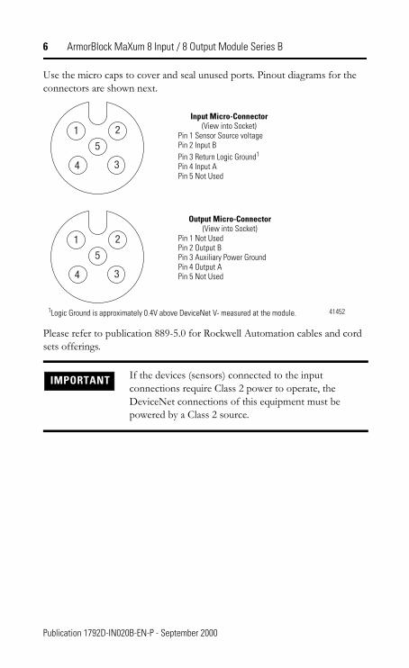
Use the micro caps to cover and seal unused ports. Pinout diagrams for the connectors are shown next.
Please refer to publication 889-5.0 for Rockwell Automation cables and cord sets offerings.
IMPORTANT If the devices (sensors) connected to the input connections require Class 2 power to operate, the DeviceNet connections of this equipment must be powered by a Class 2 source.
Input Micro-Connector(View into Socket)
Pin 1 Sensor Source voltagePin 2 Input BPin 3 Return Logic Ground1
Pin 4 Input APin 5 Not Used
Output Micro-Connector(View into Socket)
Pin 1 Not UsedPin 2 Output BPin 3 Auxiliary Power GroundPin 4 Output APin 5 Not Used
414521Logic Ground is approximately 0.4V above DeviceNet V- measured at the module.
Publication 1792D-IN020B-EN-P - September 2000
ArmorBlock MaXum 8 Input / 8 Output Module Series B 7
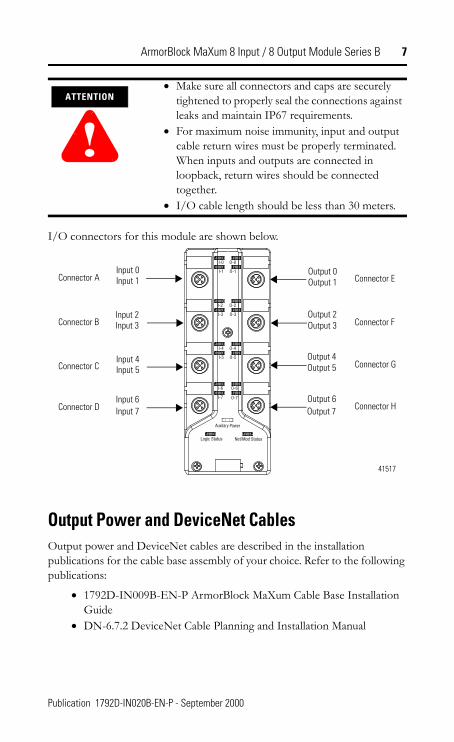
I/O connectors for this module are shown below.
Output Power and DeviceNet CablesOutput power and DeviceNet cables are described in the installation publications for the cable base assembly of your choice. Refer to the following publications:
• 1792D-IN009B-EN-P ArmorBlock MaXum Cable Base Installation Guide
• DN-6.7.2 DeviceNet Cable Planning and Installation Manual
ATTENTION
!• Make sure all connectors and caps are securely
tightened to properly seal the connections against leaks and maintain IP67 requirements.
• For maximum noise immunity, input and output cable return wires must be properly terminated. When inputs and outputs are connected in loopback, return wires should be connected together.
• I/O cable length should be less than 30 meters.
I-4
I-5
I-6
I-7
O-4
O-5
I-2
I-3
O-2
O-3
O-6
O-7
Logic Status Net/Mod Status
I-0
I-1
O-0
O-1
Auxilary Power
41517
Input 0Input 1
Input 2Input 3
Input 4Input 5
Input 6Input 7
Output 0Output 1
Output 2Output 3
Output 4Output 5
Output 6Output 7
Connector A
Connector B
Connector C
Connector D
Connector E
Connector F
Connector G
Connector H
Publication 1792D-IN020B-EN-P - September 2000
8 ArmorBlock MaXum 8 Input / 8 Output Module Series B
Communicate With Your ArmorBlock MaXum I/O ModuleThis ArmorBlock module’s I/O is exchanged with the master through a poll, change-of-state, or cyclic connection.
The module consumes and produces I/O data as follows:
Cyclic - allows configuration of the block as an I/O client. The block will produce and consume its I/O cyclically at the rate configured.
Polled - a master initiates communication by sending its polled I/O message to the module. The 8 input / 8 output module consumes the message, updates outputs, and produces a response. The response has input data, input faults, output faults, and the status of the Auxiliary power.
Change-of-State - productions occur when an input changes or a fault condition occurs. If no input or fault condition change occurs within the expected packet rate, a heartbeat production occurs. This heartbeat production tells the scanner module that the I/O module is alive and ready to communicate. Consumption occurs when data changes and the master produces new output data to the I/O block.
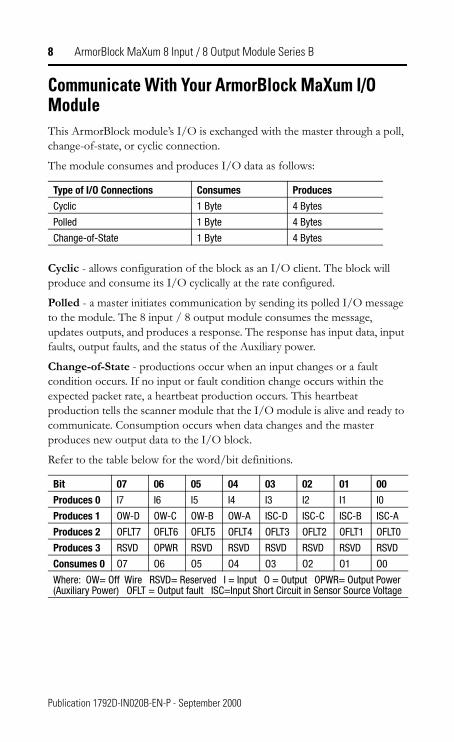
Refer to the table below for the word/bit definitions.
Type of I/O Connections Consumes Produces
Cyclic 1 Byte 4 Bytes
Polled 1 Byte 4 Bytes
Change-of-State 1 Byte 4 Bytes
Bit 07 06 05 04 03 02 01 00
Produces 0 I7 I6 I5 I4 I3 I2 I1 I0
Produces 1 OW-D OW-C OW-B OW-A ISC-D ISC-C ISC-B ISC-A
Produces 2 OFLT7 OFLT6 OFLT5 OFLT4 OFLT3 OFLT2 OFLT1 OFLT0
Produces 3 RSVD OPWR RSVD RSVD RSVD RSVD RSVD RSVD
Consumes 0 O7 O6 O5 O4 O3 O2 O1 O0
Where: OW= Off Wire RSVD= Reserved I = Input O = Output OPWR= Output Power (Auxiliary Power) OFLT = Output fault ISC=Input Short Circuit in Sensor Source Voltage
Publication 1792D-IN020B-EN-P - September 2000
ArmorBlock MaXum 8 Input / 8 Output Module Series B 9
The DeviceNet Network uses advanced network technology, producer/consumer communication, to increase network functionality and throughput. Visit our web site at http://www.ab.com/networks for producer/consumer technology information and updates.
Byte Bit Description
Produces 0 00-07 Input Status bits: When the bit is set (1), the input is on. Bit 00 = to input 0, bit 01 = to input 1, bit 02 = to input 2, bit 03 = to input 3, bit 04 = to input 4, bit 05 = to input 5, bit 06 = to input 6, bit 07 = to input 7.
Produces 1 00-03
04-07
Input short circuit fault: ISC-A = a short circuit for connector AInput short circuit fault: ISC-B = a short circuit for connector BInput short circuit fault: ISC-C = a short circuit for connector CInput short circuit fault: ISC-D = a short circuit for connector DInput off wire fault: OW-A = an off-wire fault for connector AInput off wire fault: OW-B = an off-wire fault for connector BInput off wire fault: OW-C = an off-wire fault for connector CInput off wire fault: OW-D = an off-wire fault for connector D
Produces 2 00-07 Output no load or overload fault (OFLT): - When the bit is set (1) an output fault has occurred. OFLT0 = to output 0, OFLT1 = to output 1, OFLT2 corresponds to output 2, OFLT3 = to output 3, OFLT4 = to output 4, OFLT5 = to output 5, OFLT6 = to output 6, OFLT7 = to output 7.
Produces 3 00-0506
07
RSVD = ReservedOutput Power Fault (OPWR): When the bit is set (1) Auxiliary Power is not present. RSVD = Reserved
Consumes 0 00-07 Output bits: When the bit is set (1), the output will be turned on. Bit 00 corresponds to output O0, bit 01 corresponds to output 01, bit 02 to output 02, bit 03 to output 03, bit 04 to output 04, bit 05 to output 05, bit 06 to output 06, bit 07 to output 07.
Publication 1792D-IN020B-EN-P - September 2000
10 ArmorBlock MaXum 8 Input / 8 Output Module Series B
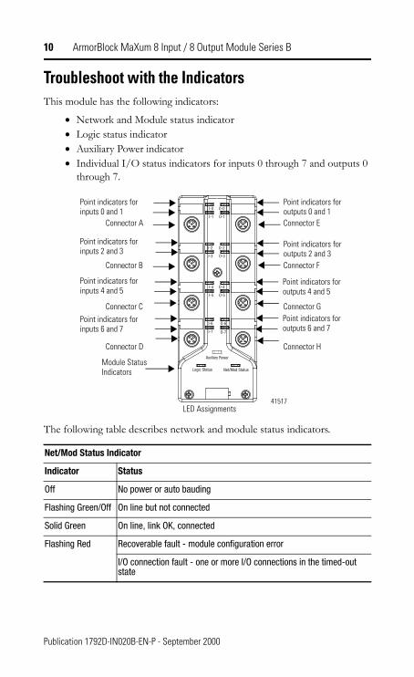
Troubleshoot with the IndicatorsThis module has the following indicators:
• Network and Module status indicator• Logic status indicator• Auxiliary Power indicator• Individual I/O status indicators for inputs 0 through 7 and outputs 0
through 7.
The following table describes network and module status indicators.
Net/Mod Status Indicator
Indicator Status
Off No power or auto bauding
Flashing Green/Off On line but not connected
Solid Green On line, link OK, connected
Flashing Red Recoverable fault - module configuration error
I/O connection fault - one or more I/O connections in the timed-out state
I-4
I-5
I-6
I-7
O-4
O-5
I-2
I-3
O-2
O-3
O-6
O-7
Logic Status Net/Mod Status
I-0
I-1
O-0
O-1
Auxilary Power
41517
Point indicators for inputs 0 and 1
Module Status Indicators
Connector A
Connector B
Connector C
Connector D
Connector E
Connector F
Connector G
Connector H
Point indicators for inputs 2 and 3
Point indicators for inputs 4 and 5
Point indicators for inputs 6 and 7
Point indicators for outputs 6 and 7
Point indicators for outputs 4 and 5
Point indicators for outputs 2 and 3
Point indicators for outputs 0 and 1
LED Assignments
Publication 1792D-IN020B-EN-P - September 2000
ArmorBlock MaXum 8 Input / 8 Output Module Series B 11
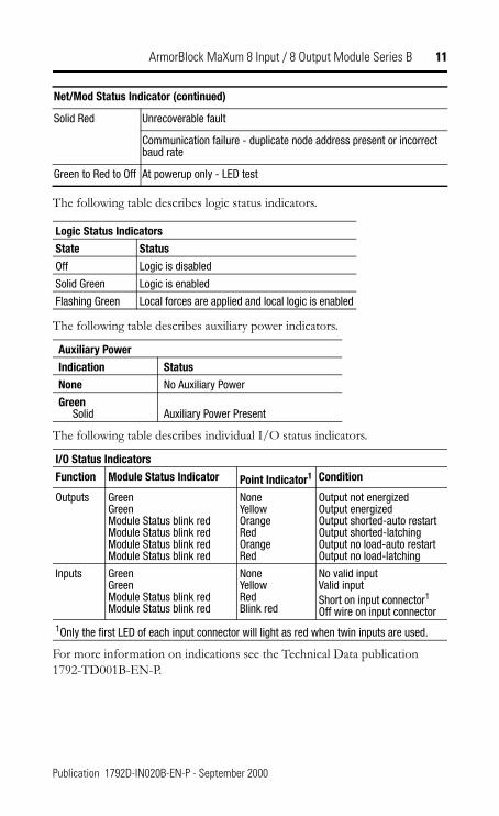
The following table describes logic status indicators.
The following table describes auxiliary power indicators.
The following table describes individual I/O status indicators.
For more information on indications see the Technical Data publication 1792-TD001B-EN-P.
Net/Mod Status Indicator (continued)
Solid Red Unrecoverable fault
Communication failure - duplicate node address present or incorrect baud rate
Green to Red to Off At powerup only - LED test
Logic Status Indicators
State Status
Off Logic is disabled
Solid Green Logic is enabled
Flashing Green Local forces are applied and local logic is enabled
Auxiliary Power
Indication Status
None No Auxiliary Power
Green Solid Auxiliary Power Present
I/O Status Indicators
Function Module Status Indicator Point Indicator1 Condition
Outputs GreenGreenModule Status blink redModule Status blink redModule Status blink redModule Status blink red
NoneYellowOrangeRedOrangeRed
Output not energizedOutput energizedOutput shorted-auto restartOutput shorted-latchingOutput no load-auto restartOutput no load-latching
Inputs GreenGreenModule Status blink redModule Status blink red
NoneYellowRedBlink red
No valid inputValid inputShort on input connector1
Off wire on input connector1Only the first LED of each input connector will light as red when twin inputs are used.
Publication 1792D-IN020B-EN-P - September 2000
12 ArmorBlock MaXum 8 Input / 8 Output Module Series B
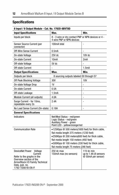
Specifications
8 Input / 8 Output Module - Cat. No. 1792D-8BVT8D
Input Specifications Max. Min.
Inputs per block 8 - 3 wire or dry contact PNP or NPN devices or 4 - 4 wire PNP or NPN devices
Sensor Source Current (per connector)
100mA total -
Off-Wire Sense Current 0.5mA -
On-state Voltage 25V dc 10V dc
On-state Current 10mA 2mA
Off-state Voltage 5V dc -
Off-state Current - 1.5mA
Output Specifications Max. Min.Outputs per block 8 sourcing outputs labeled O0 through O7
Off Peak Blocking Voltage 30V 10V
On-state Voltage Drop 1V -
On-state Current 0.5A -
Off-state Leakage 1.5mA -
Module Current (all outputs) 4.0A -
Surge Current - for 10ms, repeatable every 2s
2.4A -
No Load Sense Current (On-state) 0.18A -
General SpecificationsIndicators Net/Mod Status - red/green
Logic Status - red/greenAuxiliary Power - greenPoint LED - yellow/orange/red
Communication Rate •125Kbps @ 500 meters(1600 feet) for thick cable, flat media length 375 meters (1230 feet)•250Kbps @ 200 meters(600 feet) for thick cable, flat media length 150 meters (492 feet)•500Kbps @ 100 meters (330 feet) for thick cable, flat media length 75 meters (246 feet)
DeviceNet Power Voltage CurrentRefer to the graphs in the Overview section of the ArmorBlock I/O Family Technical Data, pub. no. 1792-TD001B-EN-P.
25V dc max150mA max (no sensors)
11V dc minup to 1.4A (8 sensors @ 50mA per sensor)
Publication 1792D-IN020B-EN-P - September 2000
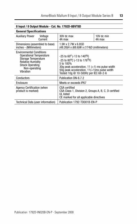
ArmorBlock MaXum 8 Input / 8 Output Module Series B 13
General SpecificationsAuxiliary Power Voltage Current
30V dc max4A max
10V dc min4A max
Dimensions (assembled to base)inches - (Millimeters)
1.9H x 2.7W x 6.85D (48.26)H x (68.6)W x (174)D (millimeters)
Environmental Conditions Operational Temperature Storage Temperature Relative Humidity Shock Operating Non-operating Vibration
-25 to 60o (-13 to 140oF)-25 to 80oC (-13 to 176OF)5 to 100%30g peak acceleration, 11 (+1) ms pulse width50g peak acceleration, 11(+1)ms pulse widthTested 10g @ 10-500Hz per IEC 68-2-6
Conductors Publication DN-6.7.2
Enclosure Meets or exceeds IP67
Agency Certification (when product is marked)
CSA certifiedCSA Class 1, Division 2, Groups A, B, C, D certifiedUL listedCE marked for all applicable directives
Technical Data (user information) Publication 1792-TD001B-EN-P
8 Input / 8 Output Module - Cat. No. 1792D-8BVT8D
Publication 1792D-IN020B-EN-P - September 2000
14 ArmorBlock MaXum 8 Input / 8 Output Module Series B
Hazardous Location Approval The following information applies only to products marked with Hazardous Location Approval, when operating in hazardous locations:
Products marked “CL I, DIV 2, GP A, B, C, D” are suitable for use in Class I Division 2 Groups A, B, C, D, Hazardous Locations and nonhazardous locations only. Each product is supplied with markings on the rating nameplate indicating the hazardous location temperature code. When combining products within a system, the most adverse temperature code (lowest “T” number) may be used to help determine the overall temperature code of the system. Combinations of equipment in your system are subject to investigation by the local Authority Having Jurisdiction at the time of installation.
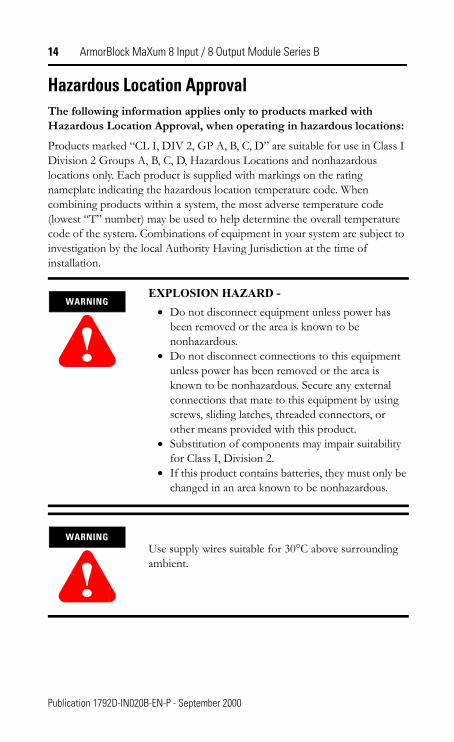
WARNING
!EXPLOSION HAZARD -
• Do not disconnect equipment unless power has been removed or the area is known to be nonhazardous.
• Do not disconnect connections to this equipment unless power has been removed or the area is known to be nonhazardous. Secure any external connections that mate to this equipment by using screws, sliding latches, threaded connectors, or other means provided with this product.
• Substitution of components may impair suitability for Class I, Division 2.
• If this product contains batteries, they must only be changed in an area known to be nonhazardous.
WARNING
!Use supply wires suitable for 30°C above surrounding ambient.
Publication 1792D-IN020B-EN-P - September 2000
ArmorBlock MaXum 8 Input / 8 Output Module Series B 15
Les informations suivantes ne concernent que les produits marqués pour une utilisation en environnements dangereux :
Les produits marqués « CL I, DIV 2, GP A, B, C, D » ne conviennent qu’à une utilisation en environnements de Classe I Division 2 Groupes A, B, C, D dangereux et non dangereux. Chaque produit est livré avec des marquages sur sa plaque d’identification qui indiquent le code de température pour les environnements dangereux. Lorsque plusieurs produits sont combinés dans un système, le code de température le plus défavorable (code de température le plus faible) peut être utilisé pour déterminer le code de température global du système. Les combinaisons d’équipements dans le système sont sujettes à inspection par les autorités locales qualifiées au moment de l’installation.
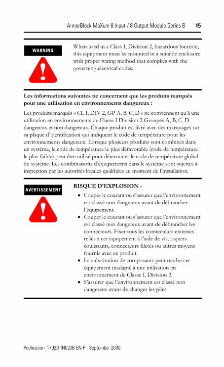
WARNING
!When used in a Class I, Division 2, hazardous location, this equipment must be mounted in a suitable enclosure with proper wiring method that complies with the governing electrical codes.
AVERTISSEMENT
!RISQUE D’EXPLOSION -
• Couper le courant ou s’assurer que l’environnement est classé non dangereux avant de débrancher l’équipement.
• Couper le courant ou s’assurer que l’environnement est classé non dangereux avant de débrancher les connecteurs. Fixer tous les connecteurs externes reliés à cet équipement à l’aide de vis, loquets coulissants, connecteurs filetés ou autres moyens fournis avec ce produit.
• La substitution de composants peut rendre cet équipement inadapté à une utilisation en environnement de Classe I, Division 2.
• S’assurer que l’environnement est classé non dangereux avant de changer les piles.
Publication 1792D-IN020B-EN-P - September 2000
This product has been tested at an Open DeviceNet Vendor Association, Inc. (ODVA) authorized independent test laboratory and found to comply with ODVA Conformance Test. Please contact the ODVA website (http://www.odva.org) for listing of products tested by ODVA independent test labs for further details.
AVERTISSEMENT
!Utiliser des fils d’alimentation qui conviennent à une température de 30°C au-dessus de la température ambiante.
AVERTISSEMENT
!Pour une utilisation en environnement de classe i, division 2 dangereux, cet equipement doit etre monte dans un boitier avec un cablage approprie conforme aux normes electriques en vigueur.
Publication 1792D-IN020B-EN-P - September 2000 PN 957395-54Supersedes Publication 1792D-5.20 - October 1998 © 2000 Rockwell International Corporation. Printed in USA


![0$;80 HGLWLRQ,, 3UR]HVV *DV &KURPDWRJUDSK · • Advance MAXUM edition II Automatic Purge Unit 7KHPD 6HLWH Aufstellungsort 2 MAXUM edition II – Technische Daten 3 MAXUM edition](https://img.pdfslide.us/doc/110x75/5e8286168302c80e5f195a6a/080-hglwlrq-3urhvv-dv-kurpdwrjudsk-a-advance-maxum-edition-ii-automatic.jpg)