Embed Size (px)
Citation preview
DS7080i Version 2+Security System User’s
GuideAn instruction guide For your alarm system
when used with aDS7447, DS7443S or DS7445 keypad
Armed
Status
Power
Fire
1 2 3
4 5 6
7 8 9
0* #
On
NoEntry
SystemReset
Bypass
OnlyPerimeter
Off
Ready To Arm
Page 2
System Overview
Congratulations on the installation of your new security system. No other investment can provide such peace ofmind. Welcome to the DS7080i Version 2+ intrusion/fire control system. Since each installation is unique, your’s will contain
some, but not necessarily all of the features mentioned in this guide.
A security system usually consists of:
• A Control Panel: The control panel is the center of your intrusion/fire alarm system. It supports such vital functions as receiving trouble andalarm signals from detectors, the sounding of bells and/or sirens, and communicating with your alarm monitoring company.
• Command Control Stations (Keypads): The keypad is where you interact with the system. The keypad displays critical information concern-ing the operation of your alarm system, plus it allows you to initiate commands such as arming and disarming.
• Protected Zones: Your security system may contain protected windows and doors (perimeter zones), plus various internal sensors. Yourcontrol panel separates perimeter zones from interior protection zones. Specific protection devices may include:
• glass breakage sensors: Devices that detect the sound of breaking glass.
• interior motion sensors: Electronic sensors (e.g. passive infrared) that detect movement within an interior zone.
• magnetic contacts: Switches used to detect the opening of doors or windows.
• smoke detectors: Devices that detect products of combustion.
This system includes a telephone line seizure feature. The system may be programmed to communicate with a central monitoringstation to report system events. You will not be able to use your phone while the system is communicating with the central monitoringstation. In the unlikely event that the central station is not able to receive the report, your phone may be unavailable for up to 20minutes while the panel makes additional communication attempts.
Page 3
Table of Contents
Your system may or may not be monitored by an alarm monitoring service.If it is not monitored, it is vital to understand the following:
• Alarms sound only at your location.• When an alarm is sounded, no signals are sent out.• Duress and other silent alarms are disabled.• Emergency alarms sound only at your location.
System Overview 2Understanding the DS7447, DS7443S and DS7445 Keypads 4Understanding Partitioning 6Turning ON (arming) your System 7Turning ON (arming) your System (continued) 8Quick Arming Your System 9Turning OFF (disarming) your System / Silencing Alarms 10Force Arming your System 11Zone Bypass 12Chime Mode 13Access Control 14Changing the Date 15Changing the Time 16Automatic Arming 17Delaying Automatic Arming 18Setting Delayed Arming 19Emergency Procedures 20Turning OFF (disarming) your System under Duress 21
Fire Reset / Fire Trouble 23Fire Safety 24Personal Identification Numbers 26Removing a PIN 26Error Displays 29Testing Your System 30Event History Readback 33Glossary 34Quick Reference Guide 35System Features Reference Guide 36Index 38
Page 4
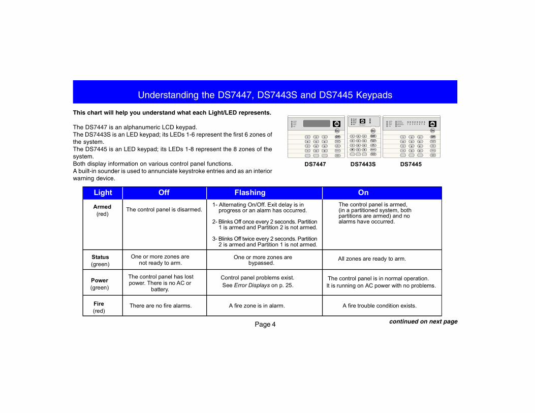
This chart will help you understand what each Light/LED represents.
The DS7447 is an alphanumeric LCD keypad.The DS7443S is an LED keypad; its LEDs 1-6 represent the first 6 zones ofthe system.The DS7445 is an LED keypad; its LEDs 1-8 represent the 8 zones of thesystem.Both display information on various control panel functions.A built-in sounder is used to annunciate keystroke entries and as an interiorwarning device.
Understanding the DS7447, DS7443S and DS7445 Keypads
continued on next page
The control panel is disarmed.1- Alternating On/Off. Exit delay is in progress or an alarm has occurred.
2- Blinks Off once every 2 seconds. Partition 1 is armed and Partition 2 is not armed.
3- Blinks Off twice every 2 seconds. Partition 2 is armed and Partition 1 is not armed.
Light Off Flashing On
Armed(red)
The control panel is armed,(in a partitioned system, bothpartitions are armed) and noalarms have occurred.
Fire(red)
There are no fire alarms.
Power(green)
Status(green)
One or more zones arenot ready to arm.
The control panel has lostpower. There is no AC or
battery.
One or more zones arebypassed.
Control panel problems exist.See Error Displays on p. 25.
The control panel is in normal operation.It is running on AC power with no problems.
All zones are ready to arm.
A fire zone is in alarm. A fire trouble condition exists.
DS7447 DS7445DS7443S
Armed
Status
Po wer
Fire
P erimeter
S upervisory
Bell S ilenced
Trouble
1 2 3 4 5 6 7 8
1 2 3
4 5 6
7 8 9
0* #
On
NoEntry
SystemReset
Bypass
OnlyPerimeter
Off
Armed
Status
Power
Fire
1 2 3
4 5 6
7 8 9
0* #
On
NoEntry
S ystemReset
B ypass
OnlyP erim eter
Off
On
NoEntry
SystemReset
Bypass
PerimeterOnly
Off
654
987
#0*
123
456
321
Fire
ArmedStatusPower
TEST WEEKLY
Page 5
Understanding the DS7447, DS7443S and DS7445 Keypads (continued)
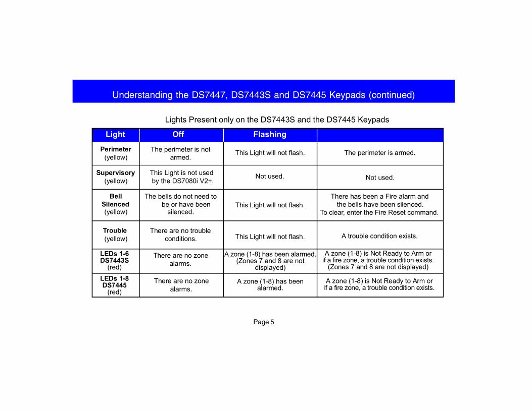
The perimeter is notarmed.
This Light is not usedby the DS7080i V2+.
The bells do not need tobe or have been
silenced.
There are no troubleconditions.
There are no zonealarms.
This Light will not flash.
Not used.
This Light will not flash.
This Light will not flash.
A zone (1-8) has been alarmed.(Zones 7 and 8 are not
displayed)
Perimeter(yellow)
Supervisory(yellow)
BellSilenced(yellow)
Trouble(yellow)
LEDs 1-6DS7443S
(red)
The perimeter is armed.
Not used.
There has been a Fire alarm andthe bells have been silenced.
To clear, enter the Fire Reset command.
A trouble condition exists.
A zone (1-8) is Not Ready to Arm orif a fire zone, a trouble condition exists.
(Zones 7 and 8 are not displayed)
Lights Present only on the DS7443S and the DS7445 Keypads
Light Off Flashing
LEDs 1-8DS7445
(red)A zone (1-8) has been
alarmed.A zone (1-8) is Not Ready to Arm orif a fire zone, a trouble condition exists.
There are no zonealarms.
Page 6
Understanding PartitioningYour alarm system may be Partitioned.
A Partitioned system is a system that is divided into two areas which may be armed and disarmed independently.
The following applies in a Partitioned system:
• User PIN numbers are always required to perform operations in a Partitioned system.
• DS7447 LCD keypads will alternately display (about every 2 seconds) the current status of each partition.
• DS7443S and DS7445 LED keypads will alternately display (about every 2 seconds) the current status of each partition by way of the LED’s.See “Understanding the DS7447, DS7443S and DS7445 Keypads” on pages 4 and 5 for details.
• If the User PIN has authority in only one Partition, using that PIN on any keypad will perform Arming and Disarming commands only for thePartition in which the User has authority.
• If the User PIN has authority in both Partitions, the User may arm or disarm both Partitions by entering the commands from any keypad.
• Only Users with access to both partitions can arm common zones.
• If the User PIN has authority in both Partitions, the User may arm or disarm the first Partition only by entering the PIN number + [##] + thearming/disarming command. To perform arming or disarming commands in the second Partition only, enter the PIN number + [####] + thearming/disarming command.
• If Custom Arming (PIN + [#] [4]) is used in a Partitioned system, the following will apply:- Users with access to both partitions can Custom Arm all zones.- Users with access to both partitions cannot custom arm a single partition.- Users with access to Partition 1 can Custom Arm any zones in Partition 1 but cannot arm common zones or zones in Partition 2.- Users with access to Partition 2 can Custom Arm any zones in Partition 2 but cannot arm common zones or zones in Partition 1.
Page 7
Turning ON (arming) your System
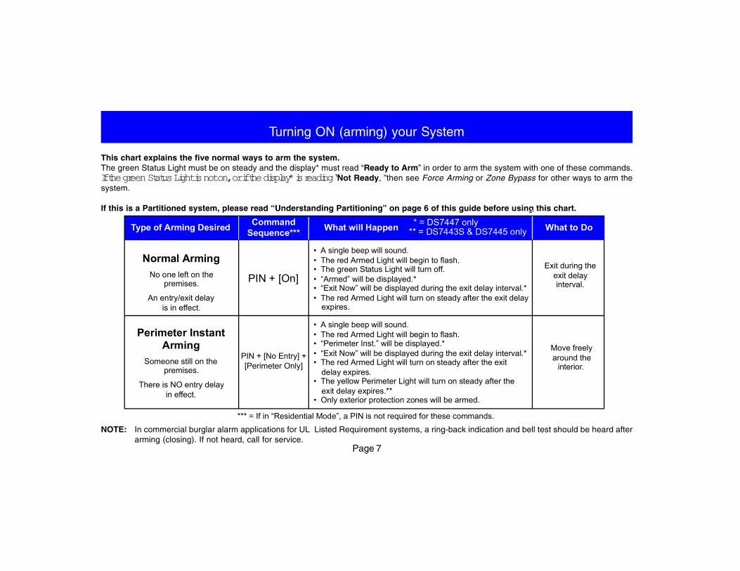
This chart explains the five normal ways to arm the system.The green Status Light must be on steady and the display* must read “Ready to Arm” in order to arm the system with one of these commands.If the green Status Light is not on, or if the display* is reading “Not Ready, ”then see Force Arming or Zone Bypass for other ways to arm thesystem.
If this is a Partitioned system, please read “Understanding Partitioning” on page 6 of this guide before using this chart.
NOTE: In commercial burglar alarm applications for UL Listed Requirement systems, a ring-back indication and bell test should be heard afterarming (closing). If not heard, call for service.
*** = If in “Residential Mode”, a PIN is not required for these commands.
Type of Arming Desired
Exit during theexit delayinterval.
Normal ArmingNo one left on the
premises.
An entry/exit delayis in effect.
Perimeter InstantArming
Someone still on thepremises.
There is NO entry delayin effect.
Move freelyaround the
interior.
PIN + [On]
PIN + [No Entry] +[Perimeter Only]
• A single beep will sound.• The red Armed Light will begin to flash.• The green Status Light will turn off.• “Armed” will be displayed.*• “Exit Now” will be displayed during the exit delay interval.*• The red Armed Light will turn on steady after the exit delay
expires.
CommandSequence***
• A single beep will sound.• The red Armed Light will begin to flash.• “Perimeter Inst.” will be displayed.*• “Exit Now” will be displayed during the exit delay interval.*• The red Armed Light will turn on steady after the exit
delay expires.• The yellow Perimeter Light will turn on steady after the
exit delay expires.**• Only exterior protection zones will be armed.
What to Do* = DS7447 only** = DS7443S & DS7445 onlyWhat will Happen
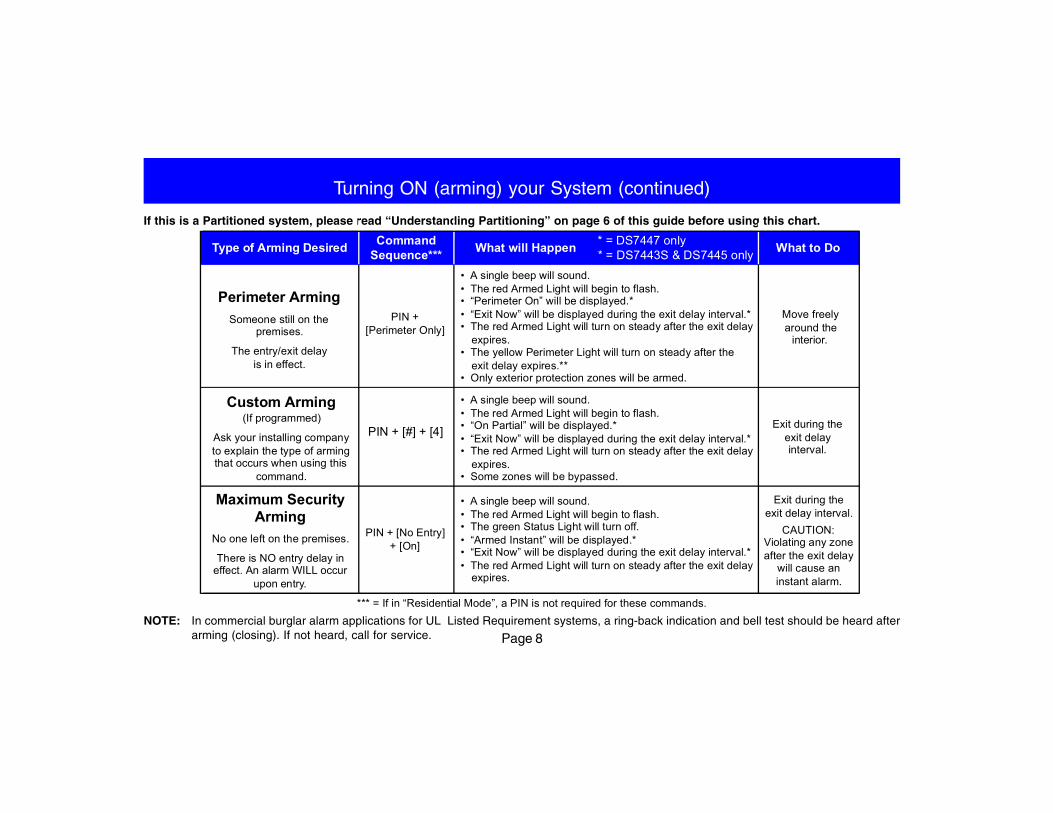
Page 8NOTE: In commercial burglar alarm applications for UL Listed Requirement systems, a ring-back indication and bell test should be heard after
arming (closing). If not heard, call for service.
If this is a Partitioned system, please read “Understanding Partitioning” on page 6 of this guide before using this chart.
Turning ON (arming) your System (continued)
What to DoType of Arming Desired
Perimeter ArmingSomeone still on the
premises.
The entry/exit delayis in effect.
• A single beep will sound.• The red Armed Light will begin to flash.• “Perimeter On” will be displayed.*• “Exit Now” will be displayed during the exit delay interval.*• The red Armed Light will turn on steady after the exit delay
expires.• The yellow Perimeter Light will turn on steady after the
exit delay expires.**• Only exterior protection zones will be armed.
Custom Arming(If programmed)
Ask your installing companyto explain the type of armingthat occurs when using this
command.
• A single beep will sound.• The red Armed Light will begin to flash.• “On Partial” will be displayed.*• “Exit Now” will be displayed during the exit delay interval.*• The red Armed Light will turn on steady after the exit delay
expires.• Some zones will be bypassed.
Maximum SecurityArming
No one left on the premises.
There is NO entry delay ineffect. An alarm WILL occur
upon entry.
• A single beep will sound.• The red Armed Light will begin to flash.• The green Status Light will turn off.• “Armed Instant” will be displayed.*• “Exit Now” will be displayed during the exit delay interval.*• The red Armed Light will turn on steady after the exit delay
expires.
* = DS7447 only** = DS7443S & DS7445 onlyWhat will HappenCommand
Sequence***
PIN +[Perimeter Only]
PIN + [#] + [4]
PIN + [No Entry]+ [On]
Move freelyaround the
interior.
Exit during theexit delayinterval.
Exit during theexit delay interval.
CAUTION:Violating any zoneafter the exit delay
will cause aninstant alarm.
*** = If in “Residential Mode”, a PIN is not required for these commands.
Page 9
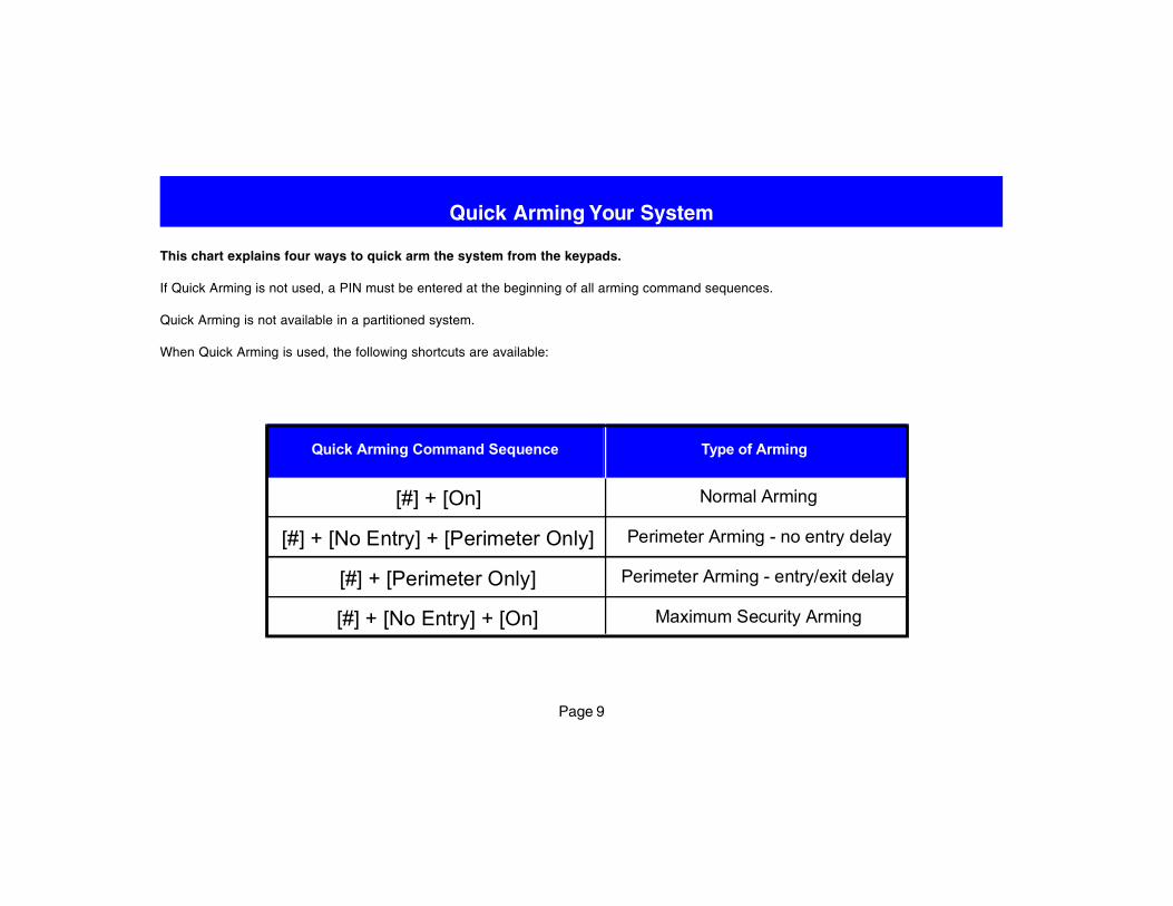
This chart explains four ways to quick arm the system from the keypads.
If Quick Arming is not used, a PIN must be entered at the beginning of all arming command sequences.
Quick Arming is not available in a partitioned system.
When Quick Arming is used, the following shortcuts are available:
Quick Arming Your System
Type of ArmingQuick Arming Command Sequence
[#] + [On]
[#] + [Perimeter Only]
[#] + [No Entry] + [Perimeter Only]
[#] + [No Entry] + [On]
Normal Arming
Perimeter Arming - entry/exit delay
Perimeter Arming - no entry delay
Maximum Security Arming
Page 10
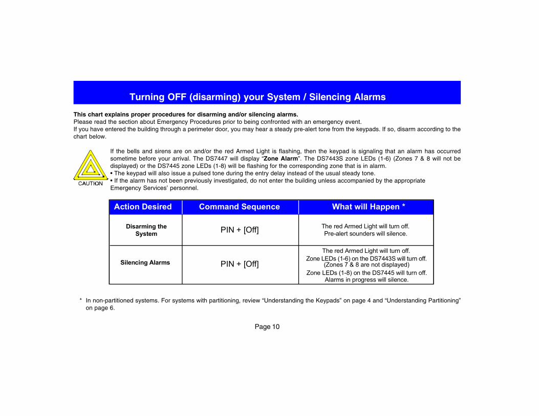
This chart explains proper procedures for disarming and/or silencing alarms.Please read the section about Emergency Procedures prior to being confronted with an emergency event.If you have entered the building through a perimeter door, you may hear a steady pre-alert tone from the keypads. If so, disarm according to thechart below.
If the bells and sirens are on and/or the red Armed Light is flashing, then the keypad is signaling that an alarm has occurredsometime before your arrival. The DS7447 will display “Zone Alarm”. The DS7443S zone LEDs (1-6) (Zones 7 & 8 will not bedisplayed) or the DS7445 zone LEDs (1-8) will be flashing for the corresponding zone that is in alarm.• The keypad will also issue a pulsed tone during the entry delay instead of the usual steady tone.• If the alarm has not been previously investigated, do not enter the building unless accompanied by the appropriateEmergency Services’ personnel.
Turning OFF (disarming) your System / Silencing Alarms
* In non-partitioned systems. For systems with partitioning, review “Understanding the Keypads” on page 4 and “Understanding Partitioning”on page 6.
Disarming theSystem
The red Armed Light will turn off.Pre-alert sounders will silence.
Action Desired Command Sequence What will Happen *
Silencing Alarms
The red Armed Light will turn off.
Zone LEDs (1-8) on the DS7445 will turn off.Alarms in progress will silence.
PIN + [Off]
PIN + [Off]Zone LEDs (1-6) on the DS7443S will turn off.
(Zones 7 & 8 are not displayed)
Page 11
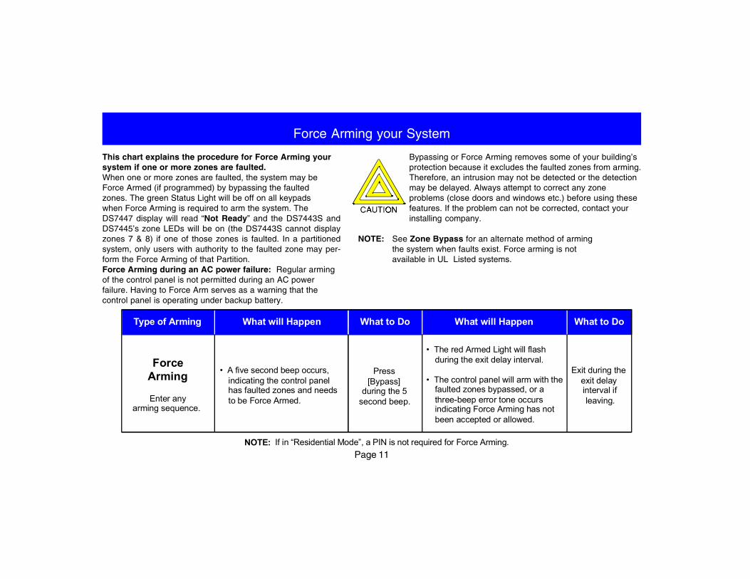
Force Arming your System
This chart explains the procedure for Force Arming yoursystem if one or more zones are faulted.When one or more zones are faulted, the system may beForce Armed (if programmed) by bypassing the faultedzones. The green Status Light will be off on all keypadswhen Force Arming is required to arm the system. TheDS7447 display will read “Not Ready” and the DS7443S andDS7445’s zone LEDs will be on (the DS7443S cannot displayzones 7 & 8) if one of those zones is faulted. In a partitionedsystem, only users with authority to the faulted zone may per-form the Force Arming of that Partition.Force Arming during an AC power failure: Regular armingof the control panel is not permitted during an AC powerfailure. Having to Force Arm serves as a warning that thecontrol panel is operating under backup battery.
Bypassing or Force Arming removes some of your building’sprotection because it excludes the faulted zones from arming.Therefore, an intrusion may not be detected or the detectionmay be delayed. Always attempt to correct any zoneproblems (close doors and windows etc.) before using thesefeatures. If the problem can not be corrected, contact yourinstalling company.
NOTE: See Zone Bypass for an alternate method of armingthe system when faults exist. Force arming is notavailable in UL Listed systems.
What will HappenWhat to DoWhat will HappenType of Arming
• A five second beep occurs,indicating the control panelhas faulted zones and needsto be Force Armed.
Exit during theexit delayinterval ifleaving.
• The red Armed Light will flashduring the exit delay interval.
• The control panel will arm with thefaulted zones bypassed, or athree-beep error tone occursindicating Force Arming has notbeen accepted or allowed.
ForceArming
Enter anyarming sequence.
What to Do
Press[Bypass]
during the 5second beep.
NOTE: If in “Residential Mode”, a PIN is not required for Force Arming.
Page 12
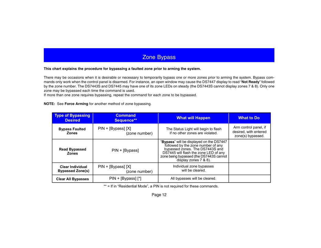
Zone Bypass
This chart explains the procedure for bypassing a faulted zone prior to arming the system.
There may be occasions when it is desirable or necessary to temporarily bypass one or more zones prior to arming the system. Bypass com-mands only work when the control panel is disarmed. For instance, an open window may cause the DS7447 display to read “Not Ready” followedby the zone number. The DS7443S and DS7445 may have one of its zone LEDs on steady (the DS7443S cannot display zones 7 & 8). Only onezone may be bypassed each time the command is used.If more than one zone requires bypassing, repeat the command for each zone to be bypassed.
NOTE: See Force Arming for another method of zone bypassing.
PIN + [Bypass] [X] (zone number)
CommandSequence** What will HappenType of Bypassing
Desired What to Do
Bypass FaultedZones
Arm control panel, ifdesired, with enteredzone(s) bypassed.
“Bypass” will be displayed on the DS7447followed by the zone number of anybypassed zones. The DS7443S and
DS7445 will flash the zone LED of anyzone being bypassed (the DS7443S cannot
display zones 7 & 8).
All bypasses will be cleared.
The Status Light will begin to flashif no other zones are violated.
Individual zone bypasses will be cleared.
Read BypassedZones
Clear IndividualBypassed Zone(s)
Clear All Bypasses
PIN + [Bypass] [X] (zone number)
PIN + [Bypass]
PIN + [Bypass] [*]
** = If in “Residential Mode”, a PIN is not required for these commands.
Page 13
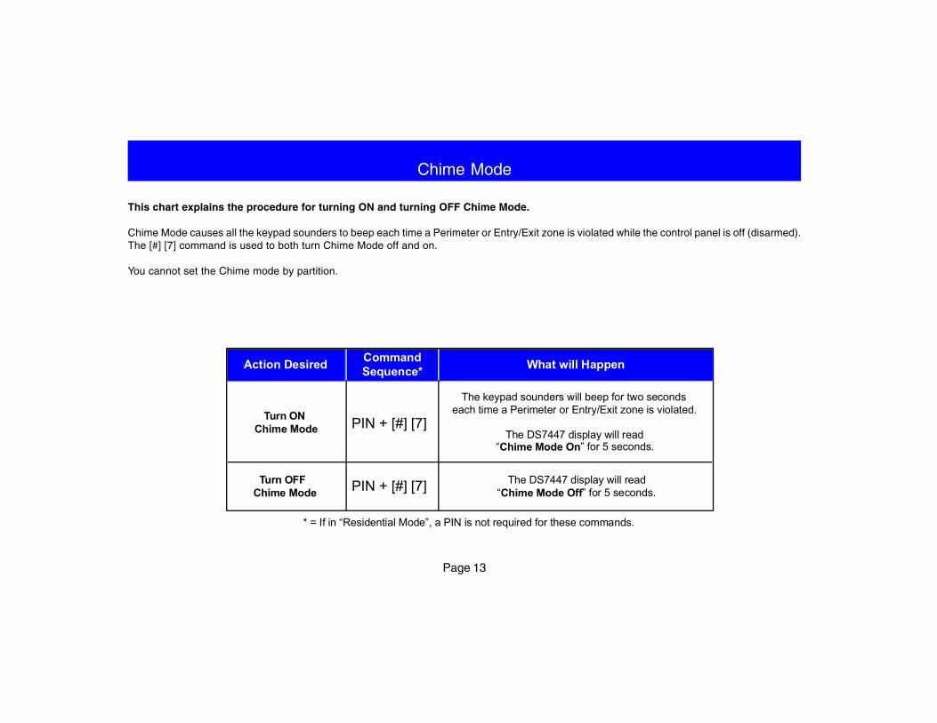
Chime Mode
This chart explains the procedure for turning ON and turning OFF Chime Mode.
Chime Mode causes all the keypad sounders to beep each time a Perimeter or Entry/Exit zone is violated while the control panel is off (disarmed).The [#] [7] command is used to both turn Chime Mode off and on.
You cannot set the Chime mode by partition.
CommandSequence*Action Desired What will Happen
Turn ONChime Mode
The keypad sounders will beep for two secondseach time a Perimeter or Entry/Exit zone is violated.
The DS7447 display will read“Chime Mode On” for 5 seconds.
Turn OFFChime Mode
The DS7447 display will read“Chime Mode Off” for 5 seconds.
PIN + [#] [7]
PIN + [#] [7]
* = If in “Residential Mode”, a PIN is not required for these commands.
Page 14
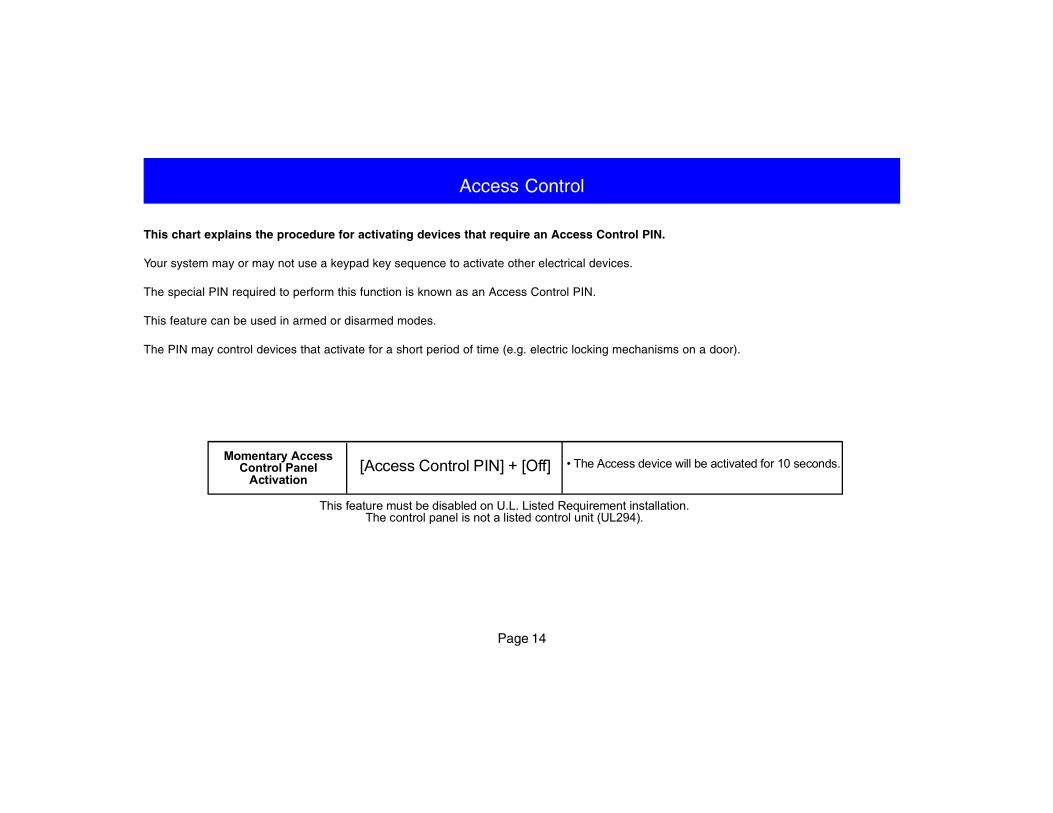
This chart explains the procedure for activating devices that require an Access Control PIN.
Your system may or may not use a keypad key sequence to activate other electrical devices.
The special PIN required to perform this function is known as an Access Control PIN.
This feature can be used in armed or disarmed modes.
The PIN may control devices that activate for a short period of time (e.g. electric locking mechanisms on a door).
Access Control
Momentary AccessControl Panel
Activation• The Access device will be activated for 10 seconds.[Access Control PIN] + [Off]
This feature must be disabled on U.L. Listed Requirement installation.The control panel is not a listed control unit (UL294).
Page 15
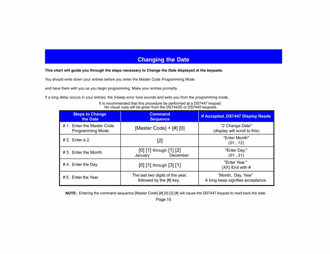
This chart will guide you through the steps necessary to Change the Date displayed at the keypads.
You should write down your entries before you enter the Master Code Programming Mode
and have them with you as you begin programming. Make your entries promptly.
If a long delay occurs in your entries, the 3-beep error tone sounds and exits you from the programming mode.
Changing the Date
# 4. Enter the Day.
# 3. Enter the Month.
# 1. Enter the Master CodeProgramming Mode.
"2 Change Date"(display will scroll to this)[Master Code] + [#] [0]
Steps to Changethe Date
CommandSequence
If Accepted, DS7447 Display Reads
# 2. Enter a 2.
# 5. Enter the Year.
“Enter Month"(01...12)
"Enter Day."(01...31)
"Enter Year."(XX) End with #
“Month, Day, Year”A long beep signifies acceptance.
[2]
[0] [1] through [1] [2] January December
[0] [1] through [3] [1]
The last two digits of the year,followed by the [#] key.
NOTE: Entering the command sequence [Master Code] [#] [0] [2] [#] will cause the DS7447 keypad to read back the date.
It is recommended that this procedure be performed at a DS7447 keypad. No visual cues will be given from the DS7443S or DS7445 keypads.
Page 16
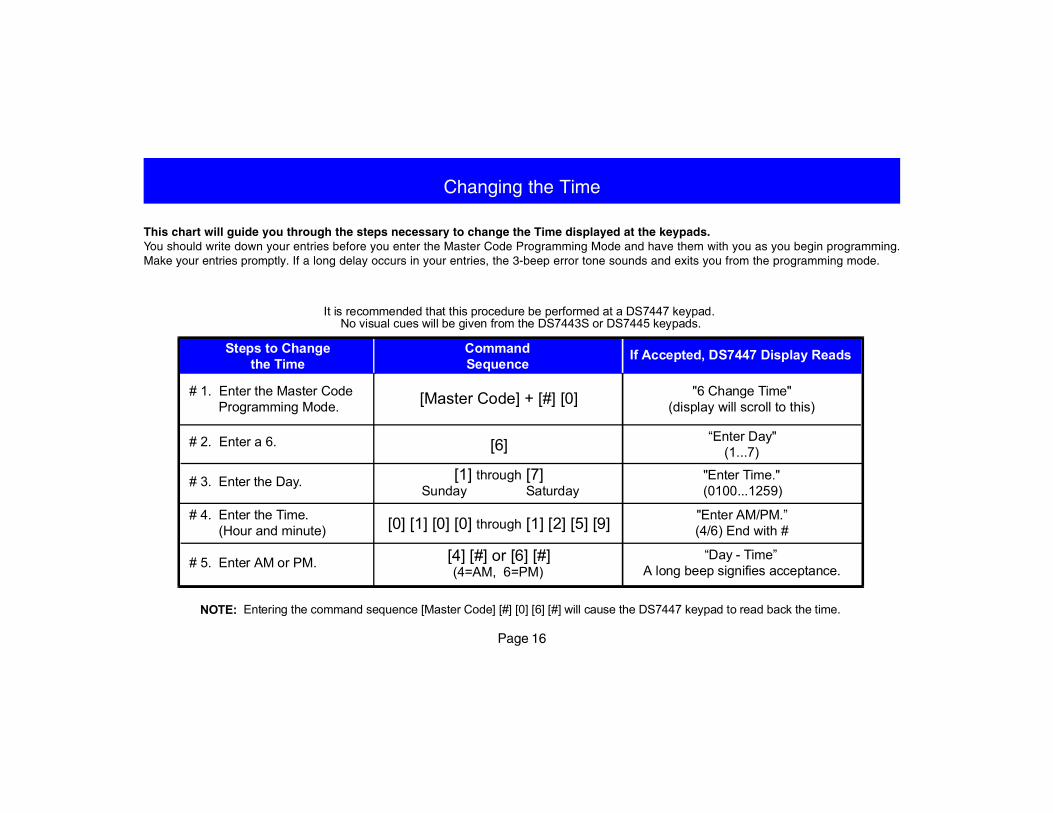
Changing the Time
This chart will guide you through the steps necessary to change the Time displayed at the keypads.You should write down your entries before you enter the Master Code Programming Mode and have them with you as you begin programming.Make your entries promptly. If a long delay occurs in your entries, the 3-beep error tone sounds and exits you from the programming mode.
[Master Code] + [#] [0]# 1. Enter the Master CodeProgramming Mode.
"6 Change Time"(display will scroll to this)
Steps to Changethe Time
If Accepted, DS7447 Display Reads
“Enter Day"(1...7)
"Enter Time."(0100...1259)
"Enter AM/PM.”(4/6) End with #
“Day - Time”A long beep signifies acceptance.
# 2. Enter a 6.
# 3. Enter the Day.
# 4. Enter the Time.(Hour and minute)
# 5. Enter AM or PM.
[6]
[1] through [7] Sunday Saturday
[0] [1] [0] [0] through [1] [2] [5] [9]
[4] [#] or [6] [#](4=AM, 6=PM)
CommandSequence
NOTE: Entering the command sequence [Master Code] [#] [0] [6] [#] will cause the DS7447 keypad to read back the time.
It is recommended that this procedure be performed at a DS7447 keypad. No visual cues will be given from the DS7443S or DS7445 keypads.
Page 17
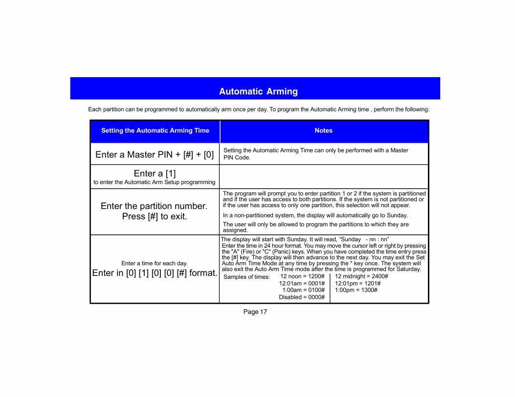
Automatic Arming
Setting the Automatic Arming Time can only be performed with a MasterPIN Code.
Notes
Each partition can be programmed to automatically arm once per day. To program the Automatic Arming time , perform the following:
Setting the Automatic Arming Time
Enter a Master PIN + [#] + [0]
Enter a [1]to enter the Automatic Arm Setup programming
Enter the partition number.Press [#] to exit.
Enter a time for each day.
Enter in [0] [1] [0] [0] [#] format.
The display will start with Sunday. It will read, “Sunday - nn : nn”Enter the time in 24 hour format. You may move the cursor left or right by pressingthe "A" (Fire) or "C" (Panic) keys. When you have completed the time entry pressthe [#] key. The display will then advance to the next day. You may exit the SetAuto Arm Time Mode at any time by pressing the * key once. The system willalso exit the Auto Arm Time mode after the time is programmed for Saturday.Samples of times: 12 noon = 1200#
12:01am = 0001#1:00am = 0100#
Disabled = 0000#
12 midnight = 2400#12:01pm = 1201#1:00pm = 1300#
The program will prompt you to enter partition 1 or 2 if the system is partitionedand if the user has access to both partitions. If the system is not partitioned orif the user has access to only one partition, this selection will not appear.
In a non-partitioned system, the display will automatically go to Sunday.The user will only be allowed to program the partitions to which they areassigned.
Page 18
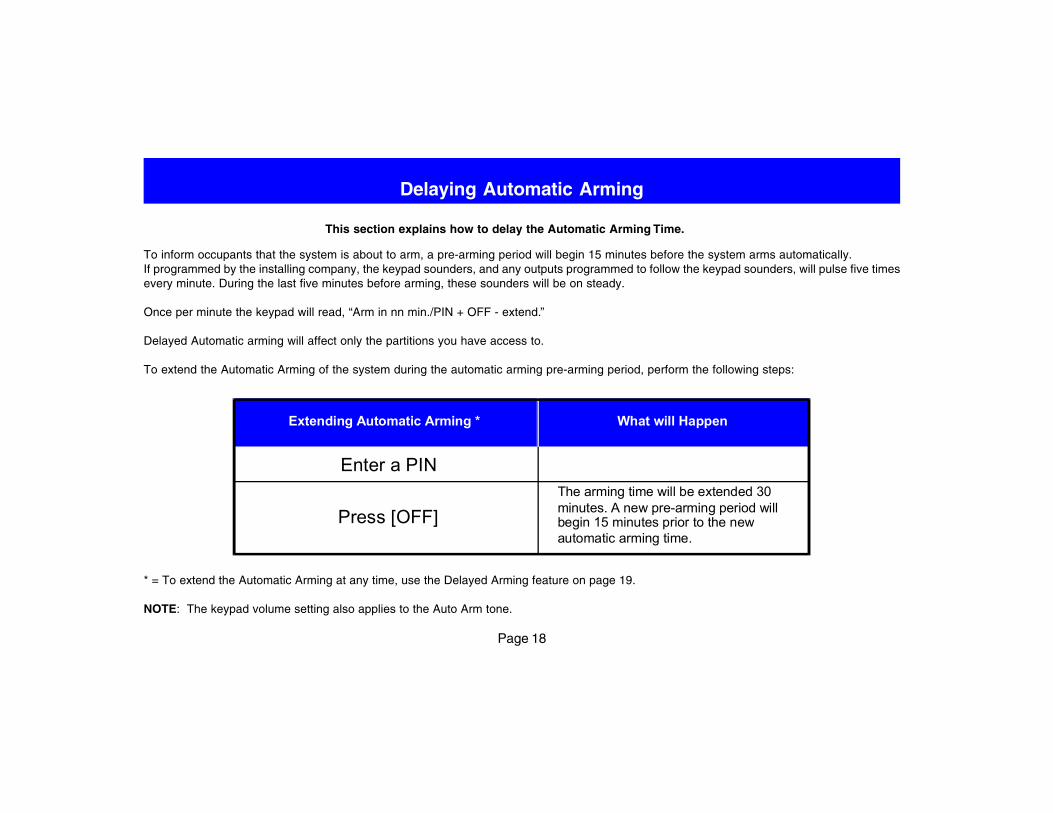
Delaying Automatic Arming
This section explains how to delay the Automatic Arming Time.
To inform occupants that the system is about to arm, a pre-arming period will begin 15 minutes before the system arms automatically.If programmed by the installing company, the keypad sounders, and any outputs programmed to follow the keypad sounders, will pulse five timesevery minute. During the last five minutes before arming, these sounders will be on steady.
Once per minute the keypad will read, “Arm in nn min./PIN + OFF - extend.”
Delayed Automatic arming will affect only the partitions you have access to.
To extend the Automatic Arming of the system during the automatic arming pre-arming period, perform the following steps:
What will HappenExtending Automatic Arming *
Enter a PIN
Press [OFF]The arming time will be extended 30minutes. A new pre-arming period willbegin 15 minutes prior to the newautomatic arming time.
* = To extend the Automatic Arming at any time, use the Delayed Arming feature on page 19.
NOTE: The keypad volume setting also applies to the Auto Arm tone.
Page 19
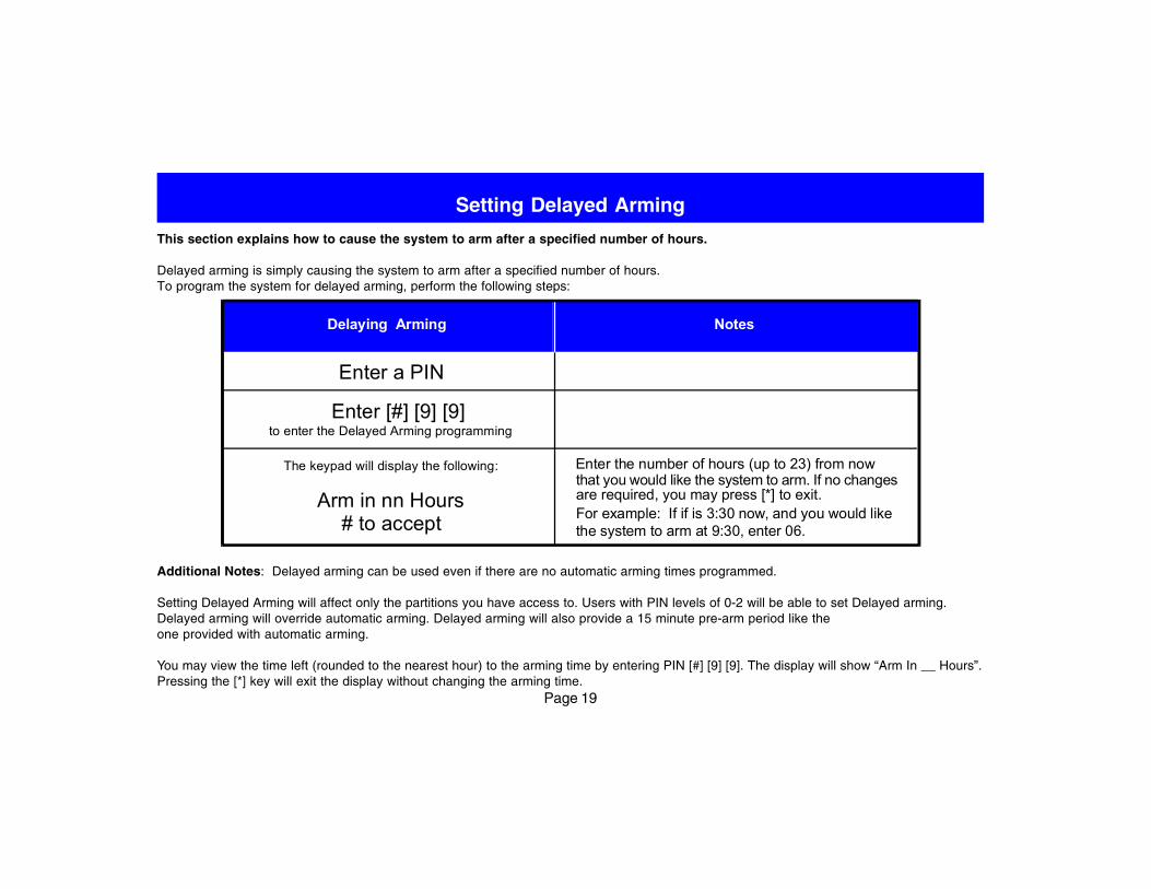
Setting Delayed Arming
This section explains how to cause the system to arm after a specified number of hours.
Delayed arming is simply causing the system to arm after a specified number of hours.To program the system for delayed arming, perform the following steps:
NotesDelaying Arming
Enter a PIN
Enter [#] [9] [9]to enter the Delayed Arming programming
Enter the number of hours (up to 23) from nowthat you would like the system to arm. If no changesare required, you may press [*] to exit.For example: If if is 3:30 now, and you would likethe system to arm at 9:30, enter 06.
The keypad will display the following:
Arm in nn Hours# to accept
Additional Notes: Delayed arming can be used even if there are no automatic arming times programmed.
Setting Delayed Arming will affect only the partitions you have access to. Users with PIN levels of 0-2 will be able to set Delayed arming.Delayed arming will override automatic arming. Delayed arming will also provide a 15 minute pre-arm period like theone provided with automatic arming.
You may view the time left (rounded to the nearest hour) to the arming time by entering PIN [#] [9] [9]. The display will show “Arm In __ Hours”.Pressing the [*] key will exit the display without changing the arming time.
Page 20
Identifying Alarm SoundsYour alarm system may be programmed for a steady alarmsound or a pulsed alarm sound. It is important to learn thedifference between a fire alarm sound and an intrusion alarmsound before you are confronted with an actual emergency.
Silencing AlarmsAll alarms can be silenced with any PIN that has disarmprivileges. Entering your PIN + [Off] will silence the alarmand turn off (disarm) the control.
A Cautionary NoteHow you respond to an alarm will depend, mostly, on thetype and time of the alarm. You should seek the advice ofyour installing company as they install your system, not later(e.g. after an alarm) to develop a response plan.
Above all else, common sense should prevail.If there is any threat or hint of danger to yourself or others onthe premises, such as in the event of a fire alarm, everyoneshould be instructed to leave the premises immediately. Donot enter the premises unless accompanied by theappropriate Emergency Services’ personnel, or after theyhave given the OK to enter.
Emergency Procedures
Caution When Entering A BuildingIf the bells and sirens are on and/or the red Armed Light isflashing with the DS7447 display reading “Zone Alarm” orthe DS7445 having its zone LEDs 1-8 flashing, then thekeypad is signaling that an alarm has occurred. The keypadwill also issue a pulsed tone during the entry delay instead ofthe usual steady tone.
If the alarm has not been previously investigated, do notenter the building unless accompanied by theappropriate Emergency Services’ personnel.
Fire AlarmsFire Alarms are silenced using the same procedure asintrusion alarms: a PIN (with disarm privileges) + the [Off]key.
The Fire Alarm system is not reset until alarms at smokedetectors are cleared by using the [System Reset] command.The Fire Alarm system will not be functional until thisprocedure has been followed. See Fire Reset on page 23.
Page 21
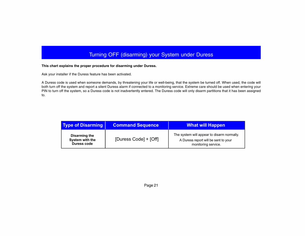
Turning OFF (disarming) your System under Duress
This chart explains the proper procedure for disarming under Duress.
Ask your installer if the Duress feature has been activated.
A Duress code is used when someone demands, by threatening your life or well-being, that the system be turned off. When used, the code willboth turn off the system and report a silent Duress alarm if connected to a monitoring service. Extreme care should be used when entering yourPIN to turn off the system, so a Duress code is not inadvertently entered. The Duress code will only disarm partitions that it has been assignedto.
Disarming theSystem with the
Duress code
The system will appear to disarm normally.A Duress report will be sent to your
monitoring service.
Type of Disarming Command Sequence What will Happen
[Duress Code] + [Off]
Page 22
Emergency Keypad Alarms / Silencing Alarms
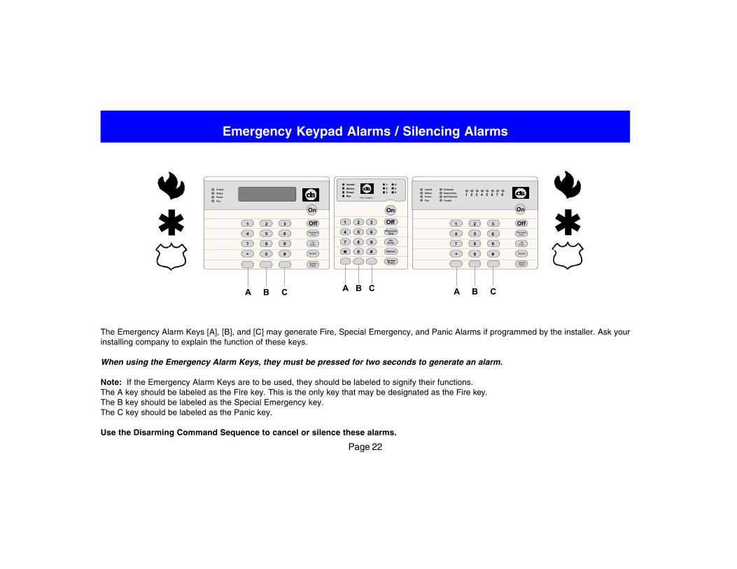
The Emergency Alarm Keys [A], [B], and [C] may generate Fire, Special Emergency, and Panic Alarms if programmed by the installer. Ask yourinstalling company to explain the function of these keys.
When using the Emergency Alarm Keys, they must be pressed for two seconds to generate an alarm.
Note: If the Emergency Alarm Keys are to be used, they should be labeled to signify their functions.The A key should be labeled as the Fire key. This is the only key that may be designated as the Fire key.The B key should be labeled as the Special Emergency key.The C key should be labeled as the Panic key.
Use the Disarming Command Sequence to cancel or silence these alarms.
Armed
Status
Power
Fire
Perimeter
Supervisory
Bell Silenced
Trouble
1 2 3 4 5 6 7 8
1 2 3
4 5 6
7 8 9
0* #
On
NoEntry
SystemReset
Bypass
OnlyPerimeter
Off
Armed
Status
Power
Fire
1 2 3
4 5 6
7 8 9
0* #
On
NoEntry
SystemReset
Bypass
OnlyPerimeter
Off
On
NoEntry
SystemReset
Bypass
PerimeterOnly
Off321
654
987
#0*
Fire
Armed
Status
1
23
4
56Power
TEST WEEKLY
A B C A B CA B C
Page 23
Fire Reset / Fire Trouble
Fire Reset
During a fire alarm, exit the premises immediately. When you have de-termined there is no fire, it is recommended that you silence the bells/sirens before you initiate the [System Reset] command.
Before the [System Reset] command is used, deter-mine which smoke detector has alarmed so the in-stalling company may verify its operation.
A PIN followed by the [System Reset] key will reset anysmoke detectors after a fire alarm has occurred.
PIN + [System Reset]
NOTE: To use the System Reset command sequence, yourPIN must have disarm privileges.
The System Reset command will perform a fire reset, willperform a battery test, and will clear all system troubles.
Fire Trouble
A Fire Trouble display signifies a problem with the fire system, such asa break in the wiring that monitors smoke detectors.
A Fire Trouble will be indicated by a short beep from the keypad sound-ers every 10 seconds. The DS7447 keypad will display “Fire Trouble”followed by the zones in a trouble condition.
The DS7443S and DS7445 keypads will turn the Fire and Trouble Lightson steady and will light the corresponding zone LEDs.
Notify your installing company immediately if the Fire Trouble messageis displayed.
The Fire Trouble beep can be silenced with any PIN followed by the[Off] key. After problems have been remedied, a PIN followed by[System Reset] should be entered to clear the “Fire Trouble” display.
Page 24
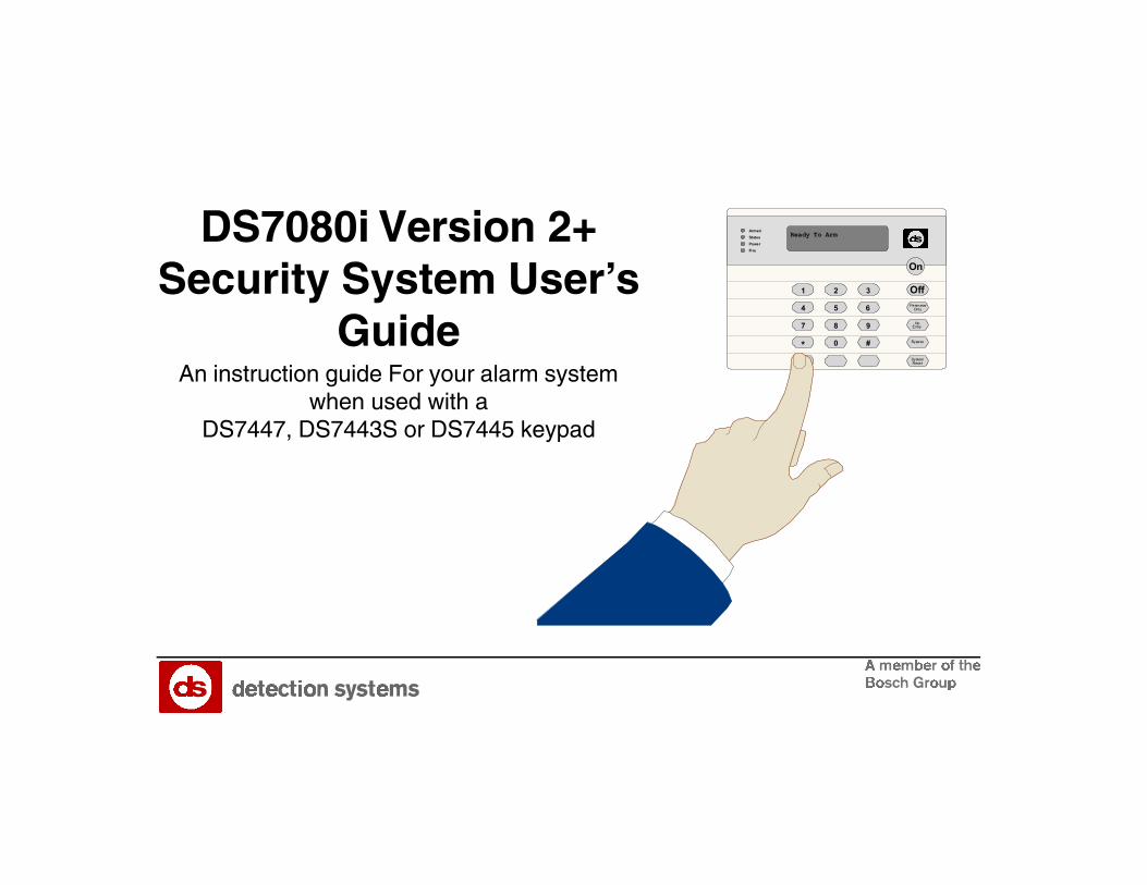
Fire Safety
This fire alarm system can provide early warning of a developing fire.Such a system, however, does not ensure protection against propertydamage or loss of life resulting from a fire. Any fire alarm system mayfail to warn for any number of reasons (e.g. smoke not reaching a detectorthat is behind a closed door).
When considering detectors for residential applications, refer to NFPAStandard 72, “The National Fire Alarm Code.” This standard is availableat a nominal cost from: The National Fire Protection Association,Batterymarch Park, Quincy, MA 02269.
If Installed in Family Residences
Adherence to the NFPA Standard 72 can lead to reasonable fire safetywhen the following items are practiced:
• Minimize hazards: Avoid the three traditional fire killers:smoking in bed, leaving children home alone, and cleaningwith flammable liquids.
• Providing a fire warning system: Most fire deaths occur in thehome, the majority, during sleeping hours. The minimum level ofprotection requires smoke detectors to be installed outside of eachseparate sleeping area and on each additional story of the dwelling.
For added early warning protection, it is recommended that detectorsbe installed in all separated areas including the basement, bedrooms,dining room, utility room, furnace room, and hallways.
Having and Practicing an Escape Plan
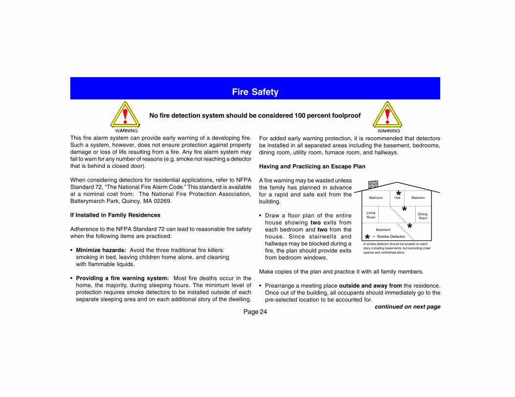
A fire warning may be wasted unlessthe family has planned in advancefor a rapid and safe exit from thebuilding.
• Draw a floor plan of the entirehouse showing two exits fromeach bedroom and two from thehouse. Since stairwells andhallways may be blocked during afire, the plan should provide exitsfrom bedroom windows.
Make copies of the plan and practice it with all family members.
• Prearrange a meeting place outside and away from the residence.Once out of the building, all occupants should immediately go to thepre-selected location to be accounted for.
continued on next page
No fire detection system should be considered 100 percent foolproof
*story including basements, but excluding crawlA smoke detector should be located on each
spaces and unfinished attics.
Bedroom BedroomHall
LivingRoom
DiningRoom
Basement
**
* = Smoke Detector
Page 25
Fire Safety (continued)
• Provide a barricade between family members and fire, smoke, andtoxic gases (e.g. close all bedroom doors before retiring).
• Children should be instructed on opening their bedroom windowsand exiting safely from the building. If exiting is not possible, theyshould be taught to stay at the open window and shout for help untilit arrives.
• In the event of a fire alarm after retiring, wake the children by shoutingto them from behind your closed door. Tell them to keep their bedroomdoors closed.
• If the top of your bedroom door is uncomfortably hot, do notopen it. There is most likely fire, intolerable heat, or smoke on theother side. Shout to all family members to keep their bedroom doorsclosed and to exit the building via alternate routes.
• If the top of the door is not uncomfortably hot, brace the bottom ofthe door with your foot, and the top with one hand, then open thedoor about one inch. Be prepared to slam the door shut if there isany pressure against the door or if any hot air rushes in.
• If there is no evidence of excessive heat or pressure, leave theroom and close the door behind you. Shout appropriateinstructions to all family members and immediately leave the buildingvia the pre-planned routes. If heavy smoke is present, drop to yourhands and knees, or crawl to remain below the smoke level.
Installation Considerations
Proper location of detection devices is one of the most criticalfactors in a fire alarm system.
The following are some general considerations:
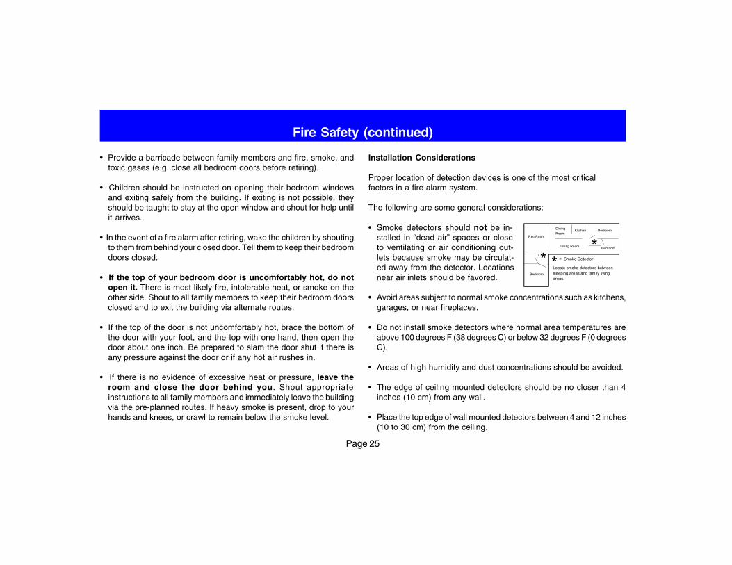
• Smoke detectors should not be in-stalled in “dead air” spaces or closeto ventilating or air conditioning out-lets because smoke may be circulat-ed away from the detector. Locationsnear air inlets should be favored.
• Avoid areas subject to normal smoke concentrations such as kitchens,garages, or near fireplaces.
• Do not install smoke detectors where normal area temperatures areabove 100 degrees F (38 degrees C) or below 32 degrees F (0 degreesC).
• Areas of high humidity and dust concentrations should be avoided.
• The edge of ceiling mounted detectors should be no closer than 4inches (10 cm) from any wall.
• Place the top edge of wall mounted detectors between 4 and 12 inches(10 to 30 cm) from the ceiling.
Rec Room
DiningRoom
Kitchen Bedroom
BedroomLiving Room
Bedroom
Locate smoke detectors betweensleeping areas and family livingareas.
* = Smoke Detector**
Page 26
Personal Identification Numbers
General Information
When programing Personal Identification Numbers, it is helpful to knowthe following terms:
• PIN: Personal Identification Number. This is the 4 or 6 digit codeusers enter at the keypad to gain access to the system. A PIN maybe assigned to each User Number 001 - 015.
• Partition (Area): This is the area the User has authority in. You mayselect Partition (Area) 1, 2 or both.
• User Number: This is the number that identifies each person usingthe system. There are 15 possible User Numbers (001 - 015).
• Authority Level: This number determines which functions each userwill be able to perform (see page 27).
Your system has the capacity to assign up to 15 PINs. The length ofthe PINs will be fixed at 4 or 6 digits. You cannot have both 4 and 6 digitPINs in the same system. If you wish to change the PIN length, it willbe necessary to have your installing company make the change. If
changed, all new PINs will need to be assigned. Each User numbermay have only one PIN assigned to it. Attempting to assign the samePIN to multiple User Numbers will result in a 3 beep entry error tone,and the entry will not be made.
User Number 001 is designated as a Master Code. It can be used toadd, delete or change other PINs.
User Number 001 is shipped from the factory with the sequence of123456. This code should be changed to one of your personalpreference, and must be programmed as a Master Code. PINs shouldnever be programmed with common sequences such as 1111 or 2468because they are easily violated.
Removing a PIN
To remove a PIN: enter a [Master Code] [#] [0] [0], the User Number ofthe PIN to be canceled, and then [#] again.
User Number 001 can not be canceled in this manner.
continued on next page
Page 27
Personal Identification Numbers (continued)
PIN Authority Levels
0 = Master: Can enter all commands, add or change PINs, changetime and date, bypass, arm, set autoarm, disarm, perform systemtests, system reset, and view history. PIN 001 must be a mastercode and must have authority 0. Any or all PINs may be mastercodes.
1 = Unlimited: Can enter all commands, bypass, arm, disarm, systemreset, and perform system tests. Can not change PINs.
2 = General: Can bypass, arm and disarm. Can not change PINs,system reset, or enter the [#] [7] or [#] [8] functions.
3 = Arm Only: Can arm the system with [#] [On] arming only. Can notperform any other functions including disarming.
4 = Temporary: Valid only for a limited time. Can arm and disarm thesystem, but can not perform any other functions. This code willautomatically be deleted after 15 days if you have not already doneso.
The 15 day clock is reset to 15 days each time a TemporaryPIN is assigned. All Temporary PINs expire at the sametime.
5 = Duress: When the system is disarmed using a duress code, asilent report is sent to the central station. Duress codes are intendedto be used when the user is forced to disarm the system.
6 = Access: When a PIN with Access Code authority is entered, anyoutput programmed for Access Output (e.g. door strikes) will pulseon for 10 seconds (works when the system is armed or disarmed).
continued on next page
Page 28
Personal Identification Numbers (continued)
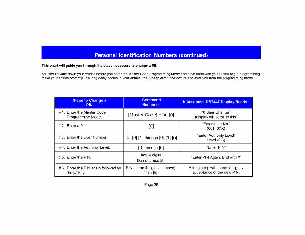
This chart will guide you through the steps necessary to change a PIN.
You should write down your entries before you enter the Master Code Programming Mode and have them with you as you begin programming.Make your entries promptly. If a long delay occurs in your entries, the 3-beep error tone occurs and exits you from the programming mode.
# 1. Enter the Master CodeProgramming Mode.
“0 User Change”(display will scroll to this)[Master Code] + [#] [0]
Steps to Change aPIN
CommandSequence
If Accepted, DS7447 Display Reads
# 2. Enter a 0. [0] “Enter User No.”(001..0XX)
# 3. Enter the User Number. [0] [0] [1] through [0] [1] [5] “Enter Authority Level”Level (0-6)
# 4. Enter the Authority Level. [0] through [6] “Enter PIN”
# 5. Enter the PIN. Any 4 digits.Do not press [#].
# 6. Enter the PIN again followed bythe [#] key.
PIN (same 4 digits as above),then [#].
A long beep will sound to signifyacceptance of the new PIN.
“Enter PIN Again. End with #”
Page 29
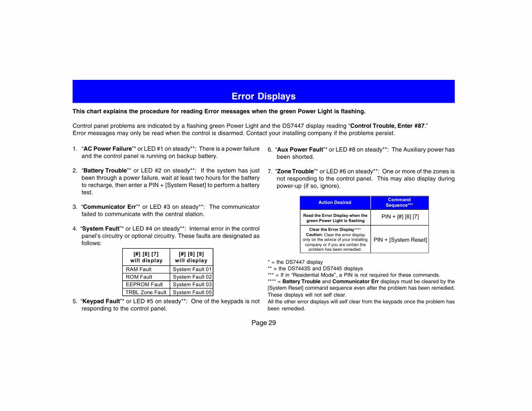
Error DisplaysThis chart explains the procedure for reading Error messages when the green Power Light is flashing.
Control panel problems are indicated by a flashing green Power Light and the DS7447 display reading “Control Trouble, Enter #87.”Error messages may only be read when the control is disarmed. Contact your installing company if the problems persist.
1. “AC Power Failure”* or LED #1 on steady**: There is a power failureand the control panel is running on backup battery.
2. “Battery Trouble”* or LED #2 on steady**: If the system has justbeen through a power failure, wait at least two hours for the batteryto recharge, then enter a PIN + [System Reset] to perform a batterytest.
3. “Communicator Err”* or LED #3 on steady**: The communicatorfailed to communicate with the central station.
4. “System Fault”* or LED #4 on steady**: Internal error in the controlpanel’s circuitry or optional circuitry. These faults are designated asfollows:
5. “Keypad Fault”* or LED #5 on steady**: One of the keypads is notresponding to the control panel.
6. “Aux Power Fault”* or LED #8 on steady**: The Auxiliary power hasbeen shorted.
7. “Zone Trouble”* or LED #6 on steady**: One or more of the zones isnot responding to the control panel. This may also display duringpower-up (if so, ignore).
* = the DS7447 display** = the DS7443S and DS7445 displays*** = If in “Residential Mode”, a PIN is not required for these commands.**** = Battery Trouble and Communicator Err displays must be cleared by the[System Reset] command sequence even after the problem has been remedied.These displays will not self clear.All the other error displays will self clear from the keypads once the problem hasbeen remedied.
CommandSequence***Action Desired
Read the Error Display when thegreen Power Light is flashing
Clear the Error Display****Caution: Clear the error display
only on the advice of your installingcompany or if you are certain the
problem has been remedied.
PIN + [#] [8] [7]
PIN + [System Reset]
[#] [8] [9]will display
[#] [8] [7]will display
System Fault 01System Fault 02System Fault 03System Fault 05
RAM FaultROM FaultEEPROM FaultTRBL Zone Fault
Page 30
Testing Your System
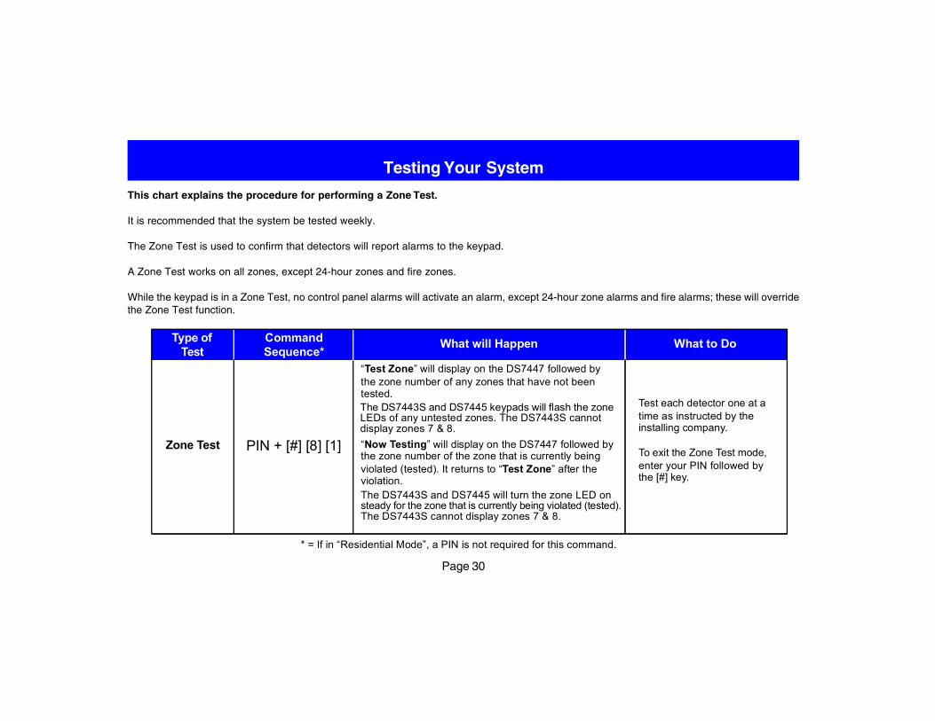
This chart explains the procedure for performing a Zone Test.
It is recommended that the system be tested weekly.
The Zone Test is used to confirm that detectors will report alarms to the keypad.
A Zone Test works on all zones, except 24-hour zones and fire zones.
While the keypad is in a Zone Test, no control panel alarms will activate an alarm, except 24-hour zone alarms and fire alarms; these will overridethe Zone Test function.
Test each detector one at atime as instructed by theinstalling company.
To exit the Zone Test mode,enter your PIN followed bythe [#] key.
Zone Test
Type ofTest
What will HappenCommandSequence*
What to Do
PIN + [#] [8] [1]
The DS7443S and DS7445 keypads will flash the zoneLEDs of any untested zones. The DS7443S cannotdisplay zones 7 & 8.
The DS7443S and DS7445 will turn the zone LED onsteady for the zone that is currently being violated (tested).The DS7443S cannot display zones 7 & 8.
* = If in “Residential Mode”, a PIN is not required for this command.
“Test Zone” will display on the DS7447 followed bythe zone number of any zones that have not beentested.
“Now Testing” will display on the DS7447 followed bythe zone number of the zone that is currently beingviolated (tested). It returns to “Test Zone” after theviolation.
Page 31
Testing Your System (continued)
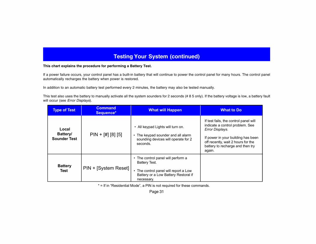
This chart explains the procedure for performing a Battery Test.
If a power failure occurs, your control panel has a built-in battery that will continue to power the control panel for many hours. The control panelautomatically recharges the battery when power is restored.
In addition to an automatic battery test performed every 2 minutes, the battery may also be tested manually.
This test also uses the battery to manually activate all the system sounders for 2 seconds (# 8 5 only). If the battery voltage is low, a battery faultwill occur (see Error Displays).
PIN + [System Reset]
CommandSequence*
Type of Test What to DoWhat will Happen
LocalBattery/
Sounder Test
• All keypad Lights will turn on.
• The keypad sounder and all alarmsounding devices will operate for 2seconds.
If test fails, the control panel willindicate a control problem. SeeError Displays.
If power in your building has beenoff recently, wait 2 hours for thebattery to recharge and then tryagain.
BatteryTest
• The control panel will perform aBattery Test.
• The control panel will report a LowBattery or a Low Battery Restoral ifnecessary.
PIN + [#] [8] [5]
* = If in “Residential Mode”, a PIN is not required for these commands.
Page 32
Testing Your System (continued)
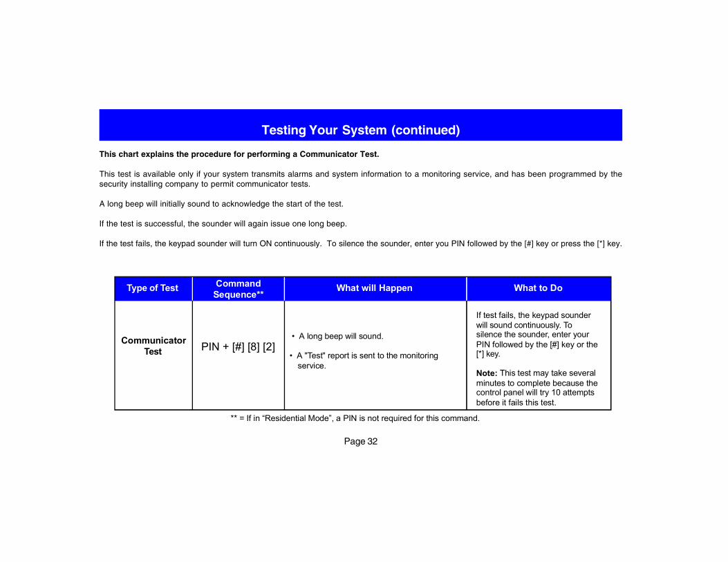
This chart explains the procedure for performing a Communicator Test.
This test is available only if your system transmits alarms and system information to a monitoring service, and has been programmed by thesecurity installing company to permit communicator tests.
A long beep will initially sound to acknowledge the start of the test.
If the test is successful, the sounder will again issue one long beep.
If the test fails, the keypad sounder will turn ON continuously. To silence the sounder, enter you PIN followed by the [#] key or press the [*] key.
Type of Test CommandSequence**
What to Do
CommunicatorTest
• A long beep will sound.
• A "Test" report is sent to the monitoringservice.
If test fails, the keypad sounderwill sound continuously. Tosilence the sounder, enter yourPIN followed by the [#] key or the[*] key.
Note: This test may take severalminutes to complete because thecontrol panel will try 10 attemptsbefore it fails this test.
What will Happen
PIN + [#] [8] [2]
** = If in “Residential Mode”, a PIN is not required for this command.
Page 33
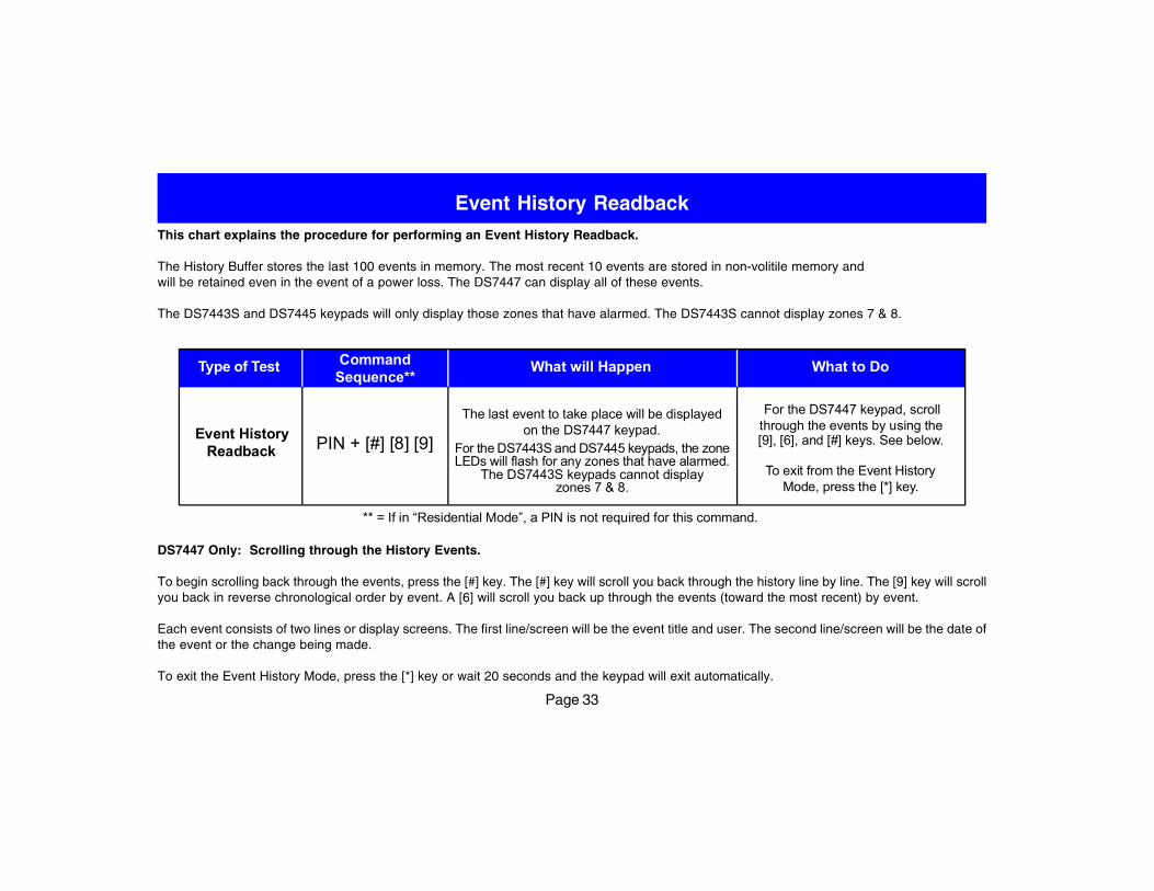
Event History ReadbackThis chart explains the procedure for performing an Event History Readback.
The History Buffer stores the last 100 events in memory. The most recent 10 events are stored in non-volitile memory andwill be retained even in the event of a power loss. The DS7447 can display all of these events.
The DS7443S and DS7445 keypads will only display those zones that have alarmed. The DS7443S cannot display zones 7 & 8.
What to DoType of Test CommandSequence**
Event HistoryReadback
The last event to take place will be displayedon the DS7447 keypad.
For the DS7443S and DS7445 keypads, the zoneLEDs will flash for any zones that have alarmed.
The DS7443S keypads cannot displayzones 7 & 8.
For the DS7447 keypad, scrollthrough the events by using the[9], [6], and [#] keys. See below.
To exit from the Event HistoryMode, press the [*] key.
What will Happen
PIN + [#] [8] [9]
** = If in “Residential Mode”, a PIN is not required for this command.
DS7447 Only: Scrolling through the History Events.
To begin scrolling back through the events, press the [#] key. The [#] key will scroll you back through the history line by line. The [9] key will scrollyou back in reverse chronological order by event. A [6] will scroll you back up through the events (toward the most recent) by event.
Each event consists of two lines or display screens. The first line/screen will be the event title and user. The second line/screen will be the date ofthe event or the change being made.
To exit the Event History Mode, press the [*] key or wait 20 seconds and the keypad will exit automatically.
Page 34
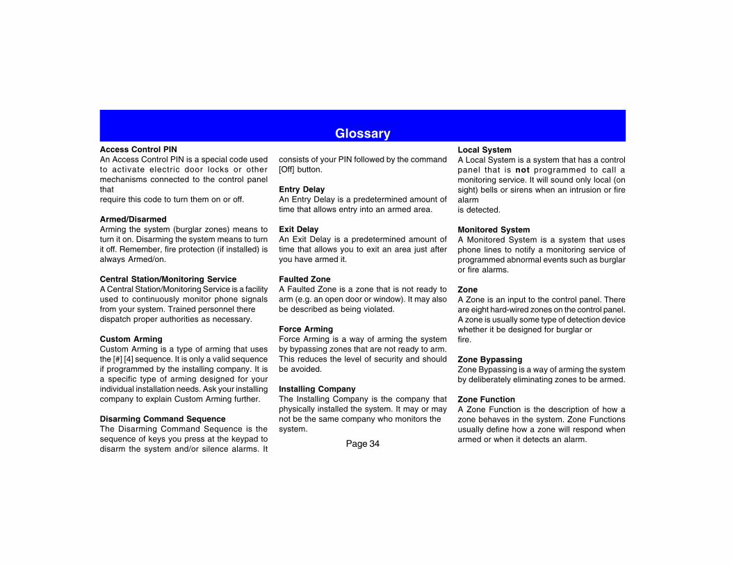
GlossaryAccess Control PINAn Access Control PIN is a special code usedto activate electric door locks or othermechanisms connected to the control panelthatrequire this code to turn them on or off.
Armed/DisarmedArming the system (burglar zones) means toturn it on. Disarming the system means to turnit off. Remember, fire protection (if installed) isalways Armed/on.
Central Station/Monitoring ServiceA Central Station/Monitoring Service is a facilityused to continuously monitor phone signalsfrom your system. Trained personnel theredispatch proper authorities as necessary.
Custom ArmingCustom Arming is a type of arming that usesthe [#] [4] sequence. It is only a valid sequenceif programmed by the installing company. It isa specific type of arming designed for yourindividual installation needs. Ask your installingcompany to explain Custom Arming further.
Disarming Command SequenceThe Disarming Command Sequence is thesequence of keys you press at the keypad todisarm the system and/or silence alarms. It
consists of your PIN followed by the command[Off] button.
Entry DelayAn Entry Delay is a predetermined amount oftime that allows entry into an armed area.
Exit DelayAn Exit Delay is a predetermined amount oftime that allows you to exit an area just afteryou have armed it.
Faulted ZoneA Faulted Zone is a zone that is not ready toarm (e.g. an open door or window). It may alsobe described as being violated.
Force ArmingForce Arming is a way of arming the systemby bypassing zones that are not ready to arm.This reduces the level of security and shouldbe avoided.
Installing CompanyThe Installing Company is the company thatphysically installed the system. It may or maynot be the same company who monitors thesystem.
Local SystemA Local System is a system that has a controlpanel that is not programmed to call amonitoring service. It will sound only local (onsight) bells or sirens when an intrusion or firealarmis detected.
Monitored SystemA Monitored System is a system that usesphone lines to notify a monitoring service ofprogrammed abnormal events such as burglaror fire alarms.
ZoneA Zone is an input to the control panel. Thereare eight hard-wired zones on the control panel.A zone is usually some type of detection devicewhether it be designed for burglar orfire.
Zone BypassingZone Bypassing is a way of arming the systemby deliberately eliminating zones to be armed.
Zone FunctionA Zone Function is the description of how azone behaves in the system. Zone Functionsusually define how a zone will respond whenarmed or when it detects an alarm.
Page 35
Quick Reference Guide
This system should be tested weekly to ensure it is functioning properly. If problems are detected in testing or changes are noticed in normaloperation, call your installing company for service. The manufacturer recommends replacing the system battery every 3 to 5 years.
Monitoring Service Phone Number. ______________________________
Monitoring Service System Number. _____________________________
Installing Company Phone Number: _____________________________
Protection
Zone 1 _______________________
Zone 2 _______________________
Zone 3 _______________________
Zone 4 _______________________
Zone 5 _______________________
Zone 6 _______________________
Zone 7 _______________________
Zone 8 _______________________
Page 36
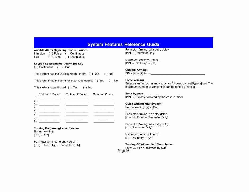
System Features Reference GuideAudible Alarm Signaling Device SoundsIntrusion ( ) Pulse ( ) ContinuousFire ( ) Pulse ( ) Continuous
Keypad Supplemental Alarm [B] Key( ) Continuous ( ) Silent
This system has the Duress Alarm feature. ( ) Yes ( ) No
This system has the communicator test feature. ( ) Yes ( ) No
This system is partitioned. ( ) Yes ( ) No
Partition 1 Zones Partition 2 Zones Common Zones1- _____________ ______________ _____________2- _____________ ______________ _____________3- _____________ ______________ _____________4- _____________ ______________ _____________5- _____________ ______________ _____________6- _____________ ______________ _____________7- _____________ ______________ _____________8- _____________ ______________ _____________
Turning On (arming) Your SystemNormal Arming:[PIN] + [On]
Perimeter Arming, no entry delay:[PIN] + [No Entry] + [Perimeter Only]
Perimeter Arming, with entry delay:[PIN] + [Perimeter Only]
Maximum Security Arming:[PIN] + [No Entry] + [On]
Custom ArmingPIN + [#] + [4] Arms __________________________________
Force ArmingEnter an arming command sequence followed by the [Bypass] key. Themaximum number of zones that can be forced armed is _____
Zone Bypass[PIN] + [Bypass] followed by the Zone number.
Quick Arming Your SystemNormal Arming: [#] + [On]
Perimeter Arming, no entry delay:[#] + [No Entry] + [Perimeter Only]
Perimeter Arming, with entry delay:[#] + [Perimeter Only]
Maximum Security Arming:[#] + [No Entry] + [On]
Turning Off (disarming) Your SystemEnter your [PIN] followed by [Off]
Page 37
System Features Reference Guide (continued)
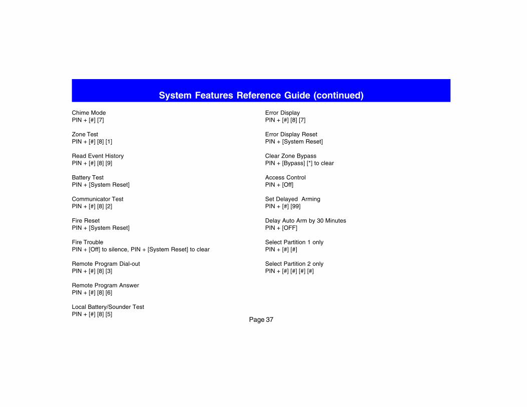
Chime ModePIN + [#] [7]
Zone TestPIN + [#] [8] [1]
Read Event HistoryPIN + [#] [8] [9]
Battery TestPIN + [System Reset]
Communicator TestPIN + [#] [8] [2]
Fire ResetPIN + [System Reset]
Fire TroublePIN + [Off] to silence, PIN + [System Reset] to clear
Remote Program Dial-outPIN + [#] [8] [3]
Remote Program AnswerPIN + [#] [8] [6]
Local Battery/Sounder TestPIN + [#] [8] [5]
Error DisplayPIN + [#] [8] [7]
Error Display ResetPIN + [System Reset]
Clear Zone BypassPIN + [Bypass] [*] to clear
Access ControlPIN + [Off]
Set Delayed ArmingPIN + [#] [99]
Delay Auto Arm by 30 MinutesPIN + [OFF]
Select Partition 1 onlyPIN + [#] [#]
Select Partition 2 onlyPIN + [#] [#] [#] [#]
Page 38
Index
AAC Power Failure 29AC power failure 11Access Control 14Access Control PIN 34Access PIN 27Arm Only PIN 27Armed 34Authority Level 26Automatic Arming 17Aux Power Fault 29
BBattery Test 31Battery Trouble 29bypass 12
CCentral Station 34change a PIN 28Change the Date 15change the time 16Chime Mode 13Communicator Err 29Communicator Test 32Control Panel 2Control Station 2Control Trouble 29Custom Arming 6, 34
DDate 15delay auto arm 18Delayed Arming 19Delayed Automatic Arming 18
Disarmed 34disarming 10Disarming Command Sequence 34DS7445 4DS7447 4Duress 21Duress PIN 27
EEntry Delay 34Event History 33Exit Delay 34
FFaulted Zone 34Fire Alarms 20Fire key 22Fire Reset 23Fire Safety 24Fire Trouble 23Force Arming 11, 34
GGeneral PIN 27
HHistory Buffer 33History Readback 33
IInstalling Company 34
KKeypad Fault 29
Lline seizure 2Local System 34
MMaster PIN 27Monitored System 34Monitoring Service 34
NNot Ready 7
PPanic key 22Partition 26Partitioned 6Personal Identification Numbers 26PIN 26PIN Authority Levels 27PIN Master 27Protected Zones 2
Qquick arm 9
RReady to Arm 7
SSetting Delayed Arming 19Silencing Alarms 20Special Emergency key 22System Fault 29
TTemporary PIN 27Time 16
UUnlimited PIN 27User Number 26
ZZone 34Zone Bypassing 34Zone Function 34Zone Test 30Zone Trouble 29

Page 39
Notes
Detection Systems, Inc., 130 Perinton Parkway,Fairport, New York, USA 14450-9199(585) 223-4060 • (888) 289-0096 • Fax: (585) 223-9180
Copyright © 2001 Detection Systems, Inc.DS7080i Version 2+ Users GuideP/N: 34858C 9/01 Page 40