Embed Size (px)
Citation preview
- - Entergy Entergy Operations, Inc.1340 Echelon ParkwayJackson, MS 39213-8298Tel 601 368 5758
Michael A. KrupaDirectorNuclear Safety & Licensing
CNRO-2003-00022
June 6, 2003
U. S. Nuclear Regulatory CommissionAttn.: Document Control DeskWashington, DC 20555-0001
Entergy Operations, Inc.Proposed Altematives toRequirements for RepairsPenetration Nozzles
ASME Weld Repair and ExaminationPerformed on Reactor Vessel Head
Arkansas Nuclear One, Unit 1Docket No. 50-313License No. DPR-51
REFERENCE: Entergy Operations, Inc. Letter No. CNRO-2002-00052 to the NRC,"Proposed Alternative to ASME Examination Requirements for RepairsPerformed on Reactor Vessel Head Penetrations," dated October 26,2002
Dear Sir or Madam:
Pursuant to 10 CFR 50.55a(a)(3)(ii), Entergy Operations, Inc., (Entergy) proposes alternativesto the requirements of ASME Sections III and Xl as applied to reactor pressure vessel (RPV)head penetration nozzles. These requests, contained in Enclosures 1 and 2 as Request Nos.ANO1-R&R-005, Rev. 0 and ANO1-R&R-006, Rev. 0, respectively, apply to Arkansas NuclearOne, Unit 1 (ANO-1). Entergy plans to use the methods described in these requests fornozzle repairs. These requests are equivalent to Requests ANO1-R&R-003, Rev. 0 andANO1 -R&R-004, Rev. 0 submitted via the referenced letter and approved by the NRC staff foruse during refueling outage 1R17, which took place during the fourth quarter of 2002.ANO1-R&R-005 and ANO1-R&R-006 expand the application of the previous requests toencompass refueling outage 1R18, which is scheduled to begin during the second quarter of2004.
The proposed repair process removes the portion of the RPV head penetration nozzle thatextends below the inner surface of the RPV head and relocates the nozzle attachment weldfrom the bottom of the RPV head to a mid-wall location. The new attachment weld is weldedusing remote machine welding. With this repair, the original weld is no longer part of the newpressure boundary but is left in place and analyzed for acceptability.
SUBJECT:
CNRO-2003-00022Page 2 of 2
Request No. ANO1-R&R-005, Rev. 0 (Enclosure 1) proposes an alternate repair method tothe temper bead methods of ASME Sections III and Xl. The proposed alternative uses aremotely operated weld tool utilizing the machine gas tungsten-arc welding (GTAW) processand the ambient temperature temper bead method with 50°F minimum preheat temperatureand no post-weld heat treatment.
Request No. AN01-R&R-006, Rev. 0 (Enclosure 2) proposes an alternative to therequirement to evaluate actual flaw characteristics as defined in ASME Section III NB-5330(b)and ASME Section Xl IWA-3300(b), IWB-3142.4, and IWB-3420. In lieu of fully characterizingthe remaining cracks, Entergy proposes to utilize worst-case assumptions to conservativelyestimate the crack extent and orientation.
Entergy requests that the NRC staff authorize use of ANO1-R&R-005 and ANO1-R&R-006 byMarch 1, 2004 to support preparations for refueling outage 1R18, which is scheduled to beginduring the second quarter of 2004.
Should you have any questions regarding this letter, please contact Guy Davant at(601) 368-5756.
This letter contains no new commitments.
Very truly yours,
MAK/GHD/bal
Enclosures: 1. Request for Alternative ANO1-R&R-005, Rev. 02. Request for Altemative ANO1-R&R-006, Rev. 0
cc: Mr. C. G. Anderson (ANO)Mr. W. A. Eaton (ECH)Mr. G. D. Pierce (ECH)
Mr. R. L. Bywater, NRC Senior Resident Inspector (ANO)Mr. B. S. Mallett, NRC Region IV Regional AdministratorMr. J. L. Minns, NRR Project Manager (ANO-1)
ENCLOSURE I
CNRO-2003-00022
REQUEST FOR ALTERNATIVEANOI-R&R-005, Rev. 0
ENTERGY OPERATIONS, INC.ARKANSAS NUCLEAR ONE, UNIT 1
3rd 10-YEAR INTERVALREQUEST No. ANOI-R&R-005, Rev. 0
REFERENCE CODE:
The original code of construction for Arkansas Nuclear One, Unit 1 (ANO-1) is ASME SectionIII 1965 Edition with Addenda through Summer, 1967. The components (including supports)may meet the requirements set forth in subsequent editions and addenda of the ASME Codeincorporated by reference in 10 CFR 50.55a(b) subject to the limitations and modificationslisted therein and subject to NRC approval. The codes of record for the repairs describedwithin this request are the 1989 Edition of ASME Section III and 1992 Edition of ASMESection Xl codes. ANO-1 is in its third (3rd) 10-Year Inservice Inspection interval.
I. Svstem/Component(s)
a) Name of component:
Reactor Pressure Vessel (RPV) head nozzles (There are 69 nozzles welded to theRPV head.)
b) Function:
These welds serve as the pressure boundary weld for the RPV head nozzle andRPV head.
c) ASME Code Class:
The RPV head and RPV head nozzles are ASME Class 1.
d) Category:
Examination Category B-E, Pressure Retaining Partial Penetration Welds in Vessels;Item No. B4.12
II. Code Requirement
The 1992 Edition of ASME Section Xl, paragraph IWA-4170(b) states:
'Repairs and installation of replacement items shall be performed in accordance with theOwner's Design Specification and the original Construction Code of the component orsystem. Later editions and addenda of the construction code or of Section III, either intheir entirety or portions thereof, and Code Cases may be used. If repair welding cannotbe performed in accordance with these requirements, the applicable alternativerequirements of IWA-4200 and IWA-4400 or IWA-4500 may be used."
Because of the risk of damage to the RPV head material properties or dimensions, it is notfeasible to apply the post welding heat treatment requirements of paragraph NB-4622 of the1989 ASME Section III Code to the RPV head. The alternative temper bead methods(IWA-4500 and NB-4622.9, NB4622.10 or NB-4622.11) offered by ASME Section III and
Page 1 of 31
ASME Section XI require elevated temperature preheat and post weld soaks that will result inadded radiation dose to repair personnel.
Ill. Proposed Alternatives
Entergy will examine RPV head nozzles in accordance with NRC Order EA-03-009, Issuanceof Order Establishing Interim Inspection Requirements for Reactor Pressure Vessel Heads atPressurized Water Reactors. The use of any of the alternatives permitted by the applicableASME Codes for repairs will result in increased radiation dose with no compensating increasein quality or safety. The post-weld heat treatment (PWHT) parameters required by NB-4622would be difficult to achieve on a RPV head in containment and would pose significant risk ofdistortion to the geometry of the RPV head and RPV head nozzles. In addition, the existing J-groove welds would be exposed to PWHT for which they were not qualified. This requestapplies to any nozzle requiring repair by the methods described herein.
Entergy has determined that compliance with the specified requirements would result inunusual difficulty or hardship without a compensating increase in the level of quality.Therefore, pursuant to 10 CFR 50.55a(a)(3)(ii), Entergy requests authorization to use anambient temperature temper bead method of repair as an altemative to the requirements ofthe 1989 Edition of ASME Section 1II, NB-4622 as defined in Attachment 1, "Dissimilar MetalWelding Using Ambient Temperature Machine GTAW Temper Bead Technique.". Thisaltemative uses a remotely operated weld tool utilizing the machine gas tungsten-arc welding(GTAW) process and the ambient temperature temper bead method with 50°F minimumpreheat temperature and no PWHT. The repairs will be conducted in accordance with the1992 Edition of ASME Xl (as applicable), the 1989 Edition of Section Ill (as applicable), andalternative requirements discussed below. A list of the most applicable articles, subarticles,paragraphs, and subparagraphs of ASME Section Ill and Section Xl is given below. Wherethe Code requirements will not be met, the altemative or reference to the alternative is givenin italic print.
NB-4331 establishes the requirement that all welding procedure qualification tests be inaccordance with the requirements of ASME Section IX as supplemented or modified by therequirements of NB-4331.
The welding procedure has been qualified in accordance with the requirements of paragraphs2.0 and 2.1 of Attachment 1. These two paragraphs are modeled on ASME Code CaseN-638 and include the additional requirements of ASME Section Ill Paragraph NB-4335.2. Noaltemative to the requirements of NB-4331 is needed or proposed.
NB-4622.1 establishes the requirement for PWHT of welds including repair welds. In lieu ofthe requirements of this subparagraph, Entergy proposes to utilize a temper bead weldprocedure obviating the need for post weld stress relief.
NB-4622.2 establishes requirements for time-at-temperature recording of the PWHT and theiravailability for review by the Inspector. This requirement of this subparagraph will not applybecause the proposed alternative does not involve PWHT.
NB-4622.3 discusses the definition of nominal thickness as it pertains to time-at-temperaturefor PWHT. The subparagraph is not applicable in this case because the proposed altemativeinvolves no PWHT.
Page 2 of 31
NB-4622.4 establishes the holding times-at-temperature for PWHT. The subparagraph is notapplicable in this case because the proposed alternative involves no PWHT.
NB-4622.5 establishes PWHT requirements when different P-number materials are joined.This subparagraph is not applicable because the proposed alternative involves no PWHT.
NB-4622.6 establishes PWHT requirements for non-pressure-retaining parts. Thesubparagraph is not applicable in this case because the potential repairs in question will be topressure retaining parts. Furthermore, the proposed alternative involves no PWHT.
NB-4622.7 established exemptions from mandatory PWHT requirements. NB-4622.7(a)through NB-4622.7(f) are not applicable in this case because they pertain to conditions thatdo not exist for the proposed repairs. NB-4622.7(g) discusses exemptions to weld repairs todissimilar metal welds if the requirements of NB4622.11 are met. As described below, theambient temperature temper bead repair is being proposed as an alternative to therequirements of NB-4622. 11.
NB-4622.8 establishes exemptions from PWHT for nozzle-to-component welds and branchconnection-to-run piping welds. NB4622.8(a) establishes criteria for exemption of PWHT forpartial penetration welds. This is not applicable to the proposed repairs because the criteriainvolve buttering layers at least 1/4 inch thick, which will not exist for the welds in question.NB-4622.8(b) also does not apply because it discusses full penetration welds and the weldsin question are partial penetration welds.
NB-4622.9 establishes requirements for temper bead repairs to P-No. 1 and P-No. 3materials and A-Nos. 1, 2, 10, or 11 filler metals. The subparagraph does not apply in thiscase because the proposed repairs will involve F-No. 43 filler metals using GTAW instead ofShielded Metal Arc Welding (SMAW).
NB-4622.10 establishes requirements for repair welding to cladding after PWHT. Thesubparagraph does not apply in this case because the proposed repair alternative does notinvolve repairs to cladding.
NB-4622.11 discusses temper bead weld repair to dissimilar metal welds or buttering. Theambient temperature temper bead repair is being proposed as an alternative to therequirements of subparagraph NB-4622. 11. As described below, elements of NB-4622. 11are incorporated into the proposed alternative.
* NB-4622.11(a) requires surface examination prior to repair in accordance with NB-5000.The proposed altemative will include surface examination prior to repair consistent withNB-5000.
* NB-4622.11(b) contains requirements for the maximum extent of repair including arequirement that the depth of excavation for defect removal not exceed 3/8 inch in thebase metal. The proposed alternative includes the same limitations on the maximumextent of repair.
* NB-4622.11(c) discusses the repair welding procedure and requires procedure andwelder qualification in accordance with ASME Section IX and the additional requirementsof Article NB-4000. The proposed alternative will satisfy this requirement. In addition,NB-4622.11(c) requires that the Welding Procedure Specification (WPS) include thefollowing requirements:
Page 3 of 31
> NB-4622.11(c)(1) requires the area to be welded be suitably prepared for welding inaccordance with the written procedure to be used for the repair. The proposedaltemative will satisfy this requirement.
> NB-4622.11(c)(2) requires the use of the SMAW process with covered electrodesmeeting either the A-No. 8 or F-No. 43 classifications. The proposed alternativeutilizes GTAW with weld filler metals meeting F-No. 43 classifications.
> NB-4622.11(c)(3) discusses requirements for covered electrodes pertaining tohermetically sealed containers or storage in heated ovens. These requirements donot apply because the proposed altemative uses weld filler metals that do not requirestorage in heated ovens since weld GTAW bare filler metals will not pick up moisturefrom the atmosphere.
> NB-4622.11(c)U4) discusses requirements for storage of covered electrodes duringrepair welding. These requirements do not apply because the proposed alternativeutilizes bare weld filler metals, which do not require any special storage conditions toprevent the pick up of moisture from the atmosphere.
> NB-4622.11(c)(5) requires preheat to a minimum temperature of 350°F prior to repairwelding, a maximum interpass temperature of 450°F and that thermocouples andrecording instruments shall be used to monitor the metal temperature during welding.The proposed ambient temperature temper bead altemative does not require anelevated temperature preheat and interpass will be limited to 350 'F. Because of themassive structure involved in the assembly, the absence of preheat and the complexconfiguration, thermocouples will not be used to monitor metal temperature.
> NB-4622.11(c)(6) establishes requirements for shielded metal arc electrode diametersfor the first, second, and subsequent layers of the repair weld and requires removal ofthe weld bead crown before deposition of the second layer. Because the proposedalternative uses the machine GTAW process, the requirement to remove the weldcrown of the first layer is unnecessary and the proposed alternative does not includethe requirement.
> NB-4622.1(c)(7) requires the preheated area to be heated to 450°F to 660°F for four(4) hours after a minimum of 3/16 inch of weld metal has been deposited. Theproposed altemative does not require this heat treatment because the use of theextremely low hydrogen GTAW temper bead procedure does not require the hydrogenbake-out.
> NB-4622.11(c)(8) requires welding subsequent to the hydrogen bake out ofNB-4622.11(c)(7) be done with a minimum preheat of 100°F and maximum interpasstemperature of 3500F. The proposed altemative limits the interpass temperature to amaximum of 350°F and requires the area to be welded be at least 50°F prior towelding. These limitations have been demonstrated to be adequate for the productionof sound welds.
* NB-4622.11(d)(1) requires a liquid penetrant examination after the hydrogen bake outdescribed in NB-4622.11(c)(7). The proposed alternative does not require the hydrogenbake-out because it is unnecessary for the very low hydrogen GTAW temper beadwelding process.
Page 4 of 31
* NB-4622.11(d)(2) requires liquid penetrant and radiographic examinations of the repairwelds after a minimum time of 48 hours at ambient temperature. Ultrasonic inspection isrequired if practical. The proposed altemative includes the requirement to inspect after aminimum of 48 hours at ambient temperature. Because the proposed repair welds are ofa configuration that cannot be radiographed, final inspection will be by liquid penetrantand ultrasonic inspection.
* NB-4622.11(d)(3) requires that all nondestructive examination be in accordance withNB-5000. The proposed alftemative will comply with NB-5000 except that the progressiveliquid penetrant inspection required by NB-5245 will not be done. In lieu of theprogressive liquid penetrant examination, the proposed alternative will use liquid penetrantand ultrasonic examination of the final weld.
* NB-4622.11(e) establishes the requirements for documentation of the weld repairs inaccordance with NB-4130. The weld repair will be documented in accordance withNB-4130.
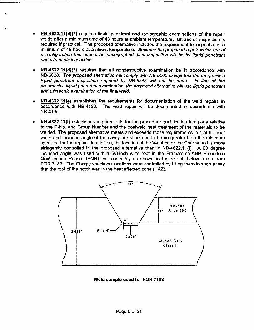
* NB-4622.11(f) establishes requirements for the procedure qualification test plate relativeto the P-No. and Group Number and the postweld heat treatment of the materials to bewelded. The proposed altemative meets and exceeds those requirements in that the rootwidth and included angle of the cavity are stipulated to be no greater than the minimumspecified for the repair. In addition, the location of the V-notch for the Charpy test is morestringently controlled in the proposed alternative than in NB-4622.1 1 (f). A 60 degreeincluded angle was used with a 5/8-inch wide root in the Framatome-ANP ProcedureQualification Record (PQR) test assembly as shown in the sketch below taken fromPQR 7183. The Charpy specimen locations were controlled by tilting them in such a waythat the root of the notch was in the heat affected zone (HAZ).
Weld sample used for POR 7183
Page 5 of 31
* NB-4622.11(g) establishes requirements for welder performance qualification relating tophysical obstructions that might impair the welder's ability to make sound repairs, which isparticularly pertinent to the SMAW manual welding process. The proposed alternativeinvolves a machine GTAW process and requires welding operators be qualified inaccordance with ASME Section IX. The use of a machine process eliminates concemabout obstructions, which might interfere with the welder's abilities since theseobstructions will have to be eliminated to accommodate the welding machine.
NB-4453.4 of Section III requires examination of the repair weld in accordance with therequirements for the original weld. The welds being made per the proposed altematives willbe partial penetration welds as described by NB-4244(d) and will meet the weld designrequirements of NB-3352.4(d). For these partial penetration welds, paragraph NB-5245requires a progressive surface examination [liquid penetrant test (PT) or magnetic particle test(MT)] at the lesser of 1/2 the maximum weld thickness or 1/2 inch as well as a surfaceexamination on the finished weld.
For the proposed altemative, the repair weld will be examined by a liquid penetrant andultrasonic examination no sooner than 48 hours after the weld has cooled to ambienttemperature in lieu of the progressive surface exams required by NB-5245.
IV. Basis for Proposed Alternative
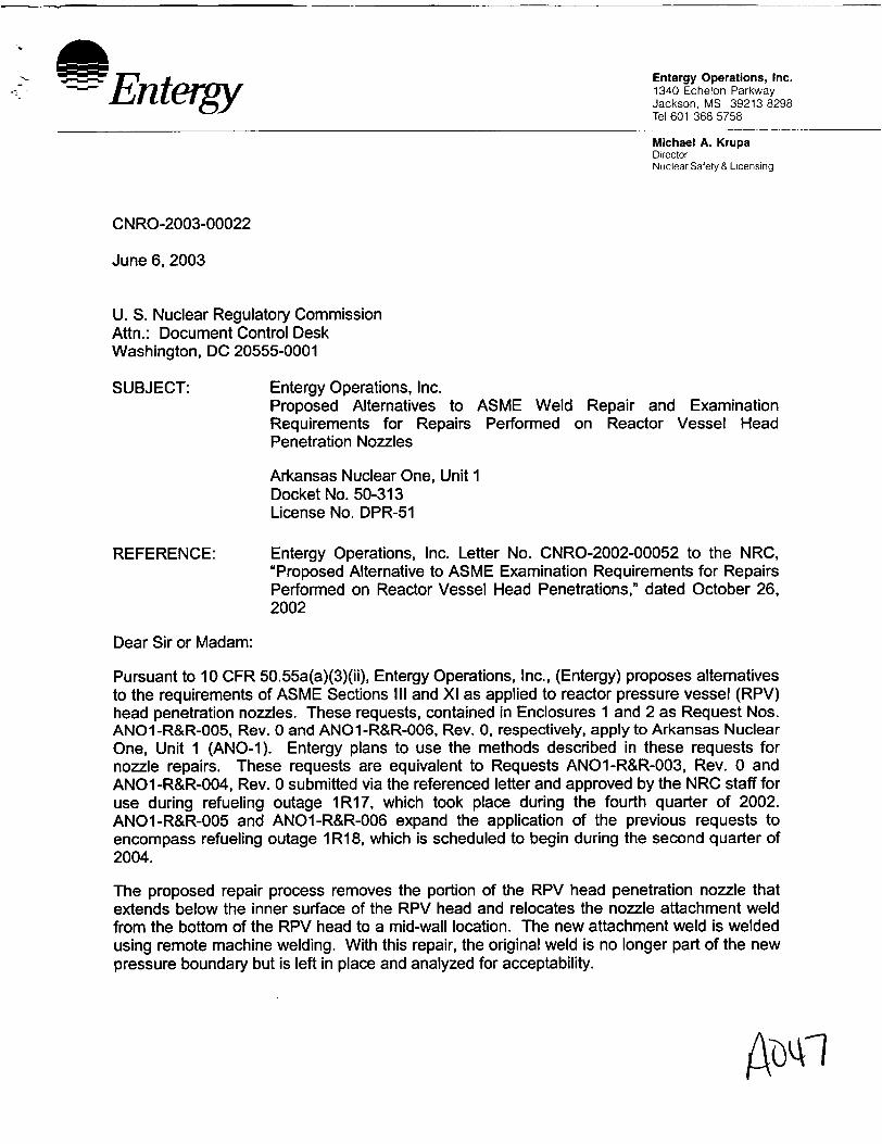
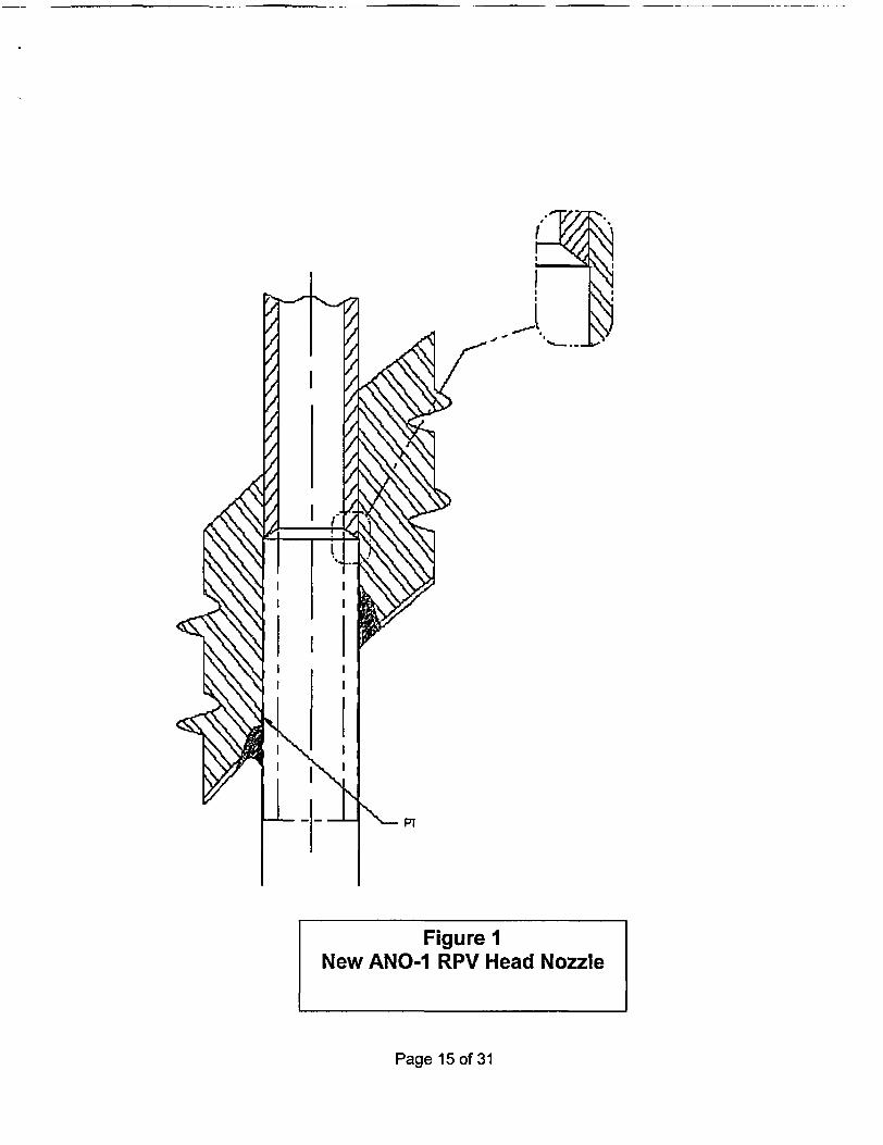
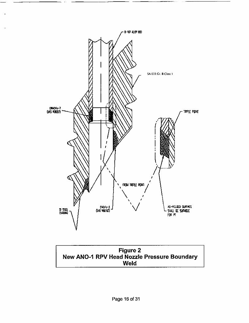
Experience gained from performing repairs to RPV head nozzles at ANO-1 and throughoutthe industry indicates that remote automated repair methods are needed to reduce radiationdose to repair personnel. Additionally, achieving and maintaining the required preheat andpost weld soak temperatures is time consuming and radiation dose intensive. Therefore, aremote semi-automated repair method utilizing a qualified machine GTAW ambienttemperature temper bead process is planned for each nozzle that requires repair. Using aremote tool from above the RPV head, each of the subject nozzles will first receive a rollexpansion into the RPV head base material. The roll expansion ensures that the nozzle willnot move during the repair operations. Second, an automated machining tool fromunderneath the RPV head will remove the lower portion of the nozzle to a depth above theexisting J-groove partial penetration weld. This operation will sever the existing J-groovepartial penetration weld from the subject RPV head nozzles and machine a bevel onto theend of the nozzles in preparation for the repair weld (see Figure 1). Third, a weld tool,utilizing the GTAW-machine process, will be used to install a new pressure boundary weldbetween the shortened nozzle and the inside bore of the RPV head base material (seeFigure 2).
This approach for repairing RPV head nozzles will significantly reduce radiation dose to repairpersonnel while still maintaining acceptable levels of quality and safety. The total radiationdose (assuming two nozzles for estimation purposes) for the proposed remote repair methodis projected to be about 10 REM. Entergy estimates the dose accumulated to provide access,install heating pads and perform the preheat and post weld heat treatment required by theconstruction code would total an additional 15 REM. In contrast, using manual repairmethods would result in a total radiation dose of approximately 60 REM.
The automated repair method described above leaves a strip of low alloy steel exposed to theprimary coolant. The effect of corrosion on the exposed area [reduction in RPV headthickness and primary coolant ferric (Fe) release] will be evaluated by Framatome-ANP. Thiscalculation will show that the general corrosion of the low alloy steel base material will be
Page 6 of 31
insignificant for the remaining life of the RPV head. (The remaining life of the RPV head willbe one operating cycle since Entergy plans to replace the ANO-1 RPV head during 1 Rl 9.)The estimate will be based on extensive industry data and Framatome-ANP experience. It isestimated that the Fe release from a total of 69 repaired RPV head nozzles will be less than15% of the total Fe release from all other sources. Entergy has determined that thisextremely low material loss and Fe release provide an acceptable level of safety.
An analysis of the new pressure boundary welds, using a 3-dimensional model of a RPV headnozzle located at the most severe hillside orientation will be performed. The softwareprogram ANSYS (general purpose finite element program that is used industry wide) will beutilized for this analysis. Per Framatome-ANP internal procedures, the ANSYS computercode is independently verified as executing properly by the solution of verification problemsusing ANSYS and then comparing the results to independently determined values.
The analytical model will include the RPV head, RPV head nozzle, repair weld and remnantportions of the original Alloy 600 welds. The model will be analyzed for thermal transientconditions as contained in the Reactor Coolant Functional Specifications. The resultingmaximum thermal gradients will be applied to the model along with the coincident internalpressure values. The ANSYS program will then calculate the stresses throughout the model(including the repair welds). The stresses will be post-processed by ANSYS routines tocategorize stresses into categories that are consistent with the criteria of the ASME Code.
The calculated stress values will be compared to the ASME Code, Section III, NB-3000criteria for:
* Design Conditions
* Normal, Operating, and Upset Conditions
* Emergency Conditions
* Faulted Conditions
* Testing Conditions
A very conservative stress concentration factor (SCF) of 4.0 will be assumed for the newpressure boundary weld.
A primary stress analysis for design conditions will be performed. A maximum PrimaryGeneral Membrane Stress Intensity (Pm) will be calculated and shown to be less than themaximum allowed by the ASME Code.
The maximum cumulative fatigue usage factor will be calculated for the point at theintersection of the bottom of the repair weld and the penetration bore and the crevice betweenthe RPV head nozzle outside surface and the RPV head bore. Allowable years of future plantoperation will be based on the maximum allowed ASME Code usage factor criterion of 1.0. Itis anticipated that the limiting location for this value is the point at the intersection of thebottom of the repair weld and the penetration bore. At the bottom of the crevice between theRPV head nozzle outside surface and the RPV head bore, the calculated fatigue usage factorfor 40 years of future operation is not expected to be limiting to the fatigue life of the repair.
Page 7 of 31
Justification for Proposed Alternatives:
NB-4331
As described below under NB-4622, the characteristics of the weld proposed for this repairhave been well defined by research and qualification for this and similar applications.
NB-4622
The proposed alternative requires the use of an automatic or machine GTAW temper beadtechnique without the specified preheat or post weld heat treatment of the Construction Code.The proposed alternative will include the requirements of paragraphs 1.0 through 5.0 ofAttachment 1, "Dissimilar Metal Welding Using Ambient Temperature Machine GTAWTemper Bead Technique." The alternative will be used to make welds joining P-No. 3, RPVhead material to P-No. 43 RPV head nozzle material using F-No. 43 filler material.
Results of procedure qualification work undertaken to date indicate that the process producessound and tough welds. For instance, typical tensile test results have been ductile breaks inthe weld metal.
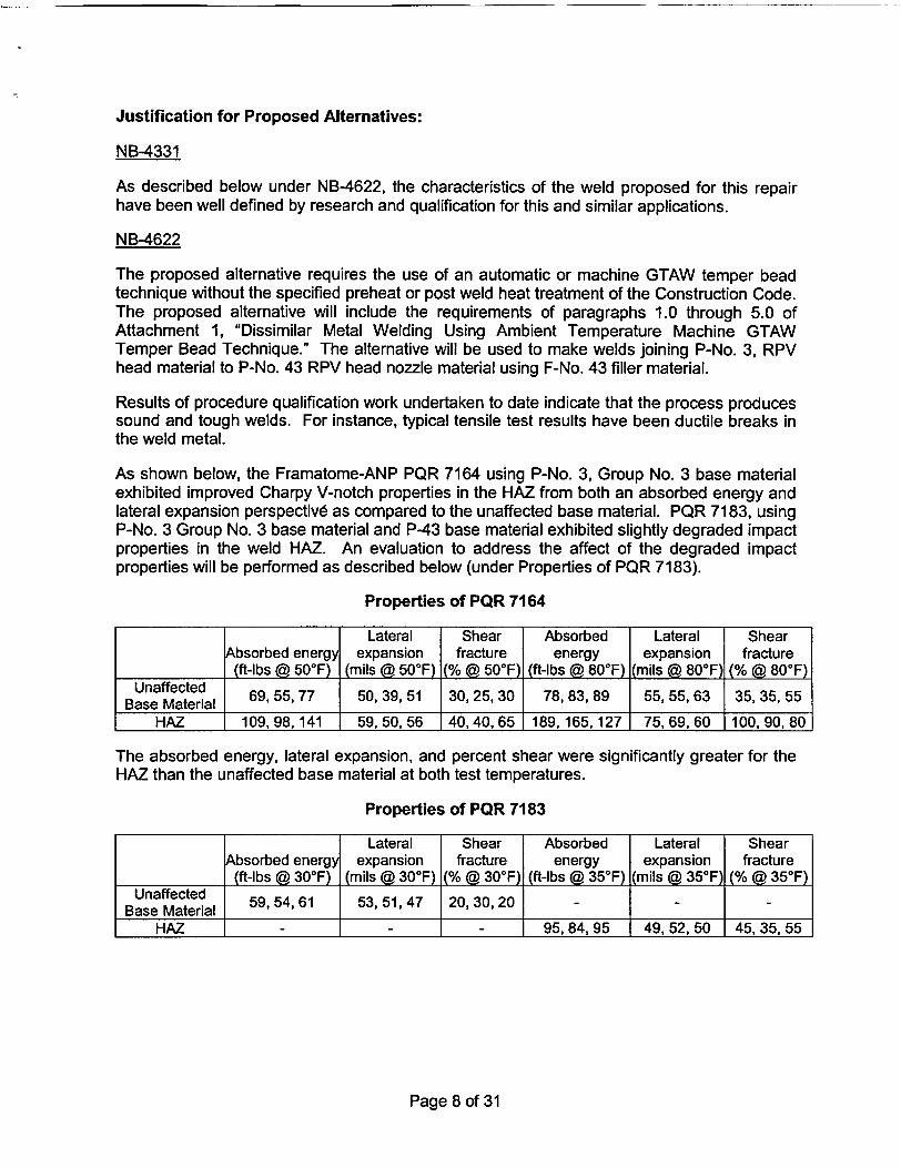
As shown below, the Framatome-ANP PQR 7164 using P-No. 3, Group No. 3 base materialexhibited improved Charpy V-notch properties in the HAZ from both an absorbed energy andlateral expansion perspective as compared to the unaffected base material. PQR 7183, usingP-No. 3 Group No. 3 base material and P-43 base material exhibited slightly degraded impactproperties in the weld HAZ. An evaluation to address the affect of the degraded impactproperties will be performed as described below (under Properties of PQR 7183).
Properties of PQR 7164
Lateral Shear Absorbed Lateral ShearAbsorbed energy expansion fracture energy expansion fracture
(ft-lbs @ 50°F) (mils @ 50°F) (% @ 500F) (ft-lbs @ 80°F) (mils @ 800F) (% @ 800F)Unaffected 69, 55, 77 50, 39, 51 30, 25, 30 78, 83, 89 55, 55, 63 35, 35, 55
HAZ 109,98,141 59, 50, 56 40,40, 65 189,165,127* 75, 69, 60 1100, 90, 80
The absorbed energy, lateral expansion, and percent shear were significantly greater for theHAZ than the unaffected base material at both test temperatures.
Properties of PQR 7183
Lateral Shear Absorbed Lateral ShearAbsorbed energy expansion fracture energy expansion fracture
(ft-lbs @ 30°F) (mils @ 30°F) (% @ 30°F) (ft-lbs @ 35°F) (mils @ 35°F) (% @ 35°F)Unaffected 59, 54, 61 53, 51, 47 20, 30, 20 - - -
HAZ - - - 95, 84, 95 49, 52, 50 45, 35, 55
Page 8 of 31
The results of this second PQR require that the Reference Temperature (RTNDT) of the basematerial be adjusted in accordance with the rules of NB-4335.2. This adjustment temperatureincreases the RTNDT of the RPV head by 5F. Entergy will evaluate the impact of the 5FRTNDT adjustment temperature on the RPV head against the fracture toughness requirementsof 10 CFR 50 Appendix G and existing Technical Specification pressure-temperature limits forthe RPV head and reactor coolant system. However, it is expected that this minordegradation will have no effect on the safe operation of the RPV head or TechnicalSpecification pressure-temperature limits.
Framatome-ANP has previously qualified the GTAW temper bead process in support ofASME approval of Code Case N-606-1, "Similar and Dissimilar Metal Welding Using AmbientTemperature Machine GTAW Temper Bead Technique for Boiling Water Reactor (BWR) CRDHousing/Stub Tube Repairs." The qualifications were performed at room temperature withcooling water to limit the maximum interpass temperature to a maximum of 1000F. Thequalifications were performed on the same P-3 Group-3 base material as proposed for theRPV head nozzle repairs, using the same filler material, i.e. Alloy 52 AWS Class ERNiCrFe-7,with similar low heat input controls as will be used in the repairs. Also, the qualifications didnot include a post weld heat soak.
The Welding Procedure Qualifications supporting the applicable WPS to be used for therepair weld are for P-No. 3 Group No. 3 base material welded with F-No. 43 filler metal andP-No. 3 to P-No. 43 base material welded with F-No. 43 filler metal. The use of this WPS, forwelding P-No.43 to P-No.3 Group No. 3 with F-No. 43 filler metal, i.e., dissimilar metalwelding, is justified based on the following:
* PQR 55-PQ7164, as discussed above, supporting the ambient temperature temper beadWPS for welding, was a groove weld performed using F-No. 43 filler wire on P-No. 3Group No. 3 base material. The PQR 55-PQ7164 groove (cavity) in the P-No. 3 GroupNo. 3 base material coupon was 23/4 inches deep with a 3/4-inch wide root and 30 degreeside bevels (60 degree included angle). All the effects of welding to the P-3 base materialwith F-No. 43 filler metal have been verified by full thickness transverse tensile tests, fullthickness transverse side bends, and impact testing.
* The PQR 55-PQ7183 is similar except that one side of the weld was P-43 material andthe groove was 11/2 inches deep.
The NB-4622 temper bead procedure requires a 350°F preheat and a post weld soak at450 - 660°F for 4 hours for P-No. 3 materials. Typically, these kinds of restrictions are usedto mitigate the effects of the solution of atomic hydrogen in ferritic materials prone tohydrogen embrittlement cracking. The susceptibility of ferritic steels is directly related to theirability to transform to martensite with appropriate heat treatment. The P-No. 3 material of theRPV head is able to produce martensite from the heating and cooling cycles associated withwelding. However, the proposed alternative temper bead procedure utilizes a weldingprocess that is inherently free of hydrogen. The GTAW process relies on bare welding fillermetals with no flux to trap moisture. An inert gas blanket positively shields the weld andsurrounding material from the atmosphere and moisture it may contain. To further reduce thelikelihood of any hydrogen evolution or absorption, the alternative procedure requiresparticular care to ensure the weld region is free of all sources of hydrogen. The GTAWprocess will be shielded with welding grade argon which typically produces porosity freewelds. The gas would typically have no more than 1 ppm of hydrogen (H2) and no more than1 ppm of water vapor (H20). A typical argon flow rate would be about 15 to 50 cfh and would
Page 9 of 31
be adjusted to assure adequate shielding of the weld without creating a venturi affect thatmight draw oxygen or water vapor from the ambient atmosphere into the weld.
Entergy has concluded that quality temper bead welds can be performed with 50°F minimumpreheat and no post heat treatment based on ASME committee approval of Code Case N-638and Framatome-ANP prior welding procedure qualification test data using machine GTAWambient temperature temper bead welding. The proposed alternative (Attachment 1)provides a technique for repair welding 1/8-inch of the ferritic base metal of the RPV head.
NB-4622.1 i (c)(5)
The closure head preheat temperature will be essentially the same as the reactor buildingambient temperature; therefore, closure head preheat temperature monitoring in the weldregion using thermocouples is unnecessary and would result in additional personnel doseassociated with thermocouple placement and removal. Consequently, preheat temperatureverification by use of a contact pyrometer on accessible areas of the closure head issufficient.
In lieu of using thermocouples for interpass temperature measurements, calculations will beperformed to show that the maximum interpass temperature will never be exceeded based ona maximum allowable low welding heat input, weld bead placement, travel speed, andconservative preheat temperature assumptions. The calculation will support the conclusionthat, when using the maximum heat input through the third layer of the weld, the interpasstemperature retums to near ambient temperature. Heat input beyond the third layer will nothave a metallurgical effect on the low alloy steel HAZ.
The calculation will be based on a typical inter-bead time interval of five minutes. The fiveminute inter-bead interval is based on: 1) the time required to explore the previous welddeposit with the two remote cameras housed in the weld head, 2) time to shift the startinglocation of the next weld bead circumferentially away from the end of the previous weld-bead,and 3) time to shift the starting location of the next bead axially to insure a 50% weld beadoverlap required to properly execute the temper bead technique.
A welding mockup on the full size Midland RPV head, which is similar to the ANO-1 RPVhead, was used to demonstrate the welding technique described herein. During the mockup,thermocouples were placed to monitor the temperature of the closure head during welding.Thermocouples were placed on the outside surface of the closure head within a 5-inch bandsurrounding the RPV head nozzle. Three other thermocouples were placed on the closurehead inside surface. One of the three thermocouples was placed 11/2 inches from the RPVhead nozzle penetration, on the lower hillside. The other inside surface thermocouples wereplaced at the edge of the 5-inch band surrounding the RPV head nozzle, one on the lowerhillside, the second on the upper hillside. During the mockup, all thermocouples fluctuatedless than 1 5°F throughout the welding cycle. Based on past experience, it is believed that thetemperature fluctuation was due more to the resistance heating temperature variations thanthe low heat input from the welding process. For the Midland RPV head mockup application,300°F minimum preheat temperature was used. Therefore, for ambient temperatureconditions used for this repair, maintenance of the 350°F maximum interpass temperature willcertainly not be a concem.
Page 10 of 31
NB-4622.11 (d)(2)/ NB-4622. 11 (d)(3)/NB-4453.4
UT will be performed in lieu of radiographic testing (RT) due to the repair weld configuration.Meaningful RT cannot be performed as can be seen in the applicable attached figures. Theweld configuration and geometry of the penetration in the head provide an obstruction for thex-ray path and interpretation would be very difficult. UT will be substituted for the RT andqualified to evaluate defects in the repair weld and at the base metal interface. Thisexamination method is considered adequate and superior to RT for this geometry. The newstructural weld is sized like a coaxial cylinder partial penetration weld. ASME Code Section IIIconstruction rules require progressive PT of partial penetration welds. The Section III originalrequirements for progressive PT were in lieu of volumetric examination. Volumetricexamination is not practical for the conventional partial penetration weld configurations. Inthis case the weld is suitable, except for the taper transition, for UT and a final surface PT willbe performed.
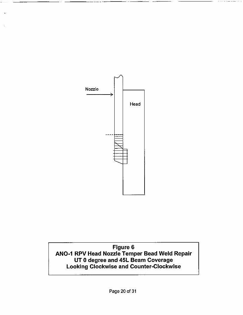
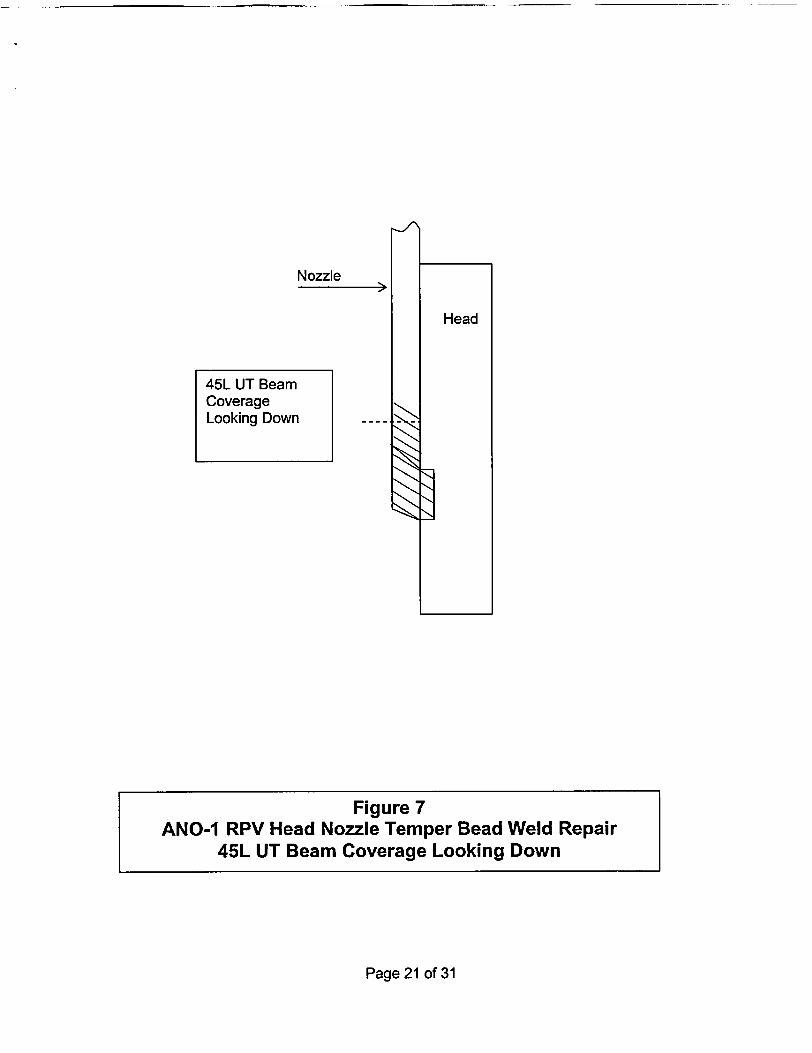
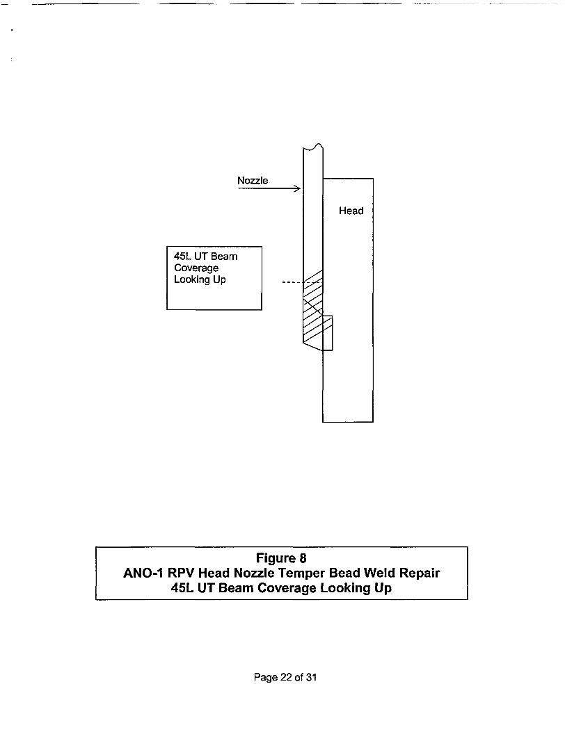
The effectiveness of the UT techniques to characterize the weld defects has been qualified bydemonstration on a mockup of the repair temper bead weld involving the same materials usedfor repair. Notches were machined into the mockup at depths of 0.10 inch, 0.15 inch, and0.25 inch in order to quantify the ability to characterize the depth of penetration into thenozzle. The depth characterization is performed using tip diffraction UT techniques that havethe ability to measure the depth of a reflector relative to the nozzle bore. Each of the notchesin the mockup could be measured using the 45-degree transducer. During the examinationlongitudinal wave angle beams of 45 degrees and 70 degrees are used. These beams aredirected along the nozzle axis looking up and down. The downward looking beams areeffective at detecting defects near the root of the weld because of the impedance change atthe triple point (intersection of weld material, penetration tube, and vessel head). The45-degree transducer is effective at depth characterization by measuring the time interval tothe tip of the reflector relative to the transducer contact surface. The 70-degree longitudinalwave provides additional qualitative data to support information obtained with the 45-degreetransducer. Together, these transducers provide good characterization of possible defects.These techniques are routinely used for examination of austenitic welds in the nuclearindustry for flaw detection and sizing.
In addition to the 45 and 70-degree beam angles described above, the weld is also examinedin the circumferential direction using 45-degree longitudinal waves in both the clockwise andcounterclockwise directions to look for transverse fabrication flaws. A 0-degree transducer isalso used to look radially outward to examine the weld and adjacent material for laminar typeflaws and evidence of under bead cracking.
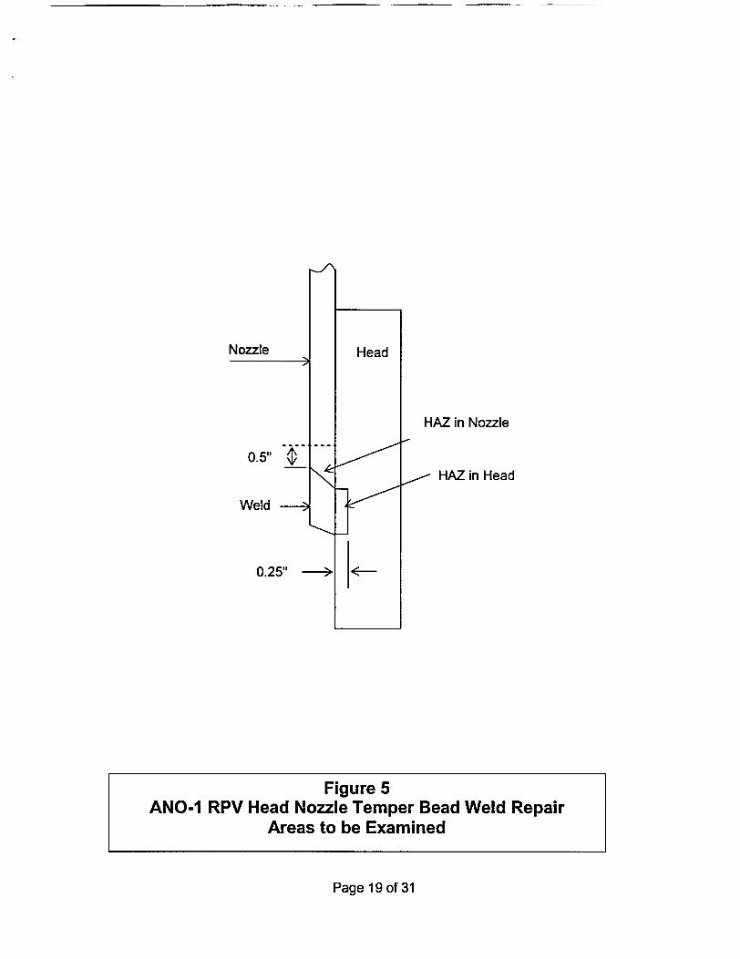
The UT transducers and delivery tooling are capable of scanning from cylindrical surfaceswith inside diameters near 2.75 inches. The UT equipment is not capable of scanning fromthe face of the taper. Approximately 70% of the weld surface will be scanned by UT.Approximately 83% of the RPV head ferritic steel HAZ will be covered by the UT. Thetransducers to be used are shown in Table 1. The UT coverage volumes are shown inFigures 5 through 10 for the various scans. Additionally, the final modification configurationand surrounding ferritic steel area affected by the welding is either inaccessible or extremelydifficult to access, to obtain the necessary scans.
Page 11 of 31
UT of the repair weld and HAZ are limited by the repair configuration. As can be observedfrom Figure 2, the RPV head nozzle weld repair configuration limits access to the ferritic steelbase material above the weld as well as scanning from the taper at the bottom of the weld.See also Figures 5 through 10 and Table 1.
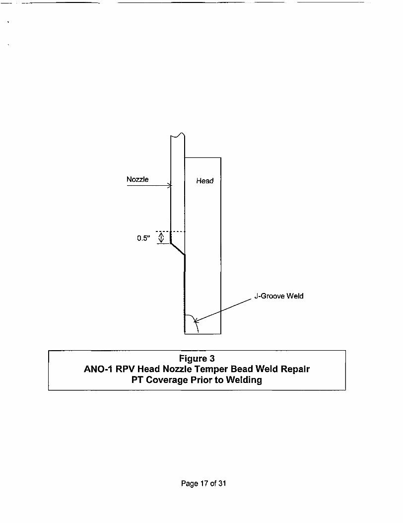
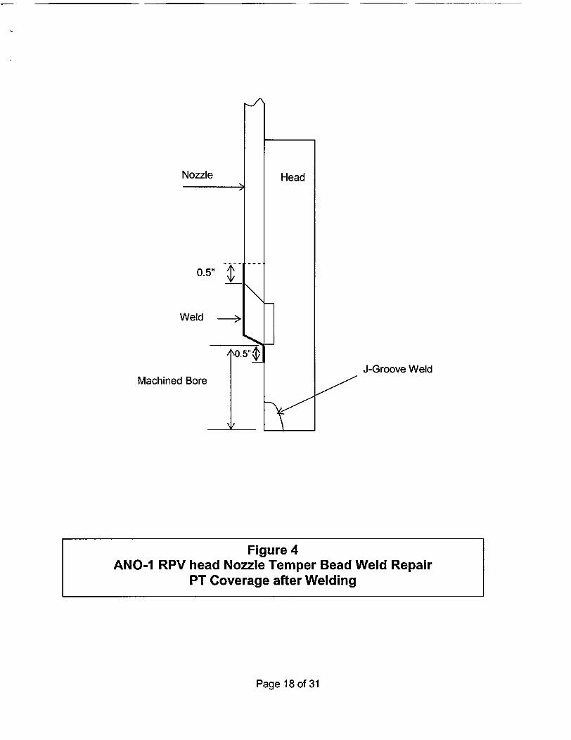
The PT examination extent is consistent with the Construction Code requirements. PTexamination of the entire ferritic steel bore will be performed after removal by boring of thelower end of the existing RPV head nozzle prior to welding. As can be observed from Figures2, 3, and 4, the configuration of the new RPV head nozzle repair configuration limits access tothe ferritic steel base material. The ferritic steel base material area above the new weld isinaccessible due to the RPV head nozzle. The ferritic steel base material below the new weldand within Y2 inch of the bottom weld toe will be PT examined subsequent to welding.
The welding head has video capability for torch positioning and monitoring during welding.The operator observes the welding operation as well as observing each bead deposited priorto welding the next bead. The video clarity and resolution is such that the welding operatorcan observe a 1/2 mil diameter color contrast wire.
Based on the above information, it may be concluded that using the proposed alternativeambient temperature temper bead weld technique (Attachment 1) is an acceptable alternativeto Code requirements and will produce sound, permanent repair welds and an acceptablelevel of quality and safety.
This proposed alternative, submitted as ANO1-R&R-003, was previously approved by theNRC staff for use during the previous refueling outage 1 Ri 7 at ANO-1.
V. Duration of the Proposed Alternative
Entergy plans to replace the ANO-1 RPV head during Refueling Outage 1R19, which isscheduled to begin during the fall of 2005. Therefore, any repairs made in accordance withthis request will be limited to one operating cycle.
A Framatome-ANP evaluation will be performed to determine the time for a postulated crackto grow 75% through-wall in the Alloy 600 nozzle material above the repair weld. Theevaluation will consider RPV head nozzles in the as-repaired condition and will encompassinitiation and crack growth due to primary water stress corrosion cracking (PWSCC). With noapplication of abrasive water jet (AWJ) remediation, Entergy has estimated 2.5 effective fullpower years (EFPY) for a crack to grow 75% through-wall. Since Entergy plans to replacethe ANO-1 RPV head prior to the end of service life (2.5 EFPY), AWJ remediation is notnecessary.
Flaw growth rates for evaluation will be assumed to follow a 4 mm/year rate, which boundsany variation in flaw growth through the Alloy 600 material as a result of the weld repair.
Given these expected results, the proposed inspection schedules given above, and theplanned replacement date for the ANO-1 RPV head, Entergy believes the proposedalternatives to the ASME code requirements are justified.
The proposed alternatives are applicable to the repairs and examinations after repair to anyANO-1 RPV head nozzles. This request is applicable to the repair of RPV head nozzles withleaks or other unacceptable conditions that may be identified prior to replacing the RPV head.
Page 12of31
VI. Implementation Schedule
This request will be implemented during upcoming refueling outage 1 R18, which is scheduledto begin during the second quarter of 2004. As mentioned above, Entergy plans to replacethe ANO-1 RPV head during Refueling Outage 1R19, which is scheduled to begin during thefall of 2005.
Page 13 of 31
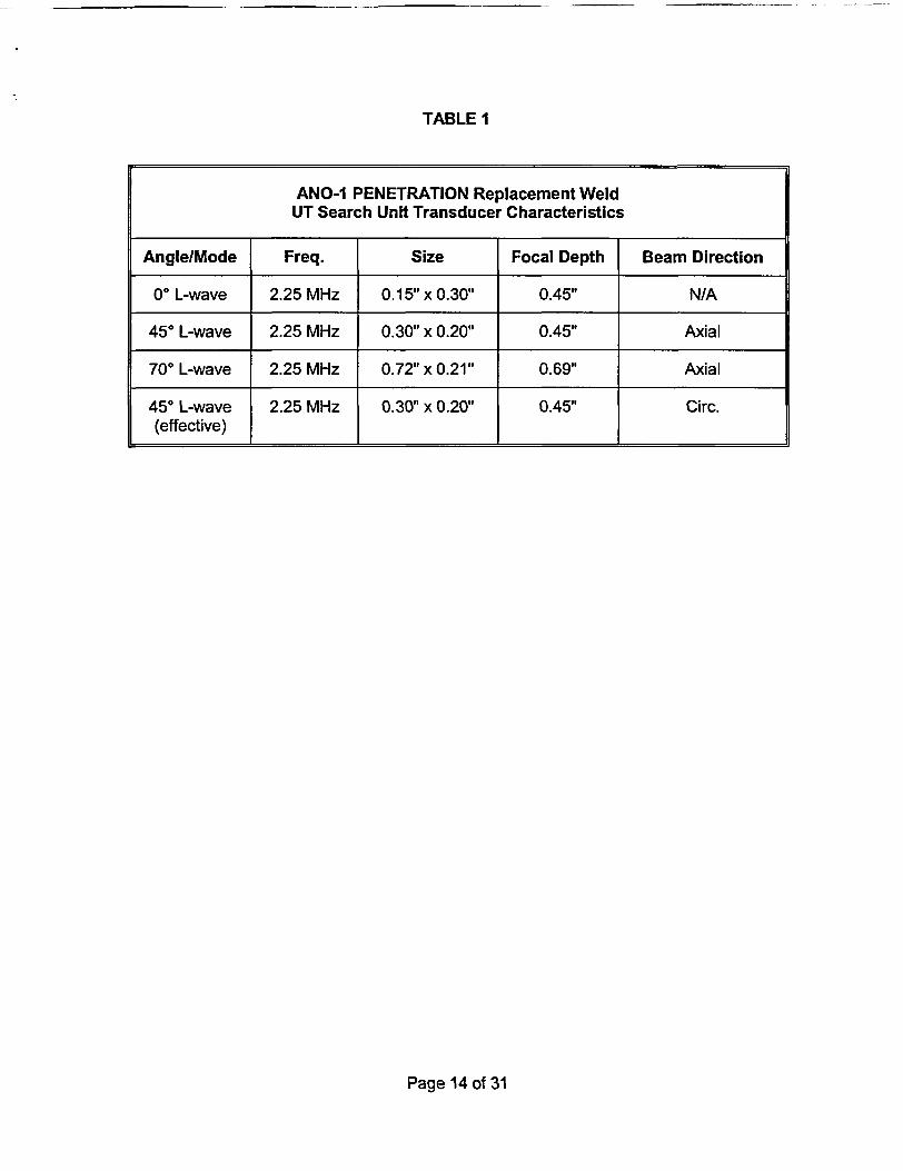
TABLE 1
Page 14 of 31
ANO-1 PENETRATION Replacement WeldUT Search Unit Transducer Characteristics
Angle/Mode Freq. Size Focal Depth Beam Direction
O L-wave 2.25 MHz 0.15" x 0.30" 0.45" N/A
450 L-wave 2.25 MHz 0.30" x 0.20" 0.45" Axial
70° L-wave 2.25 MHz 0.72" x 0.21" 0.69" Axial
450 L-wave 2.25 MHz 0.30" x 0.20" 0.45" Circ.(effective)
IaI
Page 15 of 31
Figure 1New ANO-1 RPV Head Nozzle
l-ir#IVkOD
SA-533 Gr. B Class 1
(DNS Mani irIPLE PNI
I
I
Itrc- /t -WELCD IFACSI 11[EL |lilE q@j1 ) VI4AJ.L GE SJfliaE
N~~~~~~~ru
Page 16 of 31
Nozzle
0.5" __
J-Groove Weld
Page 17 of 31
Head
Figure 3ANO-1 RPV Head Nozzle Temper Bead Weld Repair
PT Coverage Prior to Welding
Nozzle
0.5"
Weld
/
McieBoI J-Groove WeldMachined Bore / -
Page 18of31
Figure 4ANO-1 RPV head Nozzle Temper Bead Weld Repair
PT Coverage after Welding
NV/
HAZ in Nozzle
- HAZ in Head
Page 19 of 31
Nozzle
0.5"
Weld
0.25"
Figure 5ANO-1 RPV Head Nozzle Temper Bead Weld Repair
Areas to be Examined
Nozzle
Head
Page 20 of 31
Figure 6ANO-1 RPV Head Nozzle Temper Bead Weld Repair
UT 0 degree and 45L Beam CoverageLooking Clockwise and Counter-Clockwise
Nozzle
Page 21 of 31
45L UT BeamCoverageLooking Down
Figure 7ANO-1 RPV Head Nozzle Temper Bead Weld Repair
45L UT Beam Coverage Looking Down
Nozzle
Figure 8ANO-1 RPV Head Nozzle Temper Bead Weld Repair
45L UT Beam Coverage Looking Up
Page 22 of 31
45L UT BeamCoverageLooking Up
Nozzle
Page 23 of 31
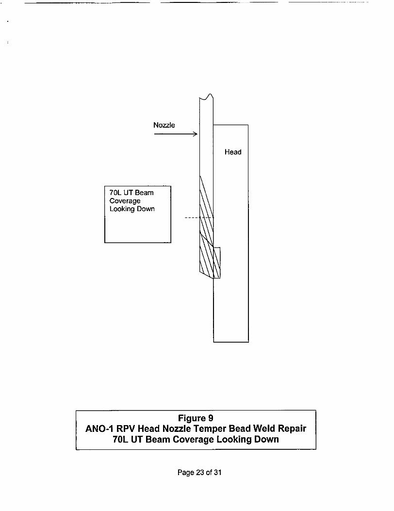
70L UT BeamCoverageLooking Down
Figure 9ANO-1 RPV Head Nozzle Temper Bead Weld Repair
70L UT Beam Coverage Looking Down
Nozzle
Page 24 of 31
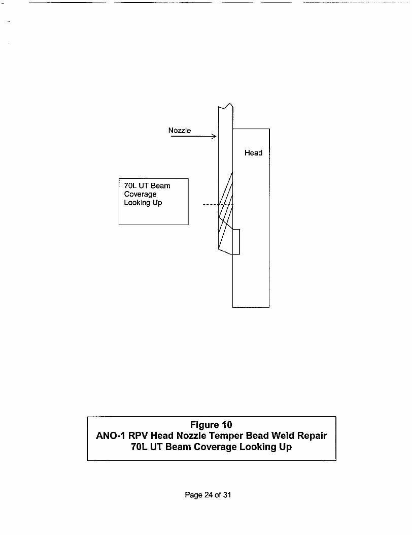
70L UT BeamCoverageLooking Up
Figure 10ANO-1 RPV Head Nozzle Temper Bead Weld Repair
70L UT Beam Coverage Looking Up
Attachment 1 toANO1-R&R-005, Rev. 0
REQUEST NO. ANOI-R&R-005, Rev. 0
ATTACHMENT I
DISSIMILAR METAL WELDING USING AMBIENT TEMPERATUREMACHINE GTAW TEMPER BEAD TECHNIQUE
Page 25 of 31
Attachment 1 toANO1-R&R-005, Rev. 0
DISSIMILAR METAL WELDING USING AMBIENT TEMPERATUREMACHINE GTAW TEMPER BEAD TECHNIQUE
Entergy plans to perform RPV head nozzle repairs by welding the RPV head (P-No. 3 basematerial) and nozzle (P-No. 43 base material) with filler material F-No. 43, in accordance withthe following:
1.0 General Requirements:
(a) The maximum area of an individual weld based on the finished surface will be less than100 square inches, and the depth of the weld will not be greater than one-half of theferritic base metal thickness.
(b) Repair/replacement activities on a dissimilar-metal weld are limited to those along thefusion line of a nonferritic weld to ferritic base material on which 1/8 inch or less ofnonferritic weld deposit exists above the original fusion line.
(c) If a defect penetrates into the ferritic base material, repair of the base material, using anonferritic weld filler material, may be performed provided the depth of repair in the basematerial does not exceed 3/8 inch.
(d) Prior to welding, the area to be welded and a band around the area of at least 1 timesthe component thickness (or 5 inches, whichever is less) will be at least 500F.
(e) Welding materials will meet the Owner's Requirements and the Construction Code andCases specified in the repair/replacement plan. Welding materials will be controlled sothat they are identified as acceptable until consumed.
(f) Peening will not be used, however, the weldment final surface will be abrasive water jetconditioned.
2.0 Welding Qualifications:
The welding procedures and the welding operators shall be qualified in accordance withSection IX and the requirements of paragraphs 2.1 and 2.2.
2.1 Procedure Qualification
(a) The ferritic steel base material for the welding procedure qualification is P-No. 3 GroupNo. 3 which is the same P-No. and Group No. as the low alloy steel closure head basematerial to be welded. The base material shall be postweld heat treated to at least thetime and temperature that was applied to the materials being welded. The filler metal isF-No. 43.
(b) The root width and included angle of the cavity in the test assembly will be no greaterthan the minimum specified for the repair.
(c) The maximum interpass temperature for the first three layers of the test assembly will be150 0F.
Page 26 of 31
Attachment I toANO1-R&R-005, Rev. 0
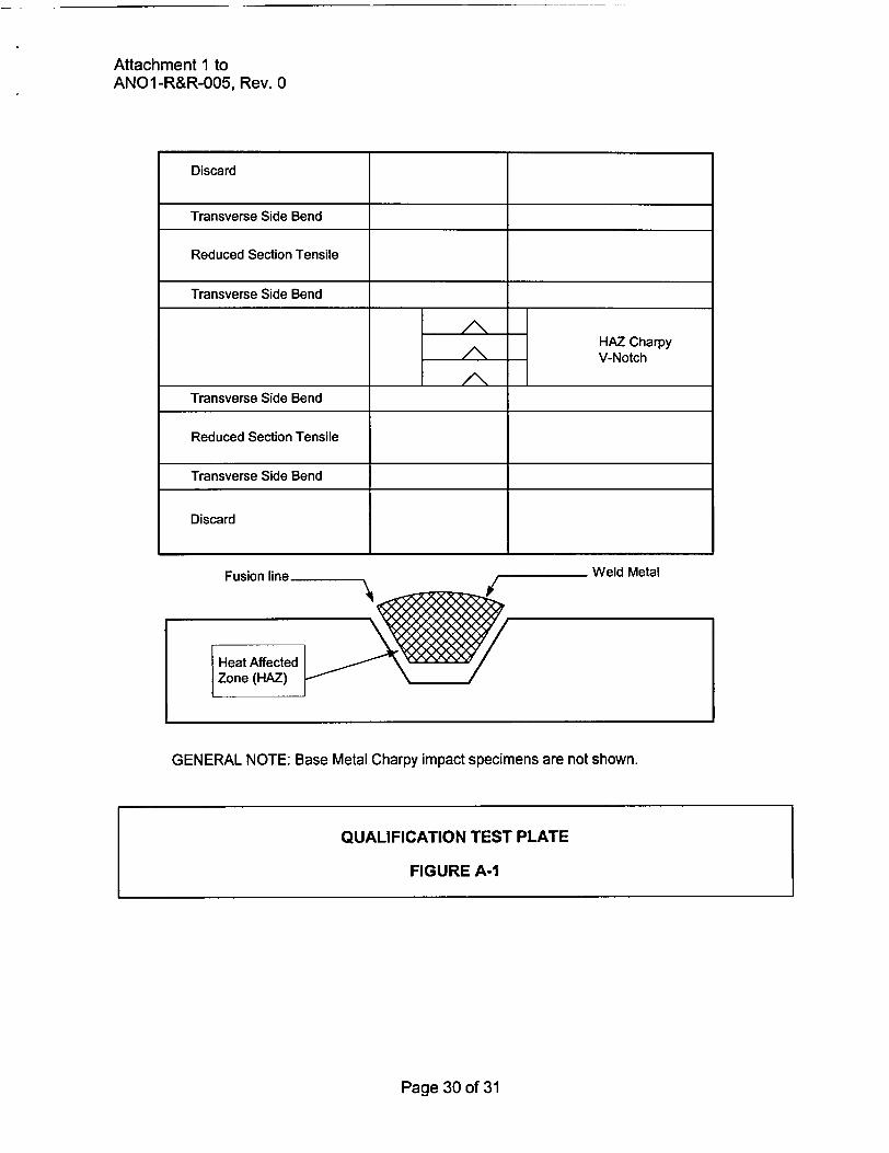
(d) The ferritic steel P-No. 3 Group No. 3 base material test assembly cavity depth will be atleast one-half the depth of the weld to be installed during the repair/replacement activity,and at least 1 inch. The test assembly thickness will be at least twice the test assemblycavity depth. The test assembly will be large enough to permit removal of the requiredtest specimens. The test assembly dimensions surrounding the cavity will be at leastthe test assembly thickness, and at least 6 inches. The qualification test plate will beprepared in accordance with Figure A-1.
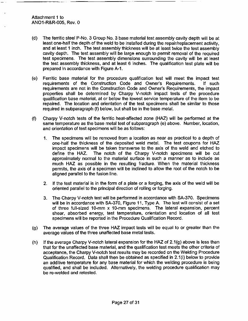
(e) Ferritic base material for the procedure qualification test will meet the impact testrequirements of the Construction Code and Owner's Requirements. If suchrequirements are not in the Construction Code and Owner's Requirements, the impactproperties shall be determined by Charpy V-notch impact tests of the procedurequalification base material, at or below the lowest service temperature of the item to berepaired. The location and orientation of the test specimens shall be similar to thoserequired in subparagraph (f) below, but shall be in the base metal.
(f) Charpy V-notch tests of the ferritic heat-affected zone (HAZ) will be performed at thesame temperature as the base metal test of subparagraph (e) above. Number, location,and orientation of test specimens will be as follows:
1. The specimens will be removed from a location as near as practical to a depth ofone-half the thickness of the deposited weld metal. The test coupons for HAZimpact specimens will be taken transverse to the axis of the weld and etched todefine the HAZ. The notch of the Charpy V-notch specimens will be cutapproximately normal to the material surface in such a manner as to include asmuch HAZ as possible in the resulting fracture. When the material thicknesspermits, the axis of a specimen will be inclined to allow the root of the notch to bealigned parallel to the fusion line.
2. If the test material is in the form of a plate or a forging, the axis of the weld will beoriented parallel to the principal direction of rolling or forging.
3. The Charpy V-notch test will be performed in accordance with SA-370. Specimenswill be in accordance with SA-370, Figure 11, Type A. The test will consist of a setof three full-sized 10-mm x 10-mm specimens. The lateral expansion, percentshear, absorbed energy, test temperature, orientation and location of all testspecimens will be reported in the Procedure Qualification Record.
(g) The average values of the three HAZ impact tests will be equal to or greater than theaverage values of the three unaffected base metal tests.
(h) If the average Charpy V-notch lateral expansion for the HAZ of 2.1(g) above is less thanthat for the unaffected base material, and the qualification test meets the other criteria ofacceptance, the Charpy V-notch test results may be recorded on the Welding ProcedureQualification Record. Data shall then be obtained as specified in 2.1 (i) below to providean additive temperature for any base material for which the welding procedure is beingqualified, and shall be included. Alternatively, the welding procedure qualification maybe re-welded and retested.
Page 27 of 31
Attachment 1 toANO1-R&R-005, Rev. 0
(i) The data for use in 2.1 (h) above shall be developed by performing additional CharpyV-notch tests on either the welding procedure qualification HAZ or the unaffected basematerial, or both, at temperatures which provide lateral expansion values equal to orgreater than 35 mils. The average lateral expansion data for the HAZ and theunaffected base material shall be plotted on a lateral expansion-temperature chart. Thetemperatures at which these two sets of data exhibit a common lateral expansion valueequal to or greater than 35 mils shall be determined. The determined temperature forthe unaffected base material shall be subtracted from the similarly determinedtemperature for the HAZ. This difference shall be used in 2.1 (h) above as theadjustment temperature. The adjustment temperature shall be added to the highest nilductility temperature (RTNDT) temperature for all of the base material to be welded bythis procedure in production. If the temperature difference is zero or is a negativenumber, no adjustment is required for the base material to be welded in production.
2.2 Performance Qualification
Welding operators will be qualified in accordance with ASME Section IX.
3.0 Welding Procedure Requirements
The welding procedure shall include the following requirements:
(a) The weld metal will be deposited by machine GTAW process.
(b) Dissimilar metal welds shall be made using F-No. 43 weld metal (QW-432) for P-No. 43to P-No. 3 weld joints.
(c) The ferritic steel area to be welded will be buttered with a deposit of at least three layersto achieve at least 1/8 inch overlay thickness as shown in Figure A-2, steps 1 through 3,with the heat input for each layer controlled to within ±10% of that used in the procedurequalification test. Particular care will be taken in placement of the weld layers at theweld toe area of the ferritic material to ensure that the ferritic HAZ is tempered.Subsequent layers will be deposited with a heat input not exceeding that used for layersbeyond the third layer in the procedure qualification.
(d) The maximum interpass temperature for field applications will be 350°F regardless ofthe interpass temperature during qualification. The new weld is inaccessible formounting thermocouples near the weld. Therefore, thermocouples will not be used tomonitor interpass temperature. Preheat temperature will be monitored using contactpyrometers, on accessible areas of the closure head external surface(s).
4.0 Examination
(a) Prior to welding, a surface examination will be performed on the area to be welded.
(b) The final weld surface and adjacent HAZ shall be examined using surface and ultrasonicmethods when the completed weld has been at ambient temperature for at least 48hours.
Page 28 of 31
Attachment 1 toANO1-R&R-005, Rev. 0
(c) The purpose for the examination of the band is to assure all flaws associated with theweld repair area have been removed or addressed. However, the band around the areadefined in paragraph 1.0(d) cannot be examined due to the physical configuration of thepartial penetration weld. The final examination of the new weld repair and immediatesurrounding area within the band will be sufficient to verify that defects have not beeninduced in the low alloy RPV head material due to the welding process. Liquidpenetrant (PT) coverage is shown in Figures 3 and 4 of ANO1-R&R-005. Ultrasonictesting (UT) will be performed scanning from the ID surface of the weld, excluding thetransition taper portion at the bottom of the weld and adjacent portion of the RPV headnozzle bore. The UT is qualified to detect flaws in the repair weld and base metalinterface in the repair region, to the maximum practical extent. The examination extent isconsistent with the Construction Code requirements.
(d) NDE personnel will be qualified in accordance with IWA-2300 or NB-5500.
(e) Surface examination acceptance criteria will be in accordance with NB-5350. Ultrasonicexamination acceptance criteria will be in accordance with NB-5330.
5.0 Documentation
Repairs will be documented on Form NIS-2. Alternatively, repairs may be documented onForm NIS-2A as described in Code Case N-532 if prior approval is obtained from the NRC.
Page 29 of 31
Attachment 1 toANO1-R&R-005, Rev. 0
GENERAL NOTE: Base Metal Charpy impact specimens are not shown.
Page 30 of 31
Discard
Transverse Side Bend-r t
Reduced Section Tensile
I. I
Transverse Side Bend
HAZ CharpyA _ ~~V-Notch
Transverse Side Bend
Reduced Section Tensile
Transverse Side Bend
Discard
QUALIFICATION TEST PLATE
FIGURE A-1
Attachment 1 toANO1-R&R-005, Rev. 0
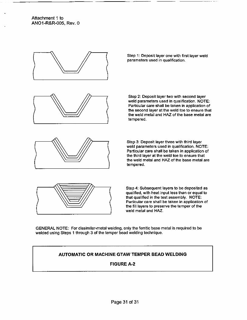
Step 1: Deposit layer one with first layer weldparameters used in qualification.
Step 2: Deposit layer two with second layerweld parameters used in qualification. NOTE:Particular care shall be taken in application ofthe second layer at the weld toe to ensure thatthe weld metal and HAZ of the base metal aretempered.
Step 3: Deposit layer three with third layerweld parameters used in qualification. NOTE:Particular care shall be taken in application ofthe third layer at the weld toe to ensure thatthe weld metal and HAZ of the base metal aretempered.
Step 4: Subsequent layers to be deposited asqualified, with heat input less than or equal tothat qualified in the test assembly. NOTE:Particular care shall be taken in application ofthe fill layers to preserve the temper of theweld metal and HAZ.
GENERAL NOTE: For dissimilar-metal welding, only the ferritic base metal is required to bewelded using Steps 1 through 3 of the temper bead welding technique.
Page 31 of 31
AUTOMATIC OR MACHINE GTAW TEMPER BEAD WELDING
FIGURE A-2
ENCLOSURE 2
CNRO-2003-00022
REQUEST FOR ALTERNATIVEANOI-R&R-006, Rev. 0
ENTERGY OPERATIONS, INC.ARKANSAS NUCLEAR ONE, UNIT I
3rd 10-YEAR INTERVALREQUEST No. ANO1-R&R-006, Rev. 0
REFERENCE CODE:
The original code of construction for Arkansas Nuclear One, Unit 1 (ANO-1) is ASME SectionIII, 1965 Edition with Addenda through Summer, 1967. The components (including supports)may meet the requirements set forth in subsequent editions and addenda of the ASME Codeincorporated by reference in 10 CFR 50.55a(b) subject to the limitations and modificationslisted therein and subject to NRC approval. The codes of record for the repairs describedwithin this request are the 1989 Edition of ASME Section III and 1992 Edition of ASMESection Xl codes. ANO-1 is in its third (3rd) 10-Year Inservice Inspection interval.
I. System/Component(s)
a) Name of component:
Reactor Pressure Vessel (RPV) head nozzles (There are 69 nozzles welded to theRPV head.)
b) Function:
These welds serve as the pressure boundary weld for the RPV head nozzle andRPV head.
c) ASME Code Class:
The RPV head and RPV head nozzles are ASME Class 1.
d) Category:
Examination Category B-E, Pressure Retaining Partial Penetration Welds in Vessels;Item No. B4.12
II. Code Requirements
IWA-4310 requires in part that "Defects shall be removed or reduced in size in accordancewith this Paragraph." Furthermore, IWA-4310 allows that "...the defect removal and anyremaining portion of the flaw may be evaluated and the component accepted in accordancewith the appropriate flaw evaluation rules of Section Xl." The ASME Section Xl, IWA-3300rules require characterization of flaws detected by inservice examination.
Paragraph IWB-3420 requires the characterization of flaws in accordance with the rules ofIWA-3300. However, none of the nondestructive evaluation techniques that can beperformed on the remnant of the J-groove weld that will be left on the RPV head can be usedto characterize flaws in accordance with any of the paragraphs or subparagraphs ofIWA-3300. In lieu of those requirements, a conservative worst case flaw shall be assumed toexist and appropriate fatigue analyses will be performed to establish the minimum remainingservice life of the RPV head.
Page 1 of 11
Subsubparagraph IWB-3142.4 allows for analytical evaluation to demonstrate that acomponent is acceptable for continued service. It also requires that components foundacceptable for continued service by analytical evaluation be subject to successiveexamination during the next three inspection periods. Analytical evaluation of the worst caseflaw referred to above will be performed to demonstrate the acceptability of continuedoperation. However, because of the impracticality of performing any subsequent inspectionthat would be able to characterize any remaining flaw, successive examination will not beperformed. In addition, Entergy plans to replace the ANO-1 RPV head during refuelingoutage 1R19, which is scheduled to begin during the fall of 2005. 1R19 will occur before theend of the next inspection period obviating the need for successive inspections of the J-weldremnant.
Section III Subsection NB-5330(b) requires that "Indications characterized as cracks, lack offusion, or incomplete penetrations are unacceptable regardless of length." Entergy isrequesting relief from the requirements of NB-5330(b). The new pressure boundary weld thatwill connect the remaining portion of the RPV head nozzles to the low alloy RPV headcontains a material "triple point." The triple point is at the root of the weld where the Alloy 600nozzle will be welded with Alloy 690 (52) filler material to the SA-533 Grade B, Class 1Mn-Mo low alloy steel plate (See Figures 1 and 2). Experience has shown that duringsolidification of the Alloy 52 weld filler material, a lack of fusion (otherwise known as a weldingsolidification anomaly) area may occur at the root of the partial penetration welds.
Ill. Proposed Alternatives
Entergy has determined that compliance with the specified requirements would result inunusual difficulty or hardship without a compensating increase in the level of quality.Therefore, pursuant to 10 CFR 50.55a(a)(3)(ii), Entergy proposes the following altematives toIWB-3420/IWA-3300, IWB-3142.4, and NB-5330(b).
The planned repair for the subject RPV head nozzles does not include removal of any cracksdiscovered in the remaining J-groove partial penetration welds. Therefore, per therequirements of IWA-4310, the cracks must be evaluated using the appropriate flawevaluation rules of Section Xl. No additional inspections are planned to characterize thecracks. Thus, the actual dimensions of the flaw will not be fully determined as required byIWA-3300. In lieu of fully characterizing the existing cracks, Entergy will use worst-caseassumptions to conservatively estimate the crack extent and orientation. The postulatedcrack extent and orientation will be evaluated using the rules of IWB-3600. This evaluationwill also justify leaving the remnant weld in place without performing successive examinationsin accordance with IWB-3142.4.
If a weld triple point anomaly occurs in any of the repair welds as discussed above, it mustalso be evaluated in accordance with the appropriate flaw evaluation rules of Section Xl.Calculations will be completed to justify this welding solidification anomaly.
Page 2 of 11
IV. Basis for Relief
Inspections of the RPV head will be performed in accordance with NRC Order EA-03-009,Issuance of Order Establishing Interim Inspection Requirements for Reactor Pressure VesselHeads at Pressurized Water Reactors. These inspections may identify conditions thatindicate a need to repair flaws discovered in the RPV head penetrations. The use of any ofthe alternatives permitted by the applicable ASME Codes for repairs will result in increasedradiation dose with no compensating increase in quality or safety. The post-weld heattreatment (PWHT) parameters required by NB-4622 would be difficult to achieve on a RPVhead in containment and would pose significant risk of distortion to the geometry of the RPVhead and vessel head penetrations. In addition the existing J-groove welds would beexposed to PWHT for which they were not qualified. This request applies to repair of any orall of the noted penetrations and to others that may be identified by subsequent inspectionsduring the outage.
Industry experience gained from earlier repairs of RPV head nozzles indicates that removaland repair of the defective portions of the original J-groove partial penetration welds weretime consuming and radiation dose intensive. The prior repairs indicated that moreautomated repair methods were needed to reduce radiation dose to repair personnel. For thepresent ANO-1 repairs, a remote semi-automated repair method will be used for each of thesubject nozzles. Using a remote tool from above the RPV head, each of the nozzles subjectto this repair will first receive a roll expansion into the RPV head base material to insure thatthe nozzle will not move during subsequent repair operations. Second, a semi-automatedmachining tool from underneath the RPV head will remove the lower portion of the nozzle to adepth above the existing J-groove partial penetration weld. This operation will sever theexisting J-groove partial penetration weld from the subject RPV head nozzles. Third, a semi-automated weld tool, utilizing the machine GTAW process, will then be used to install a newAlloy 690 pressure boundary weld between the shortened nozzle and the inside bore of theRPV head base material (see Figures 1 and 2). It was intended, as a part of the new repairmethodology and to reduce radiation dose to repair personnel that the original J-groovepartial penetration welds would be left in place. These welds will no longer function aspressure boundary RPV head nozzle to RPV head welds. However, the possible existence ofcracks in these welds mandates that the flaw growth potential be evaluated.
The requirements of IWA-4310 allow two options for determining the disposition of discoveredcracks. The subject cracks are either removed as part of the repair process or left as-is andevaluated per the rules of IWB-3600. The repair design specifies the inside comer of theJ-groove weld be progressively chamfered from the center to outermost penetrations tomaintain an acceptable flaw size. Section III paragraph NB-3352.4(d)(3) requires that thecorners of the end of each nozzle to be rounded to a radius of 1/2 tn or inch which ever issmaller. A 1/8-inch minimum chamfer considered equivalent to the radius specified inNB-3352.4(d)(3) will be incorporated on the boftom comer of the repaired RPV head nozzlepenetrations in lieu of the radius. The radius is specified to reduce the stress concentrationthat might occur at a sharp corner; however, since the original partial penetration weld thatremains in this area is analyzed assuming through weld cracks exist therein the presence orabsence of a radius or chamfer at this location is not significant with respect to stressconcentration. The primary purpose of the chamfer is to assure that any remaining cracks areno larger than those assumed for the analysis.
Page 3 of 11
The assumptions of IWB-3600 are that the cracks are fully characterized to be able tocompare the calculated crack parameters to the acceptable parameters addressed inIWB-3500. In the alternative being proposed, the acceptance of the postulated crack iscalculated based on the two inputs of expected crack orientation and the geometry of theweld. Typically, an expected crack orientation is evaluated based on prevalent stresses atthe location of interest. In these welds, operating stresses are obtained using finite elementanalysis of the RPV head. Since hoop stresses will be the dominant stress as determined bycalculations, it is expected that radial type cracks (with respect to the penetration) will occur.Using worst case (maximum) assumptions with the geometry of the as-left weld, thepostulated crack will be assumed to begin at the intersection of the RPV head inner diametersurface and the RPV head nozzle bore and propagate slightly into the RPV head low alloysteel. The depth and orientation are worst-case assumptions for cracks that may occur in theremaining J-groove partial penetration weld configuration.
The original nozzle-to-RPV head weld configuration is extremely difficult to UT due to thecompound curvature and fillet radius as can be seen in Figures 1 and 2. These conditionspreclude ultrasonic coupling and control of the sound beam in order to perform flaw sizingwith reasonable confidence in the measured flaw dimension. Therefore it is impractical, andpresently, the technology does not exist, to characterize flaw geometries that may existtherein. Not only is the configuration not conducive to UT but the dissimilar metal interfacebetween the Ni-Cr-Fe weld and the low alloy steel RPV head increases the UT difficulty.Furthermore, due to limited accessibility from the RPV head outer surface and the proximity ofadjacent nozzle penetrations, it is impractical to scan from this surface on the RPV head basematerial to detect flaws in the vicinity of the original weld. Entergy proposes to accept theseflaws by analysis of the worst case that might exist in the J-groove. Since the worst casecondition is to be analyzed as described below, no future examinations of these flaws isplanned.
As previously discussed, after the boring and removal of the nozzle end, the remaining weldwill be chamfered to assure the remaining weld metal is thinner than the maximum allowableflaw size. Since it has been determined that through-wall cracking in the J-groove weld willmost likely accompany a leaking RPV head nozzle, it must be assumed that the "as-left'condition of the remaining J-groove weld includes degraded or cracked weld material.
A fracture mechanics evaluation will be performed to determine if degraded J-groove weldmaterial could be left in the vessel, with no examination to size any flaws that might remainfollowing the repair. Since the hoop stresses in the J-groove weld are generally about twotimes the axial stress at the same location, the preferential direction for cracking is axial, orradial relative to the nozzle. It will be postulated that a radial crack in the Alloy 182 weldmetal would propagate by primary water stress corrosion cracking (PWSCC) through the weldand butter, to the interface with the low alloy steel RPV head. It is fully expected that such acrack would then blunt and arrest at the butter-to-head interface. In the worst case, on theuphill side of the nozzle, where the hoop stresses are highest and the area of the J-grooveweld is the largest, a radial crack depth extending from the corner of the weld to the low alloysteel RPV head would be very deep, up to about 1 3/8 inch at the outermost row of nozzlesafter chamfering.
Ductile crack growth through the Alloy 182 material would tend to relieve the residual stressesin the weld as the crack grew to its final size and blunted. Although residual stresses in theRPV head material are low, it will be conservatively assumed that a small flaw could initiate inthe low alloy steel material and grow by fatigue. It will be postulated that a small flaw in the
Page 4 of 11
RPV head could result from a large stress corrosion crack in the weld to form a radial cornerflaw that would propagate into the low alloy steel RPV head by fatigue crack growth undercyclic loading conditions associated with heatup and cooldown. Residual stresses will not beincluded in the flaw evaluations since it will be demonstrated by analysis that these stressesare compressive at the postulated crack tip in the low alloy steel base metal. Any residualstresses that remained in the area of the weld following the boring operation would berelieved by such a deep crack, and therefore need not be considered.
Flaw evaluations will be performed for a postulated radial comer crack on the uphill side ofthe RPV head penetration, where stresses are the highest and the radial distance from theinside corner to the low alloy steel base metal (crack depth) is the greatest. Hoop stresses willbe used since they are perpendicular to the plane of the crack. Fatigue crack growth will becalculated for a sufficient number of operating cycles to support operation until the RPV headis replaced in 2005. The analysis is required to demonstrate compliance with the fracturetoughness requirements of the ASME Code using an upper shelf value of 200 ksi/in for ferriticmaterials.
The described analysis will determine the acceptability of leaving the postulated cracks in theattachment weld (J-groove) and buttering. The calculations will show the remaining flawswithin the base material are acceptable for a number of heat-up/cool-down cycles that willexceed the number of heat-up/cooldown cycles expected to occur prior to replacement of theRPV head. The only driving mechanism for fatigue crack growth of the base material is heat-up/cool-down cycles. The fracture mechanics evaluation will assume a radial (with respect tothe penetration centerline) crack exists with a length equal to the partial penetration weldpreparation depth plus an additional distance into the RPV head low alloy steel where theresidual stresses become compressive. Based on industry experience and operating stresslevels, there is no reason for service related cracks to exist in the ferritic material.
An additional evaluation will be performed to determine the potential for debris from acracking J-groove partial penetration weld. As noted above, radial cracks will be postulated tooccur in the weld due to the dominance of the hoop stress at this location. The possibility ofoccurrence of transverse cracks that could intersect the radial cracks is considered remote.There are no forces that would drive a transverse crack. The radial cracks would relieve thepotential transverse crack driving forces. Hence, it is unlikely that a series of transversecracks could intersect a series of radial cracks resulting in any fragments becomingdislodged.
The cited evaluations will provide an acceptable level of safety and quality in insuring that theRPV head remains capable of performing its design function for a sufficient number of heat-up/cool-down cycles to support one (1) operating cycle, with flaws existing in the originalJ-groove weld.
For the reasons described above, areas containing flaws accepted by analytical evaluationwill not be reexamined as required by IWB-3142.4. Additionally, Entergy plans to replace theANO-1 RPV head during 1 Ri 9, which is scheduled to begin in the fall of 2005.
Page 5of 11
In the case of the RPV head nozzle inside diameter (ID) temper bead repair the term"anomaly" is applied to the unusual solidification pattems that result along the low alloy steel /Alloy 600/Filler Metal 52 interface of the repair weld. The anomalies originate along the lowalloy steel (RPV head) to Alloy 600 (original nozzle) interface where melting occurs andgenerally extend back towards the center of the weld bead. These anomalies are typical forwelds that involve a "lap joint" type interface, such as typical partial penetration weldgeometries, in the weld joint design. Cross sections of nickel alloy welds made utilizing similarjoint designs with Alloy 600 base materials and Alloy 82 filler metals have exhibited thesephenomena consistently.
This phenomenon is compounded by the different solidification rates for the base materialsand weld metal used in performing the repair. Other suspected factors in the anomalyoccurrence are the size of the interface gap, gap cleanliness and position of the welding arcrelative to the edge of the interface. The molten weld puddle simply freezes back to each sideof the interface and follows the interface into the weld as solidification of the weld puddle takeplace. Weld root anomalies have been observed on several mockups with configurationssimulating the repair weld. UT methods have been developed based on the characteristics ofthis anomaly so that verification to the prescribed acceptance criteria can be performed. Thedefect is treated like a crack, which is worst case. Two types of flaws are common in thisarea. The first is localized melting away of the feathered end of the beveled nozzle weld prepleaving occasional small voids. The second type flaw is caused due to an inherent problemduring solidification of high Ni-Cr alloys in the presence of a notch such as a partialpenetration weld. This type of flaw is in fact often called a "solidification anomaly" todifferentiate it from what it is not - a crack.
IWA-4170 mandates that the repair design meets the original construction code or theadopted ASME Section III Code. As noted, the 1989 ASME Section III code has beenadopted for qualification of the described repairs. Subsection NB-5330(b) stipulates that nolack of fusion area be present in the weld. A fracture mechanics analysis will be performed todemonstrate compliance with Section Xl of the ASME Code, for operating with the postulatedweld anomaly described above. The anomaly is modeled as a 0.1 inch semi-circular crack-like" defect, 360 degrees around the circumference at the "triple point" location. Full-sizemockups using coupons from the Midland RPV head were metallographically evaluated. Bothflaw types were occasionally found as expected and were less than the analyzed maximumallowed of 0.100 inch.
Based on the fact that this anomaly is predictable as discussed herein, the anomaly can bedetected by UT within the prescribed acceptance criteria and evaluated for fatigue and flawgrowth using applicable ASME Sections III and Xl methods. Therefore, the intent of theASME Codes will be met. The ASME Section III analysis conservatively assumes a reductionin weld area (along the new weld-to-ferritic steel penetration fusion line) due to the anomalyand the ASME Section Xl analysis assumes the anomaly is a crack-like defect.
Postulated flaws could be oriented within the anomaly such that there are two possible flawpropagation paths, as discussed below.
Page 6 of 11
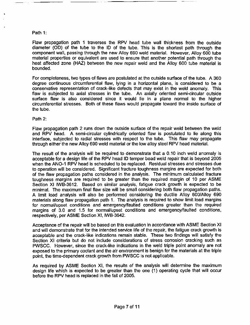
Path 1:
Flaw propagation path 1 traverses the RPV head tube wall thickness from the outsidediameter (OD) of the tube to the ID of the tube. This is the shortest path through thecomponent wall, passing through the new Alloy 690 weld material. However, Alloy 600 tubematerial properties or equivalent are used to ensure that another potential path through theheat affected zone (HAZ) between the new repair weld and the Alloy 600 tube material isbounded.
For completeness, two types of flaws are postulated at the outside surface of the tube. A 360degree continuous circumferential flaw, lying in a horizontal plane, is considered to be aconservative representation of crack-like defects that may exist in the weld anomaly. Thisflaw is subjected to axial stresses in the tube. An axially oriented semi-circular outsidesurface flaw is also considered since it would lie in a plane normal to the highercircumferential stresses. Both of these flaws would propagate toward the inside surface ofthe tube.
Path 2:
Flaw propagation path 2 runs down the outside surface of the repair weld between the weldand RPV head. A semi-circular cylindrically oriented flaw is postulated to lie along thisinterface, subjected to radial stresses with respect to the tube. This flaw may propagatethrough either the new Alloy 690 weld material or the low alloy steel RPV head material.
The result of the analysis will be required to demonstrate that a 0.10 inch weld anomaly isacceptable for a design life of the RPV head ID temper bead weld repair that is beyond 2005when the ANO-1 RPV head is scheduled to be replaced. Residual stresses and stresses dueto operation will be considered. Significant fracture toughness margins are expected for bothof the flaw propagation paths considered in the analysis. The minimum calculated fracturetoughness margins are required to be greater than the required margin of 10 per ASMESection Xl IWB-3612. Based on similar analysis, fatigue crack growth is expected to beminimal. The maximum final flaw size will be small considering both flaw propagation paths.A limit load analysis will also be performed considering the ductile Alloy 600/Alloy 690materials along flaw propagation path 1. The analysis is required to show limit load marginsfor normal/upset conditions and emergency/faulted conditions greater than the requiredmargins of 3.0 and 1.5 for normal/upset conditions and emergency/faulted conditions,respectively, per ASME Section Xl, IWB-3642.
Acceptance of the repair will be based on this evaluation in accordance with ASME Section Xland will demonstrate that for the intended service life of the repair, the fatigue crack growth isacceptable and the crack-like indications remain stable. These two findings will satisfy theSection Xl criteria but do not include considerations of stress corrosion cracking such asPWSCC. However, since the crack-like indications in the weld triple point anomaly are notexposed to the primary coolant and the air environment is benign for the materials at the triplepoint, the time-dependent crack growth from PWSCC is not applicable.
As required by ASME Section Xl, the results of the analysis will determine the maximumdesign life which is expected to be greater than the one (1) operating cycle that will occurbefore the RPV head is replaced in the fall of 2005.
Page 7 of 11
For the reasons described above, areas of J-welds containing flaws accepted by analyticalevaluation will not be reexamined as required by IWB-3142.4. Although solidificationanomalies may occur in the new repair weld, volumetric examination of these welds during asubsequent refueling outage is not required since Entergy plans to replace the ANO-1 RPVhead during 1 RI 9. (1 RI 9 is scheduled to begin during the fall of 2005.)
Justification for Proposed Alternative:
Removal of the cracks in the existing J-groove partial penetration welds would incurexcessive radiation dose for repair personnel. With the installation of the new pressureboundary welds previously described, the original function of the J-groove partial penetrationwelds is no longer required. It is well understood that the cause of the cracks in the subjectJ-groove welds is PWSCC. As shown by industry experience, the low alloy steel of the RPVhead impedes crack growth by PWSCC. Entergy believes the altemative will provide anacceptable level of quality and safety when compared to the code requirements in IWB-3500to characterize the cracks left in service. Using flaw tolerance techniques and an assumedworst-case crack size, the analysis will be required to demonstrate that unacceptable flawgrowth into the RPV head does not occur within the next operating cycle. Thus, the RPVhead can be accepted per the requirements of IWA-4310.
Based on extensive industry experience and Framatome-ANP direct experience, there are noknown cases where flaws initiating in an Alloy 82/182 weld have propagated into the ferriticbase material. The surface examinations performed associated with flaw removal duringrecent repairs at Oconee 1 and 3 on RPV head penetrations, Catawba 2 steam generatorchannel head drain connection penetration, ANO-1 hot leg level tap penetrations and the VCSummer Hot Leg pipe to primary outlet nozzle repair (reference MRP-44: Part : Alloy 82/182Pipe Butt Welds, EPRI, 2001. TP-1001491) all support the assumption that the flaws wouldblunt at the interface of the Ni-Cr-Fe weld to ferritic base material. Additionally, the SmallDiameter Alloy 600/690 Nozzle Repair Replacement Program (CE NPSD-1 198-P) providesdata that shows PWSCC does not occur in ferritic pressure vessel steel. Based on industryexperience and operation stress levels, there is no reason for service related cracks topropagate into the ferritic material from the Alloy 82/182 weld.
Elimination of the weld triple point anomaly would require use of an entirely different processthan that proposed for use on ANO-1. The only qualified method currently available wouldinvolve extensive manual welding that would result in radiation doses estimated to be inexcess of 30 REM per nozzle as compared to the 5 REM estimated for each nozzle repairedby the proposed process.
Compliance with the specified Code requirements would result in excessive radiationexposure: a hardship or unusual difficulty without a compensating increase in the level ofquality and safety.
V. Duration of the Proposed Alternative
Entergy plans to replace the ANO-1 RPV head during Refueling Outage 1R19, which isscheduled to begin during the fall of 2005. Therefore, this request will be limited to oneoperating cycle.
Page 8 of 11
A Framatome-ANP evaluation will be performed to determine the time for a postulated crackto grow 75% through-wall in the Alloy 600 nozzle material above the repair weld. Theevaluation will consider RPV head nozzles in the as-repaired condition and will encompassinitiation and crack growth due to primary water stress corrosion cracking (PWSCC). With noapplication of abrasive water jet (AWJ) remediation, Entergy has estimated 2.5 effective fullpower years (EFPY) for a crack to grow 75% through-wall. Since Entergy plans to replacethe ANO-1 RPV head prior to the end of service life (2.5 EFPY), AWJ remediation is notnecessary.
Flaw growth rates for evaluation will be assumed to follow the 4 mm/year rate, which boundsany variation in flaw growth through the Alloy 600 material as a result of the weld repair.
Given these expected results, the proposed inspection schedules given above, and theplanned replacement date for the ANO-1 RPV head, Entergy believes the proposedaltematives to the ASME Code requirements are justified. The proposed alternatives areapplicable to the repairs and examinations after repair to any ANO-1 RPV head nozzle.
VI. Implementation Schedule
This request will be implemented during upcoming refueling outage 1 R18, which is scheduledto begin during the second quarter of 2004. Entergy plans to replace the ANO-1 RPV headduring Refueling Outage 1 RI 9, which is scheduled to begin during the fall of 2005.
Page 9 of 11
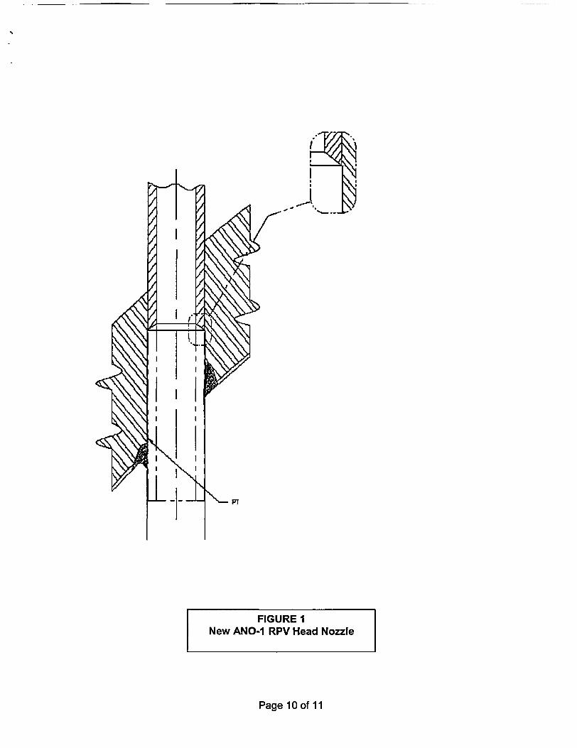
Page 10 of 11
..,
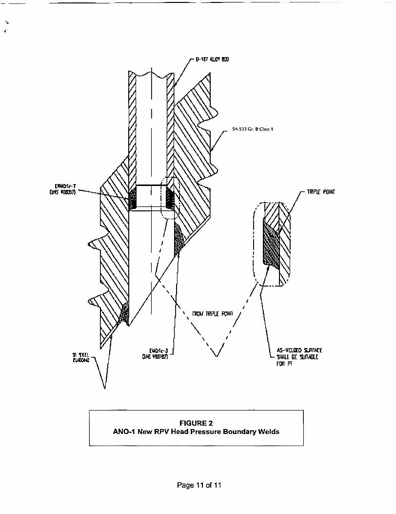
ERA!rK-7
(DN NOW EI
Si 91EELwLWC
SA-533 Gr. B Class 1
1ZP[E POrT
I
LI
I
A5-W[LCED SRFArEs* R TE SnABLEFOR PT
Page 11 of 11
FIGURE 2ANO-1 New RPV Head Pressure Boundary Welds
* E 1 7 kO DM
j.