Embed Size (px)
Citation preview
INEEL/EXT-03-00976
U.S. Department of Energy
FreedomCAR & Vehicle Technologies Program Advanced Vehicle Testing Activity
Arizona Public Service – Alternative Fuel (Hydrogen) Pilot Plant Design Report
TECHNICAL REPORT
Don Karner
James Francfort
December 2003
Idaho National Engineering and Environmental Laboratory Bechtel BWXT Idaho, LLC
INEEL/EXT–03–00976
U.S. Department of Energy FreedomCAR & Vehicle Technologies Program
Advanced Vehicle Testing Activity
Arizona Public Service - Alternative Fuel
(Hydrogen) Pilot Plant Design Report
Don Karner James Francfort
December 2003
Idaho National Engineering and Environmental Laboratory Transportation Technology and Infrastructure Department
Idaho Falls, Idaho 83415
Prepared for the U.S. Department of Energy
Assistant Secretary for Energy Efficiency and Renewable Energy Under DOE Idaho Operations Office
Contract DE-AC07-99ID13727
Disclaimer This document highlights work sponsored by agencies of the U.S. Government. Neither the U.S. Government nor any agency thereof, nor any of their employees, makes any warranty, express or implied, or assumes any legal liability or responsibility for the accuracy, completeness, or usefulness of any information, apparatus, product, or process disclosed, or represents that its use would not infringe privately owned rights. Reference herein to any specific commercial product, process, or service by trade name, trademark, manufacturer, or otherwise does not necessarily constitute or imply its endorsement, recommendation, or favoring by the U.S. Government or any agency thereof. The views and opinions of authors expressed herein do not necessarily state or reflect those of the U.S. Government or any agency thereof.
CONTENTS
1. INTRODCUTION.............................................................................................................................. 1 1.1 Objectives................................................................................................................................. 1 1.2 Background .............................................................................................................................. 1 1.3 Siting the Fueling Station......................................................................................................... 2
1.3.1 Site Description ............................................................................................................. 2 1.3.2 Siting Process ................................................................................................................ 3 1.3.3 Permits ........................................................................................................................... 4
1.4 Fueling Station Design............................................................................................................. 4 2. HYDROGEN SYSTEM..................................................................................................................... 6
2.1 Design Criteria ......................................................................................................................... 6 2.2 Water Purification .................................................................................................................... 8 2.3 Hydrogen Production ............................................................................................................... 8 2.4 Dryer and Filters ...................................................................................................................... 9 2.5 Low-Pressure Storage ............................................................................................................ 11 2.6 Hydrogen Compressor ........................................................................................................... 12 2.7 Hydrogen High-Pressure Storage........................................................................................... 13 2.8 Fuel Dispensing...................................................................................................................... 14 2.9 Emergency Shutdown System – EMS ................................................................................... 15 2.10 Auxiliary Systems .................................................................................................................. 16
2.10.1 Control Air................................................................................................................... 16 2.10.2 Chiller .......................................................................................................................... 16 2.10.3 Nitrogen ....................................................................................................................... 17 2.10.4 Vacuum........................................................................................................................ 17
2.11 Drains, Vents, Tubing, Vent Stack, and Blowdown Tank ..................................................... 17 2.12 Hydrogen System Valves....................................................................................................... 18 2.13 Control and Instrumentation .................................................................................................. 20 2.14 Electrical ................................................................................................................................ 21 2.15 Color Coding of Fluid Lines .................................................................................................. 21 2.16 Helium and Fire Sprinkler System......................................................................................... 22 2.17 Flame and Flammable Gas Detection .................................................................................... 22
3. COMPRESSED NATURAL GAS SYSTEM .................................................................................. 23 3.1 Fueling Station Overview ...................................................................................................... 23 3.2 CNG System Design Criteria ................................................................................................. 23 3.3 Low-Pressure Storage ............................................................................................................ 25 3.4 Medium-Pressure Storage ...................................................................................................... 26
i
3.5 High-Pressure Storage............................................................................................................ 26 3.6 Storage Filling........................................................................................................................ 26
3.6.1 Hand Control ............................................................................................................... 27 3.6.2 Automatic Control ....................................................................................................... 27
3.7 Fuel Dispensing...................................................................................................................... 27 3.8 Emergency Shutdown System................................................................................................ 28
3.8.1 Emergency Shutdown System Initiation ..................................................................... 28 3.8.2 Emergency Shutdown System Automatic Actuations ................................................. 28
3.9 CNG System Valves .............................................................................................................. 29 3.10 Compressed Natural Gas System Filters................................................................................ 33 3.11 Control and Instrumentation .................................................................................................. 33
4. FUEL DISPENSING........................................................................................................................ 38 4.1 Refueling Equipment at the 501 Facility ............................................................................... 38
4.1.1 Existing Liquid Refueling Systems ............................................................................. 38 4.1.2 Existing Electric Refueling Systems ........................................................................... 38 4.1.3 New Gaseous Refueling .............................................................................................. 39
4.2 Fuel Dispensing System Description ..................................................................................... 40 4.2.1 Hydrogen Dispenser Operation ................................................................................... 41 4.2.2 CNG Dispenser Operation........................................................................................... 41
5. LESSIONS LEARNED.................................................................................................................... 42 5.1 Codes And Standards ............................................................................................................. 42 5.2 Facility Layout ....................................................................................................................... 42 5.3 Piping ..................................................................................................................................... 42 5.4 Electrical Grounding .............................................................................................................. 42 5.5 Construction ........................................................................................................................... 43 5.6 Fuel Dispensing...................................................................................................................... 43
6. LIST OF APPENDICES .................................................................................................................. 44
ii
ACRONYMS
AOV air-operated valve
APS Arizona Public Service
BIT built-in test
CNG compressed natural gas
DCS dispenser control system
DI deionized (water)
EMS emergency shutdown system
ESD emergency shutdown
GGE gasoline gallon equivalent
HCNG hydrogen enriched compressed natural gas
HPS high-pressure storage
ID inside diameter
INEEL Idaho National Engineering and Environmental Laboratory
IR infrared
LFL lower flammability limit
LPS low-pressure storage
MAWP maximum allowable working pressure
NFPA National Fire Protection Association
OD outside diameter
Pdc Pdc Machines, Inc.
PLC programmable logic controller
psi pounds per square inch
psid Pounds per square inch, differential
RO reverse osmosis
scf standard cubic feet
scfh standard cubic feet per hour
UV ultraviolet
iii
1. INTRODCUTION
Hydrogen has promise to be the fuel of the future. Its use as a chemical reagent and as a rocket propellant has grown to over eight million metric tons per year in the United States. Although use of hydrogen is abundant, it has not been used extensively as a transportation fuel. To assess the viability of hydrogen as a transportation fuel and the viability of producing hydrogen using off-peak electric energy, Pinnacle West Capital Corporation (PNW) and its electric utility subsidiary, Arizona Public Service (APS) designed, constructed, and operates a hydrogen and compressed natural gas fueling station—the APS Alternative Fuel Pilot Plant. This report summarizes the design of the APS Alternative Fuel Pilot Plant and presents lessons learned from its design and construction. Electric Transportation Applications prepared this report under contract to the U.S. Department of Energy’s Advanced Vehicle Testing Activity. The Idaho National Engineering and Environmental Laboratory manages these activities for the Advanced Vehicle Testing Activity.
1.1 Objectives The objectives of constructing and operating the Alternative Fuel Pilot Plant have been to:
1. Ascertain the safety issues for a hydrogen production operation in a commercial setting
2. Evaluate the adequacy of existing codes, standards, regulations, and recommended practices within a commercial setting
3. Establish models for future codes and standards for distributed hydrogen generation systems within a commercial setting
4. Determine performance limitations of existing technologies and components
5. Evaluate the practicality of the systems in a commercial facility
6. Evaluate hydrogen and blended CNG/hydrogen as a potential fuel for internal combustion engines
7. Develop a working model of a refueling system for fuel-cell electric vehicles and internal combustion engine vehicles.
1.2 Background Several stored forms of hydrogen could be considered for use as a transportation fuel: gas, liquid,
slush, and metal hydrides. Two common methods of producing hydrogen are reforming of hydrocarbons such as methane and methanol, and electrolysis of water. Reforming of hydrocarbons, although today the most common and economical way of hydrogen production, results in carbon dioxide (a greenhouse gas) as a byproduct. Electrolysis of water produces only hydrogen and oxygen and is of interest to an electric utility company as a means of improving its load factor and increasing energy sales. In contrast to centralized manufacturing of hydrogen and use of tube trailers for delivery (as in gasoline distribution), the electrolysis process can be used with the existing electric distribution system to produce relatively small quantities of hydrogen during off-peak periods at the point of use. This provides the advantage of leveling electric energy usage and eliminating the need for tube trailer transportation.
Due to the very small number of hydrogen refueling stations, there are limited standards for their construction. Five other commercial hydrogen vehicle-refueling stations have been built in the United States: Sun Line Transit in Palm Springs, California; Ford Proving Ground in Dearborn, Michigan; California Fuel Cell Partnership in Sacramento, California; Las Vegas Transit in Las Vegas, Nevada; and the Honda Proving Ground in Torrance, California. Commercial hydrogen refueling stations have also been built in Germany and Iceland.
1
Due to the limited standards for the construction of hydrogen refueling stations, fueling station designers must rely on existing compressed gas industry standards and portions of existing building codes, while working very closely with local building inspection and safety departments as well as engineering experts with hydrogen experience. The viability of hydrogen as a transportation fuel depends on the speed and ease of working with local building inspectors, and on the costs associated with compliance to existing codes and standards governing fueling station construction.
1.3 Siting the Fueling Station PNW and APS chose to construct the APS Alternative Fuel Pilot Plant in an urban setting to
determine the full impact of existing codes and standards as well as building inspector requirements on station design and on the siting process. This approach is unique to fueling station design in the United States and provides unique insight into the requirements for hydrogen fueling stations to be constructed and operated in commercial, rather than industrial, areas.
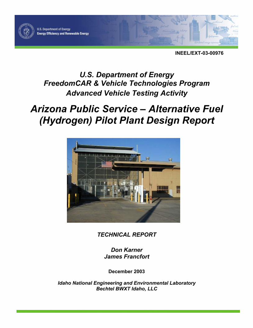
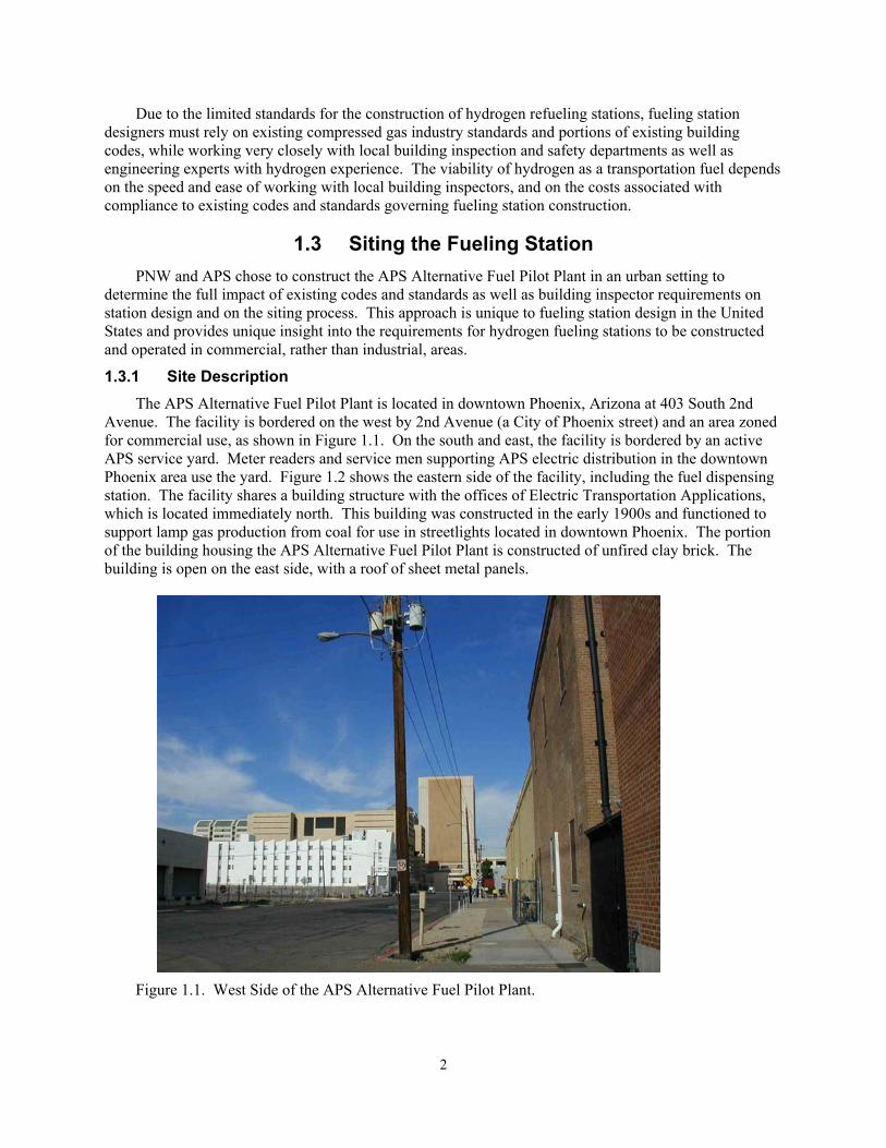
1.3.1 Site Description The APS Alternative Fuel Pilot Plant is located in downtown Phoenix, Arizona at 403 South 2nd
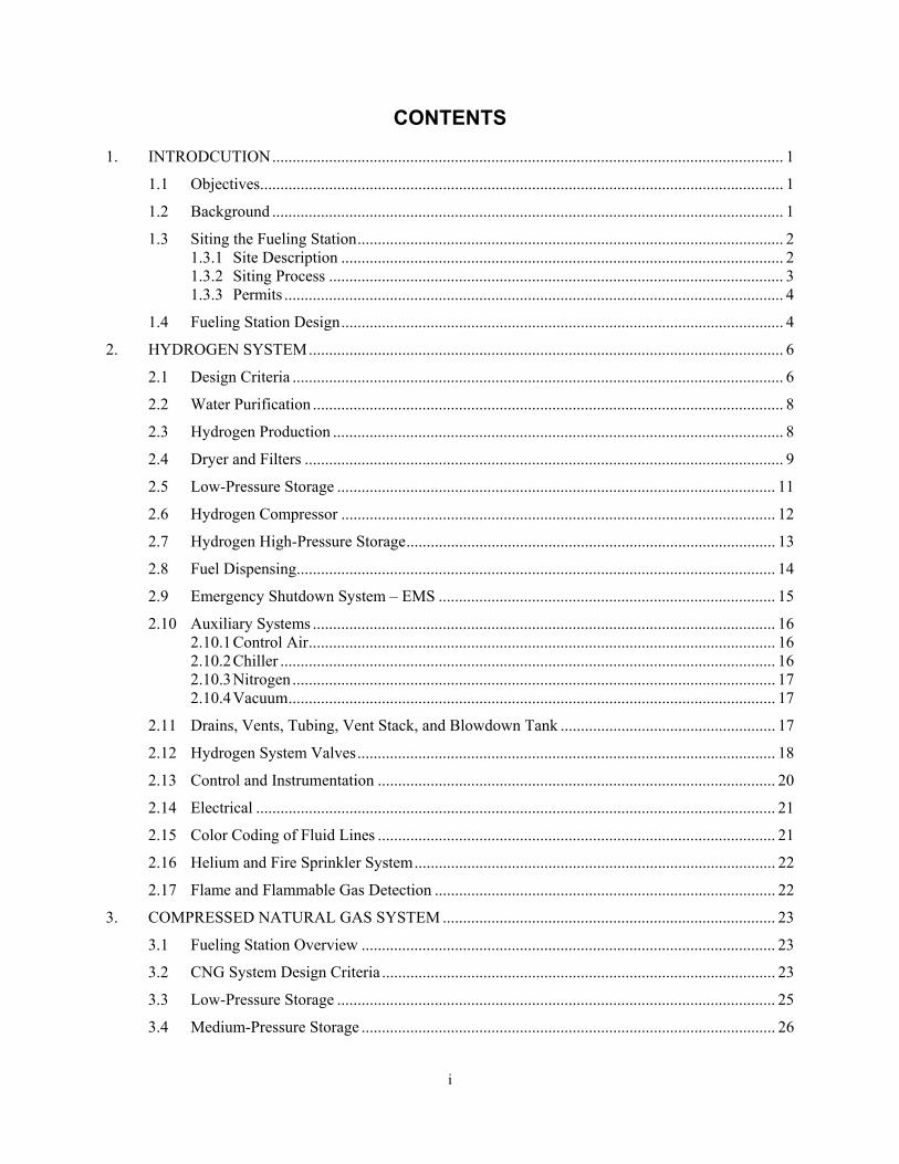
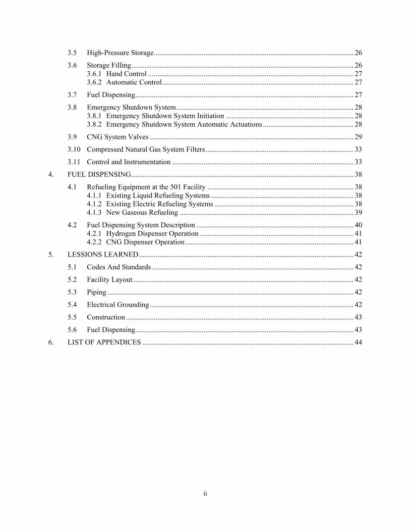
Avenue. The facility is bordered on the west by 2nd Avenue (a City of Phoenix street) and an area zoned for commercial use, as shown in Figure 1.1. On the south and east, the facility is bordered by an active APS service yard. Meter readers and service men supporting APS electric distribution in the downtown Phoenix area use the yard. Figure 1.2 shows the eastern side of the facility, including the fuel dispensing station. The facility shares a building structure with the offices of Electric Transportation Applications, which is located immediately north. This building was constructed in the early 1900s and functioned to support lamp gas production from coal for use in streetlights located in downtown Phoenix. The portion of the building housing the APS Alternative Fuel Pilot Plant is constructed of unfired clay brick. The building is open on the east side, with a roof of sheet metal panels.
Figure 1.1. West Side of the APS Alternative Fuel Pilot Plant.
2
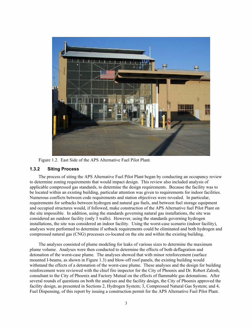
Figure 1.2. East Side of the APS Alternative Fuel Pilot Plant.
1.3.2 Siting Process The process of siting the APS Alternative Fuel Pilot Plant began by conducting an occupancy review
to determine zoning requirements that would impact design. This review also included analysis of applicable compressed gas standards, to determine the design requirements. Because the facility was to be located within an existing building, particular attention was given to requirements for indoor facilities. Numerous conflicts between code requirements and station objectives were revealed. In particular, requirements for setbacks between hydrogen and natural gas fuels, and between fuel storage equipment and occupied structures would, if followed, make construction of the APS Alternative fuel Pilot Plant on the site impossible. In addition, using the standards governing natural gas installations, the site was considered an outdoor facility (only 3 walls). However, using the standards governing hydrogen installations, the site was considered an indoor facility. Using the worst-case scenario (indoor facility), analyses were performed to determine if setback requirements could be eliminated and both hydrogen and compressed natural gas (CNG) processes co-located on the site and within the existing building.
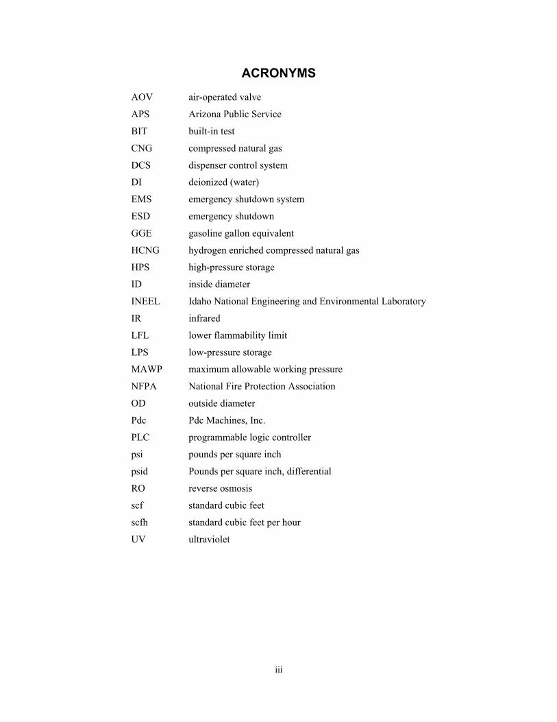
The analyses consisted of plume modeling for leaks of various sizes to determine the maximum plume volume. Analyses were then conducted to determine the effects of both deflagration and detonation of the worst-case plume. The analyses showed that with minor reinforcement (surface mounted I-beams, as shown in Figure 1.3) and blow-off roof panels, the existing building would withstand the effects of a detonation of the worst-case plume. These analyses and the design for building reinforcement were reviewed with the chief fire inspector for the City of Phoenix and Dr. Robert Zalosh, consultant to the City of Phoenix and Factory Mutual on the effects of flammable gas detonations. After several rounds of questions on both the analyses and the facility design, the City of Phoenix approved the facility design, as presented in Sections 2, Hydrogen System; 3, Compressed Natural Gas System; and 4, Fuel Dispensing, of this report by issuing a construction permit for the APS Alternative Fuel Pilot Plant.
3
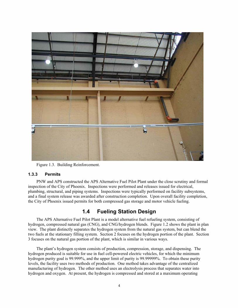
Figure 1.3. Building Reinforcement.
1.3.3 Permits PNW and APS constructed the APS Alternative Fuel Pilot Plant under the close scrutiny and formal
inspection of the City of Phoenix. Inspections were performed and releases issued for electrical, plumbing, structural, and piping systems. Inspections were typically performed on facility subsystems, and a final system release was awarded after construction completion. Upon overall facility completion, the City of Phoenix issued permits for both compressed gas storage and motor vehicle fueling.
1.4 Fueling Station Design The APS Alternative Fuel Pilot Plant is a model alternative fuel refueling system, consisting of
hydrogen, compressed natural gas (CNG), and CNG/hydrogen blends. Figure 1.2 shows the plant in plan view. The plant distinctly separates the hydrogen system from the natural gas system, but can blend the two fuels at the stationary filling system. Section 2 focuses on the hydrogen portion of the plant. Section 3 focuses on the natural gas portion of the plant, which is similar in various ways.
The plant’s hydrogen system consists of production, compression, storage, and dispensing. The hydrogen produced is suitable for use in fuel cell-powered electric vehicles, for which the minimum hydrogen purity goal is 99.999%, and the upper limit of purity is 99.99999%. To obtain these purity levels, the facility uses two methods of production. One method takes advantage of the centralized manufacturing of hydrogen. The other method uses an electrolysis process that separates water into hydrogen and oxygen. At present, the hydrogen is compressed and stored at a maximum operating
4

working pressure of 5,800 psi. The facility has over 17,000 scf of high-pressure storage capacity. The stationary filling system can dispense hydrogen at various pressures, up to the 5,800 psi maximum.
In addition to producing hydrogen, the plant also compresses natural gas for use as a motor fuel. CNG vehicles typically require 3,600 psi storage tanks. However, to fill vehicle onboard tanks, storage pressures must be higher. The APS system compresses natural gas to pressures up to 5,000 psi, using a three-stage cascade pressure arrangement.
5
2. HYDROGEN SYSTEM
2.1 Design Criteria The hydrogen system has six primary functions: water purification, production, compression,
storage, dispensing, and venting. Hydrogen is produced from high-purity water using electrolysis, which is compressed up to 5800 psi and stored in high-pressure-rated vessels. The high-pressure vessels supply the hydrogen to an automated refueling location where it is conveniently dispensed. Figure A-3 of Appendix A presents a plan view of the equipment locations for the hydrogen system. Figure A-2 presents a three-dimensional view of the hydrogen system components.
The electrolysis production process is a crucial element of the facility (see Section 2.3). Appendix B contains a Material Safety Data Sheet for hydrogen. The electrolysis equipment used at the facility is a HOGEN 300, manufactured by Proton Energy Systems. It produces 300 scf of hydrogen per hour at 150 psi, using high-purity water. The water purification process is one of the primary functions of the facility and significantly influences the purity level of the hydrogen within the system (see Section 2.2). The output of the electrolysis equipment is directed to the low-pressure storage vessel (see Section 2.5), which has a storage capacity of 8,955 scf of hydrogen. This vessel provides capacity when the hydrogen generator is not operating.
The pressure rating of the hydrogen generator and the low-pressure storage vessel is 150 psi. In order to provide the desirable dispensing pressures, a three-stage diaphragm compressor is used (see Section 2.6). The compressor is capable of compressing the hydrogen up to 6,000 psi at a rate of 300 scfh. At present, the high-pressure hydrogen system is regulated to 5,800 psi. The normal pipeline from the compressor output fills two high-pressure storage vessels (see Section 2.7). These vessels have a combined storage capacity of 17,386 scf and provide hydrogen for dispensing. The other pipeline from the compressor output provides hydrogen directly to the dispensers.
The capacities of all the storage vessels, the rate of hydrogen production, and the rate of compression can all be coordinated to achieve the required refueling demand. Though only a small mass of hydrogen is produced daily, the system offers model opportunity to evaluate system reliability, cost, and safety, and is a source of fuel for both fuel-cell and combustion engine testing.
The hydrogen system is a completely sealed, closed system. Specifications for hydrogen piping are presented in Appendix C. Proper piping design ensures that hydrogen is not inadvertently released. However, should a hydrogen leak occur, hydrogen gas detectors will signal an alarm and isolate the hydrogen system (see Section 2.9) with automatic shutdown of power to operating equipment (but control power, monitoring systems, and communication system remain energized).
Any venting or draining of the system is to the vent stack, where hydrogen is released above the roofline of the gas building (see Section 2.11). Design of the system eliminates any direct human contact with hydrogen. A helium purge is available to inert the vent stack (see Section 2.16). To quench fires in hydrogen vents is standard practice in the industry.
A nitrogen purge is used as an intermediary in any event that requires opening of the hydrogen system (see Section 2.10). Nitrogen purge points have been strategically designed into the system to adequately provide for safe operation and maintenance measures.
Because hydrogen fires are invisible, the entire equipment room containing the hydrogen system (see Appendix A, Figure A-3) is a controlled area, accessible only to those who are trained and certified to work around hydrogen systems. Arizona Public Service safety programs and procedures, defined in the
6
APS Safety Manual, have been applied to the pilot plant. Training programs prepared for the APS Alternative Fuel Pilot Plant are presented in Appendix D.
The gas building is continuously scanned for infrared and ultraviolet radiation, both typical signatures of a hydrogen flame (see Section 2.17). Combustible gas monitors are also used to monitor for hydrogen in the work area (see Section 2.17). These monitors will alarm at 25% LFL (lower flammability limit) of hydrogen. Equipment has been well grounded to eliminate static electricity as an ignition source (see Section 2.14). Hydrogen, unlike most fluids, does not build up a static charge when flowing; however, particles flowing in the hydrogen stream can create adequate energy to ignite the hydrogen if sufficient oxygen is present.
The EMS (emergency shutdown system) enables complete system shutdown, automatically or manually initiated (see Section 2.9). EMS alarm and annunciation visually and audibly indicate that the EMS has been initiated. If the hydrogen system isolation is breached, as detected by IR (infra-red) and UV (ultraviolet) scanners, gas detectors, or human intervention, the second contingency of isolation is automatically initiated by isolating all hydrogen storage, hydrogen production, and hydrogen dispensing; and by shutting off the power supply to the HOGEN 300 generator, dryer, and compressor.
Under the City of Phoenix ordinances, production of hydrogen gas must be performed in an area zoned A1, whereas retail sale of hydrogen gas can be in areas zoned C3. National Fire Protection Code (NFPA) 50A presents standards for constructing a hydrogen storage facility, but the code does not apply to hydrogen production facilities, per NFPA 50A, 1-3.3. The hydrogen production, compression, and storage equipment is physically located within the gas equipment building, while the water purification equipment, cooling equipment, nitrogen equipment, air compressor, and electrical panels are located in an adjacent room. The hydrogen electrical system within the gas building is engineered as Class 1, Division 2, in accordance with NFPA 70. Storage of hydrogen and related piping/tubing is in accordance with ASME Code B31.3.
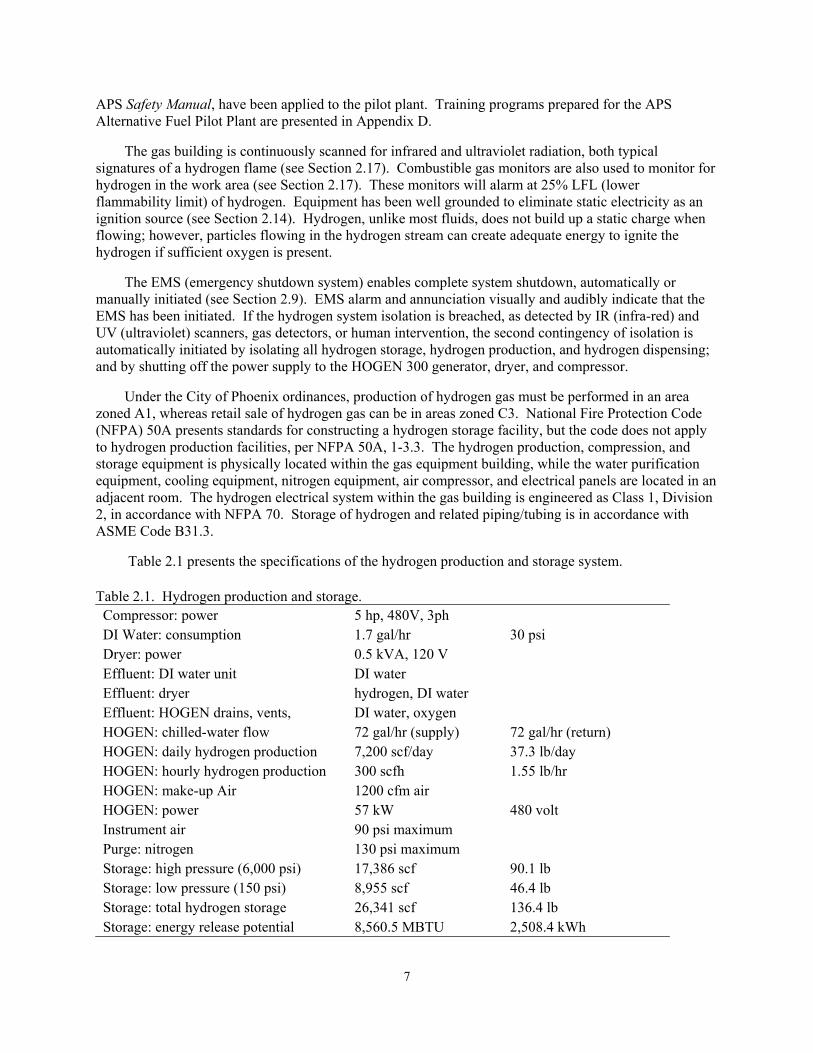
Table 2.1 presents the specifications of the hydrogen production and storage system. Table 2.1. Hydrogen production and storage. Compressor: power 5 hp, 480V, 3ph DI Water: consumption 1.7 gal/hr 30 psi Dryer: power 0.5 kVA, 120 V Effluent: DI water unit DI water Effluent: dryer hydrogen, DI water Effluent: HOGEN drains, vents, DI water, oxygen HOGEN: chilled-water flow 72 gal/hr (supply) 72 gal/hr (return) HOGEN: daily hydrogen production 7,200 scf/day 37.3 lb/day HOGEN: hourly hydrogen production 300 scfh 1.55 lb/hr HOGEN: make-up Air 1200 cfm air HOGEN: power 57 kW 480 volt Instrument air 90 psi maximum Purge: nitrogen 130 psi maximum Storage: high pressure (6,000 psi) 17,386 scf 90.1 lb Storage: low pressure (150 psi) 8,955 scf 46.4 lb Storage: total hydrogen storage 26,341 scf 136.4 lb Storage: energy release potential 8,560.5 MBTU 2,508.4 kWh
7
2.2 Water Purification Potable water is supplied from a Phoenix street potable water supply (30 psi) to a water treatment
system designed and manufactured by CIW Services, Inc. The CIW system has a 5-µ filter, carbon filter, stainless steel pump, reverse osmosis bank, 34-gal storage tank, mixed-bed demineralizer, and a 1.0-µ exit filter specifically built to accommodate Phoenix water. The maximum system flow rate is 215 gal/day.
The CIW system has two effluent lines: one 1” line from the RO (reverse osmosis) unit, and a second ¾” line from the storage tank bleed.
Deionized (DI) water flows to the drain until the minimum quality level is reached, as determined by an analyzer; about 30 gallons of DI water are consumed during startup. Once the water quality threshold has been achieved, the water drain-valve closes, and the supply to the HOGEN opens. During HOGEN shutdown, about 10 gal of DI water is discharged to the drain. A secondary DI water-polishing unit inside the HOGEN further purifies the water and provides backup to the primary DI water system.
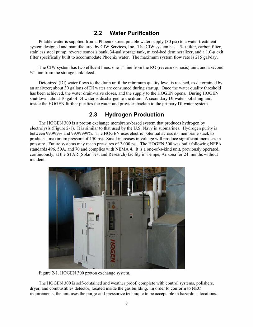
2.3 Hydrogen Production The HOGEN 300 is a proton exchange membrane-based system that produces hydrogen by
electrolysis (Figure 2-1). It is similar to that used by the U.S. Navy in submarines. Hydrogen purity is between 99.999% and 99.99999%. The HOGEN uses electric potential across its membrane stack to produce a maximum pressure of 150 psi. Small increases in voltage will produce significant increases in pressure. Future systems may reach pressures of 2,000 psi. The HOGEN 300 was built following NFPA standards 496, 50A, and 70 and complies with NEMA 4. It is a one-of-a-kind unit, previously operated, continuously, at the STAR (Solar Test and Research) facility in Tempe, Arizona for 24 months without incident.
Figure 2-1. HOGEN 300 proton exchange system.
The HOGEN 300 is self-contained and weather proof, complete with control systems, polishers, dryer, and combustibles detector, located inside the gas building. In order to conform to NEC requirements, the unit uses the purge-and-pressurize technique to be acceptable in hazardous locations.
8
This requires a fresh air purge (from an unclassified area) at the rate of 1,200 scfm. The HOGEN 300 requires a chilled-water cooling system. This system provides cooling to the power electronics in the hydrogen generator. The chilled-water system is a separate unit located outside of the gas building. This closed-loop system has maximum potential to circulate at a rate of 72 gal/hr. A nitrogen purge port is incorporated into the HOGEN (there is no manufacturer’s requirement to use the nitrogen purge for maintenance). The HOGEN needs 57 kW of electricity from a 480-V, 150-A, 3-phase supply, and ground. The electric installation is installed above ground and complies with NFPA 70. Communications allow remote system monitoring, with alarms and emergency shutdown. Table 2.2 describes the interfacing of all support systems for the HOGEN 300.
Table 2.2. HOGEN 300 systems interfacing. Element Required support
Combustible gas mixture detector Master system alarm Condensate drain Blow-down tank and vent system Control air 5 scf daily, 90-psi max pressure, clean dry air Data line Modem accessible Electric power 57 kW (480 V, 150 A) Electrical grounding NFPA 70 Hydrogen vent (startup) To vent stack Local shutdown Master system alarm Oxygen vent 0.5 in. to building roof, min 25 ft from H2 vent Power electronics cooling Chiller outside of gas building Purge air 1,200 scfm, clean outside air Purge nitrogen 0.5 in. manually activated Remote shutdown Emergency shutdown system and alarm
The hydrogen production rate is 300 scfh at 150 psi (8 NM3/hr, 10 bars, 1.56 lb/hr). The HOGEN
requires DI water conductivity better than 1-µ siemen (1MΩ-cm resistivity) and preferably better than 0.1-µS (10MΩ-cm). Water consumption is 1.7 gal/hr (or 6.4 l/hr) at an average supply pressure of 15 to 60 psi. During startup, hydrogen is initially vented to the vent stack until the quality level is achieved, upon which venting terminates. In normal operation, there is no leakage or venting of hydrogen gas. Oxygen is a byproduct of the HOGEN operation. Oxygen is vented to the outside in a separate vent stack at atmospheric pressure (150 scfh, 12.4 lb/hr) from a 0.5-in. connection on the HOGEN unit, through the gas-building roof. The HOGEN comes prepackaged with its own propriety control system.
2.4 Dryer and Filters Hydrogen produced by the HOGEN 300 contains water. Although water contamination is not a
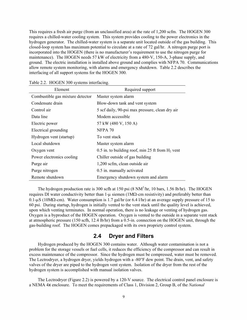
problem for the storage vessels or fuel cells, it reduces the efficiency of the compressor and can result in excess maintenance of the compressor. Since the hydrogen must be compressed, water must be removed. The Lectrodryer, a hydrogen dryer, yields hydrogen with a -80°F dew point. The drain, vent, and safety valves of the dryer are piped to the hydrogen vent system. Isolation of the dryer from the rest of the hydrogen system is accomplished with manual isolation valves.
The Lectrodryer (Figure 2.2) is powered by a 120-V source. The electrical control panel enclosure is a NEMA 4x enclosure. To meet the requirements of Class 1, Division 2, Group B, of the National
9
Electrical Code, the enclosure uses purged nitrogen as a hazardous-location protection technique. Features of the dryer include electric reactivation heaters, thermostatic over-temperature protection, nonlubricated transflow valves, dial thermometer in the reactivation exhaust piping, and reactivation indicator lights.
Figure 2.2. Lectrodryer hydrogen dryer.
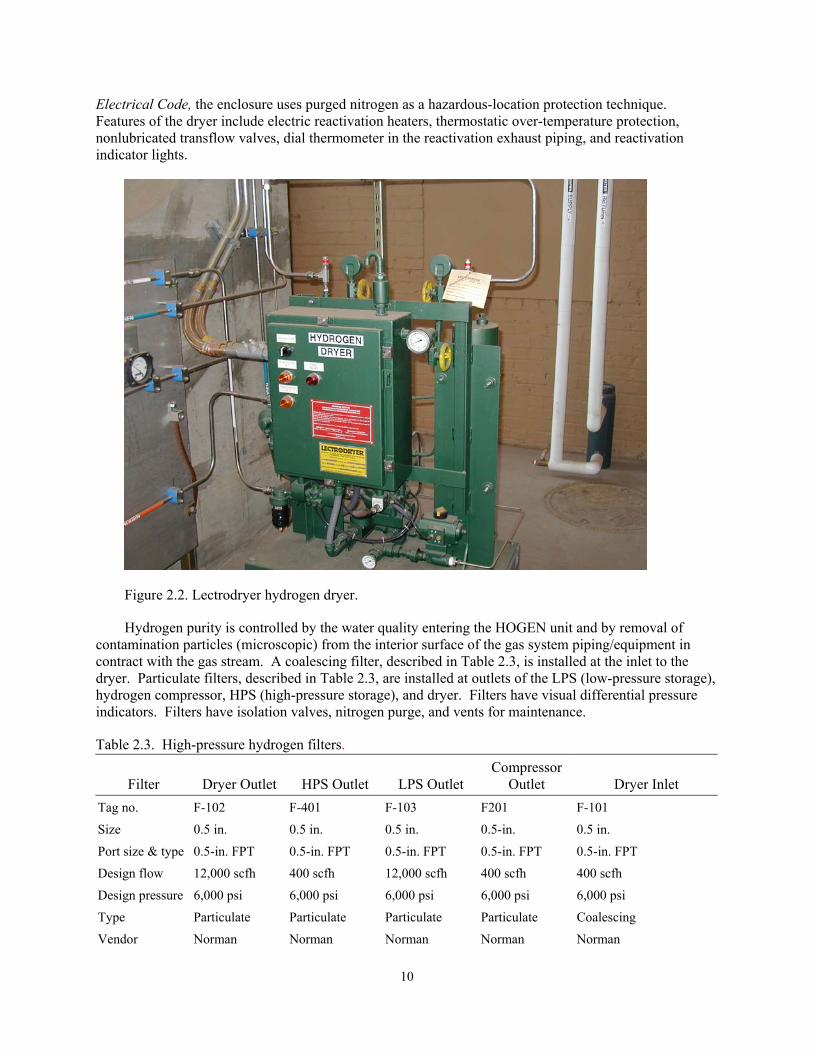
Hydrogen purity is controlled by the water quality entering the HOGEN unit and by removal of contamination particles (microscopic) from the interior surface of the gas system piping/equipment in contract with the gas stream. A coalescing filter, described in Table 2.3, is installed at the inlet to the dryer. Particulate filters, described in Table 2.3, are installed at outlets of the LPS (low-pressure storage), hydrogen compressor, HPS (high-pressure storage), and dryer. Filters have visual differential pressure indicators. Filters have isolation valves, nitrogen purge, and vents for maintenance.
Table 2.3. High-pressure hydrogen filters.
Filter
Dryer Outlet
HPS Outlet
LPS Outlet Compressor
Outlet
Dryer Inlet Tag no. F-102 F-401 F-103 F201 F-101
Size 0.5 in. 0.5 in. 0.5 in. 0.5-in. 0.5 in.
Port size & type 0.5-in. FPT 0.5-in. FPT 0.5-in. FPT 0.5-in. FPT 0.5-in. FPT
Design flow 12,000 scfh 400 scfh 12,000 scfh 400 scfh 400 scfh
Design pressure 6,000 psi 6,000 psi 6,000 psi 6,000 psi 6,000 psi
Type Particulate Particulate Particulate Particulate Coalescing
Vendor Norman Norman Norman Norman Norman
10
Model Tee Type 535 Tee Type 535 Tee Type 535 Tee Type 535 In-line 4200 Series
Part No. 4535TP. 5ABSFNV
4535TP. 5ABSFNV
4535GP. 5ABSFNV
453GP. 5ABSFNV
42.5T-4PP
MAWP 6,000 psi 6,000 psi 6,000 psi 6,000 psi 6,000 psi
Burst pressure 24,000 psi 24,000 psi 24,000 psi 24,000 psi 24,000 psi
Filter rating 0.5-µm, sintered 316 SS
0.5-µm, sintered 316 SS
0.5-µm, sintered 316 SS
0.5-µm, sintered 316 SS
0.5-µm, sintered 316 SS
Temp. rating 800˚F 800˚F 800˚F 800˚F 800˚F
Body material 316 SS 316 SS 303 SS 303 SS 304 SS
Seal material Viton Viton Viton Viton Viton
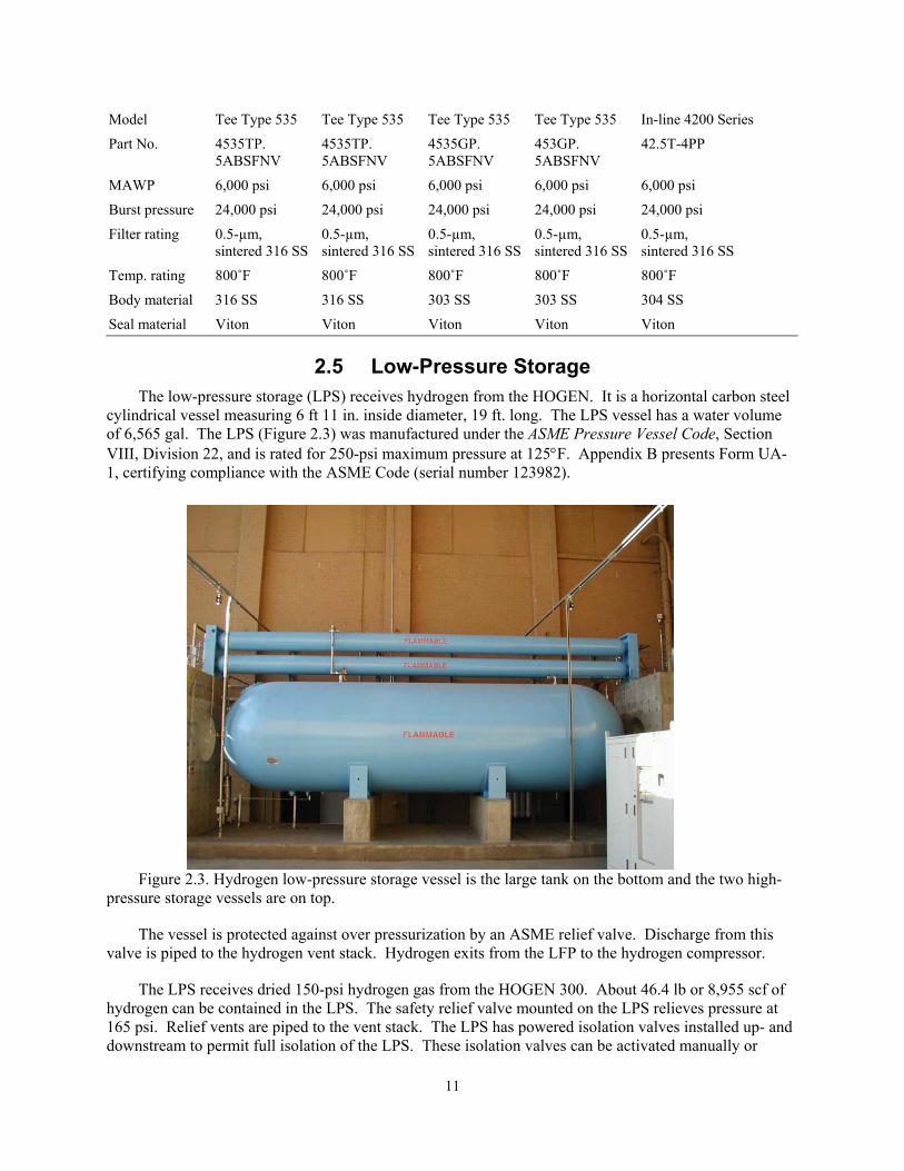
2.5 Low-Pressure Storage The low-pressure storage (LPS) receives hydrogen from the HOGEN. It is a horizontal carbon steel
cylindrical vessel measuring 6 ft 11 in. inside diameter, 19 ft. long. The LPS vessel has a water volume of 6,565 gal. The LPS (Figure 2.3) was manufactured under the ASME Pressure Vessel Code, Section VIII, Division 22, and is rated for 250-psi maximum pressure at 125°F. Appendix B presents Form UA-1, certifying compliance with the ASME Code (serial number 123982).
Figure 2.3. Hydrogen low-pressure storage vessel is the large tank on the bottom and the two high-pressure storage vessels are on top.
The vessel is protected against over pressurization by an ASME relief valve. Discharge from this valve is piped to the hydrogen vent stack. Hydrogen exits from the LFP to the hydrogen compressor.
The LPS receives dried 150-psi hydrogen gas from the HOGEN 300. About 46.4 lb or 8,955 scf of hydrogen can be contained in the LPS. The safety relief valve mounted on the LPS relieves pressure at 165 psi. Relief vents are piped to the vent stack. The LPS has powered isolation valves installed up- and downstream to permit full isolation of the LPS. These isolation valves can be activated manually or
11
automatically by the EMS. Isolation of the LPS includes an activated ball valve (electrically operated) and a manual valve (open in normal operation). The LPS also has two vents: (1) a power-operated vent that discharges to the vent stack and (2) a manually actuated vent for purity control, which has also been piped to the vent stack. A manual drain for water at the low point of the LPS has been piped to the blow-down vent. The LPS is connected to the nitrogen purge system. The nitrogen purge includes isolation valves and check valves to eliminate back flow of hydrogen.
Pressure on the LPS is monitored with a pressure indicator gauge, pressure switch, and with a pressure transmitter for recording data. Should LPS system pressure exceed 165 psi, the HOGEN will ramp down to 130 psi, and then shut down, followed by an alarm. Should the LPS pressure be low, an alarm will be initiated, and the hydrogen compressor will shut down if compressing hydrogen. The moisture level in the gas delivered to the LPS is monitored using a dew point meter.
The LPS is electrically grounded. It is labeled with the fire diamond symbol for hydrogen (blue 0, red 4, yellow 0) and is visible from the building access. In the event of activation of the EMS, the LPS isolation valves will close. After resolving the conditions causing initiation of the EMS, the EMS will be reset, and the LPS isolation valves can be opened and HOGEN production resumed. If for some reason the LPS requires hydrogen dumping, the power vent can be opened and hydrogen will be released to the vent stack. If operation cannot resume, the nitrogen purge system will be activated after the hydrogen is released to vent, and the LPS will be filled with nitrogen.
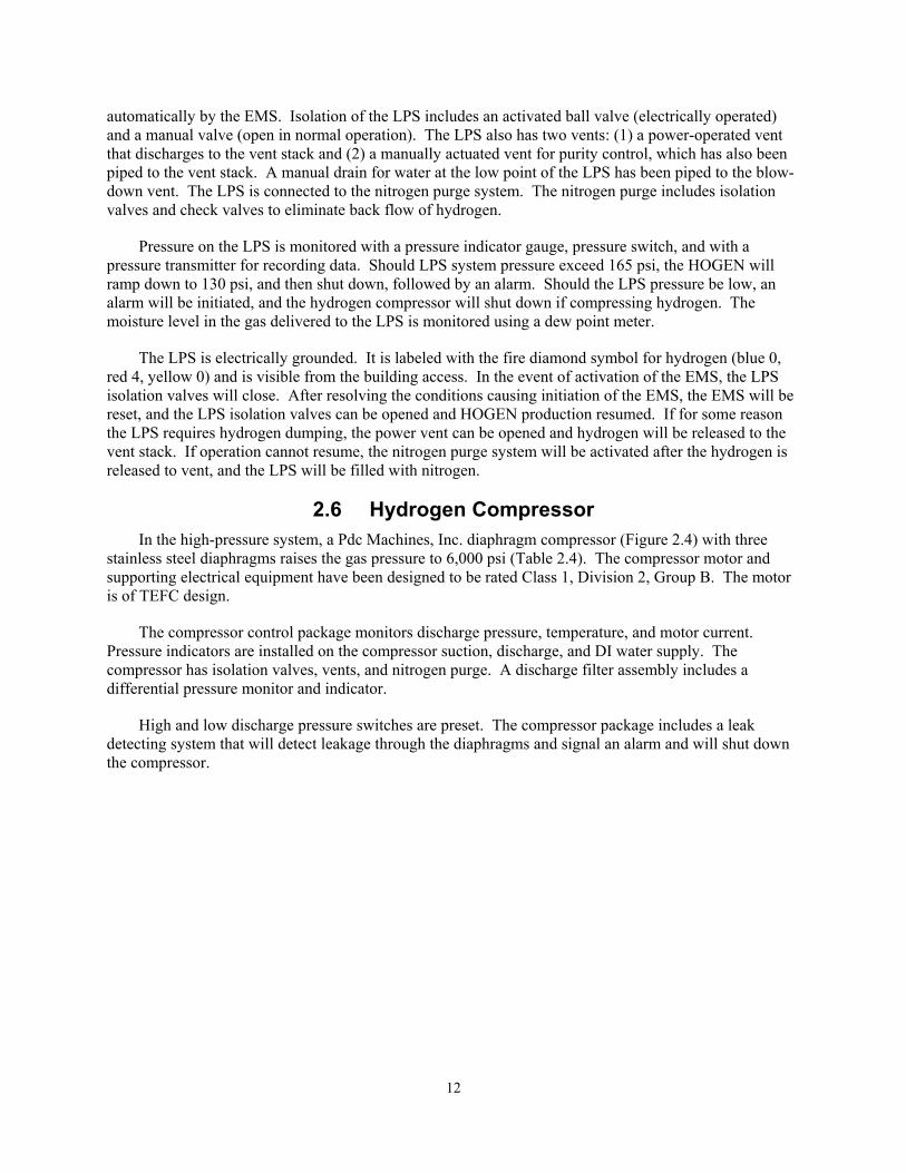
2.6 Hydrogen Compressor In the high-pressure system, a Pdc Machines, Inc. diaphragm compressor (Figure 2.4) with three
stainless steel diaphragms raises the gas pressure to 6,000 psi (Table 2.4). The compressor motor and supporting electrical equipment have been designed to be rated Class 1, Division 2, Group B. The motor is of TEFC design.
The compressor control package monitors discharge pressure, temperature, and motor current. Pressure indicators are installed on the compressor suction, discharge, and DI water supply. The compressor has isolation valves, vents, and nitrogen purge. A discharge filter assembly includes a differential pressure monitor and indicator.
High and low discharge pressure switches are preset. The compressor package includes a leak detecting system that will detect leakage through the diaphragms and signal an alarm and will shut down the compressor.
12
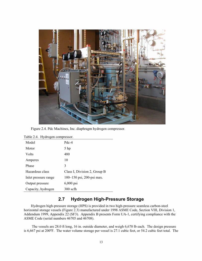
Figure 2.4. Pdc Machines, Inc. diaphragm hydrogen compressor.
Table 2.4. Hydrogen compressor. Model Pdc-4 Motor 5 hp Volts 480 Amperes 10 Phase 3 Hazardous class Class I, Division 2, Group B Inlet pressure range 100–150 psi, 200-psi max. Output pressure 6,000 psi Capacity, hydrogen 300 scfh
2.7 Hydrogen High-Pressure Storage
Hydrogen high-pressure storage (HPS) is provided in two high-pressure seamless carbon-steel horizontal storage vessels (Figure 2.3) manufactured under 1998 ASME Code, Section VIII, Division 1, Addendum 1999, Appendix 22 (SF3). Appendix B presents Form UA-1, certifying compliance with the ASME Code (serial numbers 46705 and 46708).
The vessels are 28.0 ft long, 16 in. outside diameter, and weigh 6,670 lb each. The design pressure is 6,667 psi at 200ºF. The water volume storage per vessel is 27.1 cubic feet, or 54.2 cubic feet total. The
13
operating temperature range of the vessels is -20 to 200ºF. The vessel interiors were steam cleaned after being grit blasted to remove loose scale.
The HPS receives dry 6,000-psi hydrogen gas from the hydrogen compressor. About 90.1 lb, or 17,386 scf, of hydrogen can be contained in the HPS. A safety relief valve mounted to the HPS will relieve pressure at 6,667 psi. The relief valve discharge is piped to the vent stack. The HPS has powered isolation valves installed up- and downstream to permit full isolation of the HPS. These isolation valves can be activated manually or automatically by the EMS. The HPS also has two vents that are piped to the vent stack: (1) a solenoid-operated vent valve piped to the vent stack and (2) a manually operated vent valve for purity control. There is a manual water drain at the low point of the HPS, which is piped to the blow-down vent. The HPS is connected to the nitrogen purge system, which includes isolation and check valves to eliminate backflow of hydrogen.
Pressure on the HPS is monitored with a pressure indicator gauge and with a pressure transmitter for electronic data recording and control. Should the HPS system pressure exceed 6,200 psi, the system will alarm an early warning. If the pressure exceeds 6,300 psi, the EMS will shut down the entire hydrogen system and activate the high-pressure alarm.
The HPS is grounded electrically. The HPS is labeled using the fire diamond symbol for hydrogen (blue 0, red 4, yellow 0) and is visible from the building access. In the event of activation of the EMS, the HPS isolation valves will close. After resolving the conditions causing the initiation of the EMS, the EMS will be reset and the HPS isolation valves can be opened. If for some reason the HPS requires dumping of hydrogen, the power vent can be opened and hydrogen will be released to the vent stack. If operation cannot resume, the nitrogen purge system will be activated after the hydrogen is released to vent, and the HPS will be filled with nitrogen.
There is a 0.5-µ filter in the exit tubing from the HPS and an excess flow control valve and flow switch to detect excess flow, either of which can initiate shutdown of the HPS isolation valves. If tubing or hoses fail downstream of the HPS, the excess flow valve will automatically close. The filter and excess flow valve can be isolated for maintenance.
2.8 Fuel Dispensing The APS Alternative Fuel Pilot Plant has two dual output dispensers (Figure 2.4) manufactured by
Fueling Technologies, Inc. One of these units dispenses CNG only at each output. The other unit has a hydrogen output and a CNG/hydrogen blend output. Dispensers are more fully described in Section 4 of this report.
Appendix E presents hydrogen system and hydrogen dispenser operating procedures.
14

Figure 2.4. CNG only dispenser and hydrogen and CNG/hydrogen blend dispenser.
2.9 Emergency Shutdown System – EMS The EMS is the second-level process control safety system, which reacts after the detected failure of
the primary safety system. The primary safety system for hydrogen is isolation; the second level safety system is shutdown. The following components constitute the system.
• Ultra-fast IR/UV detectors
• Combustible gas detector
• Manual and remote trip
• Vent stack temperature monitor
• Alarms horns and strobe lights
• Calibration and testing of the system
• Vent stack fire suppression.
If a hydrogen event is detected or perceived to have occurred, the EMS will isolate sections of the system and de-energize all operating equipment, including the CNG compressor. Audible alarms and visual lights will notify personnel in the area that activation of the EMS has occurred. An alarm located at the PNW security station at the 502 Building will also indicate that an EMS activation has occurred. Activation of the EMS will be a failsafe action.
15
A hydrogen event is defined as constituting any of the nine items listed below. Any one of the hydrogen events listed will result in activation of audible alarms, strobe lights, and a Security Station alarm. The EMS map will indicate which activation device authorized activation. The EMS will reset itself after a hydrogen event has cleared. • Any of the four IR/UV scanners located in the process area testing positive • The IR/UV scanner located at the fuel-dispensing island testing positive • Manual activation from the fuel-dispensing island. • Manual activation from the east side of the control building • Manual activation from inside the control building • High-pressure switch activated on the LPS vessel. • High-pressure switch activated on the HPS vessels • Flammable gas detects gas leak • Loss of control of air pressure.
The EMS will activate warning strobe lights when in any of the following incidents: • The combustible gas detectors detect 25% of LFL • High temperature is detected on the vent stack. • Incipient flame is detected.
The EMS will provide a process system alarm on any of the following conditions: • Authorization by the vent stack thermocouple to activate helium purge into vent stack • Activation of the excess flow switch • Low-pressure switch activated on hydrogen compressor • Failure of the hydrogen compressor to start • Low-pressure on the vent stack helium system • Compressor leak detected • High pressure detected on LPS • High pressure detected on HPS.
The EMS has a scanner lockout, which permits calibration of the IR/UV scanners without activating the EMS. Negative scan readings should occur within 5 minutes after activation of the EMS. The EMS alarms will be reset, and the system remains down until released for operation by the authorizing engineer. If the IR/UV scanners continue to scan positive after 5 minutes, the authorizing engineer will be contacted.
2.10 Auxiliary Systems 2.10.1 Control Air
The control air system consists of a 100-cfm air compressor, 500-scf storage vessel, and piping network. The control system provides clean dry 90-psi air for the hydrogen system.
2.10.2 Chiller The dual-compressor closed-loop chiller provides 293,000 Btu/h (at 80°F ambient) cooling water to
the HOGEN and Pdc compressor. The Drake model PACT240D unit requires 480 V, 3-phase power, and produces 12 hp at a flow rate of 66 gpm.
16
2.10.3 Nitrogen Nitrogen is used as a buffer gas between the air and hydrogen. The nitrogen system consists of a
production unit, compressor, storage tank, and piping network. Atmospheric air is processed by the nitrogen generator (PSA type system), which produces 97% purity nitrogen. Nitrogen is compressed to 100 psi and stored in a 600-scf vessel. A piping network distributes nitrogen to purge locations on the hydrogen system.
2.10.4 Vacuum During a startup of the hydrogen system, it is necessary to attain the required hydrogen purity, which
consumes a minimum duration of time and hydrogen gas. A portable vacuum pump is used to evacuate the pressure vessels of nitrogen before introduction of hydrogen, to reduce the number of purge cycles in meeting the purity goal.
2.11 Drains, Vents, Tubing, Vent Stack, and Blowdown Tank The system of vents and drains constitutes a significant safety system. The vent stack and blowdown
tank control the release of hydrogen into the atmosphere. It is assumed that once the hydrogen gas reaches the vent stack, or is released from it, it will react with air and burn. Burning could occur in the stack but is most likely to react at the stack exit. Probably, there will be no reaction, but the design assumption is that it will. The reaction of hydrogen with oxygen produces water; hence, in the worst-case scenario there are no environmentally hazardous emissions from the release of hydrogen into the atmosphere. The release is 10 feet above the Gas Building roofline. The design of the vent stack exit prevents nesting of birds or forces of nature blocking the exit of the gas.
The oxygen vent from the HOGEN unit does not go into the vent stack but is routed separately away from the stack. The oxygen vent is fabricated from 0.5-in. 304 stainless steel tubing and is identified as an oxygen vent.
The vent stack begins at the top of the blowdown tank. Drains are piped into the blowdown tank. Vents are piped into the Vent Stack. The blowdown tank is fully open to the vent stack. At the low point of the blowdown tank, a self-closing drain valve permits safe removal of condensate or oil. The vent stack and blowdown tank are normally under atmospheric pressure. The vent stack posts a sign reading “Venting Hydrogen Gas May Ignite.” A helium injection system is installed in the vent stack.
Table 2.5 lists the hydrogen system vents. Vents are fabricated from 0.5-in. 304 stainless steel Swaglock tubing. A 1-in. color-coded tape is used at 5-foot intervals to identify the tubing as a hydrogen system vent line. Flow direction arrows are also mounted on the vent lines. The vent stack utilized weldolets for vent attachment. The blowdown tank has similar attachments for drains. The vent stack is 3-in. schedule 40 stainless steel pipe for the intended duty. The blowdown tank is 6-in. schedule 80 stainless steel pipe. The vent stack is securely anchored to the Gas Building to restrain any thrust from dislodging it, and it is electrically grounded.
Table 2.5. Hydrogen system vents. Vent No. From To Size OV1 HOGEN Top of gas bldg 0.5-in. 304 SS Oxygen vent HV1 HOGEN Vent stack 0.5-in. 304 SS HOGEN vent HV2 Dryer Vent stack 0.5-in. 304 SS Dryer vent HV3 LPS – Powered Vent stack 0.5-in. 304 SS Powered LPS vent HV4 LPS Vent stack 0.5-in. 304 SS Purity LPS vent SRV2 LPS – SRV Vent stack 0.5-in. 304 SS LPS safety relief
17
SRV2 LPS – SRV Vent stack 0.5-in. 304 SS LPS safety relief HV5 F1 Vent stack 0.5-in. 304 SS Filter bleed HV6 H2 Compressor Vent stack 0.5-in. 304 SS Compressor bleed HV7 HPS Vent stack 0.5-in. 304 SS HPS vent HV8 HPS Vent stack 0.5-in. 304 SS HPS vent SRV3 HPS – SRV Vent stack 0.5-in. 304 SS HPS safety relief SRV4 HPS – SRV Vent stack 0.5-in. 304 SS HPS safety relief HV9 Dispenser filter Vent stack 0.5-in. 304 SS Filter bleed HV10 Dispenser vent Vent stack 0.5-in. 304 SS Dispenser nozzle vent
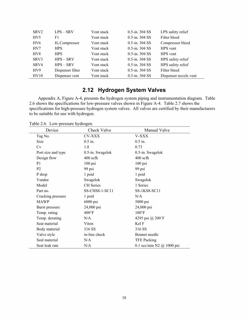
2.12 Hydrogen System Valves Appendix A, Figure A-4, presents the hydrogen system piping and instrumentation diagram. Table
2.6 shows the specifications for low-pressure valves shown in Figure A-4. Table 2.7 shows the specifications for high-pressure hydrogen system valves. All valves are certified by their manufacturers to be suitable for use with hydrogen.
Table 2.6. Low-pressure hydrogen. Device Check Valve Manual Valve
Tag No. CV-XXX V-XXX Size 0.5 in. 0.5 in. Cv 1.8 0.73 Port size and type 0.5-in. Swagelok 0.5-in. Swagelok Design flow 400 scfh 400 scfh P1 100 psi 100 psi P2 99 psi 99 psi P drop 1 psid 1 psid Vendor Swagelok Swagelok Model CH Series 1 Series Part no. SS-CHS8-1-SC11 SS-1KS8-SC11 Cracking pressure 1 psid N/A MAWP 6000 psi 5000 psi Burst pressure 24,000 psi 24,000 psi Temp. rating 400°F 100°F Temp. derating N/A 4295 psi @ 200˚F Seat material Viton Kel F Body material 316 SS 316 SS Valve style in-line check Bonnet needle Seal material N/A TFE Packing Seat leak rate N/A 0.1 scc/min N2 @ 1000 psi
18
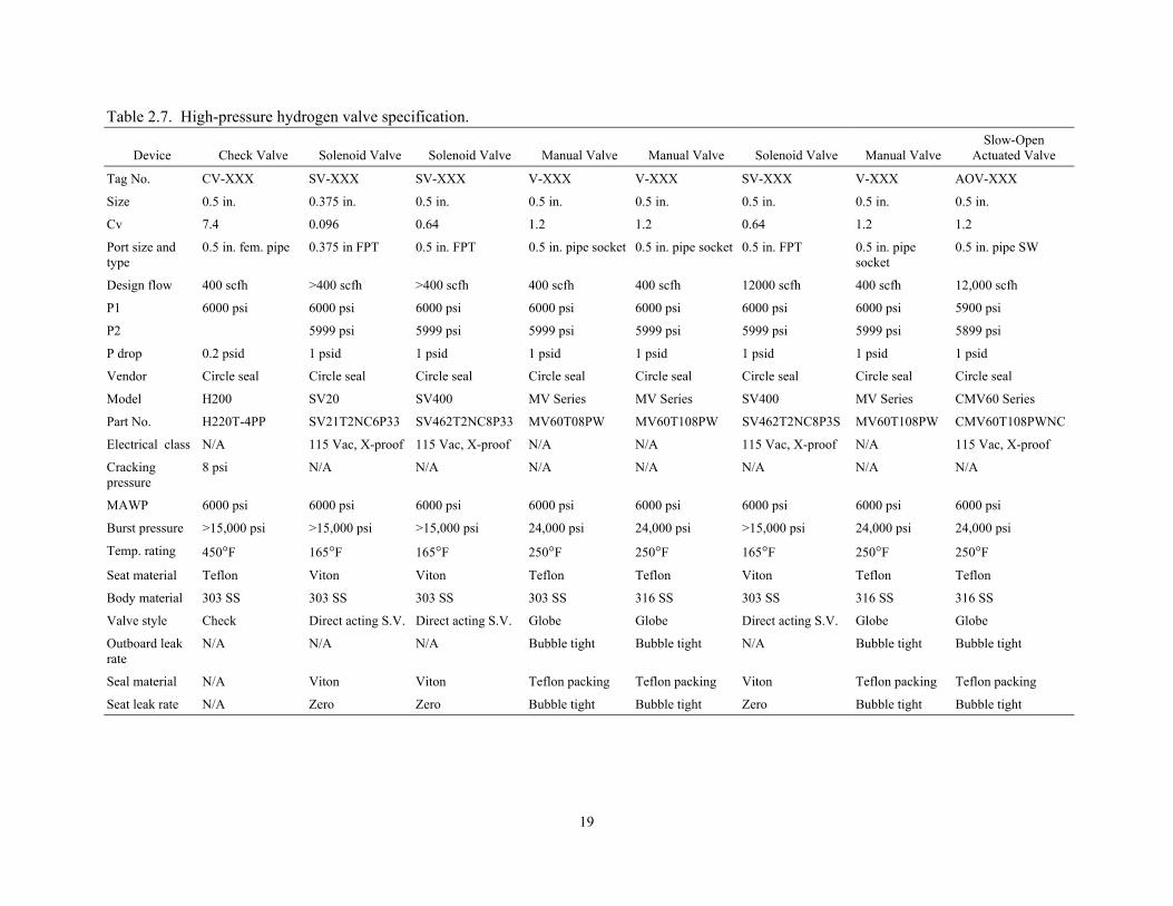
Table 2.7. High-pressure hydrogen valve specification.
Device
Check Valve
Solenoid Valve
Solenoid Valve
Manual Valve
Manual Valve
Solenoid Valve
Manual Valve Slow-Open
Actuated Valve
Tag No. CV-XXX SV-XXX SV-XXX V-XXX V-XXX SV-XXX V-XXX AOV-XXX
Size 0.5 in. 0.375 in. 0.5 in. 0.5 in. 0.5 in. 0.5 in. 0.5 in. 0.5 in.
Cv
7.4 0.096 0.64 1.2 1.2 0.64 1.2 1.2
Port size and type
0.5 in. fem. pipe 0.375 in FPT 0.5 in. FPT 0.5 in. pipe socket 0.5 in. pipe socket 0.5 in. FPT 0.5 in. pipe socket
0.5 in. pipe SW
Design flow 400 scfh >400 scfh >400 scfh 400 scfh 400 scfh 12000 scfh 400 scfh 12,000 scfh
P1 6000 psi 6000 psi 6000 psi 6000 psi 6000 psi 6000 psi 6000 psi 5900 psi
P2 5999 psi 5999 psi 5999 psi 5999 psi 5999 psi 5999 psi 5899 psi
P drop 0.2 psid 1 psid 1 psid 1 psid 1 psid 1 psid 1 psid 1 psid
Vendor Circle seal Circle seal Circle seal Circle seal Circle seal Circle seal Circle seal Circle seal
Model H200 SV20 SV400 MV Series MV Series SV400 MV Series CMV60 Series
Part No. H220T-4PP SV21T2NC6P33 SV462T2NC8P33 MV60T08PW MV60T108PW SV462T2NC8P3S MV60T108PW CMV60T108PWNC
Electrical class N/A 115 Vac, X-proof 115 Vac, X-proof N/A N/A 115 Vac, X-proof N/A 115 Vac, X-proof
Cracking pressure
8 psi N/A N/A N/A N/A N/A N/A N/A
MAWP 6000 psi 6000 psi 6000 psi 6000 psi 6000 psi 6000 psi 6000 psi 6000 psi
Burst pressure >15,000 psi >15,000 psi >15,000 psi 24,000 psi 24,000 psi >15,000 psi 24,000 psi 24,000 psi
Temp. rating 450°F 165°F 165°F 250°F 250°F 165°F 250°F 250°F
Seat material Teflon Viton Viton Teflon Teflon Viton Teflon Teflon
Body material 303 SS 303 SS 303 SS 303 SS 316 SS 303 SS 316 SS 316 SS
Valve style Check Direct acting S.V. Direct acting S.V. Globe Globe Direct acting S.V. Globe Globe
Outboard leak rate
N/A N/A N/A Bubble tight Bubble tight N/A Bubble tight Bubble tight
Seal material N/A Viton Viton Teflon packing Teflon packing Viton Teflon packing Teflon packing
Seat leak rate N/A Zero Zero Bubble tight Bubble tight Zero Bubble tight Bubble tight
19
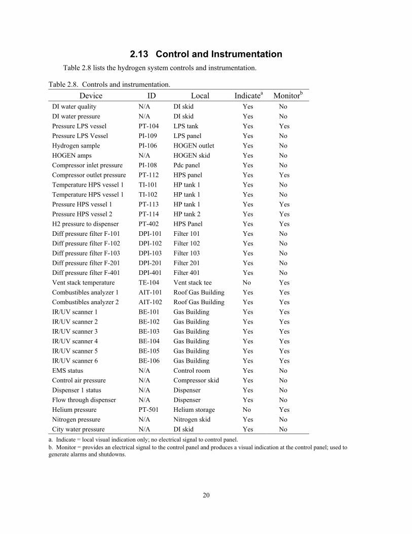
2.13 Control and Instrumentation Table 2.8 lists the hydrogen system controls and instrumentation.
Table 2.8. Controls and instrumentation. Device ID Local Indicatea Monitorb
DI water quality N/A DI skid Yes No DI water pressure N/A DI skid Yes No Pressure LPS vessel PT-104 LPS tank Yes Yes Pressure LPS Vessel PI-109 LPS panel Yes No Hydrogen sample PI-106 HOGEN outlet Yes No HOGEN amps N/A HOGEN skid Yes No Compressor inlet pressure PI-108 Pdc panel Yes No Compressor outlet pressure PT-112 HPS panel Yes Yes Temperature HPS vessel 1 TI-101 HP tank 1 Yes No Temperature HPS vessel 1 TI-102 HP tank 1 Yes No Pressure HPS vessel 1 PT-113 HP tank 1 Yes Yes Pressure HPS vessel 2 PT-114 HP tank 2 Yes Yes H2 pressure to dispenser PT-402 HPS Panel Yes Yes Diff pressure filter F-101 DPI-101 Filter 101 Yes No Diff pressure filter F-102 DPI-102 Filter 102 Yes No Diff pressure filter F-103 DPI-103 Filter 103 Yes No Diff pressure filter F-201 DPI-201 Filter 201 Yes No Diff pressure filter F-401 DPI-401 Filter 401 Yes No Vent stack temperature TE-104 Vent stack tee No Yes Combustibles analyzer 1 AIT-101 Roof Gas Building Yes Yes Combustibles analyzer 2 AIT-102 Roof Gas Building Yes Yes IR/UV scanner 1 BE-101 Gas Building Yes Yes IR/UV scanner 2 BE-102 Gas Building Yes Yes IR/UV scanner 3 BE-103 Gas Building Yes Yes IR/UV scanner 4 BE-104 Gas Building Yes Yes IR/UV scanner 5 BE-105 Gas Building Yes Yes IR/UV scanner 6 BE-106 Gas Building Yes Yes EMS status N/A Control room Yes No Control air pressure N/A Compressor skid Yes No Dispenser 1 status N/A Dispenser Yes No Flow through dispenser N/A Dispenser Yes No Helium pressure PT-501 Helium storage No Yes Nitrogen pressure N/A Nitrogen skid Yes No City water pressure N/A DI skid Yes No
a. Indicate = local visual indication only; no electrical signal to control panel. b. Monitor = provides an electrical signal to the control panel and produces a visual indication at the control panel; used to generate alarms and shutdowns.
20
2.14 Electrical The electrical energy supply is through a 48-V, 600-A, 3-phase load center located in the auxiliary
equipment area (unclassified). The interior of the building is considered to be a Class 1, Division 2, area. Wherever possible, electric equipment is placed in an unclassified area outside of the building. Purge air from the control air system is used in panels within the building. Conduits are sealed.
Grounding is with a 2/0 copper grounding grid placed in the concrete floor slab. This grid is bonded to the building steel. The grounding system also extends to the fueling island and its canopy
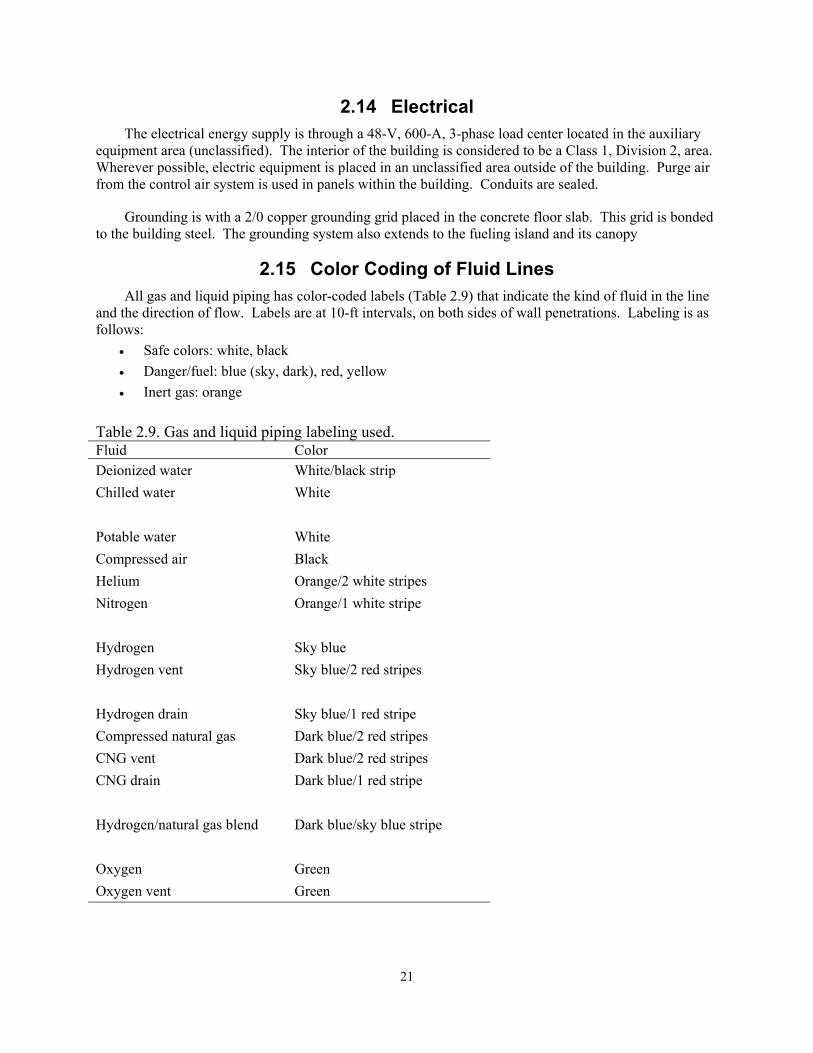
2.15 Color Coding of Fluid Lines All gas and liquid piping has color-coded labels (Table 2.9) that indicate the kind of fluid in the line
and the direction of flow. Labels are at 10-ft intervals, on both sides of wall penetrations. Labeling is as follows:
• Safe colors: white, black • Danger/fuel: blue (sky, dark), red, yellow • Inert gas: orange
Table 2.9. Gas and liquid piping labeling used. Fluid Color Deionized water White/black strip Chilled water White Potable water White Compressed air Black Helium Orange/2 white stripes Nitrogen Orange/1 white stripe Hydrogen Sky blue Hydrogen vent Sky blue/2 red stripes Hydrogen drain Sky blue/1 red stripe Compressed natural gas Dark blue/2 red stripes CNG vent Dark blue/2 red stripes CNG drain Dark blue/1 red stripe Hydrogen/natural gas blend Dark blue/sky blue stripe Oxygen Green Oxygen vent Green
21
2.16 Helium and Fire Sprinkler System The gas building is protected with a fuse-link-type fire sprinkler system.
The vent stack has a helium purge system for extinguishing any extensive fires that may develop in the vent stack. A thermocouple installed at the top (exit) of the vent stack triggers an alarm condition if exit gas temperatures reach 250ºF. Release of helium into the vent stack is manually initiated.
2.17 Flame and Flammable Gas Detection Flame detectors are Spectrex Model 20/20LB units. They scan both for IR and UV wavelength or
flame signature. Factory Mutual certifies the units. The scanners produce a series of outputs that allow an visual/audible alarm to sound at an incipient fire condition and initiate system shutdown once the detector senses a high level of IR/UV. The unit can sense flames up to 50 feet away. The gas building has five or more detectors located to completely scan the facility. Appendix F presents the coverage envelops for both the IR and UV detectors. A single unit is located at the fuel dispenser island. In this application, this UV/IR device is an industry standard. The scanners have built-in automatic testing to ensure proper operation.
The gas building has two types of gas detectors: hydrogen and natural gas. The technology and vendor for each is different. Both detectors provide an audible/visual alarm at 25% LFL for hydrogen and initiate system shutdown at 50% LFL for hydrogen.
22
3. COMPRESSED NATURAL GAS SYSTEM
3.1 Fueling Station Overview The APS Alternative Fuel Pilot Plant is a model alternative fuel refueling system supplying
compressed natural gas (CNG), hydrogen, and a blend of CNG/hydrogen. Figure A-1 of Appendix A shows a plan of the plant. The hydrogen and natural gas systems are distinctly separate; the stationary filling station blends the two fuels. This section focuses on the natural gas portion of the plant. Section 2 discusses the hydrogen portion, which is similar in various ways.
In addition to hydrogen, the plant also compresses natural gas for use as a motor fuel. CNG vehicles typically require 3,600-psi storage tanks. However, to fill vehicle onboard tanks, storage pressures must be higher. The APS system compresses natural gas to pressures up to 5,000 psi using a three-stage cascade pressure arrangement.
The objectives of constructing and operating the natural gas system are to: • Evaluate the cost and benefit ratio of operating a natural gas fueling system • Evaluate the safety of a natural gas fueling system • Provide a fuel source for APS-operated CNG and hydrogen enriched CNG (HCNG) vehicles.
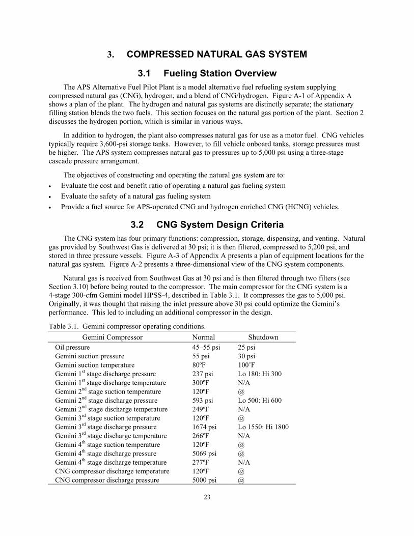
3.2 CNG System Design Criteria The CNG system has four primary functions: compression, storage, dispensing, and venting. Natural
gas provided by Southwest Gas is delivered at 30 psi; it is then filtered, compressed to 5,200 psi, and stored in three pressure vessels. Figure A-3 of Appendix A presents a plan of equipment locations for the natural gas system. Figure A-2 presents a three-dimensional view of the CNG system components.
Natural gas is received from Southwest Gas at 30 psi and is then filtered through two filters (see Section 3.10) before being routed to the compressor. The main compressor for the CNG system is a 4-stage 300-cfm Gemini model HPSS-4, described in Table 3.1. It compresses the gas to 5,000 psi. Originally, it was thought that raising the inlet pressure above 30 psi could optimize the Gemini’s performance. This led to including an additional compressor in the design.
Table 3.1. Gemini compressor operating conditions. Gemini Compressor Normal Shutdown
Oil pressure 45–55 psi 25 psi Gemini suction pressure 55 psi 30 psi Gemini suction temperature 80ºF 100˚F Gemini 1st stage discharge pressure 237 psi Lo 180: Hi 300 Gemini 1st stage discharge temperature 300ºF N/A Gemini 2nd stage suction temperature 120ºF @ Gemini 2nd stage discharge pressure 593 psi Lo 500: Hi 600 Gemini 2nd stage discharge temperature 249ºF N/A Gemini 3rd stage suction temperature 120ºF @ Gemini 3rd stage discharge pressure 1674 psi Lo 1550: Hi 1800 Gemini 3rd stage discharge temperature 266ºF N/A Gemini 4th stage suction temperature 120ºF @ Gemini 4th stage discharge pressure 5069 psi @ Gemini 4th stage discharge temperature 277ºF N/A CNG compressor discharge temperature 120ºF @ CNG compressor discharge pressure 5000 psi @
23
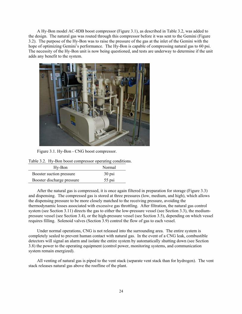
A Hy-Bon model AC-8DB boost compressor (Figure 3.1), as described in Table 3.2, was added to the design. The natural gas was routed through this compressor before it was sent to the Gemini (Figure 3.2). The purpose of the Hy-Bon was to raise the pressure of the gas at the inlet of the Gemini with the hope of optimizing Gemini’s performance. The Hy-Bon is capable of compressing natural gas to 60 psi. The necessity of the Hy-Bon unit is now being questioned, and tests are underway to determine if the unit adds any benefit to the system.
Figure 3.1. Hy-Bon - CNG boost compressor.
Table 3.2. Hy-Bon boost compressor operating conditions. Hy-Bon Normal
Booster suction pressure 30 psi Booster discharge pressure 55 psi
After the natural gas is compressed, it is once again filtered in preparation for storage (Figure 3.3)
and dispensing. The compressed gas is stored at three pressures (low, medium, and high), which allows the dispensing pressure to be more closely matched to the receiving pressure, avoiding the thermodynamic losses associated with excessive gas throttling. After filtration, the natural gas control system (see Section 3.11) directs the gas to either the low-pressure vessel (see Section 3.3), the medium-pressure vessel (see Section 3.4), or the high-pressure vessel (see Section 3.5), depending on which vessel requires filling. Solenoid valves (Section 3.9) control the flow of gas to each vessel.
Under normal operations, CNG is not released into the surrounding area. The entire system is
completely sealed to prevent human contact with natural gas. In the event of a CNG leak, combustible detectors will signal an alarm and isolate the entire system by automatically shutting down (see Section 3.8) the power to the operating equipment (control power, monitoring systems, and communication system remain energized).
All venting of natural gas is piped to the vent stack (separate vent stack than for hydrogen). The vent stack releases natural gas above the roofline of the plant.
24
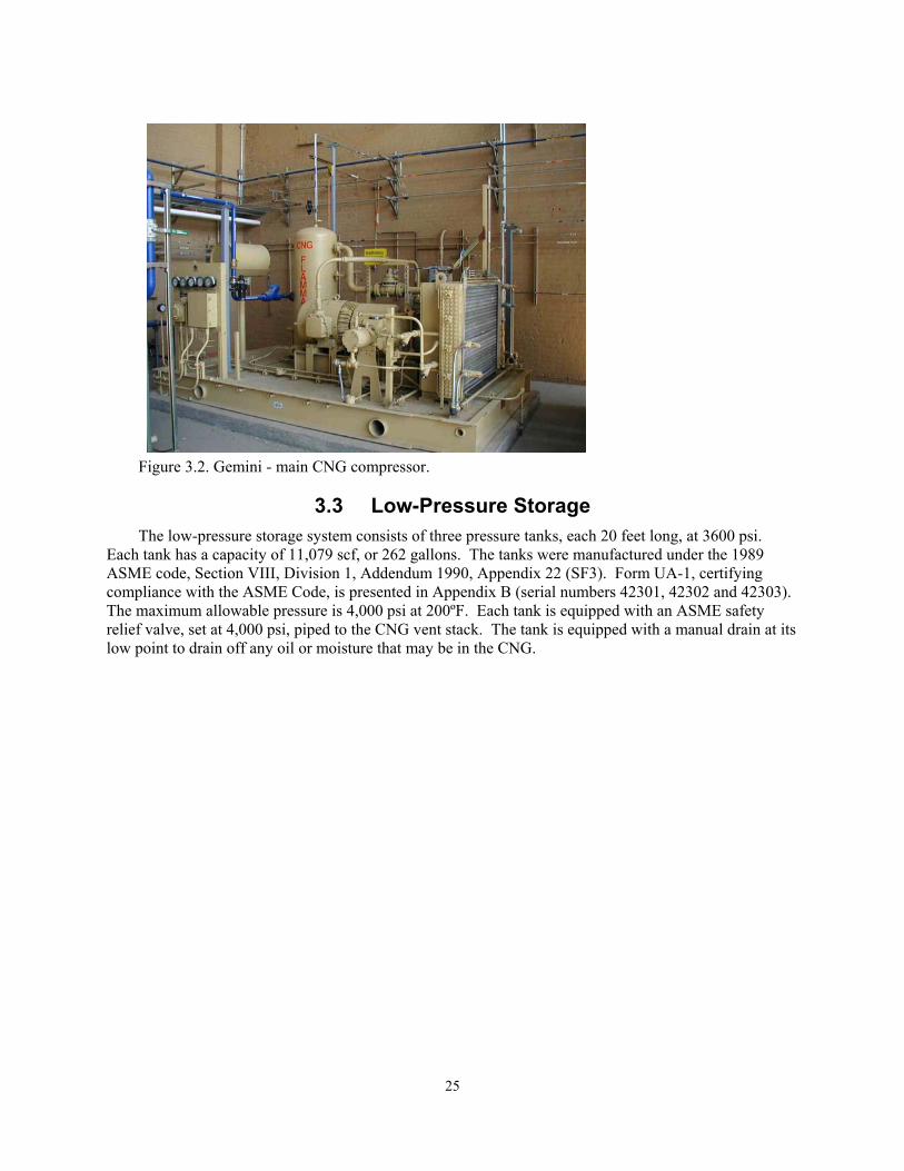
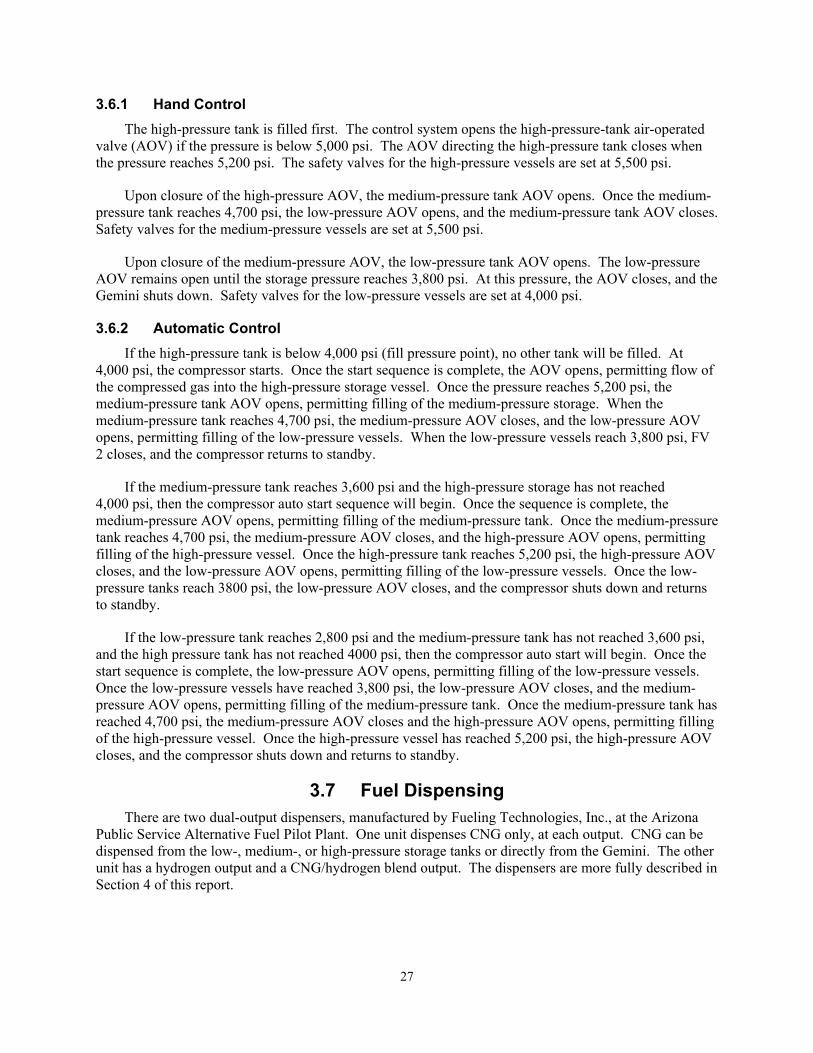
Figure 3.2. Gemini - main CNG compressor.
3.3 Low-Pressure Storage The low-pressure storage system consists of three pressure tanks, each 20 feet long, at 3600 psi.
Each tank has a capacity of 11,079 scf, or 262 gallons. The tanks were manufactured under the 1989 ASME code, Section VIII, Division 1, Addendum 1990, Appendix 22 (SF3). Form UA-1, certifying compliance with the ASME Code, is presented in Appendix B (serial numbers 42301, 42302 and 42303). The maximum allowable pressure is 4,000 psi at 200ºF. Each tank is equipped with an ASME safety relief valve, set at 4,000 psi, piped to the CNG vent stack. The tank is equipped with a manual drain at its low point to drain off any oil or moisture that may be in the CNG.
25
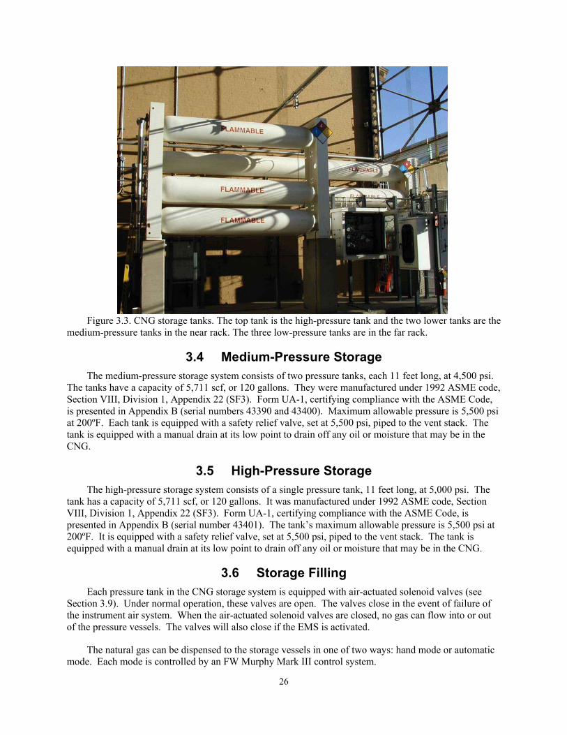
Figure 3.3. CNG storage tanks. The top tank is the high-pressure tank and the two lower tanks are the medium-pressure tanks in the near rack. The three low-pressure tanks are in the far rack.
3.4 Medium-Pressure Storage The medium-pressure storage system consists of two pressure tanks, each 11 feet long, at 4,500 psi.
The tanks have a capacity of 5,711 scf, or 120 gallons. They were manufactured under 1992 ASME code, Section VIII, Division 1, Appendix 22 (SF3). Form UA-1, certifying compliance with the ASME Code, is presented in Appendix B (serial numbers 43390 and 43400). Maximum allowable pressure is 5,500 psi at 200ºF. Each tank is equipped with a safety relief valve, set at 5,500 psi, piped to the vent stack. The tank is equipped with a manual drain at its low point to drain off any oil or moisture that may be in the CNG.
3.5 High-Pressure Storage The high-pressure storage system consists of a single pressure tank, 11 feet long, at 5,000 psi. The
tank has a capacity of 5,711 scf, or 120 gallons. It was manufactured under 1992 ASME code, Section VIII, Division 1, Appendix 22 (SF3). Form UA-1, certifying compliance with the ASME Code, is presented in Appendix B (serial number 43401). The tank’s maximum allowable pressure is 5,500 psi at 200ºF. It is equipped with a safety relief valve, set at 5,500 psi, piped to the vent stack. The tank is equipped with a manual drain at its low point to drain off any oil or moisture that may be in the CNG.
3.6 Storage Filling Each pressure tank in the CNG storage system is equipped with air-actuated solenoid valves (see
Section 3.9). Under normal operation, these valves are open. The valves close in the event of failure of the instrument air system. When the air-actuated solenoid valves are closed, no gas can flow into or out of the pressure vessels. The valves will also close if the EMS is activated.
The natural gas can be dispensed to the storage vessels in one of two ways: hand mode or automatic mode. Each mode is controlled by an FW Murphy Mark III control system.
26
3.6.1 Hand Control The high-pressure tank is filled first. The control system opens the high-pressure-tank air-operated
valve (AOV) if the pressure is below 5,000 psi. The AOV directing the high-pressure tank closes when the pressure reaches 5,200 psi. The safety valves for the high-pressure vessels are set at 5,500 psi.
Upon closure of the high-pressure AOV, the medium-pressure tank AOV opens. Once the medium-pressure tank reaches 4,700 psi, the low-pressure AOV opens, and the medium-pressure tank AOV closes. Safety valves for the medium-pressure vessels are set at 5,500 psi.
Upon closure of the medium-pressure AOV, the low-pressure tank AOV opens. The low-pressure AOV remains open until the storage pressure reaches 3,800 psi. At this pressure, the AOV closes, and the Gemini shuts down. Safety valves for the low-pressure vessels are set at 4,000 psi.
3.6.2 Automatic Control If the high-pressure tank is below 4,000 psi (fill pressure point), no other tank will be filled. At
4,000 psi, the compressor starts. Once the start sequence is complete, the AOV opens, permitting flow of the compressed gas into the high-pressure storage vessel. Once the pressure reaches 5,200 psi, the medium-pressure tank AOV opens, permitting filling of the medium-pressure storage. When the medium-pressure tank reaches 4,700 psi, the medium-pressure AOV closes, and the low-pressure AOV opens, permitting filling of the low-pressure vessels. When the low-pressure vessels reach 3,800 psi, FV 2 closes, and the compressor returns to standby.
If the medium-pressure tank reaches 3,600 psi and the high-pressure storage has not reached 4,000 psi, then the compressor auto start sequence will begin. Once the sequence is complete, the medium-pressure AOV opens, permitting filling of the medium-pressure tank. Once the medium-pressure tank reaches 4,700 psi, the medium-pressure AOV closes, and the high-pressure AOV opens, permitting filling of the high-pressure vessel. Once the high-pressure tank reaches 5,200 psi, the high-pressure AOV closes, and the low-pressure AOV opens, permitting filling of the low-pressure vessels. Once the low-pressure tanks reach 3800 psi, the low-pressure AOV closes, and the compressor shuts down and returns to standby.
If the low-pressure tank reaches 2,800 psi and the medium-pressure tank has not reached 3,600 psi, and the high pressure tank has not reached 4000 psi, then the compressor auto start will begin. Once the start sequence is complete, the low-pressure AOV opens, permitting filling of the low-pressure vessels. Once the low-pressure vessels have reached 3,800 psi, the low-pressure AOV closes, and the medium-pressure AOV opens, permitting filling of the medium-pressure tank. Once the medium-pressure tank has reached 4,700 psi, the medium-pressure AOV closes and the high-pressure AOV opens, permitting filling of the high-pressure vessel. Once the high-pressure vessel has reached 5,200 psi, the high-pressure AOV closes, and the compressor shuts down and returns to standby.
3.7 Fuel Dispensing There are two dual-output dispensers, manufactured by Fueling Technologies, Inc., at the Arizona
Public Service Alternative Fuel Pilot Plant. One unit dispenses CNG only, at each output. CNG can be dispensed from the low-, medium-, or high-pressure storage tanks or directly from the Gemini. The other unit has a hydrogen output and a CNG/hydrogen blend output. The dispensers are more fully described in Section 4 of this report.
27
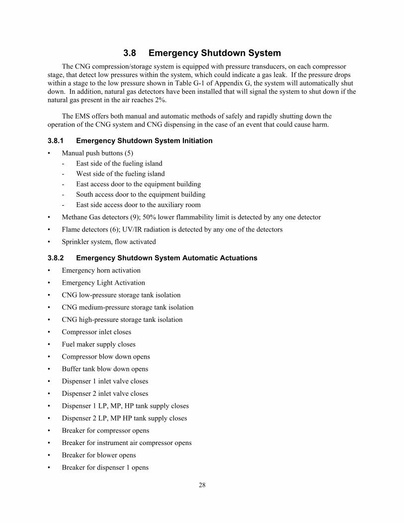
3.8 Emergency Shutdown System The CNG compression/storage system is equipped with pressure transducers, on each compressor
stage, that detect low pressures within the system, which could indicate a gas leak. If the pressure drops within a stage to the low pressure shown in Table G-1 of Appendix G, the system will automatically shut down. In addition, natural gas detectors have been installed that will signal the system to shut down if the natural gas present in the air reaches 2%.
The EMS offers both manual and automatic methods of safely and rapidly shutting down the operation of the CNG system and CNG dispensing in the case of an event that could cause harm.
3.8.1 Emergency Shutdown System Initiation • Manual push buttons (5)
- East side of the fueling island - West side of the fueling island - East access door to the equipment building - South access door to the equipment building - East side access door to the auxiliary room
• Methane Gas detectors (9); 50% lower flammability limit is detected by any one detector
• Flame detectors (6); UV/IR radiation is detected by any one of the detectors
• Sprinkler system, flow activated
3.8.2 Emergency Shutdown System Automatic Actuations • Emergency horn activation
• Emergency Light Activation
• CNG low-pressure storage tank isolation
• CNG medium-pressure storage tank isolation
• CNG high-pressure storage tank isolation
• Compressor inlet closes
• Fuel maker supply closes
• Compressor blow down opens
• Buffer tank blow down opens
• Dispenser 1 inlet valve closes
• Dispenser 2 inlet valve closes
• Dispenser 1 LP, MP, HP tank supply closes
• Dispenser 2 LP, MP HP tank supply closes
• Breaker for compressor opens
• Breaker for instrument air compressor opens
• Breaker for blower opens
• Breaker for dispenser 1 opens
28
• Breaker for dispenser 2 opens
• Breaker for equipment building lighting opens
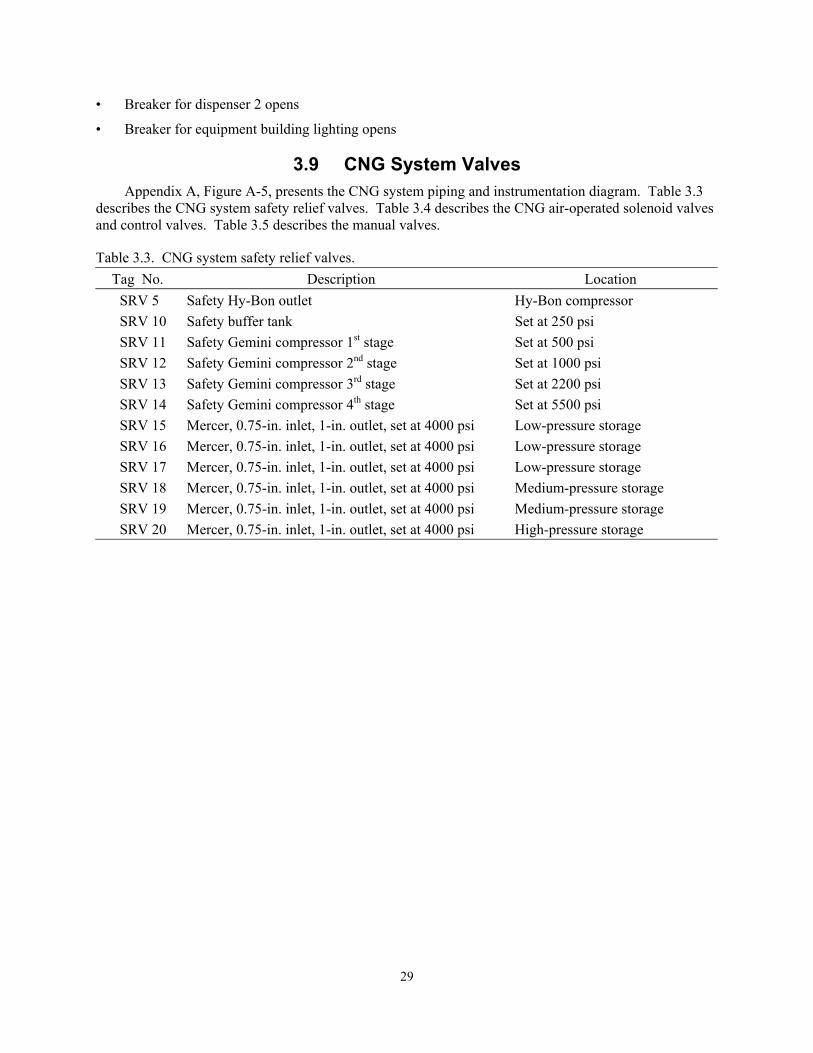
3.9 CNG System Valves Appendix A, Figure A-5, presents the CNG system piping and instrumentation diagram. Table 3.3
describes the CNG system safety relief valves. Table 3.4 describes the CNG air-operated solenoid valves and control valves. Table 3.5 describes the manual valves.
Table 3.3. CNG system safety relief valves. Tag No. Description Location
SRV 5 Safety Hy-Bon outlet Hy-Bon compressor SRV 10 Safety buffer tank Set at 250 psi SRV 11 Safety Gemini compressor 1st stage Set at 500 psi SRV 12 Safety Gemini compressor 2nd stage Set at 1000 psi SRV 13 Safety Gemini compressor 3rd stage Set at 2200 psi SRV 14 Safety Gemini compressor 4th stage Set at 5500 psi SRV 15 Mercer, 0.75-in. inlet, 1-in. outlet, set at 4000 psi Low-pressure storage SRV 16 Mercer, 0.75-in. inlet, 1-in. outlet, set at 4000 psi Low-pressure storage SRV 17 Mercer, 0.75-in. inlet, 1-in. outlet, set at 4000 psi Low-pressure storage SRV 18 Mercer, 0.75-in. inlet, 1-in. outlet, set at 4000 psi Medium-pressure storage SRV 19 Mercer, 0.75-in. inlet, 1-in. outlet, set at 4000 psi Medium-pressure storage SRV 20 Mercer, 0.75-in. inlet, 1-in. outlet, set at 4000 psi High-pressure storage
29
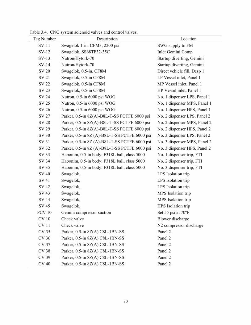
Table 3.4. CNG system solenoid valves and control valves. Tag Number Description Location
SV-11 Swagelok 1-in. CFM3, 2200 psi SWG supply to FM SV-12 Swagelok, SS68TF32-35C Inlet Gemini Comp SV-13 Nutron/Hytork-70 Startup diverting, Gemini SV-14 Nutron/Hytork-70 Startup diverting, Gemini SV 20 Swagelok, 0.5-in. CF8M Direct vehicle fill, Desp 1 SV 21 Swagelok, 0.5-in CF8M LP Vessel inlet, Panel 1 SV 22 Swagelok, 0.5-in CF8M MP Vessel inlet, Panel 1 SV 23 Swagelok, 0.5-in CF8M HP Vessel inlet, Panel 1 SV 24 Nutron, 0.5-in 6000 psi WOG No. 1 dispenser LPS, Panel 1 SV 25 Nutron, 0.5-in 6000 psi WOG No. 1 dispenser MPS, Panel 1 SV 26 Nutron, 0.5-in 6000 psi WOG No. 1 dispenser HPS, Panel 1 SV 27 Parker, 0.5-in 8Z(A)-B8L-T-SS PCTFE 6000 psi No. 2 dispenser LPS, Panel 2 SV 28 Parker, 0.5-in 8Z(A)-B8L-T-SS PCTFE 6000 psi No. 2 dispenser MPS, Panel 2 SV 29 Parker, 0.5-in 8Z(A)-B8L-T-SS PCTFE 6000 psi No. 2 dispenser HPS, Panel 2 SV 30 Parker, 0.5-in 8Z (A)-B8L-T-SS PCTFE 6000 psi No. 3 dispenser LPS, Panel 2 SV 31 Parker, 0.5-in 8Z (A)-B8L-T-SS PCTFE 6000 psi No. 3 dispenser MPS, Panel 2 SV 32 Parker, 0.5-in 8Z (A)-B8L-T-SS PCTFE 6000 psi No. 3 dispenser HPS, Panel 2 SV 33 Habonim, 0.5-in body: F318L ball, class 5000 No. 1 dispenser trip, FTI SV 34 Habonim, 0.5-in body: F318L ball, class 5000 No. 2 dispenser trip, FTI SV 35 Habonim, 0.5-in body: F318L ball, class 5000 No. 3 dispenser trip, FTI SV 40 Swagelok, LPS Isolation trip SV 41 Swagelok, LPS Isolation trip SV 42 Swagelok, LPS Isolation trip SV 43 Swagelok, MPS Isolation trip SV 44 Swagelok, MPS Isolation trip SV 45 Swagelok, HPS Isolation trip
PCV 10 Gemini compressor suction Set 55 psi at 70ºF CV 10 Check valve Blower discharge CV 11 Check valve N2 compressor discharge CV 35 Parker, 0.5-in 8Z(A) C8L-1BN-SS Panel 2 CV 36 Parker, 0.5-in 8Z(A) C8L-1BN-SS Panel 2 CV 37 Parker, 0.5-in 8Z(A) C8L-1BN-SS Panel 2 CV 38 Parker, 0.5-in 8Z(A) C8L-1BN-SS Panel 2 CV 39 Parker, 0.5-in 8Z(A) C8L-1BN-SS Panel 2 CV 40 Parker, 0.5-in 8Z(A) C8L-1BN-SS Panel 2
30
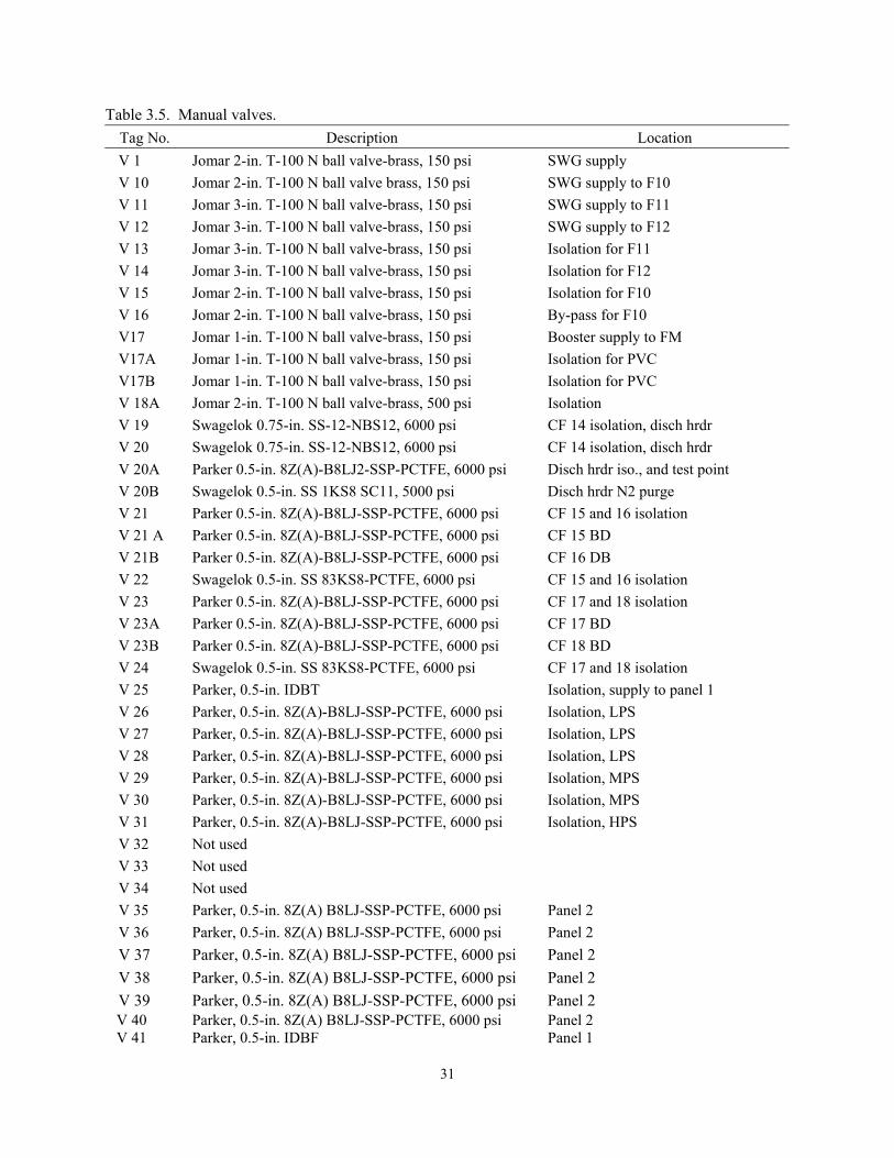
Table 3.5. Manual valves. Tag No. Description Location V 1 Jomar 2-in. T-100 N ball valve-brass, 150 psi SWG supply V 10 Jomar 2-in. T-100 N ball valve brass, 150 psi SWG supply to F10 V 11 Jomar 3-in. T-100 N ball valve-brass, 150 psi SWG supply to F11 V 12 Jomar 3-in. T-100 N ball valve-brass, 150 psi SWG supply to F12 V 13 Jomar 3-in. T-100 N ball valve-brass, 150 psi Isolation for F11 V 14 Jomar 3-in. T-100 N ball valve-brass, 150 psi Isolation for F12 V 15 Jomar 2-in. T-100 N ball valve-brass, 150 psi Isolation for F10 V 16 Jomar 2-in. T-100 N ball valve-brass, 150 psi By-pass for F10 V17 Jomar 1-in. T-100 N ball valve-brass, 150 psi Booster supply to FM V17A Jomar 1-in. T-100 N ball valve-brass, 150 psi Isolation for PVC V17B Jomar 1-in. T-100 N ball valve-brass, 150 psi Isolation for PVC V 18A Jomar 2-in. T-100 N ball valve-brass, 500 psi Isolation V 19 Swagelok 0.75-in. SS-12-NBS12, 6000 psi CF 14 isolation, disch hrdr V 20 Swagelok 0.75-in. SS-12-NBS12, 6000 psi CF 14 isolation, disch hrdr V 20A Parker 0.5-in. 8Z(A)-B8LJ2-SSP-PCTFE, 6000 psi Disch hrdr iso., and test point V 20B Swagelok 0.5-in. SS 1KS8 SC11, 5000 psi Disch hrdr N2 purge V 21 Parker 0.5-in. 8Z(A)-B8LJ-SSP-PCTFE, 6000 psi CF 15 and 16 isolation V 21 A Parker 0.5-in. 8Z(A)-B8LJ-SSP-PCTFE, 6000 psi CF 15 BD V 21B Parker 0.5-in. 8Z(A)-B8LJ-SSP-PCTFE, 6000 psi CF 16 DB V 22 Swagelok 0.5-in. SS 83KS8-PCTFE, 6000 psi CF 15 and 16 isolation V 23 Parker 0.5-in. 8Z(A)-B8LJ-SSP-PCTFE, 6000 psi CF 17 and 18 isolation V 23A Parker 0.5-in. 8Z(A)-B8LJ-SSP-PCTFE, 6000 psi CF 17 BD V 23B Parker 0.5-in. 8Z(A)-B8LJ-SSP-PCTFE, 6000 psi CF 18 BD V 24 Swagelok 0.5-in. SS 83KS8-PCTFE, 6000 psi CF 17 and 18 isolation V 25 Parker, 0.5-in. IDBT Isolation, supply to panel 1 V 26 Parker, 0.5-in. 8Z(A)-B8LJ-SSP-PCTFE, 6000 psi Isolation, LPS V 27 Parker, 0.5-in. 8Z(A)-B8LJ-SSP-PCTFE, 6000 psi Isolation, LPS V 28 Parker, 0.5-in. 8Z(A)-B8LJ-SSP-PCTFE, 6000 psi Isolation, LPS V 29 Parker, 0.5-in. 8Z(A)-B8LJ-SSP-PCTFE, 6000 psi Isolation, MPS V 30 Parker, 0.5-in. 8Z(A)-B8LJ-SSP-PCTFE, 6000 psi Isolation, MPS V 31 Parker, 0.5-in. 8Z(A)-B8LJ-SSP-PCTFE, 6000 psi Isolation, HPS V 32 Not used V 33 Not used V 34 Not used V 35 Parker, 0.5-in. 8Z(A) B8LJ-SSP-PCTFE, 6000 psi Panel 2 V 36 Parker, 0.5-in. 8Z(A) B8LJ-SSP-PCTFE, 6000 psi Panel 2 V 37 Parker, 0.5-in. 8Z(A) B8LJ-SSP-PCTFE, 6000 psi Panel 2 V 38 Parker, 0.5-in. 8Z(A) B8LJ-SSP-PCTFE, 6000 psi Panel 2 V 39 Parker, 0.5-in. 8Z(A) B8LJ-SSP-PCTFE, 6000 psi Panel 2 V 40 Parker, 0.5-in. 8Z(A) B8LJ-SSP-PCTFE, 6000 psi Panel 2 V 41 Parker, 0.5-in. IDBF Panel 1
31
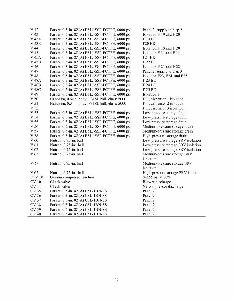
V 42 Parker, 0.5-in. 8Z(A) B8LJ-SSP-PCTFE, 6000 psi Panel 2, supply to disp 2 V 43 Parker, 0.5-in. 8Z(A) B8LJ-SSP-PCTFE, 6000 psi Isolation F 19 and F 20 V 43A Parker, 0.5-in. 8Z(A) B8LJ-SSP-PCTFE, 6000 psi F 19 BD V 43B Parker, 0.5-in. 8Z(A) B8LJ-SSP-PCTFE, 6000 psi F20 BD V 44 Parker, 0.5-in. 8Z(A) B8LJ-SSP-PCTFE, 6000 psi Isolation F 19 and F 20 V 45 Parker, 0.5-in. 8Z(A) B8LJ-SSP-PCTFE, 6000 psi Isolation F 21 and F 22 V 45A Parker, 0.5-in. 8Z(A) B8LJ-SSP-PCTFE, 6000 psi F21 BD V 45B Parker, 0.5-in. 8Z(A) B8LJ-SSP-PCTFE, 6000 psi F 22 BD V 46 Parker, 0.5-in. 8Z(A) B8LJ-SSP-PCTFE, 6000 psi Isolation F 21 and F 22 V 47 Parker, 0.5-in. 8Z(A) B8LJ-SSP-PCTFE, 6000 psi Panel 2, supply to disp 3 V 48 Parker, 0.5-in. 8Z(A) B8LJ-SSP-PCTFE, 6000 psi Isolation F23, F24, and F25 V 48A Parker, 0.5-in. 8Z(A) B8LJ-SSP-PCTFE, 6000 psi F 23 BD V 48B Parker, 0.5-in. 8Z(A) B8LJ-SSP-PCTFE, 6000 psi F 24 BD V 48C Parker, 0.5-in. 8Z(A) B8LJ-SSP-PCTFE, 6000 psi F 25 BD V 49 Parker, 0.5-in. 8Z(A) B8LJ-SSP-PCTFE, 6000 psi Isolation F V 50 Habonim, 0.5-in. body: F318L ball, class: 5000 FTI, dispenser 1 isolation V 51 Habonim, 0.5-in. body: F318L ball, class: 5000 FTI, dispenser 2 isolation V 52 FTI, dispenser 3 isolation V 53 Parker, 0.5-in. 8Z(A) B8LJ-SSP-PCTFE, 6000 psi Low-pressure storage drain V 54 Parker, 0.5-in. 8Z(A) B8LJ-SSP-PCTFE, 6000 psi Low-pressure storage drain V 55 Parker, 0.5-in. 8Z(A) B8LJ-SSP-PCTFE, 6000 psi Low-pressure storage drain V 56 Parker, 0.5-in. 8Z(A) B8LJ-SSP-PCTFE, 6000 psi Medium-pressure storage drain V 57 Parker, 0.5-in. 8Z(A) B8LJ-SSP-PCTFE, 6000 psi Medium-pressure storage drain V 58 Parker, 0.5-in. 8Z(A) B8LJ-SSP-PCTFE, 6000 psi High-pressure storage drain V 60 Nutron, 0.75-in. ball Low-pressure storage SRV isolation V 61 Nutron, 0.75-in. ball Low-pressure storage SRV isolation V 62 Nutron, 0.75-in. ball Low-pressure storage SRV isolation V 63 Nutron, 0.75-in. ball Medium-pressure storage SRV
isolation V-64 Nutron, 0.75-in. ball Medium-pressure storage SRV
isolation V 65 Nutron, 0.75-in. ball High-pressure storage SRV isolation PCV 10 Gemini compressor suction Set 55 psi at 70ºF CV 10 Check valve Blower discharge CV 11 Check valve N2 compressor discharge CV 35 Parker, 0.5-in. 8Z(A) C8L-1BN-SS Panel 2 CV 36 Parker, 0.5-in. 8Z(A) C8L-1BN-SS Panel 2 CV 37 Parker, 0.5-in. 8Z(A) C8L-1BN-SS Panel 2 CV 38 Parker, 0.5-in. 8Z(A) C8L-1BN-SS Panel 2 CV 39 Parker, 0.5-in. 8Z(A) C8L-1BN-SS Panel 2 CV 40 Parker, 0.5-in. 8Z(A) C8L-1BN-SS Panel 2
32
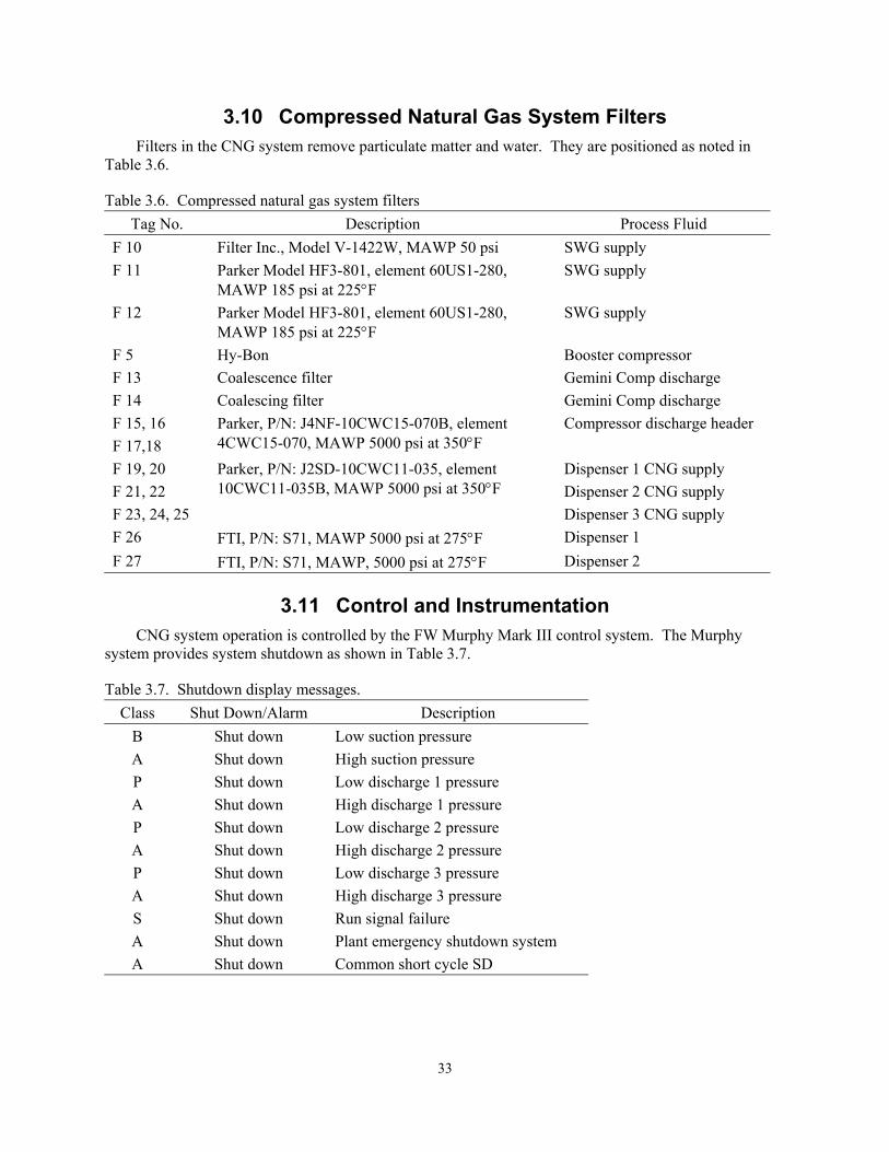
3.10 Compressed Natural Gas System Filters Filters in the CNG system remove particulate matter and water. They are positioned as noted in
Table 3.6.
Table 3.6. Compressed natural gas system filters Tag No. Description Process Fluid
F 10 Filter Inc., Model V-1422W, MAWP 50 psi SWG supply F 11 Parker Model HF3-801, element 60US1-280,
MAWP 185 psi at 225°F SWG supply
F 12 Parker Model HF3-801, element 60US1-280, MAWP 185 psi at 225°F
SWG supply
F 5 Hy-Bon Booster compressor F 13 Coalescence filter Gemini Comp discharge F 14 Coalescing filter Gemini Comp discharge F 15, 16 F 17,18
Parker, P/N: J4NF-10CWC15-070B, element 4CWC15-070, MAWP 5000 psi at 350°F
Compressor discharge header
F 19, 20 F 21, 22 F 23, 24, 25
Parker, P/N: J2SD-10CWC11-035, element 10CWC11-035B, MAWP 5000 psi at 350°F
Dispenser 1 CNG supply Dispenser 2 CNG supply Dispenser 3 CNG supply
F 26 FTI, P/N: S71, MAWP 5000 psi at 275°F Dispenser 1 F 27 FTI, P/N: S71, MAWP, 5000 psi at 275°F Dispenser 2
3.11 Control and Instrumentation
CNG system operation is controlled by the FW Murphy Mark III control system. The Murphy system provides system shutdown as shown in Table 3.7.
Table 3.7. Shutdown display messages. Class Shut Down/Alarm Description
B Shut down Low suction pressure A Shut down High suction pressure P Shut down Low discharge 1 pressure A Shut down High discharge 1 pressure P Shut down Low discharge 2 pressure A Shut down High discharge 2 pressure P Shut down Low discharge 3 pressure A Shut down High discharge 3 pressure S Shut down Run signal failure A Shut down Plant emergency shutdown system A Shut down Common short cycle SD
33
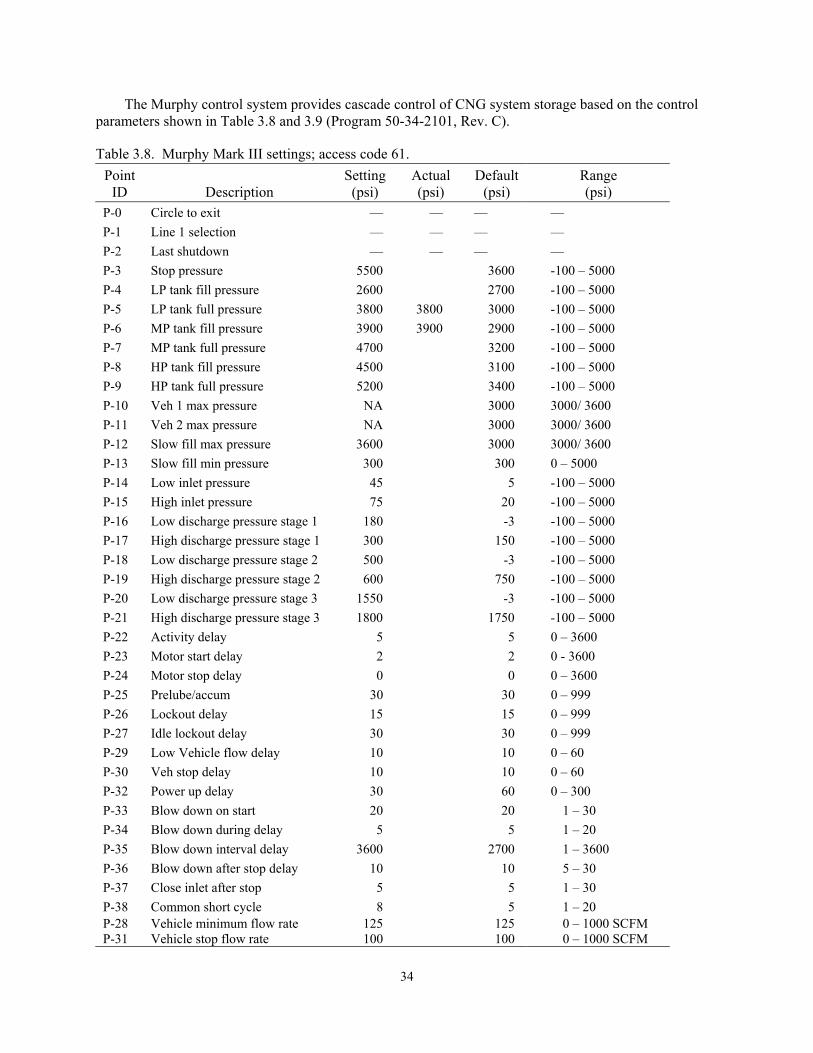
The Murphy control system provides cascade control of CNG system storage based on the control parameters shown in Table 3.8 and 3.9 (Program 50-34-2101, Rev. C).
Table 3.8. Murphy Mark III settings; access code 61. Point
ID
Description Setting
(psi) Actual (psi)
Default(psi)
Range (psi)
P-0 Circle to exit –– –– –– –– P-1 Line 1 selection –– –– –– –– P-2 Last shutdown –– –– –– –– P-3 Stop pressure 5500 3600 -100 – 5000 P-4 LP tank fill pressure 2600 2700 -100 – 5000 P-5 LP tank full pressure 3800 3800 3000 -100 – 5000 P-6 MP tank fill pressure 3900 3900 2900 -100 – 5000 P-7 MP tank full pressure 4700 3200 -100 – 5000 P-8 HP tank fill pressure 4500 3100 -100 – 5000 P-9 HP tank full pressure 5200 3400 -100 – 5000 P-10 Veh 1 max pressure NA 3000 3000/ 3600 P-11 Veh 2 max pressure NA 3000 3000/ 3600 P-12 Slow fill max pressure 3600 3000 3000/ 3600 P-13 Slow fill min pressure 300 300 0 – 5000 P-14 Low inlet pressure 45 5 -100 – 5000 P-15 High inlet pressure 75 20 -100 – 5000 P-16 Low discharge pressure stage 1 180 -3 -100 – 5000 P-17 High discharge pressure stage 1 300 150 -100 – 5000 P-18 Low discharge pressure stage 2 500 -3 -100 – 5000 P-19 High discharge pressure stage 2 600 750 -100 – 5000 P-20 Low discharge pressure stage 3 1550 -3 -100 – 5000 P-21 High discharge pressure stage 3 1800 1750 -100 – 5000 P-22 Activity delay 5 5 0 – 3600 P-23 Motor start delay 2 2 0 - 3600 P-24 Motor stop delay 0 0 0 – 3600 P-25 Prelube/accum 30 30 0 – 999 P-26 Lockout delay 15 15 0 – 999 P-27 Idle lockout delay 30 30 0 – 999 P-29 Low Vehicle flow delay 10 10 0 – 60 P-30 Veh stop delay 10 10 0 – 60 P-32 Power up delay 30 60 0 – 300 P-33 Blow down on start 20 20 1 – 30 P-34 Blow down during delay 5 5 1 – 20 P-35 Blow down interval delay 3600 2700 1 – 3600 P-36 Blow down after stop delay 10 10 5 – 30 P-37 Close inlet after stop 5 5 1 – 30 P-38 Common short cycle 8 5 1 – 20 P-28 Vehicle minimum flow rate 125 125 0 – 1000 SCFM P-31 Vehicle stop flow rate 100 100 0 – 1000 SCFM
34
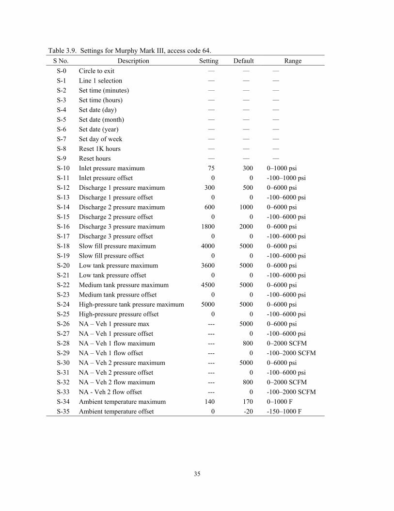
Table 3.9. Settings for Murphy Mark III, access code 64. S No. Description Setting Default Range
S-0 Circle to exit –– –– –– S-1 Line 1 selection –– –– –– S-2 Set time (minutes) –– –– –– S-3 Set time (hours) –– –– –– S-4 Set date (day) –– –– –– S-5 Set date (month) –– –– –– S-6 Set date (year) –– –– –– S-7 Set day of week –– –– –– S-8 Reset 1K hours –– –– –– S-9 Reset hours –– –– –– S-10 Inlet pressure maximum 75 300 0–1000 psi S-11 Inlet pressure offset 0 0 -100–1000 psi S-12 Discharge 1 pressure maximum 300 500 0–6000 psi S-13 Discharge 1 pressure offset 0 0 -100–6000 psi S-14 Discharge 2 pressure maximum 600 1000 0–6000 psi S-15 Discharge 2 pressure offset 0 0 -100–6000 psi S-16 Discharge 3 pressure maximum 1800 2000 0–6000 psi S-17 Discharge 3 pressure offset 0 0 -100–6000 psi S-18 Slow fill pressure maximum 4000 5000 0–6000 psi S-19 Slow fill pressure offset 0 0 -100–6000 psi S-20 Low tank pressure maximum 3600 5000 0–6000 psi S-21 Low tank pressure offset 0 0 -100–6000 psi S-22 Medium tank pressure maximum 4500 5000 0–6000 psi S-23 Medium tank pressure offset 0 0 -100–6000 psi S-24 High-pressure tank pressure maximum 5000 5000 0–6000 psi S-25 High-pressure pressure offset 0 0 -100–6000 psi S-26 NA – Veh 1 pressure max --- 5000 0–6000 psi S-27 NA – Veh 1 pressure offset --- 0 -100–6000 psi S-28 NA – Veh 1 flow maximum --- 800 0–2000 SCFM S-29 NA – Veh 1 flow offset --- 0 -100–2000 SCFM S-30 NA – Veh 2 pressure maximum --- 5000 0–6000 psi S-31 NA – Veh 2 pressure offset --- 0 -100–6000 psi S-32 NA – Veh 2 flow maximum --- 800 0–2000 SCFM S-33 NA - Veh 2 flow offset --- 0 -100–2000 SCFM S-34 Ambient temperature maximum 140 170 0–1000 F S-35 Ambient temperature offset 0 -20 -150–1000 F
35
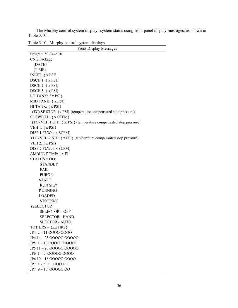
The Murphy control system displays system status using front panel display messages, as shown in Table 3.10.
Table 3.10. Murphy control system displays. Front Display Messages
Program 50-34-2101 CNG Package DATE TIME INLET: x PSI DSCH 1: x PSI DSCH 2: x PSI DSCH 3: x PSI LO TANK: x PSI MID TANK: x PSI HI TANK: x PSI (TC) SF STOP: x PSI (temperature compensated stop pressure) SLOWFILL: x SCFM (TC) VEH 1 STP: X PSI (temperature compensated stop pressure) VEH 1: x PSI DISP 1 FLW: x SCFM (TC) VEH 2 STP: x PSI (temperature compensated stop pressure) VEH 2: x PSI) DISP 2 FLW: x SCFM AMBIENT TMP: x F STATUS = OFF STANDBY FAIL PURGE START RUN SIG? RUNNING LOADED STOPPING (SELECTOR) SELECTOR – OFF SELECTOR - HAND SLECTOR - AUTO TOT HRS = x.x HRS JP4 2 – 11 OOOO OOOO JP4 14 – 23 OOOOO OOOOO JP5 1 – 10 OOOOO OOOOO JP5 11 – 20 OOOOO OOOOO JP6 1 – 9 OOOOO OOOO JP6 10 – 18 OOOOO OOOO JP7 1 - 7 OOOOO OO JP7 9 – 15 OOOOO OO
36
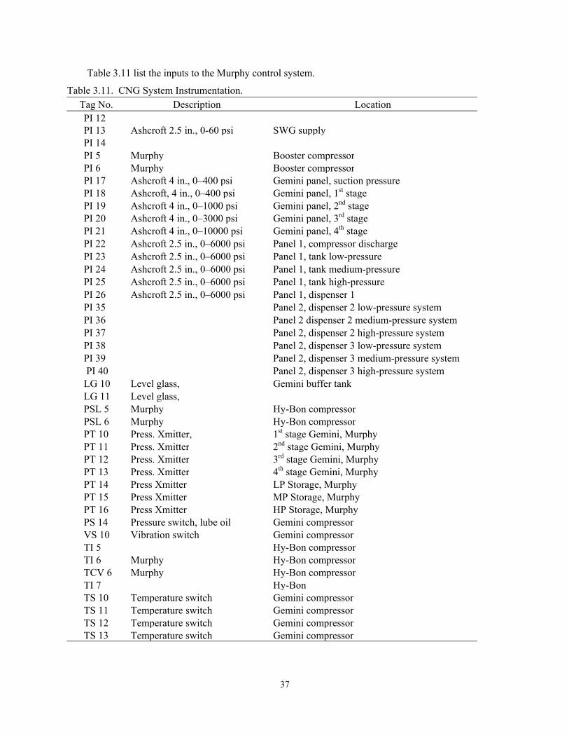
Table 3.11 list the inputs to the Murphy control system.
Table 3.11. CNG System Instrumentation. Tag No. Description Location PI 12 PI 13 Ashcroft 2.5 in., 0-60 psi SWG supplyPI 14 PI 5 Murphy Booster compressorPI 6 Murphy Booster compressorPI 17 Ashcroft 4 in., 0–400 psi Gemini panel, suction pressure PI 18 Ashcroft, 4 in., 0–400 psi Gemini panel, 1st stagePI 19 Ashcroft 4 in., 0–1000 psi Gemini panel, 2nd stagePI 20 Ashcroft 4 in., 0–3000 psi Gemini panel, 3rd stagePI 21 Ashcroft 4 in., 0–10000 psi Gemini panel, 4th stage PI 22 Ashcroft 2.5 in., 0–6000 psi Panel 1, compressor discharge PI 23 Ashcroft 2.5 in., 0–6000 psi Panel 1, tank low-pressure PI 24 Ashcroft 2.5 in., 0–6000 psi Panel 1, tank medium-pressure PI 25 Ashcroft 2.5 in., 0–6000 psi Panel 1, tank high-pressure PI 26 Ashcroft 2.5 in., 0–6000 psi Panel 1, dispenser 1 PI 35 Panel 2, dispenser 2 low-pressure system PI 36 Panel 2 dispenser 2 medium-pressure system PI 37 Panel 2, dispenser 2 high-pressure system PI 38 Panel 2, dispenser 3 low-pressure system PI 39 Panel 2, dispenser 3 medium-pressure system PI 40 Panel 2, dispenser 3 high-pressure system LG 10 Level glass, Gemini buffer tank LG 11 Level glass, PSL 5 Murphy Hy-Bon compressorPSL 6 Murphy Hy-Bon compressorPT 10 Press. Xmitter, 1st stage Gemini, MurphyPT 11 Press. Xmitter 2nd stage Gemini, MurphyPT 12 Press. Xmitter 3rd stage Gemini, MurphyPT 13 Press. Xmitter 4th stage Gemini, MurphyPT 14 Press Xmitter LP Storage, MurphyPT 15 Press Xmitter MP Storage, MurphyPT 16 Press Xmitter HP Storage, MurphyPS 14 Pressure switch, lube oil Gemini compressorVS 10 Vibration switch Gemini compressorTI 5 Hy-Bon compressorTI 6 Murphy Hy-Bon compressorTCV 6 Murphy Hy-Bon compressorTI 7 Hy-BonTS 10 Temperature switch Gemini compressorTS 11 Temperature switch Gemini compressorTS 12 Temperature switch Gemini compressorTS 13 Temperature switch Gemini compressor
37
4. FUEL DISPENSING
The APS Alternative Fuel Pilot Plant is located within the boundaries of the APS service yard, located at 501 South 2nd Avenue, in Phoenix, Arizona. Fuel is dispensed at the (APS) 501 facility in support of its operating fleet of light- and heavy-duty trucks performing electrical system maintenance and meter reading for APS. The liquid and electric fueling infrastructure was already in place at the 501 facility (described in Sections 4.1.1 and 4.1.2) before the gaseous refueling infrastructure was constructed (described in Section 4.1.3).
4.1 Refueling Equipment at the 501 Facility 4.1.1 Existing Liquid Refueling Systems
The previously existing petroleum vehicle refueling system is aboveground and dispenses both unleaded gasoline and diesel fuels. It has existed for several years and replaced belowground tanks. It has one 2,000-gallon aboveground gasoline storage tank and one 2,000-gallon aboveground diesel tank. The petroleum refueling equipment is centrally located in the southern parking area, which also serves as an assembly area at the start and at the end of the day shift. No vapor recovery system has been installed on the tank or on dispenser hoses. Tank vent stacks are protected to prevent blockage by insects or birds and from entry of foreign objects. The tanks are free to vent to the atmosphere. A spill prevention dike is installed, but no bollards exist to protect the tanks from vehicle intrusion (hazard exists because maneuvering space in the area for large vehicle operation is limited). The physical and open-air distance between the tanks is 66 inches. No fire containment or barrier wall exists between the tanks. No fire detection equipment or alarms exist on the tank and fuel dispensing systems. And no fire fighting or fogging systems are installed. Flammable material is stored within the fuel dispenser spill containment area (two garbage cans with flammable trash). Hand-held fire extinguishers are mounted on the south outboard canopy post supports, about 21 inches from the longitudinal axis of the tanks. Electrical junction boxes in the fuel dispensing control are not Class 1, explosion proof. There have been no reported safety incidents, fires, or explosions since installation of this system.
4.1.2 Existing Electric Refueling Systems There is an electric vehicle recharging area (area 401) approximately 400 feet north of the 501
fueling area and north of the meter reader parking area. This area is equipped with the following systems:
• One 150-kW Minit charger (24 to 400 V, 400 amp max., all battery chemistries, non-2293 vehicles)
• One 150-kW Minit charger compatible with 2293 DaimlerChrysler vehicles (model year 1999–2003, 400 amp maximum, all battery chemistries, including NMH)
• One 120-kW Minit charger (24 to 455 V, 500 amp maximum, all battery chemistries, all vehicles, including 2293 DaimlerChrysler),
• One 33-kW SuperCharge (all vehicles except 2293 DaimlerChrysler)
• Four GM Level II inductive chargers
• One SCI Level II conductive charger
• One Avcon Level II conductive charger.
There are hand-held fire extinguishers in the charging area. There are no emissions from this refueling system, and there is no hazardous material in storage. There have been no safety incidents or fires since installation of these systems.
38
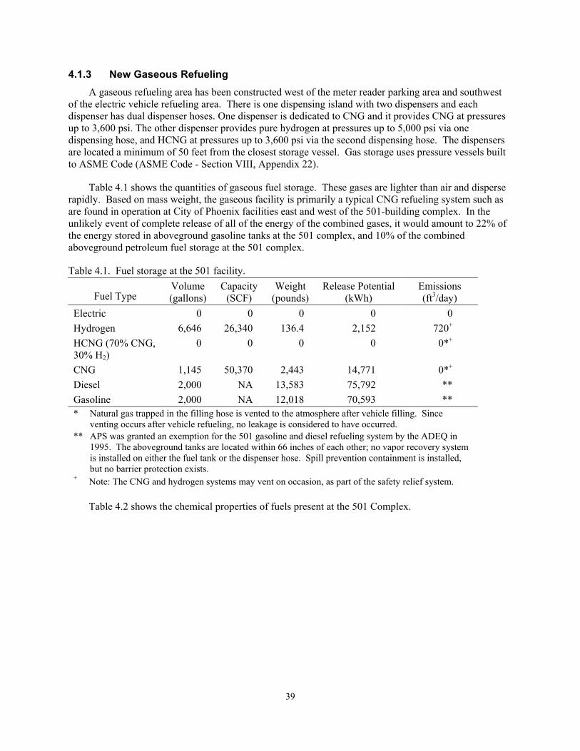
4.1.3 New Gaseous Refueling A gaseous refueling area has been constructed west of the meter reader parking area and southwest
of the electric vehicle refueling area. There is one dispensing island with two dispensers and each dispenser has dual dispenser hoses. One dispenser is dedicated to CNG and it provides CNG at pressures up to 3,600 psi. The other dispenser provides pure hydrogen at pressures up to 5,000 psi via one dispensing hose, and HCNG at pressures up to 3,600 psi via the second dispensing hose. The dispensers are located a minimum of 50 feet from the closest storage vessel. Gas storage uses pressure vessels built to ASME Code (ASME Code - Section VIII, Appendix 22).
Table 4.1 shows the quantities of gaseous fuel storage. These gases are lighter than air and disperse rapidly. Based on mass weight, the gaseous facility is primarily a typical CNG refueling system such as are found in operation at City of Phoenix facilities east and west of the 501-building complex. In the unlikely event of complete release of all of the energy of the combined gases, it would amount to 22% of the energy stored in aboveground gasoline tanks at the 501 complex, and 10% of the combined aboveground petroleum fuel storage at the 501 complex.
Table 4.1. Fuel storage at the 501 facility.
Fuel Type Volume (gallons)
Capacity(SCF)
Weight (pounds)
Release Potential (kWh)
Emissions (ft3/day)
Electric 0 0 0 0 0 Hydrogen 6,646 26,340 136.4 2,152 720+ HCNG (70% CNG, 30% H2)
0 0 0 0 0*+
CNG 1,145 50,370 2,443 14,771 0*+ Diesel 2,000 NA 13,583 75,792 ** Gasoline 2,000 NA 12,018 70,593 ** * Natural gas trapped in the filling hose is vented to the atmosphere after vehicle filling. Since
venting occurs after vehicle refueling, no leakage is considered to have occurred. ** APS was granted an exemption for the 501 gasoline and diesel refueling system by the ADEQ in
1995. The aboveground tanks are located within 66 inches of each other; no vapor recovery system is installed on either the fuel tank or the dispenser hose. Spill prevention containment is installed, but no barrier protection exists.
+ Note: The CNG and hydrogen systems may vent on occasion, as part of the safety relief system.
Table 4.2 shows the chemical properties of fuels present at the 501 Complex.
39

Table 4.2. Fuel properties.
Property Hydrogen Methane Propane Gasoline Diesel Methanol Acetylene
Density (20ºC, 1 atm) lb/ft3 Kg/l
0.00518 0.000083
0.0485 0.00078
0.1168 0.00187
44.95 0.72
50.8
49.4
0.0704
Specific gravity air = 1.0 water = 1.0
0.0696
0.554
1.562
3.90 0.733
0.814
0.791
0.92
Diffusion coefficient (m/sec) ft/sec
0.0061 0.0200
0.0016 0.0052
0.0012 0.0039
0.008 0.026
Heat energy (weight basis) Wh/kg BTU/lb
39,472 61,095
15,425 23,875
13,891 21,500
12,922 20,000
12,276 19,000
6,332 9,800
13,892 21,502
Heat Energy (volume basis) Wh/l BTU/Ft3
3 325
10 1,012
27 2,524
8,890 860
752
1,477 Flammability limits (% volume in air)
4 to 75
5 to 16
2 to 12
1.4 to 7.6
6.7 to 36
2.5 to 81
Optimum air/fuel (% volume in air)
2.38
9.53
23.8
1.76
11.9
Ignition temperature ºF ºC
1,062 572
1,170 632
919 493
536 280
490-560 254-293
725 385
581 305
Ignition energy, air watt BTU
6 × 10⁻⁹
2 × 10⁻⁸
8 × 10⁻⁸ 3 × 10⁻⁷
7 × 10⁻⁸
3 × 10⁻⁷
7 × 10⁻⁸ 2 × 10⁻⁷
Flame temperature ºF ºC
3,713 2,045
3,416 1,880
3,573 1,967
4,190 2,310
3,460 1,904
4,207 2,319
Flame speed ft/sec m/sec
9.3
2.83
1.5
0.46
1.5
0.46
1.31 0.40
8.8
2.68 Fuel From Water, eighth edition, Michael A. Peavey, Merit Inc., p. 225. Petroleum Engineers Handbook, 5th edition, McGraw Hill
4.2 Fuel Dispensing System Description
Both hydrogen and CNG vehicular dispensing is performed in the same manner. Fueling Technologies Inc. manufactured the fuel dispensers for each fuel. The hydrogen dispenser is a dual station. One hose dispenses hydrogen into a vehicle with a pressure rating of up to 5,000 psi. The other hose dispenses a hydrogen-enriched CNG at a vehicle pressure rating of up to 3,600 psi.
Each of the dispensers has individual displays. The displays indicate the amount of fuel dispensed in GGE (gasoline gallon equivalent), the total cost for the fuel dispensed, and the unit cost by gallon. The output hose assemblies and the nozzle that connects to the vehicle are coordinated with the type of fuel that is to be dispensed. Thereby, the nozzle from the hydrogen dispenser can be connected only to a vehicle designed for hydrogen, and the nozzle from the CNG dispenser can be connected only to a vehicle designed for CNG.
40
4.2.1 Hydrogen Dispenser Operation The hydrogen dispensers have a maximum inlet pressure rating of 5,000 psi. Special nozzle and
hose assemblies designed and manufactured by WEH (Germany) provide a mechanical guarantee that CNG vehicles cannot obtain fuel from the hydrogen or HCNG refueling system. In addition to the mechanical incompatibility of fueling nozzles, the system is authorized by an interlocking commercial access system provided by Pickens Fuel. All hose assemblies are also equipped with a breakaway connection at the output of the dispenser housing.
The fuel dispensing system also provides cascade control of the high-pressure storage vessels during refueling. Independent of the fueling control system and emergency shutdown system, excess flow valves in the hydrogen piping to the dispenser protect against pipe and hose failures. If hydrogen flow exceeds a predetermined amount, the flow control will shut off the flow of hydrogen to the dispenser.
4.2.2 CNG Dispenser Operation The natural gas dispensers have a maximum inlet pressure rating of 5,000 psi, a service pressure
rating of 3,600 psi, and a flow rate of 0.5 lb/min. Each hose is equipped with a Shurex, NGV1, Type 1, Class A nozzle. These nozzles are unique and are commonly used for compressed natural gas vehicles. The output assembly combines two hoses in one. One hose is used for the process gas. The other hose is used for venting. The process gas hose is Furon/Synflex, 35NG-06, 3/8-in. ID, with a maximum pressure rating of 5,000 psi. The vent hose is Furon/Synflex, 35NG-03, 3/16-in. ID, with a maximum pressure rating of 5,000 psi, and is considered electrically conductive for CNG. These hoses meet the standard, AGA 1-93. All hose assemblies are also equipped with a breakaway connection at the output of the dispenser housing.
41
5. LESSIONS LEARNED
During the siting process, detailed design, and construction of the APS Alternative Fuel Pilot Plant, numerous lessons were learned that will improve the performance and reduce the cost of the next generation of fueling stations. These lessons learned are presented in the following sections.
5.1 Codes And Standards Existing codes for storage of compressed hydrogen gas present significant obstacles to developing
commercial hydrogen fueling stations (Appendix H). The definition of indoor facilities and setback distances are two examples of requirements that will make the size of fueling stations using existing design concepts unacceptable for commercial application. These standards have been developed based on years of experience and a significant body of expertise. They represent best-practice requirements to protect the public from the hazards of stored gas. Future designs will require novel concepts to accommodate these standards within the constraints imposed by a commercial fueling station site. Both new designs and analyses will be required to accomplish the requisite objectives.
5.2 Facility Layout The current state of the art for facility arrangement is represented by industrial gas facilities. These
facilities typically use a flat arrangement, where equipment and piping are located at near-ground level. For commercial hydrogen fueling stations, significant reductions in hazards can be achieved by using a three-dimensional layout, including the following design features:
• Elevated or vertical tanks, with penetrations and piping at a level to prevent flame jet impingement on personnel in the event of a high-pressure leak.
• Physical separation of piping associated with different storage vessels to prevent cascading failures resulting from flame jet impingement.
5.3 Piping The current state of the art for piping design of commercial compressed gas facilities is represented
by compressed natural gas fueling stations. The standards used by the natural gas industry were found to be inadequate in the following areas:
• Vents and drains are typically open to the atmosphere in a natural gas design. In a hydrogen fueling station, the vents and drains must be piped to a blowdown tank and vent stack to prevent any gas release in occupied areas of the facility.
• Compression fittings are used extensively in the natural gas industry. These fittings are not adequate to ensure the long-term integrity of high-pressure hydrogen piping. All high-pressure hydrogen piping must be welded and inspected as appropriate to ensure weld integrity.
• Care must be taken to ensure that all pressure boundary components are certified by their manufacturer for hydrogen service at the pressures and temperatures required. Many commonly used fittings and valves advertised for hydrogen use are not certified by their manufacturers for such duty.
5.4 Electrical Grounding
Elimination of static or lighting-induced sparks in a hydrogen fueling station is imperative. Careful attention must be given to equipment grounding and earth grounding of the facility.
42
5.5 Construction Construction of a hydrogen fueling station requires the accommodation of several unique processes:
• A significant amount of high-pressure welding is required. Arrangements for qualified welders and machine welding equipment must be made to facilitate construction.
• Piping system cleanliness must be maintained during construction by the use of precleaned tubing and vessels and exercise of due care during construction to maintain cleanliness.
• Hydrostatic pressure testing of completed piping must be accomplished while maintaining cleanliness requirements.
5.6 Fuel Dispensing Existing fuel dispensers for hydrogen fuel and blends of hydrogen fuel and CNG are not adequate to
support commercial hydrogen fueling. Cost reliability and safety must be significantly improved to allow commercial fueling.
43
44
6. LIST OF APPENDICES
APPENDIX A – SYSTEM DRAWINGS
APPENDIX B - FORMS AND LISTS
APPENDIX C – GASEOUS HYDROGEN PIPING SPECIFICATION
APPENDIX D - TRAINING PROGRAMS
APPENDIX E – HYDROGEN SYSTEMS OPERATIONS
APPENDIX F – FLAME SCANNERS AND SENSORS
APPENDIX G – COMPRESSED NATURAL GAS SYSTEM OPERATIONS
APPENDIX H – CODES AND STANDARD