Embed Size (px)
Citation preview


A/23 MFFI - A/27 MFFIG.C.N. 47-116-10 / 47-116-12Installation InstructionsType C BoilersLEAVE THESE INSTRUCTIONSADJACENT TO THE GAS METER
Country of destination: GB
2 B023
TABLE OF CONTENTS 1. GENERAL INFORMATION
1.1 General Instructions1.2 Technical Information1.3 Overall View
2. INSTALLATION
2.1 Reference Standards2.2 Siting the Appliance2.3 Overall Dimensions2.4 Clearances2.5 Mounting the Appliance2.6 Electrical Connection2.7 Gas Connection2.8 Water Connections2.9 Flue Connection2.10 Room Thermostat Connection2.11 Electrical/System Diagrams2.12 Water Circuit Diagrams
3. COMMISSIONING
3.1 Initial Preparation3.2 Removing the Front Panel3.3 Control Panel3.4 Initial Start-up3.5 Operational Adjustments3.6 Combustion Analysis3.7 Fume Discharge Monitoring3.8 Boiler Safety Systems3.9 Draining the System
4. GAS ADJUSTMENTS
Gas Adjustment Table4.1 Changing the Type of Gas
5. MAINTENANCE
6. MISCELLANEOUS
6.1 Wiring Diagram for Two Heating Zones6.2 Wiring Diagram for Connection to Ariston Unvented Cylinderl

3B023
This manual is an integral and essential part of the product. It should be keptwith the appliance so that it can be consulted by the user and our authorisedpersonnel.
Please carefully read the instructions and notices about the unit contained inthis manual, as they provide important information regarding the safeinstallation, use and maintenance of the product.
For operating instructions please consult the separate User’s Manual.
Read the instructions and recommendations in these Installation Instructionscarefully to ensure proper installation, use and maintenance of the appliance.
Keep this manual in a safe place. You may need it for your own reference whileour Servicing Centre technicians or your installer may need to consult it in thefuture.
This is a combined appliance for the production of central heating (C.H.) anddomestic hot water (D.H.W.).
This appliance must be used only for the purpose for which it is designed.The manufacturer declines all liability for damage caused by improper ornegligent use.
No asbestos or other hazardous materials have been used in the fabrication ofthis product.
Before connecting the appliance, check that the information shown on the dataplate and the table on pages 4-5 comply with the electric, water and gas mainsof the property.You will find the data plate on the reverse of the control panel.The gas with which this appliance operates is also shown on the label at thebottom of the boiler.
Do not install this appliance in a damp environment or close to equipmentwhich spray water or other liquids.Do not place objects on the appliance.Do not allow children or inexperienced persons to use the appliance withoutsupervision.
If you smell gas in the room, do not turn on light switches, use the telephone orany other object which might cause sparks.Open doors and windows immediately to ventilate the room.Shut the gas mains tap (on the gas meter) or the valve of the gas cylinder andcall your Gas Supplier immediately.If you are going away for a long period of time, remember to shut the mains gastap or the gas cylinder valve.
Always disconnect the appliance either by unplugging it from the mains orturning off the mains switch before cleaning the appliance or carrying outmaintenance.
In the case of faults or failure , switch off the appliance and turn off the gastap. Do not tamper with the appliance.For repairs, call your local Authorised Servicing Centre and request the use oforiginal spare parts. For in-guarantee repairs contact MTS (GB) Limited.
Check the following at least once a year:1 - Check the seal of water connections, replacing the gaskets if necessary.2 - Check the seal of the gas connections, replacing the gaskets if necessary.3 - Check the general condition of the appliance and of the combustion
1. GENERALINFORMATION
User’sManual
A/23 MFFIA/27 MFFI
1.1 General Instructions

CE CertificationHeat Input max/min kW 25.6/11.0Heat Output max/min kW 23.1/9.2Efficiency of Nominal Heat Input % 90.2Efficiency at 30% of Nominal Heat Input % 87.8Heat Loss to the Casing (³T=50°C) % 1.2Flue Heat Loss with Burner Operating % 8.6Flue Heat Loss with Burner Off % 0.4Maximum Discharge of Fumes (G20-G25) Kg/h 59Residual Discharge Head mbar 1.15Consumption at Nominal Capacity (G20-G25) m3/h 2.72/3.32Gas Consumption after 10 Minutes* m3 0.32/0.39(15°C, 1013 mbar) (G30-G31) Kg/h 2.02/2.00Temp. of exhaust fumes at nominalcapacity (G20-G25) °C 137CO2 Content % 5.8
O2 Content % 9.2
CO Content ppm 32Minimum Ambient Temperature °C +5Head Loss on Water Side (max) (³T=20°C) mbar 200Residual Head of System bar 0.25Heating Temperature max/min °C 82/42Domestic Hot Water Temperature max/min °C 56/36D.H.W. Flow Rate ³T=35°C l/min 9.5D.H.W. Flow Rate ³T=35°C gal/min 2.1D.H.W. Minimum Flow Rate l/min 2.6Pressure of Domestic Hot Water max/min bar 6/0.2Expansion Vessel Capacity l 7Expansion Vessel Pre-load Pressure bar 1Maximum Water Content in System l 145Maximum Heating Pressure bar 3Nominal Pressure Natural Gas (G20-G25) mbar 20-25
LPG (G30-G31) mbar 30-37Electrical Supply V/Hz 230 / 50Power Consumption W 150Protection Grade of Electrical System IP 44Internal Fuse Rating FAST 2 ATWeight Kg. 47
G.C. Number 47-116-10
4 B023
1.2 Technical Information
chamber visually.4 - Visual check of the combustion: clean burners if necessary.5 - With reference to point 3, dismantle and clean the combustion chamber if
necessary.6 - With reference to point 4, dismantle and clean the injectors if necessary.7 - Visual check of the primary heat exchanger:
- check for overheating of the exchangers fins;- clean the exhaust side of the exchanger and fan if necessary.
8 - Regulate the gas pressure, ignition pressure, partial flame, maximum flame.
9 - Check proper operation of the heating safety system:- maximum safety temperature;- maximum safety pressure.
10 - Check the proper operation of the gas safety system:- gas or flame safety device;- gas valve safety device.
11 - Check that the electrical connections have been made in compliance withthe instructions shown in the installation instructions.
12 - Check the efficiency of the hot water supply (flow and temperature).13 - Check general operation of the appliance.14 - Check the exhaust system for the combustion products.
29.8/12.027.3/10.1
91.688.31.37.10.4621.4
3.16/3.860.37/0.452.35/2.32
1286.6
8.0
34+52000.25
82/4256/3611.22.52.6
6/0.271
1453
20-2530-37
230 / 5019044
FAST 2 AT47
47-116-12
A/23 MFFI A/27 MFFI
*Calculated at 70% maximum output
5B023
A/23 MFFI - A/27 MFFI
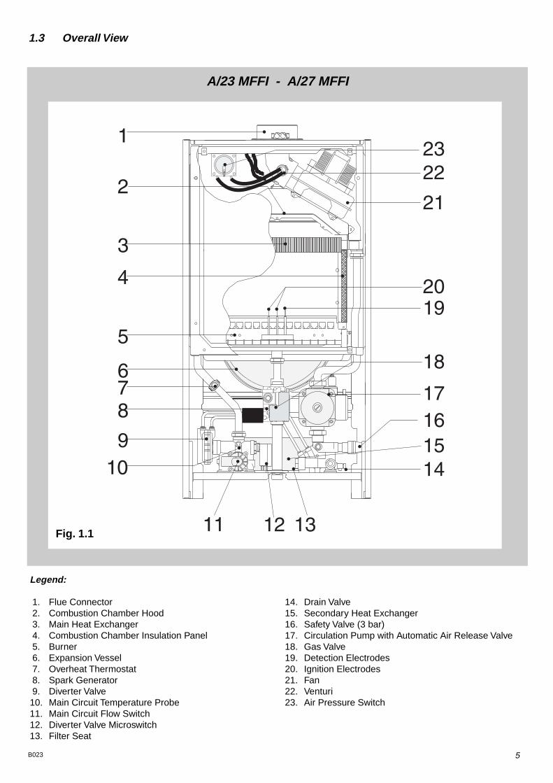
Legend:
1. Flue Connector2. Combustion Chamber Hood3. Main Heat Exchanger4. Combustion Chamber Insulation Panel5. Burner6. Expansion Vessel7. Overheat Thermostat8. Spark Generator9. Diverter Valve10. Main Circuit Temperature Probe11. Main Circuit Flow Switch12. Diverter Valve Microswitch13. Filter Seat
14. Drain Valve15. Secondary Heat Exchanger16. Safety Valve (3 bar)17. Circulation Pump with Automatic Air Release Valve18. Gas Valve19. Detection Electrodes20. Ignition Electrodes21. Fan22. Venturi23. Air Pressure Switch
Fig. 1.1
1.3 Overall View

6 B023
The technical information and instructions provided herein below are intendedfor the installer so that the unit may be installed correctly and safely.
The installation and initial start up of the boiler must be by a CORGI ApprovedInstaller in compliance with the installation standards currently in effect, as wellas with any and all local health and safety standards i.e. CORGI .
This appliance must be installed by a competent installer inaccordance with the 1984 Gas Safety (installation & use)Regulations (as amended)
The installation of this appliance must be in accordance with the relevantrequirements of the 1984 Gas Safety (installation & use) Regulations, the LocalBuilding Regulations, the current I.E.E. Wiring Regulations, the byelaws of thelocal water authority, and in Scotland, in accordance with the BuildingStandards (Scotland) Regulation and Health and Safety document No. 635“Electricity at work regs. 1989”.Installation should also comply with the following British Standard Codes ofPractice:
The appliance may be installed in any room or indoor area, although particularattention is drawn to the requirements of the current I.E.E. Wiring Regulations,and in Scotland, the electrical provisions of the Building Regulations applicablein Scotland, with respect to the installation of the combined appliance in a roomcontaining a bath or shower.Where a room-sealed appliance is installed in a room containing a bath orshower the boiler and any electrical switch or appliance control, utilisingmains electricity should be situated so that it cannot be touched by aperson using the bath or shower.The location must permit adequate space for servicing and air circulationaround the appliance as indicated in paragraph 2.4.The location must permit the provision of an adequate flue and termination.For unusual locations special procedures may be necessary.BS 6798-1987 gives detailed guidance on this aspect.A compartment used to enclose the appliance must be designed specifically forthis purpose. No specific ventilation requirements are needed for an installationwithin a cupboard This appliance is not suitable for outdoor installation.
The type C appliances (in which the combustion circuit, air vent intakeand combustion chamber are air-tight with respect to the room in whichthe appliance is installed) can be installed in any type of room.There are no limitations with respect to ventilation and the volume of the roomitself. The boiler must be installed on a solid, permanent wall to prevent accessto the electrical parts (when live) through the aperture on the back frame.
2.1 Reference Standards
2.2 Siting the Appliance
Low pressure pipes BS 6891 1988Boilers of rated inputnot exceeding 60 kW BS 6798 1987Forced circulation hot water system BS 5449 1990Installation of gas hot watersupplies for domestic purposes( 2nd family gases) BS 5546 1990Flues BS 5440-1 1990Air supply BS 5440-2 1989
2. INSTALLATION

7B023
Legend:A = Central Heating Flow (3/4”)B = Domestic Hot Water Outlet (1/2”)C = Gas Inlet (3/4”)D = Domestic Cold Water Inlet (1/2”)E = Central Heating Return (3/4”)
2.3 Overall Dimensions
890
365
(A-B-D-E)
(C)
465
In order to allow for access to the interior of the boiler for maintenance purposes, theboiler must be installed in compliance with the minimum clearances indicated in thediagram below.
400
300
450
60 60
40 50 60 70 80
C C
2.4 Clearances
A/23 MFFI - A/27 MFFI
Fig. 2.1
Fig. 2.2

8 B023
Fasten the boiler in place using the template and anchors supplied with theunit. It is highly recommended that a spirit level be used to position the boiler sothat it is perfectly level.For additional information, please consult the instructions contained in theconnection kit and the flue kit.
For safety purposes, have a competent person carefully check the electricalsystem in the property, as the manufacturer will not be held liable for damagecaused by the failure to earth the appliance properly or by anomalies in thesupply of power. Make sure that the residential electrical system is adequate forthe maximum power absorbed by the unit, which is indicated on the rating plate.In addition, check that the section of cabling is appropriate for the powerabsorbed by the boiler.
The boiler operates with alternating current, as indicated in the technical datatable (1.2), where the maximum absorbed power is also indicated. Make surethat the connections for the neutral and live wires correspond to the indicationsin the diagram. The appliance electrical connections are situated on the reverseof the control panel (see the servicing manual for further information)
2.5 Mounting the Appliance
2.6 Electrical Connection
Important!In the event that the power supply cord must be changed, replace it with onewith the same specifications. Make the connections to the terminal boardlocated within the control panel, as follows:- The yellow-green wire should be connected to the terminal marked with the
earth symbol; make sure to re-use the ferrule mounted on the other supplycord;
- The blue wire should be connected to the terminal marked “N”;- The brown wire should be connected to the terminal marked “L”.Note: The diagrams for the electrical system are indicated in section 2.11.
Warning, this appliance must be earthed.External wiring to the appliance must be carried out by a qualified technicianand be in accordance with the current I.E.E. Regulations and applicable localregulations. The EuroCombi range of boilers are supplied for connection to a230 V~ 50 Hz supply.The supply must be fused at 3 A.The method of connection to the electricity supply must facilitate completeelectrical isolation of the appliance, by the use of a fused double pole isolatorhaving a contact separation of at least 3 mm in all poles or alternatively, bymeans of a 3 A fused three pin plug and unswitched shuttered socket outletboth complying with BS 1363.The point of connection to the electricity supply must be readily accessible andadjacent to the appliance unless the appliance is installed in a bathroom whenthis must be sited outside the bathroom.
2.7 Gas Connection The local gas region contractor connects the gas meter to the service pipe.If the gas supply for the boiler serves other appliances ensure that an adequatesupply is available both to the boiler and the other appliances when they are inuse at the same time.Pipe work must be of an adequate size. Pipes of a smaller size than the boilerinlet connection should not be used.
Fig. 2.3

9B023
2.9 Water Connections
Legend
A = Central Heating FlowB = Domestic Hot Water OutletC = Gas InletD = Domestic Cold Water InletE = Central Heating ReturnI = Safety Valve
Central HeatingDetailed recommendations are given in BS 6798:1987 and BS 5449-1:1990,the following notes are given for general guidance.Pipe Work:
Copper tubing to BS EN 1057:1996 is recommended for water pipes. Jointingshould be either with capillary soldered or compression fittings.Where possible pipes should have a gradient to ensure air is carried naturallyto air release points and water flows naturally to drain taps.The appliance has a built-in automatic air release valve, however it should be ensured as far as possible that the appliance heat exchanger is not a natural collecting point for air.Except where providing useful heat, pipes should be insulated to prevent heatloss and avoid freezing.Particular attention should be paid to pipes passing through ventilated spacesin roofs and under floors.
By-pass:The appliance includes an automatic by-pass valve, which protects the main heat exchanger in case of reduced or interrupted water circulation through the heating system, due to the closing of thermostatic valves or cock-type valves within the system.
System Design:This boiler is suitable only for sealed systems.
Drain Cocks:These must be located in accessible positions to permit the draining of the whole system. The taps must be at least 15mm nominal size and manufactured in accordance with BS 2870:1980.
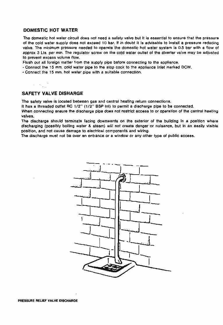
Safety Valve Discharge:The discharge should terminate facing downwards on the exterior of the building in a position where discharging (possibly boiling water & steam) will not create danger or nuisance, but in an easily visible position, and not causedamage to electrical components and wiring.The discharge must not be over an entrance or a window or any other type of
A
C
B D E
I
A/23 MFFI - A/27 MFFI
Fig. 2.4

10 B023
public access.Air Release Points:
These must be fitted at all high points where air naturally collects and must be sited to facilitate complete filling of the system.The appliance has an integral sealed expansion vessel to accommodate the increase of water value when the system is heated.It can accept up to 7 l (1.5 gal) of expansion water. If the heating circuit has an unusually high water content, calculate the total expansion and add an additional sealed expansion vessel with adequate capacity.
Mains Water Feed - Central Heating:There must be no direct connection to the mains water supply even through anon-return valve, without the approval of the Local Water Authority.
Filling:A temporary method for initially filling the system and replacing lost water during servicing in accordance with Water Supply Byelaw 14 must be provided.
Domestic WaterThe domestic water must be in accordance with the relevant recommendationof BS 5546:1990. Copper tubing to BS EN 1057:1996 is recommended forwater carrying pipe work and must be used for pipe work carrying drinkingwater.
2.9 Flue Connections Flue SystemThe provision for satisfactory flue termination must be made as describedin BS 5440-1.The appliance must be installed so that the flue terminal is exposed to outdoor air.The terminal must not discharge into another room or space such as anouthouse or lean-to.It is important that the position of the terminal allows a free passage of airacross it at all times.The terminal should be located with due regard for the damage ordiscolouration that might occur on buildings in the vicinity.In cold or humid weather water vapour may condense on leaving the flueterminal.The effect of such "steaming" must be considered.If the terminal is less than 2 metres above a balcony, above ground or above aflat roof to which people have access, then a suitable terminal guard must befitted. When ordering a terminal guard, quote the appliance model number.A suitable terminal guard is available from:TOWER FLUE COMPONENTSMorley RoadTonbridgeKent TN9 1RAThe minimum acceptable spacing from the terminal to obstructions andventilation openings are specified in Fig. 2.5.
Residual Head of the Boiler
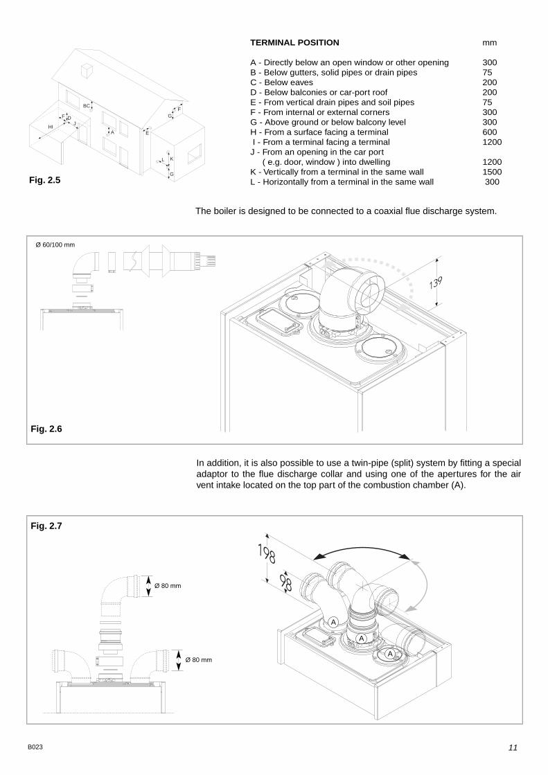
TERMINAL POSITION mm
A - Directly below an open window or other opening 300B - Below gutters, solid pipes or drain pipes 75C - Below eaves 200D - Below balconies or car-port roof 200E - From vertical drain pipes and soil pipes 75F - From internal or external corners 300G - Above ground or below balcony level 300H - From a surface facing a terminal 600I - From a terminal facing a terminal 1200J - From an opening in the car port
( e.g. door, window ) into dwelling 1200K - Vertically from a terminal in the same wall 1500L - Horizontally from a terminal in the same wall 300
11B023
A
BC
D
E
F
G
J
K
HI
L
GF
Fig. 2.5
Ø 60/100 mm
The boiler is designed to be connected to a coaxial flue discharge system.
A
Ø 80 mm
Ø 80 mm
In addition, it is also possible to use a twin-pipe (split) system by fitting a specialadaptor to the flue discharge collar and using one of the apertures for the airvent intake located on the top part of the combustion chamber (A).
A
A
Fig. 2.7
Fig. 2.6

12 B023
This procedure must be done as follows:1 - Remove the air vent intake you want to use, in the area indicated in
Fig. 2.8, by breaking the perforated ring.2 - Use a tool to grasp the lid and remove it completely.3 - Clean any burrs or sharp edges with a knife or an appropriate tool.
In Fig. 2.10 below, several different types of flue systems are shown.For additional information regarding the flue accessories, please consult theFlue Pipe Accessories manual.
A
Fig. 2.8 Fig. 2.9
Fig. 2.10
13B023
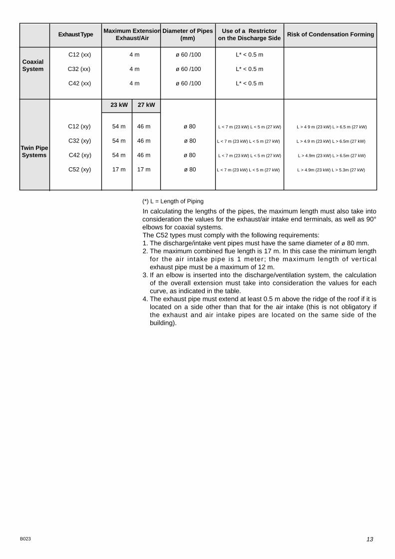
In calculating the lengths of the pipes, the maximum length must also take intoconsideration the values for the exhaust/air intake end terminals, as well as 90°elbows for coaxial systems.The C52 types must comply with the following requirements:1. The discharge/intake vent pipes must have the same diameter of ø 80 mm.2. The maximum combined flue length is 17 m. In this case the minimum length
for the air intake pipe is 1 meter ; the maximum length of ver ticalexhaust pipe must be a maximum of 12 m.
3. If an elbow is inserted into the discharge/ventilation system, the calculationof the overall extension must take into consideration the values for eachcurve, as indicated in the table.
4. The exhaust pipe must extend at least 0.5 m above the ridge of the roof if it islocated on a side other than that for the air intake (this is not obligatory ifthe exhaust and air intake pipes are located on the same side of thebuilding).
(*) L = Length of Piping
C12 (xx) 4 m ø 60 /100 L* < 0.5 mCoaxialSystem C32 (xx) 4 m ø 60 /100 L* < 0.5 m
C42 (xx) 4 m ø 60 /100 L* < 0.5 m
23 kW 27 kW
C12 (xy) 54 m 46 m ø 80 L < 7 m (23 kW) L < 5 m (27 kW) L > 4 9 m (23 kW) L > 6.5 m (27 kW)
C32 (xy) 54 m 46 m ø 80 L < 7 m (23 kW) L < 5 m (27 kW) L > 4.9 m (23 kW) L > 6.5m (27 kW)
Twin PipeSystems C42 (xy) 54 m 46 m ø 80 L < 7 m (23 kW) L < 5 m (27 kW) L > 4.9m (23 kW) L > 6.5m (27 kW)
C52 (xy) 17 m 17 m ø 80 L < 7 m (23 kW) L < 5 m (27 kW) L > 4.9m (23 kW) L > 5.3m (27 kW)
Exhaust Type Diameter of Pipes(mm)
Use of a Restrictoron the Discharge Side
Risk of Condensation FormingMaximum ExtensionExhaust/Air
14 B023
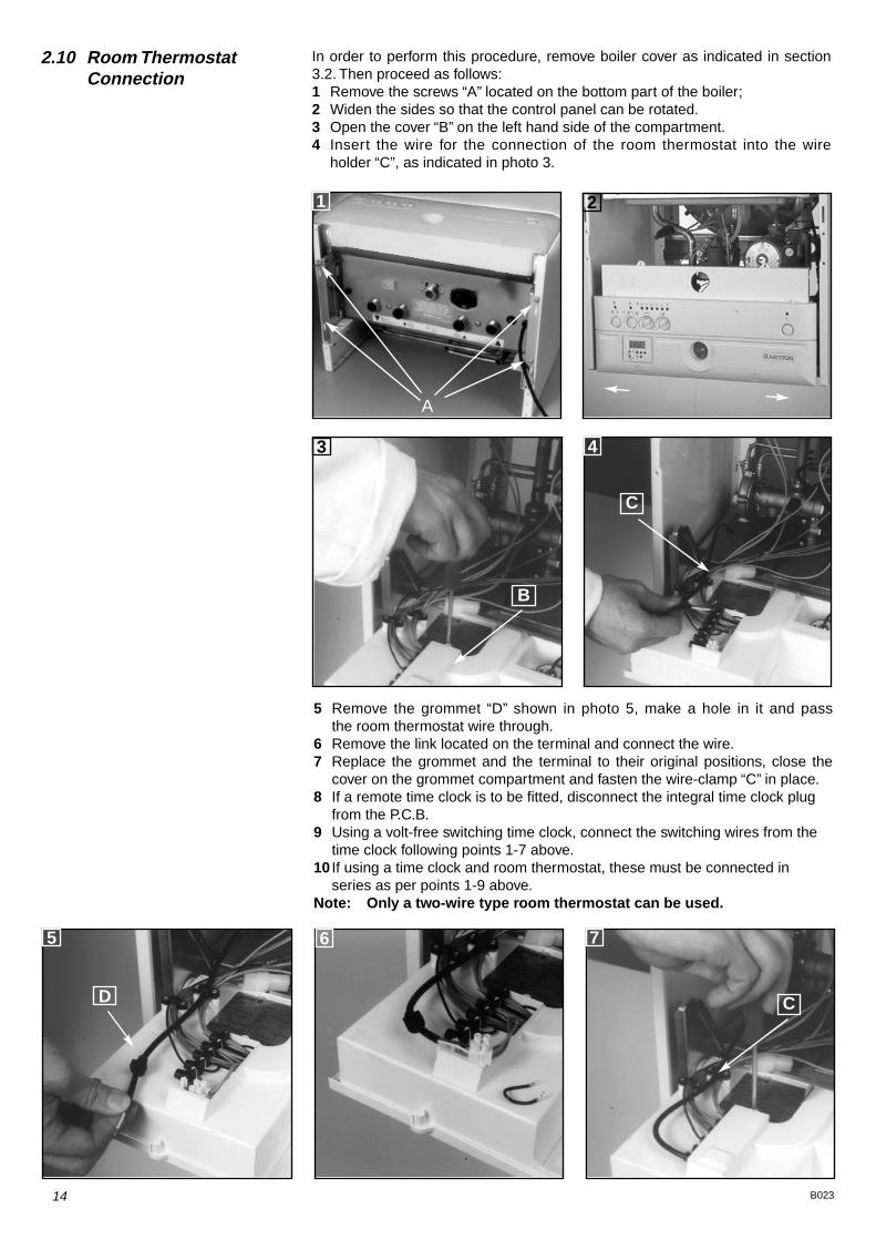
5 Remove the grommet “D” shown in photo 5, make a hole in it and passthe room thermostat wire through.
6 Remove the link located on the terminal and connect the wire.7 Replace the grommet and the terminal to their original positions, close the
cover on the grommet compartment and fasten the wire-clamp “C” in place.8 If a remote time clock is to be fitted, disconnect the integral time clock plug
from the P.C.B.9 Using a volt-free switching time clock, connect the switching wires from the
time clock following points 1-7 above.10 If using a time clock and room thermostat, these must be connected in
series as per points 1-9 above.Note: Only a two-wire type room thermostat can be used.
2.10 Room Thermostat Connection
3 4
5 6 7
D
C
B
C
1
A
2
In order to perform this procedure, remove boiler cover as indicated in section3.2. Then proceed as follows:1 Remove the screws “A” located on the bottom part of the boiler;2 Widen the sides so that the control panel can be rotated.3 Open the cover “B” on the left hand side of the compartment.4 Insert the wire for the connection of the room thermostat into the wire
holder “C”, as indicated in photo 3.

15B023
2.11 Electrical Diagram Legend:
AT = High Voltage P.C.B.BT = Low Voltage P.C.B.B = Flame Failure L.E.D.C = Insufficient Water Pressure L.E.D.D = Water Temperature Indicator L.E.D.sE = Overheat Thermostat Warning L.E.D.F = System Reset ButtonG = Selector Knob for Operating ModeH = Domestic Hot Water Temp. AdjustmentI = Central Heating Temp. AdjustmentJ = Wire Connector for Room ThermostatK = Connector for Total Check SystemM = Anti-cycling Device Adjustment for HeatingN = Soft-light AdjustmentO = Max Heating Temperature AdjustmentP = Time Clock Connection Q = On/Off L.E.D.R = On/Off SwitchS = Interface Wire for P.C.B.sT = Relay Motorised ValveU = Ignitor RelayV = Gas Valve RelayW = Fan RelayX = Circulation Pump RelayAa = Adaptor (British Gas use only)Y = Selector TCS2
A01 = Air Pressure SwitchA02 = FanA03 = Gas ValveA04 = IgnitorA05 = Motorised ValveA06 = Circulation PumpA07 = Flame DetectorA08 = Earth TerminalA09 = Flame Detection CircuitA10 = Flame Indicator L.E.D.A11 = TransformerA12 = Filter
B01 = Over Heat ThermostatB02 = Room ThermostatB03 = Gas Valve ModulatorB05 = Heating SensorB06 = Pressure Switch for Heating CircuitB07 = Microswitch for Diverter Valve
Colours
Gry = GreyRd = RedBl = BlueGrn/Yll = Yellow/Green Wh = WhiteBrn = BrownBlk = BlackWh/Rd = White/Red

16 B023
A/23 MFFI - A/27 MFFI
EX
C-M
I/FF
I
8
A/23 MFFI - A/27 MFFI

2.12 Water Circuit Diagram
17B023
A/23 MFFI - A/27 MFFI Legend1. Air Pressure Switch2. Fan3. Main Heat Exchanger4. Main Burner 5. Ignition Electrodes
Detection Electrode6. Gas Valve7. Overheat Thermostat 8. Main Circuit Temperature Probe9. Diverter Valve10. Main Circuit Flow Switch including
Safety Pressure Switch forPrimary Circuit
11. Automatic By-pass 12. Microswitch for Diverter Valve13. Secondary Heat Exchanger14. Domestic Water Inlet Filter15. Boiler Drain Valve16. Safety Valve17. Water Pressure Gauge18. Circulation Pump with Automatic
Air Release Valve19. Expansion Vessel3 COMMISSIONING
3.1 Initial Preparation Preliminary electrical system checks to ensure electrical safety must be carriedout by a competent person i.e. polarity, earth continuity, resistance to earth andshort circuit.
Filling the Heating System:Remove the panels of the case and lower the control panel (see point 3.2. for further information).Open the central heating flow and return cocks supplied with the connection kit.Unscrew the cap on the automatic air release valve one full turn and leave open permanently.Close all air release valves on the central heating system.Gradually open valve(s) at the filling point (filling-loop) connection to the central heating system until water is heard to flow, do not open fully.Open each air release tap starting with the lower point and close it only whenclear water, free of air, is visible.Purge the air from the pump by unscrewing anticlockwise the pump plug and also manually rotate the pump shaft in the direction indicated by the pump label to ensure the pump is free.Close the pump plug.Continue filling the system until at least 1 bar registers on the pressure gauge.Inspect the system for water soundness and remedy any leaks discovered.
Filling of the D.H.W. System:Close all hot water draw-off taps.Open the cold water inlet cock supplied with the connection kit.Open slowly each draw-off tap and close it only when clear water, free of bubbles, is visible
Gas Supply:Inspect the entire installation including the gas meter, test for soundness and purge, all as described in BS 6891:1988.Open the gas cock (supplied with the connection kit) to the appliance and check the gas connector on the appliance for leaks.
When the installation and filling are completed turn on the central heating

40 50 60 70 80
C C
3.3 Control Panel
A - Ignition Lockout Reset Button/Safety (Overheat)Thermostat ResetB - Ignition Lockout L.E.D.C - Selector Knob for Summer/Winter/Flue Analysis Modes*D - Low System Water Level L.E.D.E - Temperature Adjustment Knob for Domestic Hot WaterF - Heating System ThermometerG - Safety (Overheat)Thermostat Intervention L.E.D.H - Adjustment Knob for Heating TemperatureI - On/Off L.E.D.L - On/Off SwitchO - System Pressure Gauge
* Warning the flue analysis mode must only be selected by a qualified service engineer.
18 B023
3.2 Removing the Front Panel
A/23 MFFI - A/27 MFFI
21 F
To remove the front panel of the casing, proceed as follows:1. Remove the screw “F” located on the top edge of the panel.2. Lift and unhook the panel.
system (sect. 3.4) and run it until the temperature has reached the boileroperating temperature. The system must then be immediately flushed through.The flushing procedure must be in line with BS 7593:1992 Code of practice fortreatment of water in domestic hot water central heating systems.During this operation, we highly recommend the use of a central heatingflushing detergent (Fernox Superfloc or equivalent), whose function is todissolve any foreign matter that may be in the system.Substances different from these could create serious problems to thepump or other components.The use of an inhibitor in system such as Fernox MB-1 or equivalent is stronglyrecommended to prevent corrosion (sludge) damaging the boiler and system.Failure to carry out this procedure may invalidate the appliance warranty.

19B023
3.4 Initial Start-up The checks to be run before initial start-up are as follows:1. Make sure that:
- the screw on the automatic air valve has been loosened when thesystem is full;
- If the water pressure in the system is below 1 bar, bring it up to the appro-priate level;
-Check to see whether the gas cock is closed;-Make sure that the electrical connection has been made properly and that
the earth wire is connected to an efficient earthing system;- Supply power to the boiler by pressing the On/Off switch <L> - the L.E.D. “I”
will turn on - turn the selector knob “C” to the <winter> setting. This will startthe circulation pump. After 7 seconds, the boiler will signal a shut-down due to failure ignition. Leave the boiler as it is until all of the air hasbeen bled from the lines.
-Loosen the cap on the head of the pump to eliminate any air pockets;-Repeat the procedure for bleeding the radiators of air;-Open the taps for a brief period;-Check the system pressure and, if it has dropped, open the filling-loop
again to bring the pressure back up to 1 bar.2. Check the exhaust flue for the fumes produced by combustion.3. Make sure that all gate valves are open;4. Turn on the gas cock and check the seals on the connections, including the
one for the burner, making sure that the meter does not signal the passageof gas. Check the connections with a soap solution and eliminate any leaks.
5. Press the reset button “A” for the lighting system; the spark will light themain burner. If the burner does not light the first time, repeat the procedure.
6. Check the minimum and maximum pressure values for the gas going to theburner; adjust it if needed using the values indicated in the table insection 4.(See the relative section for burner pressure adjustment within the servicing manual).
3.5 OperationalAdjustments
The boiler was designed to make it easy to regulate and check the variousfeatures. To access the areas where the adjustment and control devices arelocated, simply remove the plugs by pressing from the inside, unscrew thescrews “A” and remove the bottom part of the instrument panel, rotating itupward.
Right hand side service panel also provides access to:- the power supply cord connector;- the fuses.Left hand side:- the potentiometer for regulating the ignition delay (anti-cycling) feature, which
can be set from 0 to 2 minutes (factory set at 1 minute);- the potentiometer for regulating the soft-light feature, the setting for which
can range from the minimum thermal power to the maximum:

20 B023
The boiler is designed to make it easy to analyse the combustion by-products.
Using the especially designed apertures, readings can be taken on thetemperature of the combustion by-products and of the combustion air, as wellas of the concentrations of O2 and CO2, etc.
The best maximum-power test conditions for the heating system are when theselector “C” is turned to the flue analysis setting.
The discharge/ventilation of the exhaust fumes can be monitored to check forlosses in general pressure in the system. This is done to eliminate the cause oflighting failure with the main burner not indicated by a shutdown status.With a differential manometer connected to the test socket on the combustionchamber, the DP value for the air pressure switch can be taken. The measuredvalue should not be less than 10 mbar under maximum thermal powerconditions (with the knob “C” on the flue test setting) in order for the unit tofunction properly and without interruption.
- the potentiometer for the maximum thermal power for the heating system,maximum thermal power setting (factory set at the maximum value, unlessindicated otherwise on the adhesive sticker located in proximity to thepotentiometer);
- The connection for the diagnostic device (TCS-TCS2).
G20 5.5 mm c.a.G25 4.5 mm c.a.G30-31 1.8 mm c.a.
The boiler is equipped with the following safety systems (see section 3.3 forreferences):1 - Ignition FailureThis control signals an ignition failure on the burner 7 seconds after a lightingfailure. The L.E.D. “B”.will turn on to signal the shutdown status.The system can be reset by pressing and releasing the button “A” afterchecking to make sure that the gas valve is open. Repeat this process until theburner lights.2 - Circulation FailureThis control signals that the safety pressure switch on the primary circuit hasnot sensed a pressure of at least 1 bar within 40 seconds of the activation ofthe circulation pump, it shuts off the boiler and lights the L.E.D. “D”. The systemcan be reset (after the pressure has been brought up to the proper level) byusing the On/Off switch “L”.3 - OverheatingThis control shuts off the boiler in the case where the primary circuit reaches atemperature in excess of 110°C. The L.E.D. “G” will come on to signal this shut
3.6 Combustion Analysis
3.7 Fume Discharge Monitoring
3.8 Boiler Safety Systems

21B023
off status. After the system has been allowed to cool, the system can be resetby pressing the button “A”.4 - Limescale Build-upThis is an indirect control (actuated through the regulation of the temperature inthe primary heat exchanger) on the formation of limescale in the secondaryheat exchanger. Regardless of the flow rate and the temperature in the circuitfor the domestic hot water, the temperature is limited to 62°C.5 - Safety Shut-offAt the start of every lighting phase, the P.C.B. performs a series of internalcontrols. If a malfunction occurs, the boiler will shutdown until the problem hasbeen resolved.
3.9 Draining the System Draining the heating system.The heating system must be emptied as follows:- Turn off the boiler;- Open the drain valve for the system and place a container below to catch the
water that comes out;- Empty the system at the lowest points (where present). If you plan on not
using the heating system for an extended period of time, it is recommendedthat you add antifreeze with an ethylene glycol base to the water in theheating lines and radiators if the ambient temperature drops below 0°C duringthe winter.This makes repeated draining of the entire system unnecessary.
Draining the domestic hot water system.Whenever there is the danger of the temperature dropping below the freezingpoint, the domestic hot water system must be drained as follows:- Turn off the general water valve for the household plumbing system;- Turn on all the hot and cold water taps;- Empty the remaining water from the lowest points in the system (where
present).
The outlet pressure of the gas cock is obtained by completely loosening thescrew on the solenoid. The maximum pressure of the gas to the burner will beequal to the nominal delivery pressure minus the head loss within the gasvalve.
4. GAS ADJUSTMENTS
(1mbar = 10,197 column of water)
CATEGORY II2H3+ Methane GasG20
Liquid Butane GasG30
Liquid Propane GasG31
Lower Wobbe Index (15°C;1013mbar) MJ/m3h 45.67 80.58 70.69Nominal Delivery Pressure mbar 20 30 37Minimum Delivery Pressure mbar 17 20 25
A/23 MFFIMain Burner: n. 13 jets (ø) mm 1.,25 0.72 0.72Consumption (15°C; 1013mbar) mc/h 2.72 ---- ----Consumption (15°C; 1013mbar) Kg/h ---- 2.02 2.02Gas Cock Outlet Pressuremin - max mbar 11.4- 2.0 27.5 (*) - 5.2 35.0 (*) - 7.0
A/27 MFFI Main Burner: n. 15 jets (ø) 1.25 0.72 0.72Consumption (15°C; 1013mbar) mc/h 3.16 ---- ----Consumption (15°C; 1013mbar) Kg/h ---- 2.35 2.32Gas Cock Outlet Pressure:max - min mbar 11.6-2.2 (*) - 4.8 (*) - 6.0

22 B023
4.1 Changing the Type ofGas
The boiler can be converted to use either methane (natural) gas (G20) orLPG (G30 - G31) by an Authorised Service Centre.The operations that must be performed are the following:1. Replace the jets on the main burner (see table in section 4);2. Adjust the maximum and minimum thermal capacity values for the boiler
(see table in section 4);3. Replace the gas rating plate;4. Adjust the maximum thermal power setting;
5. Adjust the soft-light feature;6. Adjust the ignition delay feature for the heating system (can be set from
0 to 2 mins.).
CATEGORY II2H3+ Methane Gas Liquid Butane Gas Liquid Propane Gas
G20 G30 G31
Recommended Soft-Light Pressure(mbar) 5-5.5 17 - 18 18 - 19
It is recommended that the following checks be made on the boiler atleast once a year:1 - Check the seals for the water connections; replacement of any faulty seals.2 - Check the gas seals; replacement of any faulty gas seals.3 - Visual check of the entire unit.4 - Visual check of the combustion process and cleaning of the burners if
needed.5 - If called for by check no. 3, dismantling and cleaning of the combustion
chamber.6 - If called for by check no. 4, dismantling and cleaning of the injectors.7 - Visual check of the primary heat exchanger:
- check for overheating in the blade assembly;- clean the exhaust fan if needed.
8 - Adjustment of the flow rate of the gas: flow rate for lighting, partial load and full load.
9 - Check of the heating safety systems:- safety device for maximum temperature;- safety device for maximum pressure.
10 - Check of the gas safety systems:- safety device for lack of gas or flame (detection electrode);- safety device for gas cock.
11 - Check of the electrical connection (make sure it complies with theinstructions in the manual).
12 - Check of domestic hot water production efficiency (delivery rate and tem-perature)
13 - Check of the general performance of the unit.14 - General check of the discharge/ventilation of the combustion by-
products.
5. MAINTENANCE

6. MISCELLANEOUS
6.1 Wiring Dia gram f or Two Heating Zones
V4043HVALVE
BROWN 8
BLUE 2
GREY 9
ORANGE 10
GREEN/YELLOW 3
Hone
ywel
l ST
699B
100
26
3N
LLi
nk L
-5-8
ST 6
400/
ST 6
300
ST 6
200
34
NL
Dray
ton
Tem
pus
73
4N
L
Hors
tman
n 42
5, 5
25, 5
271
4E
NL
Link
L-2
-5
Land
is &
Gyr
RW
B23
4N
LG
lowwo
rm M
aste
rmin
d
Land
is &
Gyr
RW
B20
34
NL
Micr
ogyr
Potte
rton
Min
imin
der
34
NL
Potte
rton
EP20
00/3
000
-3
4N
LLi
nk L
-5
EP20
01/3
001
Rand
all 1
02/1
02 E
12
E5
6Li
nk 3
-6
Rand
all 4
033
42
E7
6Li
nk 1
-6
Rand
all 7
01, 7
023
1E
NL
Link
L-6
-5
Sang
amo
M5
18
E4
3Li
nk 1
-6
Sang
amo
410
Form
11
8E
43
Link
3-6
PR
OG
RA
MM
ER
64
32
1
Pegl
er S
unvic
25
EN
LSP
50/
100
(Lin
k L-
3)
Switc
hmas
ter
14
NL
Sym
phon
y, So
nata
Switc
hmas
ter 4
00, 6
003
1N
L
SWIT
CHM
ASTE
R 80
5, 9
003
1N
L
Sunv
ic ET
145
17
4E
12
Link
2-3
-6
Sunv
ic DH
P 22
016
3E
12
Towe
rchr
on F
P6
10
21
Link
1-5
/4-7
-9
Towe
rchr
on M
P6
10
21
Link
1-4
/6-1
1
Towe
rchr
on 2
000
HW
HTG
NL
ON
ON
ACL
LS52
2, L
S722
34
NL
Rand
all 9
22, 9
723
6E
NL
Link
L-2
-5
Rand
all 3
020
P4
2E
NL
and
3060
PR
OG
RA
MM
ER
64
32
1
A/27
MFF
I - A
/27 M
FFI
EN
LGe
nus 2
3-27-3
0 MFF
IE
NL
Genu
s 27 R
FFI S
ystem
EN
L
BO
ILE
R
910
32
240VMAINS INPUT (3 AMP)
L 1
N 2
E 3
• 1
• 2
• 3
• 4
• 5
• 6
• 7
• 8
• 9
• 10
TYPICALJUNCTION BOX
T6360BROOM
THERMOSTAT
1 6
3 8
2 2
ZONE 2
V4043HVALVE
BROWN 5
BLUE 2
GREY 9
ORANGE 10
GREEN/YELLOW 3
T6360BROOM
THERMOSTAT
1 4
3 5
2 2
ZONE1 ZO
NE
1Z
ON
E 1
ZO
NE
2Z
ON
E 2
1
BOILER ELECTRICAL SUPPLY CABLE
Remove internal time clock plugfrom the the P.C.B. then connectroom stat terminal block on thereverse of the boiler control panel(see section 2.10) to 9 + 10 onthe junction box.
If a room thermostat is not required on Zone 1, insert a linkbetween 4 + 5 on the junction box.
If a room thermostat is not required on Zone 2, insert a linkbetween 6 + 8 on the junction box.
V4043HVALVE
BROWN 8
BLUE 2
GREY 9
ORANGE 10
GREEN/YELLOW 3
Hone
ywel
l ST
699B
100
26
3N
LLi
nk L
-5-8
ST 6
400/
ST 6
300
ST 6
200
34
NL
Dray
ton
Tem
pus
73
4N
L
Hors
tman
n 42
5, 5
25, 5
271
4E
NL
Link
L-2
-5
Land
is &
Gyr
RW
B23
4N
LG
lowwo
rm M
aste
rmin
d
Land
is &
Gyr
RW
B20
34
NL
Micr
ogyr
Potte
rton
Min
imin
der
34
NL
Potte
rton
EP20
00/3
000
-3
4N
LLi
nk L
-5
EP20
01/3
001
Rand
all 1
02/1
02 E
12
E5
6Li
nk 3
-6
Rand
all 4
033
42
E7
6Li
nk 1
-6
Rand
all 7
01, 7
023
1E
NL
Link
L-6
-5
Sang
amo
M5
18
E4
3Li
nk 1
-6
Sang
amo
410
Form
11
8E
43
Link
3-6
PR
OG
RA
MM
ER
64
32
1
Pegl
er S
unvic
25
EN
LSP
50/
100
(Lin
k L-
3)
Switc
hmas
ter
14
NL
Sym
phon
y, So
nata
Switc
hmas
ter 4
00, 6
003
1N
L
SWIT
CHM
ASTE
R 80
5, 9
003
1N
L
Sunv
ic ET
145
17
4E
12
Link
2-3
-6
Sunv
ic DH
P 22
016
3E
12
Towe
rchr
on F
P6
10
21
Link
1-5
/4-7
-9
Towe
rchr
on M
P6
10
21
Link
1-4
/6-1
1
Towe
rchr
on 2
000
HW
HTG
NL
ON
ON
ACL
LS52
2, L
S722
34
NL
Rand
all 9
22, 9
723
6E
NL
Link
L-2
-5
Rand
all 3
020
P4
2E
NL
and
3060
PR
OG
RA
MM
ER
64
32
1
A/27
MFF
I - A
/27 M
FFI
EN
LGe
nus 2
3-27-3
0 MFF
IE
NL
Genu
s 27 R
FFI S
ystem
EN
L
BO
ILE
R
910
32
240VMAINS INPUT (3 AMP)
L 1
N 2
E 3
• 1
• 2
• 3
• 4
• 5
• 6
• 7
• 8
• 9
• 10
TYPICALJUNCTION BOX
T6360BROOM
THERMOSTAT
1 6
3 8
2 2
ZONE 2
V4043HVALVE
BROWN 5
BLUE 2
GREY 9
ORANGE 10
GREEN/YELLOW 3
T6360BROOM
THERMOSTAT
1 4
3 5
2 2
ZONE1 ZO
NE
1Z
ON
E 1
ZO
NE
2Z
ON
E 2
1
BOILER ELECTRICAL SUPPLY CABLE
Remove internal time clock plugfrom the the P.C.B. then connectroom stat terminal block on thereverse of the boiler control panel(see section 2.10) to 9 + 10 onthe junction box.
If a room thermostat is not requied on Zone 1, insert a linkbetween 4 + 5 on the junction box.
If a room thermostat is not requied on Zone 2, insert a linkbetween 6 + 8 on the junction box.
23 B023
Bas
ed o
n H
oney
wel
l con
trol
s

24B023
6.2 Wiring Diagram for Connection to Ariston Unvented Cylinder
V4043HVALVE
BROWN 8
BLUE 2
GREY 9
ORANGE 10
GREEN/YELLOW 3
Hone
ywel
l ST
699B
100
26
3N
LLi
nk L
-5-8
ST 6
400/
ST 6
300
ST 6
200
34
NL
Dray
ton
Tem
pus
73
4N
L
Hors
tman
n 42
5, 5
25, 5
271
4E
NL
Link
L-2
-5
Land
is &
Gyr
RW
B23
4N
LG
lowwo
rm M
aste
rmin
d
Land
is &
Gyr
RW
B20
34
NL
Micr
ogyr
Potte
rton
Min
imin
der
34
NL
Potte
rton
EP20
00/3
000
-3
4N
LLi
nk L
-5
EP20
01/3
001
Rand
all 1
02/1
02 E
12
E5
6Li
nk 3
-6
Rand
all 4
033
42
E7
6Li
nk 1
-6
Rand
all 7
01, 7
023
1E
NL
Link
L-6
-5
Sang
amo
M5
18
E4
3Li
nk 1
-6
Sang
amo
410
Form
11
8E
43
Link
3-6
PR
OG
RA
MM
ER
64
32
1
Pegl
er S
unvic
25
EN
LSP
50/
100
(Lin
k L-
3)
Switc
hmas
ter
14
NL
Sym
phon
y, So
nata
Switc
hmas
ter 4
00, 6
003
1N
L
SWIT
CHM
ASTE
R 80
5, 9
003
1N
L
Sunv
ic ET
145
17
4E
12
Link
2-3
-6
Sunv
ic DH
P 22
016
3E
12
Towe
rchr
on F
P6
102
1Li
nk 1
-5/4
-7-9
Towe
rchr
on M
P6
102
1Li
nk 1
-4/6
-11
Towe
rchr
on 2
000
HW
HTG
NL
ON
ON
ACL
LS52
2, L
S722
34
NL
Rand
all 9
22, 9
723
6E
NL
Link
L-2
-5
Rand
all 3
020
P4
2E
NL
and
3060
PR
OG
RA
MM
ER
64
32
1
A/27
MFF
I - A
/27 M
FFI
EN
LGe
nus 2
3-27-3
0 MFF
IE
NL
Genu
s 27 R
FFI S
ystem
EN
L
BO
ILE
R
910
32
240VMAINS INPUT (3 AMP)
L 1
N 2
E 3
• 1
• 2
• 3
• 4
• 5
• 6
• 7
• 8
• 9
• 10
TYPICALJUNCTION BOX
T6360BROOM
THERMOSTAT
1 6
3 8
2 2
ZONE 2
V4043HVALVE
BROWN 5
BLUE 2
GREY 9
ORANGE 10
GREEN/YELLOW 3
T6360BROOM
THERMOSTAT
1 4
3 5
2 2
ZONE1 ZO
NE
1Z
ON
E 1
ZO
NE
2Z
ON
E 2
1
BOILER ELECTRICAL SUPPLY CABLE
Remove internal time clock plugfrom the the P.C.B. then connectroom stat terminal block on thereverse of the boiler control panel(see section 2.10) to 9 + 10 onthe junction box.
If a room thermostat is not requied on Zone 1, insert a linkbetween 4 + 5 on the junction box.
If a room thermostat is not requied on Zone 2, insert a linkbetween 6 + 8 on the junction box.
Hone
ywel
l ST
699B
100
26
3N
LLi
nk L
-5-8
ST 6
400/
ST 6
300
ST 6
200
34
NL
Dray
ton
Tem
pus
73
4N
L
Hors
tman
n 42
5, 5
25, 5
271
4E
NL
Link
L-2
-5
Land
is &
Gyr
RW
B23
4N
LG
lowwo
rm M
aste
rmin
d
Land
is &
Gyr
RW
B20
34
NL
Micr
ogyr
Potte
rton
Min
imin
der
34
NL
Potte
rton
EP20
00/3
000
-3
4N
LLi
nk L
-5
EP20
01/3
001
Rand
all 1
02/1
02 E
12
E5
6Li
nk 3
-6
Rand
all 4
033
42
E7
6Li
nk 1
-6
Rand
all 7
01, 7
023
1E
NL
Link
L-6
-5
Sang
amo
M5
18
E4
3Li
nk 1
-6
Sang
amo
410
Form
11
8E
43
Link
3-6
PR
OG
RA
MM
ER
64
32
1
Pegl
er S
unvic
25
EN
LSP
50/
100
(Lin
k L-
3)
Switc
hmas
ter
14
NL
Sym
phon
y, So
nata
Switc
hmas
ter 4
00, 6
003
1N
L
SWIT
CHM
ASTE
R 80
5, 9
003
1N
L
Sunv
ic ET
145
17
4E
12
Link
2-3
-6
Sunv
ic DH
P 22
016
3E
12
Towe
rchr
on F
P6
102
1Li
nk 1
-5/4
-7-9
Towe
rchr
on M
P6
102
1Li
nk 1
-4/6
-11
Towe
rchr
on 2
000
HW
HTG
NL
ON
ON
ACL
LS52
2, L
S722
34
NL
Rand
all 9
22, 9
723
6E
NL
Link
L-2
-5
Rand
all 3
020
P4
2E
NL
and
3060
PR
OG
RA
MM
ER
64
32
1
A/27
MFF
I - A
/27 M
FFI
EN
LGe
nus 2
3-27-3
0 MFF
IE
NL
Genu
s 27 R
FFI S
ystem
EN
L
BO
ILE
R
910
32
• 1
• 2
• 3
• 4
• 5
• 6
• 7
• 8
• 9
• 10
TYPICALJUNCTION BOX
1
BOILER ELECTRICAL SUPPLY CABLE
Remove internal time clock plugfrom the the P.C.B. then connectroom stat terminal block on thereverse of the boiler control panel(see section 2.10) to 9 + 10 onthe junction box.
T6360BROOM
THERMOSTAT
1 4
3 5
2 2
V4043HHEATING VALVE
BROWN 5
BLUE 2
GREY 9
ORANGE 10
GREEN/YELLOW 3
V4043HHOT WATER VALVE
BROWN 8
BLUE 2
GREY 9
ORANGE 10
GREEN/YELLOW 3
1 C/P
Cylinderthermostat
Thermalcut-out
1 8
6
Notused
P
2
1 C/P2
240VMAINS INPUT (3 AMP)
L 1
N 2
E 3
Bas
ed o
n H
oney
wel
l con
trol
s

NOTES
25 B023

26B023
NOTES

27 B023

Manufacturer: Merloni TermoSanitari SpA - Italy
Commercial subsidiary: MTS (GB) LIMITEDMTS BuildingHughenden Avenue,High WycombeBucks HP13 5FTTelephone: (01494) 755600 -Fax: (01494) 459775Technical Service Hotline: (01494) 539579 C
od.2
3 99
84
1260
112
- B
023
STA
MPA
:Azi
enda
Gra
fica
BIE
FF
E s
rl -
Rec
anat
i

A/23 MFFI - A/27 MFFIG.C.N. 47-116-10 / 47-116-12Servicing InstructionsType C BoilersLEAVE THESE INSTRUCTIONSADJACENT TO THE GAS METER

2 B029
Page No.
1. SERVICING INSTRUCTIONS
1.1 Replacement of Parts 3
1.2 To Gain General Access- Removing the Front Panel 3- Removing the Side Panels 4- To Lower the Control Panel 4
1.3 Access to the Combustion Chamber- Removing the Sealed Combustion Chamber 5- Removing the Burner and Injectors 5- Removing the Electrodes 6- Removing the Main Heat Exchanger 7- Removing the Air Pressure Switch 7- Removing the Venturi Device 8- Removing the Fan 8
1.4 Servicing and Removal of the Gas Valve- Setting Gas Pressure 9- Removing the Spark Ignitor 11- Removing the Gas Valve 12
1.5 Access to the Hydraulic Circuit- Removing the D.H.W. (Secondary) Exchanger 12- Removing the Safety Valve 13- Removing the Automatic Air Vent 13- Removing the Main Flow Circuit Switch 13- Removing the Pump 14- Removing the Pressure Gauge 14- Removing the Expansion Vessel 15- Removing the Overheat Thermostat 15- Removing the Heating Temperature Sensor (N.T.C.) 15
1.6 Access to the Control System- Checking the Fuses 16- Removing the Time Clock 16- Removing the P.C.B.s 17
2. FAULT FINDING
2.1 Fault Finding Guide (Flow-chart) 182.2 Fault Finding Using the Total Check System 23
3. ELECTRICAL DIAGRAMS
3.1 Electrical Connection 243.2 Functional Flow Connection 25
4. SHORT SPARE PARTS LIST 26
TABLE OF CONTENTS

3B029
1. SERVICING
INSTRUCTIONS
The life of individual components vary and they will need servicing orreplacing as and when faults develop.The fault finding sequence chart in chapter 2 will help to locate whichcomponent is the cause of any malfunction, and instructions for removal,inspection and replacement of the individual parts are given in the followingpages.
1.1 Replacementof Parts
1.2 To Gain GeneralAccess
All testing and maintenance operations on the boiler require the control panelto be lowered. This will also require the removal of the casing.
To dismantle the front part of the casing, proceed as follows:1. Remove screw “A” (see fig. 1.1);2. Lift the front panel up and forward (see fig. 1.2).
A
Fig. 1.2Fig. 1.1
To ensure efficient safe operation, it is recommended that the boiler isserviced annually by a competent person.
Before starting any servicing work, ensure both the gas and electricalsupplies to the boiler are isolated and the boiler is cool.Before and after servicing, a combustion analysis should be made via the fluesampling point (please refer to the Installation Manual for further details).
After servicing, preliminary electrical system checks must be carried out toensure electrical safety (i.e. polarity, earth continuity, resistance to earth andshort circuit).

4 B029
Removing the side panels1. Remove the screws “B”;2. Pull the panel away from the boiler, then lift the panel
up and away from the boiler (see fig. 1.2).
To lower control panel1. Remove the screws “B”2. Push the two side panels outward slightly (fig. 1.5);3. Rotate the control panel forward and down.
Fig. 1.4
B
Fig. 1.5
B
C
Fig. 1.7Fig. 1.6
C
To access the areas where the adjustment and control devices are located,simply remove the plugs by pressing from the inside, unscrew the screws “C”and remove the bottom part of the instrument panel, rotating it upwards.
Fig. 1.3
B

1. Remove the side panels of sealed chamber (fig. 1.10);2. Remove the screws “F” of the burner (see fig. 1.11);3. Remove the burner (see fig. 1.12);4. Remove the injectors using a No. 7 socket spanner;5. Replace in reverse order.
Removing the burner and the injectors
5B029
Removing the sealed chamberfrontal cover
1.3 Access to theCombustion Chamber
Remove the screws “D”
Remove the screws “E”
Removing the combustion cover
EE
E
EE
EE
Fig. 1.8 Fig. 1.9
D D
DD
Fig. 1.10
Fig. 1.11
Fig. 1.12
F
push
push

6 B029
Removing the electrodes 1. Remove rubber gasket “G” (see fig. 1.13);2. Disconnect ignition leads by pulling downward (see fig. 1.14);3. To remove the flame sensor, disconnect the cable at its only connection
point close to the P.C.B. (see fig. 1.15);
5. Remove screw “H” using a Philips No. 2 star tip screwdriver (see fig. 1.16);6. Slide the electrode gently downward (see fig. 1.17).
To replace, repeat the steps in reverse order, paying particular attention to thefollowing:a -Centre the electrode in the positioning hole carefully, otherwise the
electrode may break;b -Check that the cables have been connected correctly;c -Check that the rubber gasket covers the cable/electrode connection
point completely.
Fig. 1.13
G
Fig. 1.14
Fig. 1.15
Fig. 1.16 Fig. 1.17
H
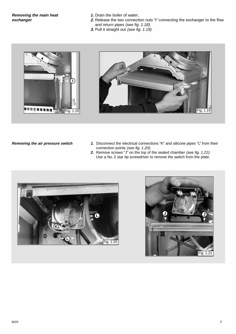
1. Disconnect the electrical connections “K” and silicone pipes “L” from theirconnection points (see fig. 1.20);
2. Remove screws “J” on the top of the sealed chamber (see fig. 1.21);Use a No. 2 star tip screwdriver to remove the switch from the plate.
Fig. 1.21
Fig. 1.20
7B029
1. Drain the boiler of water;2. Release the two connection nuts “I” connecting the exchanger to the flow
and return pipes (see fig. 1.18);3. Pull it straight out (see fig. 1.19).
Removing the main heat exchanger
Removing the air pressure switch
Fig. 1.18
I
Fig. 1.19
L
L
K
J J

8 B029
1. Disconnect the silicone pipes “M” and remove the screw “N”(see fig. 1.22);
2. Extract the venturi (see fig. 1.23).
Removing the venturi device
1. Disconnect electrical connections and remove screws “O” using a No. 2 star tipped screwdriver (see fig.1.24);
2. Pull fan to the right, forward and remove (see fig.1.25);3. Remove fan from mounting plate;4. Remove screws “P” (see fig.1.26).
Removing the fan
M N
Fig. 1.22 Fig. 1.23
Fig. 1.24
Fig. 1.25 Fig. 1.26
O
O
P
P

9B029
1.4 Servicing and Removal of the Gas Valve
1
2
3
4
A
B
C
E
F
D
SITTANDEM
SITSIGMA 1
2
3
4
A
B
C
E
F
D

10 B029
Setting the minimum and the maximum power of the boiler1. Check that the supply pressure to the gas valve is a minimum of 20 mbar
for natural gas.2. To do this, remove the screw “A” .
Fit the pipe of the pressure gauge to the pressure connection of the gasvalve “B” .When you have completed this operation, replace the screw “A” securelyinto its housing to seal off the gas.
3. To check the pressure supplied by the gas valve to the burner, remove thescrew “C” . Fit the pipe of the pressure gauge to the pressure outlet of the gas valve “D” .Disconnect the compensation pipe either from the gas valve or from the sealed chamber.
4. Set the On/Off button to position < I > and the "summer/winter" switch tothe winter position.To set the maximum power, turn on the hot water tap and allow the hotwater tap to run at a rate of about 8 litres/minute so that the main burnerlights.Adjust nut “E” on the modureg to set the gas pressure (displayed on thepressure gauge) corresponding to the maximum power (see table “A” page 11).
5. To set the minimum power, disconnect a supply terminal from the moduregand adjust screw “F” .Turn the screw clockwise to increase the pressure and coun-ter-clockwise to decrease the pressure (displayed on thepressure gauge) corresponding to the minimum power (see table “A” page11).
6. When you have completed the above operations, turn off thehot water tap, re-connect the supply terminal to the moduregon the gas valve and replace the cap on the screw of themodureg.
Setting the maximum heating circuit power7. To set the maximum heating circuit power, place the
On/Off button to position < I > and the "summer/winter" switch to winterposition.Turn the knob of the heating thermostat clockwise to maximum;
8. Remove the left hand inspection panel of the P.C.B. and fit a smallcross-head screwdriver in to the right hand potentiometer. Turn clockwiseto increase the pressure or counter-clockwise to reduce the pressure.Adjust the setting to the required heating pressure value (displayed on thepressure gauge), as indicated in the diagrams shown in page 11.
9. Turn off the boiler by placing the main switch to the "Off" position.
Setting pressure for soft ignition.Disconnect the detection electrode connection from the P.C.B. (see fig.1.13).Start the boiler and during the ignition sequence adjust the centrepotentiometer until the gas pressure reads the required gas pressure asper the table below.Once the gas pressure is set turn off the boiler and reconnect theconnection to the P.C.B.NB.: It may be necessary to reset the flame failure reset a number of timesduring this operation.
Recommended pressure for slow ignition 5 mbar - 1.95 in w.g.
NATURAL GAS (G20) BUTANE GAS (G30) PROPANE GAS (G31)
18 mbar - 7.0 in w.g. 19 mbar - 7.4 in w.g.
Setting gas pressures

11B029
model 23
model 27
Regulating the heating power fornatural gas (G20)
model 23
model 27
Regulating the heating power forbutane gas (G30)
model 23
model 27
34363840
Regulating the heating power forpropane gas (G31)
GAS REQUIREMENTS
Burner pressure
Burner injectors
min
13 x 1.25
Gas rate max 3.0 m 106.0 ft
Gas rate min 1.2 m
3/h
3/h 42.3 ft
3/h
3/h
Inlet pressure 20 mbar 7.8 in w.g.
Burner pressure max 12.3 mbar 4.8 in w.g.
2.0 mbar 0.8 in w.g.
13 x 0.72
0.88 m 31.1 ft
0.35 m
3/h
3/h 12.3 ft
3/h
3/h
28 mbar 10.9 in w.g.
28 mbar 10.9 in w.g.
5.1 mbar 2.0 in w.g.
13 x 0.72
1.15 m3/h 40.6 ft3/h
0.46 m3/h 16.2 ft3/h
37 mbar 14.4 in w .g.
37 mbar 14.4 in w .g.
7.0 mbar 2.7 in w.g.
NATURAL GAS (G20) BUTANE GAS (G30) PROPANE GAS (G31)
TABLE “A”
12 B029
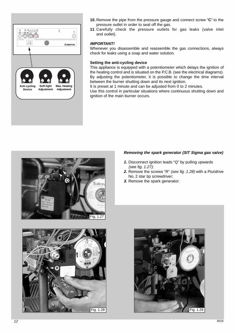
10. Remove the pipe from the pressure gauge and connect screw “C” to thepressure outlet in order to seal off the gas.
11. Carefully check the pressure outlets for gas leaks (valve inletand outlet).
IMPORTANT!Whenever you disassemble and reassemble the gas connections, alwayscheck for leaks using a soap and water solution.
Setting the anti-cycling deviceThis appliance is equipped with a potentiometer which delays the ignition ofthe heating control and is situated on the P.C.B. (see the electrical diagrams).By adjusting the potentiometer, it is possible to change the time intervalbetween the burner shutting down and its next ignition.It is preset at 1 minute and can be adjusted from 0 to 2 minutes.Use this control in particular situations where continuous shutting down andignition of the main burner occurs.
40 50 60 70 80
C C
Anti-cyclingDevice
Soft-lightAdjustment
Max. HeatingAdjustment
Removing the spark generator (SIT Sigma gas valve)
1. Disconnect ignition leads “Q” by pulling upwards (see fig. 1.27);
2. Remove the screws “R” (see fig. 1.28) with a PozidriveNo. 2 star tip screwdriver;
3. Remove the spark generator.
Fig. 1.27
Fig. 1.28 Fig. 1.29
Q
R

13B029
Removing the spark generator (SIT Tandem gasvalve)
1. Disconnect ignition leads “Q1” by pulling upwards (see fig. 1.30);
2. Remove the screws “R1” (see fig. 1.31) with a PozidriveNo. 2 star tip screwdriver;
3. Remove the spark generator.
Fig. 1.30
Fig. 1.31 Fig. 1.32
Q1
R1
R1

14 B029
1.5 Access to the Hydraulic Circuits
Fig. 1.37
UU
Removing the D.H.W. (secondary)exchanger1. Remove the screw “U” (see fig. 1.37);2. Push the exchanger towards the rear of the
boiler, lift upwards and remove out of thefront of the boiler;
3. Before replacing the exchanger ensure thatthe O-rings are in good condition andreplace if necessary.
Impor tant! Before any component is removed, the boilermust be drained of all water.
Removing the gas valve1. Disconnect all the cables from the solenoid and
modureg;2. Remove the spark generator;3. Release the top nut “S” using a 30 mm open ended
spanner (see fig. 1.31);4. Remove the screws “T” from the bottom of the gas
valve pipe (see fig. 1.32).Attention!! The gas valve is connected with the two pipes (as shown) with an O-ring connection.
Fig. 1.33 Fig. 1.34
Fig. 1.35
S
TT
Fig. 1.36

15B029
Removing the safety valve1. Loosen nut “V” (see fig. 1.38);2. Remove the valve.
Removing the automatic air vent1. Unscrew valve “W” (see fig. 1.39).
Removing the main circuit flowswitch1. Remove the cable of the main circuit flow switch “Y”;2. Remove the screws “Y1” (see fig. 1.40);3. Remove the main circuit flow switch.
Fig. 1.38
Fig. 1.39
Fig. 1.40
V
W
Y
Y1
Y1

16 B029
Removing the pump1. Unscrew “Z” and remove the electrical connection
(see fig. 1.41);2. Release the nuts “A1” and remove the pump
(see fig. 1.42).
Removing the pressure gauge1. Remove the inspection panel
(see fig. 1.6 - 1.7);2. Release coupling “A2” using a 14 mm open ended
spanner (see fig. 1.43);3. Push the pressure gauge through the control panel
from the rear (see fig. 1.44).
A1
A1
Z
A2
Fig. 1.41 Fig. 1.42
Fig. 1.43 Fig. 1.44

17B029
Removing the expansion vessel1. Remove nut “A3” away from the expansion vessel
(see fig. 1.45);2. Remove nut “A4” (see fig. 1.46);3. Remove expansion vessel (see fig. 1.47).
Removing the overheat thermostat1. Remove the electrical connection from the overheat
thermostat (see fig. 1.48);2. Then remove the thermostat from the pipe by releasing
its securing clip.
Removing the heating temperature sensor (N.T.C.)1. Remove the electrical connector by pulling off the
thermostat connections and unscrewing the sensorprobe with a 14 mm open ended spanner (see fig.1.49).
A3
A4
Fig. 1.45
Fig. 1.46
Fig. 1.48
Fig. 1.49
Fig. 1.47

18 B029
Checking fuse1. Remove the inspection panel
(see fig. 1.6 - 1.7);2. Remove fuse (see fig. 1.50).
1.6 Access to the ControlSystem
Removing the time clock1. Remove the inspection panel
(see fig. 1.6 - 1.7);2. Remove electrical connection of the clock “A5”
(see fig. 1.51);3. Unclip the clock from the panel and remove
(see fig. 1.52).
Fig. 1.50
Fig. 1.51 Fig. 1.52
A5
19B029
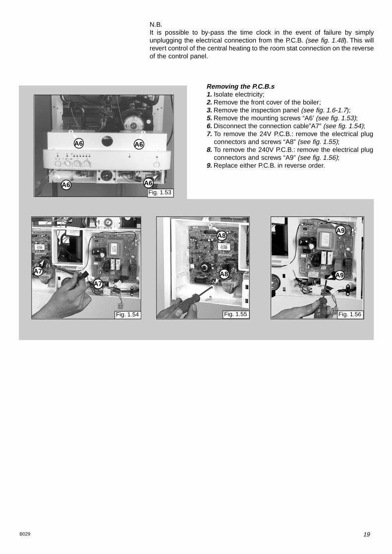
Removing the P.C.B.s1. Isolate electricity;2. Remove the front cover of the boiler;3. Remove the inspection panel (see fig. 1.6-1.7);5. Remove the mounting screws “A6’ (see fig. 1.53);6. Disconnect the connection cable”A7” (see fig. 1.54);7. To remove the 24V P.C.B.: remove the electrical plug
connectors and screws “A8” (see fig. 1.55);8. To remove the 240V P.C.B.: remove the electrical plug
connectors and screws “A9” (see fig. 1.56);9. Replace either P.C.B. in reverse order.
Fig. 1.53
Fig. 1.54 Fig. 1.55 Fig. 1.56
A6 A6
A6 A6
A7
A7 A8
A8A9
A9
N.B.It is possible to by-pass the time clock in the event of failure by simplyunplugging the electrical connection from the P.C.B. (see fig. 1.48). This willrevert control of the central heating to the room stat connection on the reverseof the control panel.

20 B029
2. FAULT FINDING
1) Thereis sufficientwater in thesystem
2) Thegas is turnedon3) Theelectricity to the
boiler is on
PreliminaryChecksMakesurethat:
HASTHE LIGHT fOR
THE POWER SUPPLYCOME ON?
SETTINGFOR THE OPERATING
MODE
IS HOTWATER BEINGDEMANDED?
NO NO
WINTERSUMMER
FUME DISCHARGE TEST
NO
YES
YES
YES
NO NO
YES
YES
1)Check the fuses2)Check thepower
supplycord,plugandoutlet
3)Check/replace thepowersupplyPCB
Press theOn / Off Button
FOR BOILERSEQUIPPEDWITHAN
ELECTRONICANT-FREEZESYSTEM:HAS THE SAFETYBEEN
TRIGGEREDTO ACTIVATETHE DEVICE?(T sensor <5°C)
FOR BOILERSEQUIPPEDWITHAN
ELECTRONICANT-FREEZESYSTEM:HAS THE SAFETYBEEN
TRIGGEREDTO ACTIVATETHE DEVICE?(T sensor <5°C)
DO THEPROGRAMMING
TIMER AND/OR EXTERNALTHERMOSTATNEEDTO BE ACTIVATED
A
IS HOTWATER BEINGDEMANDED?
It is possible to detect and correct any defect by using the standard faultfinding diagrams described in this chapter.
2.1 Fault Finding Guide(Flow-chart)

21B029
DOES THECIRCULATIONPUMP
COME ON?
YES
NO
NO
NO
YES
YES
POWERTOTHE PUMP?
DOES THEINSUFFICIENTWATER
INDICATOR LIGHTCOMEON? (within
40sec.)1)Check for air in thesystem
2)Check thepressureswitchfor activatingpump
3)Check/replacewatergaugeand refill thethesystemproperly
1)Turn theboiler offand then backonagain (safetyreset)
1)Check to see ifpump isstuck
2)Replacecirculation pump
1) Checkwiring
2) Check/replacewire to PCB
3) Replacepower supplyPCB
4) Replace controlPCB
5) Check micro-switch when hotwater is requested.
A
B

22 B029
DOES THE FANCOME ON?
BOILERSHUTDOWN?
IS THERE POWERTO THE FAN?
NO
YES
YES
YES
NO
YES
NO
NO
NO
1)Check/replacedifferentialpressureswitch for pump
2)Check/replacewiring3)Check/replacePCB wire4)Check/replacepower
supplyPCB5)Check/replacecontrol
PCB
1)pressureswitch/wiring
2)Checkwhether resetbutton isstuck
3)detection electrode
Check/replaceair
Check/replace flame
1)2)3)Check/replacepower
supplyPCB4)
5)
Check/replacewiringCheck/replacePCB wire
Check/replacecontrolPCBCheck/replaceairpressureswitch
1)Replacefan
1)Reset theboiler
PUMPSAFETYDEVICEACTIVATED?
INTERNALSAFETYDEVICE
FOR PCBACTIVATED?
B
C
YES

23B029
DOES THEBURNER LIGHT?
YES
NO
YES
YES
WAS THERESETSWITCH
PRESSED?
YES
NO
NO
NO
NO
YES
1)Check/replace igniter plugs2)Checkwiring3)Check starter4)Check small wire5)Checkpower supplyPCB6)Checkcontrol PCB
1)Checkwhether flamedetection electrodeishit by theflame
2)Check theelectrode3)Check thepower PCB4)Check thecontrol PCB
1)Check supplyofgas to gasvalve
2)Checkpower supplyPCB3)Checkcontrol PCB4)Check functionalityof the
valve
Shutdown LEDoffRestart of the fan
ISTHE AIR PRESSURE
SWITCHACTIVATED?
ARE THEFUMES DISCHARGED
CORRECTLY?
SAFETYSHUTDOWNOFTHEBOILER ACTIVATED?
1) Check flue discharge2) Check venturi & small pipes3) Check wire for air press.switch4) Check/replace air press. switch5) Check/replace PCBwire6) Check/replace powerPCB7) Check/replace control PCB
C
D

24 B029
ISTHERE STILL A
PROBLEM?
FUNCTIONSNORMALLY
NO
YES
LISTOFMALFUNCTIONS POSSIBLE CAUSES1
2
3
4
5
6
7
8
9
Deliveryofhot water for domestic use:when the tap is turnedon, theburner goesout.
Deliveryofhot water for domestic use:theradiatoresareheated in summer mode.
Deliveryofhot water for domestic use:water temperature isnot satisfactory.
Deliveryofhot water for domestic use:noisyoperation.
Drop/increase in pressure in primarycircuit.
Repeated shutdowns.
Safety thermostat is triggered repeatedly.
When thecoldwater tap is turnedoff, theboiler comeson.
Temperatureof radiatorsnot satisfactory.
- Air in thesecondaryexchanger- Hot water pressureswitch isdefective- 3-wayvalve isdefective
- 3-wayvalve isdefective
- Checkheating sensors- Checkgassettingsand regulation- Checkwater flow rate- Checkexchanger for domestic hot water
- Primaryexchanger isdefective- Low water pressure in heating system- Checkgassettingsand regulation
- Check for leaks in heating circuit- Defectivewater supply inlet valve- Secondaryexchanger isdefective- Expansion vessal isempty
- Detection electrodesaredefective- Checkgassettingsand regulation- Checkelectrical circuit for flamedetection
- Faulty (contacts)ntc heating sensors-- Defective (poorlycalibrated)safety thermostat- Presenceofair in theprimarywater circuit
- Drop in pressure in thewater mains, resultingin water hammering
- Checkntc heating sensor- Checkby-pass- Checkgassettingsand regulation
D
25B029
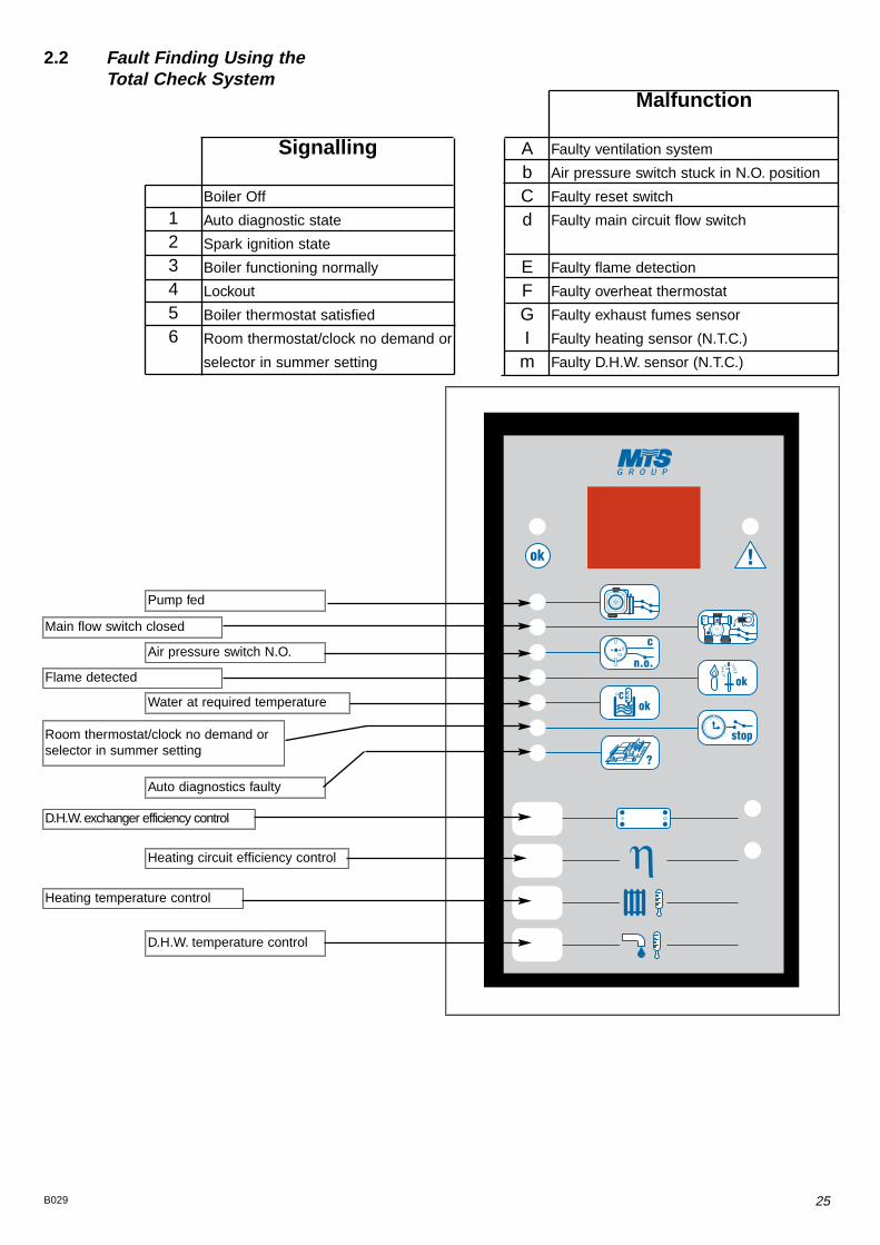
Signalling
Boiler Off
Auto diagnostic state
Spark ignition state
Boiler functioning normally
Lockout
Boiler thermostat satisfied
Room thermostat/clock no demand or
selector in summer setting
Malfunction
Faulty ventilation system
Air pressure switch stuck in N.O. position
Faulty reset switch
Faulty main circuit flow switch
Faulty flame detection
Faulty overheat thermostat
Faulty exhaust fumes sensor
Faulty heating sensor (N.T.C.)
Faulty D.H.W. sensor (N.T.C.)
AbCd
EFGIm
123456
2.2 Fault Finding Using the Total Check System
Pump fed
Main flow switch closed
Air pressure switch N.O.
Flame detected
Water at required temperature
Room thermostat/clock no demand orselector in summer setting
Auto diagnostics faulty
Heating temperature control
D.H.W. temperature control
Heating circuit efficiency control
D.H.W.exchanger efficiency control

26 B029
3. ELECTRICAL
DIAGRAMS
Legend:
AT = High Voltage P.C.B.BT = Low Voltage P.C.B.B = Flame Failure L.E.D.C = Insufficient Water Pressure L.E.D.D = Water Temperature Indicator L.E.D.sE = Overheat Thermostat Warning L.E.D.F = System Reset ButtonG = Selector Knob for Operating ModeH = Domestic Hot Water Temp. AdjustmentI = Central Heating Temp. AdjustmentJ = Wire Connector for Room ThermostatK = Connector for Total Check SystemM = Anti-cycling Device Adjustment for HeatingN = Soft-light AdjustmentO = Max Heating Temperature AdjustmentP = Time Clock Connection Q = On/Off L.E.D.R = On/Off SwitchS = Interface Wire for P.C.B.sT = Relay Motorised ValveU = Ignitor RelayV = Gas Valve RelayW = Fan RelayX = Circulation Pump RelayY = Selector TCS2Aa = Adaptor (British Gas use only)
A01 = Air Pressure SwitchA02 = FanA03 = Gas ValveA04 = IgnitorA05 = Motorised ValveA06 = Circulation PumpA07 = Flame DetectorA08 = Earth TerminalA09 = Flame Detection CircuitA10 = Flame Indicator L.E.D.A11 = TransformerA12 = Filter
B01 = Over Heat ThermostatB02 = Room ThermostatB03 = Gas Valve ModulatorB05 = Heating SensorB06 = Pressure Switch for Heating CircuitB07 = Microswitch for Diverter ValveB08 = Time Clock
Colours
Gry = GreyRd = RedBl = BlueGrn/Yll = Yellow/Green Wh = WhiteBrn = BrownBlk = BlackWh/Rd = White/Red

27B029
EX
C-M
I/FF
I
8
A/23 MFFI - A/27 MFFI

28 B029
90
56
55
68 60 572
11
9
1
2
3
6
7
8
12
13
11
16 17 18 19 2320 21 22 24 2625
88 87
8686
8987
85
84
98
85
11
120
7
81
63
82
124
122
118119
112
111
4
4 4
4
90
15
67 59 5861
125
123
107
109
82
66 64676669706471
75
75
6365
75
126
72
121
74
10
62
73
80
28
46
45
45
116
54114
495051
115
113
48
4952
52
53
4745
343332 3529 30
103
27
117
5
96
102
100
101
100
41
39
97
108
14
37
39
34
38
2941
40
4344
42
301 4 302 301
4
44
93 9292
91
94
9523
83106
105
79
3631
76
7778
99
104
110
321
361
363
364
362
371
372373
374
375
311
A 23/27 MFFI
102 16
2217
4. SHORT SPARE
PARTS LIST
A/23 MFFI - A/27 MFFI (SIT Sigma Gas Valve)

29B029
573294573520997206573224569236573340573528573727573172571649997208953730952981952610572989572990573343573314571651571652570717564254569387571449571646573295573825571807573521997150997151571965574279574232574233573441569390569560569561572271572277572343572372572749572835571993571444997029571443571442571447571446571547571772571771571770573138569281569282
Keyno.
G.C. partno.
ARISTONPart No.Description
111141718192324252832454647
57AB57CD
5861
72AB72CD
75848587
89AB89CD
909296
98AB98CD100101102108112116118119
120A120B120C120D
121AB121CD
301311321361362363364371372373374375381382
379816164 225
164 338
164 229378 814
E03 818E02 071
379 079164 230
164 282
379 981164 261379 979379 980E02 026
E02 078
164 311
Expansion vesselGasket 3/4"Overheat thermostatMain flow SwitchTemp probe (C.H.W.)Microswitch for 3-way/main flow groupGasket 1/2"Manual vent cockSafety valve 3 bar 1/2"Pressure gaugeTime clockP.C.B. EX C-MI/FFIP.C.B. EI A-MFFIP.C.B. cableFanFanFan inlet gasketVenturi (exhaust manifold/header)Air pressure switchAir pressure switchFastening springAutomatic air release valveGasket 1"O-ringSecondary exchanger (plate-type) exchanger 23kWSecondary exchanger (plate-type) exchanger 27kWO-ring (secondary exchanger)20-18 O-ringGasket 3/8"PumpPumpO-ring (13)GasketGas valve (SIT Sigma)Spark generatorDetection electrodeGasket 1/4"Ignition electrode (R.H.)Ignition electrode (L.H.)Main burnerMain burnerMain burnerMain burnerMain exchangerMain exchangerFront panel runner kitD.H.W. actuator kitSIT Sigma gas valve operator coilsHeating by-pass kitD.H.W. pressure switch kit3-way spring kitD.H.W. diaphram valveMain flow switch diaphramMain flow switch magnetMain flow switch springMain flow switch top capMain flow switch reed systemBurner jet 1.25 full kit (Natural gas)Burner jet 0.72 full kit (LPG)
1
1111
1111111111111
11
1
1111
111111111111
A/23 MFFI - A/27 MFFI (SIT Sigma Gas Valve)

30 B029
573294573520997206573224569236573340573528573727573172571649997207953730952981952610572989572990573343573314571651571652570717564254569387571449571646573295573825571807573521997150997151570732573023571965573441569390569560569561572271572277572343572372572749572835571444570712573740573745571443571442571447571446571547571772571771571770573138569281569282
Keyno.
G.C. partno.
ARISTONPart No.Description
111141718192324252831444647
57AB57CD
5861
72AB72CD
75848587
89AB89CD
909296
98AB98CD101
106114118120121
122A122B122C122D
123AB123CD
311321322323361362363364371372373374375381382
379816164 225 164 338 164 229378 814
E03 818E02 071
379 079164 230
164 282
379 976
379 981164 261379 979379 980E02 026
E02 078
378 978378 815164 303
164 311
Expansion vesselGasket 3/4"Overheat thermostatMain flow SwitchTemp probe (C.H.W.)Microswitch for 3-way/main flow groupGasket 1/2"Manual vent cockSafety valve 3 bar 1/2"Pressure gaugeTime clockP.C.B. EX C-MI/FFIP.C.B. EI A-MFFIP.C.B. cableFanFanFan inlet gasketVenturi (exhaust manifold/header)Air pressure switchAir pressure switchFastening springAutomatic air release valveGasket 1"O-ringSecondary exchanger (plate-type) exchanger 23kWSecondary exchanger (plate-type) exchanger 27kWO-ring (secondary exchanger)O-ring (20-18)Gasket 3/8"PumpPumpGas valve (SIT Tandem)Spark generatorO-ring (13)Detection electrodeGasket 1/4"Ignition electrode (R.H.)Ignition electrode (L.H.)Main burnerMain burnerMain burnerMain burnerMain exchangerMain exchangerD.H.W. actuator kitSIT Tandem gas valve operator coilsSIT Tandem modureg coilGas modulator cartridgeHeating by-pass kitD.H.W. pressure switch kit3-way spring kitD.H.W. diaphram valveMain flow switch diaphramMain flow switch magnetMain flow switch springMain flow switch top capMain flow switch reed systemBurner jet 1.25 full kit (Natural gas)Burner jet 0.72 full kit (LPG)
1
1111
1111111111111
11
1
1111
111111111111
103
A/23 MFFI - A/27 MFFI (SIT Tandem Gas Valve)

31B029
573294573520997206573224569236573340573528573727573172571649997207953730952981952610572989572990573343573314571651571652570717564254569387571449571646573295573825571807573521997150997151570732573023571965573441569390569560569561572271572277572343572372572749572835571444570712573740573745571443571442571447571446571547571772571771571770573138569281569282
Keyno.
G.C. partno.
ARISTONPart No.Description
111141718192324252831444647
57AB57CD
5861
72AB72CD
75848587
89AB89CD
909296
98AB98CD101
106114118120121
122A122B122C122D
123AB123CD
311321322323361362363364371372373374375381382
379816164 225 164 338 164 229378 814
E03 818E02 071
379 079164 230
164 282
379 976
379 981164 261379 979379 980E02 026
E02 078
378 978378 815164 303
164 311
Expansion vesselGasket 3/4"Overheat thermostatMain flow SwitchTemp probe (C.H.W.)Microswitch for 3-way/main flow groupGasket 1/2"Manual vent cockSafety valve 3 bar 1/2"Pressure gaugeTime clockP.C.B. EX C-MI/FFIP.C.B. EI A-MFFIP.C.B. cableFanFanFan inlet gasketVenturi (exhaust manifold/header)Air pressure switchAir pressure switchFastening springAutomatic air release valveGasket 1"O-ringSecondary exchanger (plate-type) exchanger 23kWSecondary exchanger (plate-type) exchanger 27kWO-ring (secondary exchanger)O-ring (20-18)Gasket 3/8"PumpPumpGas valve (SIT Tandem)Spark generatorO-ring (13)Detection electrodeGasket 1/4"Ignition electrode (R.H.)Ignition electrode (L.H.)Main burnerMain burnerMain burnerMain burnerMain exchangerMain exchangerD.H.W. actuator kitSIT Tandem gas valve operator coilsSIT Tandem modureg coilGas modulator cartridgeHeating by-pass kitD.H.W. pressure switch kit3-way spring kitD.H.W. diaphram valveMain flow switch diaphramMain flow switch magnetMain flow switch springMain flow switch top capMain flow switch reed systemBurner jet 1.25 full kit (Natural gas)Burner jet 0.72 full kit (LPG)
1
1111
1111111111111
11
1
1111
111111111111
103
A 23/27 MFFI (SIT Tandem Gas Valve)

Manufacturer: Merloni TermoSanitari SpA - Italy
Commercial subsidiary: MTS (GB) LIMITEDMTS BuildingHughenden Avenue,High WycombeBucks HP13 5FTTelephone: (01494) 755600 -Fax: (01494) 459775Technical Service Hotline: (01494) 539579
23 9
9 84
126
8 00
0-
B02
9
S
tam
pa B
IEF
FE
Rec
anat
i