Embed Size (px)
Citation preview

This document applies to ARIS Version 10.0 and to all subsequent releases. Specifications contained herein are subject to change and these changes will be reported in subsequent release notes or new editions. Copyright © 2010 - 2017 Software AG, Darmstadt, Germany and/or Software AG USA Inc., Reston, VA, USA, and/or its subsidiaries and/or its affiliates and/or their licensors. The name Software AG and all Software AG product names are either trademarks or registered trademarks of Software AG and/or Software AG USA Inc. and/or its subsidiaries and/or its affiliates and/or their licensors. Other company and product names mentioned herein may be trademarks of their respective owners. Detailed information on trademarks and patents owned by Software AG and/or its subsidiaries is located at http://softwareag.com/licenses (http://softwareag.com/licenses). Use of this software is subject to adherence to Software AG's licensing conditions and terms. These terms are part of the product documentation, located at http://softwareag.com/licenses (http://softwareag.com/licenses) and/or in the root installation directory of the licensed product(s). This software may include portions of third-party products. For third-party copyright notices, license terms, additional rights or restrictions, please refer to "License Texts, Copyright Notices and Disclaimers of Third Party Products". For certain specific third-party license restrictions, please refer to section E of the Legal Notices available under "License Terms and Conditions for Use of Software AG Products / Copyright and Trademark Notices of Software AG Products". These documents are part of the product documentation, located at http://softwareag.com/licenses (http://softwareag.com/licenses) and/or in the root installation directory of the licensed product(s).

DESIGNER USER MANUAL
I
Contents 1 ARIS Connect ....................................................................................................... 1
2 Basics .................................................................................................................. 2 2.1 Text conventions ......................................................................................... 2 2.2 Help content shown ..................................................................................... 2 2.3 Select language ........................................................................................... 3 2.4 Edit your user account ................................................................................. 3 2.5 Change password ........................................................................................ 4 2.6 Switch your profile ....................................................................................... 4 2.7 Start search ................................................................................................ 4 2.8 Show tasks in ARIS Process Board ................................................................. 5 2.9 Open ARIS Download Client page .................................................................. 5 2.10 Open Help .................................................................................................. 5 2.11 Forward a page of the online help .................................................................. 6 2.12 Open Administration .................................................................................... 6 2.13 Play videos ................................................................................................. 7 2.14 Open information window ............................................................................. 7 2.15 Known issues .............................................................................................. 7 2.16 Log out of ARIS Connect ............................................................................... 8 2.17 What profiles include which content? .............................................................. 9
3 Use ARIS Connect ............................................................................................... 10 3.1 Work in the portal ...................................................................................... 10
3.1.1 Views ............................................................................................ 10 3.1.1.1 Classic view............................................................................... 11
3.1.1.1.1 Home ..................................................................................... 13 3.1.1.1.2 Groups ................................................................................... 14 3.1.1.1.3 Glossary ................................................................................. 26
3.1.1.2 Default view .............................................................................. 29 3.1.1.2.1 Processes ............................................................................... 30 3.1.1.2.2 Organization ........................................................................... 41 3.1.1.2.3 IT systems .............................................................................. 42 3.1.1.2.4 Glossary ................................................................................. 45
3.1.2 Use the portal ................................................................................. 48 3.1.2.1 Select database ......................................................................... 48 3.1.2.2 Navigate ................................................................................... 49 3.1.2.3 Navigate step by step ................................................................. 50 3.1.2.4 Choose glossary items starting with the same letter ....................... 50 3.1.2.5 Filter glossary items based on name, description, and responsibility
............................................................................................... 51 3.1.2.6 Remove glossary filter ................................................................ 51 3.1.2.7 Change the glossary page ........................................................... 52 3.1.2.8 Switch from Steps to Diagram ..................................................... 52 3.1.2.9 Print the graphic of the current model .......................................... 53 3.1.2.10 Display the current method filter .................................................. 53 3.1.2.11 Generate report ......................................................................... 54 3.1.2.12 Use the Favorites tab in the portal ............................................... 56 3.1.2.13 Show where object occurrences are used ...................................... 57 3.1.2.14 Submit change request ............................................................... 57 3.1.2.15 Comment on portal content ......................................................... 58 3.1.2.16 Start governance process ............................................................ 59 3.1.2.17 Follow processes in the portal ...................................................... 59 3.1.2.18 Request feedback on processes ................................................... 60

DESIGNER USER MANUAL
II
3.1.3 Use roles ........................................................................................ 61 3.1.3.1 Assign roles ............................................................................... 61 3.1.3.2 Activate role filter ...................................................................... 62
3.1.4 Use models .................................................................................... 63 3.1.4.1 Open assignment ....................................................................... 63 3.1.4.2 Open placed link attributes .......................................................... 63 3.1.4.3 Switch from Steps to Diagram ..................................................... 64 3.1.4.4 Print the graphic of the current model .......................................... 64 3.1.4.5 Ask for model approval ............................................................... 65 3.1.4.6 Share model .............................................................................. 66 3.1.4.7 Inform owner of change .............................................................. 67 3.1.4.8 Generate report ......................................................................... 68 3.1.4.9 Create model ............................................................................. 69 3.1.4.10 Edit models ............................................................................... 70 3.1.4.11 Use matrix models ..................................................................... 71
3.1.4.11.1 Open a matrix model in ARIS Connect ........................................ 71 3.1.4.11.2 Display use of connections for a matrix model in ARIS Connect ..... 71 3.1.4.11.3 Show/Hide hierarchies in a matrix model in ARIS Connect ............ 72 3.1.4.11.4 How are connections displayed? ................................................ 72
3.1.5 Handle documents .......................................................................... 73 3.1.5.1 Propose document ..................................................................... 73 3.1.5.2 Link new documents to a model or object ..................................... 74 3.1.5.3 Add existing documents to a model or object ................................. 75 3.1.5.4 Submit a change request for a document ...................................... 76 3.1.5.5 Have document approved ........................................................... 78 3.1.5.6 Share document ........................................................................ 79 3.1.5.7 Find a document ........................................................................ 81 3.1.5.8 Rename document ..................................................................... 81 3.1.5.9 Show links of a document ........................................................... 82 3.1.5.10 Remove document from a model or object .................................... 82 3.1.5.11 Show version of a document........................................................ 83 3.1.5.12 Handle document versions .......................................................... 84
3.1.5.12.1 Show version of a document ..................................................... 84 3.1.5.12.2 Show version history ................................................................ 84 3.1.5.12.3 Delete version of a document .................................................... 85
3.1.5.13 Handle document with Document administrator privilege ................ 86 3.1.5.13.1 Add documents to ARIS document storage ................................. 86 3.1.5.13.2 Open/Download document ........................................................ 86 3.1.5.13.3 Select document manager ........................................................ 87 3.1.5.13.4 Upload multiple documents ....................................................... 87 3.1.5.13.5 Upload version of a document ................................................... 88 3.1.5.13.6 Sort versions of a document ..................................................... 88 3.1.5.13.7 Download multiple documents ................................................... 89 3.1.5.13.8 Move document ....................................................................... 89 3.1.5.13.9 Move multiple documents ......................................................... 89 3.1.5.13.10 Browse ARIS document storage ......................................... 90 3.1.5.13.11 Lock document ................................................................ 90 3.1.5.13.12 Unlock document ............................................................. 91 3.1.5.13.13 Delete document from ARIS document storage .................... 91 3.1.5.13.14 Delete multiple documents from ARIS document storage ...... 92 3.1.5.13.15 Delete documents from the repository ................................ 92

DESIGNER USER MANUAL
III
3.1.6 Search content ............................................................................... 93 3.1.6.1 Start quick search ...................................................................... 93 3.1.6.2 Open Search area with term to be searched for ............................. 94 3.1.6.3 Open Search area directly ........................................................... 94 3.1.6.4 Find using the Search area .......................................................... 95 3.1.6.5 Use search context and filters ...................................................... 96 3.1.6.6 Save filter settings as a favorite ................................................... 97 3.1.6.7 Use a favorite in the Search area ................................................. 97 3.1.6.8 Use a favorite in the Favorites area .............................................. 98 3.1.6.9 Clear filters ............................................................................... 99 3.1.6.10 Open search result on separate tab ............................................. 100 3.1.6.11 Valuable information ................................................................. 101
3.1.6.11.1 How is the quick search structured? .......................................... 101 3.1.6.11.2 How is the Search area structured? ........................................... 102 3.1.6.11.3 How is the Favorites area structured? ....................................... 103 3.1.6.11.4 How can search results be influenced? ...................................... 103
3.1.7 Contribute as a viewer .................................................................... 104 3.1.7.1 Change values of items .............................................................. 104 3.1.7.2 Create or reuse items in a table .................................................. 105 3.1.7.3 Create or reuse items in a list ..................................................... 106 3.1.7.4 Delete items from tables ............................................................ 107 3.1.7.5 Delete items from lists ............................................................... 108 3.1.7.6 Valuable information ................................................................. 109
3.1.7.6.1 Requirements for Contribution ................................................. 109 3.1.7.6.2 How to identify whether the edit mode is active ......................... 109 3.1.7.6.3 Which items are you allowed to change using the Contribution
privilege? .............................................................................. 110 3.1.7.6.4 Which attributes are you able to edit? ....................................... 111 3.1.7.6.5 Which editing options are available? ......................................... 112 3.1.7.6.6 Where to save new items ........................................................ 115
3.1.8 Manage SAP Solutions .................................................................... 116 3.1.8.1 Run SAP® transaction ............................................................... 116 3.1.8.2 Reset SAP® logon data .............................................................. 117 3.1.8.3 Download SAP® documents ....................................................... 117 3.1.8.4 Configure ARIS Online Guide ...................................................... 118 3.1.8.5 Start ARIS Online Guide ............................................................. 119
3.1.9 Use RACI matrix ............................................................................ 120 3.1.9.1 Create process model for RACI matrix ......................................... 120 3.1.9.2 Display RACI matrix .................................................................. 121 3.1.9.3 Valuable information ................................................................. 122
3.1.9.3.1 Which diagrams can be used for a RACI matrix? ......................... 122 3.1.9.3.2 Which objects can be used for a RACI matrix? ............................ 122 3.1.9.3.3 Which connections can be used for a RACI matrix? ..................... 123
3.1.10 Use Mini workflows ......................................................................... 124 3.1.10.1 Edit models .............................................................................. 124 3.1.10.2 Share model ............................................................................. 124 3.1.10.3 Submit change request .............................................................. 125 3.1.10.4 Ask for model approval .............................................................. 126 3.1.10.5 Request feedback on processes .................................................. 127 3.1.10.6 Inform owner of change ............................................................. 128
3.1.11 Use dashboards ............................................................................. 129 3.1.11.1 Open a dashboard in ARIS Connect ............................................. 129 3.1.11.2 Create a dashboard in ARIS Connect ........................................... 129 3.1.11.3 Open a data feed in ARIS Connect ............................................... 130
DESIGNER USER MANUAL
IV
3.1.11.4 Create a data feed in ARIS Connect ............................................. 131 3.1.11.5 Show dashboards ...................................................................... 132
3.1.12 Valuable information ...................................................................... 133 3.1.12.1 In which order are object occurrences displayed? .......................... 133 3.1.12.2 What is the portal view? ............................................................ 133 3.1.12.3 What is the structure of the classic view? ..................................... 134 3.1.12.4 What is the structure of the default view? .................................... 136 3.1.12.5 When can UML content be displayed? .......................................... 137 3.1.12.6 Where is UML content displayed? ................................................ 137 3.1.12.7 What is the context for executable processes? .............................. 137 3.1.12.8 What are role filters? ................................................................. 138 3.1.12.9 What is ARIS Viewer Contribution? .............................................. 139 3.1.12.10 What is the breadcrumb navigation? ............................................ 141 3.1.12.11 What reports are available? ........................................................ 141
3.1.12.11.1 Create process manual .................................................... 142 3.1.12.11.2 Export graphic as PDF ...................................................... 143 3.1.12.11.3 Generate job description .................................................. 144 3.1.12.11.4 Output functions across multiple assignment levels ............. 146 3.1.12.11.5 Output functions with connected objects ............................ 148 3.1.12.11.6 Output model information ................................................ 149 3.1.12.11.7 Output model information considering various aspects ......... 150 3.1.12.11.8 Output object information ................................................ 151 3.1.12.11.9 Process manual (example) ............................................... 151 3.1.12.11.10 RA(S)CI - Output organizational participations in processes
.................................................................................... 152 3.1.12.12 What report output formats exist? ............................................... 154 3.1.12.13 What is ARIS Aware (Dashboards)? ............................................. 154 3.1.12.14 What are the ARIS Aware fields? ................................................. 155 3.1.12.15 What is an alias of a URL? .......................................................... 156 3.1.12.16 What dashboards are available by default? ................................... 156
3.1.12.16.1 Based on Center of Excellence (CoE) ................................. 156 3.1.12.16.1.1 CoE - Aggregated Maturity Overview ................................. 156 3.1.12.16.1.2 CoE - Aggregated Maturity Diagram .................................. 158 3.1.12.16.1.3 CoE - Local Maturity # Dashboard ..................................... 159 3.1.12.16.1.4 CoE - Global Maturity ....................................................... 160 3.1.12.16.1.5 CoE - Process Change Management ................................... 162 3.1.12.16.1.6 CoE - Human Task .......................................................... 164
3.1.12.16.2 Based on Customer Experience (CXM) ............................... 166 3.1.12.16.2.1 Customer experience ....................................................... 166 3.1.12.16.2.2 Responsibilities ............................................................... 170 3.1.12.16.2.3 Customer journey map .................................................... 173
3.1.12.16.3 Based on Piwik................................................................ 176 3.1.12.16.3.1 Piwik - Publications .......................................................... 176 3.1.12.16.3.2 Piwik - Technical KPIs ...................................................... 178
3.1.12.16.4 Based on EA ................................................................... 180 3.1.12.16.4.1 EA dashboard for organizational units ................................ 180 3.1.12.16.4.2 EA dashboard for IT systems ............................................ 184 3.1.12.16.4.3 EA dashboard for objectives ............................................. 187
3.2 Collaborate with users ............................................................................... 189 3.2.1 Getting started .............................................................................. 189 3.2.2 Open Collaboration ......................................................................... 189 3.2.3 Create or edit a user profile ............................................................. 189 3.2.4 Find users and groups and follow their feeds ..................................... 190 3.2.5 Follow and comment on content in the portal as a user ....................... 191
DESIGNER USER MANUAL
V
3.2.6 Publish posts ................................................................................. 192 3.2.7 Comment on, share, flag posts, etc. ................................................. 193 3.2.8 Add documents to posts .................................................................. 194 3.2.9 View notifications and specify settings .............................................. 194 3.2.10 Define filters .................................................................................. 195 3.2.11 Use tags ....................................................................................... 195 3.2.12 Filter feeds by means of tags ........................................................... 196 3.2.13 Use hashtags ................................................................................. 196 3.2.14 Find help ....................................................................................... 196 3.2.15 Work with groups ........................................................................... 197
3.2.15.1 Create, edit or delete a group ..................................................... 197 3.2.15.2 Invite other users to join a group ................................................ 198 3.2.15.3 Follow portal contents as a group ................................................ 198
3.2.16 Edit requests to join private groups as a coordinator .......................... 199 3.2.17 Grant/revoke group users coordinator privileges ................................ 199 3.2.18 Valuable information ...................................................................... 200
3.2.18.1 What is a feed? ......................................................................... 200 3.2.18.2 Which target groups can be assigned to posts? ............................. 200 3.2.18.3 What does following posts mean?................................................ 201 3.2.18.4 What does Like mean? ............................................................... 201 3.2.18.5 What is a timestamp? ................................................................ 201 3.2.18.6 What is a tag? .......................................................................... 201 3.2.18.7 What is a hashtag? .................................................................... 201 3.2.18.8 What does flagging a post mean? ................................................ 202 3.2.18.9 Which group types exist? ........................................................... 202 3.2.18.10 Which access rights of ARIS Architect are relevant to Collaboration?
.............................................................................................. 202 3.3 Use the repository .................................................................................... 203
3.3.1 Create and edit models ................................................................... 203 3.3.1.1 Create/Import a model .............................................................. 203
3.3.1.1.1 Create new model .................................................................. 203 3.3.1.1.2 Create a new model using an assignment .................................. 204 3.3.1.1.3 Create group .......................................................................... 205 3.3.1.1.4 Import ARIS Express model ..................................................... 205 3.3.1.1.5 Import BPMN file .................................................................... 206
3.3.1.2 Customize Model Editor ............................................................. 206 3.3.1.2.1 Show and hide bars ................................................................ 206 3.3.1.2.2 Show/Hide header .................................................................. 207 3.3.1.2.3 Customize Symbols bar ........................................................... 207 3.3.1.2.4 Customize Attributes tab ......................................................... 208 3.3.1.2.5 Show and hide mini toolbar ..................................................... 209 3.3.1.2.6 Configure mini toolbar ............................................................. 209 3.3.1.2.7 Change grid width .................................................................. 210 3.3.1.2.8 Show formatting toolbar .......................................................... 210 3.3.1.2.9 Assign model template ............................................................ 210 3.3.1.2.10 Reset model template ............................................................. 211
3.3.1.3 Model ...................................................................................... 212 3.3.1.3.1 Open model for editing ............................................................ 212 3.3.1.3.2 Change database language of a model ...................................... 213 3.3.1.3.3 Show and hide grid ................................................................. 213 3.3.1.3.4 Set grid width ........................................................................ 214 3.3.1.3.5 Place object symbols ............................................................... 214 3.3.1.3.6 Place occurrence copy ............................................................. 216 3.3.1.3.7 Paste copied object as an occurrence copy ................................. 217

DESIGNER USER MANUAL
VI
3.3.1.3.8 Paste copied object as a definition copy ..................................... 217 3.3.1.3.9 Change object symbol ............................................................. 218 3.3.1.3.10 Place graphic objects .............................................................. 218 3.3.1.3.11 Paste copied graphic objects .................................................... 220 3.3.1.3.12 Modeling using the mini toolbar ................................................ 220 3.3.1.3.13 Edit attributes ........................................................................ 221 3.3.1.3.14 Directly format placed attributes .............................................. 221 3.3.1.3.15 Create connections ................................................................. 222 3.3.1.3.16 Place text .............................................................................. 223 3.3.1.3.17 Adjust size of appearance ........................................................ 223 3.3.1.3.18 Delete model items ................................................................. 223 3.3.1.3.19 Save model ........................................................................... 224 3.3.1.3.20 Change BPMN object symbol .................................................... 224 3.3.1.3.21 Change loop type ................................................................... 224 3.3.1.3.22 Add lane ................................................................................ 225 3.3.1.3.23 Insert lane into a pool or lane .................................................. 225 3.3.1.3.24 Move lane .............................................................................. 225 3.3.1.3.25 Delete pool or lane ................................................................. 226 3.3.1.3.26 Transform communication into call conversation ......................... 226 3.3.1.3.27 Change type of sequence flow .................................................. 226 3.3.1.3.28 Collapse subprocess ................................................................ 227 3.3.1.3.29 Expand subprocess ................................................................. 227 3.3.1.3.30 Edit subprocess ...................................................................... 227 3.3.1.3.31 Assign global reference to call activity ....................................... 228 3.3.1.3.32 Model table-based .................................................................. 228
3.3.1.3.32.1 Hide/Show modeling table ................................................ 228 3.3.1.3.32.2 Switch full-screen mode on/off ......................................... 229 3.3.1.3.32.3 Show/Hide BPMN container .............................................. 229 3.3.1.3.32.4 Create object .................................................................. 229 3.3.1.3.32.5 Create object with special object symbol ............................ 230 3.3.1.3.32.6 Use existing object .......................................................... 230 3.3.1.3.32.7 Rename structurally relevant object .................................. 230 3.3.1.3.32.8 Edit the Description/Definition column ............................... 231 3.3.1.3.32.9 Create split paths ............................................................ 231 3.3.1.3.32.10 Remove object from model ............................................... 232 3.3.1.3.32.11 Model satellites ............................................................... 232 3.3.1.3.32.12 Add object column .......................................................... 233 3.3.1.3.32.13 Add attribute column ....................................................... 233 3.3.1.3.32.14 Edit attribute .................................................................. 234 3.3.1.3.32.15 Arrange columns ............................................................. 234 3.3.1.3.32.16 Remove column .............................................................. 235 3.3.1.3.32.17 Valuable information........................................................ 236
3.3.1.3.32.17.1 What models can be edited using a table? .................. 236 3.3.1.3.32.17.2 How to control the table using the keyboard ............... 236 3.3.1.3.32.17.3 What do different colors mean in table-based
modeling? .............................................................. 237 3.3.1.3.32.17.4 What default columns are available? .......................... 239 3.3.1.3.32.17.5 What are the special features of BPMN diagrams? ....... 240 3.3.1.3.32.17.6 What attribute values and processing types are there?
........................................................................ 241 3.3.1.4 Extended editing ....................................................................... 244
3.3.1.4.1 Find objects in an open model .................................................. 244 3.3.1.4.2 Show where object occurrences are used .................................. 245 3.3.1.4.3 Place an object in an object ..................................................... 245 3.3.1.4.4 Place an object on an object .................................................... 246 3.3.1.4.5 Upload documents .................................................................. 246

DESIGNER USER MANUAL
VII
3.3.1.4.6 Assign documents ................................................................... 247 3.3.1.4.7 Link documents ...................................................................... 248 3.3.1.4.8 Use the Documentation attribute .............................................. 249 3.3.1.4.9 Format painter ....................................................................... 251 3.3.1.4.10 Color model items .................................................................. 251 3.3.1.4.11 Color model items with a user-defined color ............................... 252 3.3.1.4.12 Color model items with a gradient ............................................ 252 3.3.1.4.13 Display model items without color ............................................ 253 3.3.1.4.14 Reset object symbol color ........................................................ 253 3.3.1.4.15 Color borders and lines ........................................................... 253 3.3.1.4.16 Reset border and line color ...................................................... 254 3.3.1.4.17 Change line style .................................................................... 254 3.3.1.4.18 Change line weight ................................................................. 254 3.3.1.4.19 Change item appearance ......................................................... 255 3.3.1.4.20 Place attributes at fixed positions ............................................. 255 3.3.1.4.21 Place attributes at any position ................................................ 256 3.3.1.4.22 Place attributes from Attributes tab .......................................... 257 3.3.1.4.23 Display names of placed attributes ........................................... 257 3.3.1.4.24 Select placed attributes ........................................................... 257 3.3.1.4.25 Edit placed attributes .............................................................. 258 3.3.1.4.26 Directly format placed attributes .............................................. 258 3.3.1.4.27 Move placed attribute.............................................................. 258 3.3.1.4.28 Display placed attributes as a symbol ........................................ 259 3.3.1.4.29 Remove placed attribute .......................................................... 259 3.3.1.4.30 Remove multiple placed attributes ............................................ 259 3.3.1.4.31 Assign a model to an object ..................................................... 260 3.3.1.4.32 Place model items one behind the other .................................... 260 3.3.1.4.33 Group model items ................................................................. 261 3.3.1.4.34 Ungroup ................................................................................ 261 3.3.1.4.35 Align model items ................................................................... 261 3.3.1.4.36 Match size of items ................................................................. 262 3.3.1.4.37 Select object or model in Explorer ............................................ 262 3.3.1.4.38 Map Alfabet objects to ARIS objects .......................................... 262
3.3.2 Create Alfabet object ...................................................................... 263 3.3.2.1.1 Unmap Alfabet object .............................................................. 263
3.3.2.2 Valuable information ................................................................. 264 3.3.2.2.1 How is the Model Editor structured? .......................................... 264 3.3.2.2.2 What model types are available in ARIS Connect? ....................... 269 3.3.2.2.3 Which method filter is used? .................................................... 272 3.3.2.2.4 What are tab bars for? ............................................................ 273 3.3.2.2.5 What general buttons are available? ......................................... 274 3.3.2.2.6 What buttons does the Start tab bar have? ................................ 275 3.3.2.2.7 What buttons does the Model tab bar have? ............................... 276 3.3.2.2.8 What buttons does the Format tab bar have? ............................. 277 3.3.2.2.9 What buttons does the BPMN tab bar have? ............................... 278 3.3.2.2.10 What is the mini toolbar for? .................................................... 279 3.3.2.2.11 How are object relationships displayed by symbols? .................... 279 3.3.2.2.12 What placed attribute does an object have? ............................... 279 3.3.2.2.13 What to consider when placing objects in/on objects ................... 280 3.3.2.2.14 What does place attribute as a symbol mean? ............................ 280 3.3.2.2.15 What does place attribute as a symbol mean? ............................ 281 3.3.2.2.16 What happens to placed attributes that have no attribute value? .. 281 3.3.2.2.17 What is the difference between occurrence copy and definition
copy? .................................................................................... 282 3.3.2.2.18 Which items can be copied from one model to another? .............. 283 3.3.2.2.19 Which formats are copied to which items? ................................. 283
DESIGNER USER MANUAL
VIII
3.3.2.2.20 Which formats are not copied? ................................................. 284 3.3.2.2.21 How are formats copied to identical and different items? ............. 284 3.3.2.2.22 How is the format copied to placed attributes? ........................... 285 3.3.2.2.23 How to import a BPMN file ....................................................... 286 3.3.2.2.24 What is Alfabet? ..................................................................... 286 3.3.2.2.25 How do ARIS and Alfabet interact? ........................................... 286 3.3.2.2.26 When is the Alfabet button shown? ........................................... 286 3.3.2.2.27 What reports are available? ..................................................... 287
3.3.2.2.27.1 Create process manual .................................................... 287 3.3.2.2.27.2 Export graphic as PDF ...................................................... 288 3.3.2.2.27.3 Generate job description .................................................. 289 3.3.2.2.27.4 Output functions across multiple assignment levels ............. 291 3.3.2.2.27.5 Output model information ................................................ 293 3.3.2.2.27.6 Output model information considering various aspects ......... 294 3.3.2.2.27.7 Output object information ................................................ 295 3.3.2.2.27.8 Process manual (example) ............................................... 295 3.3.2.2.27.9 RA(S)CI - Output organizational participations in processes
............................................................................. 296 3.3.2.2.28 What report output formats exist? ............................................ 298
3.3.3 Version models .............................................................................. 299 3.3.3.1 Version models ......................................................................... 299 3.3.3.2 Show versions .......................................................................... 300 3.3.3.3 Open version ............................................................................ 300
3.3.4 Lock models and objects ................................................................. 301 3.3.4.1 Lock models ............................................................................. 301 3.3.4.2 Lock objects ............................................................................. 302 3.3.4.3 Unlock models .......................................................................... 302 3.3.4.4 Unlock objects .......................................................................... 303
4 Glossary ........................................................................................................... 304
5 Support information ........................................................................................... 319 5.1 Support ................................................................................................... 319 5.2 Disclaimer ............................................................................................... 319
6 Index ................................................................................................................... i

DESIGNER USER MANUAL
1
1 ARIS Connect
ARIS Connect is an integrated environment in which you can create, display, and change processes, as well as discuss and improve them jointly with other ARIS Connect users. When you open ARIS Connect in your Web browser you receive role-based access to the process descriptions that are relevant to you.
As a designer, you can create new models (page 69), edit existing models (page 70), and version models. You can assign documents (page 247) to models and objects from ARIS document storage. In addition, you can create groups in databases in order to store your models in a structured way and to version selected models.
Note: You can view videos for some procedures in the help. If your browser is unable to open the quick videos within the help, please use a different browser. The videos are also available in ARIS Community (http://www.ariscommunity.com/help/quick-videos).
DESIGNER USER MANUAL
2
2 Basics
This area lists some basic points that make your life easier when working with the ARIS Connect and its online help.
2.1 Text conventions
Menu items, file names, etc. are indicated in texts as follows:
Menu items, key combinations, dialogs, file names, entries, etc. are displayed in bold.
User-defined entries are shown <in bold and in angle brackets>.
Single-line example texts (e.g., a long directory path that covers several lines due to a lack of space) are separated by at the end of the line.
File extracts are shown in this font format:
This paragraph contains a file extract.
Warnings have a colored background:
Warning
This paragraph contains a warning.
2.2 Help content shown
The ARIS Connect help content shown depends on your function or license privileges.
If you are logged in with ARIS Connect administrator function privileges, the whole ARIS Connect help content is shown.
If you are logged in with ARIS Connect Designer license privileges, the Administrate ARIS Connect content is hidden, because you do not have access to administration features such as Manage users functionality.
If you are logged in with ARIS Connect Viewer license privileges, the Use ARIS Connect > Using the repository content is hidden, because you do not have access to the repository to create and edit models. Even if you do not have the Contribution license privileges, the Working in the portal > Contribute as viewer descriptions are offered in the Viewer help. This is because the Contribution feature is an additional feature that is directly linked to the viewer features.

DESIGNER USER MANUAL
3
2.3 Select language
You can change the interface language, the language for Help, and the language for models all at the same time.
Procedure
1. Click your user name. The menu opens.
2. Click Languages. The available languages are listed.
3. Click the language in which the interface language, Help, and model content are to be displayed.
The language is changed.
If content such as Help or model content is not available in the selected language, it is displayed in the alternative language. The alternative language is the database language in which database content is displayed if attribute values are not specified in the database language used. Using this, for example, you prevent names from being displayed as (Untitled) if they have not been specified in the relevant database language. When you create a database, English (United States) is selected automatically.
2.4 Edit your user account
Change the data of your user account. Data from LDAP users can be edited only to a limited extent.
Procedure
1. Click <User name> > User settings. If the Browser window is scaled-down, click User icon > User settings instead. The user data (details) is displayed.
2. Click Edit to change the e-mail address, telephone number, etc. Some entries cannot be changed, such as the user name.
3. Click Save.
4. Click Change picture to change or delete your picture. The dialog opens.
5. Click Select file to navigate to the picture file you want to upload.
6. In the File Upload dialog, select the picture file and click Open. The picture is displayed in the preview of the Change picture dialog.
7. Click Upload. The picture is added to your user account. If a different picture is uploaded in ARIS Connect or in Collaboration, it is automatically transferred to the other application.
You have changed your user account.
DESIGNER USER MANUAL
4
2.5 Change password
Change your password in the user profile after your first login or after the password was reset by the administrator.
Procedure
1. Click <User name> > User settings. If the Browser window is scaled-down, click User icon > User settings instead. The user data (details) is displayed.
2. Click Edit > Contribute.
3. Enable the Change password check box. The Old password, New password, and Confirm password fields are displayed.
4. Enter a new password, and reenter it. If you want to use the webMethods integration, passwords must not contain a colon.
5. Click Save.
The password is changed. The user receives a notification by e-mail.
2.6 Switch your profile
You can switch between profiles (page 9) if more than one profile is assigned to you in ARIS Administration. Profiles provide you a profile based view of the portal. Depending on the profile, you have access to different content and functionality. Only one profile can be active at a time.
Procedure
1. Click <User name>.
2. Click Profiles > <profile_xy>.
The content and functionality of the selected profile is displayed.
2.7 Start search
Searching in ARIS Connect enables you to conveniently find items such as models, objects, documents, groups in Collaboration, etc., throughout the system.
Procedure
1. Click your user name. The menu opens.
2. Click Search.
The Search area (page 102) opens.

DESIGNER USER MANUAL
5
2.8 Show tasks in ARIS Process Board
In ARIS Connect you can show new tasks in ARIS Process Board without logging in again.
Prerequisite
Tasks have been assigned to you.
Procedure
1. Click Portal if it is not activated yet.
2. Click Edit tasks.
ARIS Process Board opens.
2.9 Open ARIS Download Client page
You can switch to the ARIS Download Client page to download and use an ARIS product, e. g., ARIS Architect/Designer.
Prerequisite
Your administrator has enabled the use of download clients.
Procedure
1. Click your user name. The menu opens.
2. Click Download clients.
A new tab opens with the Download clients page. You can download and start the ARIS products your administrator has configured for use.
2.10 Open Help
You can open Help to find out about the range of functions normally delivered with ARIS Connect. Since ARIS Connect is fully configurable, the range of functions and the user interface in your product may differ significantly from what is described in the Help.
Procedure
1. Click your user name. The menu opens.
2. Click Help.
A new tab opens. You will be offered different content depending on your role as a viewer, designer, or administrator. You can obtain the information you want using the Contents tab, the Index tab, and the Search field.

DESIGNER USER MANUAL
6
2.11 Forward a page of the online help
You can forward a link to the current page of the online help to others.
Prerequisite
The person you are sending the link to can access the server on which the online help is located.
Procedure
1. Open the page of the online help that you want to refer to.
2. Click E-mail this page.
An e-mail opens, in which the link to the current page is already inserted.
If this does not happen, check whether the following setting has been made on your computer. The example shows the setting for the Windows 7 operating system. If you are using a different operating system, the terminology may differ from that in this example.
Procedure
1. Click Start > Default Programs.
2. Click Associate a file type or protocol with a program in the dialog.
3. Navigate to the mailto entry.
4. Double-click mailto. The Open with dialog opens.
5. Select the e-mail program you want to use to forward the online help page.
6. Click OK. The dialog closes.
7. Close the remaining Windows panes.
If you now click E-mail this page, an e-mail containing the link to the current page opens.
2.12 Open Administration
You can open Administration, e.g., to publish databases, create users, or activate Collaboration.
Prerequisite
You are logged in as a user with the ARIS Connect administrator function privilege.
Procedure
1. Click your user name. The menu opens.
2. Click Administration.
The administration areas such as Configuration and User management will be open for editing.

DESIGNER USER MANUAL
7
2.13 Play videos
You can watch videos for some procedures. The procedure pages contain links for playing the videos.
Procedure
On the procedure page, click the video link. The video plays.
Note: If your browser is unable to open the quick videos within the help, please use a different browser. The videos are also available in ARIS Community (http://www.ariscommunity.com/help/quick-videos). If empty pages are displayed after opening a video page, please press F5 to refresh the page.
2.14 Open information window
You can view information about ARIS Connect.
Procedure
1. Click your user name. The menu opens.
2. Click About.
Information about ARIS Connect will be displayed.
2.15 Known issues
AD BLOCKERS
Some ad blockers may prevent ARIS Connect from being started correctly.
If you have logged in to ARIS Connect and a white screen is displayed instead of the start page, please configure the ad blocker to consider ARIS Connect secure.
POP-UP BLOCKERS
Under certain circumstances, if the response time is too long, a Web browser may consider the tab of the Model Editor as a pop-up. In this case, no new tab is created and no model opens.
If you attempt to open a model, but the tab with the model is not displayed, please check whether your pop-up blocker prevents the tab from opening and allow ARIS Connect pop-ups.
PERFORMANCE
The system has been tested using 30,000 documents with an average size of 5 MB. Depending on the use cases, these numbers may vary.
DESIGNER USER MANUAL
8
2.16 Log out of ARIS Connect
You can log out of ARIS Connect when you have finished editing.
Procedure
1. Click your user name. The menu opens.
2. Click Log out.
You will be logged out and the ARIS Connect Log in page will be displayed.
You can log in with your current user name or another user name, if you have different user names for different roles.

DESIGNER USER MANUAL
9
2.17 What profiles include which content?
Profiles provide users a profile based view of the portal. Depending on the profile, users have access to different content and functionalities. Profiles are applied in addition to the function and license privileges. If more than one profile is assigned, the user can switch between these profiles via <User name> > Profiles > <profilexy>. Only one profile can be active at a time. You can assign the following profiles to users or user groups in ARIS Administration.
Profile name Views and functionalities
CoE member The Overview fact sheet is displayed when selecting a model in
the Portal.
Contributor The Steps fact sheet is displayed when selecting a model in the
Portal. If the Steps area is not available, the Overview area is displayed.
Designer The Diagram fact sheet is displayed when selecting a model in
the Portal.
Manager/Owner The Dashboards fact sheet is displayed when selecting a
model in the Portal.
Viewer The Steps fact sheet is displayed when selecting a model in
the Portal. If the Steps area is not available, the Overview area is displayed.
The Tasks area is not available.
The Contribute function is not available.
Viewer (accessible) The Steps fact sheet is displayed when selecting a model in
the Portal. If the Steps area is not available, the Overview area is displayed.
The Tasks area is not available.
The Contribute function is not available.
ARIS document storage and Process Governance are not available.

DESIGNER USER MANUAL
10
3 Use ARIS Connect
ARIS Connect is an integrated environment in which you can create, display, and change processes, as well as discuss and improve them jointly with other ARIS Cloud users. When you open ARIS Connect in your Web browser you receive role-based access to the process descriptions that are relevant to you.
3.1 Work in the portal
ARIS Connect is an integrated environment in which you can create, display, and change processes, as well as discuss and improve them jointly with other ARIS Cloud users. When you open ARIS Connect in your Web browser you receive role-based access to the process descriptions that are relevant to you.
If you click Portal, you can view all information relevant to you.
Depending on your role, the view, and the published databases your administrator selected, the function and content of the portal may vary. In the following, the functions of the classic view (page 134) and the default view (page 134) are described.
3.1.1 Views
The portal shows specific information for each user. Different views display information in different ways. By default, ARIS comes with two different views. The classic view (page 11) and the default view. These views are defined in configuration sets, which cannot be changed. However, administrators can define multiple modified modification sets, based on these templates.

DESIGNER USER MANUAL
11
3.1.1.1 Classic view
If the administrator provides at least one database, this view shows all content relevant to you in a clear structure:
Home (page 13)
Groups (page 14)
Glossary (page 26)
If your administrator has published multiple databases, these are available for selection
. You can switch between the published databases as required.
You only see information in the portal that is relevant to you. This is controlled in user management by administrators.
You can activate role filters (page 62) to further restrict this content. Role filters are available only if roles are assigned (page 61) to your user in models and the portal has been configured for the use of role filters.
Overview
The Overview gives you access to some tabs that allow you to start working with ARIS Connect rapidly.
Start
Find people
Activates Collaboration where you find people (page 190) you want to discuss with, for example.
Start discussion
Activates Collaboration where you can start a new discussion (page 190).
Process Board
Opens ARIS Process Board, where you can edit tasks that are assigned to you.
Navigation
Enables you to browse the ARIS Connect content for models and objects.
Show profile
Opens your profile page. You can edit your data or add an image.
Search
Opens the Search (page 102) area where you can search for ARIS Connect content. You can use filters, for example, to display just the model and objects, UML content, or Collaboration entries.
Recent changes
Shows all links to models that were changed recently.

DESIGNER USER MANUAL
12
My content
Shows the current activities you are following in Collaboration (page 191) or in the portal (page 59).
Favorites
Provides direct access to saved filter criteria (Seite 56) of the Favorites area of the search and to models a user selected as a favorite element.
Contacts
Lists your contacts.
My activities
Shows the current activities you are following in Collaboration or in the portal (page 191).

DESIGNER USER MANUAL
13
3.1.1.1.1 Home
The Overview and My activities areas provide a well-structured entry point for accessing the portal.
START
The following links are available on the tab:
Create model ( )
Opens the Create model dialog that you use for easily creating models (page 69).
Find people ( )
Activates Collaboration where you find people (page 190) you want to discuss with, for example.
Start discussion ( )
Activates Collaboration where you can start a new discussion (page 190).
Process Board ( )
Opens ARIS Process Board, where you can edit tasks that are assigned to you.
Navigation ( )
Enables you to browse the ARIS Connect content for models and objects.
Show profile ( )
Opens your profile page. You can edit your data or add an image.
Search ( )
Opens the Search (page 102) area where you can search for ARIS Connect content. You can use filters, for example, to display just the model and objects, UML content, or Collaboration entries.
RECENT CHANGES
Shows all links to models that were changed recently.
MY CONTENT
Shows the current activities you are following in Collaboration (page 191) or in the portal (page 59).
FAVORITES
Provides direct access to saved filter criteria (Seite 56) of the Favorites area of the search and to models a user selected as a favorite element.
CONTACTS
Lists your contacts.
MY ACTIVITIES
Shows the current activities you are following in Collaboration or in the portal (page 191).

DESIGNER USER MANUAL
14
3.1.1.1.2 Groups
Use the Explorer tree to navigate to the entire contents of the portal you selected.
Depending on the contents selected and the model type, different functions are available.
Using the bar panel buttons Comment and Navigation, you can show or hide the Collaboration functions Follow (page 59) and Comment (page 58), as well as the Explorer tree. Thus, more space is available, for example, to show diagrams. The buttons of visible bars are indicated in color.
Click Share model to share models with other users (page 66). Click Submit change
request to send change requests to the process manager (page 57). The function Start governance process (page 59) is provided only if an executable process is available. Users with
the ARIS Connect Designer function privilege can change processes (page 70) using the Edit button.
If you have both the ARIS Connect Viewer and Contribution license privileges, you can use
the Edit button to change values of specific items (page 110), create new or reuse existing items (page 105), as well as delete items (page 107).
GROUP ITEMS OF ARIS MODELS
Overview
Displays the group content. Content that can be used to navigate to other content is displayed as links.
DESIGNER USER MANUAL
15
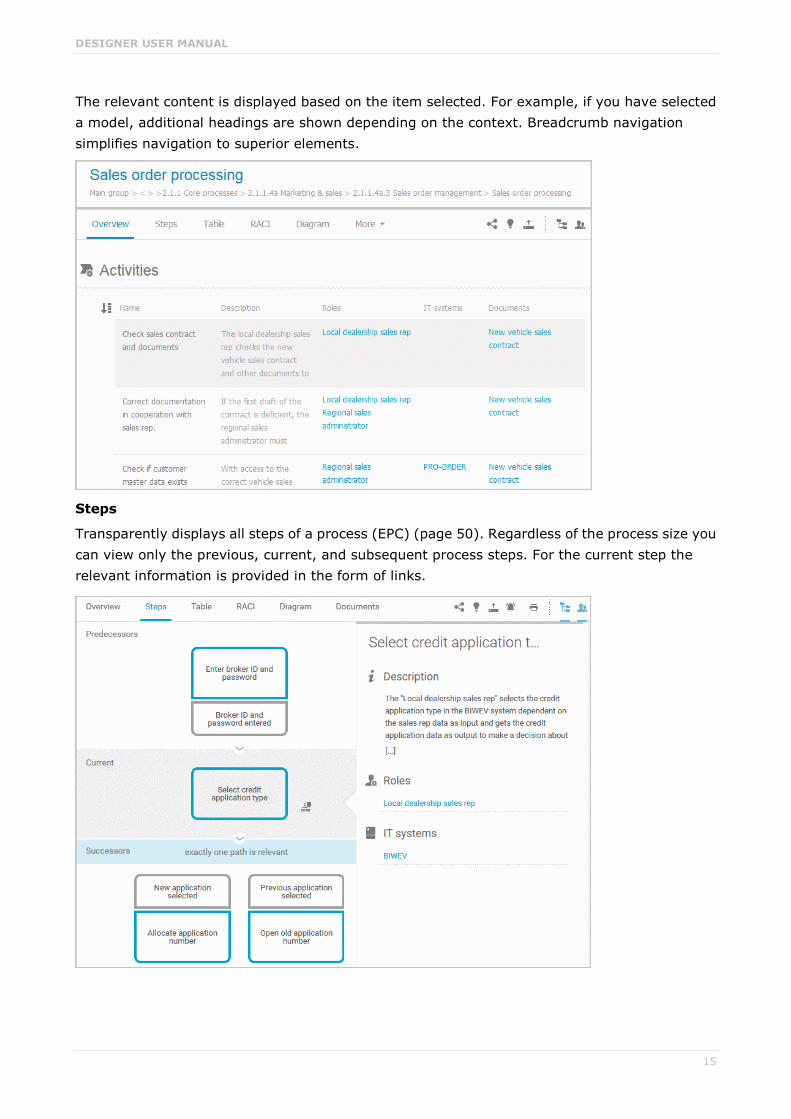
The relevant content is displayed based on the item selected. For example, if you have selected a model, additional headings are shown depending on the context. Breadcrumb navigation simplifies navigation to superior elements.
Steps
Transparently displays all steps of a process (EPC) (page 50). Regardless of the process size you can view only the previous, current, and subsequent process steps. For the current step the relevant information is provided in the form of links.
DESIGNER USER MANUAL
16
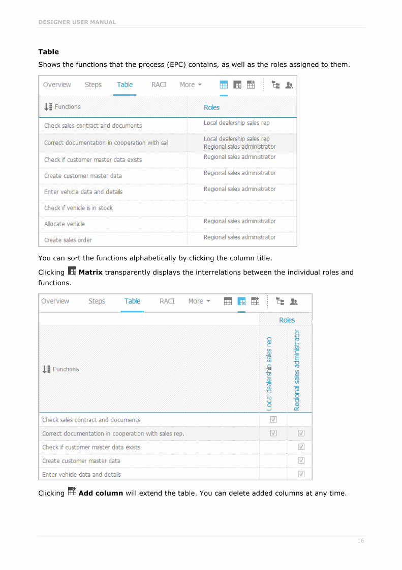
Table
Shows the functions that the process (EPC) contains, as well as the roles assigned to them.
You can sort the functions alphabetically by clicking the column title.
Clicking Matrix transparently displays the interrelations between the individual roles and functions.
Clicking Add column will extend the table. You can delete added columns at any time.

DESIGNER USER MANUAL
17
RACI
RACI matrices are displayed only if RACI information is available for this process (page 120). Using the button you can sort the matrices by process flow.

DESIGNER USER MANUAL
18
Diagram
Graphically displays the diagram in Model Viewer. Depending on the diagram type, different functions are available.
Using the functions of the view bar you can change the size of appearance. Navigate in the model using the small frame of the thumbnail view above the slider. Clicking the arrow head will hide the bar.
Click Properties to view all attributes specified. If you have selected an object, the attributes for that object are displayed. Click More to view related objects or occurrences. The model properties are shown if no object is selected.

DESIGNER USER MANUAL
19
To highlight objects in the diagram that meet a defined condition, click Highlight and On, and enable the criteria to be met.
The objects are then highlighted in the diagram. In this example the activity is highlighted because its check box is activated in the categories. All other objects are displayed in grayscale.
ASSIGNMENTS
If you click the assignment icon of an object in the diagram, or double-click an object with the assignment icon, all diagrams assigned are offered in a dialog for selection. If only one diagram
is assigned, that diagram opens directly. Assigned diagrams contain detailed information on the object that the diagrams are assigned to, for example.

DESIGNER USER MANUAL
20
Tasks
Shows your tasks, e.g., mini workflows or APG processes and opens them for editing in ARIS Process Board (page 5).

DESIGNER USER MANUAL
21
Transactions
Transactions are displayed if you are using Process-driven Management for SAP and if this function has been configured in the portal.
You can start (page 116) the transaction automatically via the default server in each row displaying a transaction code. Click the arrow head to display all registered SAP Servers. The default server selected is indicated by a check mark.
To start the transaction, click an SAP Server or a URL. The Login dialog opens.

DESIGNER USER MANUAL
22
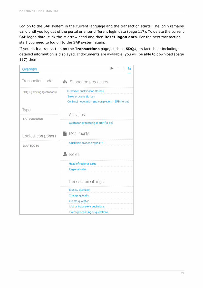
Log on to the SAP system in the current language and the transaction starts. The login remains valid until you log out of the portal or enter different login data (page 117). To delete the current SAP logon data, click the arrow head and then Reset logon data. For the next transaction start you need to log on to the SAP system again.
If you click a transaction on the Transactions page, such as SDQ1, its fact sheet including detailed information is displayed. If documents are available, you will be able to download (page 117) them.

DESIGNER USER MANUAL
23
Documents
Lists documents assigned to models or objects, for example, by the Link 1 - Link 4 attributes.
ARIS document storage enables you to manage and temporarily or permanently save documents.
Access restriction on folder level is possible in ARIS document storage. The documents saved there can be used during runtime of an executable process, e. g., attached to an e-mail.
All file formats are allowed for documents.
Temporary documents are deleted automatically after the executable process is terminated. Permanent documents are kept until they are deleted explicitly.
Depending on your license, you have read-access from ARIS to documents managed in third-party document management systems.
Note: You can view videos for some procedures in the help. If your browser is unable to open the quick videos within the help, please use a different browser. The videos are also available in ARIS Community (http://www.ariscommunity.com/help/quick-videos).
If you want to use the full range of functions of a document management system, including archiving and audit compliance, or you want to use very large numbers of documents, you can link Microsoft® Sharepoint 2013 to ARIS.
ARIS document storage as standalone component should be used for administrative purposes only. End users should access documents in the repository in ARIS Connect.

DESIGNER USER MANUAL
24
GROUP ITEMS OF UML ELEMENTS
Overview
The relevant content is displayed based on the item selected. If you have selected a group, the group content is displayed. Content that can be used to navigate to other content is displayed as links.
For example, if you have selected a UML element, additional headings are shown depending on the context. Breadcrumb navigation simplifies navigation to superior elements.

DESIGNER USER MANUAL
25
Relationships
Displays the relationships of the selected UML element as a link. If you click the link, the related element is displayed, highlighted in the tree, and the breadcrumb navigation adjusted.
Reused objects
Lists the objects that the selected element reuses as a link. If you click the link, the related element is displayed, highlighted in the tree, and the breadcrumb navigation adjusted.
Linked diagrams
Lists the diagrams with which the selected element is linked as a link. If you click the link, the related element is displayed, highlighted in the tree, and the breadcrumb navigation adjusted.
Presentations
Lists the diagrams in which the selected element occurs as a link. If you click the link, the related element is displayed, highlighted in the tree, and the breadcrumb navigation adjusted.
Stereotypes
Lists the stereotypes that were applied to the selected element as a link. If you click the link, the related element is displayed, highlighted in the tree, and the breadcrumb navigation adjusted.
Profiles
Lists the profiles that were applied to the selected element.
Tagged values
Lists the tagged values with which the selected element is linked as a link. If you click the link, the related element is displayed, highlighted in the tree, and the breadcrumb navigation adjusted.
Diagram
This entry is displayed if you have selected a UML diagram and displays the UML diagram in Model Viewer graphically.

DESIGNER USER MANUAL
26
3.1.1.1.3 Glossary
The Glossary page shows descriptions of business processes, roles, documents, and IT systems in tables. Depending on the selected context, you can list persons responsible, departments, business processes, and occurrences in business processes.
If you have both the ARIS Connect Viewer and Contribution license privileges, you can use
the Edit button to change values of specific items (page 110), create new or reuse existing items (page 105), as well as delete items (page 107).
Click an entry to navigate. The corresponding fact sheet opens.
You can reduce the number of items shown in the list or change the glossary page:

DESIGNER USER MANUAL
27
Choose items starting with the same letter
You can reduce the number of items shown in the glossary list.
Procedure
1. In the Classic configuration set (page 26) or the Default configuration set (page 45) of the portal, click Glossary.
2. Click Glossary letters in the Name cell of the table header. The Glossary letters bar opens.
3. Click on the relevant letter.
Only items starting with the same letter are shown.
Filter items based on name, description, and responsibility
You can reduce the number of items shown in the glossary list.
Procedure
1. In the Classic configuration set (page 26) or the Default configuration set (page 45) of the portal, click Glossary.
2. Click Filter in the table header. The text boxes to filter the list are opened.
3. Enter the relevant terms in one or more fields.
All items are listed whose attribute content contains a word beginning with the term entered. You can narrow down the search by entering terms in more than one text box.

DESIGNER USER MANUAL
28
Change the glossary page
If not all glossary entries fit on one page, you can switch to the page that contains the relevant glossary entry.
Procedure
1. In the Classic configuration set (page 26) or the Default configuration set (page 45) of the portal, click Glossary.
2. Click the relevant page number at the bottom of the page.
All items of the selected page are listed.

DESIGNER USER MANUAL
29
3.1.1.2 Default view
If you click Portal, you can view all information relevant to you.
If the administrator provides at least one database, this view shows all content relevant to you in a clear structure:
Processes (page 30)
Organization (page 41)
IT systems (page 42)
Glossary (page 45)
If your administrator has published multiple databases, these are available for selection
. You can switch between the published databases as required.
You only see information in the portal that is relevant to you. This is controlled in user management by administrators.
You can activate role filters (page 62) to further restrict this content. Role filters are available only if roles are assigned (page 61) to your user in models and the portal has been configured for the use of role filters.
Important for me
Displays processes in which the user logged in or their group is modeled, as well as application systems for which the user or user group is responsible. Processes are models of the EPC type (event-driven process chain).
My activities
Shows the current activities you are following in Collaboration or in the portal (page 191).

DESIGNER USER MANUAL
30
3.1.1.2.1 Processes
Quickly gain an overview of all processes that are relevant to you. Navigate via value-added chains to the process chains of the portal selected.
Depending on the contents selected and the type of a diagram, different functions are available.
Using the bar panel buttons Comment and Navigation, you can show or hide the Collaboration functions Follow (page 59) and Comment (page 58), as well as the Explorer tree. Thus, more space is available, for example, to show diagrams. The buttons of visible bars are indicated in color.
Click Share model to share models with other users (page 66). Click Submit change
request to send change requests to the process manager (page 57). The function Start governance process (page 59) is provided only if an executable process is available. Users with
the function privilege ARIS Connect Designer can change processes using the Edit button (page 70).

DESIGNER USER MANUAL
31
Overview
Displays the group content. Content that can be used to navigate to other content is displayed as links.
The relevant content is displayed based on the item selected. For example, if you have selected a model, additional headings are shown depending on the context. Breadcrumb navigation simplifies navigation to superior elements.

DESIGNER USER MANUAL
32
Steps
Transparently displays all steps of a process (EPC) (page 50). Regardless of the process size you can view only the previous, current, and subsequent process steps. For the current step the relevant information is provided in the form of links.

DESIGNER USER MANUAL
33
Table
Shows the functions that the process (EPC) contains, as well as the roles assigned to them.
You can sort the functions alphabetically by clicking the column title.
Clicking Matrix transparently displays the interrelations between the individual roles and functions.

DESIGNER USER MANUAL
34
Clicking Add column will extend the table. You can delete added columns at any time.
RACI
RACI matrices are displayed only if RACI information is available for this process (page 120). Using the button you can sort the matrices by process flow.

DESIGNER USER MANUAL
35
Diagram
Graphically displays the diagram in Model Viewer. Depending on the diagram type, different functions are available.
Using the functions of the view bar you can change the size of appearance. Navigate in the model using the small frame of the thumbnail view above the slider. Clicking the arrow head will hide the bar.
Click Properties to view all attributes specified. If you have selected an object, the attributes for that object are displayed. Click More to view related objects or occurrences. The model properties are shown if no object is selected.

DESIGNER USER MANUAL
36
To highlight objects in the diagram that meet a defined condition, click Highlight and On, and enable the criteria to be met.
The objects are then highlighted in the diagram. In this example the activity is highlighted because its check box is activated in the categories. All other objects are displayed in grayscale.
ASSIGNMENTS
If you click the assignment icon of an object in the diagram, or double-click an object with the assignment icon, all diagrams assigned are offered in a dialog for selection. If only one diagram
is assigned, that diagram opens directly. Assigned diagrams contain detailed information on the object that the diagrams are assigned to, for example.

DESIGNER USER MANUAL
37
Tasks
Shows your tasks, e.g., mini workflows or APG processes and opens them for editing in ARIS Process Board (page 5).

DESIGNER USER MANUAL
38
Transactions
Transactions are displayed if you are using Process-driven Management for SAP and if this function has been configured in the portal.
You can start (page 116) the transaction automatically via the default server in each row displaying a transaction code. Click the arrow head to display all registered SAP Servers. The default server selected is indicated by a check mark.
To start the transaction, click an SAP Server or a URL. The Login dialog opens.
DESIGNER USER MANUAL
39
Log on to the SAP system in the current language and the transaction starts. The login remains valid until you log out of the portal or enter different login data (page 117). To delete the current SAP logon data, click the arrow head and then Reset logon data. For the next transaction start you need to log on to the SAP system again.
If you click a transaction on the Transactions page, such as SDQ1, its fact sheet including detailed information is displayed. If documents are available, you will be able to download (page 117) them.

DESIGNER USER MANUAL
40
Documents
Lists documents assigned to models or objects, for example, by the Link 1 - Link 4 attributes.
ARIS document storage enables you to manage and temporarily or permanently save documents.
Access restriction on folder level is possible in ARIS document storage. The documents saved there can be used during runtime of an executable process, e. g., attached to an e-mail.
All file formats are allowed for documents.
Temporary documents are deleted automatically after the executable process is terminated. Permanent documents are kept until they are deleted explicitly.
Depending on your license, you have read-access from ARIS to documents managed in third-party document management systems.
Note: You can view videos for some procedures in the help. If your browser is unable to open the quick videos within the help, please use a different browser. The videos are also available in ARIS Community (http://www.ariscommunity.com/help/quick-videos).
If you want to use the full range of functions of a document management system, including archiving and audit compliance, or you want to use very large numbers of documents, you can link Microsoft® Sharepoint 2013 to ARIS.
ARIS document storage as standalone component should be used for administrative purposes only. End users should access documents in the repository in ARIS Connect.
ARIS video tutorial ARIS Connect - Process improvement (http://www.ariscommunity.com/videos/aris-connect-process-improvement-everyone)

DESIGNER USER MANUAL
41
3.1.1.2.2 Organization
Quickly gain an overview of the organizational structure. Navigate to all organizational elements of the portal selected. Breadcrumbs simplify navigation to superior elements.
The Overview gives you access to the relevant information. For example, if you click a supported process, the process information (page 30) is displayed. IT information (page 42) is available when clicking a system in use.
Using the bar panel buttons Comment and Navigation, you can show or hide the Collaboration functions Follow (page 59) and Comment (page 58), as well as the Explorer tree. Thus, more space is available, for example, to show diagrams. The buttons of visible bars are indicated in color.
The function Start governance process (page 59) is provided only if an executable process is available.

DESIGNER USER MANUAL
42
3.1.1.2.3 IT systems
Quickly obtain an overview of the IT landscape. Use the Explorer tree to navigate to all IT systems of the portal. Breadcrumbs simplify navigation to selected elements.
Depending on the contents selected, different functions are available.
Using the bar panel buttons Comment and Navigation, you can show or hide the Collaboration functions Follow (page 59) and Comment (page 58), as well as the Explorer tree. Thus, more space is available, for example, to show diagrams. The buttons of visible bars are indicated in color.
Click Share model to share models with other users (page 66). Click Submit change
request to send change requests to the process manager (page 57). The function Start governance process (page 59) is provided only if an executable process is available. Users with
the ARIS Connect Designer function privilege can change processes (page 70) using the Edit button. If you have both the ARIS Connect Viewer and Contribution license privileges,
you can use the Edit button to change values of specific items (page 110), create new or reuse existing items (page 105), as well as delete items (page 107).
Overview
The Overview gives you access to the relevant information. If you do not select any items in Explorer, all IT systems are listed in alphabetical order.

DESIGNER USER MANUAL
43
Diagram
All information is also available via the Application system type diagram model type containing all IT systems.
Using the functions of the view bar you can change the size of appearance. Navigate in the model using the small frame of the thumbnail view above the slider. Clicking the arrow head will hide the bar.
Click Properties to view all attributes specified. If you have selected an object, the attributes for that object are displayed. Click More to view related objects or occurrences. The model properties are shown if no object is selected.
If you navigate by clicking an assignment icon of an IT system, all diagrams assigned are offered for selection. These diagrams provide detailed information on the given IT system, as well as on the related roles, persons, and items.

DESIGNER USER MANUAL
44
IT system fact sheet
If you click an IT system in the Explorer tree or Overview, the IT system fact sheet provides you with important information at a glance.

DESIGNER USER MANUAL
45
3.1.1.2.4 Glossary
The Glossary page shows descriptions of business processes, roles, documents, and IT systems in tables. Depending on the selected context, you can list persons responsible, departments, business processes, and occurrences in business processes.
If you have both the ARIS Connect Viewer and Contribution license privileges, you can use
the Edit button to change values of specific items (page 110), create new or reuse existing items (page 105), as well as delete items (page 107).
Click an entry to navigate. The corresponding fact sheet opens.
You can reduce the number of items shown in the list or change the glossary page:

DESIGNER USER MANUAL
46
Choose items starting with the same letter
You can reduce the number of items shown in the glossary list.
Procedure
1. In the Classic configuration set (page 26) or the Default configuration set (page 45) of the portal, click Glossary.
2. Click Glossary letters in the Name cell of the table header. The Glossary letters bar opens.
3. Click on the relevant letter.
Only items starting with the same letter are shown.
Filter items based on name, description, and responsibility
You can reduce the number of items shown in the glossary list.
Procedure
1. In the Classic configuration set (page 26) or the Default configuration set (page 45) of the portal, click Glossary.
2. Click Filter in the table header. The text boxes to filter the list are opened.
3. Enter the relevant terms in one or more fields.
All items are listed whose attribute content contains a word beginning with the term entered. You can narrow down the search by entering terms in more than one text box.

DESIGNER USER MANUAL
47
Change the glossary page
If not all glossary entries fit on one page, you can switch to the page that contains the relevant glossary entry.
Procedure
4. In the Classic configuration set (page 26) or the Default configuration set (page 45) of the portal, click Glossary.
5. Click the relevant page number at the bottom of the page.
All items of the selected page are listed.
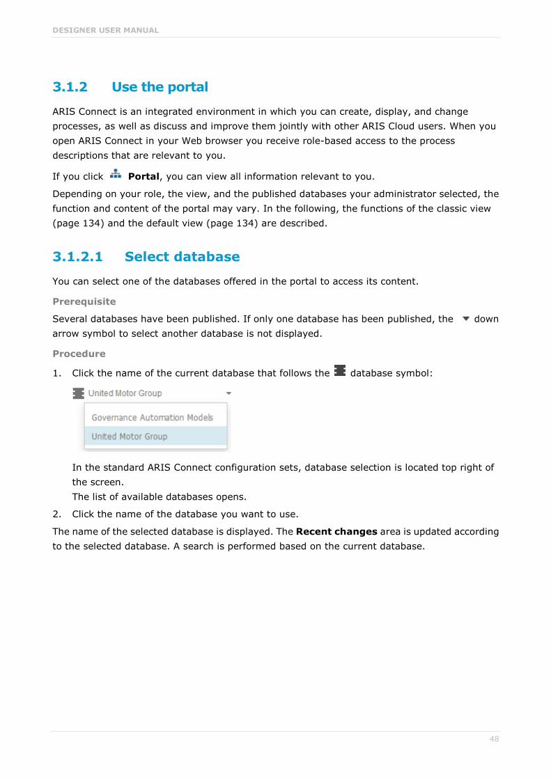
DESIGNER USER MANUAL
48
3.1.2 Use the portal
ARIS Connect is an integrated environment in which you can create, display, and change processes, as well as discuss and improve them jointly with other ARIS Cloud users. When you open ARIS Connect in your Web browser you receive role-based access to the process descriptions that are relevant to you.
If you click Portal, you can view all information relevant to you.
Depending on your role, the view, and the published databases your administrator selected, the function and content of the portal may vary. In the following, the functions of the classic view (page 134) and the default view (page 134) are described.
3.1.2.1 Select database
You can select one of the databases offered in the portal to access its content.
Prerequisite
Several databases have been published. If only one database has been published, the down arrow symbol to select another database is not displayed.
Procedure
1. Click the name of the current database that follows the database symbol:
In the standard ARIS Connect configuration sets, database selection is located top right of the screen. The list of available databases opens.
2. Click the name of the database you want to use.
The name of the selected database is displayed. The Recent changes area is updated according to the selected database. A search is performed based on the current database.

DESIGNER USER MANUAL
49
3.1.2.2 Navigate
With the help of hierarchies, administrators control how portal users can quickly navigate to relevant information. These hierarchies map the relationships between superior and subordinate items.
In the example for the default view, the Processes, Organization, and IT systems hierarchies are defined. All processes subordinate to the current process are displayed in the colored area.
In the diagrams, navigate to assigned diagrams by clicking an object's assignment icon, or by double-clicking an object with the assignment icon. All assigned diagrams are offered for selection in a dialog. If only one diagram is assigned, that diagram opens directly. Assigned diagrams contain detailed information on the object that the diagrams are assigned to, for example.

DESIGNER USER MANUAL
50
3.1.2.3 Navigate step by step
You can easily follow the process flow in process models of the EPC type. Predecessor and successor as well as the attributes of the selected object are displayed.
Procedure
1. In the Groups area (page 14), select a model of the EPC type. You are offered the steps of the EPC.
2. Click the steps. The first event of the process is shown at the top. It does not have a predecessor, therefore, no object is placed in this field. Below, the event's successor is output. To the right, the attributes are shown.
3. Click the successor. The event as a predecessor is moved to the field above, the succeeding object is placed in the middle, and its successors are visible in the lower field. The attributes of this object are now visible. If event and function precede or succeed each other, they are displayed together.
You navigate through a process step by step.
3.1.2.4 Choose glossary items starting with the same letter
You can reduce the number of items shown in the glossary list.
Procedure
1. In the Classic configuration set (page 26) or the Default configuration set (page 45) of the portal, click Glossary.
2. Click Glossary letters in the Name cell of the table header. The Glossary letters bar opens.
3. Click on the relevant letter.
Only items starting with the same letter are shown.

DESIGNER USER MANUAL
51
3.1.2.5 Filter glossary items based on name, description, and responsibility
You can reduce the number of items shown in the glossary list.
Procedure
1. In the Classic configuration set (page 26) or the Default configuration set (page 45) of the portal, click Glossary.
2. Click Filter in the table header. The text boxes to filter the list are opened.
3. Enter the relevant terms in one or more fields.
All items are listed whose attribute content contains a word beginning with the term entered. You can narrow down the search by entering terms in more than one text box.
3.1.2.6 Remove glossary filter
You can easily remove the glossary filter.
Prerequisite
You have filtered the glossary content (page 51).
Procedure
Click Filter in the table header. The text boxes to filter the list are closed and all glossary items are shown.
You have removed the glossary filter.

DESIGNER USER MANUAL
52
3.1.2.7 Change the glossary page
If not all glossary entries fit on one page, you can switch to the page that contains the relevant glossary entry.
Procedure
1. In the Classic configuration set (page 26) or the Default configuration set (page 45) of the portal, click Glossary.
2. Click the relevant page number at the bottom of the page.
All items of the selected page are listed.
3.1.2.8 Switch from Steps to Diagram
You can switch from the Steps fact sheet to the Diagram fact sheet where the current object symbol is selected.
Procedure
1. Click Groups (page 14) in the classic view (page 134) or Processes (page 30) in the default view (page 134).
2. Select the required model in the navigation. The fact sheets are shown.
3. Activate the Steps fact sheet and navigate to the relevant step.
4. Click Show in model next to the step.
The Diagram fact sheet is opened and the object symbol of the current step is selected. To return to the step fact sheet, click Steps. If you have selected another object in the Diagram fact sheet, this object is marked in the Steps fact sheet.

DESIGNER USER MANUAL
53
3.1.2.9 Print the graphic of the current model
In the portal, you can print the graphic of the current model as PDF.
Procedure
1. Click Groups (page 14) in the classic view (page 134) or Processes (page 30) in the default view (page 134).
2. Select the required model in the navigation. The fact sheets are shown.
3. Click Print graphic as PDF. The Select output options dialog opens.
4. Specify your settings.
5. Click OK. After report generation, the Print graphic as PDF dialog opens.
6. Click Download result. Using the following dialog, open the file in a PDF viewer or save it.
In the portal, you have printed the graphic of the current model as PDF.
To the left of the user name, a notification is inserted. Click the notification icon and Export graphic as PDF to download the result again. The result is also listed on the Reports bar. If you select the Diagram fact sheet, you can open the Reports bar and download the printed model graphic as PDF.
3.1.2.10 Display the current method filter
You can display the method filter that you use for the current database.
Procedure
1. Drag the mouse cursor over the database name located at the top right of the screen.
2. Leave the mouse cursor above the database name for a short time.
The filter name is displayed:

DESIGNER USER MANUAL
54
3.1.2.11 Generate report
The package includes various reports that you can start in the portal. Depending on the diagram open, reports are offered that provide a plausible evaluation for this context.
Procedure
1. Open ARIS Connect and log in with your user name and password.
2. Click Portal if it is not activated yet.
3. Depending on the view in use, click Groups or Processes.
4. Click Navigation if the navigation bar is not shown.
5. Click the model for which you want to create a report.
6. Click Diagram if not enabled yet.
7. Click Reports. The Reports bar opens showing the name of the item for which the report is generated.
All reports you can start for this diagram are displayed.
8. Click the down arrow next to the report name.
9. Select the relevant report.

DESIGNER USER MANUAL
55
10. Select the output format.
11. Click the output format, e.g., Output PDF.
12. Click Start. The report is started and a progress bar is displayed. After the report is complete, the Output object information dialog is opened.
13. Click Download result if you want to download the report immediately. You can choose whether to open or to save the report.
You have created a report. Only information you are authorized to view is included.
The report is shown in the Report results link list for downloading.
If you click the link, the report output opens.
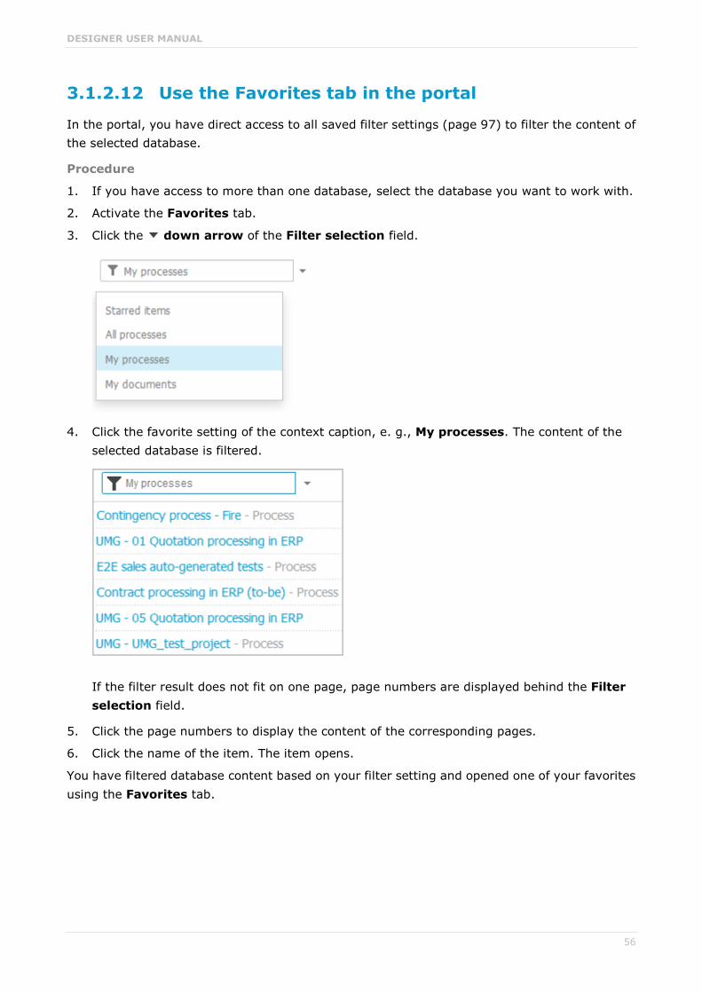
DESIGNER USER MANUAL
56
3.1.2.12 Use the Favorites tab in the portal
In the portal, you have direct access to all saved filter settings (page 97) to filter the content of the selected database.
Procedure
1. If you have access to more than one database, select the database you want to work with.
2. Activate the Favorites tab.
3. Click the down arrow of the Filter selection field.
4. Click the favorite setting of the context caption, e. g., My processes. The content of the selected database is filtered.
If the filter result does not fit on one page, page numbers are displayed behind the Filter selection field.
5. Click the page numbers to display the content of the corresponding pages.
6. Click the name of the item. The item opens.
You have filtered database content based on your filter setting and opened one of your favorites using the Favorites tab.

DESIGNER USER MANUAL
57
3.1.2.13 Show where object occurrences are used
You can display where occurrences of an object are used and select the required occurrence using the navigation controls.
Procedure
1. Click Navigation. The Groups area opens.
2. Open the group where the required model is stored.
3. Click the name of the model. The factsheet of the model opens.
4. Click Diagram. The Diagram view opens.
5. Select the required object in the Diagram view.
6. Click Properties. The Properties bar opens.
7. Click the Occurrences tab. The occurrences of the selected object are listed. If more than one occurrence exists in the current model, the number of the selected occurrence and the total number of occurrences are displayed next to the object name.
8. Click the left or right arrow to navigate to the next occurrence in the model. The next occurrence is selected and its number updated.
9. To directly select an occurrence, expand the drop-down list and click the occurrence number.
10. To open a model that contains an occurrence of the selected object, click the name of the model in the In other models area. The model opens and the first occurrence of the object is selected. If there is no diagram view for the occurrence, the first fact sheet tab is shown, e.g., Overview.
In the In other models area, all models are displayed to which you have at least read access.
You have switched between the occurrences of an object using the navigation controls.
3.1.2.14 Submit change request
You can send change requests for models to the person responsible.
Prerequisites You have at least the ARIS Connect Viewer license privilege.
The Person responsible model attribute must be specified for the relevant model with a user name that exists in the user management.
When using Microsoft® Internet Explorer version 8, the compatibility mode must be disabled.
Procedure
1. Open ARIS Connect and log in with your user name and password.
2. Click Portal if it is not activated yet.
3. Depending on the view in use, click Groups or Processes.
4. Click Navigation if the navigation bar is not shown.

DESIGNER USER MANUAL
58
5. Click the model for which you want to submit a change request.
6. Click Submit change request. The dialog opens.
7. Enter a title and a description for your request.
8. Select the priority with which the request is to be handled.
9. Add any relevant documents, graphics, etc. that could be used as a basis for editing.
10. Click Send. A completion message is displayed.
11. Click OK.
The person responsible receives the change request by e-mail with a link to the relevant model and a link to edit the associated task in ARIS Process Board.
Once the person responsible has processed the request, the applicant receives a message by e-mail.
As soon as the first change request is made, the ARIS Connect Governance Inbox database is automatically created in ARIS. It contains a Requirements inbox for each person responsible with a model of the Requirements tree type. An object of the Requirement type is created for each change request. As the process continues, the realization status of the object is automatically changed depending on which status the person responsible has selected (Approve, Reject). This enables all change requests to be monitored in the ARIS Connect Governance Inbox database.
All users can select the language to be used for the notification in their profile in ARIS Connect.
This workflow is a part of ARIS Connect. It can be customized, if required. For example, you can change e-mail texts, add notifications, make changes to dialogs, etc. The integration of complex workflows (standard RCM, change management, etc.) requires the ARIS Design Server license or ARIS Connect Server extension pack: Process Governance.
3.1.2.15 Comment on portal content
Add comments to models and post information that could be of interest to your colleagues.
Prerequisite
You have the required access privilege (page 202) in ARIS Architect.
1. Navigate to a process.
2. Click Comment in the bar panel if the bar is not activated yet.
3. Enter or copy your text into the input field. Up to 250 characters are available. If you also want to add a link, note that the characters in the link are counted towards the 250 available characters.
4. Click Tag.
5. Enter the words to be used as keywords (page 201) in the tag input box, e.g., BPM. Alternatively, select an existing tag from the list of tags. It is displayed as soon as you enter a letter that is part of an existing tag. Press the Enter key after each keyword.
6. Click Link.
7. Insert a link to a Web site that contains more detailed information.

DESIGNER USER MANUAL
59
8. Click Add link. The link is checked and added.
9. Click File. The Select document dialog is displayed.
10. Click Upload new document to upload one of your own documents. The dialog opens.
11. Select the file you want to upload and enter the relevant additional information.
12. Click Upload.
13. Enable the check box of the document you want to add to your post.
14. Click OK.
Your comment is posted.
3.1.2.16 Start governance process
You can start governance processes from the portal.
Prerequisite
The Start governance process function is provided only if an executable process is available, and if the item for which the governance process is to be started is defined as the execution context (page 137).
Procedure
1. Navigate to the process or object for which you want to start the governance process.
2. Click Start governance process. If multiple processes are available, they will be displayed for selection.
3. Click the executable process.
The executable process will start.
3.1.2.17 Follow processes in the portal
Follow processes or other models to be informed about updates in the portal and in Collaboration.
Procedure
1. Navigate to a process.
2. Click Comment in the bar panel if the bar is not activated yet.
3. Click Follow.
The content you are following is displayed in the portal under My activities and in Collaboration
under My portal feeds. To stop following content, click the relevant link, and in the content displayed click Unfollow.

DESIGNER USER MANUAL
60
3.1.2.18 Request feedback on processes
You can request feedback on processes from other users.
Prerequisite You have at least the ARIS Connect Viewer license privilege.
When using Microsoft® Internet Explorer version 8, the compatibility mode must be disabled.
Procedure
1. Open ARIS Connect and log in with your user name and password.
2. Click Portal if it is not activated yet.
3. Depending on the view in use, click Groups or Processes.
4. Click Navigation if the navigation bar is not shown.
5. Click the model for which you want feedback.
6. Click Comment if the Comment bar is not open yet.
7. Enter your comment in the box provided.
8. Click Tag.
9. Enter the words to be used as keywords (page 201) in the tag input box, e.g., BPM. Alternatively, select an existing tag from the list of tags. It is displayed as soon as you enter a letter that is part of an existing tag. Press the Enter key after each keyword.
10. Click Link.
11. Insert a link to a Web site that contains more detailed information.
12. Click Add link. The link is checked and added.
13. Click File. The Select document dialog is displayed.
14. Click Upload new document to upload one of your own documents. The dialog opens.
15. Select the file you want to upload and enter the relevant additional information.
16. Click Upload.
17. Enable the check box of the document you want to add to your post.
18. Click OK.
The comment is displayed below the process and can be commented on by other users.
All users can select the language to be used for the notification in their profile in ARIS Connect.
This workflow is a part of ARIS Connect. It can be customized, if required. For example, you can change e-mail texts, add notifications, make changes to dialogs, etc. The integration of complex workflows (standard RCM, change management, etc.) requires the ARIS Design Server license or ARIS Connect Server extension pack: Process Governance.

DESIGNER USER MANUAL
61
3.1.3 Use roles
You use role filters to further restrict this content. Role filters are available only if roles are assigned (page 61) to your user in models and the portal has been configured for the use of role filters.
3.1.3.1 Assign roles
In order to enable users to use role filters (page 138) in the portal, you must assign the corresponding roles to the users.
Prerequisites You have the User administrator function privilege.
You have the ARIS Connect Designer license privilege.
Procedure
1. Click Portal.
2. Open a diagram containing an occurrence of the relevant role, e.g., Regional sales department specialist.
3. Click Edit. The diagram opens on a separate tab for editing.
4. Select the Role type object and click Properties. The attributes are displayed.
5. Move the mouse pointer to the User/User group association attribute.
6. Click Select user. The Select user(s)/user group(s) dialog opens.
7. Enter the user name in the Filter box.
8. Enable the check box for the user, and click OK.
9. Save the changes and close the diagram.
The role has been assigned to the user.
If this user activates (page 62) the role filter, only information from models in which the selected role occurs will be displayed.

DESIGNER USER MANUAL
62
3.1.3.2 Activate role filter
Using role filters, you restrict the content in such a way that you only see information from processes in which certain roles are involved.
Prerequisite
A role has been assigned (page 61) to your user.
Procedure
1. Click Select role filter to the left of your user name.
2. Click On and activate the relevant role.
In the portal, you now see information only for the models in which the selected role occurs. Models of the Value-added chain diagram type are always shown with an active role filter regardless of whether or not the model contains the role. When you open a diagram, all information is displayed unfiltered. You can also navigate using assignments. If you view processes step by step (page 50), all steps are displayed. The detailed information about the satellites is filtered according to the selected role. Tables, fact sheets, and RACI matrices contain only role-specific information. You only access filtered information via the search and the navigation.
If you click Off, the role filter is deactivated and you see your entire content again.
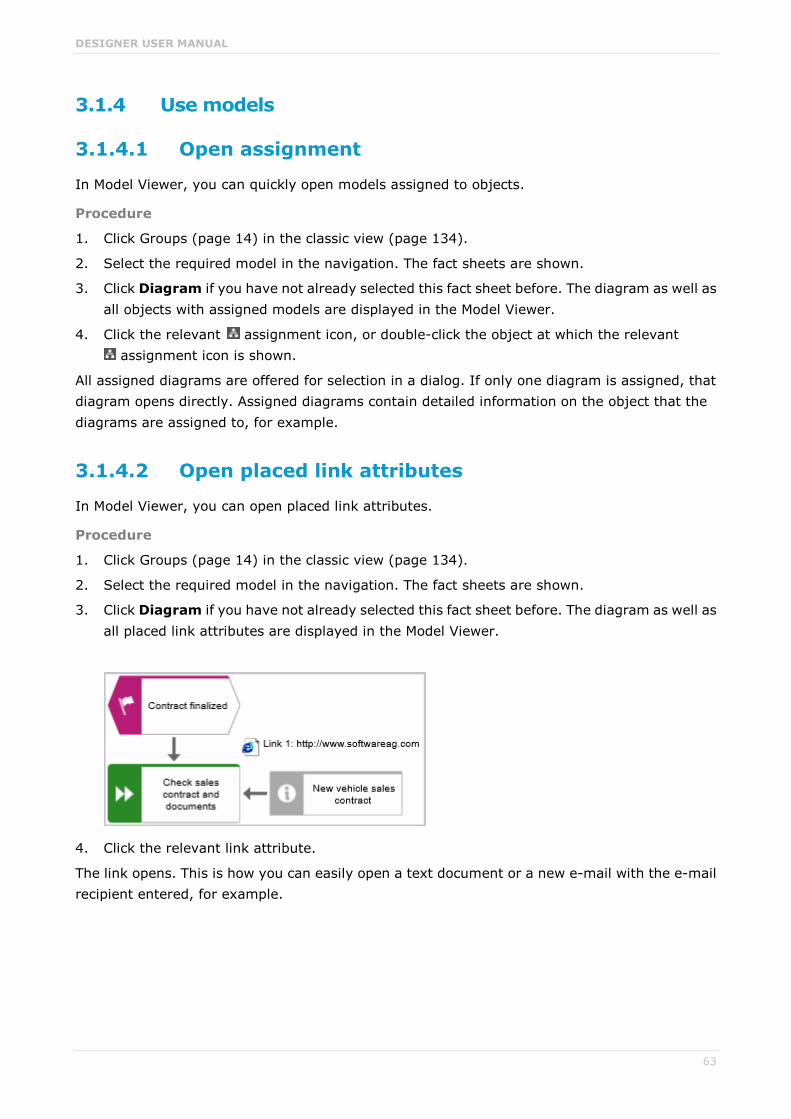
DESIGNER USER MANUAL
63
3.1.4 Use models
3.1.4.1 Open assignment
In Model Viewer, you can quickly open models assigned to objects.
Procedure
1. Click Groups (page 14) in the classic view (page 134).
2. Select the required model in the navigation. The fact sheets are shown.
3. Click Diagram if you have not already selected this fact sheet before. The diagram as well as all objects with assigned models are displayed in the Model Viewer.
4. Click the relevant assignment icon, or double-click the object at which the relevant assignment icon is shown.
All assigned diagrams are offered for selection in a dialog. If only one diagram is assigned, that diagram opens directly. Assigned diagrams contain detailed information on the object that the diagrams are assigned to, for example.
3.1.4.2 Open placed link attributes
In Model Viewer, you can open placed link attributes.
Procedure
1. Click Groups (page 14) in the classic view (page 134).
2. Select the required model in the navigation. The fact sheets are shown.
3. Click Diagram if you have not already selected this fact sheet before. The diagram as well as all placed link attributes are displayed in the Model Viewer.
4. Click the relevant link attribute.
The link opens. This is how you can easily open a text document or a new e-mail with the e-mail recipient entered, for example.

DESIGNER USER MANUAL
64
3.1.4.3 Switch from Steps to Diagram
You can switch from the Steps fact sheet to the Diagram fact sheet where the current object symbol is selected.
Procedure
1. Click Groups (page 14) in the classic view (page 134) or Processes (page 30) in the default view (page 134).
2. Select the required model in the navigation. The fact sheets are shown.
3. Activate the Steps fact sheet and navigate to the relevant step.
4. Click Show in model next to the step.
The Diagram fact sheet is opened and the object symbol of the current step is selected. To return to the step fact sheet, click Steps. If you have selected another object in the Diagram fact sheet, this object is marked in the Steps fact sheet.
3.1.4.4 Print the graphic of the current model
In the portal, you can print the graphic of the current model as PDF.
Procedure
1. Click Groups (page 14) in the classic view (page 134) or Processes (page 30) in the default view (page 134).
2. Select the required model in the navigation. The fact sheets are shown.
3. Click Print graphic as PDF. The Select output options dialog opens.
4. Specify your settings.
5. Click OK. After report generation, the Print graphic as PDF dialog opens.
6. Click Download result. Using the following dialog, open the file in a PDF viewer or save it.
In the portal, you have printed the graphic of the current model as PDF.
To the left of the user name, a notification is inserted. Click the notification icon and Export graphic as PDF to download the result again. The result is also listed on the Reports bar. If you select the Diagram fact sheet, you can open the Reports bar and download the printed model graphic as PDF.

DESIGNER USER MANUAL
65
3.1.4.5 Ask for model approval
Ask the person in charge to approve the models you changed so that the changed models can be made available to all users.
Prerequisite You have at least the ARIS Connect Viewer license privilege.
When using Microsoft® Internet Explorer version 8, the compatibility mode must be disabled.
Procedure
1. Open ARIS Connect and log in with your user name and password.
2. Click Portal if it is not activated yet.
3. Depending on the view in use, click Groups or Processes.
4. Click Navigation if the navigation bar is not shown.
5. Click the name of the model you want to edit.
6. Click Edit > Edit model. The model opens in the Model Editor on an individual tab.
7. Make the required changes.
8. Click Collaboration if it is not activated yet.
9. Click Request approval. The Confirmation dialog opens for you to confirm that the model changes are to be saved and the model is to be reopened read-only.
10. Click OK. The model reopens read-only and the Request approval dialog is displayed.
11. If required, select a person in charge to approve the model if the Person responsible attribute has not been specified at the model.
12. Enter a comment to explain the approval request.
13. Click Send. A completion message is displayed.
14. Click OK.
The person responsible receives an e-mail with the relevant information and a link to the associated task in ARIS Process Board. If the person responsible approves the changes, the model is automatically published and the current version is provided.
Until then, only you and other modelers can view your changes.
All users can select the language to be used for the notification in their profile in ARIS Connect.
This workflow is a part of ARIS Connect. It can be customized, if required. For example, you can change e-mail texts, add notifications, make changes to dialogs, etc. The integration of complex workflows (standard RCM, change management, etc.) requires the ARIS Design Server license or ARIS Connect Server extension pack: Process Governance.
DESIGNER USER MANUAL
66
3.1.4.6 Share model
You can share models with other users.
Prerequisite You have at least the ARIS Connect Viewer license privilege.
When using Microsoft® Internet Explorer version 8, the compatibility mode must be disabled.
Procedure
1. Open ARIS Connect and log in with your user name and password.
2. Click Portal if it is not activated yet.
3. Depending on the view in use, click Groups or Processes.
4. Click Navigation if the navigation bar is not shown.
5. Click the model you want to send to another user.
6. Click Share model. The dialog opens.
7. Select the user you want to share the model with.
8. Enable Send copy to me to receive a copy of the message, if required.
9. You can also enter a subject and a comment.
10. Click Send.
The selected user receives an e-mail containing the information you entered and a link to the corresponding model.
All users can select the language to be used for the notification in their profile in ARIS Connect.
This workflow is a part of ARIS Connect. It can be customized, if required. For example, you can change e-mail texts, add notifications, make changes to dialogs, etc. The integration of complex workflows (standard RCM, change management, etc.) requires the ARIS Design Server license or ARIS Connect Server extension pack: Process Governance.

DESIGNER USER MANUAL
67
3.1.4.7 Inform owner of change
You can inform the model owner of model changes you have made in the portal (page 104). The process owner is automatically determined by the attribute Person responsible.
Prerequisite You have the ARIS Connect Viewer and Contribution license privileges, or the ARIS
Connect Designer license privilege.
When using Microsoft® Internet Explorer version 8, the compatibility mode must be disabled.
Procedure
1. Open ARIS Connect and log in with your user name and password.
2. Click Portal if it is not activated yet.
3. Depending on the view in use, click Groups or Processes.
4. Click Navigation if the navigation bar is not shown.
5. Navigate to the items and change the relevant attributes (page 104). Depending on the attributes, various editing options (page 112) are available.
6. Click Inform owner of change. The Inform of change dialog opens.
7. Insert a change description
8. Click Submit. The Information dialog opens.
9. Enable the Do not show this message again check box if you do not want to be informed again by the dialog when executing the mini workflow more than once during the current session.
10. Click OK.
The process owner receives an e-mail containing the information you entered. If he submits the human task, you will be informed via e-mail.
This workflow is a part of ARIS Connect. It can be customized, if required. For example, you can change e-mail texts, add notifications, make changes to dialogs, etc. The integration of complex workflows (standard RCM, change management, etc.) requires the ARIS Design Server license or ARIS Connect Server extension pack: Process Governance.

DESIGNER USER MANUAL
68
3.1.4.8 Generate report
You can generate and download a report for the open model.
Procedure
1. Show the Reports bar ( ).
2. Click the drop-down list box to display the list of available reports.
3. Leave the mouse pointer on the name of a report if you want to display its description.
4. Click the name of the relevant report.
5. Click the report output format, e.g., Output PDF if you want to output the report in the first available format (page 154). To select a different report format, click the Down arrow next to Output PDF and select the format you want to use. The Output PDF button is given the name of the selected report format.
6. Click the button. The report is created and listed in the Reports bar (page 264).
7. Click the name of the listed report to download and open the report.
You generated the report for the open model.

DESIGNER USER MANUAL
69
3.1.4.9 Create model
You can quickly and easily create new models.
Prerequisites You have the ARIS Connect Designer license privilege.
The classic configuration set or modification set based on it is selected for the portal.
The relevant model type must be included in the database filter. If this is not the case, the portal page is displayed again after the Create model dialog closes.
Procedure
1. Open ARIS Connect and log in with your user name and password.
2. Click Portal if it is not activated yet.
3. Click Create model on the Home tab. The dialog opens.
4. Enter a name for the new model in the Model name box.
5. Click the Model type box and enter part of the model type name. All model types (page 269) are displayed whose names contain the term you entered.
6. Select the required model type. The Target area displays the database and group names. This is where the new model will be stored.
7. Click Change if you want to store the model in a different database and/or group. The Select target group dialog opens.
8. Select the required database in the Database box.
9. Select the required group.
10. Click OK. The Select target group dialog closes.
11. Check your input.
12. Click OK. The Create model dialog closes.
The model is created and opens in a new tab (page 212).

DESIGNER USER MANUAL
70
3.1.4.10 Edit models
You can edit models in ARIS Connect.
Prerequisite You have the ARIS Connect Designer privilege.
When using Microsoft® Internet Explorer version 8, the compatibility mode must be disabled.
Procedure
1. Open ARIS Connect and log in with your user name and password.
2. Click Portal if it is not activated yet.
3. Depending on the view in use, click Groups or Processes.
4. Click Navigation if the navigation bar is not shown.
5. Click the name of the model you want to edit.
6. Click Edit > Edit model. The model opens in the Model Editor on an individual tab.
7. Make the required changes.
8. Click Save.
Your changes are saved in the model.
All users can select the language to be used for the notification in their profile in ARIS Connect.
This workflow is a part of ARIS Connect. It can be customized, if required. For example, you can change e-mail texts, add notifications, make changes to dialogs, etc. The integration of complex workflows (standard RCM, change management, etc.) requires the ARIS Design Server license or ARIS Connect Server extension pack: Process Governance.

DESIGNER USER MANUAL
71
3.1.4.11 Use matrix models
You can display a matrix model in ARIS Connect.
3.1.4.11.1 Open a matrix model in ARIS Connect
You can display a matrix model in ARIS Connect.
Prerequisite
You have a valid license for either Designer or ARIS Architect.
Procedure
1. Open ARIS Connect and log in with your user name and password.
2. Click Portal if it is not activated yet.
3. Click Groups.
4. Navigate to the group containing the relevant model.
5. Click the matrix model.
6. Click Matrix to display the matrix model.
The matrix model is displayed.
3.1.4.11.2 Display use of connections for a matrix model in ARIS Connect
You can obtain information about the connections used in a matrix model.
Procedure
1. Open a matrix model in ARIS Connect. (page 71)
2. Place the mouse cursor over a connection cell.
The list of connections used in the matrix model is displayed as a tooltip.

DESIGNER USER MANUAL
72
3.1.4.11.3 Show/Hide hierarchies in a matrix model in ARIS Connect
You can show or hide hierachies in a matrix model.
Procedure
1. Open a matrix model in ARIS Connect. (page 71)
2. Click the little arrow to expand or collapse the hierarchy. The hierarchy is shown or hidden accordingly.
The hierarchy is shown/hidden.
3.1.4.11.4 How are connections displayed?
In general, check marks indicate existing connections between objects in the matrix model. An asterisk indicates that there is more than one connection between two objects. The following display options are also available:
Indication of the direction of the connection
In the matrix model, a small arrow indicates the direction of a connection.
Indicates the direction from an icon placed in the column header to an icon placed in the row header.
Indicates the direction from an icon placed in the row header to an icon placed in the column header.
Indication of abbreviations
If an abbreviation is defined in Designer or ARIS Architect, this abbreviation is displayed instead of the check mark.

DESIGNER USER MANUAL
73
3.1.5 Handle documents
ARIS document storage enables you to manage and temporarily or permanently save documents.
3.1.5.1 Propose document
You can submit new documents on ARIS Connect content that is evaluated by the person responsible for the content and that may be linked to the contents.
Prerequisites You have at least the ARIS Connect Viewer license.
The Person responsible document attribute must be specified for the relevant document with a user name that exists in user management.
The person responsible must have the ARIS Connect Viewer or ARIS Connect Designer license.
Procedure
1. Open ARIS Connect and log in with your user name and password.
2. Click Portal if it is not activated yet.
3. Depending on the view in use, click Groups or Processes.
4. Click Navigation if the navigation bar is not shown.
5. Click a model or object.
6. Click Propose document. The Submit new document dialog opens.
7. Select the documents you want to submit.
8. Click Send.
The person responsible for the contents receives the approval request by e-mail. They can approve the document. It is then linked to the model or object. If they do not approve it, no link is created. The applicant receives a corresponding e-mail.
This workflow is a part of ARIS Connect. It can be customized, if required. For example, you can change e-mail texts, add notifications, make changes to dialogs, etc. The integration of complex workflows (standard RCM, change management, etc.) requires the ARIS Design Server license or ARIS Connect Server extension pack: Process Governance.

DESIGNER USER MANUAL
74
3.1.5.2 Link new documents to a model or object
You can link new documents with a model or object.
Prerequisite
You have the ARIS Connect Designer license.
Procedure
1. Open ARIS Connect and log in with your user name and password.
2. Click Portal if it is not activated yet.
3. Depending on the view in use, click Groups or Processes.
4. Click Navigation if the navigation bar is not shown.
5. Click the name of the model you want to edit.
6. Click Edit > Edit model. The model opens in the Model Editor on an individual tab.
7. Click Properties. The Properties bar opens.
8. Activate the Documents tab.
9. Click in the model background to add a document to the model or the relevant object to add a document to the object.
10. Click Add document. The dialog opens.
11. Navigate to the target folder.
12. Click Upload new document. The Select new document dialog opens.
13. Click Select file and select a document.
14. Enter a title and, if required, specify further document properties.
15. Click Upload.
16. Select the relevant documents and click OK.
The documents are linked with the model or object.

DESIGNER USER MANUAL
75
3.1.5.3 Add existing documents to a model or object
You can link documents from ARIS document storage or a document management system with a model or object.
Prerequisite
You have the ARIS Connect Designer license.
Procedure
1. Open ARIS Connect and log in with your user name and password.
2. Click Portal if it is not activated yet.
3. Navigate to a group and click a model.
4. Click Diagram if not enabled yet.
5. Click Edit. The model opens in the Model Editor on an individual tab.
6. Click Properties.
7. Activate the Documents tab.
8. Click in the model background or an object.
9. Click Add document.
10. Click the folder containing the relevant documents.
11. Select the relevant documents and click OK.
The documents are linked with the model or object.

DESIGNER USER MANUAL
76
3.1.5.4 Submit a change request for a document
You can send change requests for documents to the document manager for documents in ARIS Connect.
'DOCUMENTS' TAB
Prerequisites You have at least the ARIS Connect Viewer license.
The Person responsible document attribute must be specified for the relevant document with a user name that exists in user management.
The person responsible must have the ARIS Connect Viewer or ARIS Connect Designer license.
Procedure
1. Open ARIS Connect and log in with your user name and password.
2. Click Portal if it is not activated yet.
3. Depending on the view in use, click Groups or Processes.
4. Click Navigation if the navigation bar is not shown.
5. Click a model or object.
6. Activate the Documents tab.
7. Select the document for which you want to submit a change request.
8. Click Submit change request. The dialog opens.
9. Enter a title and a description for your request.
10. Select the priority with which the request is to be handled.
The document manager receives the change request by e-mail with a link to the relevant document and a link to edit the associated task in ARIS Process Board.
Once the document manager has processed the request, the applicant receives a message by e-mail.
If the change request is accepted, the person who is to implement the changes receives an e-mail including a link to the associated task in ARIS Process Board and the information added. After processing and approval - or rejection -, the applicant receives an e-mail including the information that the change requests have been implemented - or rejected.
This workflow is a part of ARIS Connect. It can be customized, if required. For example, you can change e-mail texts, add notifications, make changes to dialogs, etc. The integration of complex workflows (standard RCM, change management, etc.) requires the ARIS Design Server license or ARIS Connect Server extension pack: Process Governance.
DESIGNER USER MANUAL
77
IN A MODEL
Prerequisite
You have the ARIS Connect Designer license.
Procedure
1. Open ARIS Connect and log in with your user name and password.
2. Click Portal if it is not activated yet.
3. Open (page 70) the model that contains the document you want to submit a change request for.
4. Click Diagram if not enabled yet.
5. Click Edit > Contribute.
6. Click Properties.
7. Activate the Documents tab.
8. Select the document for which you want to submit a change request.
9. Click Submit change request. The dialog opens.
10. Enter a title and a description for your request.
11. Select the priority with which the request is to be handled.
12. Click Send.
You will automatically receive a confirmation notification.
The document manager receives the change request by e-mail with a link to the relevant document and a link to edit the associated task in ARIS Process Board.
Once the document manager has processed the request, the applicant receives a message by e-mail.
If the change request is accepted, the person who is to implement the changes receives an e-mail including a link to the associated task in ARIS Process Board and the information added. After processing and approval - or rejection -, the applicant receives an e-mail including the information that the change requests have been implemented - or rejected.
This workflow is a part of ARIS Connect. It can be customized, if required. For example, you can change e-mail texts, add notifications, make changes to dialogs, etc. The integration of complex workflows (standard RCM, change management, etc.) requires the ARIS Design Server license or ARIS Connect Server extension pack: Process Governance.

DESIGNER USER MANUAL
78
3.1.5.5 Have document approved
Ask the person in charge to approve the documents you changed so that the changed document can be made available to all users.
'DOCUMENTS' TAB
Prerequisites You have at least the ARIS Connect Viewer license.
The Person responsible document attribute must be specified for the relevant document with a user name that exists in user management.
The person responsible must have the ARIS Connect Viewer or ARIS Connect Designer license.
Procedure
1. Open ARIS Connect and log in with your user name and password.
2. Click Repository if it is not activated yet.
3. Activate the Documents tab.
4. Click the document you want to have approved.
5. Click Request approval. The dialog opens.
6. Enter a comment describing what you changed.
7. Click Send.
The person responsible receives an e-mail with the relevant information and a link to the associated task in ARIS Process Board. If the person responsible approves the changes, the current version of the document is made available in ARIS Connect (status APPROVED). The document is visible in the portal on the Documents tab. If rejected, the document receives the status REJECTED.
This workflow is a part of ARIS Connect. It can be customized, if required. For example, you can change e-mail texts, add notifications, make changes to dialogs, etc. The integration of complex workflows (standard RCM, change management, etc.) requires the ARIS Design Server license or ARIS Connect Server extension pack: Process Governance.
IN A MODEL
Prerequisite
You have the ARIS Connect Designer license.
Procedure
1. Open ARIS Connect and log in with your user name and password.
2. Click Portal if it is not activated yet.
3. Open (page 70) the model that contains the document that you want to have approved.
4. Click Properties.
5. Activate the Documents tab.

DESIGNER USER MANUAL
79
6. Select the relevant document.
7. Click Request approval. The dialog opens.
8. Click Send.
The person responsible receives an e-mail with the relevant information and a link to the associated task in ARIS Process Board. If the person responsible approves the changes, the current version of the document is made available in ARIS Connect (status APPROVED). The document is visible in the portal on the Documents tab. If rejected, the document receives the status REJECTED.
This workflow is a part of ARIS Connect. It can be customized, if required. For example, you can change e-mail texts, add notifications, make changes to dialogs, etc. The integration of complex workflows (standard RCM, change management, etc.) requires the ARIS Design Server license or ARIS Connect Server extension pack: Process Governance.
3.1.5.6 Share document
You can share documents with other users.
'DOCUMENTS' TAB
Prerequisites You have at least the ARIS Connect Viewer license.
The Person responsible document attribute must be specified for the relevant document with a user name that exists in user management.
The person responsible must have the ARIS Connect Viewer or ARIS Connect Designer license.
Procedure
1. Open ARIS Connect and log in with your user name and password.
2. Open ARIS Connect and log in with your user name and password.
3. Click Portal if it is not activated yet.
4. Depending on the view in use, click Groups or Processes.
5. Click Navigation if the navigation bar is not shown.
6. Click a document.
7. Activate the Documents tab.
8. Click the model you want to share.
9. Click Share document. The dialog opens.
10. Select the user you want to share the document with.
11. Enable Send copy to me to receive a copy of the message, if required.
12. You can also enter a subject and a comment.
13. Click Send.

DESIGNER USER MANUAL
80
The selected user receives an e-mail containing the information you entered and a link to the corresponding document.
This workflow is a part of ARIS Connect. It can be customized, if required. For example, you can change e-mail texts, add notifications, make changes to dialogs, etc. The integration of complex workflows (standard RCM, change management, etc.) requires the ARIS Design Server license or ARIS Connect Server extension pack: Process Governance.
IN A MODEL
Prerequisite
You have the ARIS Connect Designer license.
Procedure
1. Open ARIS Connect and log in with your user name and password.
2. Click Portal if it is not activated yet.
3. Open (page 70) the model that contains the document you want to submit a change request for.
4. Click Diagram if not enabled yet.
5. Click Edit > Contribute.
6. Click Properties.
7. Activate the Documents tab.
8. Select the document you want to share with another user.
9. Click Share document. The dialog opens.
10. Select the user you want to share the document with.
11. Enable Send copy to me to receive a copy of the message, if required.
12. You can also enter a subject and a comment.
13. Click Send.
The selected user receives an e-mail containing the information you entered and a link to the corresponding document.
This workflow is a part of ARIS Connect. It can be customized, if required. For example, you can change e-mail texts, add notifications, make changes to dialogs, etc. The integration of complex workflows (standard RCM, change management, etc.) requires the ARIS Design Server license or ARIS Connect Server extension pack: Process Governance.

DESIGNER USER MANUAL
81
3.1.5.7 Find a document
You can begin the search for items directly on the start page of ARIS Connect.
Procedure
1. If necessary, select the database (page 48) your search is to be based on.
2. Click in the Find box.
3. Enter the relevant term. A list with the first results (page 101) will be shown as you enter the term. As you complete the term, the list will be updated.
4. In the list, click the entry to which you want to navigate.
The document will open.
3.1.5.8 Rename document
You can rename a document.
Prerequisite
You have the Document management function privilege.
Procedure
1. Open ARIS document storage.
2. In the navigation, click the arrow next to ARIS document storage.
3. Click a folder in the navigation.
4. Click the relevant document.
5. Enter the new name in the File name box.
6. Click Save.
The name has been changed.

DESIGNER USER MANUAL
82
3.1.5.9 Show links of a document
You can display the links of a document, for example, the ARIS models in which the document is used.
Procedure
1. Open ARIS document storage.
2. Click a folder in the navigation.
3. Click the relevant document.
4. Click Open properties.
5. Click Relationships.
The properties of the document are displayed.
3.1.5.10 Remove document from a model or object
You can remove a document from a model or object.
Prerequisite
You have the ARIS Connect Designer license.
Procedure
1. Open ARIS Connect and log in with your user name and password.
2. Click Portal if it is not activated yet.
3. Open (page 70) the model you want to remove the document from.
4. Click Diagram if not enabled yet.
5. Click Edit > Contribute.
6. Click Properties.
7. Activate the Documents tab.
8. Click Remove selected document.
The document is removed from the model or object and no longer has any relationship to the model or object.

DESIGNER USER MANUAL
83
3.1.5.11 Show version of a document
You can show the version history of a document. If a document is changed and uploaded again, a version history is created automatically.
Procedure
1. Open ARIS document storage.
2. In the navigation, click the arrow next to ARIS document storage.
3. Click a folder in the navigation.
4. Click the relevant document.
5. Click Versions.
6. In the row of the relevant version, click Open version.
7. Select Open with in your browser.
The document opens if the software required for opening the document is available on your local system.

DESIGNER USER MANUAL
84
3.1.5.12 Handle document versions
3.1.5.12.1 Show version of a document
You can show the version history of a document. If a document is changed and uploaded again, a version history is created automatically.
Procedure
1. Open ARIS document storage.
2. In the navigation, click the arrow next to ARIS document storage.
3. Click a folder in the navigation.
4. Click the relevant document.
5. Click Versions.
6. In the row of the relevant version, click Open version.
7. Select Open with in your browser.
The document opens if the software required for opening the document is available on your local system.
3.1.5.12.2 Show version history
You can show the version history of a document. If a document is changed and uploaded again, a version history is created automatically.
Procedure
1. Open ARIS document storage.
2. In the navigation, click the arrow next to ARIS document storage.
3. Click a folder in the navigation.
4. Click the relevant document.
5. Click Versions.
The different versions of the document are displayed. The change description is in the Comment column.

DESIGNER USER MANUAL
85
3.1.5.12.3 Delete version of a document
If a document is changed and uploaded again, a version history is created automatically. You can delete all versions of a document except for the last.
Procedure
1. Open ARIS document storage.
2. In the navigation, click the arrow next to ARIS document storage.
3. Click a folder in the navigation.
4. Click the relevant document.
5. Click Versions.
6. In the row of the relevant version, click Delete.
7. Click Delete version.
8. A confirmation prompt is displayed. Click OK.
You have deleted this version of the document from ARIS document storage.

DESIGNER USER MANUAL
86
3.1.5.13 Handle document with Document administrator privilege
3.1.5.13.1 Add documents to ARIS document storage
You can manage documents in your ARIS document storage. You can add more documents to your ARIS document storage.
Prerequisite
You have the Document management function privilege.
Procedure
1. Open ARIS document storage.
2. In the navigation, click the arrow next to ARIS document storage.
3. Click a folder in the navigation.
4. Click Upload. The Upload document dialog opens.
5. Enter the relevant optional additional information, and click OK.
You have added a document to ARIS document storage.
Administrators can import all documents in a directory to ARIS document storage.
3.1.5.13.2 Open/Download document
You can open and edit documents in the ARIS document storage as long as they are not locked.
Prerequisite
You have the Document management function privilege.
Procedure
1. Open ARIS document storage.
2. In the navigation, click the arrow next to ARIS document storage.
3. Click a folder in the navigation.
Click Download in the document row.
4. Select Open with in your browser.
The document opens if the software required for opening the document is available on your local system.
DESIGNER USER MANUAL
87
3.1.5.13.3 Select document manager
You can edit the properties of a document.
Prerequisite
You have the Document management function privilege.
Procedure
1. Open ARIS document storage.
2. In the navigation, click the arrow next to ARIS document storage.
3. Click a folder in the navigation.
4. Click the relevant document.
5. Click Open properties.
6. Click Edit > Contribute.
7. Next to the Person responsible box, click Edit.
The Select person responsible dialog opens.
You can select the person responsible for the document.
3.1.5.13.4 Upload multiple documents
You can upload multiple documents.
Prerequisite
You have the Document management function privilege.
Procedure
1. Open ARIS document storage.
2. In the navigation, click the arrow next to ARIS document storage.
3. Click a folder in the navigation.
4. Click Upload new version of this document in the document row.
The dialog for uploading a document opens.
5. Enter the relevant optional additional information, and click OK.
You have uploaded documents.
Administrators can import all documents in a directory to ARIS document storage.

DESIGNER USER MANUAL
88
3.1.5.13.5 Upload version of a document
If you have edited a document after downloading it and want to update this version in ARIS document storage, you can upload the new version in your ARIS document storage.
Prerequisite
You have the Document management function privilege.
The document has the same name and document type as the first uploaded version of this document.
Procedure
1. Open ARIS document storage.
2. In the navigation, click the arrow next to ARIS document storage.
3. Click a folder in the navigation.
4. Click Upload new version of this document in the document row.
The dialog for uploading a document opens.
5. Enter the relevant optional additional information, and click OK.
You have updated an existing document in ARIS document storage. This works for Microsoft® SharePoint 2013 as well.
3.1.5.13.6 Sort versions of a document
You can sort versions of a document.
Prerequisite
You have the Document management function privilege.
Procedure
1. Open ARIS document storage.
2. In the navigation, click the arrow next to ARIS document storage.
3. Click a folder in the navigation.
4. Click a document.
5. Click Versions.
6. Click a column title.
The document versions are sorted.
You can reverse the sort order by clicking the column title again.

DESIGNER USER MANUAL
89
3.1.5.13.7 Download multiple documents
You can download multiple documents.
Prerequisite
You have the Document management function privilege.
Procedure
1. Open ARIS document storage.
2. In the navigation, click the arrow next to ARIS document storage.
3. Click a folder in the navigation.
4. Enable the check boxes in front of the relevant documents.
5. Click Download selected documents.
The selected documents are packed in a ZIP archive and then downloaded.
Tip
Enable the check box in front of the Name column to select all documents in a directory at once.
3.1.5.13.8 Move document
You can move a document to another folder.
Prerequisite
You have the Document management function privilege.
Procedure
1. Open ARIS document storage.
2. In the navigation, click the arrow next to ARIS document storage.
3. Click a folder in the navigation.
4. Click Move to another folder in the Actions bar of the relevant document. The Move document dialog opens.
5. Select the relevant folder, and click OK.
You have moved the document to another folder.
3.1.5.13.9 Move multiple documents
You can move documents to another folder.
Prerequisite
You have the Document management function privilege.
You have access to ARIS document storage and/or the relevant third-party document management system.
Procedure
1. Open ARIS document storage.

DESIGNER USER MANUAL
90
2. In the navigation, click the arrow next to ARIS document storage.
3. Click a folder in the navigation.
4. Enable the check boxes in front of the relevant documents.
5. Click Move to another folder. The Move document dialog opens.
6. Select the relevant folder, and click OK.
You have moved the document to another folder.
Tip
Enable the check box in front of the Name column to select all documents in a directory at once.
3.1.5.13.10 Browse ARIS document storage
You can search for a document.
Prerequisite
You have the Document management function privilege.
Procedure
1. Log in to ARIS document storage.
2. Depending on your installation, you can also click Attributes to refine your search so that you restrict the search to metadata, to contents, or to metadata and contents. You can also specify that the term is to be searched only in the current version.
3. Enter the search term.
Possible hits are displayed as soon as you enter the first few letters.
3.1.5.13.11 Lock document
You can lock documents that are in your ARIS document storage to prevent them from being edited by other users.
Procedure
1. Open ARIS document storage.
2. In the navigation, click the arrow next to ARIS document storage.
3. Click a folder in the navigation.
4. Click the relevant document.
5. Click Lock document.
The document is locked for editing by other users. Only you or a Process Governance administrator can unlock the document.

DESIGNER USER MANUAL
91
3.1.5.13.12 Unlock document
You can unlock documents that are locked and thus make them availabe to other users for editing.
Prerequisite
You have the Document management function privilege.
Procedure
1. Open ARIS document storage.
2. In the navigation, click the arrow next to ARIS document storage.
3. Click a folder in the navigation.
4. Click the relevant document.
5. Click Unlock document.
The document can be edited by other users.
3.1.5.13.13 Delete document from ARIS document storage
You can remove documents from ARIS document storage.
Prerequisite
You have the Document management function privilege.
Procedure
1. Open ARIS document storage.
2. In the navigation, click the arrow next to ARIS document storage.
3. Click a folder in the navigation.
4. Click the arrow to navigate in the structure, and select the folder containing the relevant document.
5. Click Delete in the Actions bar of the relevant document. A confirmation prompt is displayed.
6. Click OK.
The document is no longer displayed within ARIS document storage.
Tip
Enable the check box in front of the Name column to select all documents in a directory at once.

DESIGNER USER MANUAL
92
3.1.5.13.14 Delete multiple documents from ARIS document storage
You can remove multiple documents from ARIS document storage in one operation.
Prerequisite
You have the Document management function privilege.
Procedure
1. Open ARIS document storage.
2. In the navigation, click the arrow next to ARIS document storage.
3. Click a folder in the navigation.
4. Click in the check boxes of the documents you want to delete.
5. In the top right screen, click Delete selected documents. A confirmation prompt is displayed.
6. Click OK.
The selected documents are no longer displayed within ARIS document storage.
Tip
Enable the check box in front of the Name column to select all documents in a directory at once.
3.1.5.13.15 Delete documents from the repository
You can delete documents permanently from ARIS document storage. You should do this regularly to clean up the repository.
Procedure
1. Open ARIS document storage.
2. In the navigation, click the arrow next to ARIS document storage.
3. Click a folder in the navigation.
4. Click Administrative actions.
5. Click Permanently delete deleted documents from document storage. A confirmation prompt is displayed.
6. Click OK.
All documents already deleted in this folder are deleted permanently.

DESIGNER USER MANUAL
93
3.1.6 Search content
Searching in ARIS Connect enables you to conveniently find items such as models, objects, documents, groups in Collaboration, etc., throughout the system.
You can use the quick search (page 93) on the start page to access items directly. Or you can use the Search area (page 95) to define the search context beforehand and filter the search results.
The area to be searched and the search results depend on your license. If you use an ARIS Connect Designer license, you can access the following search context:
If you use an ARIS Connect Viewer license, the Models search context is not available. Models found can be opened for editing, but users with ARIS Connect Viewer licenses have read-only access to models.
3.1.6.1 Start quick search
You can begin the search for items directly on the start page of ARIS Connect.
Procedure
1. If necessary, select the database (page 48) your search is to be based on.
2. Click in the Find box.
3. Enter the relevant term. A list with the first results (page 101) will be shown as you enter the term. As you complete the term, the list will be updated.
4. In the list, click the entry to which you want to navigate.
The item opens. For example, if you click the name of an object, it is displayed in the portal. If you click a comment, it is output in Collaboration. If you click the name of a model, the model opens in Model Editor.
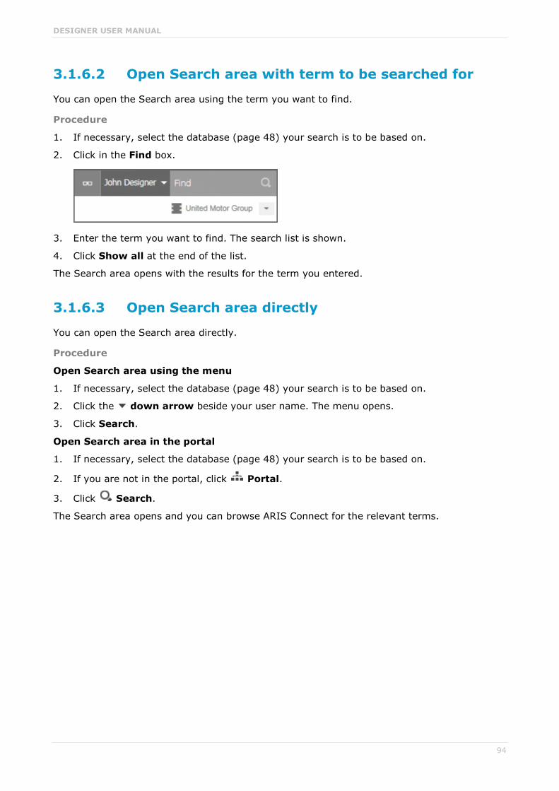
DESIGNER USER MANUAL
94
3.1.6.2 Open Search area with term to be searched for
You can open the Search area using the term you want to find.
Procedure
1. If necessary, select the database (page 48) your search is to be based on.
2. Click in the Find box.
3. Enter the term you want to find. The search list is shown.
4. Click Show all at the end of the list.
The Search area opens with the results for the term you entered.
3.1.6.3 Open Search area directly
You can open the Search area directly.
Procedure
Open Search area using the menu
1. If necessary, select the database (page 48) your search is to be based on.
2. Click the down arrow beside your user name. The menu opens.
3. Click Search.
Open Search area in the portal
1. If necessary, select the database (page 48) your search is to be based on.
2. If you are not in the portal, click Portal.
3. Click Search.
The Search area opens and you can browse ARIS Connect for the relevant terms.

DESIGNER USER MANUAL
95
3.1.6.4 Find using the Search area
You can use the Search area to find items. The Search area offers a wide range of filter options.
Procedure
1. If necessary, select the database (page 48) your search is to be based on.
2. If you are not in the portal, click Portal.
3. Click Search.
4. Enter the term you want to find. The items found will be presented in a list.
5. Click the down arrow that follows the term you entered and select the search context, e.g., Portal or Documents.
The search results are updated according to the search context. If filters are available for the selected context, they are listed in the Filters area.
6. In the Filters area, click the relevant filters and adjust the filter properties as necessary (page 96).
The result of the search will be updated to reflect the search context and filter criteria you specified.

DESIGNER USER MANUAL
96
3.1.6.5 Use search context and filters
You can restrict the result in the Search area (page 95) to the items you want to find by using the search context and filters.
Procedure
1. In the Search area, click the down arrow that follows the term you entered, and select, e.g., Portal, Models, Collaboration, or Documents.
The search result will be restricted to the range you selected. If the search result can be filtered, filter criteria will be listed in the Filters area.
2. Click one or more filter criteria. The selected filter criteria will be listed and the search result updated. If you have selected a filter criterion that you can define more precisely, another area with subordinate filter criteria will be added to the Filters area.
3. Click additional criteria. The selected criteria will be displayed in the Search area and restrict the search result.
a. Selected filter criteria are listed:
b. You can enter properties as the search criterion for certain filter criteria, e.g., the file
name:
You will be offered different input options depending on the property type. A calendar opens so you can select a date:

DESIGNER USER MANUAL
97
4. If necessary, specify the property of the search criterion.
5. To clear a selected filter criterion, click Clear. The filter criterion will be cleared and the search result updated.
6. To see more search criteria, click Show more in the Filters area. The list will be extended.
7. To clear all filter criteria for an area, click Clear subordinate filters.
8. To clear all filters and base your search on other search criteria, click Clear all filters in the Filters area. All previously selected search criteria will be cleared.
The list of results will be updated according to the search context and the selected criteria.
3.1.6.6 Save filter settings as a favorite
In the Search area (page 102), you can save your filter settings. Thus, you can filter the content based on specific filters at any time.
Procedure
1. Select the filter criteria (page 96) to define your filter.
2. Click Save filters as favorites. The dialog opens.
3. Enter a name.
4. Click OK.
The filter settings are saved in the Favorites area. You can filter the content based on these settings (Seite 97) at any time from various devices.
3.1.6.7 Use a favorite in the Search area
In the Search area (page 102), you can open a favorite setting to filter the content based on predefined filter criteria.
Procedure
1. Click Favorites in the Filters bar.
2. Click the favorite setting you want to use as the filter.
The filter criteria of the selected favorite setting are immediately applied and the list of filter results is updated.

DESIGNER USER MANUAL
98
3.1.6.8 Use a favorite in the Favorites area
In the Favorites area (page 103), you can open a favorite setting to filter the content based on predefined filter criteria.
Procedure
1. In the Portal, activate the Favorites tab.
2. Click the down arrow of the Filter selection field.
3. Click the favorite setting of the context caption, e. g., My processes. The content of the selected database is filtered.
If the filter result does not fit on one page, page numbers are displayed behind the Filter selection field.
4. Click the page numbers to display the content of the corresponding pages.
5. Click the name of the item. The item opens.
You have filtered database content based on your filter setting and opened one of your favorites using the Favorites tab.

DESIGNER USER MANUAL
99
3.1.6.9 Clear filters
You can clear filter criteria in more than one way.
Procedure
Clear a selected filter criterion
You can clear a single filter criterion.
Procedure
To the left of the result list, click a selected filter criterion again or click Clear for a filter criterion.
The filter criterion is cleared and the list of filter results updated.
Clear criteria from the main filter area
You can clear all filter criteria from the main filter area. The main filter area is the upper part of the filter bar located to the left of the list of results.
Procedure
Click Show all in the Filter bar.
All filter criteria are cleared and the list of filter results is updated.
Clear filter criteria from the subordinate filter area
You can clear the filter criteria from the subordinate filter area. If you have selected the Models context for filtering, the subordinate filter criteria for models are located in the Filter access bar below the main filter area.
Procedure
Click Clear subordinate filters in the Filter bar.
The filter criteria of the subordinate filter area are removed and the the list of filter results is updated.
Clear all filter criteria
You can clear all filter criteria.
Procedure
Click Clear all filters at the top right.
All filter criteria are cleared and the list of filter results is updated.
You have cleared filter criteria.

DESIGNER USER MANUAL
100
3.1.6.10 Open search result on separate tab
You can open the items found on a separate tab. In this way, the search result remains available, and you can process the items found one after the other.
Procedure
1. Search for an item using the Search area (page 95).
2. Hold down the Ctrl key, and click the name of the relevant item.
The item will open on a separate tab.

DESIGNER USER MANUAL
101
3.1.6.11 Valuable information
This section provides background information to assist you in carrying out the relevant procedures.
3.1.6.11.1 How is the quick search structured?
Quick search consists of a single input box:
A search list is compiled and displayed as soon as you have entered a search term. The first matches are output by category:
The total number of matches is output at the end of the search list.
To access all matches, click Show all. The Search area opens (page 102).

DESIGNER USER MANUAL
102
3.1.6.11.2 How is the Search area structured?
The Search area (page 94) includes a list of all matches.
To the right of the search term you entered, you can select the search context, e.g., Portal or Documents.
To the left of the list, the filter criteria are offered under Filters. If you click the filter criteria, they are listed above the matches and restrict the list of results. Clicking a selected filter criterion again or clicking Remove will clear the criterion.
For certain filter criteria, such as the file name, you can enter properties as the search criterion, e.g., a term that should be present in the name.
If there are too many matches to display all at once, page numbers appear at the end of the list of results. If you click one of these numbers, the matches on that page will be output.

DESIGNER USER MANUAL
103
3.1.6.11.3 How is the Favorites area structured?
The Filter area reflects the saved search context. The search contexts are structured by captions, e.g., Portal or Documents. The saved favorites are grouped under the captions. Thus, you are able to immediately recognize the search contexts of the favorites.
3.1.6.11.4 How can search results be influenced?
If you use quick search (page 93) or the Search area (page 95) to find items, the list of results will be influenced by the selected database (page 48) and the license you are using.
For example, if you are using an ARIS Connect Viewer license, the Models area, from which you can open models for editing in the Model Editor, will not be displayed. This area is displayed to users with the ARIS Connect Designer license. These users are allowed to open models for editing.
DESIGNER USER MANUAL
104
3.1.7 Contribute as a viewer
If you have both the ARIS Connect Viewer and Contribution license privilege, you can change values of specific items (page 110), create new or reuse existing items (page 105), as well as delete items (page 107) in the portal.
Please note that the description is based on the sample configuration supplied with the classic view of ARIS Connect. In your installation other items may have been configured to be editable and the editing options for items may be different.
3.1.7.1 Change values of items
You can change values of items (page 110) in the portal.
Prerequisites You have the ARIS Connect Viewer and Contribution license privileges, or the ARIS
Connect Designer license privilege.
The Workspace database content was published for versionable databases.
You have at least the Write access privilege for the items you want to edit.
Procedure
1. Open ARIS Connect and log in with your user name and password.
2. Click Portal if it is not activated yet.
3. Depending on the view in use, click Groups or Processes.
4. Click Navigation if the navigation bar is not shown.
5. Click Edit > Contribute. The edit mode (page 109) is enabled.
6. Navigate to the group containing the relevant item.
7. Select the item you want to edit.
8. Activate the Overview area if it is not activated yet.
9. Change the relevant attribute. Depending on the attribute, various editing options (page 112) are available.
10. Confirm your changes.
Your changes are saved.
Text formatting is ignored and cannot be assigned. If you are expected to enter numbers, the field is colored red (page 112) if you do not enter a numerical value.

DESIGNER USER MANUAL
105
3.1.7.2 Create or reuse items in a table
In the portal, you can create new or reuse existing items.
The following description refers to items in a table (page 112). It uses the example of an object of the Risk type.
Prerequisites You have the ARIS Connect Viewer and Contribution license privileges, or the ARIS
Connect Designer license privilege.
The Workspace database content was published for versionable databases.
You have at least the Write access privilege for the items you want to edit.
Procedure
1. Open ARIS Connect and log in with your user name and password.
2. Click Portal if it is not activated yet.
3. Depending on the view in use, click Groups or Processes.
4. Click Navigation if the navigation bar is not shown.
5. Click Edit > Contribute. The edit mode (page 109) is enabled.
6. Navigate to the required diagram and select it.
7. Click the object to which you want to assign additional roles. To add objects of the Role type to the Groups table, you can select a risk from the sample configuration supplied.
8. In the Activities area, click the plus sign. The input box opens.
9. Enter the name of the role. If a role with the same name already exists, it is offered to you for selection. In addition, this name is listed with (new item) added to it.
10. To create a new role and assign the risk to it, click the entry with (new item) added to it. To reuse an existing role and assign the risk to it, click the other entry.
11. Click Change. A completion message is displayed.
The new role was created (page 115) and added to the list, or the existing role will be reused. If you selected a role to which the risk was already assigned, no new entry is added to the table.

DESIGNER USER MANUAL
106
3.1.7.3 Create or reuse items in a list
In the portal, you can create new or reuse existing items.
The following description refers to items in a list (page 112). It uses the example of an application system type diagram.
Please note that new items you may have created are added to the diagram. At the same time, a new layout is automatically generated for the diagram. As a consequence, the arrangement of items in the diagram may differ from the original arrangement. If required, a user with the ARIS Connect Designer license privilege can adapt the layout of the diagram in Model Editor.
Prerequisites You have the ARIS Connect Viewer and Contribution license privileges, or the ARIS
Connect Designer license privilege.
The Workspace database content was published for versionable databases.
You have at least the Write access privilege for the items you want to edit.
Procedure
1. Open ARIS Connect and log in with your user name and password.
2. Click Portal if it is not activated yet.
3. Depending on the view in use, click Groups or Processes.
4. Click Navigation if the navigation bar is not shown.
5. Click Edit > Contribute. The edit mode (page 109) is enabled.
6. Navigate to the required diagram and select it. To add objects of the Application system type type to the Subordinate IT systems area, you can select an application system type diagram from the sample configuration supplied, for example.
7. Activate the Overview area if it is not activated yet.
8. Click the Subordinate IT systems edit box. Existing objects are displayed one next to the other and the option Insert item is shown.
9. Enter the name of the required application system type. If an application system type with the same name already exists, it is offered to you for selection. In addition, this name is listed with (new item) added to it.
10. To create a new application system, click the entry with (new item) added to it. To reuse an existing application system type, click the other entry.
11. Enter other names for additional application system types.
12. Click Change. A confirmation prompt is shown listing all new application system types for confirmation.
13. Click OK.
New application system types (page 115) are added to the list, or existing application system types will be reused. Occurrences of new application system types are placed in the diagram window.

DESIGNER USER MANUAL
107
3.1.7.4 Delete items from tables
In the portal, you can delete items from tables.
The following description refers to items in a table (page 112). It uses the example of an object of the Risk type.
Prerequisites You have the ARIS Connect Viewer and Contribution license privileges, or the ARIS
Connect Designer license privilege.
The Workspace database content was published for versionable databases.
You have at least the Delete access privilege for the items you want to delete.
Procedure
1. Open ARIS Connect and log in with your user name and password.
2. Click Portal if it is not activated yet.
3. Depending on the view in use, click Groups or Processes.
4. Click Navigation if the navigation bar is not shown.
5. Click Edit > Contribute. The edit mode (page 109) is enabled.
6. Navigate to the required diagram and select it.
7. Click the object whose associated item you want to delete. To delete objects of the Role type from the Groups table, you can select a risk from the sample configuration supplied.
8. In the Groups area, click Delete for the role from which you want to remove the risk assignment. A confirmation prompt is shown.
9. Click OK to confirm the prompt if you really want to delete the assignment to the role.
The assignment to the role is then deleted. If the assignment was represented as a connection in diagrams, this connection will be deleted from these diagrams. Definitions are retained in the database.

DESIGNER USER MANUAL
108
3.1.7.5 Delete items from lists
In the portal, you can delete items from lists and thus from diagrams.
The following description refers to items in a list (page 112). It uses the example of an application system type diagram.
Prerequisites You have the ARIS Connect Viewer and Contribution license privileges, or the ARIS
Connect Designer license privilege.
The Workspace database content was published for versionable databases.
You have at least the Delete access privilege for the items you want to delete.
Warning
Please note that the deletion of items affects the layout of diagrams. Due to the delete operation, a new layout is automatically generated for the current diagram. As a consequence, the arrangement of items in the diagram may differ from the original arrangement. If required, a user with the ARIS Connect Designer license privilege can adapt the layout of the diagram in Model Editor.
Procedure
1. Open ARIS Connect and log in with your user name and password.
2. Click Portal if it is not activated yet.
3. Depending on the view in use, click Groups or Processes.
4. Click Navigation if the navigation bar is not shown.
5. Click Edit > Contribute. The edit mode (page 109) is enabled.
6. Navigate to the required diagram and select it. To delete objects of the Application system type type from the Subordinate IT systems area, you can select an application system type diagram from the sample configuration supplied, for example.
7. Activate the Overview area if it is not activated yet.
8. Click the edit box in the Subordinate IT systems area. Existing objects are displayed one next to the other with a delete sign (x) added to them.
9. Click the delete sign for the application system types you want to delete from the diagram.
10. Click Change. A confirmation prompt is displayed listing all application system types to be deleted.
11. Click OK.
The application system types are deleted from the list, and also from the application system type diagram together with their connections. Definitions are retained in the database.

DESIGNER USER MANUAL
109
3.1.7.6 Valuable information
This section provides background information to assist you in carrying out the relevant procedures.
3.1.7.6.1 Requirements for Contribution
For a user to be able to work with ARIS Viewer Contribution the following requirements must be met:
The user has the ARIS Connect Viewer and Contribution license privileges.
The Workspace database content was published for versionable databases.
The user has at least the Write access privilege for the group content of the database to be edited. Deleting items requires the Delete access privilege.
The administrator has activated the classic view, default view, or a view derived from these views.
3.1.7.6.2 How to identify whether the edit mode is active
The edit mode is displayed in the header. If it is not active, only the symbol and Edit are displayed:
Clicking Edit > Contribute enables the edit mode.
If the edit mode is active, this is shown in the header:
Clicking Exit edit mode disables the edit mode.
The availability of various edit boxes (page 112) is another clear indication that the edit mode is active.

DESIGNER USER MANUAL
110
3.1.7.6.3 Which items are you allowed to change using the Contribution privilege?
If you have both the ARIS Connect Viewer and Contribution license privilege, you are able to change items and values for the following predefined items in the portal. 'Predefined' means that these items and their values were configured to be editable in the program by default.
This means that not all items of the following model and object types can be changed. Only those can be changed that were designed to be editable by the underlying concept and were set up accordingly by the configuration.
Please note that this is a sample configuration, which means that other items may have been configured to be editable in your installation.
MODEL TYPES
Application system type diagram
BPMN collaboration diagram (BPMN 2.0)
BPMN process diagram (BPMN 2.0)
Business controls diagram
Enterprise BPMN collaboration diagram
Enterprise BPMN process diagram
EPC
EPC (material flow)
EPC (column display)
EPC (table display)
EPC (horizontal table display)
EPC (row display)
Function allocation diagram
Organizational chart
Process schedule
Risk diagram
KPI allocation diagram
OBJECT TYPES
Application system
Application system class
Application system type
Cluster/Data model
Entity type
Event
Technical term

DESIGNER USER MANUAL
111
Function
Information carrier
KPI instance
Class
Lane
List
Message
Organizational unit
Participant
Person
Risk
Risk category
Role
Location
Position
System organizational unit
System organizational unit type
Test definition
3.1.7.6.4 Which attributes are you able to edit?
ARIS Viewer Contribution enables you to edit attributes (page 112) that are based on the following base types:
Boolean
Value
Floating point number domain
Integer domain
Floating point number
Integer
Date
One-liner
Multi-line text
Link/File
Text formatting is ignored and cannot be assigned. If you are expected to enter numbers, the field is colored red (page 112) if you do not enter a numerical value.
Please note that combined attributes and Binary Large Object (BLOB) attributes are not supported.
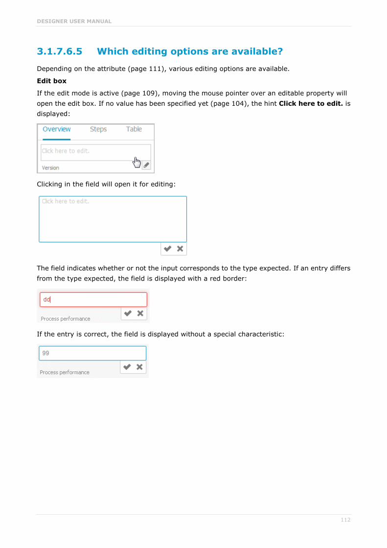
DESIGNER USER MANUAL
112
3.1.7.6.5 Which editing options are available?
Depending on the attribute (page 111), various editing options are available.
Edit box
If the edit mode is active (page 109), moving the mouse pointer over an editable property will open the edit box. If no value has been specified yet (page 104), the hint Click here to edit. is displayed:
Clicking in the field will open it for editing:
The field indicates whether or not the input corresponds to the type expected. If an entry differs from the type expected, the field is displayed with a red border:
If the entry is correct, the field is displayed without a special characteristic:

DESIGNER USER MANUAL
113
Select user(s)
If you want to select a user, you will be offered a list of the users logged in to the system for you to select in a dialog, e.g., for the Responsible attribute:
Date input
You can enter dates using the calendar. It opens when you click in the edit box:

DESIGNER USER MANUAL
114
Drop-down list box
For attributes that require the entry of specific values or of Boolean attributes, you can select the appropriate entry, e.g., for the Model status attribute:
Clicking in the field will offer possible values for selection:
CREATE AND REUSE OBJECTS
Table
Existing objects are listed in a table. Additional information is displayed in the individual rows:
You can add individual objects to the table (page 105) or remove objects from the table (page 107).
List
Existing objects are displayed in a list:
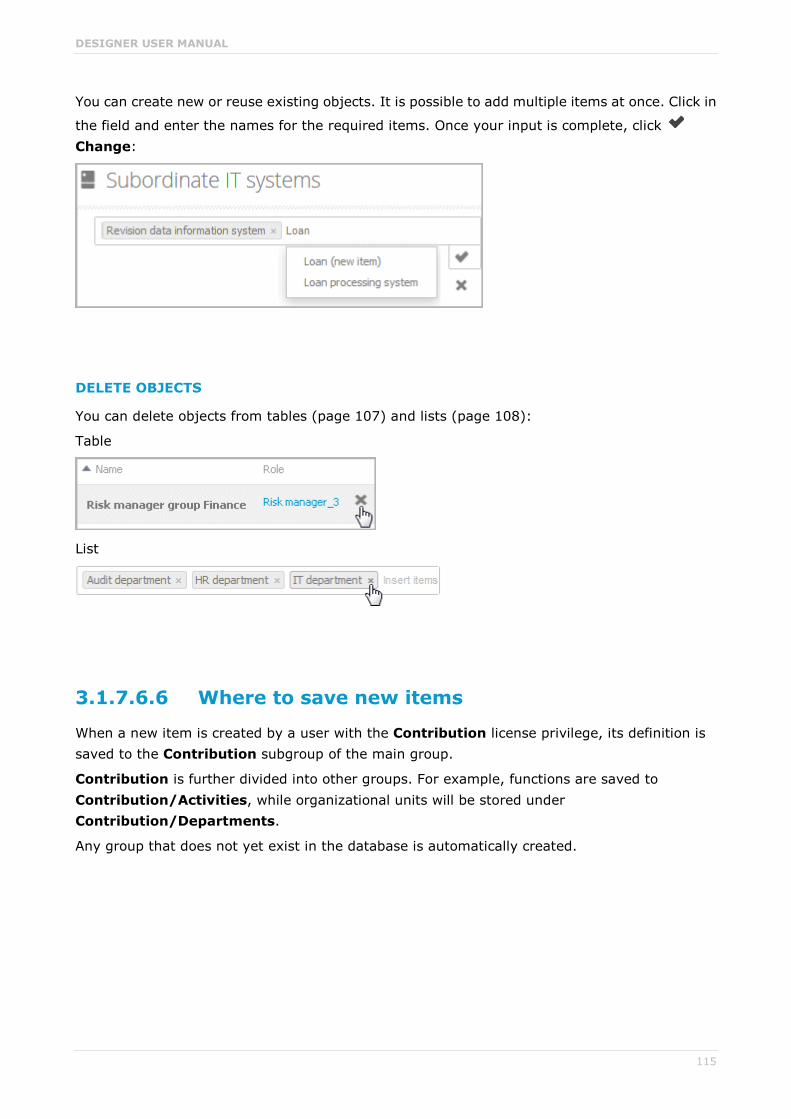
DESIGNER USER MANUAL
115
You can create new or reuse existing objects. It is possible to add multiple items at once. Click in
the field and enter the names for the required items. Once your input is complete, click Change:
DELETE OBJECTS
You can delete objects from tables (page 107) and lists (page 108):
Table
List
3.1.7.6.6 Where to save new items
When a new item is created by a user with the Contribution license privilege, its definition is saved to the Contribution subgroup of the main group.
Contribution is further divided into other groups. For example, functions are saved to Contribution/Activities, while organizational units will be stored under Contribution/Departments.
Any group that does not yet exist in the database is automatically created.

DESIGNER USER MANUAL
116
3.1.8 Manage SAP Solutions
Process-Driven Management for SAP® Solutions is available, if you have selected this topic in the Perspective Wizard.
You can refine and evaluate your business processes in ARIS. This enables you to optimize your business processes.
Depending on the SAP Solution Manager® version in use, you need to configure the system differently (see Using SAP Solution Manager 7.2 and Using SAP Solution Manager 7.1. All other procedures are version-independent.
ARIS video tutorial Process-Driven SAP Management Two-Minute Explainer (http://www.softwareag.com/corporate/rc/rc_perma.asp?id=tcm:16-97174)
Connectivity for SAP Solutions in ARIS, 4 minutes (http://www.softwareag.com/corporate/rc/rc_perma.asp?id=tcm:16-116500)
3.1.8.1 Run SAP® transaction
Run transactions in the connected SAP system.
Prerequisite You have at least the ARIS Connect Viewer license privilege.
You are using Process-driven Management for SAP.
Your administrator has configured the portal for the use of SAP content.
Procedure
1. Open ARIS Connect and log in with your user name and password.
2. Click Portal if it is not activated yet.
3. Depending on the view in use, click Groups or Processes.
4. Click Navigation if the navigation bar is not shown.
5. Navigate to the relevant model ot the EPC type, where transactions are available.
6. Click Transactions. You can start the transaction automatically via the default server in each row displaying a transaction code. Click the arrow head to display all registered SAP Servers. The default server selected is indicated by a check mark.
7. Run the transaction. The SAP logon dialog opens.
8. Enter the number of the SAP client and the user name, and click OK. Depending on your browser settings, the Run SAP transaction dialog opens.
9. Enter the password and click Log on.
The transaction is run in the current language. The logon remains active until you log out of the portal, enter different logon data, or close the SAP system. To delete the current SAP logon data, click the arrow head and then Reset logon data. For the next transaction start you need to log on to the SAP system again.

DESIGNER USER MANUAL
117
3.1.8.2 Reset SAP® logon data
Change the logon information for running transactions.
Prerequisite You have at least the ARIS Connect Viewer license privilege.
You are using Process-driven Management for SAP.
This function has been configured in the portal.
Procedure
1. Open ARIS Connect and log in with your user name and password.
2. Click Portal if it is not activated yet.
3. Depending on the view in use, click Groups or Processes.
4. Click Navigation if the navigation bar is not shown.
5. Open the relevant model.
6. Click Transactions.
7. In the last column of a transaction code, click the arrow head and then Reset logon data.
For the next transaction start (page 116) you need to log on to the SAP system again.
3.1.8.3 Download SAP® documents
You can download SAP documents that are associated with SAP transactions.
Prerequisite You have at least the ARIS Connect Viewer license privilege.
You are using Process-driven Management for SAP.
Documents are available.
This function has been configured in the portal.
Procedure
1. Open ARIS Connect and log in with your user name and password.
2. Click Portal if it is not activated yet.
3. Depending on the view in use, click Groups or Processes.
4. Click Navigation if the navigation bar is not shown.
5. Open the relevant model.
6. Click Transactions.
7. Click the relevant transaction code. The fact sheet opens.
8. Next to the relevant document, click Download document.
The document is downloaded.

DESIGNER USER MANUAL
118
3.1.8.4 Configure ARIS Online Guide
If the ARIS Online Guide is used for making documents that were created in the SAP ® system specially for your business processes available across the company, configure your custom settings to call the ARIS Online Guide.
Prerequisite
ARIS and the SAP® system have been configured for using the ARIS Online Guide.
Procedure
1. Log on to the SAP system.
2. Start the /n/IDS/AOG_USER transaction. The ARIS Online Guide - User-specific settings dialog opens.
3. Enable the Use ARIS Online Guide check box.
4. Select the Connect option to display the ARIS Online Guide in the portal in ARIS Connect.
5. If you also want to use the F1 help from the SAP system in addition to the ARIS Online Guide, enable the Also show default help check box.
6. Enter the required connection data for ARIS Server and tenant on which the database was published as a portal. You administrator might already have specified default entries that you do not need to edit.
Base URL for Connect
URL for the relevant ARIS Server:
http://<server name>
Tenant
Tenant that manages the database published as a portal.
7. Save your changes.
The settings have been applied.
If you changed the default values set by your administrator and want to restore them, click Restore defaults.

DESIGNER USER MANUAL
119
3.1.8.5 Start ARIS Online Guide
If your administrator has provided ARIS Online Guide via ARIS Connect, you can open the relevant portal pages from SAP screens using the F1 key. All transactions are shown there in relation to the process. Details are summarized in corresponding fact sheets.
Prerequisites This function has been configured in the portal.
You have configured the help call (page 118).
Procedure
Press the F1 key in the open screen. The corresponding portal page opens (link syntax: http://<server name:port>/?tcode=<transaction code>#<tenant>/onlineguide)
All information pertaining to this transaction is available on the open page.

DESIGNER USER MANUAL
120
3.1.9 Use RACI matrix
Using the RACI matrix you can represent and analyze responsibilities that exist within a process (page 122). RACI is short for Responsible, Accountable, Supportive, Consulted, and Informed.
The matrix shows which organizational unit participates in activities of a process and in what manner:
Responsible indicates who assumes execution responsibility. It shows who is responsible for performing an activity and who actually performs it, but also who assumes the disciplinary responsibility. Execution responsibility must be assigned to at least one role, although others (see Supportive) can be delegated to assist in the work required.
Accountable identifies the person ultimately answerable for the correct and thorough completion of a task. Thus, 'Accountable' may be the one in charge of managing the costs, i.e., the one who assumes project budget responsibility. The decides on and accepts connections are evaluated in order to mark this responsibility.
Supportive relates to the person supporting the person responsible (see 'Responsible') in performing the activity.
Consulted shows who has a consulting role. This organizational unit - typically a group of subject matter experts - is asked for advice prior to a final decision being made or a final action being taken.
Informed specifies who must be informed. It indicates who is kept up to date on the progress or completion of a task.
3.1.9.1 Create process model for RACI matrix
You can model processes that can be evaluated as a RACI matrix.
Prerequisite
You have the ARIS Connect Designer privilege.
Procedure
1. Create a process model (page 122).
2. Use objects (page 122) and connections that can be evaluated by the RACI matrix.
3. Save the process.
You have modeled a process for which the relevant responsibilities can be represented using a RACI matrix (page 121).

DESIGNER USER MANUAL
121
3.1.9.2 Display RACI matrix
A RACI matrix can display the activities of a process and the associated organizational responsibilities.
Procedure
1. Activate the portal if it is not activated yet.
2. If your administrator has published multiple databases, select the required database by
clicking the current database name next to the database symbol and then clicking the name of the relevant database.
3. Click Groups.
4. Show the Navigation bar if it is not visible yet.
5. In the Navigation, open the group in which the required process (page 122) is stored.
6. Click the name of the process for which you want to display the RACI matrix. The entry RACI is shown.
7. Click RACI.
The RACI matrix is displayed for the process model you have selected. The functions of the process are arranged in rows, the organizational elements are arranged in columns. In the portal, process participations are displayed by default as a RACI matrix in classic view (page 14) and default view. You can configure the representation as RASCI matrix. Please contact your local Software AG sales organization (http://softwareag.com).
You can use the RA(S)CI - Output organizational participations in processes (page 152) report to output the RACI matrix in Microsoft® Excel format from an open process model (page 212). By default, this report does not return any Supportive information. To output this information, your script administrator must set the g_bRASCI variable to true.

DESIGNER USER MANUAL
122
3.1.9.3 Valuable information
This section provides background information to assist you in carrying out the relevant procedures.
3.1.9.3.1 Which diagrams can be used for a RACI matrix?
A RACI matrix can be based on the following diagramms:
EPC (API name MT_EEPC)
EPC (column display) (API name MT_EEPC_COLUMN)
EPC (material flow) (API name MT_EEPC_MAT)
EPC (row display) (API name MT_EEPC_ROW)
EPC (table display) (API name MT_EEPC_TAB)
EPC (horizontal table display) (API name MT_EEPC_TAB_HORIZONTAL)
BPMN collaboration diagram (BPMN 2.0) - (API name MT_BPMN_COLLABORATION_DIAGRAM)
BPMN process diagram (BPMN 2.0) (API name MT_BPMN_PROCESS_DIAGRAM)
Enterprise BPMN collaboration diagram (API name MT_ENTERPRISE_BPMN_COLLABORATION)
Enterprise BPMN process diagram (API name MT_ENTERPRISE_BPMN_PROCESS)
Function allocation diagram (API name MT_FUNC_ALLOC_DGM). This model must be assigned to a function.
Value-added chain diagram (API name MT_VAL_ADD_CHN_DGM)
3.1.9.3.2 Which objects can be used for a RACI matrix?
The following objects are evaluated by a RACI matrix:
Function (API name OT_FUNC)
Group (API name OT_GRP)
Organizational unit (API name OT_ORG_UNIT)
Organizational unit type (API name OT_ORG_UNIT_TYPE)
Person (API name OT_PERS)
Role (API name OT_PERS_TYPE)
Position (API name OT_POS)

DESIGNER USER MANUAL
123
3.1.9.3.3 Which connections can be used for a RACI matrix?
The following connections between organizational elements and functions are evaluated by the RACI matrix:
RESPONSIBLE (R)
carries out (API name: CT_EXEC_1)
carries out (API name: CT_EXEC_2)
ACCOUNTABLE (A)
decides on (API name: CT_DECD_ON)
decides on (API name: CT_DECID_ON)
accepts (API name: CT_AGREES)
CONSULTED (C)
is technically responsible for (API name CT_IS_TECH_RESP_1)
is technically responsible for (API name CT_IS_TECH_RESP_3)
has consulting role in (API name CT_HAS_CONSLT_ROLE_IN_1)
has consulting role in (API name CT_HAS_CONSLT_ROLE_IN_2)
INFORMED (I)
must be informed about (API name: CT_MUST_BE_INFO_ABT_1)
must be informed about (API name: CT_MUST_BE_INFO_ABT_2)
must be informed on cancellation (API name: CT_MUST_BE_INFO_ON_CNC_1)
must be informed on cancellation (API name: CT_MUST_BE_INFO_ON_CNC_2)
If RA(S)CI was set, the following connections are additionally available:
SUPPORTIVE (S)
contributes to (API name CT_CONTR_TO_1)
contributes to (API name CT_CONTR_TO_2)

DESIGNER USER MANUAL
124
3.1.10 Use Mini workflows
3.1.10.1 Edit models
You can edit models in ARIS Connect.
Prerequisite You have the ARIS Connect Designer privilege.
When using Microsoft® Internet Explorer version 8, the compatibility mode must be disabled.
Procedure
1. Open ARIS Connect and log in with your user name and password.
2. Click Portal if it is not activated yet.
3. Depending on the view in use, click Groups or Processes.
4. Click Navigation if the navigation bar is not shown.
5. Click the name of the model you want to edit.
6. Click Edit > Edit model. The model opens in the Model Editor on an individual tab.
7. Make the required changes.
8. Click Save.
Your changes are saved in the model.
All users can select the language to be used for the notification in their profile in ARIS Connect.
This workflow is a part of ARIS Connect. It can be customized, if required. For example, you can change e-mail texts, add notifications, make changes to dialogs, etc. The integration of complex workflows (standard RCM, change management, etc.) requires the ARIS Design Server license or ARIS Connect Server extension pack: Process Governance.
3.1.10.2 Share model
You can share models with other users.
Prerequisite You have at least the ARIS Connect Viewer license privilege.
When using Microsoft® Internet Explorer version 8, the compatibility mode must be disabled.
Procedure
1. Open ARIS Connect and log in with your user name and password.
2. Click Portal if it is not activated yet.
3. Depending on the view in use, click Groups or Processes.
4. Click Navigation if the navigation bar is not shown.
5. Click the model you want to send to another user.
DESIGNER USER MANUAL
125
6. Click Share model. The dialog opens.
7. Select the user you want to share the model with.
8. Enable Send copy to me to receive a copy of the message, if required.
9. You can also enter a subject and a comment.
10. Click Send.
The selected user receives an e-mail containing the information you entered and a link to the corresponding model.
All users can select the language to be used for the notification in their profile in ARIS Connect.
This workflow is a part of ARIS Connect. It can be customized, if required. For example, you can change e-mail texts, add notifications, make changes to dialogs, etc. The integration of complex workflows (standard RCM, change management, etc.) requires the ARIS Design Server license or ARIS Connect Server extension pack: Process Governance.
3.1.10.3 Submit change request
You can send change requests for models to the person responsible.
Prerequisites You have at least the ARIS Connect Viewer license privilege.
The Person responsible model attribute must be specified for the relevant model with a user name that exists in the user management.
When using Microsoft® Internet Explorer version 8, the compatibility mode must be disabled.
Procedure
1. Open ARIS Connect and log in with your user name and password.
2. Click Portal if it is not activated yet.
3. Depending on the view in use, click Groups or Processes.
4. Click Navigation if the navigation bar is not shown.
5. Click the model for which you want to submit a change request.
6. Click Submit change request. The dialog opens.
7. Enter a title and a description for your request.
8. Select the priority with which the request is to be handled.
9. Add any relevant documents, graphics, etc. that could be used as a basis for editing.
10. Click Send. A completion message is displayed.
11. Click OK.
The person responsible receives the change request by e-mail with a link to the relevant model and a link to edit the associated task in ARIS Process Board.
Once the person responsible has processed the request, the applicant receives a message by e-mail.

DESIGNER USER MANUAL
126
As soon as the first change request is made, the ARIS Connect Governance Inbox database is automatically created in ARIS. It contains a Requirements inbox for each person responsible with a model of the Requirements tree type. An object of the Requirement type is created for each change request. As the process continues, the realization status of the object is automatically changed depending on which status the person responsible has selected (Approve, Reject). This enables all change requests to be monitored in the ARIS Connect Governance Inbox database.
All users can select the language to be used for the notification in their profile in ARIS Connect.
This workflow is a part of ARIS Connect. It can be customized, if required. For example, you can change e-mail texts, add notifications, make changes to dialogs, etc. The integration of complex workflows (standard RCM, change management, etc.) requires the ARIS Design Server license or ARIS Connect Server extension pack: Process Governance.
3.1.10.4 Ask for model approval
Ask the person in charge to approve the models you changed so that the changed models can be made available to all users.
Prerequisite You have at least the ARIS Connect Viewer license privilege.
When using Microsoft® Internet Explorer version 8, the compatibility mode must be disabled.
Procedure
1. Open ARIS Connect and log in with your user name and password.
2. Click Portal if it is not activated yet.
3. Depending on the view in use, click Groups or Processes.
4. Click Navigation if the navigation bar is not shown.
5. Click the name of the model you want to edit.
6. Click Edit > Edit model. The model opens in the Model Editor on an individual tab.
7. Make the required changes.
8. Click Collaboration if it is not activated yet.
9. Click Request approval. The Confirmation dialog opens for you to confirm that the model changes are to be saved and the model is to be reopened read-only.
10. Click OK. The model reopens read-only and the Request approval dialog is displayed.
11. If required, select a person in charge to approve the model if the Person responsible attribute has not been specified at the model.
12. Enter a comment to explain the approval request.
13. Click Send. A completion message is displayed.
14. Click OK.
DESIGNER USER MANUAL
127
The person responsible receives an e-mail with the relevant information and a link to the associated task in ARIS Process Board. If the person responsible approves the changes, the model is automatically published and the current version is provided.
Until then, only you and other modelers can view your changes.
All users can select the language to be used for the notification in their profile in ARIS Connect.
This workflow is a part of ARIS Connect. It can be customized, if required. For example, you can change e-mail texts, add notifications, make changes to dialogs, etc. The integration of complex workflows (standard RCM, change management, etc.) requires the ARIS Design Server license or ARIS Connect Server extension pack: Process Governance.
3.1.10.5 Request feedback on processes
You can request feedback on processes from other users.
Prerequisite You have at least the ARIS Connect Viewer license privilege.
When using Microsoft® Internet Explorer version 8, the compatibility mode must be disabled.
Procedure
1. Open ARIS Connect and log in with your user name and password.
2. Click Portal if it is not activated yet.
3. Depending on the view in use, click Groups or Processes.
4. Click Navigation if the navigation bar is not shown.
5. Click the model for which you want feedback.
6. Click Comment if the Comment bar is not open yet.
7. Enter your comment in the box provided.
8. Click Tag.
9. Enter the words to be used as keywords (page 201) in the tag input box, e.g., BPM. Alternatively, select an existing tag from the list of tags. It is displayed as soon as you enter a letter that is part of an existing tag. Press the Enter key after each keyword.
10. Click Link.
11. Insert a link to a Web site that contains more detailed information.
12. Click Add link. The link is checked and added.
13. Click File. The Select document dialog is displayed.
14. Click Upload new document to upload one of your own documents. The dialog opens.
15. Select the file you want to upload and enter the relevant additional information.
16. Click Upload.
17. Enable the check box of the document you want to add to your post.
18. Click OK.
DESIGNER USER MANUAL
128
The comment is displayed below the process and can be commented on by other users.
All users can select the language to be used for the notification in their profile in ARIS Connect.
This workflow is a part of ARIS Connect. It can be customized, if required. For example, you can change e-mail texts, add notifications, make changes to dialogs, etc. The integration of complex workflows (standard RCM, change management, etc.) requires the ARIS Design Server license or ARIS Connect Server extension pack: Process Governance.
3.1.10.6 Inform owner of change
You can inform the model owner of model changes you have made in the portal (page 104). The process owner is automatically determined by the attribute Person responsible.
Prerequisite You have the ARIS Connect Viewer and Contribution license privileges, or the ARIS
Connect Designer license privilege.
When using Microsoft® Internet Explorer version 8, the compatibility mode must be disabled.
Procedure
1. Open ARIS Connect and log in with your user name and password.
2. Click Portal if it is not activated yet.
3. Depending on the view in use, click Groups or Processes.
4. Click Navigation if the navigation bar is not shown.
5. Navigate to the items and change the relevant attributes (page 104). Depending on the attributes, various editing options (page 112) are available.
6. Click Inform owner of change. The Inform of change dialog opens.
7. Insert a change description
8. Click Submit. The Information dialog opens.
9. Enable the Do not show this message again check box if you do not want to be informed again by the dialog when executing the mini workflow more than once during the current session.
10. Click OK.
The process owner receives an e-mail containing the information you entered. If he submits the human task, you will be informed via e-mail.
This workflow is a part of ARIS Connect. It can be customized, if required. For example, you can change e-mail texts, add notifications, make changes to dialogs, etc. The integration of complex workflows (standard RCM, change management, etc.) requires the ARIS Design Server license or ARIS Connect Server extension pack: Process Governance.

DESIGNER USER MANUAL
129
3.1.11 Use dashboards
Based on a ARIS Aware (page 154) license, you can create and display predefined dashboards that are delivered by default or self-provided dashboards.
3.1.11.1 Open a dashboard in ARIS Connect
You can open a dashboard available in ARIS Connect. The dashboard is displayed in view mode of the dashboard editor.
The dashboards and the relevant data feeds are provided in the ARIS Connect Repository ( ).
Prerequisite You have the View permission for the dashboard. See Manage dashboard permissions for
details.
You have the View permission for the assigned data feeds. See Manage data feed permissions for detail.
Procedure
1. Start ARIS Connect.
2. Activate the Repository.
3. Activate the Dashboard & Data feeds tab.
4. Click Dashboards.
5. To open a dashboard click the relevant dashboard name.
The dashboard selected is opened in view mode of the dashboard editor.
In edit mode you can edit the dashboard currently opened, provided you have the Dashboard
administrator function privilege. Click the Edit dashboard icon in the main menu.
3.1.11.2 Create a dashboard in ARIS Connect
ARIS Connect enables you to create your own dashboards.
By default, dashboards and the relevant data feeds are provided in the ARIS Connect Repository ( ).
Prerequisite
You have the Dashboard administrator function privilege.
Procedure
1. Start ARIS Connect.
2. Activate the Repository.
3. Activate the Dashboard & Data feeds tab.
4. Click Dashboards.

DESIGNER USER MANUAL
130
5. Click New.
The dashboard editor is opened in edit mode.
6. Configure and save your dashboard by using the dashboard editor.
7. Click Refresh.
Your dashboard is created and available in the Dashboards list in the ARIS Connect Repository ( ).
3.1.11.3 Open a data feed in ARIS Connect
You can open a data feed available in ARIS Connect. The data feed is opened in the data feed editor.
The dashboards available and the relevant data feeds are provided in the ARIS Connect Repository ( ).
Prerequisite
You have the Dashboard administrator function privilege.
Procedure
1. Start ARIS Connect.
2. Activate the Repository.
3. Activate the Dashboard & Data feeds tab.
4. Click Data feeds.
5. To open a data feed click the relevant data feed name.
The data feed selected is opened in the data feed editor.
By using the data feed editor you can edit the data feed currently opened, provided you have the Dashboard administrator function privilege.

DESIGNER USER MANUAL
131
3.1.11.4 Create a data feed in ARIS Connect
ARIS Connect enables you to create your own data feeds.
By default, dashboards available and the relevant data feeds are provided in the ARIS Connect Repository ( ).
Prerequisite
You have the Dashboard administrator function privilege.
Procedure
1. Start ARIS Connect.
2. Activate the Repository.
3. Activate the Dashboard & Data feeds tab.
4. Click Data feeds.
5. Click New.
The data feed editor is opened.
6. Configure and save your data feeds by using the data feed editor.
7. Click Refresh.
Your data feed is created and available in the Data feeds list in the ARIS Connect
Repository ( ).

DESIGNER USER MANUAL
132
3.1.11.5 Show dashboards
You can show dashboards for various items. The following example is based on predefined dashboards by default that are contained in the supplied United Motor Group database and the Classic view (page 11).
Prerequisite
Dashboards are configured for the items selected.
Procedure
1. In the Portal, select (page 48) the United Motor Group database.
2. Click Groups. The Group tree opens.
3. Click Processes > 2.1 Process architecture > Enterprise process map. The Overview fact sheet of the Enterprise process map model opens and shows the CoE - Local Maturity (page 159) dashboard.
4. Click 2.1.1 Core processes > 2.1.1.1 Customer services > 2.1.1.1.1 Customer
services process > Customer services process. The Overview fact sheet of the Enterprise process map model opens and shows the CoE - Local Maturity (page 159) dashboard.
5. Click the Dashboards fact sheet. The model's dashboards are shown. You can switch between the Process Change Management (page 162) and the CoE - Local Maturity (page 159) dashboards.
You have shown different dashboards by default.

DESIGNER USER MANUAL
133
3.1.12 Valuable information
This section provides background information to assist you in carrying out the relevant procedures.
3.1.12.1 In which order are object occurrences displayed?
You can display where occurrences of an object are used and select the required occurrence using the navigation controls.
The navigation controls include arrows and a drop-down list:
If you click an arrow, the next occurrence is selected. The order of the occurrences depends on the vertical position of the objects in the model. The occurrence at the top most position is occurrence number 1.
The first number in the drop-down list refers to the occurrence currently selected, the second number represents the total amount of occurrences in a model.
Using the drop-down list, you can directly select a specific object occurrence:
3.1.12.2 What is the portal view?
The portal shows specific information for each user. Different views display information in different ways. By default, ARIS comes with two different views. The classic view (page 11) and the default view. These views are defined in configuration sets, which cannot be changed. However, administrators can define multiple modified modification sets, based on these templates.
DESIGNER USER MANUAL
134
3.1.12.3 What is the structure of the classic view?
If the administrator provides at least one database, this view shows all content relevant to you in a clear structure:
Home (page 13)
Groups (page 14)
Glossary (page 26)
If your administrator has published multiple databases, these are available for selection
. You can switch between the published databases as required.
You only see information in the portal that is relevant to you. This is controlled in user management by administrators.
You can activate role filters (page 62) to further restrict this content. Role filters are available only if roles are assigned (page 61) to your user in models and the portal has been configured for the use of role filters.
Overview
The Overview gives you access to some tabs that allow you to start working with ARIS Connect rapidly.
Start
Find people
Activates Collaboration where you find people (page 190) you want to discuss with, for example.
Start discussion
Activates Collaboration where you can start a new discussion (page 190).
Process Board
Opens ARIS Process Board, where you can edit tasks that are assigned to you.
Navigation
Enables you to browse the ARIS Connect content for models and objects.
Show profile
Opens your profile page. You can edit your data or add an image.
Search
Opens the Search (page 102) area where you can search for ARIS Connect content. You can use filters, for example, to display just the model and objects, UML content, or Collaboration entries.
Recent changes
Shows all links to models that were changed recently.

DESIGNER USER MANUAL
135
My content
Shows the current activities you are following in Collaboration (page 191) or in the portal (page 59).
Favorites
Provides direct access to saved filter criteria (Seite 56) of the Favorites area of the search and to models a user selected as a favorite element.
Contacts
Lists your contacts.
My activities
Shows the current activities you are following in Collaboration or in the portal (page 191).

DESIGNER USER MANUAL
136
3.1.12.4 What is the structure of the default view?
If you click Portal, you can view all information relevant to you.
If the administrator provides at least one database, this view shows all content relevant to you in a clear structure:
Processes (page 30)
Organization (page 41)
IT systems (page 42)
Glossary (page 45)
If your administrator has published multiple databases, these are available for selection
. You can switch between the published databases as required.
You only see information in the portal that is relevant to you. This is controlled in user management by administrators.
You can activate role filters (page 62) to further restrict this content. Role filters are available only if roles are assigned (page 61) to your user in models and the portal has been configured for the use of role filters.
Important for me
Displays processes in which the user logged in or their group is modeled, as well as application systems for which the user or user group is responsible. Processes are models of the EPC type (event-driven process chain).
My activities
Shows the current activities you are following in Collaboration or in the portal (page 191).

DESIGNER USER MANUAL
137
3.1.12.5 When can UML content be displayed?
You can display UML content in ARIS Connect under the following conditions:
You use the classic configuration set.
The database with UML content you are using has been assigned a filter that allows UML content. This may be the Entire method filter or a filter you have defined in which all UML elements are available.
The database has been published by an administrator. It is therefore available in the portal.
You have logged in as a user with the UML Viewer function privilege.
3.1.12.6 Where is UML content displayed?
UML content is displayed in the same way as other ARIS content. You can use the groups (page 14) to navigate in the database.
As soon as you select UML content to be displayed, specific UML characteristics are taken into account.
Thus, UML namespace hierarchies are also displayed together with the group path.
If you select a UML element, you can display its typical UML-specific properties such as stereotypes and tagged values.
If you select a diagram, you can of course display it graphically.
The search also finds UML content.
3.1.12.7 What is the context for executable processes?
The execution context determines from which items (database, group, model/object type, document), in which applications (e.g., ARIS Connect), and by which users a governance process can be started. The context must be defined in ARIS before generating the executable process. After this, the context can no longer be changed for the generated process version. If no execution context is defined, the governance process can be started for all items (Without context option). The defined execution context is displayed in process administration.

DESIGNER USER MANUAL
138
3.1.12.8 What are role filters?
You only see information in the portal that is relevant to you. This is controlled in user management by administrators.
You can activate role filters (page 62) to further restrict this content. Role filters are available only if roles are assigned (page 61) to your user in models and the portal has been configured for the use of role filters.
WHAT INFORMATION IS FILTERED BY A ROLE FILTER?
When you open a diagram, all information is displayed unfiltered. You can also navigate using assignments. If you view processes step by step (page 50), all steps are displayed. The detailed information about the satellites is filtered according to the selected role.
Tables, fact sheets, and RACI matrices contain only role-specific information. You only access filtered information via the search and the navigation.
If you click Off, the role filter is deactivated and you see your entire content again.

DESIGNER USER MANUAL
139
3.1.12.9 What is ARIS Viewer Contribution?
If you have both the ARIS Connect Viewer and Contribution license privilege, you are able to change items and values for the following predefined items in the portal. 'Predefined' means that these items and their values were configured to be editable in the program by default.
This means that not all items of the following model and object types can be changed. Only those can be changed that were designed to be editable by the underlying concept and were set up accordingly by the configuration.
Please note that this is a sample configuration, which means that other items may have been configured to be editable in your installation.
MODEL TYPES
Application system type diagram
BPMN collaboration diagram (BPMN 2.0)
BPMN process diagram (BPMN 2.0)
Business controls diagram
Enterprise BPMN collaboration diagram
Enterprise BPMN process diagram
EPC
EPC (material flow)
EPC (column display)
EPC (table display)
EPC (horizontal table display)
EPC (row display)
Function allocation diagram
Organizational chart
Process schedule
Risk diagram
KPI allocation diagram
OBJECT TYPES
Application system
Application system class
Application system type
Cluster/Data model
Entity type
Event
Technical term
DESIGNER USER MANUAL
140
Function
Information carrier
KPI instance
Class
Lane
List
Message
Organizational unit
Participant
Person
Risk
Risk category
Role
Location
Position
System organizational unit
System organizational unit type
Test definition
ATTRIBUTES
ARIS Viewer Contribution enables you to edit attributes (page 112) that are based on the following base types:
Boolean
Value
Floating point number domain
Integer domain
Floating point number
Integer
Date
One-liner
Multi-line text
Link/File
Text formatting is ignored and cannot be assigned. If you are expected to enter numbers, the field is colored red (page 112) if you do not enter a numerical value.
Please note that combined attributes and Binary Large Object (BLOB) attributes are not supported.
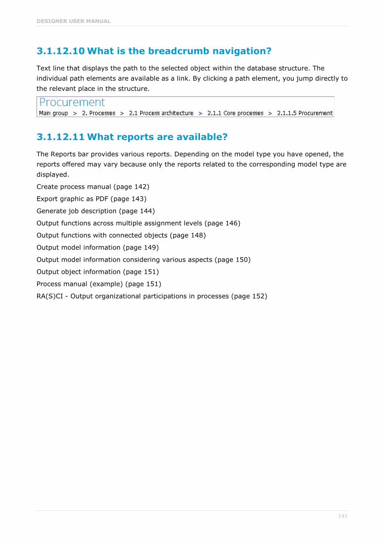
DESIGNER USER MANUAL
141
3.1.12.10 What is the breadcrumb navigation?
Text line that displays the path to the selected object within the database structure. The individual path elements are available as a link. By clicking a path element, you jump directly to the relevant place in the structure.
3.1.12.11 What reports are available?
The Reports bar provides various reports. Depending on the model type you have opened, the reports offered may vary because only the reports related to the corresponding model type are displayed.
Create process manual (page 142)
Export graphic as PDF (page 143)
Generate job description (page 144)
Output functions across multiple assignment levels (page 146)
Output functions with connected objects (page 148)
Output model information (page 149)
Output model information considering various aspects (page 150)
Output object information (page 151)
Process manual (example) (page 151)
RA(S)CI - Output organizational participations in processes (page 152)

DESIGNER USER MANUAL
142
3.1.12.11.1 Create process manual
USE
This report outputs all data from the selected processes up to the selected assignment level.
CONTEXT
Models of type:
BPMN process diagram (BPMN 2.0)
BPMN process diagram (BPMN 1.x)
E-Business scenario diagram
EPC
EPC (material flow)
EPC (column display)
EPC (horizontal table display)
EPC (table display)
EPC (row display)
Industrial process
Office process
Process schedule
UML Activity diagram
PCD
PCD (material flow)
Value-added chain diagram
OUTPUT FORMAT
DOC
DOCX
ODT
RTF

DESIGNER USER MANUAL
143
3.1.12.11.2 Export graphic as PDF
USE
This report exports a model graphic as a PDF file.
CONTEXT
Models
OUTPUT FORMAT

DESIGNER USER MANUAL
144
3.1.12.11.3 Generate job description
USE
Generates a job description for each selected organizational element and considers all processes and functions involved.
The following information can be output for each function:
Organizational elements of the functions
Data
IT
Improvement potential
If you start the report for models, only the modeled items are included. If you start the report for objects, all relevant object definitions are evaluated.
By default, the carries out connection is evaluated for the Executing relationship. The following connections are included for the Participating relationship:
has consulting role in
is IT responsible for
is technically responsible for
must be informed about
must be informed on cancelation
must inform about result of
Script administrators can change the content of the output.
If you output functional weak points, all information is output as for the job description. However, the selected organizational unit is listed along with all organizational units.
CONTEXT
MODELS OF TYPE
EPC
FAD
Office process
VACD
OBJECTS OF TYPE
Group
Organizational unit
Organizational unit type
Person
Role

DESIGNER USER MANUAL
145
Location
Position
System organizational unit
System organizational unit type
OUTPUT FORMAT
DOC
XLS
DOCX
ODT

DESIGNER USER MANUAL
146
3.1.12.11.4 Output functions across multiple assignment levels
USE
Outputs the following information for the selected models:
Functions across multiple assignment levels
Functions across multiple assignment levels according to ISO certification
The model attributes, the group, and the model graphic are output for the models, while the standard items are output additionally in the case of an evaluation according to ISO certification.
THE FOLLOWING INFORMATION IS OUTPUT FOR EACH MODEL EVALUATED
Chapter number
Model name
Model type
Function to which the model is assigned.
Name of the group in which the model is saved.
Specified model attributes
Functions of the model are described in the order in which they are created within a partial path in the model. For each function, the chapter number and the name of the function are output.
Model graphic (optional)
Model type of the assigned models to be evaluated (optional)
Functions that occur in multiple models are only described once. Each subsequent occurrence in the report output contains a reference to this description.
ASSIGNED MODELS ARE HANDLED AS FOLLOWS
All functions with assignments are determined.
If an assigned model is a function allocation diagram, the evaluation is performed in the same way as for associations within the selected model.
From the set of remaining assignments, select one to be examined in more detail. You can choose your own prioritization, e.g., based on the model type. In turn, all functions are analyzed for the assigned model.
You have the option of restricting the report output by specifying the assignment level to be analyzed in detail. For each assignment outside this range, the report output shows only the model name and type.
OUTPUT
The output is created as text incorporating tables for the model and object information and is divided into chapters. The REPORT1 to REPORT4 styles are used for chapter headings. This enables you to create tables of contents in the output documents.
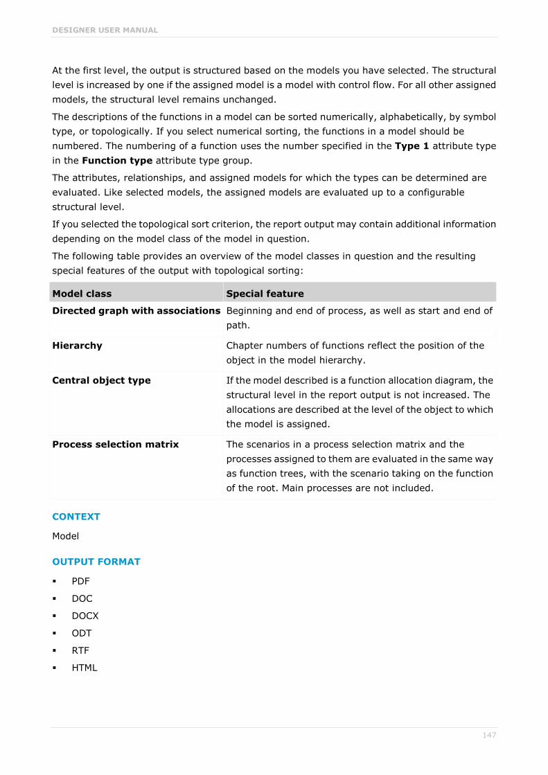
DESIGNER USER MANUAL
147
At the first level, the output is structured based on the models you have selected. The structural level is increased by one if the assigned model is a model with control flow. For all other assigned models, the structural level remains unchanged.
The descriptions of the functions in a model can be sorted numerically, alphabetically, by symbol type, or topologically. If you select numerical sorting, the functions in a model should be numbered. The numbering of a function uses the number specified in the Type 1 attribute type in the Function type attribute type group.
The attributes, relationships, and assigned models for which the types can be determined are evaluated. Like selected models, the assigned models are evaluated up to a configurable structural level.
If you selected the topological sort criterion, the report output may contain additional information depending on the model class of the model in question.
The following table provides an overview of the model classes in question and the resulting special features of the output with topological sorting:
Model class Special feature
Directed graph with associations Beginning and end of process, as well as start and end of path.
Hierarchy Chapter numbers of functions reflect the position of the object in the model hierarchy.
Central object type If the model described is a function allocation diagram, the structural level in the report output is not increased. The allocations are described at the level of the object to which the model is assigned.
Process selection matrix The scenarios in a process selection matrix and the processes assigned to them are evaluated in the same way as function trees, with the scenario taking on the function of the root. Main processes are not included.
CONTEXT
Model
OUTPUT FORMAT
DOC
DOCX
ODT
RTF
HTML
DESIGNER USER MANUAL
148
3.1.12.11.5 Output functions with connected objects
USE
Outputs the model attributes, the model graphic, and the functions including the objects connected to them for the selected process models.
Optionally, you can select the following connected objects:
Organizational elements
Executing organizational elements
Data elements (input/output data)
Supporting application systems
You can specify the evaluation direction between the functions and the connected objects. In addition, you can also evaluate assigned function allocation diagrams.
CONTEXT
Models of type:
EPC (event-driven process chain)
EPC (column display)
EPC (horizontal table display)
EPC (table display)
EPC (material flow)
EPC (row display)
Industrial process
Office process
PCD (process chain diagram)
PCD (material flow)
UML Activity diagram
VACD (value-added chain diagram)
OUTPUT FORMAT
RTF
HTML
TXT
DOC
XLS

DESIGNER USER MANUAL
149
3.1.12.11.6 Output model information
USE
Outputs information about the selected models, the objects contained in the model, and the relationships of the objects in the model. Apart from name and type, the groups, additional attributes, and model graphic can also be output.
For object relationships, you can also output the name and type of the target object.
CONTEXT
Models
OUTPUT FORMAT
RTF
HTML
TXT
DOC
XLS

DESIGNER USER MANUAL
150
3.1.12.11.7 Output model information considering various aspects
USE
Outputs model information including group structure as an Excel table.
A worksheet is created for each aspect. The worksheet lists all models in which the relevant aspect occurs.
The following aspects can be output:
Data
IT
Organizational elements
Targets/KPIs
Products/Services
Risks
Others
For each aspect, the related functions can be listed, as well. Individual or integrated evaluations can be carried out for function allocation diagrams (FAD). For integrated evaluations, the functions from the FAD are integrated in the model.
CONTEXT
Models and groups
OUTPUT FORMAT
XLS
XLSX

DESIGNER USER MANUAL
151
3.1.12.11.8 Output object information
USE
Outputs the relationships and target objects at definition level for the selected objects. Optionally, you can output the groups and the attributes for both the source and target objects.
The output is in table format.
CONTEXT
Object
OUTPUT FORMAT
RTF
HTML
DOC
XLS
DOCX
ODT
3.1.12.11.9 Process manual (example)
USE
This report script is a sample created in ARIS Architect in the design view. It shows how to create report scripts in ARIS Architect without having programming knowledge.
CONTEXT
Objects
OUTPUT FORMAT
DOC
DOCX
ODT
RTF
DESIGNER USER MANUAL
152
3.1.12.11.10 RA(S)CI - Output organizational participations in processes
USE
This report supplies information on which organizational elements participate in the activities (functions) of a process and in what manner. Organizational responsibilities and participations are output in a matrix.
The report returns plausible results if your processes and the organizational responsibilities for the individual activities conform with the modeling conventions required.
RA(S)CI stands for Responsible, Accountable, (Supportive), Consulted, Informed.
By default, this report does not return any Supportive information. To output this information, your script administrator must set the g_bRASCI variable to true.
The matrix shows which organizational unit participates in activities of a process and in what manner:
Responsible indicates who assumes execution responsibility. It shows who is responsible for performing an activity and who actually performs it, but also who assumes the disciplinary responsibility. Execution responsibility must be assigned to at least one role, although others (see Supportive) can be delegated to assist in the work required.
Accountable identifies the person ultimately answerable for the correct and thorough completion of a task. Thus, 'Accountable' may be the one in charge of managing the costs, i.e., the one who assumes project budget responsibility. The decides on and accepts connections are evaluated in order to mark this responsibility.
Supportive relates to the person supporting the person responsible (see 'Responsible') in performing the activity.
Consulted shows who has a consulting role. This organizational unit - typically a group of subject matter experts - is asked for advice prior to a final decision being made or a final action being taken.
Informed specifies who must be informed. It indicates who is kept up to date on the progress or completion of a task.
In the RACI matrix, RACI data is displayed under the following conditions:
The connections are used in the selected process model.
The connections are used in a function allocation diagram that is assigned to a function of the selected process model.

DESIGNER USER MANUAL
153
The result of the report is an Excel workbook containing several tables. Each process model included creates a table. The first table consists of a full list of the functions and organizational units of the process models included.
CONTEXT
Individual process
List of processes
Process hierarchy
OUTPUT FORMAT
XLS

DESIGNER USER MANUAL
154
3.1.12.12 What report output formats exist?
When you click the output button in the Reports bar, for example, Output PDF, the report is output in the selected format. You can change the output format by clicking the down arrow. The selection of output formats may be restricted based on the report. Possible output formats are:
DOC
DOCX
ODT
RTF
HTML
TXT
XLS
XLSX
XML
3.1.12.13 What is ARIS Aware (Dashboards)?
You can use the product ARIS Aware as visualizing component of ARIS Connect. Using ARIS Aware you combine information from many sources and visualize data as KPIs in charts on dashboards. ARIS Aware supports users in different departments across the enterprise with dashboards for evaluating a wide variety of data. It improves the transparency of the business and allows you to make the best decisions based on reliable data analytics. ARIS Aware is equipped with ready-to-go templates for common scenarios in the context of business process management, including Center of Excellence (CoE) (page 156), Business Usage Monitoring (page 176), Enterprise Architecture Management (page 180), Customer Experience Management (CXM) (page 166), Process Performance Management and Governance, Risk and Compliance Management. These templates can be extended and customized according to the individual needs of a company.

DESIGNER USER MANUAL
155
3.1.12.14 What are the ARIS Aware fields?
ARIS Aware can be divided into the fields Create dashboards and data feeds, store data, read data, configure dashboards, and show dashboards.
In the following the data collection via reports is described. Naturally, other kinds of data collection are possible, e. g., via data files that are manually uploaded to ARIS document storage (page 86).
CREATE DASHBOARDS AND DATA FEEDS
There, dashboards (page 129) and data feeds (page 131) are created and connected. Dashboards and data feeds are stored on the defined server.
STORE DATA
Database information to be compiled for dashboard display is gathered by different reports.
For some reports parameters can be specified. These parameterized reports are to be started frequently using report schedules. This keeps the dashboards up to date. The scheduled reports themselves trigger related reports. Each report collects specific pieces of information. The results are stored in ARIS document storage as XML report output files. These pieces of information are formed into dashboards. That is why dashboards correlate very closely to the set of executed reports.
READ DATA
If the data are requested to show dashboards, they are loaded from the ARIS document storage database and combined with extracted ARIS attributes of the XML files that are stored in the ARIS document storage database as well.
CONFIGURE DASHBOARDS
Dashboards can be configured for different items to be shown in different views in the portal and collaboration.
SHOW DASHBOARDS
Dashboards can be shown in different views in the portal and collaboration. You can use the supplied database United Motor Group to show various dashboards (page 132).
DESIGNER USER MANUAL
156
3.1.12.15 What is an alias of a URL?
An alias is always recommended to shorten the link used in dashboards and data feeds. You have to enter the path where the data are stored only, and not the complete URL.
This also enables the import of such data to a different server. In this case, you have to adapt the alias only .
3.1.12.16 What dashboards are available by default?
ARIS Aware offers many demo dashboards by default. Dashboards consist of charts that offer different visual analyses of the United Motor Group database content.
3.1.12.16.1 Based on Center of Excellence (CoE)
Here you can find information about Center of Excellence dashboards delivered by default. Consequently, the dashboards provide information about leadership and best practice for the focus area business concept via Business Process Modeling.
3.1.12.16.1.1 CoE - Aggregated Maturity Overview
The dashboard is shown on the Overview fact sheet of process models. It shows an aggregated view of all process models, considering the connect hierarchy as defined in the configuration, starting from the top level model, e.g., a Value-added chain diagram, down to the last level process model, e.g., level 4 EPC. The progress of the models in the hierarchy (subordinated models), is weighted by 70 % by default.
CHARTS
Aggregated maintaining progress
Shows the percentage of maintaining progress.
Data source Model/Database content
Calculation Calculates the aggregated percentage of the mandatory properties to be maintained, such as person responsible, validity date, etc.
Aggregated model count
Shows the count of involved process models.
Data source Model/Database content
Calculation Counts the processes modeled in the corresponding hierarchy level.
Aggregated release progress
Shows the percentage of processes that are not completed (not set), completed, and released.

DESIGNER USER MANUAL
157
Data source Model/Database content
Calculation Determines the percentage of processes that are not completed (not set), completed, and released.
EXAMPLE
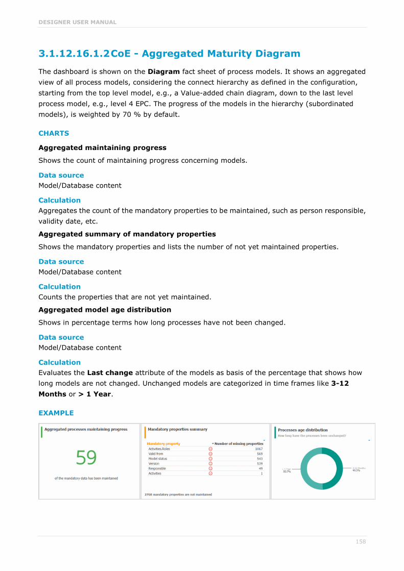
DESIGNER USER MANUAL
158
3.1.12.16.1.2 CoE - Aggregated Maturity Diagram
The dashboard is shown on the Diagram fact sheet of process models. It shows an aggregated view of all process models, considering the connect hierarchy as defined in the configuration, starting from the top level model, e.g., a Value-added chain diagram, down to the last level process model, e.g., level 4 EPC. The progress of the models in the hierarchy (subordinated models), is weighted by 70 % by default.
CHARTS
Aggregated maintaining progress
Shows the count of maintaining progress concerning models.
Data source Model/Database content
Calculation Aggregates the count of the mandatory properties to be maintained, such as person responsible, validity date, etc.
Aggregated summary of mandatory properties
Shows the mandatory properties and lists the number of not yet maintained properties.
Data source Model/Database content
Calculation Counts the properties that are not yet maintained.
Aggregated model age distribution
Shows in percentage terms how long processes have not been changed.
Data source Model/Database content
Calculation Evaluates the Last change attribute of the models as basis of the percentage that shows how long models are not changed. Unchanged models are categorized in time frames like 3-12 Months or > 1 Year.
EXAMPLE

DESIGNER USER MANUAL
159
3.1.12.16.1.3 CoE - Local Maturity # Dashboard
The dashboard is shown for selected process models and organizational charts.
CHARTS
Number of change requests for the model
Shows the number of change requests that has been submitted for the model by using the Submit change request mini workflow.
Data source Model/Database content
Calculation Counts and evaluates the number of submitted change requests.
Result of the semantic check
Shows the result of the Mandatory semantic check semantic check as symbol.
Data source Model/Database content
Calculation Accesses the result of the Mandatory semantic check semantic check.
Status of mandatory properties
Shows the maintained and total number of mandatory properties.
Data source Model/Database content
Calculation Evaluates how many mandatory properties are maintained compared to the total number of mandatory properties. The mandatory properties by default are Model status, Person responsible, Version, Validity, and Activities.
EXAMPLE

DESIGNER USER MANUAL
160
3.1.12.16.1.4 CoE - Global Maturity
The dashboard is shown for all process models and organizational charts within the database.
CHARTS
Validity date status
Shows, based on the property Validity, when the models will expire.
Data source Model/Database content
Calculation Evaluates the Validity attribute of all process models and organizational charts within the database.
Validity date overview
Lists the process models and organizational charts together with their Validity attributes in a table.
Data source Model/Database content
Calculation Evaluates the Validity attribute of all process models and organizational charts within the database.
Most shared processes
Shows the number of model sharing based on the Share model mini workflow.
Data source Model/Database content
Calculation Counts and evaluates the number of model sharings.
Owners with process responsibilities
Shows how often persons are assigned to process models as owner.
Data source Model/Database content
Calculation Evaluates the Person responsible attribute of all process models in the database.

DESIGNER USER MANUAL
161
EXAMPLE

DESIGNER USER MANUAL
162
3.1.12.16.1.5 CoE - Process Change Management
The dashboard shows governance information based on Process Governance.
CHARTS
Processes with change request
Shows the number of open change requests and the percentage of running and completed change requests that have been submitted for the models by using the Submit change request mini workflow.
Data source Model/Database content
Calculation Counts and evaluates the number of submitted change requests.
Number of overall change requests
Shows the total number of change requests that have been submitted for the models within three months by using the Submit change request mini workflow and how many of them are completed.
Data source Model/Database content
Calculation Counts and evaluates the number of submitted change requests.
Change requests over time
Shows the development of change requests within three months for the models based on the submission date of the change requests of the Submit change request mini workflow.
Data source Model/Database content
Calculation Evaluates the submission date of the change requests.
Processes with pending change requests
Shows seven models with the most open change requests.
Data source Model/Database content
Calculation Evaluates the state of the change requests.
Process owners with most change requests
Shows seven process owners with the most open change requests.
Data source Model/Database content
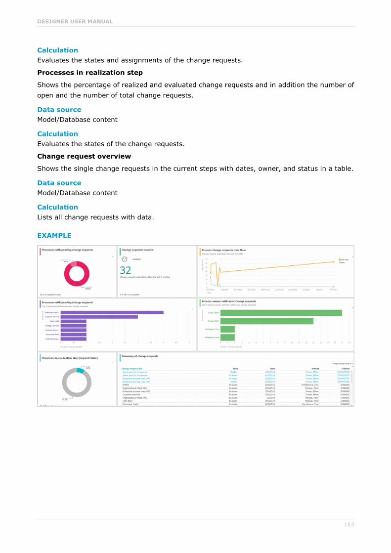
DESIGNER USER MANUAL
163
Calculation Evaluates the states and assignments of the change requests.
Processes in realization step
Shows the percentage of realized and evaluated change requests and in addition the number of open and the number of total change requests.
Data source Model/Database content
Calculation Evaluates the states of the change requests.
Change request overview
Shows the single change requests in the current steps with dates, owner, and status in a table.
Data source Model/Database content
Calculation Lists all change requests with data.
EXAMPLE

DESIGNER USER MANUAL
164
3.1.12.16.1.6 CoE - Human Task
The dashboard shows overall governance information about the human tasks submitted by Process Governance.
CHARTS
Number of all human tasks
Shows the number of all human tasks independent from the Process Governance process. The human tasks include, e. g., change requests, approvals, and custom Process Governance workflows. The Dashboard CoE - Human tasks can be filtered by using database and model context as well as by task information such as status and priority.
Data source Model/Database content
Calculation Counts all human tasks.
Human tasks over time
Shows when the most human tasks are submitted and assigned over time. The Dashboard CoE - Human tasks can be filtered by using database and model context as well as by task information such as status and priority.
Data source Model/Database content
Calculation Counts the number of human tasks that are daily submitted and assigned within a period selected.
Human tasks details
Lists the human tasks with details such as Priority, Creation date, Status, and Participant. The Dashboard CoE - Human tasks can be filtered by using database and model context as well as by task information such as status and priority.
Data source Model/Database content
Calculation Lists all human task including details in a table.
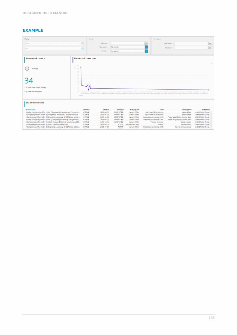
DESIGNER USER MANUAL
165
EXAMPLE
DESIGNER USER MANUAL
166
3.1.12.16.2 Based on Customer Experience (CXM)
Dashboards based content that is collected from Customer Experience (CXM) models.
3.1.12.16.2.1 Customer experience
Dashboard with an overall overview about the Customer experience and charts that show Customer experience from different angles.
CHARTS
Number of affected internal processes
Number of internal processes affected by customer touchpoints with bad experience.
Data source Report: CXM - Analyze customer experience
Report configurable No
Data collection Context: Customer journey landscape model type.
Collects all Customer journeys reachable from the current Customer journey landscape by following the Customer journey maps assigned. For each Customer journey map:
Checks for all Customer touchpoint if there is a connection to an internal process.
Counts all Customer touchpoints that have a connection to an internal process.
Checks for every Customer touchpoint if the Pain point attribute is specified.
Counts the Customer touchpoints with an activated Pain point attribute type (value true).
Checks for every Customer touchpoint if the Moment of truth attribute is specified.
Counts the Customer touchpoints with an activated Moment of truth attribute type (value true).
Checks for every Customer touchpoint if the Best practice attribute is specified.
Counts the Customer touchpoints with an activated Best practice attribute type (value true).
Data feed CXM - Analyze customer experience
Calculation Aggregated number of internal processes affected by customer touchpoints with bad experience.

DESIGNER USER MANUAL
167
Percentage of critical customer touchpoints
Overview of the percentage of critical customer touchpoints.
Data source Report: CXM - Analyze customer experience
Report configurable No
Data collection -.-
Data feed CXM - Analyze customer experience
Calculation Aggregated number of Customer touchpoints for which the Pain point attribute type is specified over the aggregated number of Customer touchpoints multiplied by 100.
Overall customer experience
Distribution of customer feelings over the whole customer journey landscape.
Data source Report: CXM - Analyze customer experience
Report configurable No
Data collection Context: Customer journey landscape model type.
Data are collected from all reachable Customer journeys via the current Customer journey landscape model type.
All contained Customer touchpoint occurrences of each Customer journey map are collected. The following data is count:
All customer touchpoints for which the Customer feeling attribute is specified as Positive.
All customer touchpoints for which the Customer feeling attribute is specified as Neutral.
All customer touchpoints for which the Customer feeling attribute is specified as Negative.
Data feed CXM - Overall customer experience
Calculation Aggregated number of Customer feeling values (positive, neutral, negative).

DESIGNER USER MANUAL
168
Customer journeys with good customer experience
Top seven customer journeys with good customer experience.
Data source Report: CXM - Analyze customer experience (TOP7)
Report configurable No
Data collection Context: Customer journey landscape model type.
Data are collected from all reachable Customer journeys via the current Customer journey landscape model type.
All contained Customer touchpoint occurrences of each Customer journey map are collected and all Customer touchpoints are count for which the Customer feeling attribute type is set to Positive.
Data feed CXM - Analyze customer journeys
Calculation Number of customer touchpoints for which the Customer feeling attribute type is specified with the value Positive over number of customer touchpoints per customer journey.
Customer journeys with bad customer experience
Top seven customer journeys with bad customer experience.
Data source Report: CXM - Analyze customer experience (TOP7)
Report configurable No
Data collection Context: Customer journey landscape model type.
Data are collected from all reachable Customer journeys via the current Customer journey landscape model type.
All contained Customer touchpoint occurrences of each Customer journey map are collected and all Customer touchpoints are count which have an activated Pain point attribute type (value true).
Data feed CXM - Analyze customer journeys
Calculation Number of Customer touchpoints for which the Pain point attribute type is activated over number of Customer touchpoints per Customer journey.

DESIGNER USER MANUAL
169
EXAMPLE

DESIGNER USER MANUAL
170
3.1.12.16.2.2 Responsibilities
Customer experience dashboard with business units and channel evaluations.
CHARTS
Business units with good experience
Top seven business units with good customer experience.
Data source Report: CXM - Responsibility (Ownership)
Report configurable No
Data collection Context: Customer journey landscape model type.
Starting from the current Customer journey landscape, all contained Ownership occurrences of the Ownership row and the associated Customer touchpoints of each Customer journey map are collected. Checks every Customer touchpoint and counts it, if the Customer feeling attribute is specified as Positive.
Data feed CXM - Responsible owner
Calculation Good experience ratio: Number of positive feelings divided by Number of customer touchpoints.
Business units with bad experience
Top seven business units with bad customer experience.
Data source Report: CXM - Responsibility (Ownership)
Report configurable No
Data collection Context: Customer journey landscape model type.
Starting from the current Customer journey landscape, all contained Ownership occurrences of the Ownership row and the associated Customer touchpoints of each Customer journey map are collected. Checks every Customer touchpoint and counts, if the Pain point attribute is activated (value true).
Data feed CXM - Responsible owner
Calculation Bad experience ratio: Number of pain points divided by Number of customer touchpoints.

DESIGNER USER MANUAL
171
Channels with good experience
Top seven channels with good customer experience.
Data source Report: CXM - Responsibility (Channel)
Report configurable No
Data collection Context: Customer journey landscape model type.
Starting from the current customer journey landscape, all contained occurrences of the Channel row and the associated touchpoints of each customer journey map are collected. Checks every Customer touchpoint and counts it, if the Customer feeling attribute is specified as Positive.
Data feed CXM - Responsible channel
Calculation Good experience ratio: Number of positive feelings divided by Number of customer touchpoints.
Channels with bad experience
Top seven channels with bad customer experience.
Data source Report: CXM - Responsibility (Channel)
Report configurable No
Data collection Context: Customer journey landscape model type.
Starting from the current customer journey landscape, all contained occurrences of the Channel row and the associated touchpoints of each customer journey map are collected. Checks every Customer touchpoint and counts, if the Pain point attribute is activated (value true).
Data feed CXM - Responsible channel
Calculation Bad experience ratio: Number of pain points divided by Number of customer touchpoints.

DESIGNER USER MANUAL
172
EXAMPLE

DESIGNER USER MANUAL
173
3.1.12.16.2.3 Customer journey map
Customer journey map dashboard with customer touchpoint evaluation and market potential.
CHARTS
Number of affected internal processes
Number of internal processes affected by customer touchpoints with bad experience.
Data source Report: CXM - Analyze customer experience
Report configurable No
Data collection Context: Customer journey landscape model type.
Collects all Customer journeys reachable from the current Customer journey landscape by following the Customer journey maps assigned. For each Customer journey map:
Checks for all Customer touchpoint if there is a connection to an internal process.
Counts all Customer touchpoints that have a connection to an internal process.
Checks for every Customer touchpoint if the Pain point attribute is specified.
Counts the Customer touchpoints with an activated Pain point attribute type (value true).
Checks for every Customer touchpoint if the Moment of truth attribute is specified.
Counts the Customer touchpoints with an activated Moment of truth attribute type (value true).
Checks for every Customer touchpoint if the Best practice attribute is specified.
Counts the Customer touchpoints with an activated Best practice attribute type (value true).
Data feed CXM - Analyze customer experience
Calculation Aggregated number of internal processes affected by customer touchpoints with bad experience.
Percentage of bad customer feelings
Overview of the percentage of negative customer touchpoints.
Data source Report: CXM - Analyze customer experience
Report configurable No
Data collection -.-

DESIGNER USER MANUAL
174
Data feed CXM - Analyze customer experience
Calculation Number of pain points divided by the number of customer touchpoints multiplied by 100.
Percentage of critical customer touchpoints
Overview of the percentage of critical customer touchpoints.
Data source Report: CXM - Analyze customer experience
Report configurable No
Data collection -.-
Data feed CXM - Analyze customer experience
Calculation Aggregated number of Customer touchpoints for which the Pain point attribute type is specified over the aggregated number of Customer touchpoints multiplied by 100.
Percentage of good customer feelings
Overview of the percentage of positive customer touchpoints.
Data source Report: CXM - Analyze customer experience
Report configurable No
Data collection -.-
Data feed CXM - Analyze customer experience
Calculation Number of customer touchpoints with value Positive for the Customer feeling attribute divided by the Number of customer touchpoints multiplied by 100.
Customer touchpoints with high market potential
Customer touchpoints with high market potential related to the transformation costs.
Data source Report: CXM - Analyze customer experience
Report configurable No
Data collection -.-

DESIGNER USER MANUAL
175
Data feed CXM - Analyze customer experience
Calculation Values from the Market potential attribute and Transformation costs attribute from customer touchpoints.
Importance and feelings of customer touchpoints
Importance and feelings that a customer associates with a customer touchpoint.
Data source Report: CXM - Analyze customer experience (TOP7)
Report configurable No
Data collection -.-
Data feed CXM - Importance vs. feelings
Calculation Values from the Customer feeling attribute and Importance to customer attribute from customer touchpoints.
EXAMPLE

DESIGNER USER MANUAL
176
3.1.12.16.3 Based on Piwik
Dashboards based on information that is collected by ARIS reports that access to Piwik data. Piwik is an open source analytics platform.
3.1.12.16.3.1 Piwik - Publications
Dashboard that includes an overall overview of the ARIS usage/consumption and six different charts for which you can select various evaluation periods such as last week, last month, and last year.
CHARTS
Number of visits over time
Top seven business units with good customer experience.
Data source Piwik - Global reports: VisitsSummary report
Data feed Piwik - Visit summary over time
Most viewed item types
Top seven item types most viewed over the selected time period, e.g. process.
Data source Piwik - Database-specific reports: CustomDimension report
Data feed Piwik - Most viewed item types
Most viewed items
Top seven items most viewed over the selected time period.
Data source Piwik - Database-specific reports: PageTitles report
Data feed Piwik - Most viewed item
Most searched keywords
Top seven searched keywords most viewed over the selected time period.
Data source Piwik - Database-specific reports: SiteSearchKeywords report
Data feed Piwik - Most searched keywords

DESIGNER USER MANUAL
177
Most viewed item types list
List of top fifty item types most viewed over the selected time period, e.g. process.
Data source Piwik - Database-specific reports: CustomDimension report
Data feed Piwik - Most viewed items types
Most viewed items list
List of top fifty items most viewed over the selected time period.
Data source Piwik - Database-specific reports: PageTitles report
Data feed Piwik - Most viewed items
Most searched keywords list
List of top fifty searched keywords most viewed over the selected time period.
Data source Piwik - Database-specific reports: SiteSearchKeywords report
Data feed Piwik - Most searched keywords
EXAMPLE
DESIGNER USER MANUAL
178
3.1.12.16.3.2 Piwik - Technical KPIs
Dashboard that shows technical KPIs regarding the ARIS usage/consumption in four charts for which you can select various evaluation periods such as last week, last month, and last year.
CHARTS
Browse engine distribution
Number of visits over the selected time period: visitors, unique visitors.
Data source Piwik - Global reports: BrowserEngines report
Data feed Piwik - Browser engines
Most used operation systems
Operation systems most used over the selected time period.
Data source Piwik - Global reports: OsVersions report
Data feed Piwik - Operating system version
Browser version summary
Browser versions most used over the selected time period.
Data source Piwik - Global reports: BrowserVersions report
Data feed Piwik - Browser version
Portal language summary
Portal language most used over the selected time period.
Data source Piwik - Global reports: Language report
Data feed Piwik - Portal language

DESIGNER USER MANUAL
179
EXAMPLE

DESIGNER USER MANUAL
180
3.1.12.16.4 Based on EA
Dashboards based on Enterprise Architecture (EA) information.
3.1.12.16.4.1 EA dashboard for organizational units
Shows a separate tab for organizational units, i. e. for object of type Organizational unit and Organizational unit type.
CHARTS
Systems having expired
Number of systems used by the selected organizational unit which are no longer standard.
Data source ARIS or ARIS and Alfabet:
Report: EA - Relations between organizational units and systems
Report: EA/Alfabet - Systems with lifecycle data
Data feed EA - Organizational unit - Systems expired
uses EA - Organizational unit (Systems with lifecycle data) as a sub-feed
EA - Organizational unit - Systems with lifecycle data
Calculation Checks via the End attribute if a system has expired
that supports an organizational unit via function or optionally via position or role or
that lies under the responsibility of an organizational role.
Systems phasing in
Number of systems used by the selected organizational unit which will become standard within the next twelve months.
Data source ARIS or ARIS and Alfabet:
Report: EA - Relations between organizational units and systems
Report: EA/Alfabet - Systems with lifecycle data
Data feed EA - Organizational unit (systems phasing in)
uses EA - Organizational unit (Systems with lifecycle data) as a sub-feed
EA - Organizational unit - Systems with lifecycle data
Calculation Checks via the Phase-in phase (start) attribute if a system is phasing in
that supports an organizational unit via function or optionally via position or role or
that lies under the responsibility of an organizational role.

DESIGNER USER MANUAL
181
Systems phasing out
Number of systems used by the selected organizational unit which will be retired within the next twelve months.
Data source ARIS or ARIS and Alfabet:
Report: EA - Relations between organizational units and systems
Report: EA/Alfabet - Systems with lifecycle data
Data feed EA - Organizational unit (systems phasing out)
uses EA - Organizational unit (Systems with lifecycle data) as a sub-feed
EA - Organizational unit - Systems with lifecycle data
Calculation Checks via the Phase-out phase (start) attribute if a system is phasing out
that supports an organizational unit via function or optionally via position or role or
that lies under the responsibility of an organizational role.
Systems expiring
Number of systems used by the selected organizational unit which will become non-standard within the next twelve months.
Data source ARIS or ARIS and Alfabet:
Report: EA - Relations between organizational units and systems
Report: EA/Alfabet - Systems with lifecycle data
Data feed EA - Organizational unit (standard systems expiring)
uses EA - Organizational unit (Systems with lifecycle data) as a sub-feed
EA - Organizational unit - Systems with lifecycle data
Calculation Checks via the Start attribute if a system is expiring
that supports an organizational unit via function or optionally via position or role or
that lies under the responsibility of an organizational role.

DESIGNER USER MANUAL
182
Usage of non-standard systems
Distribution of standard and non-standard systems used by the selected organizational unit.
Data source ARIS or ARIS and Alfabet:
Report: EA - Relations between organizational units and systems
Report: EA/Alfabet - Systems with lifecycle data
Data feed EA - Organizational unit (standard versus non-standard systems) uses EA - Organizational unit (Systems with lifecycle data) as a sub-feed
Calculation Checks via the Standardization status attribute if a system used is non-standard
that supports an organizational unit via function or optionally via position or role or
that lies under the responsibility of an organizational role.
Systems compared by cost and criticality
Portfolio of systems used by the selected organizational unit categorized by cost, criticality, and interface count.
Data source ARIS Architect:
Report: EA - Relations between organizational units and systems
Report: EA - Systems with data
Data feed EA - Organizational unit - Systems with data
Calculation Compares systems via the Costs per unit and Critically attributes
that supports an organizational unit via function or optionally via position or role or
that lies under the responsibility of an organizational role.
System replacement candidates by capability redundancy
Seven pairs of systems used by the selected organizational unit with the greatest overlap of capabilities.
Data source ARIS:
Report: EA - Relations between organizational units and systems
Report: EA - Systems redundancies
Data feed EA - System - System redundancies
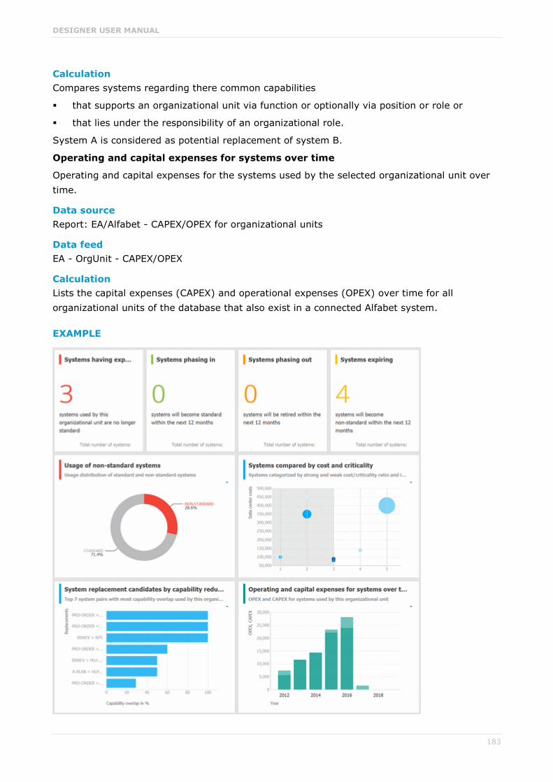
DESIGNER USER MANUAL
183
Calculation Compares systems regarding there common capabilities
that supports an organizational unit via function or optionally via position or role or
that lies under the responsibility of an organizational role.
System A is considered as potential replacement of system B.
Operating and capital expenses for systems over time
Operating and capital expenses for the systems used by the selected organizational unit over time.
Data source Report: EA/Alfabet - CAPEX/OPEX for organizational units
Data feed EA - OrgUnit - CAPEX/OPEX
Calculation Lists the capital expenses (CAPEX) and operational expenses (OPEX) over time for all organizational units of the database that also exist in a connected Alfabet system.
EXAMPLE

DESIGNER USER MANUAL
184
3.1.12.16.4.2 EA dashboard for IT systems
Shows a separate tab for IT systems, i. e. for object of type Application system type.
CHARTS
Organizational units with most system supports
Based on process support maps, seven organizational units with most processes actively supported by the selected system.
Data source ARIS Architect:
Report: EA - System support
Data feed EA - System - Supported organizational units
Calculation Lists all supported objects, that are Application system type object types. These objects are identified via the Process support unit, the Organizational unit, and Function objects connected to the IT system.
Support distribution by organizational units
Based on process support maps, all organizational units supported by the selected system and their distribution.
Data source ARIS Architect:
Report: EA - System support
Data feed EA - System - Supported organizational units
Calculation Shows the distribution of supported objects, that are Application system type object types. These objects are identified via the Process support unit, the Organizational unit, and Function objects connected to the IT system.
Processes with most system supports
Seven processes with most functions actively supported by the selected system - not based on process support maps.
Data source ARIS Architect:
Report: EA - System support for VACDs
Data feed EA - System Supported processes

DESIGNER USER MANUAL
185
Calculation Counts and ranks the systems supported per processes.
Traversing the hierarchy of value-added chain diagrams (VACDs), searches for all functions supporting IT systems. Functions support IT systems if they are connected via the connection type supports in event process chain diagrams (EPCs) that are assigned to VACDs.
Support distribution by processes
All processes supported by the selected system and their distribution - not based on process support maps.
Data source ARIS Architect:
Report: EA - System support for VACDs
Data feed EA - System Supported processes
Calculation Lists the systems supported per processes together with the percentage distribution, based on the rank.
Traversing the hierarchy of value-added chain diagrams (VACDs), searches for all functions supporting IT systems. Functions support IT systems if they are connected via the connection type supports in event process chain diagrams (EPCs) that are assigned to VACDs.
System replacement candidates by capability overlap
Seven replacement possibilities involving the selected system as source or target with the most capability overlap.
Data source ARIS Architect:
Report: EA - System redundancies
Data feed EA - System - System redundancies
Calculation Compares systems regarding there common capabilities.
Operating costs by cost type
Operating costs for the selected IT system by different cost types over time.
Data source ARIS Architect:
EA/Alfabet - System costs
Data feed EA - System (costs over time)
Calculation Lists all IT systems of the database that also exist in Alfabet. Per system and year all cost values for the various cost types specified are listed.

DESIGNER USER MANUAL
186
EXAMPLE
DESIGNER USER MANUAL
187
3.1.12.16.4.3 EA dashboard for objectives
Shown as side bar for the diagram view of the model types Strategy diagram and Objective diagram.
CHARTS
Objectives
Shows all objectives in the model and their goal accomplishments over all KPIs.
Data source ARIS Architect:
Report: EA - Models and objectives
Report: EA - Objectives with data
Data feed EA - Goal accomplishment (objectives)
Calculation Lists all Strategy diagram and Objective diagram model types and the objectives contained with their goal accomplishments.
KPIs of the objective
Shows the KPIs of the objective selected in the diagram and their respective values.
Data source ARIS Architect:
Report: EA - Objectives and KPIs
Report: EA - KPIs with data
Data feed EA - Goal accomplishment (KPIs per objective)
Calculation Lists all all objectives and their KPIs whose accomplishments are calculated according to the Balanced Scorecard methodology.

DESIGNER USER MANUAL
188
EXAMPLE
DESIGNER USER MANUAL
189
3.2 Collaborate with users
Collaboration is the platform for cooperation across teams. With Collaboration, information can be exchanged faster, knowledge can be shared, and cooperation across borders is improved.
3.2.1 Getting started
These five steps are an optimal start to Collaboration:
1. Create (page 189) a user profile.
2. Search (page 190) for groups and people who provide interesting content.
3. Create filters and check (page 195) for new information.
4. Comment on (page 193), share, flag posts, etc.
5. Invite (page 198) others to Collaboration.
You started using Collaboration to exchange information, share knowledge, etc.
3.2.2 Open Collaboration
Open Collaboration to exchange information, share knowledge, etc.
Prerequisites Collaboration is activated in ARIS Administration configuration.
You have at least the ARIS Connect Viewer license privilege.
You have the required access privilege (page 202) in ARIS Architect.
Procedure
1. Open ARIS Connect and log in with your user name and password.
2. Click Collaboration.
Collaboration opens.
3.2.3 Create or edit a user profile
Specify your user profile to provide other users with information about your areas of activity and your interests.
Procedure
1. Click your user name on the left, then click Edit profile on the right. Your profile page for Collaboration is displayed.
2. Upload a picture in JPG, PNG, or GIF format, with the specified maximum size.
If your user profile in ARIS Administration already includes a picture, it is also displayed in Collaboration. If a different picture is uploaded in ARIS Connect or in Collaboration, it is automatically transferred to the other application.
3. Click Edit to specify the trimming and size of the picture for Collaboration.
4. Select the preferred picture trimming by dragging the picture with the mouse.

DESIGNER USER MANUAL
190
5. Enlarge ( ) or reduce ( ) the picture.
6. Click OK.
7. Enter the title of your position in the company.
8. Describe your activities.
9. Specify keywords that will enable colleagues looking for particular information or expertise to find you. Use a comma as the separator.
10. Enter your telephone number.
11. Specify whether colleagues should be able to post information (Allow others to post to my feed) and submit comments (Allow others to comment on activities in my feed) in your feeds. To do this, enable the check box for the relevant option.
12. Click OK.
Your profile is changed. The information is now available to other users.
3.2.4 Find users and groups and follow their feeds
Look for colleagues or groups to find interesting contacts and information.
Procedure
1. Enter the name of the user or group in the global Find box at the top right ( ). The search results are displayed during input.
2. Continue entering characters until the relevant user or group is displayed.
3. Click the name you are looking for. The profile of the user or the group is displayed with all posts.
4. For users and public groups, click Follow. For private groups, click Send request. (Private
groups are identified as follows: .)
When you follow users, you have access to the posts that they publish in their feeds. In private groups, a coordinator needs to confirm your request before you are allowed access to this group's posts, comments, etc. In public groups you have immediate access to the group. The feeds you follow are displayed under My feed and the groups you follow under Groups. To stop following a user or group, click Unfollow in the user or group profile. Users who are following your feeds are displayed under Followers in your profile. Users and groups you are following are displayed under Following in your profile.
Tip
To find groups, you can also use the group search function (Groups > Find groups > All groups).
Alternatively, you can find out which groups and feeds another user follows from the user's profile (Global Search > User XY > Following).
You can also use the global search to search for keywords, in order to find interesting feeds, users, and groups.

DESIGNER USER MANUAL
191
3.2.5 Follow and comment on content in the portal as a user
Follow interesting content in the portal to be informed about updates, etc., in Collaboration.
Prerequisite
You have the required access privilege (page 202) in ARIS Architect.
Procedure
1. Open the process you want to follow.
2. Click Comment in the bar panel if the bar is not activated yet.
3. Click Follow.
4. To comment, write or copy your text into the input box. Up to 2000 characters are available.
5. Click Tag.
6. Enter the words to be used as keywords (page 201) in the tag input box, e.g., BPM. Alternatively, select an existing tag from the list of tags. It is displayed as soon as you enter a letter that is part of an existing tag. Press the Enter key after each keyword.
7. Click Link.
8. Insert a link to a Web site that contains more detailed information.
9. Click Add link. The link is checked and added.
10. Click File. The Select document dialog is displayed.
11. Click Upload new document to upload one of your own documents. The dialog opens.
12. Select the file you want to upload and enter the relevant additional information.
13. Click Upload.
14. Enable the check box of the document you want to add to your post.
15. Click OK.
16. Click Post.
Your comment is posted, and the processes you follow are displayed under My portal feeds in Collaboration. To stop following content, click Unfollow in the row of the relevant content.

DESIGNER USER MANUAL
192
3.2.6 Publish posts
Post information that could be of interest to your colleagues, or start a discussion on a particular topic.
Prerequisite
You have the required access privilege (page 202) in ARIS Architect.
Procedure
1. Click My feed, the profile of the relevant user, the relevant group, or All company feed, depending on whether the information is to be displayed only to those users who follow your feeds, only to the members of a certain group, or to all users. If you post information to All company feed, it is possible that your information will not be seen by the relevant users, as some users do not use All company feed due to the large number of posts and the associated complexity.
2. Enter or copy your text into the input field. Up to 2000 characters are available.
3. To create a link to another user in the text, enter an '@' at the relevant point in the text, immediately followed by the name of the user. The search results are displayed during input.
4. Continue entering characters until the relevant user or group is displayed.
5. Click the name you are looking for.
6. Click Tag.
7. Enter the words to be used as keywords (page 201) in the tag input box, e.g., BPM. Alternatively, select an existing tag from the list of tags. It is displayed as soon as you enter a letter that is part of an existing tag. Press the Enter key after each keyword.
8. Click Link.
9. Insert a link to a Web site that contains more detailed information.
10. Click Add link. The link is checked and added.
11. Click File. The Select document dialog is displayed.
12. Click Upload new document to upload one of your own documents. The dialog opens.
13. Select the file you want to upload and enter the relevant additional information.
14. Click Upload.
15. Enable the check box of the document you want to add to your post.
16. Click OK.
17. Select the target group (page 200) by entering the first letters of the relevant group, then select one of the options displayed. By default, a new post is public.
18. Click Post.
Your post is published. If you have published something in your feed, the text is also displayed in the company feeds. If you have posted something to another user's feed, this post is also displayed in the company feed and if you are following the other user's feed, this post is displayed

DESIGNER USER MANUAL
193
in your feed as well. If you published a post in a private group you are a member of, the post is shown only to group members.
To remove the post from your feeds, click Delete. Administrators can delete posts made by all users.
3.2.7 Comment on, share, flag posts, etc.
Depending on whether a post is your own or from another user, you can perform different actions.
Prerequisites The Like button, commenting on and sharing content, creating bookmarks, and flagging
posts are activated in ARIS Administration configuration.
You have the required access privilege (page 202) in ARIS Architect.
Procedure
1. Open the page containing the relevant post.
2. Click Like to show other users what interests you. The user who wrote the post receives a notification, if they have the relevant notification setting. The post is also flagged
accordingly and added to your filter. To cancel your Like, click Unlike.
3. Click Comment to enter a comment or further information for a post. You can also add a link to a Web site.
4. Click Share to comment on a post by another user and publish it in your own feeds. To remove the post from your feeds, click Delete. Administrators can delete posts made by all users.
5. Click More > Bookmark to add a post to your filters, so that you can easily find it again
(Filters > My bookmarks).
6. Click Edit or More > Edit to change or correct a post or comment you already published. Editing is possible as long as no other user has liked or commented on your post or comment yet.
7. Click More > Flag if you want the Collaboration administrator to review a post you think is inappropriate.
Depending on the selected action, the affected users receive a message by e-mail.

DESIGNER USER MANUAL
194
3.2.8 Add documents to posts
You can use documents from ARIS document storage in your posts. Use documents that have already been uploaded to ARIS document storage or upload new documents yourself.
Prerequisite
Using documents from ARIS document storage is activated in the ARIS Administration configuration.
Procedure
1. Add your post (page 192) or comment to the relevant feed ( My feed, All company feed, or your group feeds).
2. Click File. The Select document dialog is displayed.
3. Click Upload new document to upload one of your own documents. The dialog opens.
4. Select the file you want to upload and enter the relevant additional information.
5. Click Upload.
6. Enable the check box of the document you want to add to your post.
You have added a document to your post.
3.2.9 View notifications and specify settings
Read your internal notifications and specify the situations in which you want to receive a notification about activities in Collaboration as well as the notification frequency.
Procedure
1. Click View notifications. Your notifications are displayed. Various filters provide you with a better overview, e.g., All, Unread, Read.
2. Click Change your notification settings. Your notification settings are displayed.
3. Specify the situations in which you want to be informed about activities by other users, groups, or portal feeds. In each case, decide whether you want to receive the notification as an internal notification in Collaboration (In-app), or as an E-mail.
4. Specify the notification frequency, e. g., Daily digest. If you do not want to receive e-mail notifications, select Never for the relevant situation.
5. Click OK.
Your settings are saved. From now on, you will be notified according to your specifications. The time for daily digest e-mail and the day for weekly digest e-mail are defined by the Collaboration administrator.

DESIGNER USER MANUAL
195
3.2.10 Define filters
Define custom filters to find interesting posts quickly and easily using keywords or to gain a better overview.
Prerequisite
Creating filters is activated in ARIS Administration configuration.
Procedure
1. Click Create filter. The form for creating a filter opens.
2. Select the relevant filter criteria, e.g., whether you want all feeds or only feeds you follow to be included in the filter.
3. Enter a name for the filter.
4. Specify the keywords that can be used to find relevant posts. Use a space to separate the keywords.
5. Click OK.
The filter is saved and is displayed under Filters. Click the filter name to display the posts that contain the specified keywords.
To change a saved filter, click Filter XY > Edit filter. To delete filters that you no longer
require, click Delete filter.
3.2.11 Use tags
Use tags to categorize posts using keywords. This enables other users to find posts on interesting topics more easily.
Prerequisite
Creating tags and filtering using tags are activated in the ARIS Administration configuration.
Procedure
1. Add your post (page 192) to the relevant feed ( My feed, All company feed, or a group feed).
2. Click Tag.
3. Enter the words to be used as keywords (page 201) in the tag input box, e.g., BPM. Alternatively, select an existing tag from the list of tags. It is displayed as soon as you enter a letter that is part of an existing tag. Press the Enter key after each keyword.
4. Click Post.
Your post is published. The keywords entered as tags are shown below the post. You can add or delete tags at any time.

DESIGNER USER MANUAL
196
3.2.12 Filter feeds by means of tags
Use tags (page 201) to filter feeds using keywords.
Prerequisite Creating tags and filtering using tags are activated in the ARIS Administration configuration.
There are tags for the feed.
Procedure
1. Open the relevant feed overview ( My feed, All company feed). The tags are displayed above the feeds.
2. Click the tags for which you want to see posts. You can combine multiple tags. Activated tags are indicated in color.
You are shown the posts containing the tags selected.
To cancel the filter, click the selected keywords again.
3.2.13 Use hashtags
Use hashtags (page 201) to categorize posts using keywords or topics. This enables other users to find posts on interesting topics more easily.
Procedure
1. Add your post (page 192) or comment to the relevant feed ( My feed, All company feed, or your group feeds).
2. Enter the word to be used as a keyword, preceded by a # symbol, e.g., #BPM, or enter a sentence. Alternatively, select an existing hashtag from the list.
3. Publish (page 192) the post.
Your post is published and the keyword entered as a hashtag is highlighted in color as a link. Tags are automatically created for hashtags so that they can be used to filter feeds.
If a user clicks the hashtag, all post and comments subsequently entered are displayed on a separate page. A hashtag can be saved as a filter (page 195). You can then use the same hashtag in the filter definition, e.g., #BPM.
3.2.14 Find help
In addition to this online help, there are various ways you can find support in Collaboration.
Procedure
Publish a post containing your question and use the hashtag (page 201) #Help.
This keyword enables other users to find and reply to your question. Alternatively, contact your system administrator.

DESIGNER USER MANUAL
197
3.2.15 Work with groups
3.2.15.1 Create, edit or delete a group
Create your own group if you cannot find any interesting groups or you need a group for your team. Groups enable users to collaborate in a team and to participate in a special interest group or a particular topic.
Prerequisite
Creating groups is activated in ARIS Administration configuration.
Procedure
1. Click Create group.
2. Enter the name of the group and the short name.
3. Describe the group's interests, so that your group can be found by other users. The best way to do this is to use keywords.
4. If necessary, specify an additional coordinator who will manage the group profile and
privileges ( Add coordinator). As the creator of the group, you are automatically the coordinator.
5. Enable the relevant privacy option (Public/Private).
6. For private groups, you can follow portal feeds (page 198).
7. Click OK.
Your group is created. It is displayed under Groups. Using tags, other users can find the group and follow its posts. In private groups, only members are able to read the posts. The group's name and description will, however, be visible in search results for non-members, as well.
To edit or delete a group, click the relevant group name under Groups. Then click Edit group on the right. The group's profile page is displayed. Make the required changes or click Delete group.

DESIGNER USER MANUAL
198
3.2.15.2 Invite other users to join a group
Invite other users to become a member in a specific group.
Procedure
1. Activate the group you want to issue an invitation for.
2. In the Add colleagues box, enter the name of the person you want to invite.
3. Click Add.
The user receives a notification that they have been invited to join a private group. This user can
then request membership of the group ( Find groups > Send request). If the group coordinator approves (page 199) the request, the user can read the posts, comments, etc., by this group, and can himself post content in the group.
Group coordinators can add more users to a group directly (Add colleagues). That user immediately becomes a member of the group and receives the posts, comments, etc., by the group ( My feed).
3.2.15.3 Follow portal contents as a group
Follow interesting content for private groups in ARIS Connect to be informed about updates, etc., in Collaboration. This enables a private group, e.g., a project team, to jointly discuss and edit relevant processes.
Prerequisites The group is a private group.
You are the coordinator of the group.
The item from ARIS Connect must be followed as a portal feed in Collaboration.
You have the required access privilege (page 202) in ARIS Architect.
Procedure
1. Activate the group that is to follow portal feeds.
2. Click Edit group.
3. Click Follow portal feeds. The Find portal feed dialog opens.
4. Enter a search term for finding the portal feed. Please ensure that the spelling is correct.
5. Click Find or press the Enter key.
6. Click the required portal feed in the search result.
7. Click OK in both the dialog and the group.
Using the Following button, the group can view the portal feed. Comments, etc., are shown directly in the group. To unsubscribe a group from a portal feed, the group coordinator removes the portal feed from the list of feeds followed by the group (Group XY > Edit group > Followed portal feeds > Delete).
Users of the group are notified when the portal feed has changed or comments have been added to it.

DESIGNER USER MANUAL
199
3.2.16 Edit requests to join private groups as a coordinator
Edit requests for group memberships.
Prerequisite
The group is a private group you are the coordinator of.
Procedure
1. Open the group.
2. Click Requests. The user requests are displayed.
3. For each request, click Approve or Deny.
If the user was accepted as a group member, the user will be notified accordingly and displayed in the list of followers. If the user was denied membership the user and all other group coordinators receive a corresponding notification.
3.2.17 Grant/revoke group users coordinator privileges
Grant additional group members coordinator privileges or revoke them from them.
Procedure
1. Open the private group.
2. Click Followers. The members of this group are displayed.
3. In the row for the group member you want to grant/revoke coordinator privileges to/from, click Grant or Revoke. The button always shows the command that can be executed next, i.e., Revoke if the user has administrator privileges, and vice versa.
The user is granted coordinator privileges (page 202) or they are withdrawn. The user receives a notification. If a user is granted coordinator privileges all other coordinators of the group receive a notification, as well.
A coordinator can cancel group membership only if another coordinator withdraws the coordinator privileges from the user first.
Tip
The Remove button removes the user from the group. The Revoke button revokes the user's coordinator privileges.

DESIGNER USER MANUAL
200
3.2.18 Valuable information
This section provides background information to assist you in carrying out the relevant procedures.
3.2.18.1 What is a feed?
Feeds contain the posts (page 192) in Collaboration, which for example, can be commented (page 193) on. The posts are categorized as follows:
My feed
Shows the posts and comments by the users from Collaboration whose feeds you follow.
All company feed
Shows all posts and comments by users and public groups from Collaboration.
My portal feeds
Displays a linked list of the portal feeds you follow. Portal feeds are only available if Collaboration is used within ARIS Connect.
3.2.18.2 Which target groups can be assigned to posts?
The following target groups can be selected for posts (page 192):
Private
Only the creator can see this group. You can use it to keep your own notes.
Public
All users can see this group.
Public Collaboration group
Only members of the selected public group(s) can see this group. Multiple selection is possible.
Private Collaboration group
Only members of the selected public group(s) can see this group. Multiple selection is possible, but you can assign only groups you are a member of.
ARIS user group (ARIS Administration)
Only members of the selected ARIS user group(s) can see this group. Multiple selection is possible, but you can assign only groups you are a member of.
By default, a new post is public. Any combination of ARIS user groups, public Collaboration groups, and private Collaboration groups is possible. It is not possible to assign users.
In a post, you can move the mouse pointer over the group symbol ( ) to view the names of assigned groups.
The Collaboration administrator can view all posts, even the private ones.

DESIGNER USER MANUAL
201
3.2.18.3 What does following posts mean?
When you follow users, you have access to the posts that they publish in their feeds. In private groups, a coordinator needs to confirm your request before you are allowed access to this group's posts, comments, etc. In public groups you have immediate access to the group.
The feeds you follow are displayed under My feed and the groups you follow under Groups. To stop following a user or group, click Unfollow in the user or group profile. Users who are following your feeds are displayed under Followers in your profile. Users and groups you are following are displayed under Following in your profile.
3.2.18.4 What does Like mean?
By clicking on Like under a post, you are telling other people that you are giving this post a positive rating, but without leaving a comment. Just like a comment, this is shown along with your
user name below the post. To cancel your Like, click Unlike.
3.2.18.5 What is a timestamp?
A timestamp (page 193) indicates when a post was last updated in Collaboration. Example: Last update was 2 hours ago. Timestamp = 2 h.
3.2.18.6 What is a tag?
Tags are used to categorize posts using keywords, making them easier to find (page 196). The keywords entered as tags are shown below the post. Tags are automatically created for hashtags so that they can be used to filter feeds.
3.2.18.7 What is a hashtag?
Hashtags are used to categorize posts and comments using keywords or topics, making them easier to find. The keyword entered as a hashtag is displayed as a link, highlighted in color. If a user clicks the hashtag, all post and comments subsequently entered are displayed on a separate page. A hashtag can be saved as a filter (page 195). You can then use the same hashtag in the filter definition, e.g., #BPM.
A hashtag consists of the # character followed by a keyword or phrase. There is no space after the # and the phrase does not contain any punctuation marks.
Examples
#BPM
#Optimize your processes using social collaboration

DESIGNER USER MANUAL
202
3.2.18.8 What does flagging a post mean?
You can send (page 193) posts you deem inappropriate to the Collaboration administrator for review. The administrator decides whether the post will be deleted or not.
3.2.18.9 Which group types exist?
Groups can be created (page 197) for teams, departments, interest groups, topics, projects, etc. There are public and private groups. Public groups are open to all users. For private groups, a coordinator decides who is to be granted access (page 199) to the group.
3.2.18.10 Which access rights of ARIS Architect are relevant to Collaboration?
For some interactions in Collaboration, users need special access privileges, for example, to post on portal feeds. These access privileges are assigned in <aba>. You can synchronize the privileges in Collaboration manually, after you edited them in ARIS Architect. The following database access rights are relevant to Collaboration:
No access (----)
No portal content is displayed.
Read (r---)
Portal content is displayed. Users can read posts added to models, and they can like, share, bookmark, tag, and flag them. However, they cannot comment on models.
Read + Comment (rc--), Read + Write (rw--) (and all other types of rw access)
Portal content is displayed. Users can use all functions of Collaboration.
For detailed information about access rights, refer to the help in ARIS Architect (ARIS Configuration and Administration).

DESIGNER USER MANUAL
203
3.3 Use the repository
The repository contains, e.g., databases and documents of the selected server. In the database, you can navigate to a database group and edit its content, e.g., rename models and objects.
3.3.1 Create and edit models
The Model Editor allows you to edit existing and new models (page 203) in ARIS Connect. Using the ARIS Connect Designer license privilege you can create new models (page 203) directly in the portal, as well as edit (page 212) or create models (page 203) in the repository.
You can access the entire modeling functionality of Model Editor via buttons and bars (page 264) that you can use to efficiently edit your models.
If you have created or opened a model, you can set up the perspective (page 206) and adjust it to your own needs. Modeling (page 212) your organization, processes, data, etc., is just as simple as extended model editing (page 244). In addition to the graphic information, you can add further information to your models using attributes (page 221) that can be placed in the model as a symbol (page 259) or a text (page 255), if necessary.
Of course, you can also add comments to models and discuss models with other users.
To use Model Editor, you need to have the ARIS Connect Designer license.
3.3.1.1 Create/Import a model
Model Editor allows you to create new models or use models imported from ARIS Express (http://www.ariscommunity.com/aris-express).
3.3.1.1.1 Create new model
You can create new models in order to for example, model procedures as a control flow or model the data generation and usage.
Prerequisite
You have the ARIS Connect Designer license privilege.
Procedure
In the portal
1. Open ARIS Connect and log in with your user name and password.
2. Click Portal if it is not activated yet.
3. Click Create model on the Home tab. The dialog opens.
4. Enter a name for the new model in the Model name box.

DESIGNER USER MANUAL
204
5. Click the Model type box and enter part of the model type name. All model types (page 269) are displayed whose names contain the term you entered.
6. Select the required model type. The Target area displays the database and group names. This is where the new model will be stored.
7. Click Change if you want to store the model in a different database and/or group. The Select target group dialog opens.
8. Select the required database in the Database box.
9. Select the required group.
10. Click OK. The Select target group dialog closes.
11. Check your input.
12. Click OK. The Create model dialog closes.
In the repository
1. Click Repository if it is not activated yet.
2. Select the database group in which you want to create a new model. When you select the group, its content is displayed.
3. In the upper right, click Create model. The dialog opens.
4. In the Model name box specify the name that the new model is to be created with in the selected group.
5. Click the Model type box and enter part of the model type name. All model types (page 269) are displayed whose names contain the term you entered.
6. Select the required model type.
7. Click OK.
The new model is created and opened in a new tab. You can set up Model Editor (page 206) and model the model.
3.3.1.1.2 Create a new model using an assignment
You can assign models to objects. The assignment enables you to describe objects in independent models in more detail, for example. Assigned models are displayed by way of an assignment icon at the object and can be opened by double-clicking the assignment icon.
Procedure
1. In the open model, click the object to which you want to assign a new model.
2. Activate the Start (page 275) tab bar.
3. Click Assignment > Create assignment. The dialog opens.
4. Select the required model type. The model types that are allowed for the selected object by the method and by the method filter in use are available for selection.
5. Enter the relevant model name. The name of the selected object is suggested as a model name.
DESIGNER USER MANUAL
205
6. Click OK.
The new model is assigned to the selected object and opens on a separate tab. You can model the required content.
3.3.1.1.3 Create group
You can create a new group in which you can store models and objects.
Procedure
1. Click Repository if it is not activated yet.
2. Select the database group in which you want to create a new group. When you select the group, its content is displayed.
3. In the upper right, click Create group. The dialog opens.
4. Enter the required name in the Name box.
5. Click OK.
The new group is created as a subgroup of the selected one and you can store models and objects in it.
3.3.1.1.4 Import ARIS Express model
You can import a model from ARIS Express and use it in ARIS Connect. ARIS Express saves models in files of the ARIS Document Format format (adf).
Prerequisite The model is of a model type allowed by ARIS Connect and by the method filter you are using.
You have a Designer license.
Procedure
1. Click Repository if it is not activated yet.
2. Select the database group into which you want to import the ARIS Express model. When you select the group its content is displayed and a down arrow is shown next to the name.
3. Click the down arrow and select Import ARIS Express model. The dialog opens.
4. Click Select file and use the File Upload dialog to navigate to the group in which the model is stored in ADF format.
5. Select the relevant ADF file and click Open.
a. The selected model is imported if an ARIS Express filter or an ARIS Express template is available.
b. If no ARIS Express filter or ARIS Express template is available, you are asked whether you still want to import the model. If you do import the model, it will not look the same as in ARIS Express. Click OK.
6. Then import the ARIS Express filter and/or the ARIS Express template if you want the imported model to appear exactly as it does in ARIS Express.
The imported model is stored in the selected group and you can open it for editing.

DESIGNER USER MANUAL
206
3.3.1.1.5 Import BPMN file
You can import (page 286) data from a BPMN file and use the BPMN diagram that was generated by the import in ARIS Connect.
Prerequisites The method filter you are using allows BPMN diagrams.
You have a Designer license.
Procedure
1. Click Repository if it is not activated yet.
2. Select the database group into which you want to import the BPMN diagram. When you select the group its content is displayed and a down arrow is shown next to the name.
3. Click the down arrow and select Import BPMN diagram. The dialog opens.
4. Click Select file and navigate to the relevant BPMN file.
5. Select the BPMN file and click Open.
The BPMN diagram is stored in the selected group, and you can open it for editing on a tab.
3.3.1.2 Customize Model Editor
If you create a new model in ARIS Connect or open an existing model for editing, the model is displayed on a separate tab and the Model Editor is activated. You can set up the Model Editor user interface according to your requirements. In addition, you can apply templates to specify the appearance of model items. The Model Editor provides you with the functionality to
edit models.
create new models.
assign models.
generate reports.
comment on models and model items.
3.3.1.2.1 Show and hide bars
Using the bar buttons you can show or hide bars as required.
What is said in the following for the Symbols bar applies to all bars.
Procedure
Click Symbols. If the Symbols bar is shown, it will be hidden. If it is hidden, it will be shown.
Depending on your selection you either have more room to edit the model items or direct access to the relevant functionality.

DESIGNER USER MANUAL
207
3.3.1.2.2 Show/Hide header
You can hide or show the header. This means you either have more space for modeling, or are able to view the information displayed in the header.
Procedure
1. Click Show/Hide header. The header is hidden so that more space is available for modeling.
2. Click Show/Hide header. The header is shown and the header information is available to you.
You have adapted the display area according to your requirements.
3.3.1.2.3 Customize Symbols bar
You can change the content of the Symbols bar so that you are offered only the symbols you need for modeling.
Procedure
Remove individual symbols from the Symbols bar
1. Open the Symbols bar if it is not already open by clicking Symbols.
2. Move the mouse pointer over the symbol you want to remove. Behind the symbol the icon
Remove is displayed.
3. Click Remove.
The symbol is removed from the Symbols bar.
Add a specific symbol
1. Open the Symbols bar if it is not already open by clicking Symbols.
2. In the Symbols bar, click Add/Remove symbols. The dialog opens. Objects displayed
in the Symbols bar are followed by a check mark.
3. Click the Enter symbol name box and enter the name of the required symbol partly or entirely. All object symbols are displayed whose names contain the term you entered.
4. Click the symbol not yet displayed in the Symbols bar that you want to include. A check mark is added to the symbol.
5. Click Close.
The selected symbol is added to the Symbols bar.
Overall setup of the Symbols bar
1. Open the Symbols bar if it is not already open by clicking Symbols.
2. In the Symbols bar, click Add/Remove symbols. The dialog opens. Objects displayed
in the Symbols bar are followed by a check mark.
3. Click the symbols that are displayed in the Symbols bar, but that you no longer want to
display. Their check marks are removed.

DESIGNER USER MANUAL
208
4. Click the symbols not yet displayed in the Symbols bar that you want to include. A check mark is added to these symbols.
5. Click Close.
The Symbols bar now provides you with the object symbols required for modeling your model. If you placed an object symbol using the Symbols bar, you can then use the mini toolbar (page 279) to create further objects.
Restore defaults
1. Open the Symbols bar if it is not already open by clicking Symbols.
2. In the Symbols bar, click Add/Remove symbols. The dialog opens. Objects displayed
in the Symbols bar are followed by a check mark.
3. Click Restore defaults. A check mark is added to the object symbols that the system provides in the Symbols bar by default.
4. Click Close.
All symbols that are part of the system default are visible in the Symbols bar.
The Symbols bar provides the object symbols that you want to use.
3.3.1.2.4 Customize Attributes tab
You can show additional attributes or specify whether and when attributes are to be shown.
Procedure
1. Click Properties. The Properties bar opens.
2. Click the Attributes tab if it is not activated yet.
3. Click Edit language if you want to show an additional language column for language-specific attributes. You can select an additional database language and view and edit it next to the language currently used.
4. Click Add on the Attributes tab. The Select attribute dialog opens.
5. Enter a search term for the attribute you want to display. A list of all attributes whose names contain the term you entered is displayed.
6. Click the relevant attribute.
7. Click OK. The selected attribute is added to the Attributes tab.
8. Click More next to the attribute whose visibility you want to specify.
9. Click Hide always if you want to hide the attribute from the Attributes tab even if a value has been specified. For the attribute to be displayed at a later time you need to select it explicitly by clicking Add.
10. Click Hide, if not specified if you want the attribute to be displayed in the Attributes tab only if a value has been specified.
11. Click Place attribute and the relevant position in the model window if you want the attribute value to be displayed in the model.

DESIGNER USER MANUAL
209
12. Click Delete attribute, if you want to delete the attribute value. You cannot change or delete attribute values of attributes that the system defines. These are placed in gray cells, for example, Last change.
The attributes will be displayed in line with your settings.
3.3.1.2.5 Show and hide mini toolbar
You can show and hide the mini toolbar for an object.
Procedure
1. Select an object in the model. The mini toolbar (page 279) is shown as transparent. When you move the mouse pointer over the mini toolbar it becomes opaque. Now you can configure
the mini toolbar (page 209), or click the Connection symbol or object symbols.
2. If you want the mini toolbar to be hidden only temporarily while the mouse pointer is not over the object, move the mouse pointer away from the object until the mini toolbar is hidden. As soon as you move the mouse pointer back towards the object, the mini toolbar is shown again.
3. If you do not want the mini toolbar to be shown for a selected object anymore, move the mouse pointer several centimeters away from this object. The mini toolbar is hidden and is then no longer shown when you position the mouse pointer over the object. It will be visible for the object again only if you cancel the selection and select the object again.
Depending on your action, the mini toolbar is either shown or hidden for an object.
3.3.1.2.6 Configure mini toolbar
You can define which object symbols the mini toolbar (page 279) should offer for the relevant object type. You are offered only the object symbols for which the creation of a connection to the selected object type is allowed by the method.
Procedure
1. Select the object symbol whose object type you want to configure the mini toolbar for. The mini toolbar is shown.
2. Move the mouse pointer to the mini toolbar and click Add/Remove symbols. The dialog opens.
3. Click the symbols that are displayed in the mini toolbar, but that you no longer want to
display. Their check marks are removed.
4. Click the symbols that are not displayed in the mini toolbar, but that you do want to include.
A check mark is added to these symbols.
5. Click Close.
Now, when you open the mini toolbar (page 209) the selected object symbols are available.

DESIGNER USER MANUAL
210
3.3.1.2.7 Change grid width
You can show a grid in the model window (page 264). Model items are aligned to the grid and inserted or moved according to the grid width. In the grid, you can specify how far apart the grid points will be.
Procedure
1. Activate the Model (page 276) tab bar.
2. Click Grid > Change grid width. The dialog is displayed.
3. Enter the required grid width or click the up or down arrow to change the grid width.
4. Click OK.
The grid is displayed with the new grid width, and model items are aligned and moved within this grid.
3.3.1.2.8 Show formatting toolbar
The formatting toolbar is enabled for selected texts, for example, for the text of placed attributes (page 221). The formatting bar is not available for attributes that the system changes, for example, for the attribute Creator.
Procedure
1. Select the placed attribute in the model window.
2. Click the attribute again.
The text of the attribute is selected for you to overwrite it, and the formatting toolbar is shown. If you deselect the placed attribute, the formatting toolbar is hidden.
3.3.1.2.9 Assign model template
You can assign a template (page 311) to a model and thus, change its appearance as well as its attribute placements in the model window (page 264) at once automatically.
Procedure
1. Activate the Model (page 276) tab bar.
2. Click Template. The list of available templates is shown.
3. Click the required template.
The content of the model window is adjusted immediately in line with the model template settings.

DESIGNER USER MANUAL
211
3.3.1.2.10 Reset model template
You can reset the appearance of a model that was assigned templates (page 311) to the ARIS default appearance. Color and size changes and attribute placements assigned by templates are removed.
Procedure
1. Activate the Model (page 276) tab bar.
2. Click Template. The list of available templates is shown.
3. Click Reset.
The content of the model window (page 264) is adjusted immediately.

DESIGNER USER MANUAL
212
3.3.1.3 Model
Model Editor assists you in editing models, e.g., by providing a grid (page 213), a mini toolbar (page 220), graphic objects (page 218), or in-place formatting options (page 221).
3.3.1.3.1 Open model for editing
You can open models in different ways.
Prerequisite
You have a Designer license.
Procedure
Using the search
1. If you are authorized to use multiple databases, activate the database containing the contents you want to access. You can select the relevant database in the portal at the top right below the search.
2. At the top right, click the Find box and enter a term that is included in the model name. All models and objects containing this term are listed immediately.
3. In the Models and objects category, click the name of the model you want to open.
From groups
1. Activate the Groups area in the portal.
2. If you are authorized to use multiple databases, activate the database containing the contents you want to access. You can select the relevant database in the portal at the top right below the search. The groups of the selected database are displayed.
3. Select the group containing the required model. The contents of the selected group are listed.
4. Click the name of the relevant model.
5. Click Diagram if this display is not enabled yet. The model is displayed.
6. Click Edit.
From the 'Recent changes' tab
1. In the portal, activate the Recent changes tab of the overview. All models are listed that have recently been changed or created.
2. If you are authorized to use multiple databases, activate the database containing the contents you want to access. You can select the relevant database in the portal at the top right below the search. The display of the Recent changes tab is adjusted.
3. Click the name of the model you want to open. The Groups area opens and the model is activated.
4. Click Diagram if this display is not enabled yet. The model is displayed.
5. Click Edit.

DESIGNER USER MANUAL
213
From the repository
1. Activate the Repository.
2. In the database, select the group containing the relevant model. The content of the selected group is listed.
3. Click the name of the model you want to open.
The model opens in a separate tab.
3.3.1.3.2 Change database language of a model
You can select a database language other than the one currently in use for a model. This enables you to specify all language-dependent attributes for the model in a language of your choice.
If you change the language (page 213), the text attributes are output in the selected language as long as the text attributes are specified in the target language. If this is not the case, the text attributes are displayed in the alternative language and identified by the language code added to the alternative language.
Prerequisite
The header is shown (page 207).
Procedure
1. In the header, click the language code next to the model name. A list of available languages is displayed.
2. Click the language you want to use for entering the language-dependent contents.
The model window and the bars will directly display the language-dependent contents in the selected language, e.g. on the Attributes tab of the Properties bar. You can change language-dependent contents specified in this language or enter new contents.
3.3.1.3.3 Show and hide grid
If a grid is hidden, you can show it in the model window (page 264). When you place or move model items, they are inserted or moved according to the grid width (page 210). This facilitates the orderly placement of model items.
Procedure
1. Activate the Model (page 276) tab bar.
2. Click Grid > Toggle grid.
A dot grid is displayed in the model window. Model items are placed and moved according to the grid width.
To hide the grid, click Grid > Toggle grid again. The dot grid is hidden and model items are placed or moved pixel by pixel.

DESIGNER USER MANUAL
214
3.3.1.3.4 Set grid width
You can set the grid width. Based on the grid width, model elements are inserted or moved in the model window (page 264).
Procedure
1. Activate the Model (page 276) tab bar.
2. Click Grid > Change grid width. The dialog opens.
3. Enter the required grid width in the spin box or click the up or down arrow to increase or reduce the grid width.
4. Click OK.
Grid settings have been changed.
3.3.1.3.5 Place object symbols
You can place object symbols in the model window (page 264) in different ways.
Procedure
Using the Symbols bar
Procedure
1. Open the Symbols bar if it is not already open by clicking Symbols.
2. Click the object symbol you want to place in the model window.
3. Click the position in the model window where you want to insert the object symbol. The name of the object symbol is selected for overwriting by default.
4. If necessary, overwrite the previous name with the name of your choice and press Enter.
The object symbol has been inserted in the model window.
Using the selection box in the Symbols bar
Procedure
1. Open the Symbols bar if it is not already open by clicking Symbols.
2. In the Quickly select and insert symbol box enter a few characters of the object symbol name. All object symbols whose names contain these characters are listed, regardless of whether they are hidden or shown in the Symbols bar. The list is continuously updated while you are entering your input.
3. In the list, click the object symbol you want to place.
4. Click the position in the model window where you want to insert the object symbol. The name of the object symbol is selected for overwriting by default.
5. If necessary, overwrite the previous name with the name of your choice and press Enter.
The object symbol has been inserted in the model window.

DESIGNER USER MANUAL
215
Using the mini toolbar
Prerequisite
An object symbol has already been placed in the model window.
Procedure
1. Click the placed object symbol. The mini toolbar (page 279) is shown.
2. In the mini toolbar, click the symbol you want to place in the model window. A frame is displayed for the new object.
3. Click the position in the model window where you want to insert the object symbol. The name of the object symbol is selected for overwriting by default.
4. If necessary, overwrite the previous name with the name of your choice and press Enter.
The object symbol is placed in the model window and linked to the previously selected object symbol using a connection.
As an occurrence copy
Create a new occurrence for an existing object. This enables you, e. g., to insert the same organizational unit at all positions in a process where it actually participates in the process.
Prerequisite
An object symbol has already been placed in the model window.
Procedure
1. Click the placed object symbol and then Copy.
2. Click Paste. Alternatively, press Ctrl + V. A preview frame is displayed for the new item.
3. Click the position in the model window where you want to insert the object symbol.
The object symbol is placed in the model window. It represents the object whose object symbol you copied as an occurrence copy. This means, for example, that the name of both object symbols is changed, i.e., the name of the copied object symbol and the name of the object symbol copy, if you change it for ONE of the two.
As a definition copy
Use an existing object as the basis for a new object. Thus, you only need to change the attributes by which the new object differs from the source object.
Prerequisite
An object symbol has already been placed in the model window.
Procedure
1. Click the placed object symbol and then Copy.
2. Click down arrow > Definition copy next to Paste. Alternatively, press Ctrl + Shift + V. A preview frame is displayed for the new item.
3. Click the position in the model window where you want to insert the object symbol.
The object symbol is placed in the model window. As a definition copy it represents a new object using the attributes of the object whose object symbol you have copied. The new object is

DESIGNER USER MANUAL
216
autonomous even though it has the same attributes as the source object. This means, e.g., that the name of the copied object does not change if you change the name of the source object.
You have placed object symbols in the model window.
3.3.1.3.6 Place occurrence copy
You can place occurrence copies in the model window (page 264) in different ways.
Procedure
By placing an object symbol
Procedure
1. Click the relevant object symbol in the toolbar or the mini toolbar.
2. In the model window, click the position where you want to place the object symbol.
3. Enter at least two letters. A list of existing objects is displayed that have the same type as the placed object and whose names begin with the letters entered.
4. Click the name of the object you want to create as an occurrence copy. The name is entered in the object.
The occurrence copy is placed in the model window.
By copying and pasting
Procedure
1. In the model window, click the object of which you want to create an occurrence copy.
2. Click Copy in the toolbar.
3. Click Paste in the toolbar. A frame for the occurrence copy is displayed in the model window.
4. Drag the frame to the required position and press the mouse button.
You have placed the occurrence copy.
You have placed an occurrence copy.

DESIGNER USER MANUAL
217
3.3.1.3.7 Paste copied object as an occurrence copy
You can paste a copied object into a model as an occurrence copy. Thus, a new occurrence is created, i.e., a new graphical representation of the object. This means, for example, that changing the name of this occurrence will change the name in all occurrences of the copied object.
Prerequisite
The object is allowed to exist in the target model according to the method.
Procedure
1. Select the relevant object.
2. Click Copy. Now you can insert the copy into the current or another model.
3. Click Paste > Occurrence copy. Alternatively, press Ctrl + V. A preview frame is displayed for the new item.
4. Click the position in the model window where you want to insert the object symbol.
Copying and pasting the occurrence of an object is now complete.
Occurrence copies enables you to quickly reuse the same object at different positions in the same model, or to reuse it in various other models.
3.3.1.3.8 Paste copied object as a definition copy
You can paste a copied object into a model as a definition copy. Thus, a new object is created whose attributes are identical with those of the copied object. Changing the attributes of the pasted object will not affect the copied object.
Prerequisite
The object is allowed to exist in the target model according to the method.
Procedure
1. Select the relevant object.
2. Click Copy. Now you can insert the copy into the current or another model.
3. Click Paste > Definition copy. A preview frame is displayed for the new item.
4. Click the position in the model window where you want to insert the object symbol.
Copying an object and pasting it as a definition copy is now complete.
Using definition copies reduces the effort of creating multiple objects that differ only in a few attributes.

DESIGNER USER MANUAL
218
3.3.1.3.9 Change object symbol
You can change the symbol for selected objects if various symbols are available for them.
Prerequisite
The method filter in use includes different symbols of the objects you selected.
Procedure
1. Click an object, or hold the Ctrl key pressed to select multiple objects of the same type.
2. Activate the Start (page 275) tab bar.
3. Click Change symbol. The list of object symbols available for the selected object(s) is shown.
4. Click the symbol you want to use from now on for the selected object/s in this model.
The symbol for the selected object is or the symbols of the selected objects are changed.
3.3.1.3.10 Place graphic objects
You can place graphic objects in the model window (page 264) in order to, for example, structure model content.
Procedure
Place circle
1. Open the Symbols bar if it is not already open by clicking Symbols.
2. Click the graphic object Circle/Ellipse.
3. Click the position in the model window where you want to insert the graphic object.
The circle is inserted in the model window. Now you can color the line (page 253) and inside (page 251), and, for example, place the graphic object behind a model area (page 260) to highlight this area.
Place square
1. Open the Symbols bar if it is not already open by clicking Symbols.
2. Click the graphic object Square.
3. Click the position in the model window where you want to insert the graphic object.
The square is inserted in the model window. Now you can color the line (page 253) and inside (page 251), and, for example, place the graphic object behind a model area (page 260) to highlight this area.
Place rectangle
1. Open the Symbols bar if it is not already open by clicking Symbols.
2. Click the graphic object Square.
3. Click the position in the model window where you would like to place the graphic symbol, and hold down the mouse button.
DESIGNER USER MANUAL
219
4. Drag the mouse pointer in the desired direction so that the placed item receives the required form of a rectangle.
5. Release the mouse button.
The rectangle is inserted in the model window. Now you can color the line (page 253) and inside (page 251), and, for example, place the graphic object behind a model area (page 260) to highlight this area.
Place ellipse
1. Open the Symbols bar if it is not already open by clicking Symbols.
2. Click the graphic object Circle/Ellipse.
3. Click the position in the model window where you would like to place the graphic symbol, and hold down the mouse button.
4. Drag the mouse pointer in the desired direction so that the placed item receives the required form of an ellipse.
5. Release the mouse button.
The ellipse is inserted in the model window. Now you can color the line (page 253) and inside (page 251), and, for example, place the graphic object behind a model area (page 260) to highlight this area.
Place polygon
1. Open the Symbols bar if it is not already open by clicking Symbols.
2. Click the graphic object Polygon/Line.
3. In the model window, click the position where you want the polygon to begin.
4. Click the positions where the lines of the polygon are to change direction.
5. Double-click the position where you would like the polygon to end.
The polygon is inserted in the model window. Now you can color the line (page 253) and inside (page 251), and, for example, place the graphic object behind a model area (page 260) to highlight this area.
Place line
1. Open the Symbols bar if it is not already open by clicking Symbols.
2. Click the graphic object Polygon/Line.
3. In the model window, click the position where you want the line to begin.
4. Double-click the position where you would like the line to end.
The line is inserted in the model window. Now you can color the line (page 253).

DESIGNER USER MANUAL
220
Specify size when placing objects
You can directly resize circles/ellipses and squares when placing them.
Procedure
1. Open the Symbols bar if it is not already open by clicking Symbols.
2. Click the graphic object Circle/Ellipse or Square.
3. In the model window, click the position where you would like the graphic object to begin, and hold down the mouse button.
4. Drag the mouse pointer in the required direction until the graphic object has taken the shape that you want to place.
5. Release the mouse button.
The graphic object is placed with the required size.
You have placed graphic objects.
3.3.1.3.11 Paste copied graphic objects
You can paste copied graphic objects, such as circles or squares, regardless of whether you have copied them from the same or another model.
Procedure
1. Select the required graphic objects.
2. Click Copy.
3. Open the target model, if required.
4. Click Paste. Preview frames are displayed for the items you are pasting.
5. Click the position in the model window where you want to insert the graphic objects.
Copying and pasting graphic objects is now complete.
3.3.1.3.12 Modeling using the mini toolbar
You can model very effectively using the mini toolbar (page 279). By configuring (page 209) it you are quickly offered the object symbols (page 209) required for your model.
Procedure
1. Click a placed object symbol (page 214). The mini toolbar is shown.
2. In the mini toolbar, click the object symbol you want to place. A frame is displayed for the new object.
3. In the model window, click the position where you want to place the object symbol. The object symbol is placed together with a connection to the source object and the name field for overwriting.
4. Enter the relevant name.
5. Press Enter.
The new object symbol is placed and the connection to the source object is created automatically.

DESIGNER USER MANUAL
221
3.3.1.3.13 Edit attributes
You can edit model attributes and the attributes of objects or connections.
Prerequisite
The attribute you selected can be edited. You cannot change or delete attribute values of attributes that the system defines. These are placed in gray cells, for example, Last change.
Procedure
1. If you want to edit model attributes, ensure that no model item is selected. If you want to edit object or connection attributes, select the corresponding object or connection.
2. Click Properties. The Properties bar opens.
3. Click the Attributes tab if it is not activated yet.
4. Display the relevant attribute using the Add button if it is not listed.
5. Click the cell that comes after the name of the attribute. A dialog is displayed. If you can enter any text for an attribute, a dialog including the formatting toolbar is displayed. If required, you can enlarge this dialog.
6. Make your changes. Different input options are available depending on the type of attribute. While you can enter text for text attributes such as names, you can, for example, select a number and a unit for times.
7. Click OK.
You have changed the attribute value.
3.3.1.3.14 Directly format placed attributes
You can format model, object, and connection attributes when editing in the model window.
Prerequisite
The attribute you selected can be edited. You cannot change or delete attribute values of attributes that the system defines. These are placed in gray cells, for example, Last change.
Procedure
1. Double-click the placed attribute of a model, object, or connection so that the text is selected. The formatting toolbar is shown.
2. In the formatting toolbar, click the button for the formatting you want to assign to the
selected attribute, e.g., Increase indent. The formatting information is directly applied to the selected attribute.
3. Click an empty area in the model window. The attribute selection is undone.
You have formatted the placed attribute.

DESIGNER USER MANUAL
222
3.3.1.3.15 Create connections
You can link objects using connections in different ways in the model window (page 264).
Procedure
When placing objects using the mini toolbar
Prerequisite
An object symbol has already been placed in the model window.
Procedure
1. Click the placed object symbol. The mini toolbar (page 279) is shown.
2. In the mini toolbar, click the symbol you want to place in the model window. A frame is displayed for the new object.
3. Click the position in the model window where you want to insert the object symbol. The name of the object symbol is selected for overwriting by default.
4. If necessary, overwrite the previous name with the name of your choice and press Enter.
The object symbol is placed in the model window and linked to the previously selected object symbol using a connection.
Subsequently using the Symbols bar
1. In the Symbols bar click Create connection.
2. Click the object in the model window you want to connect with another object.
3. Click a target object that can be connected to the source object. If the method does not allow objects to be connected to one another, a prohibitory sign is displayed on the target object; the connection cannot be attached to this object.
Both objects are linked by a connection.
Subsequently using the mini toolbar
1. Click the object in the model window you want to connect with another object. The mini toolbar is shown.
2. In the mini toolbar, click Create connection.
3. Click a target object that can be connected to the source object. If the method does not allow objects to be connected to one another, a prohibitory sign is displayed on the target object; the connection cannot be attached to this object.
Both objects are linked by a connection.
You have linked objects in the model window.

DESIGNER USER MANUAL
223
3.3.1.3.16 Place text
You can place text in the model window (page 264) irrespective of other model items. This way you can add additional information to your model.
Procedure
1. Open the Symbols bar if it is not already open by clicking Symbols.
2. Click Text.
3. Click the position in the model window where you want to place the text. A text box is inserted.
4. Enter your text in the text box and press the Ctrl + Enter keys for line breaks.
5. Press Enter.
The text is inserted into the model window. You can format (page 221) the text in just the same way as placed text attributes.
3.3.1.3.17 Adjust size of appearance
You can change the size that models and model items are displayed in.
Procedure
1. Click Fit to window in the Display bar. If you have not selected a model item, the entire model content is placed in the visible area. If you have selected one or more model items, their size of appearance is adjusted so that the selected model items are optimally placed in the visible area.
2. In the Display bar, click Original size. The model content is output in the size 100 %.
3. In the Display bar, click Zoom in. The model content is enlarged by 10 %.
4. In the Display bar, click Zoom out. The model content is reduced in size by 10 %.
You have resized the model according to your requirements.
3.3.1.3.18 Delete model items
You can delete model items from the model window (page 264).
Procedure
Using the tab bar
1. Select the model items you want to delete.
2. Click Delete in the tab bar.
The selected elements are deleted without prompting. As long as you have not saved the model
you can undo the deletion by clicking Undo.
Using the Delete key
1. Select the model items you want to delete.
2. Press the Del key.
DESIGNER USER MANUAL
224
The selected elements are deleted without prompting. As long as you have not saved the model
you can undo the deletion by clicking Undo.
You have deleted model items from the model window.
3.3.1.3.19 Save model
Save your model.
Procedure
1. Make the required changes.
2. Click Save in the tab bar.
Your changes are saved. You or others can access this model status at a later time.
3.3.1.3.20 Change BPMN object symbol
You can change the symbol for selected objects if various symbols are available for them.
Prerequisite
The method filter in use includes different symbols of the objects you selected.
Procedure
1. Click an object, or hold the Ctrl key pressed to select multiple objects of the same type.
2. Activate the BPMN (page 278) tab bar.
3. Click Change symbol. The list of object symbols available for the selected object(s) is shown.
4. Click the symbol you want to use from now on for the selected object/s in this model.
The symbol for the selected object is or the symbols of the selected objects are changed.
3.3.1.3.21 Change loop type
You can use the Loop type attribute to specify the loop behavior for objects of the Task type.
Procedure
1. Select the task whose behavior you want to change.
2. Activate the BPMN (page 278) tab bar.
3. Click Change symbol.
4. Click Marker.
5. Click one of the loop behaviors None, Standard, Multi-instance parallel or Multi-instance sequential.
The loop behavior of the Task object has been changed.

DESIGNER USER MANUAL
225
3.3.1.3.22 Add lane
You add additional lanes to placed pools and lanes.
Procedure
1. Select the lane for which you want to add an additional lane.
2. Activate the BPMN (page 278) tab bar.
3. Click Add lane. The options for adding lanes are displayed.
4. Click the corresponding option.
A lane is added to the selected lane according to your selection.
3.3.1.3.23 Insert lane into a pool or lane
You can easily insert a lane that is placed directly in the model into a pool or lane.
Prerequisites
The lane or pool in which a lane is to be inserted contains no flow objects.
Procedure
1. Activate the BPMN (page 278) tab bar.
2. Select the lane you want to insert.
3. Press Ctrl key and select the pool or lane you want to insert the lane.
4. Click Insert lane. If you have selected a pool to insert the lane the lane is inserted immediately. If you have selected a lane to insert the lane, the Specify which lane to insert dialog opens.
5. Activate the options button of the lane you want to insert.
6. Click OK. The lane with activated options button is inserted in the other lane.
You have inserted a lane into a pool or lane.
3.3.1.3.24 Move lane
You can subsequently reposition lanes that you have placed within pools or lanes.
Procedure
1. Click the lane you want to place at another position. The lane and all embedded objects are highlighted. Depending on where the lane is located with regard to the other lanes the corresponding options for moving are provided.
2. Activate the BPMN (page 278) tab bar.
3. Click Move lane and select the required direction, such as Lane up, Lane
down, Lane to the left, or Lane to the right.
The lane you selected is placed at the new position.

DESIGNER USER MANUAL
226
3.3.1.3.25 Delete pool or lane
You can easily delete a lane or pool.
Prerequisites
Due to the deletion of a lane, flow objects and lanes must not be located side by side in the same pool. If so, the lane cannot be deleted.
Procedure
1. Activate the BPMN (page 278) tab bar.
2. Select the pool or lane you want to delete.
3. Click Delete pool or lane.
The pool or lane is deleted.
3.3.1.3.26 Transform communication into call conversation
You can easily transform a communication into a call conversation.
Procedure
1. Open or create a BPMN conversation diagram containing a communication object.
2. Activate the BPMN (page 278) tab bar.
3. Select the communication symbol of the communication object you want to transform.
4. Click Transform into call conversation.
The communication object is transformed into a call conversation and the conversation symbol is marked in bold.
3.3.1.3.27 Change type of sequence flow
You can change the sequence flow type in models of the BPMN process diagram (BPMN 2.0), BPMN collaboration diagram (BPMN 2.0), Enterprise BPMN collaboration diagram, and Enterprise BPMN process diagram type.
Procedure
1. Click the flow connection you want to change.
2. Activate the BPMN (page 278) tab bar.
3. Click Change type of sequence flow.
4. Click one of the available types: Regular sequence flow, Default sequence flow
or Conditional sequence flow.
You changed the sequence flow type.

DESIGNER USER MANUAL
227
3.3.1.3.28 Collapse subprocess
You can collapse a symbol for the Subprocess type. This way the process modeled in the subprocess is assigned to the subprocess and the subprocess is collapsed.
Procedure
1. Select the subprocess you want to collapse.
2. Activate the BPMN (page 278) tab bar.
3. Click Collapse subprocess. The process contained in the subprocess is assigned to the object and, at the same time, is displayed as embedded in the object, which is indicated by
a plus sign. If a process is not yet assigned to the subprocess, the Create assignment dialog opens in which you can assign a new BPMN process.
4. Click the subprocess again.
The process contained is assigned to the subprocess (page 260) and can be opened by double-clicking the assignment icon.
3.3.1.3.29 Expand subprocess
You can expand a collapsed symbol of the Subprocess type. This way the process modeled and assigned in this subprocess is displayed as embedded in the subprocess.
Procedure
1. Select the subprocess you want to expand.
2. Activate the BPMN (page 278) tab bar.
3. Click Expand subprocess.
The process contained is displayed as embedded in the subprocess. (page 260) The process remains assigned to the subprocess (page 260).
3.3.1.3.30 Edit subprocess
You can edit a subprocess.
Procedure
1. Activate the BPMN (page 278) tab bar.
2. Select the relevant subprocess symbol with an assigned model.
3. Click Edit subprocess.
The assigned model is opened for editing.

DESIGNER USER MANUAL
228
3.3.1.3.31 Assign global reference to call activity
You can assign a global process or a task to an object of the Call activity type. If you place a call activity, the Select global process or task dialog opens and you can assign the relevant global process or task. You can change the assignment later.
Procedure
1. Select the relevant call activity.
2. Activate the BPMN (page 278) tab bar.
3. Click Select global reference. The Select global process or task dialog opens.
4. Navigate to the database group in which the relevant global process or task is stored.
5. Select the global process or task.
6. Click OK.
The selected global process or task is assigned to the call activity.
3.3.1.3.32 Model table-based
Table-based modeling enables rapid and comfortable modeling of EPCs and BPMN diagrams (page 236). The modeling table is shown by default.
Objects are modeled in a table and simultaneously placed in the model displayed above. Layout takes place automatically. Table-based modeling provides a quick and easy way to model processes and process frameworks at an early stage, for example, in meetings during the project planning phase.
Moreover, additional information (page 231) can be added for models and objects.
It can also be used to navigate in the model. If an object is selected in the table, it is selected in the model and the selected object is moved into the visible area. If an object is selected in the model, it is also selected in the table and the row is displayed in the visible area.
3.3.1.3.32.1 Hide/Show modeling table
You can hide or show the modeling table.
Procedure
1. Open (page 212) a model to edit or create (page 203) a new model.
2. Click Modeling table.
If the modeling table is shown, it will be hidden. If it is hidden, it will be shown.
When a model is opened for the first time, the modeling table is shown. The setting made will be applied.

DESIGNER USER MANUAL
229
3.3.1.3.32.2 Switch full-screen mode on/off
You can hide or show the model above the table. By default, it is shown.
Procedure
1. Open (page 212) a model to edit or create (page 203) a new model.
2. Click Collapse/Expand table. The model is hidden.
3. Click Collapse/Expand table. The model is shown.
You have hidden or shown the model.
3.3.1.3.32.3 Show/Hide BPMN container
For BPMN diagrams, you can specify whether or not the Belongs to container column is displayed. This column exists only in BPMN diagrams and is displayed by default.
Procedure
1. Open (page 212) a BPMN diagram.
2. Click Add or remove columns.
3. Enable the Show BPMN container column check box to show the Belongs to container column. Disable the check box to hide the Belongs to container column.
You have specified whether or not the Belongs to container column is to be displayed.
3.3.1.3.32.4 Create object
You can add objects to a model. In the modeling table, a new object is always inserted below the selected object. You can use the table (page 230) to insert lanes into the model.
Procedure
1. Open (page 212) a model.
2. Start typing the name of the object to be created.
3. Press Ins. Alternatively, click Add new object.
4. Select a symbol from the list and enter a name.
5. Press Enter.
The first object you add to a BPMN diagram is automatically placed within a pool.
Click Undo or press CTRL + Z if you do not want the object to be added to a pool. The object is then placed directly in the diagram.
The object is inserted and the model items are rearranged in the model. The color of the object type is displayed before of the name.

DESIGNER USER MANUAL
230
3.3.1.3.32.5 Create object with special object symbol
You can use an object symbol that is not directly displayed. The example description is based on the Function (target) object symbol, which you can add to an EPC. It must be included in the filter you are using.
Procedure
1. Open (page 212) a model.
2. Start typing the name of the object to be created. Alternatively, click Add new object.
3. Enter the term target, which is part of the name for the relevant object symbol. All object symbols and existing objects whose name contains the term are displayed.
4. Click Function (target) in the Symbols area. The symbol is inserted and the name is selected for overwriting.
5. Enter a name.
6. Press Enter.
You have created a new object using the Function (target) object symbol. The color of the object type is displayed before of the name.
3.3.1.3.32.6 Use existing object
You can reuse existing objects in the model.
Procedure
1. Open (page 212) a model.
2. Start typing the name of the object to be created. Alternatively, click Add new object.
3. Enter a term that appears in the name of the existing object you want to insert. All objects whose name contains the term are displayed.
4. Select the required object in the Existing objects area.
5. Press Enter.
The selected object is reused. The color of the object type is displayed before of the name.
3.3.1.3.32.7 Rename structurally relevant object
In the modeling table, you can edit structurally relevant objects that have already been modeled.
Procedure
1. Open (page 212) a model.
2. Select the object you want to edit.
3. Press F2. Alternatively, click Edit table cell.
4. Rename the object.
5. Press Enter.
You have renamed an object.

DESIGNER USER MANUAL
231
3.3.1.3.32.8 Edit the Description/Definition column
You can specify descriptions and definitions for objects.
Procedure
1. Open (page 212) a model.
2. If the Description/Definition column is not shown, add (page 233) it.
3. Select the Description/Definition column for the relevant object and press F2.
Alternatively, double-click the Description/Definition column, or click the Description/Definition column and select Edit table cell. The Edit Description/Definition dialog opens.
4. Enter the description or definition. The text can be formatted.
5. Click OK.
The new or changed description is saved.
3.3.1.3.32.9 Create split paths
You can use operators such as AND, XOR, or OR to model split paths in a model.
You can also add split paths without using any operators, if this is permitted by the method, e.g., in BPMN diagrams.
Procedure
1. Open (page 212) a model.
2. Select the object row below which the operator is to be modeled.
3. Press Ins. Alternatively, click Add new object.
4. Select an operator.
By default, the list displays an OR operator for EPCs and a gateway for BPMN diagrams.
If you want to use a different operator, enter part of the operator name. Corresponding operators are displayed. Select the relevant operator.
5. Press Ins. Alternatively, click Add new object. Select the first object that will follow the operator and enter a name.
6. Press Enter. The object is placed below the operator in EPCs, and beside the operator in BPMN diagrams.
7. Select an operator.
8. Press Ctrl + Shift + Ins. Alternatively, click Add new object as a split path. Select another object and enter a name. The object is placed next to the operator.
9. Press Enter.
10. Model (page 229) additional objects for the relevant split path.
You have modeled a split path.
The objects in a split path are outlined in the table by a thicker grid line.
DESIGNER USER MANUAL
232
3.3.1.3.32.10 Remove object from model
You can remove an object from the model. It is retained in the database and you can reuse it.
Procedure
1. Open (page 212) a model.
2. In the table, click the object you want to remove.
3. Press the Del key.
The object is removed from the model without prompting for confirmation.
Connections from and to the deleted object are also deleted. The preceding object is linked to the following object using a connection.
3.3.1.3.32.11 Model satellites
A satellite is an object that can be inserted in a model or diagram but is not a structurally relevant object (page 314) in the model or diagram.
For example, an object of the Organizational unit type is a satellite in an event-driven process chain (EPC). In a model of the Organizational chart type, on the other hand, an object of the Organizational unit type is a structurally relevant object.
Model new satellites
Procedure
1. Open (page 212) a model.
2. Double-click the cell for the satellite you want to model for an object, e.g., an Organizational unit object.
3. Select an object symbol.
4. Enter the name and press the Enter key.
5. Enter more names if you want to create additional satellites of the same type. If you want to create additional satellites of a different type in the same column, first select the object type.
6. Exit the cell (page 236) when you have created the required satellites.
You have modeled one or more satellites.
Model existing satellites
Procedure
1. Open (page 212) a model.
2. Double-click the cell for the satellite you want to model for an object, e.g., an Organizational unit object.
3. Enter a term that appears in the name of the existing object you want to insert. All objects whose name contains the term are displayed.
4. Select the required object in the Existing objects area.
5. Exit the cell (page 236) when you have created the required satellites.
You have modeled one or more existing satellites.

DESIGNER USER MANUAL
233
Tip
You can also open the dialog for the relevant column by pressing F2. Select an object type and press the Enter key. You can enter a name. Press an arrow key to exit the cell.
3.3.1.3.32.12 Add object column
You can add columns for satellite objects to the modeling table and also show these objects in the model area. Columns are always inserted to the right of the column that is selected. If no column is selected, the new column is inserted to the right of the Name column.
Procedure
1. Open (page 212) a model.
2. Click Add or remove columns.
3. Click Add object column. A dialog opens.
4. Select an object and a connection from the list and click OK.
You have added an object.
3.3.1.3.32.13 Add attribute column
You can add an attribute column to specify model item attributes that are not initially displayed. Columns are always inserted to the right of the column that is selected. If no column is selected, the new column is inserted to the right of the Name column.
Procedure
1. Open (page 212) a model.
2. In the table, click the object for which you want to specify attributes.
3. Click Add or remove columns.
4. Click Add attribute column. The Add attribute dialog opens.
5. Select an attribute.
6. Click OK.
The attribute column is added to the right of the selected column and you can enter an attribute value.

DESIGNER USER MANUAL
234
3.3.1.3.32.14 Edit attribute
You can specify attributes in the modeling table. Attributes specified by the system cannot be edited, e.g., Creation date. System attribute columns have a gray background.
Procedure
1. Open (page 212) a model.
2. Select the cell for the relevant attribute.
3. Press F2.
4. Edit (page 241) the attribute value.
5. Exit the cell (page 236) once you have finished editing the attribute value.
You have edited an attribute.
3.3.1.3.32.15 Arrange columns
You can re-arrange columns as required by removing and recreating them. This example shows how to move the default creates output to Information carrier column next to the default Name column.
Procedure
1. Open (page 212) a model.
2. Click Add or remove columns.
3. Click the Remove symbol for the creates output to Information carrier column.
4. Click the name of an object in the Name column.
5. Click Add or remove columns.
6. Click Add object column. The Add new object column dialog opens.
7. Select an object and a connection. In this case, select the Information carrier object and the creates output to connection. This will create the creates output to Information carrier column header.
8. Click OK.
The creates output to Information carrier column is placed next to the Name column.
All columns can be re-arranged as described.
DESIGNER USER MANUAL
235
3.3.1.3.32.16 Remove column
You can remove columns for attributes or objects from the modeling table.
Procedure
1. Open (page 212) a model.
2. Click Add or remove columns.
3. Click the Remove symbol in front of the name of an attribute or object column.
The attribute or object column is removed from the modeling table without prompting for confirmation, while the attribute value or the object is retained.
If required, you can add both the attribute value and the object to the modeling table.
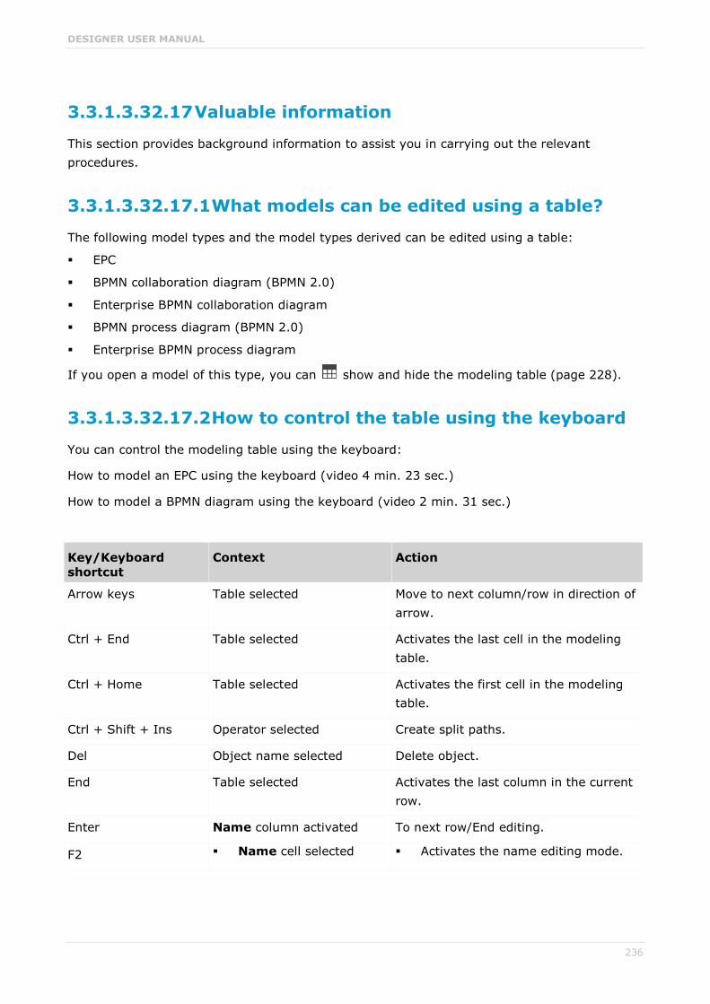
DESIGNER USER MANUAL
236
3.3.1.3.32.17 Valuable information
This section provides background information to assist you in carrying out the relevant procedures.
3.3.1.3.32.17.1 What models can be edited using a table?
The following model types and the model types derived can be edited using a table:
EPC
BPMN collaboration diagram (BPMN 2.0)
Enterprise BPMN collaboration diagram
BPMN process diagram (BPMN 2.0)
Enterprise BPMN process diagram
If you open a model of this type, you can show and hide the modeling table (page 228).
3.3.1.3.32.17.2 How to control the table using the keyboard
You can control the modeling table using the keyboard:
How to model an EPC using the keyboard (video 4 min. 23 sec.)
How to model a BPMN diagram using the keyboard (video 2 min. 31 sec.)
Key/Keyboard shortcut
Context Action
Arrow keys Table selected Move to next column/row in direction of arrow.
Ctrl + End Table selected Activates the last cell in the modeling table.
Ctrl + Home Table selected Activates the first cell in the modeling table.
Ctrl + Shift + Ins Operator selected Create split paths.
Del Object name selected Delete object.
End Table selected Activates the last column in the current row.
Enter Name column activated To next row/End editing.
F2 Name cell selected Activates the name editing mode.

DESIGNER USER MANUAL
237
Key/Keyboard shortcut
Context Action
Description/Definition cell selected
Opens the Description/Definition dialog. The description/definition can be edited.
Object cell selected Opens the object symbols list if symbols can be inserted.
Attribute cell selected Opens the Edit attribute dialog for you to insert the attribute value.
Home Table selected Activates the first column in the current row.
Ins Table selected Adds an object row.
PageDown Table selected Scrolls one page down.
PageUp Table selected Scrolls one page up.
Shift + F2 BPMN container cell Enables renaming of the container.
Tab Table cell selected Activates the cell to the right of the cell currently selected.
Shift + Tab Table cell selected Activates the cell to the left of the cell currently selected.
3.3.1.3.32.17.3 What do different colors mean in table-based modeling?
The colors help you to distinguish between the object types. They correspond to the object colors.
A flashing cursor in an empty row indicates that entries can be made.
A gray background indicates that no entries can be specified.
Examples A table for a model of the EPC type contains, e.g., green highlighting for functions because
functions are displayed in green in the model. In a table for a BPMN diagram, a task appears in blue, as in the diagram.

DESIGNER USER MANUAL
238
Split paths are outlined by a thicker line.
In BPMN models, lanes are outlined by a thicker line.

DESIGNER USER MANUAL
239
3.3.1.3.32.17.4 What default columns are available?
There are columns that are displayed by default when the modeling table is opened for the first time. However, you can hide all of them except for the numbering, color, and name column. Your setting is saved, which means that when you create or open a model, the table is displayed with the columns you specify.
IN AN EPC
Numbering
Shows the line number.
Color column
Displays the color of the object symbol.
Name
The object name is entered here.
Description/Definition
A description or definition of the object is entered here.
is carried out by Role
The performing role or job description for the object is entered here. If the role or job description are not suitable for this object, a message is displayed.
is support by Application system type
An application system type is inserted here. If such an object is not permitted for an object, e.g., for an event, a message is displayed.
receives input from Information carrier
An information carrier is inserted here. If such an object is not permitted for an object, e.g., for an event, a message is displayed.
creates output to Information carrier
An information carrier is inserted here. If such an object is not permitted for an object, e.g., for an event, a message is displayed.
IN A BPMN DIAGRAM
Numbering
Shows the line number.
Color column
Displays the color of the object symbol.
Name
The object name is entered here.
Description/Definition
A description or definition of the object is entered here.

DESIGNER USER MANUAL
240
Belongs to container
Shows the pool or lane to which an object belongs. This column cannot be edited.
3.3.1.3.32.17.5 What are the special features of BPMN diagrams?
For BPMN diagrams, you can specify whether or not the Belongs to container column is displayed. This column exists only in BPMN diagrams and is displayed by default. Lanes are automatically enlarged in table-based modeling if a new object does not fit completely into the lane.
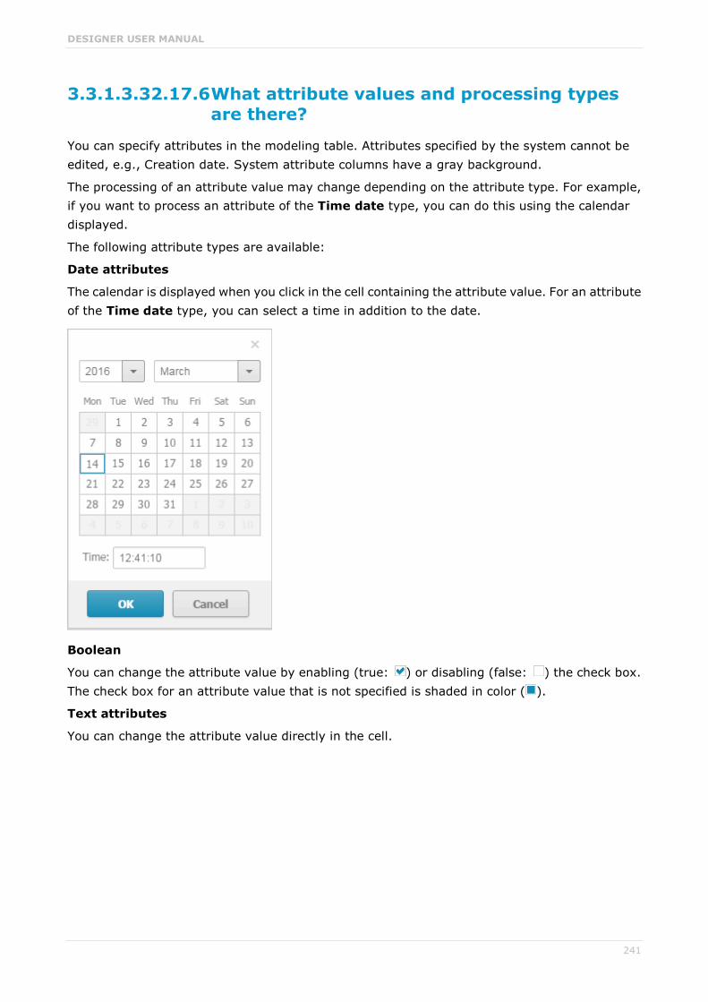
DESIGNER USER MANUAL
241
3.3.1.3.32.17.6 What attribute values and processing types are there?
You can specify attributes in the modeling table. Attributes specified by the system cannot be edited, e.g., Creation date. System attribute columns have a gray background.
The processing of an attribute value may change depending on the attribute type. For example, if you want to process an attribute of the Time date type, you can do this using the calendar displayed.
The following attribute types are available:
Date attributes
The calendar is displayed when you click in the cell containing the attribute value. For an attribute of the Time date type, you can select a time in addition to the date.
Boolean
You can change the attribute value by enabling (true: ) or disabling (false: ) the check box. The check box for an attribute value that is not specified is shaded in color ( ).
Text attributes
You can change the attribute value directly in the cell.

DESIGNER USER MANUAL
242
Formatable text attributes
A dialog opens. You can edit the text and formatting.
Attribute values with unit
A dialog opens. When saving the attribute value for numerical attributes, a check is made as to whether the value entered is a number. If not, you are notified.
Numerical attributes
You can change the attribute value directly in the cell. When saving the attribute value, a check is made as to whether the value entered is a number. If not, you are notified.
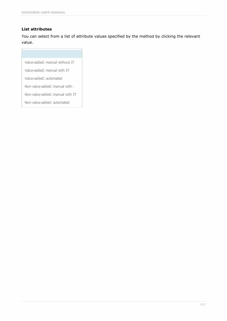
DESIGNER USER MANUAL
243
List attributes
You can select from a list of attribute values specified by the method by clicking the relevant value.

DESIGNER USER MANUAL
244
3.3.1.4 Extended editing
Besides the basic editing options, Model Editor provides you with additional functionality, such as copying formatting (page 251), creating groupings (page 261), applying various colors (page 252), inserting user-defined descriptions (page 249), or automatic resizing of objects (page 262).
3.3.1.4.1 Find objects in an open model
You can have objects selected in the model window. If the object is not located in the visible area of the model window the visible area is moved and the object is displayed as selected in the visible area.
Procedure
1. Click the Find bar button. The Find bar opens.
2. Enter a part of the name or the entire name for the object to be found.
3. Click either Search down or Search up, depending on the direction in which you want to search for objects. The next object whose name contains the term entered is selected. If it is located outside of the visible area it is placed in the visible area.
4. Click Search down or Search up again. The next object with the term in its name is selected.
Each time you click the up and down buttons the next occurrence is selected. If a corresponding object cannot be found in the one direction the first occurrence is selected again.

DESIGNER USER MANUAL
245
3.3.1.4.2 Show where object occurrences are used
You can display where occurrences of an object are used and select the required occurrence using the navigation controls.
Procedure
1. Select an object in the model.
2. Click Properties. The Properties bar opens.
3. Click the Occurrences tab. The occurrences of the selected object are listed. If more than one occurrence exists in the current model, the number of the selected occurrence and the total number of occurrences are displayed next to the object name.
4. Click the left or right arrow to navigate to the next occurrence in the model. The next occurrence is selected and its number updated.
5. To directly select an occurrence, expand the drop-down list and click the occurrence number.
6. To open a model that contains an occurrence of the selected object, click the name of the model in the In other models area. The model opens and the first occurrence of the object is selected. If there is no diagram view for the occurrence, the first fact sheet tab is shown, e.g., Overview.
In the In other models area, all models are displayed to which you have at least read access.
You switched between the occurrences of an object using the navigation controls.
3.3.1.4.3 Place an object in an object
You can place an object in another object. The object then overlaps the object in which it is placed and has an implicit connection to this object. Implicit connections are connections that are not being displayed while an object is placed in another object.
Procedure
1. Click the object you want to place in another object, and hold down the mouse button.
2. Drag the object on top of the other object, position it inside the other object's borders, and release the mouse button. If multiple connections are available between the two objects, the connection selection is displayed. A right arrow is added to the outgoing connections of the embedded object, while a left arrow is added to the incoming connections.
3. Click the connection you want to draw between these two objects. The connection created is an implicit connection, which means that it is not displayed while the object is embedded in the other object.
The object is now placed in the other object. Due to the existing implicit connection, the embedded object is also selected or moved when the object in which it was placed is selected or moved.
Tip
You can place multiple objects of one type in an object at once.

DESIGNER USER MANUAL
246
3.3.1.4.4 Place an object on an object
You can place an object on another object. The object then overlaps the object on which it is placed, but has no implicit connection to this object. Implicit connections are connections that are not being displayed while an object is placed in another object.
Procedure
1. Click the object you want to place on another object, and hold down the mouse button.
2. Drag the object on top of the other object, position it inside the other object's borders, and release the mouse button. The connection selection is displayed.
3. Click No connection. Thus, no connection is created between the two objects.
The object is now placed on the other object. Due to the lack of an implicit connection, the embedded object is neither selected nor moved when the object on which it was placed is selected or moved.
3.3.1.4.5 Upload documents
You can upload documents to ARIS document storage and assign them to models and objects (page 247) in order to supplement these with detailed descriptions and graphics, for example.
Prerequisite
The filter in use allows the ARIS document storage Link attribute.
Procedure
1. Open (page 212) the relevant model.
2. Activate (page 208) the Properties bar.
3. Activate the Attributes tab if it is not activated yet.
4. Show the ARIS document storage Link attribute.
5. In the editing cell of the ARIS document storage Link attribute, click Edit. The Select document dialog opens.
6. Select ARIS document storage if it is not yet selected.
7. Select the folder in which you want to save the document.
8. Click Upload new document. The dialog opens.
9. Click Browse. The dialog opens.
10. Navigate to the relevant document, select it, and click Open.
11. The dialog closes and you may enter the document's title, a description, as well as tags (keywords) enabling the document to be identified in ARIS document storage.
12. Click Upload.
Once the upload of the document is complete, you can assign it to models and objects (page 247).
DESIGNER USER MANUAL
247
3.3.1.4.6 Assign documents
You can supplement individual models and objects with, for example, detailed information and graphics by assigning documents available in ARIS document storage to them.
Prerequisite
The filter in use allows the ARIS document storage Link attribute.
Procedure
1. Open (page 212) the relevant model.
2. Select the object to which you want to assign a document, or ensure that no object is selected if you want to assign the document to the model.
3. Activate the Properties bar.
4. Activate the Attributes tab if it is not activated yet.
5. Show (page 208) the ARIS document storage Link attribute.
6. In the editing cell of the ARIS document storage Link attribute, click Edit. The Select document dialog opens.
7. Select ARIS document storage if it is not yet selected.
8. Select the folder containing the relevant document.
9. Enable the option button of the document you want to assign.
10. Click OK.
The document is assigned to the item.
On the Documents tab, a document with the ARIS document storage Link attribute is marked
with for objects and for models. If a document title was specified, it is shown, otherwise the complete link to the document in ARIS document storage. You can place the attribute (page 255). To ensure that the name you specify is placed in the model instead of the link, you can show the ARIS document storage Title attribute from the Attributes tab (Properties bar). If you specify a name for the attribute, this name is displayed in the model instead of the contents of the placed ARIS document storage Link attribute.

DESIGNER USER MANUAL
248
3.3.1.4.7 Link documents
You can link documents available in ARIS document storage directly with individual models and objects and thus supplement them with detailed descriptions and graphics, for example.
Procedure
1. Open (page 212) the relevant model.
2. Select the object for which you want to create a link to a document, or ensure that no object is selected if you want to link the document with the model.
3. Click Properties.
4. Activate the Documents bar.
5. Click Add.
6. In ARIS document storage, click the folder containing the relevant document.
7. Enable the check box for the required document, and click OK.
The document is linked with the item.
On the Documents tab, a mark is shown: for objects and for models. If a document title was specified, it is shown, otherwise the complete link in ARIS document storage.

DESIGNER USER MANUAL
249
3.3.1.4.8 Use the Documentation attribute
You can describe database and model items (models, objects, groups, etc.) using formatted documents or other files and save these documents in the Documentation attribute. If you are using the Microsoft® Word file formats DOC and DOCX, a preview is available and the Edit button is available. You can also create the documents directly from the Documentation attribute.
Procedure
Insert an external description
Prerequisite
You are using Microsoft® Word.
Procedure
1. Start ARIS Connect and open Model Editor.
2. Select the item to which you want to assign the description and which does not yet have an external description.
3. Activate the Attributes tab of the Properties bar and show the Documentation attribute (page 208).
4. Click Edit in the attribute row. Microsoft® Word opens with a blank document.
5. Enter your description and click Save.
The description is assigned to the item. When you click Edit again, the document opens and you can edit it.
Import external description
1. Create an external description and save it, for example, in Microsoft Word.
2. Start ARIS Connect and open Model Editor.
3. Select the item you want to assign the description to.
4. Activate the Attributes tab of the Properties bar and show the Documentation attribute (page 208).
5. Click Import in the attribute row. The Select document dialog opens.
6. Click Select file and select the newly created external description in the dialog.
7. Click Open.
The document is inserted in the Documentation attribute.

DESIGNER USER MANUAL
250
Edit an external description
If you are using the Microsoft® Word file formats DOC and DOCX, a preview is available and the Edit button is available.
Warning
Due to technical restrictions external descriptions cannot be locked if they are open in the editor. Therefore, it is possible that a user deletes an external description in ARIS Connect while it is being edited by another user in the text editor. In this case, all changes of the description are deleted without the editing user being notified.
Procedure
1. If the attribute is not displayed: Activate the Attributes tab of the Properties bar and show the Documentation attribute (page 208).
2. Click Edit in the attribute row. The word processor is launched and the document opens.
3. Edit and save the document.
4. Close Microsoft® Word and activate ARIS Connect.
5. If necessary, click Update.
The document is added to the Documentation attribute and a preview is displayed.
Display external descriptions read-only
1. Select the item the description of which you want to display.
2. Activate the Attributes tab of the Properties bar and show the Documentation attribute (page 208).
3. Click Display. Depending on your browser, you may be asked whether you want to save or open the file.
4. Select Open. The corresponding program launches and the file opens in read-only mode.
You can now find out about the content of the document.
If you decide to save the document, you must save it with a name that differs from its previous name. Thus, a copy is created. It is, however, not inserted into the Documentation attribute.
Refresh the preview of the external description
1. Select the item the description of which you want to display.
2. Activate the Attributes tab of the Properties bar and show the Documentation attribute (page 208).
3. Click Refresh.
The display of the Documentation attribute is updated so that the changes you have made will be displayed.
You have described a database or model item with a formatted document.

DESIGNER USER MANUAL
251
3.3.1.4.9 Format painter
You can copy the formats of a selected item to another item or to several other items. This way, you can transfer the format of one object to all other objects and need not to transfer it to each object individually.
Procedure
1. Select the model item whose format you want to copy.
2. Activate the Start (page 275) tab bar.
3. Click Format painter.
4. If you want to copy the format to one item: click the relevant item. If you want to copy the format to more than one item: use the mouse to draw a border around the relevant items. You can also press the Ctrl key and click the required items one after the other.
The format of the selected items is adjusted accordingly.
3.3.1.4.10 Color model items
You can assign a different color to object symbols and graphic objects.
Procedure
1. Select the model items you want to color.
2. Activate the Start (page 275) tab bar.
3. Click Fill color. The color palette opens.
4. Click the color you want to color the selected model item with. The selected model items are colored with the selected color. The color palette closes.
You have colored the selected model items.
DESIGNER USER MANUAL
252
3.3.1.4.11 Color model items with a user-defined color
You can assign your own color to object symbols and graphic objects.
Procedure
1. Select the model items you want to color.
2. Activate the Start (page 275) tab bar.
3. Click Fill color. The color palette opens.
4. Click Choose your own color. The Define color dialog opens.
5. Select your own color in one of the ways described below. Your changes will be displayed in the preview window on the right:
a. Click the color bar and move the line to the relevant color range to select the basic color. Then click on the relevant position in the color box to select the brightness of the basic color.
b. Enter the respective share of each color from 0 to 255 in the Red, Green and Blue boxes. 0 means that the corresponding color is absent. If you enter 0 in all three boxes you have selected the color black.
c. Enter a hexadecimal color definition in the Color code: # box. The hexadecimal system uses the letters A to F in addition to the numerals of the decimal system, which means that it is based on the base 16. If you enter FFFF00, this sets the color to Yellow.
6. Click OK.
You have colored the selected model items with a self-defined color.
3.3.1.4.12 Color model items with a gradient
You can color object symbols and graphic objects with a gradient.
Procedure
1. Select the model items you want to color.
2. Activate the Start (page 275) tab bar.
3. Click Fill color. The color palette opens.
4. Click Choose your own color. The Define color dialog opens.
5. Enable the Gradient check box. Two color boxes and a list box for the direction of the gradient are displayed.
6. Click the first color box and select the start color (page 252) for the gradient.
7. Click the second color box and select the second color (page 252) for the gradient.
8. Click the list box and select the direction of the gradient.
9. Click OK.
You have colored the selected model items with a gradient.

DESIGNER USER MANUAL
253
3.3.1.4.13 Display model items without color
You can display object symbols and graphic objects without a color fill.
Procedure
1. Select the model items you want to display without color.
2. Activate the Start (page 275) tab bar.
3. Click Fill color. The color palette opens.
4. Click No fill color.
The selected model items are displayed without color.
3.3.1.4.14 Reset object symbol color
You can reset the color of an object symbol back to the default color if you have changed the color.
Procedure
1. Select the object symbol you colored.
2. Activate the Start (page 275) tab bar.
3. Click Fill color. The color palette opens.
4. Click Reset.
You have reset the color of the selected object symbols to their original color.
3.3.1.4.15 Color borders and lines
You can assign a different color to the borders of object symbols and graphic objects, as well as connections.
Procedure
1. Select the model items whose borders you want to color.
2. Activate the Start (page 275) tab bar.
3. Click Line color. The color palette opens.
4. Click the color you want to color the borders and lines of the selected model items with.
You have colored the borders and lines of the selected model items.

DESIGNER USER MANUAL
254
3.3.1.4.16 Reset border and line color
You can reset the colors of the borders and lines of model items if you changed their color.
Procedure
1. Select the model items whose borders or lines you colored.
2. Activate the Start (page 275) tab bar.
3. Click Line color. The color palette opens.
4. Click Reset.
You have reset the colors of the borders and lines of selected model items.
3.3.1.4.17 Change line style
You can assign a different style to the borders of object symbols, graphic objects, and connections.
Procedure
1. Select the model items whose border and line style you want to change.
2. Activate the Start (page 275) tab bar.
3. Click Line style and weight. The style selection opens.
4. Click Dotted, Dashed, or Solid, depending on which style you want to assign to the selected elements.
The style of the borders and lines of the selected model items is adjusted accordingly.
3.3.1.4.18 Change line weight
You can change the weight of the borders of object symbols, graphic objects, and connections.
Procedure
1. Select the model items whose line weight for borders and lines you want to change.
2. Activate the Start (page 275) tab bar.
3. Click Line style and weight. The weight selection opens.
4. Click 0 point, 2 point, 4 point, or 8 point, depending on which weight you want to assign to the borders and lines of the selected model items.
The weight of the borders and lines of the selected model items is adjusted accordingly.

DESIGNER USER MANUAL
255
3.3.1.4.19 Change item appearance
You can change the appearance of model items in the model window.
Procedure
1. Select the model items whose appearance you want to define.
2. Activate the Start (page 275) tab bar.
3. Click Appearance. The appearance selection opens.
4. Click Shaded if the selected items are to have a shadow. The check box is enabled. Connections cannot have a shadow.
5. Click 3-D effect if the selected items are to be displayed in 3-D style. The check box is enabled. Connections cannot be displayed in a 3-D style.
6. Click Active if the selected items are to be displayed as inactive. The check box is disabled. Objects are displayed without color and with a gray border, connections are displayed in gray. Graphic objects cannot be displayed as inactive.
You have defined the appearance of model items. To change a setting again, click the relevant option again.
3.3.1.4.20 Place attributes at fixed positions
You can place any attribute of objects and connections, not just the name, visibly in the model window. For quick placement several fixed positions in and around the object are offered.
Procedure
Place new attributes at fixed positions
1. Select the object you want to place a new attribute for.
2. Activate the Start (page 275) tab bar.
3. Click Attribute placement.
4. Click Create attribute placement. The Select attribute dialog opens.
5. Enable the Show specified attributes only checkbox. Then only the attributes with a value are made available for selection.
6. Enter the first letters of the required attribute name. All attributes are displayed whose names contain the term you entered.
7. Click the name of the attribute you want to place.
8. Click OK. The dialog closes and a frame for the attribute is displayed in the model window.
9. Click anywhere in the model window.
10. Click the newly placed attribute so that the handles are colored.
11. Click Attribute placement.
12. Click the position of the object where the attribute is to be placed, e.g., Top right.
DESIGNER USER MANUAL
256
The attribute is placed in the selected position at the object. You can specify that the attribute name is to be displayed for the placed attribute. You can also specify for certain attributes that they are to be displayed as a symbol.
Place freely placed attributes at fixed positions
1. Select the freely placed attributes you want to place at a fixed position. Their handles will be colored.
2. Activate the Start (page 275) tab bar.
3. Click Attribute placement.
4. Click the position of the object where the attribute is to be placed, e.g., Top right.
The attributes are placed at the objects at the position selected. You can specify that the attribute name is to be displayed for placed attributes. You can also specify for certain attributes that they are to be displayed as a symbol.
You have placed attributes at fixed positions.
3.3.1.4.21 Place attributes at any position
You can place any attribute of objects and connections, not just the name, visibly in the model window. These cannot only be placed at fixed positions (page 255), but also freely.
Procedure
Place new attribute freely
Select the object you want to place a new attribute for.
1. Activate the Start (page 275) tab bar.
2. Click Attribute placement.
3. Click Create attribute placement. The Select attribute dialog opens.
4. Enable the Show specified attributes only checkbox. Then only the attributes with a value are made available for selection.
5. Enter the first letters of the attribute name. All attributes are displayed whose names contain the term you entered.
6. Click the name of the attribute you want to place.
7. Click OK. The dialog closes and a frame for the attribute is displayed in the model window.
8. In the model window, click the position where you want to place the attribute.
The attribute is placed in the selected position in the model window.
Reposition a placed attribute
1. Click the placed attribute you want to reposition. The handles will be colored.
2. Hold down the mouse button.
3. Drag the attribute to the position in the model window where you want to place it and release the mouse button.
DESIGNER USER MANUAL
257
The attribute is placed in the selected position in the model window.
You have placed attributes at any positions.
3.3.1.4.22 Place attributes from Attributes tab
Use the Attributes tab to quickly place an attribute.
Procedure
1. Select the object you want to place a new attribute for.
2. Click Properties. The Properties bar opens.
3. Click the Attributes tab if it is not activated yet.
4. Behind the attribute you want to place, click More.
5. Click Place attribute.
6. Move the mouse pointer to the model window. A frame is displayed.
7. Drag the frame in the model window to the position where you want to place the attribute.
8. Click the relevant position.
The attribute is placed.
3.3.1.4.23 Display names of placed attributes
You can specify that the attribute name of placed attributes is to be displayed in the model window.
Procedure
1. Select the placed attribute whose attribute name you want to display in the model window.
2. Activate the Start (page 275) tab bar.
3. Click Attribute placement.
4. Enable the With name check box.
The attribute value is placed in front of the attribute name.
3.3.1.4.24 Select placed attributes
You can select placed attributes in order to place them at another position or to remove the placement (page 259).
Procedure
1. Click a placed attribute in the model window. The attribute is marked by a colored handle.
2. Press the Ctrl key, and click additional placed attributes you want to reposition or remove.
You can now delete or reposition (page 255) the selected attributes.
DESIGNER USER MANUAL
258
3.3.1.4.25 Edit placed attributes
You can edit placed text attributes of models, objects, and connections in the model window. You cannot change or delete attribute values of attributes that the system defines. These are placed in gray cells, for example, Last change.
Procedure
1. Click the placed attribute. It now has handles.
2. Click on the text attribute again. The attribute is selected for editing.
3. Change the text attribute as necessary.
4. Press the Enter key or click in the model background.
The text attribute is changed.
3.3.1.4.26 Directly format placed attributes
You can format model, object, and connection attributes when editing in the model window.
Prerequisite
The attribute you selected can be edited. You cannot change or delete attribute values of attributes that the system defines. These are placed in gray cells, for example, Last change.
Procedure
1. Double-click the placed attribute of a model, object, or connection so that the text is selected. The formatting toolbar is shown.
2. In the formatting toolbar, click the button for the formatting you want to assign to the
selected attribute, e.g., Increase indent. The formatting information is directly applied to the selected attribute.
3. Click an empty area in the model window. The attribute selection is undone.
You have formatted the placed attribute.
3.3.1.4.27 Move placed attribute
You can move placed attributes of objects and connections.
Procedure
1. Click the placed attribute and hold down the mouse button. The attribute now has handles.
2. Drag the attribute to the required position and release the mouse button.
The attribute is placed at the new position.

DESIGNER USER MANUAL
259
3.3.1.4.28 Display placed attributes as a symbol
You can display certain attributes as a symbol (page 280) if they are placed.
Prerequisite
The attribute can be represented by a symbol. This is the case if you select the attribute and the As a symbol check box becomes available.
Procedure
1. Select the placed attribute you want to represent with a symbol.
2. Activate the Start (page 275) tab bar.
3. Click Attribute placement.
4. Enable the As a symbol check box.
The placed attribute is represented as a symbol.
3.3.1.4.29 Remove placed attribute
You can remove placed attributes from the model window. Of course, only the attribute placement is deleted and not the value that was placed. To change the attribute value, edit the
attribute (page 221) on the Attributes tab of the Properties bar.
Procedure
1. Select the placed attribute (page 257) whose placement you want to remove.
2. Press the Del key.
The placement of the selected attribute is removed without prompting for confirmation.
3.3.1.4.30 Remove multiple placed attributes
You can remove multiple placed model, object, or connection attributes from the model window in only one step. Of course, only the attribute placement is deleted and not the value that was placed.
Procedure
Remove directly
1. Use the Ctrl key to select the placed attributes you want to delete in the model window directly.
2. Press the Del key.
The placements of the selected attributes are removed without prompting for confirmation.
Use a dialog
1. Select the object or connection whose attribute placements you want to remove.
2. Activate the Start (page 275) tab bar.
3. Click Attribute placement > Delete attribute placement. The dialog is displayed.
DESIGNER USER MANUAL
260
4. Enable the check boxes for the placed attributes whose attribute placement you want to delete. You can enable all check boxes at once by enabling the superior check box Attribute name.
5. Click OK.
The placements of the selected attributes are removed without prompting for confirmation.
You have removed multiple placed attributes.
3.3.1.4.31 Assign a model to an object
You can assign models to objects. The assignment enables you to describe objects in independent models in more detail, for example. Assigned models are displayed by way of an assignment icon at the object and can be opened by double-clicking the assignment icon.
Procedure
1. In the open model, click the object to which you want to assign a new model.
2. Activate the Start (page 275) tab bar.
3. Click Assignment > Create assignment. The dialog opens.
4. Select the required model type. The model types that are allowed for the selected object by the method and by the method filter in use are available for selection.
5. Enter the relevant model name. The name of the selected object is suggested as a model name.
6. Click OK.
The new model is assigned to the selected object and opens on a separate tab. You can model the required content.
3.3.1.4.32 Place model items one behind the other
You can specify in which order overlappping model items are placed one behind the other in the model window.
In the example below, it is assumed that you have created the three objects 1, 2, and 3 in sequence. As the most recently placed objects are created at the highest level, object 3 is at the highest level and object 1 is at the lowest level. You want to reverse this sequence.
Procedure
1. Activate the Start (page 275) tab bar.
2. Select the object 3 and click Arrange > Send backward.
3. Select the object 1 and click Arrange > Bring forward.
Now, when you place the objects one behind the other they are placed in the order 1, 2, and 3.
In the same manner, you can place graphic objects such as squares or circles behind parts of objects to highlight these areas separately.
DESIGNER USER MANUAL
261
3.3.1.4.33 Group model items
You can group model items and then handle them as if they were a single object.
Procedure
1. Select the model items you want to group.
2. Activate the Start (page 275) tab bar.
3. Click Group/Ungroup > Group. The selected model items are combined in a group (page 308). The handles are placed around the grouping.
To select all items in a group, click one of the previously independent items. You can now move them all together, for example.
3.3.1.4.34 Ungroup
You can undo the grouping of model items and move and edit the items of the group separately once again.
Procedure
1. Select the grouping you want to undo.
2. Activate the Start (page 275) tab bar.
3. Click Group/Ungroup > Ungroup. The grouping is ungrouped. Each item has its own handles.
When you click one of the previously grouped items, it is now selected separately once again and can be moved separately.
3.3.1.4.35 Align model items
You can quickly align selected model items relative to each other.
Procedure
1. Select the model items you want to align.
2. Activate the Start (page 275) tab bar.
3. Click Align and then the relevant alignment, for example Align left or Distribute vertically.
The selected model items are aligned accordingly.

DESIGNER USER MANUAL
262
3.3.1.4.36 Match size of items
You can resize selected items so that they match.
Procedure
1. Select the different-sized model items you want to match.
2. Activate the Start (page 275) tab bar.
3. Click Match size of items and then the relevant size change, for example, Same height (maximum).
The height of the selected model items is matched to that of the tallest item.
3.3.1.4.37 Select object or model in Explorer
You can navigate from a model to the occurrence of a selected object or of the model in Explorer.
Prerequisite
Selected objects are saved.
Procedure
1. Select the object to whose occurrence you want to navigate to in Explorer. If you want to navigate to the occurrence of the model, make sure that no object is selected.
2. Activate the Start (page 275) tab bar.
3. Click Go to occurrence in Explorer.
A new tab showing the repository opens. The group structure of the database expands and the check box in front of the selected object or model is enabled in the detail view.
3.3.1.4.38 Map Alfabet objects to ARIS objects
You can map an Alfabet object to an ARIS object. Multiple mapping is not possible. By default, objects of the Application system type type can be mapped. In the description, this object type is used as an example.
Prerequisite
The database is connected with Alfabet.
Procedure
1. Open a model that contains objects of the Application system type type.
2. Select the relevant application system type.
3. In the Start (page 275) tab bar, click Alfabet > Map Alfabet object. The Select Alfabet object dialog opens.
4. Select the Alfabet table, e.g., Application. You will see only those Alfabet objects you have the privileges to use. If you start typing the object name into the Filter field, the number of entries will decrease.
5. Click the Alfabet object you want to map to the ARIS object. The option button is activated.

DESIGNER USER MANUAL
263
6. Click OK.
The mapping between the Alfabet object and the ARIS object has been created. The name of the Alfabet object is now used for the ARIS object. Additional attributes have been entered for this object in the Alfabet attribute type group in ARIS.
3.3.2 Create Alfabet object
You can create a missing Alfabet object to be mapped to an ARIS object.
Prerequisite
The database is connected with Alfabet.
Procedure
1. Open a model that contains objects of the Application system type type.
2. Select the relevant application system type.
3. In the Start (page 275) tab bar, click Alfabet > Map Alfabet object. The Select Alfabet object dialog opens.
4. Select the Alfabet table, e.g., Application.
5. Click Create Alfabet object button. The Alfabet login dialog opens.
6. Create the object in Alfabet.
7. In the Select Alfabet object dialog of the Model Editor, click Refresh.
The new object is listed in the table.
3.3.2.1.1 Unmap Alfabet object
You can delete the mapping between an ARIS object and an Alfabet object. By default, objects of the Application system type type can be mapped. In the description, this object type is used as an example.
Prerequisite
The database is connected with Alfabet.
Procedure
1. Open a model that contains objects that are mapped to Alfabet objects (page 262).
2. Select the relevant Application system type object.
3. In the Start (page 275) tab bar, click Alfabet > Unmap Alfabet object.
The mapping between the selected ARIS object and the Alfabet object is removed without prompting. All attributes in the Alfabet attribute type group are deleted. The name of the Alfabet object continues to be used for the ARIS object.
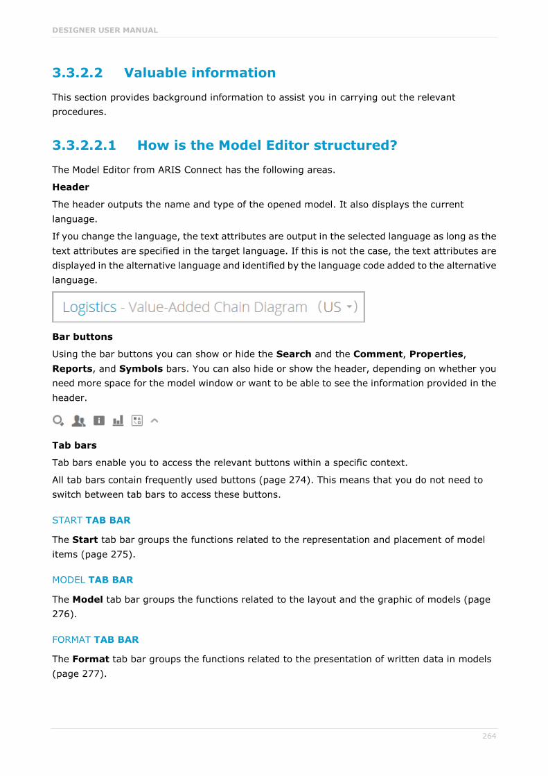
DESIGNER USER MANUAL
264
3.3.2.2 Valuable information
This section provides background information to assist you in carrying out the relevant procedures.
3.3.2.2.1 How is the Model Editor structured?
The Model Editor from ARIS Connect has the following areas.
Header
The header outputs the name and type of the opened model. It also displays the current language.
If you change the language, the text attributes are output in the selected language as long as the text attributes are specified in the target language. If this is not the case, the text attributes are displayed in the alternative language and identified by the language code added to the alternative language.
Bar buttons
Using the bar buttons you can show or hide the Search and the Comment, Properties, Reports, and Symbols bars. You can also hide or show the header, depending on whether you need more space for the model window or want to be able to see the information provided in the header.
Tab bars
Tab bars enable you to access the relevant buttons within a specific context.
All tab bars contain frequently used buttons (page 274). This means that you do not need to switch between tab bars to access these buttons.
START TAB BAR
The Start tab bar groups the functions related to the representation and placement of model items (page 275).
MODEL TAB BAR
The Model tab bar groups the functions related to the layout and the graphic of models (page 276).
FORMAT TAB BAR
The Format tab bar groups the functions related to the presentation of written data in models (page 277).
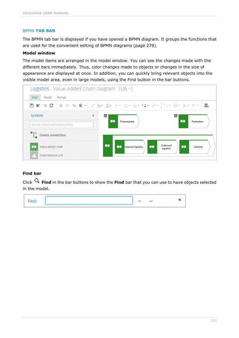
DESIGNER USER MANUAL
265
BPMN TAB BAR
The BPMN tab bar is displayed if you have opened a BPMN diagram. It groups the functions that are used for the convenient editing of BPMN diagrams (page 278).
Model window
The model items are arranged in the model window. You can see the changes made with the different bars immediately. Thus, color changes made to objects or changes in the size of appearance are displayed at once. In addition, you can quickly bring relevant objects into the visible model area, even in large models, using the Find button in the bar buttons.
Find bar
Click Find in the bar buttons to show the Find bar that you can use to have objects selected in the model.

DESIGNER USER MANUAL
266
Symbols bar
The Symbols bar provides object symbols (page 214), graphic objects (page 218), and text (page 223) for insertion into the model window. It also allows you to filter the available object symbols by entering names and create connections between (page 222) objects.
Properties bar
Click Properties in the bar buttons to show the Properties bar where you can edit attributes (page 221), or view occurrences and relationships of objects, for example.

DESIGNER USER MANUAL
267
Comment bar
Click Comment in the bar buttons to show the Comment bar that you can use to enter notes, improvement proposals, questions, etc., pertaining to the model.
Reports bar
Click Reports in the bar buttons to show the Reports bar and generate reports.

DESIGNER USER MANUAL
268
Display bar
The Display bar is located at the bottom of the model window. You can use this bar to quickly define which model areas are to be displayed in the visible window pane.
If for example, you want to display the entire model in the visible window pane, click Fit to window (without any model item being selected).

DESIGNER USER MANUAL
269
3.3.2.2.2 What model types are available in ARIS Connect?
The following model types are available. Depending on the filter you are using not all model types are available.
Access diagram
Access diagram (physical)
Application collaboration diagram
Application collaboration diagram (physical)
Application system diagram
Application system type diagram
ArchiMate model
Attribute allocation diagram (Solution Design)
BPMN allocation diagram (BPMN 2.0)
BPMN collaboration diagram (BPMN 2.0)
BPMN conversation diagram (BPMN 2.0)
BPMN process diagram (BPMN 2.0)
BSC Cause-and-effect diagram
Bow tie diagram
Business controls diagram
Business footprint diagram
Business rule allocation diagram
Business rule architecture diagram
Business segment matrix
Class diagram
CtX-tree
Data type diagram (Solution Design)
Data Warehouse model
Document structure (Solution Design)
DW structure
eERM
eERM attribute allocation diagram

DESIGNER USER MANUAL
270
Enterprise BPMN collaboration diagram
Enterprise BPMN process diagram
EPC
EPC (column display)
EPC (horizontal table display)
EPC (material flow)
EPC (row display)
EPC (table display)
Fishbone diagram
Function allocation diagram
Function mapping
Functions mapping (SAP Solution Manager)
Function tree
IE Data model
Information carrier diagram
IT architecture mapping
IT architecture matrix
Knowledge map
Knowledge structure diagram
KPI allocation diagram
KPI tree
Network diagram
Network topology
Objective diagram
Organizational chart
Process selection diagram
Process selection matrix
Product allocation diagram
Product selection matrix
Product/Service exchange diagram
Product/Service tree

DESIGNER USER MANUAL
271
Product tree
Program flow chart
Questionnaire template allocations
Quick model
RAD
Requirement allocation diagram
Requirements tree
Risk diagram
Role diagram
SAP functions mapping (SAP Solution Manager)
SAP NetWeaver Business Warehouse data flow model
SAP NetWeaver Business Warehouse data flow model
SAP NetWeaver Business Warehouse mapping multi provider
SAP NetWeaver Business Warehouse structure
SAP NetWeaver Business Warehouse transformation
SAP Solutions allocation diagram
SAP Solutions organizational elements mapping
Screen design
Screen design (Solution Design)
Screen diagram
Screen navigation
Service allocation diagram
Service architecture diagram
Service collaboration diagram
SIPOC
Strategy allocation diagram
Strategy diagram
Structuring model
Survey management
SWOT diagram
System environment

DESIGNER USER MANUAL
272
Table diagram
Task allocation diagram
Technical resources
Technical terms model
TOGAF diagram
Value-added chain diagram
Value stream map
Work breakdown structure
XML model
3.3.2.2.3 Which method filter is used?
When you open and edit models, your work is based on method filters (page 311).
The method filter applied depends on the method filter(s) assigned to you.
If you were assigned only one filter, that filter is applied.
If you were assigned multiple filters:
The method filter assigned to the database is used (default filter of the database).
If the default filter of the database does not exist, the filter Entire method is used.
If the Entire method filter also does not exist, the first method filter of the alphabetically sorted list is used.
Database administrators specify which method filter a user may use in ARIS Cloud. To do this, a database administrator assigns the relevant method filter to the database and user in ARIS Cloud Administration.

DESIGNER USER MANUAL
273
3.3.2.2.4 What are tab bars for?
Tab bars enable you to access the relevant buttons within a specific context.
All tab bars contain frequently used buttons (page 274). This means that you do not need to switch between tab bars to access these buttons.
START TAB BAR
The Start tab bar groups the functions related to the representation and placement of model items (page 275).
MODEL TAB BAR
The Model tab bar groups the functions related to the layout and the graphic of models (page 276).
FORMAT TAB BAR
The Format tab bar groups the functions related to the presentation of written data in models (page 277).
BPMN TAB BAR
The BPMN tab bar is displayed if you have opened a BPMN diagram. It groups the functions that are used for the convenient editing of BPMN diagrams (page 278).
DESIGNER USER MANUAL
274
3.3.2.2.5 What general buttons are available?
The following general buttons are available for each tab bar.
Save: Saves your changes in the database.
Undo: Undoes editing steps.
Redo: Redoes editing steps that were undone.
Refresh: Refreshes the display. Reloads the data from the database and thereby also shows any changes made by a different editor in the meantime.
Delete: Deletes selected model items.
Cut: Cuts selected items and saves them to the clipboard.
Copy. Copies selected items to the clipboard.
Paste: Pastes the content of the clipboard into the model. If an object is on the clipboard, an occurrence copy (page 282) is inserted. Click the arrow next to the Paste icon if you want to paste a definition copy.

DESIGNER USER MANUAL
275
3.3.2.2.6 What buttons does the Start tab bar have?
The Start tab bar provides the following buttons.
Format painter: Transfers the format (page 251) from one item to another.
Fill color: Colors the item in the selected color (page 251).
Line color: Colors the line of the item in the selected color (page 253).
Equation 1: Edit
Line style and weight: Assigns selected items a different style (page 254) (Dotted, Dashed, or Solid) and defines the weight (page 254).
Appearance: Assigns other properties to or removes properties from selected items (page 255), such as Shaded, 3-D effect, and in addition, Active for objects.
Change symbol: Changes the symbol (page 218) of a selected object or the symbols of all selected objects of a type.
Place attribute: Places text attributes at the preset positions.
Assignments: Assigns a new model to the selected object (page 260). The type and name of the new model can be selected.
Arrange: Positions selected items (page 260) behind or in front of other items.
Group/Ungroup: Groups selected items (page 261), so that they can be treated like a single item or ungroups them (page 261).
Align: Aligns selected items on the modeling area with regard to each other (page 261).
Match size of items: Matches the size of selected model items with each other (page 262).

DESIGNER USER MANUAL
276
Go to occurrence in Explorer: Opens a new tab showing the repository for the selected object or model and enables the relevant check box.
Alfabet: Provides functionality for establishing connections (page 262) with Alfabet.
3.3.2.2.7 What buttons does the Model tab bar have?
The Model tab bar provides the following buttons.
Optimize layout: Automatically creates a new layout for the model.
Horizontal space: Inserts space in your model from left to right.
Vertical space: Inserts space in your model from top to bottom.
Export graphic: Exports the graphic of the model to your download area.
Grid: Shows and hides (page 213) the grid in the model windows and sets the grid width (page 214).
Template: Provides the available model templates for selection (page 210).
DESIGNER USER MANUAL
277
3.3.2.2.8 What buttons does the Format tab bar have?
The Format tab bar provides the following buttons.
Format painter: Transfers the format (page 251) from one item to another.
Font format: Provides the available font formats for selection.
Bold: Applies bold formatting to a text.
Italic: Applies italic formatting to a text.
Underline: Applies underline formatting to a text.
Strikethrough: Applies strikethrough formatting to a text.
Font color: Opens the color palette for you to change the color of the selected text.
Font: Provides all fonts available for the selected text.
Font size: Enables you to change the font size for the selected text.
Reset character formatting: Undoes all formatting changes.
Increase indent: Increases the text indent from the left margin.
Decrease indent: Decreases the text indent from the left margin.
Bullets: Applies a bullet to each paragraph of the selected text.
Numbering: Turns the paragraphs of the selected text into a numbered list, starting at 1.
Align left: Aligns selected text to the left.

DESIGNER USER MANUAL
278
Centered: Aligns selected text to the center.
Align right: Aligns selected text to the right.
3.3.2.2.9 What buttons does the BPMN tab bar have?
The BPMN tab bar provides the following buttons.
Change symbol: Changes the symbol (page 218) of a selected object or the symbols of all selected objects of a type.
Add lane: Adds a new lane (page 225) to a pool or lane.
Insert lane: Inserts a selected lane in the selected pool or lane (page 225).
Delete pool or lane: Deletes the selected pool or lane (page 226).
Move lane: Moves the selected lane (page 225) in the required direction.
Transform into call conversation: Transforms communication elements into call conversations (page 226).
Change type of sequence flow: Specifies the type of a sequence flow (page 226).
Collapse subprocess: Collapses a subprocess object (page 227).
Expand subprocess: Expands a subprocess object (page 227).
Figure 1: Edit
Edit: Opens the assigned model contained in the subprocess (page 227) on a separate tab for editing.
Select global reference: Opens the dialog Select global process or task to assign it to a Call activity (page 228).

DESIGNER USER MANUAL
279
3.3.2.2.10 What is the mini toolbar for?
The mini toolbar provides you with exactly the object symbols that can be linked to the selected object using a connection.
When you place an object symbol from the mini toolbar in the model window a connection between the selected object and the new object symbol is created at the same time. In addition, you can use the mini toolbar to create connections to existing objects.
The mini toolbar is configured for each object type. When you click an object, the mini toolbar provides the object symbols you selected for the underlying object type.
3.3.2.2.11 How are object relationships displayed by symbols?
The relationships are identified by the following symbols:
Symbol for relationships for which an occurrence or an implicit connection exists in the current model.
Symbol for assignment relationships (implicit relationships).
Symbol for relationships for which no occurrences exist in the current model and that are not implicit either.
For example, if a connection was created between objects A and B and object B has been deleted, the relationship is displayed when object A is selected.
3.3.2.2.12 What placed attribute does an object have?
If you place an object in the model window, the name of the object is output as an attribute. The name attribute is usually placed within the object. You can place additional attributes of objects in the model window in order to have the relevant information available directly in the model window.
If you want to place more attributes, it is useful to place them near the object to which they belong. It can however occur that in the layout objects are positioned very close to one another making it difficult to say which object a placed attribute belongs to. In addition, it is also possible to place attributes freely. If an attribute was placed farther away from its object it may be difficult to assign the placed attribute after the layout is changed.
By clicking on an object it is given colored handles as a marker and its attributes are given handles that are not colored. This enables you to identify which placed attributes an object has.

DESIGNER USER MANUAL
280
This also applies to placed attributes that do not have an attribute value. They are invisible in the model window until you assign a value to them. If the associated object is selected the "invisible" placed attribute also receives attribute handles.
3.3.2.2.13 What to consider when placing objects in/on objects
You can place objects on other objects (page 246) or in other objects (page 245). The difference between these two procedures is as follows: When placing an object on another object you specify that no implicit connection will be created between the objects. In contrast, when placing an object in another object you specify that an implicit connection is to be created between the objects.
You can place multiple objects of one type in an object at once. If you want to embed two objects at once and object 1 already has a connection to the enclosing object while object 2 has none, proceed as follows when creating connections:
Select the connection that exists between object 1 and the enclosing object: This connection now links both objects to the enclosing object.
Select a connection other than the one that exists between object 1 and the enclosing object: Object 1 is now linked to the enclosing object via two connections - the existing connection and the one you have selected. Object 2 uses the new connection.
Objects that were placed in other objects are also moved when the enclosing object is moved. If an enclosing object is selected, the embedded object is selected as well. This indicates clearly that an object is embedded in another object. In contrast, a non-embedded object is neither selected nor moved when the object on which it was placed is selected or moved.
You can drag an embedded object from an enclosing object to the modeling area. The connections linking the objects are then displayed.
3.3.2.2.14 What does place attribute as a symbol mean?
Attributes of objects can be placed in the model window which allows them to emphasize additional, important aspects in the model.
A symbol can be placed instead of a value for some attributes, which allows the attribute value to be identified immediately.
If such an attribute was specified and placed, e. g., the Existence attribute, the As a symbol check box becomes available. If you enable the check box, a plus sign is placed in the modeling area instead of Yes for the Existence attribute, and a minus sign instead of No.

DESIGNER USER MANUAL
281
3.3.2.2.15 What does place attribute as a symbol mean?
There are attributes for which a default symbol is defined.
If such an attribute was specified and placed, e. g., the Existence attribute, the As a symbol check box becomes available. If you enable the check box, a plus sign is placed in the modeling area instead of Yes for the Existence attribute, and a minus sign instead of No.
Other attributes can be assigned attribute symbols for placement by a user with the Configuration administrator function privilege. This is done on the Administration tab in ARIS Cloud Administration.
3.3.2.2.16 What happens to placed attributes that have no attribute value?
If you place an object in the model window, the name of the object is output as an attribute. The name attribute is usually placed within the object. You can place additional attributes of objects in the model window in order to have the relevant information available directly in the model window. The usual procedure is to place attributes with an attribute value that can be seen directly in the model.
However, it may be useful to place attributes that are assigned a value at a later point in time. If, for example, it was defined that, as a rule, the maximum processing time is to be placed to the upper left of the Function object type this may happen even if the attribute value of this attribute has not been entered for all functions. If the value is entered later it is automatically displayed in the model window.
If a placeholder is to be used to make the placement of attributes without a value visible in the model window, you can define that they are to be placed with an attribute name. In our example, Max. processing time: would then be output for the relevant functions, and a value entered would appear behind the colon.

DESIGNER USER MANUAL
282
3.3.2.2.17 What is the difference between occurrence copy and definition copy?
An occurrence copy is only the copy of a graphical representation of an object. Thus, when you create an occurrence copy, a graphic is created that references the copied object:
When you create a definition copy, an entirely new object is created whose attributes are identical with those of the copied object:
If attributes of an object are changed, this change also applies to the corresponding attributes in all occurrences of the object. This becomes clear when changing the Name attribute:

DESIGNER USER MANUAL
283
3.3.2.2.18 Which items can be copied from one model to another?
You can copy graphic objects, such as circles, free-form texts, graphics, and objects, from one model to another.
However, for an object to be pasted in the target model it has to be allowed there by the method. For example , if you copy functions and organizational units in the source model, only the organizational units will be pasted into a model of the Organizational chart type because functions are not allowed in this model type. The corresponding information is provided by the preview frames of the copied functions, showing as crossed out with an X when they are pasted into the organizational chart.
3.3.2.2.19 Which formats are copied to which items?
You can copy the formats of a selected item to another item or to several other items. This depends on whether the format has been copied to one or more items and also the items between which the format is copied.
THE FOLLOWING FORMATS ARE COPIED:
Fill color, including transparency and gradient
Line style, weight, and color
Shadow
Active information of objects and connections
Connection direction arrow (if the source and target connections are of the same connection type)
THE FORMAT CAN BE COPIED BETWEEN THE FOLLOWING ITEMS:
Object occurrences
Connection occurrences
Attribute occurrences
Graphic objects, e.g., circle, square, etc.
Free-form texts and placed model attributes
Groupings (as the target, with the formats being copied to all items in the grouping as if the items were selected individually)
FORMAT COPYING AFFECTS THE FOLLOWING ATTRIBUTE PLACEMENT CHARACTERISTICS:
Placement and sorting
Font formats and individual characters as well as paragraph formatting for attribute definitions if the formatting includes the entire text.
Alignment
With attribute name and As a symbol settings

DESIGNER USER MANUAL
284
WHEN A FORMAT IS COPIED, IT AFFECTS THE FOLLOWING CHARACTERISTICS OF FREE-FORM TEXTS/PLACED MODEL ATTRIBUTES/ATTRIBUTE OCCURRENCES:
Font formats
Alignment
As a comment setting
Character formatting setting
General character formatting.
3.3.2.2.20 Which formats are not copied?
You can copy the formats of a selected item to another item or to several other items. This depends on whether the format has been copied to one or more items and also the items between which the format is copied.
However, some formats are not copied:
Model properties, e.g., background color, grid, and print settings, and the New connections only right-angled setting are not copied for models.
In terms of attribute placements, the text area size is not copied.
The size is not copied for objects, free-form text/placed model attributes/attribute occurrences in order not to destroy the layout of models.
3.3.2.2.21 How are formats copied to identical and different items?
You can copy the formats of a selected item to another item or to several other items. This depends on whether the format has been copied to one or more items and also the items between which the format is copied.
It is possible to copy formats from one item to another identical item, but also from one item to a different item, e.g., from an object occurrence to a connection occurrence. The items can be placed in different models.
Of course, the formats copied between different items are based on the formats that are available for all these items. Below, we will use the example of object occurrences to explain how formats are copied.
The object symbol size is not copied in order not to destroy the layout of models.
SOURCE AND TARGET OCCURRENCES ARE IDENTICAL
Object occurrences are identical if they are based on the same object type and have the same object symbol. All formats are copied.
PLACED SOURCE AND TARGET ATTRIBUTES ARE IDENTICAL
The copy format function causes the attribute placements of the source object occurrence to be transferred to the target object occurrence. This means that the target object occurrence receives the attribute placements of the source object occurrence.

DESIGNER USER MANUAL
285
SOURCE AND TARGET OBJECT OCCURRENCES DIFFER
The source object occurrence is based on another object type than are the target object occurrences/All target object occurrences are identical: All formatting except for the fill color is copied. For example, the formatting of an activity can be copied to a group of organizational units or graphic objects.
The source object occurrence is based on another object type than are the target object occurrences/Target object occurrences differ: The formats are copied only to object occurrences that are identical to the source object occurrence. None of the other objects change at all. This enables you to use the mouse to select modeling areas and copy the format without having to consider whether object occurrences will be changed unintentionally.
PLACED SOURCE AND TARGET ATTRIBUTES DIFFER
The copy format function copies the formats only from placed attributes that exist in both the source and target object occurrences. The position is not copied. If the source and target attributes have different placements, the attribute placements are not deleted or created
3.3.2.2.22 How is the format copied to placed attributes?
You can copy the formats of a selected item to another item or to several other items.
The following applies to placed attributes and free-form texts:
If object or connection occurrences are the target, all of the placed attributes of the target are modified. The position is not changed.
If placed attributes or free-form texts are the target, the target text is modified. The position is not changed.

DESIGNER USER MANUAL
286
3.3.2.2.23 How to import a BPMN file
The following applies when importing (page 206) a BPMN 2.0 diagram:
You can import BPMN diagrams of the BPMN collaboration diagram (BPMN 2.0) and BPMN process diagram (BPMN 2.0) type.
<bpmn:import> elements are not supported (see chapter 15.3.1 Document Structure of the BPMN specification (http://www.bpmn.org/)).
Existing ARIS objects are not reused. Importing the same file multiple times results in new models and definition copies. Occurrence copies of objects are not generated.
XSD ID references are supported. QNames that can contain namespaces are not supported (see chapter 15.3.2 References within the BPMN XSD of the BPMN specification (http://www.bpmn.org/)). The BPMN file is validated against the official XML schema of the BPMN 2.0 specification and imported if validation is successful. If errors are found, these are displayed in a dialog.
There are character limits for attributes in ARIS. For example, the Name (AT_NAME) attribute can have a maximum of 250 characters. If the BPMN import exceeds this number of characters, the first 250 characters are used and the remaining characters are cut off.
3.3.2.2.24 What is Alfabet?
Alfabet is an IT planning and portfolio management system. Based on answering the questions, when, where, how and why to make changes in the IT portfolio, it is used to increase IT investment returns and reduce transformation risks.
3.3.2.2.25 How do ARIS and Alfabet interact?
You can use the ARIS - Alfabet Interoperability Interface to reuse objects from ARIS and Alfabet databases in the respective other system. This is done interactively and for one object at a time. By default, data from applications can be transferred from Alfabet to the ARIS database, while processes and functions can be transferred from ARIS to the Alfabet database.
It is easy to navigate between the systems. For example, from a business process in Alfabet, you can jump to the corresponding function or to a model in ARIS Connect that contains the function.
3.3.2.2.26 When is the Alfabet button shown?
When Alfabet is configured with ARIS Architect, the Alfabet button is available in the Start (page 275) tab bar. You can find the complete configuration description in the ARIS Architect online help.

DESIGNER USER MANUAL
287
3.3.2.2.27 What reports are available?
The Reports bar provides various reports. Depending on the model type you have opened, the reports offered may vary because only the reports related to the corresponding model type are displayed.
Create process manual (page 142)
Export graphic as PDF (page 143)
Generate job description (page 144)
Output functions across multiple assignment levels (page 146)
Output functions with connected objects (page 148)
Output model information (page 149)
Output model information considering various aspects (page 150)
Output object information (page 151)
Process manual (example) (page 151)
RA(S)CI - Output organizational participations in processes (page 152)
3.3.2.2.27.1 Create process manual
USE
This report outputs all data from the selected processes up to the selected assignment level.
CONTEXT
Models of type:
BPMN process diagram (BPMN 2.0)
BPMN process diagram (BPMN 1.x)
E-Business scenario diagram
EPC
EPC (material flow)
EPC (column display)
EPC (horizontal table display)
EPC (table display)
EPC (row display)
Industrial process
Office process
Process schedule
UML Activity diagram
PCD
PCD (material flow)
Value-added chain diagram

DESIGNER USER MANUAL
288
OUTPUT FORMAT
DOC
DOCX
ODT
RTF
3.3.2.2.27.2 Export graphic as PDF
USE
This report exports a model graphic as a PDF file.
CONTEXT
Models
OUTPUT FORMAT

DESIGNER USER MANUAL
289
3.3.2.2.27.3 Generate job description
USE
Generates a job description for each selected organizational element and considers all processes and functions involved.
The following information can be output for each function:
Organizational elements of the functions
Data
IT
Improvement potential
If you start the report for models, only the modeled items are included. If you start the report for objects, all relevant object definitions are evaluated.
By default, the carries out connection is evaluated for the Executing relationship. The following connections are included for the Participating relationship:
has consulting role in
is IT responsible for
is technically responsible for
must be informed about
must be informed on cancelation
must inform about result of
Script administrators can change the content of the output.
If you output functional weak points, all information is output as for the job description. However, the selected organizational unit is listed along with all organizational units.
CONTEXT
MODELS OF TYPE
EPC
FAD
Office process
VACD
OBJECTS OF TYPE
Group
Organizational unit
Organizational unit type
Person
Role

DESIGNER USER MANUAL
290
Location
Position
System organizational unit
System organizational unit type
OUTPUT FORMAT
DOC
XLS
DOCX
ODT

DESIGNER USER MANUAL
291
3.3.2.2.27.4 Output functions across multiple assignment levels
USE
Outputs the following information for the selected models:
Functions across multiple assignment levels
Functions across multiple assignment levels according to ISO certification
The model attributes, the group, and the model graphic are output for the models, while the standard items are output additionally in the case of an evaluation according to ISO certification.
THE FOLLOWING INFORMATION IS OUTPUT FOR EACH MODEL EVALUATED
Chapter number
Model name
Model type
Function to which the model is assigned.
Name of the group in which the model is saved.
Specified model attributes
Functions of the model are described in the order in which they are created within a partial path in the model. For each function, the chapter number and the name of the function are output.
Model graphic (optional)
Model type of the assigned models to be evaluated (optional)
Functions that occur in multiple models are only described once. Each subsequent occurrence in the report output contains a reference to this description.
ASSIGNED MODELS ARE HANDLED AS FOLLOWS
All functions with assignments are determined.
If an assigned model is a function allocation diagram, the evaluation is performed in the same way as for associations within the selected model.
From the set of remaining assignments, select one to be examined in more detail. You can choose your own prioritization, e.g., based on the model type. In turn, all functions are analyzed for the assigned model.
You have the option of restricting the report output by specifying the assignment level to be analyzed in detail. For each assignment outside this range, the report output shows only the model name and type.
OUTPUT
The output is created as text incorporating tables for the model and object information and is divided into chapters. The REPORT1 to REPORT4 styles are used for chapter headings. This enables you to create tables of contents in the output documents.

DESIGNER USER MANUAL
292
At the first level, the output is structured based on the models you have selected. The structural level is increased by one if the assigned model is a model with control flow. For all other assigned models, the structural level remains unchanged.
The descriptions of the functions in a model can be sorted numerically, alphabetically, by symbol type, or topologically. If you select numerical sorting, the functions in a model should be numbered. The numbering of a function uses the number specified in the Type 1 attribute type in the Function type attribute type group.
The attributes, relationships, and assigned models for which the types can be determined are evaluated. Like selected models, the assigned models are evaluated up to a configurable structural level.
If you selected the topological sort criterion, the report output may contain additional information depending on the model class of the model in question.
The following table provides an overview of the model classes in question and the resulting special features of the output with topological sorting:
Model class Special feature
Directed graph with associations Beginning and end of process, as well as start and end of path.
Hierarchy Chapter numbers of functions reflect the position of the object in the model hierarchy.
Central object type If the model described is a function allocation diagram, the structural level in the report output is not increased. The allocations are described at the level of the object to which the model is assigned.
Process selection matrix The scenarios in a process selection matrix and the processes assigned to them are evaluated in the same way as function trees, with the scenario taking on the function of the root. Main processes are not included.
CONTEXT
Model
OUTPUT FORMAT
DOC
DOCX
ODT
RTF
HTML
DESIGNER USER MANUAL
293
3.3.2.2.27.5 Output model information
USE
Outputs information about the selected models, the objects contained in the model, and the relationships of the objects in the model. Apart from name and type, the groups, additional attributes, and model graphic can also be output.
For object relationships, you can also output the name and type of the target object.
CONTEXT
Models
OUTPUT FORMAT
RTF
HTML
TXT
DOC
XLS

DESIGNER USER MANUAL
294
3.3.2.2.27.6 Output model information considering various aspects
USE
Outputs model information including group structure as an Excel table.
A worksheet is created for each aspect. The worksheet lists all models in which the relevant aspect occurs.
The following aspects can be output:
Data
IT
Organizational elements
Targets/KPIs
Products/Services
Risks
Others
For each aspect, the related functions can be listed, as well. Individual or integrated evaluations can be carried out for function allocation diagrams (FAD). For integrated evaluations, the functions from the FAD are integrated in the model.
CONTEXT
Models and groups
OUTPUT FORMAT
XLS
XLSX

DESIGNER USER MANUAL
295
3.3.2.2.27.7 Output object information
USE
Outputs the relationships and target objects at definition level for the selected objects. Optionally, you can output the groups and the attributes for both the source and target objects.
The output is in table format.
CONTEXT
Object
OUTPUT FORMAT
RTF
HTML
DOC
XLS
DOCX
ODT
3.3.2.2.27.8 Process manual (example)
USE
This report script is a sample created in ARIS Architect in the design view. It shows how to create report scripts in ARIS Architect without having programming knowledge.
CONTEXT
Objects
OUTPUT FORMAT
DOC
DOCX
ODT
RTF

DESIGNER USER MANUAL
296
3.3.2.2.27.9 RA(S)CI - Output organizational participations in processes
USE
This report supplies information on which organizational elements participate in the activities (functions) of a process and in what manner. Organizational responsibilities and participations are output in a matrix.
The report returns plausible results if your processes and the organizational responsibilities for the individual activities conform with the modeling conventions required.
RA(S)CI stands for Responsible, Accountable, (Supportive), Consulted, Informed.
By default, this report does not return any Supportive information. To output this information, your script administrator must set the g_bRASCI variable to true.
The matrix shows which organizational unit participates in activities of a process and in what manner:
Responsible indicates who assumes execution responsibility. It shows who is responsible for performing an activity and who actually performs it, but also who assumes the disciplinary responsibility. Execution responsibility must be assigned to at least one role, although others (see Supportive) can be delegated to assist in the work required.
Accountable identifies the person ultimately answerable for the correct and thorough completion of a task. Thus, 'Accountable' may be the one in charge of managing the costs, i.e., the one who assumes project budget responsibility. The decides on and accepts connections are evaluated in order to mark this responsibility.
Supportive relates to the person supporting the person responsible (see 'Responsible') in performing the activity.
Consulted shows who has a consulting role. This organizational unit - typically a group of subject matter experts - is asked for advice prior to a final decision being made or a final action being taken.
Informed specifies who must be informed. It indicates who is kept up to date on the progress or completion of a task.
In the RACI matrix, RACI data is displayed under the following conditions:
The connections are used in the selected process model.
The connections are used in a function allocation diagram that is assigned to a function of the selected process model.

DESIGNER USER MANUAL
297
The result of the report is an Excel workbook containing several tables. Each process model included creates a table. The first table consists of a full list of the functions and organizational units of the process models included.
CONTEXT
Individual process
List of processes
Process hierarchy
OUTPUT FORMAT
XLS

DESIGNER USER MANUAL
298
3.3.2.2.28 What report output formats exist?
When you click the output button in the Reports bar, for example, Output PDF, the report is output in the selected format. You can change the output format by clicking the down arrow. The selection of output formats may be restricted based on the report. Possible output formats are:
DOC
DOCX
ODT
RTF
HTML
TXT
XLS
XLSX
XML
DESIGNER USER MANUAL
299
3.3.3 Version models
In ARIS Connect you can version models and thus store different model states.
The different model versions can be opened for information, while the workspace model is the only one available for editing.
Within the scope of Release Cycle Management (RCM) you can identify and explain specific model versions. The change lists are used to continuously document the changes to models, which means that the documentation can be used both internally and externally.
The permanent locking and versioning functions support key aspects of Release Cycle Management.
Versioning is not performed automatically when saving; it is performed when the content is suitable for versioning. "Suitable for versioning" means that a model has reached a state that is to be archived.
3.3.3.1 Version models
You can version models, for example, to use them in Release Cycle Management (RCM).
Prerequisite You have opened a versionable database.
You have the Version access privilege.
Procedure
1. In the repository, navigate to the database group containing the models you want to version. When you select the group, its content is displayed.
2. If you want to version a model, move the mouse pointer to the row with the model and click
More. If you want to version multiple models, enable the check boxes for the relevant models and
click More above the item list. The menu is displayed.
3. Click Versioning. The Enter description dialog opens.
4. Enter a change description. This description informs users of the changes made since the last version and why they were made.
5. Click OK.
The model/s is/are saved as a version and a change list including the description is created.

DESIGNER USER MANUAL
300
3.3.3.2 Show versions
You can display a list of versions of a model.
Procedure
1. In the repository, navigate to the database group containing the model whose versions you want to view. When you select the group, its content is displayed.
2. Move the mouse pointer to the row with the relevant model and click More. The menu is displayed.
3. Click Show versions. The Version overview dialog opens.
All versions of the model are displayed. The date it was saved, its change list numbers, and the version descriptions are shown.
3.3.3.3 Open version
You can open a version of a model for information purposes.
Procedure
1. In the repository, navigate to the database group containing the model whose version you want to open. When you select the group, its content is displayed.
2. Move the mouse pointer to the row with the relevant model and click More. The menu is displayed.
3. Click Show versions. The Version overview dialog opens.
4. Click the name of the version you want to open.
The write-protected version of the model opens in Model Editor and you can obtain information on the model's contents. Furthermore, you can view reports on the model or selected objects (page 68).

DESIGNER USER MANUAL
301
3.3.4 Lock models and objects
You can permanently lock models and objects to prevent editing by other users, and unlock locked items again.
Locking models and objects is useful during Release Cycle Management (RCM), for example, to perform an assessment of the required items.
The versioning and permanent locking functions support key aspects of Release Cycle Management.
You can lock:
objects
models
content of groups
3.3.4.1 Lock models
You can lock models so that they cannot be edited, for example, to perform a review. As long as the lock is enabled, only the user who applied it can edit the locked items.
Prerequisite The models must not be opened by any user, not even by yourself.
You have the Lock permanently function privilege or are a system user.
Procedure
1. In the repository, navigate to the database group containing the content you want to lock. When you select the group, its content is displayed.
2. If you want to lock a model, move the mouse pointer to the row with the model and click More. If you want to lock multiple models, enable the check boxes for the relevant models and click
More above the item list. The menu is displayed.
3. Click Lock. The lock is applied and you will be informed of the result. If it was impossible to lock one or multiple objects of a model, you will be informed of the items that were locked and those that could not be locked.
Locked models and objects can only be edited by you. The locked items remain locked until you or a system user unlock them again.

DESIGNER USER MANUAL
302
3.3.4.2 Lock objects
You can lock objects so that they cannot be edited, for example, to perform a review. As long as the lock is enabled, only the user who applied it can edit the locked items.
Prerequisite
You have the Lock permanently function privilege or are a system user.
Procedure
1. In the repository, navigate to the database group containing the content you want to lock. When you select the group, its content is displayed.
2. If you want to lock an object, move the mouse pointer to the row with the object and click
More. If you want to lock multiple objects, enable the check boxes for the relevant objects and click
More above the item list. The menu is displayed.
3. Click Lock. The lock is applied and you will be informed of the result. If it was impossible to lock one or multiple objects, you will be informed of the objects that were locked and those that could not be locked.
Locked objects can only be edited by you. The locked objects remain locked until you or a system user unlock them again.
3.3.4.3 Unlock models
You can unlock locked models in order to release them for editing for all users with the corresponding privilege.
Prerequisite The models must not be opened by any user, not even by yourself.
You have the Lock permanently function privilege or are a system user.
Procedure
1. In the repository, navigate to the database group containing the content you want to unlock. When you select the group, its content is displayed.
2. If you want to unlock a model, move the mouse pointer to the row with the model and click
More. If you want to unlock multiple models, enable the check boxes of the relevant models and
click More above the item list. The menu is displayed.
3. Click Unlock. The lock is removed and you will be informed of the result. If it was impossible to unlock one or multiple objects of a model, you will be informed of the items that were unlocked and those that could not be unlocked.
The dialog closes and the models (and objects, if applicable) are unlocked.

DESIGNER USER MANUAL
303
3.3.4.4 Unlock objects
You can unlock locked objects in order to release them for editing for all users with the corresponding privilege.
Prerequisite The models must not be opened by any user, not even by yourself.
You have the Lock permanently function privilege or are a system user.
Procedure
1. In the repository, navigate to the database group containing the content you want to unlock. When you select the group, its content is displayed.
2. If you want to unlock an object, move the mouse pointer to the row with the object and click
More. If you want to unlock multiple objects, enable the check boxes of the relevant objects and
click More above the item list. The menu is displayed.
3. Click Unlock. The lock is removed and you will be informed of the result. If it was impossible to unlock one or multiple objects of a model, you will be informed of the objects that were unlocked and those that could not be unlocked.
The dialog closes and the objects are unlocked.

DESIGNER USER MANUAL
304
4 Glossary
A
Access privilege With the access privileges you can control which content is accessible to specific users or user groups. Depending on their privilege, users can see, create/edit, delete or version models and objects. You assign access privileges to users, user groups, or database groups on the properties pages. Administrators manage users, user groups, cross-database and cross-product privileges and licenses for all ARIS products in ARIS Administration.
No access (----)
Users see the group structure of the database. Group contents are not displayed.
Read (r---)
The group content is displayed. Users can open models but neither change models and objects, nor add or delete new items.
Read + Write (rw--)
The group content is displayed. Users can change models and objects, add new items, delete object occurrences from models, but not object definitions.
Read + Write + Delete (rwd-)
The group content is displayed. Users can modify models and objects and add and delete items.
Read + Version (r--v)
The group content is displayed. Users can open and version models but neither change models and objects, nor add or delete new items.
Read + Write + Version (rw-v)
The group content is displayed. Users can change models and objects, add new items, delete object occurrences from models, and version models. Object definitions cannot be deleted.
Read + Write + Delete + Version (rwdv)
The group content is displayed. Users can modify models and objects, add and delete items, and version models.
Alternative language Database language in which database content is displayed if attribute values are not specified in the database language used. When you create a database, English (United States) is selected automatically. On the Administration tab, you can change the alternative language.
ARIS Administration Manages users, user groups, privileges, licenses, documents, configurations, and processes for a tenant (page 316).
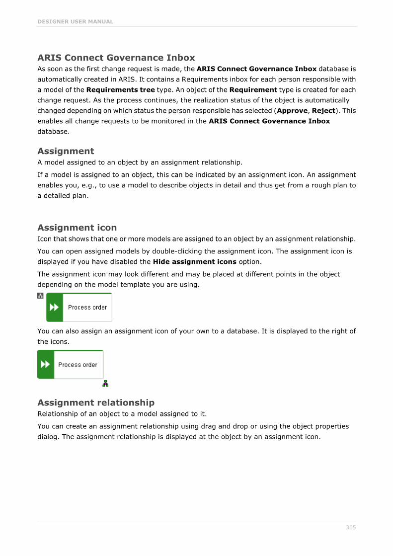
DESIGNER USER MANUAL
305
ARIS Connect Governance Inbox As soon as the first change request is made, the ARIS Connect Governance Inbox database is automatically created in ARIS. It contains a Requirements inbox for each person responsible with a model of the Requirements tree type. An object of the Requirement type is created for each change request. As the process continues, the realization status of the object is automatically changed depending on which status the person responsible has selected (Approve, Reject). This enables all change requests to be monitored in the ARIS Connect Governance Inbox database.
Assignment A model assigned to an object by an assignment relationship.
If a model is assigned to an object, this can be indicated by an assignment icon. An assignment enables you, e.g., to use a model to describe objects in detail and thus get from a rough plan to a detailed plan.
Assignment icon Icon that shows that one or more models are assigned to an object by an assignment relationship.
You can open assigned models by double-clicking the assignment icon. The assignment icon is displayed if you have disabled the Hide assignment icons option.
The assignment icon may look different and may be placed at different points in the object depending on the model template you are using.
You can also assign an assignment icon of your own to a database. It is displayed to the right of the icons.
Assignment relationship Relationship of an object to a model assigned to it.
You can create an assignment relationship using drag and drop or using the object properties dialog. The assignment relationship is displayed at the object by an assignment icon.

DESIGNER USER MANUAL
306
B
BPMN Business Process Model and Notation (BPMN) is a graphical notation used to describe business processes.
C
Change list (versioning) Includes selected content of a database. This may comprise individual models, multiple models without interdependencies, related models, group content, or the entire database contents. They will be versioned together and saved under one change list number. Change lists are sorted in ascending order.
A description of the change list characterizes the versioned contents. The change list description records who versioned which database content, when, and why. Opening a change list displays the database content you selected for versioning. This can be a model, or the entire database content.
Change list number (versioning) Number and description of a version of the database content. Change list numbers can be used to select particular versions for viewing. You have only read access for the content.
Change lists are sorted in ascending order. (Versioning state)
CRON expression String consisting of six to seven fields that is separated by a space and represents a time.
Normally, a CRON expression is used to define routine jobs that are executed automatically at certain times by the system.
Fields
Seconds, mandatory field, valid value: 0-59, valid characters: *, /, , -.
Minutes, mandatory field, valid value: 0-59, valid characters: *, /, , -.
Hours, mandatory field, valid value: 0-59, valid characters: *, /, , -.
Day in month, mandatory field, valid value: 0-59, valid characters: *, /, , -.
Month, mandatory field, valid value: 0-12 or JAN-DEC, valid characters: *, /, , -.
Day of the week, mandatory field, valid value: 0-7 or SUN-SAT, valid characters: *, /, , -, ?, L, C, #.
Year, not a mandatory field, valid value: 1970-2010, valid characters: *, /, , -.

DESIGNER USER MANUAL
307
Current version (versioning) Corresponds to the last versioned database content. This version includes the entire versioned content of a database. You have only read access for the content.
In principle, this is the last change list created for a database (versioning state).
D
Definition copy Copy of the object definition, i.e. of the entire object, rather than just the occurrence as is the case with the occurrence copy.
The definition copy creates a new object. The occurrence, which is created when creating the definition copy, refers to the new object.
You can create copies of objects. When copying an object, you can decide whether you wish to create a new object (a definition copy) or a new object symbol for an existing object (an occurrence copy).
It makes sense to create a definition copy for an existing object if a new object is to have properties similar to those of the source object.
For example, you have modeled the object Plant 1 and specified its properties. You now wish to create the object Plant 2, which has properties similar to Plant 1. In this case, it is advisable to create a definition copy of Plant 1. Object Plant 2 is thus given all the properties of object Plant 1, but exists independently of it. You now simply need to change the properties that differ from those of object Plant 1, for example, by changing the name to Plant 2.
This involves significantly less work for you than creating the object from scratch and having to enter all the properties again.
Some attributes are not copied when the definition copy is created. For example, it does not make sense to copy the identifier of an object because the identifier represents a unique ID of an object.
E
Escalation manager The escalation manager is the user who is notified when a human task is not completed by any executor by the due date.
F
Fully-qualified host name (FQHN) The fully-qualified host name (FQHN) is the host name that is specified as the IP address of a computer or as a fully-qualyfied domain name (FQDN) in the following form: my.department.example.com.

DESIGNER USER MANUAL
308
Function privilege Controls tasks that users can perform.
You can use function privileges to provide users with specific functionality and thus control their authorizations across a database in ARIS Architect. Function privileges are assigned on the properties pages of users or user groups. In ARIS Administration, administrators manage users, user groups, cross-database and cross-product privileges and licenses for all ARIS products.
G
Graphic objects Graphic elements without implicit semantic meaning. They can be used, for example, to indicate model areas, to specially highlight objects that are thematically linked, or to prepare models so that they are suitable for presentation.
Graphic elements include circles, squares, and polygons.
Grid Placement markings in the model window in the form of dots that you can show for modeling support (page 213).
These mark the minimum spacing between one model item and another. If you move an item, it is moved by increments of one gridline accordingly.
Grouping Grouped model items (page 261).
They can be moved, enlarged or reduced, and deleted as if they were one item.
GUID Globally Unique Identifier (GUID).
The GUID is a string that renders items unique anywhere in the world.
DESIGNER USER MANUAL
309
I
Impersonation Impersonation enables a user to perform actions on behalf of a different user account, e.g., backup and restore tenants. This requires the creation of a user in the user management for the infrastructure tenant, e.g., master. This user must be assigned all licenses and privileges that are needed for the action.
Infrastructure tenant Specifies the tenant with special privileges for managing other tenants, components, and the configuration in ARIS Administration.
By default, the master tenant is the infrastructure tenant. The system users system and superuser have administrative privileges, i.e., they can access ARIS Administration and Tenant Management.
Users with the relevant privileges can specify other infrastructure tenants in ARIS Administration.
J
JAAS Java Authentication and Authorization Service (JAAS).
A Java interface that enables you to provide services for authentication and access privileges in Java programs. JAAS supports user-based authentication.

DESIGNER USER MANUAL
310
K
Connection Visible relationship between objects, which is created during modeling. It is thus a graphical representation of a relationship.
A connection is usually represented by lines in the model window. If a direction is relevant, the line is added an arrow. One example is the connection of the is predecessor of type between functions in models of the EPC (event-driven process chain) type.
Connection, implicit Invisible connection.
Implicit connections are created if the Create implicit connections for overlapping objects option is enabled and objects are placed within objects. In the displayed dialog, you can decide whether to hide any connections and, if so, which connections to hide for these objects. The difference between implicit connections and implicit relationships is that an implicit connection can be represented by a line in the model window. This line is displayed again, for example, if you drag an object from another object down into the free area of the model window.
Example of implicit connections:
Place a function on another function in a model of the EPC type.

DESIGNER USER MANUAL
311
In a model of the PCD type, place a function in the Function column and an organizational unit in the Organizational unit column. An implicit connection of the 'carries out' type is automatically created from the organizational unit to the function.
This needs to be differentiated from implicit relationships (page 313).
L
Lane model Model represented using columns/rows or a table.
Lanes are columns and/or rows. They include only specific object types and they structure the modeled information. An implicit relationship is often created between objects in a row.
A model of the EPC (table display) type is a lane model.
M
Method filter Filter restricting the total number of ARIS Method items and thus offering only those items for modeling that are actually required.
By applying a specific method filter, only the model types included in this method filter will be offered for selection when creating new models. When modeling, all object, connection, and attribute types are available for the model type that are contained in the method filter. Thus, the content offered is exactly the content you need for performing your tasks. Method filters are an effective means of supporting uniform modeling and make it possible to provide users with only the information and methods relevant to them.
Mini toolbar Toolbar of objects (page 220) that are used for placing and drawing connections.
It is shown if you select an object in the model.
Model template Basic settings that change the appearance and attribute placements of models all at once when being assigned. This enables you to apply settings defined once to all relevant models. Templates can be assigned additively. This means that all changes from templates assigned one after the

DESIGNER USER MANUAL
312
other are valid. If, for example, you assign a template that removes the fill color of objects, and then assign a template that places the name attribute above the objects, both changes take effect.
O
Occurrence Graphical representation of objects, connections, and free-form texts.
It is used to represent items in a model.
With an occurrence copy several occurrences of an object can be created. These can differ within a model and/or in different models, i.e., object symbol, size, color, and attribute placements can be set individually and thus be different.
If the placed text attributes of an occurrence are changed, the changes are applied to all occurrences at which the text attribute has also been placed. For example , if the name an object is changed, the change is displayed for all occurrences.
Occurrence copy Copy of the occurrence, i.e., only the graphical representation of an object, rather than the entire object as with the definition copy.
All of the occurrence copies of an object represent the underlying object definition.
You can create copies of objects. When copying an object, you can decide whether you wish to create a new object (a definition copy) or a new object symbol for an existing object (an occurrence copy).
It is helpful to create a copy of the object symbol for an existing object - i.e., only a copy of the occurrence of an object - if exactly the same object is used at various positions in the model or in different models.
For example, if, in the model you are creating, Plant 1 supplies goods at various points of the model, it is advisable to use occurrence copies at these points. These refer to the same object, and any changes to this object apply to all occurrence copies.
If you want to rename Plant 1 to Plant A, for example, you only need to do this for ONE of the occurrences: All other occurrences are changed to Plant A at the same time.
OLE object OLE objects are objects from various external applications, which can be used in ARIS. When you start the objects from within ARIS, they are opened in the external application.
For them to open, specific requirements must be met. For example, the security policy of the Web browser must allow opening, and saved objects must be stored in a local drive.

DESIGNER USER MANUAL
313
OTP One-Time Pad (OTP).
This one-time pad is a symmetric encryption method for transferring secret messages. This encryption method is characterized by the fact that it uses a key of the same length as the message itself. The OTP is information-theoretically secure and has proven to be impossible to crack – provided that it is used properly.
P
ARIS Process Board ARIS Process Board is used for editing tasks that are provided by Process Governance during process execution. In addition, ARIS Process Board provides an overview of a user's active tasks.
R
Relationship Connection that can exist between model elements and among models.
Relationships include connections, implicit connections, implicit relationships, assignment, and variant relationships. Therefore, the term relationship is a superordinate term for all links that can exist between objects and models.
Relationship, implicit Assignment relationship, i.e., a relationship between objects for which no visible connection is drawn.
You create this relationship by assigning a model to an object.
This needs to be differentiated from implicit connections.
Root element Model or object that is used as the top element in a hierarchy in the portal. This element is displayed when you open the hierarchy in the portal.
S
SAML Security Assertion Markup Language (SAML).
XML framework for exchanging authentication and authorization information. SAML provides functions to describe and transfer security-related information.

DESIGNER USER MANUAL
314
Satellite A satellite is an object that can be inserted in a model or diagram but is not a structurally relevant object (page 314) in the model or diagram.
For example, an object of the Organizational unit type is a satellite in an event-driven process chain (EPC). In a model of the Organizational chart type, on the other hand, an object of the Organizational unit type is a structurally relevant object.
Single log-out (SLO) The advantage of using SLO is that users need log out only once from the network.
Single sign-on (SSO) The advantage of using SSO is that users need to remember only one password when logging in to the network. After entering the password at their workspace, they have access to all computers, services and programs for which they have the required privileges, without having to enter the password again.
SSL Secure Socket Layer (SSL).
Security software for encrypting data that is exchanged between programs.
Structurally relevant objects Basic model objects.
These are objects that indicate the distinctive feature of a model. For a model of the Organizational chart type, the objects Organizational unit, Role, and Person are structurally relevant objects, for example. Using these items, you can build the typical hierarchy of an organizational chart.
The Event and Function objects are typical for the EPC model type and are thus structurally relevant to a business process. You can use these to establish the typical control flow. The Organizational unit, Role, and Person objects can also be inserted into an EPC. However, these objects do not constitute the distinctive feature of a business process. As structurally irrelevant objects, they act as satellites, and add more detailed information to the process model. For example, you can insert organizational units and link them to functions to illustrate who carries out those functions.
An object that can be inserted in a model or diagram but is not a structurally relevant object is known as a satellite (page 314).

DESIGNER USER MANUAL
315
superuser The user superuser is created automatically. By default, this user is assigned the User management, License management, and Configuration administrator function privileges. This user can also activate this function privilege for other users. The superuser user does not use up a license. The superuser user manages the system administration, but cannot use ARIS products due to license restrictions. The default password is superuser. You should change the default password to prevent unauthorized access. You can change all user data except for the user name.
system The system user system assumes the administrator role of the system administrator and has all function and access privileges in all databases. Authorized persons can use this emergency user to log in to any database, even if you are using an external system, such as LDAP, for authentication.
The name system cannot be changed. The System user check box for this user (Function privileges properties page) cannot be disabled either. You should immediately change the password manager to prevent unauthorized access.
To avoid problems, you should create additional system users. If you forgot the passwords of all your system users, the full range of functions and access to the data in this database are no longer available to you.
System users System users are users who have all function and access privileges in a database and who have the required privileges in ARIS Administration. System users can be created by the system administrator (user system) or by another system user.
The system user system is created automatically. The name system cannot be changed. A system user should immediately change the password manager in ARIS Administration to prevent unauthorized access. The function and access privileges of system users cannot be changed at database level. To withdraw privileges from a system user, another system user must disable the System user check box on the user's Function privileges properties page. As a result, the user's privileges can be changed. After this, the user has no access privileges.
The system user system assumes the administrator role of the system administrator and has all function and access privileges in all databases. Authorized persons can use this emergency user to log in to any database, even if you are using an external system, such as LDAP, for authentication.
The name system cannot be changed. The System user check box for this user (Function privileges properties page) cannot be disabled either. You should immediately change the password manager to prevent unauthorized access.
To avoid problems, you should create additional system users. If you forgot the passwords of all your system users, the full range of functions and access to the data in this database are no longer available to you.
What is the user 'arisservice'?

DESIGNER USER MANUAL
316
System database This database manages the content of the Configuration and Evaluations folders, which is displayed on the Administration tab. This includes filters, templates, and font formats, but also ARIS Method and all common files, report scripts, scheduled reports, semantic checks and macros.
The system database is created automatically while the first user is logging in to ARIS. The content is available for all databases of this tenant. The ARIS Service Administrator commands backupsystemdb, restoresystemdb, and updatesystemdb can be used to save and restore this data centrally.
After performing an update setup, please update the system configuration of the tenant (filters, templates, and scripts) based on the supplied system database (ARIS_DVD/Content/SystemDB/*.adb). Any content you have created will be retained.
Syntax
updatesystemdb <archive>
Restores the central system database that contains data such as filters, model templates, and scripts from a system database backup file (ADB) <archive>. It is also possible for you to update the system database using the updatesystemdb command
After performing an update setup, please update the system configuration of the tenant (filters, templates, and scripts) based on the supplied system database (ARIS_DVD/Content/SystemDB/*.adb). Any content you have created will be retained.
Syntax
updatesystemdb <archive>
Syntax
restoresystemdb <archive>
Saves the central system database that contains data such as filters, model templates, and scripts in an ADB file in a directory <archivedir>.
Syntax
backupsystemdb <archivedir> [<alternatename>]
T
Tenant Provides a user with a particular functionality and specific data depending on their license. One ARIS Administration exists for each tenant. All ARIS clients use tenants to access database servers and thus work with a common data basis. For each tenant, there is a configuration on the Administration tab that defines ARIS Method and the modeling conventions. These are used by all databases on that tenant.
All tenants are managed using the Infrastructure tenant.

DESIGNER USER MANUAL
317
TLS Transport Layer Security (TLS).
TLS is known under the name of its predecessor Secure Sockets Layer (SSL) and is an encryption protocol for the secure transfer of data on the Internet.
U
UML (Unified Modeling Language) UML is a graphical modeling language for specifying, constructing, and documenting software, parts of software, and other systems. This "unified" modeling language specifies the notations of the modeling terms and their relationships. It also defines the graphical notation, the static structures, and the dynamic processes.
URI String that is used to uniquely identify an abstract or physical resource.
URIs are used to describe resources (such as Web sites, other files, calls for Web services) on the Internet.
URIs can be incorporated as a string (encoded with a character set) into digital documents, particularly those in HTML format, or written by hand. A link from one Web site to another is called a hyperlink.
URL Uniform Resource Locator, a particular type of URI (Uniform Resource Identifier).
URLs identify a resource via the network protocol used (e.g., http or ftp) and the location of the resource (e.g., of a service) in a network.
The term URL is often used synonymously with URI because URLs were the first and are still the most frequently used type of URI.
User name Name of a user (e.g., system) for access to a database. The user name does not necessarily have to correspond to a person's real name.
Access to a database is possible if a user logs in to it with the combination of user name and password that has previously been stored for the database. This is the case when the system administrator or a user with the User management function privilege creates the new user.
DESIGNER USER MANUAL
318
V
Version A model that remains fixed and can no longer be changed in a change list.
The versioning state of the last version created is the current version.
Version number Number assigned to a model during versioning.
The number relates to the model whose versions are numbered in ascending order.
Versioning state Image of database content recorded at a certain point in time.
A versioning state can include models of different versions with different or identical version numbers that represent a specific state. While Workspace represents a state that is editable but has not yet been versioned, the versions are included in the Current version state and in the revisions associated with the Change list numbers.
W
Workspace (versioning) Indicates the database content that has not yet been versioned. It can be edited. (Versioning state)

DESIGNER USER MANUAL
319
5 Support information
5.1 Support
ONLINE
A valid support contract allows you to access the solution database.
Click https://empower.softwareag.com/ (https://empower.softwareag.com/).
If you have any questions on specific installations that you cannot perform yourself, please contact your local Software AG sales organization.
BY TELEPHONE
If you have a valid support contract, you can contact Global Support ARIS at:
+800 ARISHELP
The plus sign stands for the prefix required in a given country to dial an international connection.
Example for dialing within Germany with a direct extension line: 00 800 2747 4357
5.2 Disclaimer
ARIS products are intended and developed for use by persons. Automated processes, such as the generation of content and the import of objects/artifacts via interfaces, can lead to an outsized amount of data, and their execution may exceed processing capacities and physical limits. For example, processing capacities are exceeded if models and diagrams transcend the size of the modeling area or an extremely high number of processing operations is started simultaneously. Physical limits may be exceeded if the memory available is not sufficient for the execution of operations or the storage of data.
Proper operation of ARIS products requires the availability of a reliable and fast network connection. Networks with insufficient response time will reduce system performance and may cause timeouts.
If ARIS products are used in a virtual environment, sufficient resources must be available there in order to avoid the risk of overbooking.
The system was tested using scenarios that included 100,000 groups (folders), 100,000 users, and 1,000,000 modeling artifacts. It supports a modeling area of 25 square meters.
If projects or repositories are larger than the maximum size allowed, a powerful functionality is available to break them down into smaller, more manageable parts.

DESIGNER USER MANUAL
I
6 Index
A Alfabet
Alfabet • 286 ARIS and Alfabet • 286 Configuration • 286 Create object • 263 Map objects • 262 Unmap object • 263
ARIS Aware Dashboard Customer experience • 166 Dashboard Customer journey map • 173 Dashboard EA IT systems • 184 Dashboard EA objectives • 187 Dashboard EA organizational units • 180 Dashboard Piwik - Publications • 176 Dashboard Piwik - Technical KPIs • 178 Dashboard Responsibilities • 170
ARIS document storage Customer experience • 166
Assignment Create new • 204
Attribute As a symbol • 259 Documentation • 249 Edit • 221 Format placed attributes • 221 Hide always • 208 Hide, if not specified • 208 Move placed attribute • 258 Name of placed attributes • 257 Place anywhere • 256 Place fixed • 255 Place from Attributes bar • 257 Placed • 279 Remove placement • 259 Select placed attributes • 257
Attributes bar Set up • 208 Show and hide • 206
B BPMN
Add lane • 225 Assign global reference • 228 Change loop type • 224 Change sequence flow • 226 Change symbol • 218 Collapse subprocess • 227 Delete pool or lane • 226 Edit subprocess • 227 Expand subprocess • 227 Lane into a pool or lane • 225 Move lane • 225
Transform communication • 226
C Change symbol • 218 Collaboration
Add documents to posts • 194 Create filter • 195 Create groups • 197 Create user profile • 189 Filter feeds • 196 Follow feeds • 190 Getting started • 189 Group types • 202 Invite user(s) • 198 Open Collaboration • 189 Target group for posts • 200 Use hashtags • 196 Use tags • 195
Comment Collaboration bar • 264
Connection Implicit (term) • 310 Line style • 254 Line weight • 254 Term • 310
Contribution Change values • 104 Changeable items • 110 Create item in list • 106 Delete item from list • 108 Delete item from table • 107 Edit mode • 109 Editable attributes • 111 Editing options • 112 Item in table • 105 Prerequisites • 109 Saved items • 115
Coordinator Edit requests • 199 Pass on privilege • 199
Copy Definition copy • 214 Occurrence copy • 214
Create group • 205
D Dashboards
Customer experience • 166 Customer journey map • 173 EA IT systems • 184 EA objectives • 187 EA organizational units • 180 Piwik - Publications • 176 Piwik - Technical KPIs • 178 Responsibilities • 170

DESIGNER USER MANUAL
II
Database selection • 48 Display bar • 264 Document
Add documents • 86 Assign • 247 Link document to model or object • 74 Lock • 90 Move • 89 Rename • 81 Unlock • 91 Upload version • 88
F Favorite
Favorites area • 103 Filter settings as favorite • 97 Use favorite settings • 97 Use favorite settings (Favorites area) • 98
Feed Assign • 210 Definition • 200 Follow in ARIS Connect (group) • 198 Follow in ARIS Connect (user) • 191 Reset • 211
Find bar • 264
G Glossary
Change glossary page • 52 Choose item • 50 Filter glossary • 51 Remove filter • 51
Grid Change width • 210 Set width • 214 Show • 213
L Language • 213 Lock
Models • 301 Objects • 302 Unlock models • 302 Unlock objects • 303
M Method filter
Display current • 53 Mini toolbar
Configure • 209 Modeling • 220 Show and hide • 209 Structure • 279
Model Adjust appearance • 223 Align items • 261 Assignment • 204 Attribute as a symbol • 259 Change item appearance • 255 Color elements • 252 Color items • 251 Create connections • 222 Create new • 203 Create new as an assignment • 204 Delete items • 223 Display items without color • 253 Edit attributes • 221 Element with gradient • 252 Find objects • 244 Format painter • 251 Group items • 261 Name of placed attributes • 257 Occurrence in Explorer • 262 Open • 212 Place attribute (anywhere) • 256 Place attribute (fixed position) • 255 Place graphic objects • 218 Place items one behind the other • 260 Place object symbols • 214 Place text • 223 Remove attribute placement • 259 Save • 224 Select placed attributes • 257 Show grid • 213 Ungroup • 261
Model Editor Customize • 206 Definition copy • 214 Display bar • 264 Find objects • 244 Grid • 213 Mini toolbar • 279 Occurrence copy • 214 Set up Attributes bar • 208 Set up Symbols bar • 207 Structure • 264
Model item Align • 261 Change appearance • 255 Color • 252 Color borders and lines • 253 Delete • 223 Display without color • 253 Format painter • 251 Gradient • 252 Group • 261 Line style • 254 Line weight • 254 One behind the other • 260 Reset border and line color • 254

DESIGNER USER MANUAL
III
Ungroup • 261
N Notification • 194
O Object
In an object • 245 Object in objects • 280 Occurrence in Explorer • 262 On an object • 246
Object symbol Change • 218 Color • 251, 252 Create assignment • 260 Display without color • 253 Find objects • 244 Gradient • 252 Line style • 254 Line weight • 254 One behind the other • 260 Place • 214 Reset border and line color • 254 Reset color • 253
Occurrence/Presentation Display order • 133 Occurrence copy • 214
P Place • 218 Portal
ARIS Online Guide • 119 Move placed attribute • 258 Navigation • 49 Open assignment • 63 Placed link attribute • 63 Portal profiles • 9 Print model graphic • 53 Run transaction • 116 SAP documentation • 117 Switch form Steps to Diagram • 52
Post Comment, share, flag, etc. • 193 Publish • 192
Profile Create/edit for Collaboration • 190 Edit for ARIS Connect • 3 Edit your profile • 3
R RACI
Available base diagrams • 122 Base diagram • 120 Display matrix • 121
Relationship Implicit (term) • 313 Term • 313
Report Available • 141 Export graphic • 142 Generate • 54 Generate job description • 144 Output formats • 154 Output functions • 146 Output model information • 149 Output object information • 151 Output various model information • 150 Print model graphic • 53 Process manual • 151 RA(S)CI • 152 Reports bar • 264 Run • 68
S Search
Open Search area • 94 Quick search • 101 Search area • 102 Search context • 96 Search results • 103 Start • 93
Symbols bar Set up • 207
T Table based modeling
Add attribute column • 233 Add object column • 233 Arrange columns • 234 BPMN • 240 Create object • 229 Edit attribute • 234 Full-screren mode • 229 Modeling table • 228 Modeling using the keyboard • 236 Remove column • 235 Satellites • 232 Split paths • 231 Use existing objects • 230
Tabs BPMN tab bar • 278 Format tab bar • 277 Model tab bar • 276 Start tab bar • 275
Template Assign • 210 Reset • 211

DESIGNER USER MANUAL
IV
U UML
Display • 137 Prerequisites • 137
V Version
Models • 299 Open version • 300 Show versions • 300
View Navigation • 49 SAP documentation • 117