Embed Size (px)
Citation preview
ARION 1 – Payload User Guide
Ref: ARION1_PUG Version: 1.2 Created Checked Approved
Project/department: ARION1/Mission 08 Jun 2018 08 Jun 2018 08 Jun 2018
Doc Name: ARION 1 – Payload User Guide MFN FGL RTB
Public Information 0/42 © Payload Aerospace S.L.
ARION 1 – Payload User Guide
Version 1.2, 08 June 2018
© Payload Aerospace S.L.
ARION 1 – Payload User Guide
Ref: ARION1_PUG Version: 1.2 Created Checked Approved
Project/department: ARION1/Mission 08 Jun 2018 08 Jun 2018 08 Jun 2018
Doc Name: ARION 1 – Payload User Guide MFN FGL RTB
Public Information 2/42 © Payload Aerospace S.L.
I. VERSION CONTROL
Version Date Author Chapters Changes
1.0 22 March 2018 M. Nürmberger All Document Creation
1.1 31 May 2018 M. Nürmberger II 1.3, 1.4 2.1.1 2.2 4.3 4.5 4.4 & 4.5 2.1.2.4 & 5.2.2 7 All Footer
Acronym List completed and updated Description of Standard and Non-Standard Services included INTA logo used to mark launch site position Misleading Information (Figure 2-7) removed Information about required payload documentation and reviews updated Late access operation further explained Illustrations added Flexible composition of Payload Bay explained Chapter 7: Safety added Spelling and grammar mistakes corrected Small clarifications added Changed to “Public Information”
1.2 08 June 2018 M. Nürmberger 2.1.2 3.4 4.5 5.1.2 5.2.2 6.3.2.1
Small updates, Information about GMV included Figure 3-6 changed Countdown & flight timeline updated Orientation of coordinate frame updated Nosecone dimensions updated Random vibration spectrum source updated
NOTE: This document is still in draft status. The provided information still is subject to change and does not
commit PLD Space. Mechanical and electrical interfaces might evolve during the finalization of the design. Flight
performance and environment data currently is the result of simulations and will be replaced with real data as
soon as it is available.
ARION 1 – Payload User Guide
Version 1.2
Public Information 3/42 © Payload Aerospace S.L.
II. ACRONYMS
CD Countdown C&DH Command & Data Handling FTS Flight Termination System HQ Headquarters ICD Interface Control Document LOX Liquid Oxygen MECO Main Engine Cut Off PDP Payload Data Package P/L Payload PLB Payload Bay PLC Payload Computer PLD PLD Space – Payload Aerospace, S.L. PQ Payload Questionnaire PUG Payload User Guide RCS Reaction Control System TEPREL Tecnología Española de Propulsión Espacial para Lanzadores TVC Thrust Vector Control
ARION 1 – Payload User Guide
Version 1.2
Public Information 4/42 © Payload Aerospace S.L.
III. PREFACE
The ARION 1 Payload User Guide is a document published by PLD Space to provide general information about
the ARION 1 suborbital launch vehicle. This document provides information about the ARION 1 launcher, its
performance capabilities, payload interfaces and all the associated services that PLD Space provides to its
customers.
Comments or suggestions on all aspects of this manual are appreciated. With inquiries concerning clarification
or interpretation of this manual or for further information please contact:
PLD Space Mission Department Calle Nicolás Copérnico 7 Parque Empresarial de Elche 03203 Elche (Alicante) SPAIN Telephone: +34 965 063 139 Email: [email protected]
NOTE: This User Guide is a working document, and as such is revised and updated periodically. When working
with this document, please ensure you have the latest and complete version which is available on the PLD Space
website.
NOTE: Throughout the document, a dot “.” is used as decimal mark.
ARION 1 – Payload User Guide
Version 1.2
Public Information 5/42 © Payload Aerospace S.L.
IV. INDEX OF CONTENT
1. Introduction ................................................................................................................................................. 8
1.1. PLD Space ..............................................................................................................................................8
1.2. Why ARION 1 ........................................................................................................................................8
1.3. Standard Services ..................................................................................................................................8
1.4. Non-Standard Services ..........................................................................................................................8
2. Vehicle Overview ......................................................................................................................................... 9
2.1. Vehicle Description ...............................................................................................................................9
2.1.1. Baseline Configuration ..................................................................................................................9
2.1.2. Subsystems ................................................................................................................................ 10
2.1.2.1. Propulsion System .............................................................................................................. 10
2.1.2.2. Recovery System ................................................................................................................ 10
2.1.2.3. Avionics System .................................................................................................................. 10
2.1.2.4. Payload Bay ........................................................................................................................ 11
2.2. Performance ...................................................................................................................................... 12
3. Ground Facilities ........................................................................................................................................ 14
3.1. Headquarters ..................................................................................................................................... 14
3.2. Mobile Launch Ramp ......................................................................................................................... 16
3.3. Launch Site ......................................................................................................................................... 16
3.4. Propulsion Test Facilities .................................................................................................................... 18
4. Mission Timeline ........................................................................................................................................ 19
4.1. Overview ............................................................................................................................................ 19
4.2. Flight Ticket Procurement .................................................................................................................. 19
4.3. Payload Development ........................................................................................................................ 19
4.4. Payload Integration and Testing ........................................................................................................ 21
4.5. Launch Campaign & Flight ................................................................................................................. 22
5. Payload Interfaces ...................................................................................................................................... 26
5.1. Definitions .......................................................................................................................................... 26
5.1.1. Dimensions and Tolerances ....................................................................................................... 26
5.1.2. Coordinate Frame ...................................................................................................................... 26
5.2. Mechanical Interface ......................................................................................................................... 26
5.2.1. Payload Mass ............................................................................................................................. 26
5.2.2. Payload Envelope ....................................................................................................................... 27
ARION 1 – Payload User Guide
Version 1.2
Public Information 6/42 © Payload Aerospace S.L.
5.2.3. Payload Mounting ...................................................................................................................... 28
5.2.4. Payload Compartment Access.................................................................................................... 28
5.2.4.1. Bulkhead Fitting Clearance................................................................................................. 28
5.2.4.2. Hatch Dimensions .............................................................................................................. 29
5.3. Electrical Interface ............................................................................................................................. 30
5.3.1. Power Supply ............................................................................................................................. 30
5.3.1.1. Power Supply Characteristics ............................................................................................. 30
5.3.1.2. Power Connector ............................................................................................................... 30
5.3.2. Command & Data Handling........................................................................................................ 30
5.3.2.1. C&DH System Overview ..................................................................................................... 30
5.3.2.2. Payload Control .................................................................................................................. 30
5.3.2.3. Payload Telemetry and Data Storage ................................................................................. 31
5.3.2.4. C&DH Connector ................................................................................................................ 31
6. Payload Evnironmental Conditions ............................................................................................................ 32
6.1. Atmospheric Conditions ..................................................................................................................... 32
6.1.1. Payload Bay ................................................................................................................................ 32
6.1.2. Launch Site ................................................................................................................................. 32
6.2. Thermal Environment ........................................................................................................................ 33
6.2.1. Pre-Flight .................................................................................................................................... 33
6.2.1.1. Payload Integration and Testing......................................................................................... 33
6.2.1.2. Payload Transport .............................................................................................................. 33
6.2.1.3. Launch Preparations .......................................................................................................... 33
6.2.2. Flight .......................................................................................................................................... 34
6.2.3. Post-Flight .................................................................................................................................. 34
6.3. Mechanical Loads............................................................................................................................... 35
6.3.1. Pre-Flight .................................................................................................................................... 35
6.3.1.1. Random Vibrations ............................................................................................................. 35
6.3.1.2. Static Loads ........................................................................................................................ 36
6.3.2. Flight .......................................................................................................................................... 36
6.3.2.1. Random Vibrations ............................................................................................................. 36
6.3.2.1. Static Loads ........................................................................................................................ 37
6.3.2.2. Acoustic Loads ................................................................................................................... 37
6.3.2.3. Shock Loads ........................................................................................................................ 38
ARION 1 – Payload User Guide
Version 1.2
Public Information 7/42 © Payload Aerospace S.L.
7. Safety ......................................................................................................................................................... 39
7.1. Safety Requirements .......................................................................................................................... 39
7.2. Waivers .............................................................................................................................................. 39
8. Document References................................................................................................................................ 40
8.1. List of Figures ..................................................................................................................................... 40
8.2. List of Tables ...................................................................................................................................... 41
9. Bibliography ............................................................................................................................................... 42
ARION 1 – Payload User Guide
Version 1.2
Public Information 8/42 © Payload Aerospace S.L.
1. INTRODUCTION
1.1. PLD SPACE
PLD Space is a European space company which goal is to provide commercial and scientific access to space. We
are developing a family of reusable microlaunchers to offer suborbital and orbital launch services for small
satellites and payloads.
The first member of our launcher family is the ARION 1 sounding rocket, designed for suborbital flights. It
provides our customers with valuable microgravity time for scientific research or technology development.
1.2. WHY ARION 1
With ARION 1, PLD Space is fully committed to revolutionize the commercial access to space for scientific and
technological purposes. We are focused to provide the best flight experience to our customers. Best experience
is not only flying on a reliable system and meeting mission goals but also to meet an easy integration of your
experiment.
By simplifying the way of integrating your experiment on the launcher, PLD Space reduces overall mission time
but also simplifies the interface between the experiment and the launcher.
1.3. STANDARD SERVICES
As part of any flight, PLD Space offers the following services, which are also described in further detail in the
following chapters:
Execution of a launch campaign including one suborbital flight.
Support during the payload development and documentation.
Payload integration at PLD Space facilities.
Functional and Interference testing.
Several flight simulation tests to ensure payload combability with flight procedures and to train the
customers ground control team.
Facilitate the launch range safety process.
One flight bulkhead and one flight set of electrical connectors.
Payload interfaces for power supply, C&DH and mounting.
Payload compartment conditioned with gaseous nitrogen or any other inert gas on request.
Payload transport from PLD Space headquarters to the launch site.
Late Access to the payload while the rocket is on the launch pad.
Payload recovery.
Distribution of a post flight performance report and vehicle housekeeping data.
1.4. NON-STANDARD SERVICES
Services which are not part of the standard flight ticket can be realized on a case-by-case basis in consultation
with PLD Space.
ARION 1 – Payload User Guide
Version 1.2
Public Information 9/42 © Payload Aerospace S.L.
2. VEHICLE OVERVIEW
2.1. VEHICLE DESCRIPTION
2.1.1. Baseline Configuration
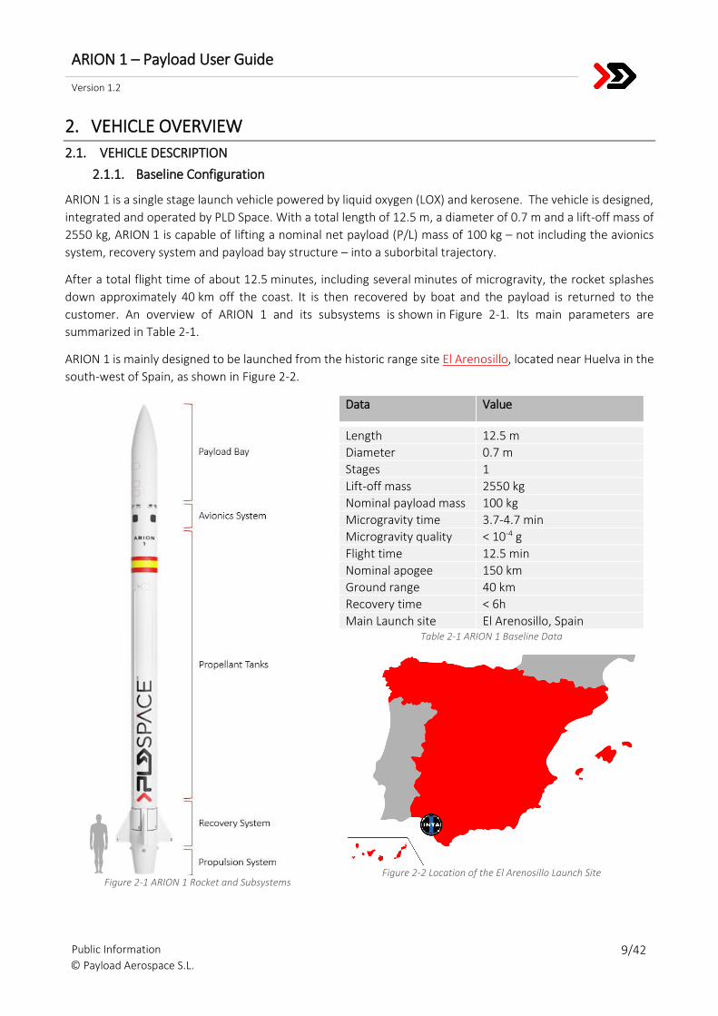
ARION 1 is a single stage launch vehicle powered by liquid oxygen (LOX) and kerosene. The vehicle is designed,
integrated and operated by PLD Space. With a total length of 12.5 m, a diameter of 0.7 m and a lift-off mass of
2550 kg, ARION 1 is capable of lifting a nominal net payload (P/L) mass of 100 kg – not including the avionics
system, recovery system and payload bay structure – into a suborbital trajectory.
After a total flight time of about 12.5 minutes, including several minutes of microgravity, the rocket splashes
down approximately 40 km off the coast. It is then recovered by boat and the payload is returned to the
customer. An overview of ARION 1 and its subsystems is shown in Figure 2-1. Its main parameters are
summarized in Table 2-1.
ARION 1 is mainly designed to be launched from the historic range site El Arenosillo, located near Huelva in the
south-west of Spain, as shown in Figure 2-2.
Figure 2-1 ARION 1 Rocket and Subsystems
Data Value
Length 12.5 m
Diameter 0.7 m
Stages 1
Lift-off mass 2550 kg
Nominal payload mass 100 kg
Microgravity time 3.7-4.7 min
Microgravity quality < 10-4 g
Flight time 12.5 min
Nominal apogee 150 km
Ground range 40 km
Recovery time < 6h
Main Launch site El Arenosillo, Spain Table 2-1 ARION 1 Baseline Data
Figure 2-2 Location of the El Arenosillo Launch Site
ARION 1 – Payload User Guide
Version 1.2
Public Information 10/42 © Payload Aerospace S.L.
2.1.2. Subsystems
2.1.2.1. Propulsion System
ARION 1 is propelled by a single regeneratively cooled TEPREL-1B engine powered by liquid oxygen (LOX) and
kerosene. This single stage propulsion system has been designed and optimized by PLD Space to provide the
best mission performance scenario in every single flight.
The propellants are driven to the engine by using a pressure-fed cycle with Helium. The TEPREL-1B liquid rocket
engine produces a total thrust at sea level of 30 kN for a total duration of 122 seconds until depletion of the
propellant tanks. Furthermore, the propulsion system is equipped with actuators to tilt the engine for an active
Thrust Vector Control (TVC) during the propelled ascent of ARION 1.
2.1.2.2. Recovery System
The recovery system on board of ARION 1 can safely return the whole launch vehicle to ground, enabling the
payloads to be returned to the customers and the complete rocket to be used again. After reentry, two
parachutes are deployed consecutively. At an altitude of approximately 5 km, a drogue parachute decelerates
the rocket, until the main parachute can be opened safely. At an altitude of approximately 3 km, the main
parachute is deployed and further slows-down the descent of ARION 1. Finally, the vehicle splashes down with
a terminal velocity of 10 m/s. With the last known GPS position and a beacon system, it is then possible to locate
the vehicle floating on the sea surface and recover it with a boat.
2.1.2.3. Avionics System
The avionics system, developed by the Spanish technology group GMV,
controls all vehicle functions during the flight. It is also the only system directly
connected to the payloads flying on ARION 1, as it is responsible for their power
supply, telemetry and Command & Data Handling (C&DH). The general
functions of the avionics system are:
Guidance, Navigation & Control: The avionics system controls the trajectory and the attitude of ARION 1
during its flight by commanding the actuators of the main engines TVC and by an additional Reaction
Control System (RCS). The RCS is composed of cold-gas thrusters using nitrogen.
Telemetry System: Establishes the communication between the vehicle and the ground station to
transfer vehicle and payload telemetry.
Power Storage and Distribution: Equipped with batteries for power storage and a power conditioning
and distribution unit, the avionics system is responsible for supporting all remaining rocket systems and
the payloads with power.
Payload Management: A dedicated Payload Computer (PLC) handles all communication between the
avionics system and the individual payloads. It forwards the payload telemetry to the telemetry system,
provides additional data storage capacities and sends control signals to the payloads.
Sensor Conditioning and Acquisition: The ARION 1 rocket is equipped with various different sensors that
are used for rocket control loops, but also deliver valuable housekeeping data to analyze the rocket’s
performance after the flight.
Figure 2-3 GMV Logo

ARION 1 – Payload User Guide
Version 1.2
Public Information 11/42 © Payload Aerospace S.L.
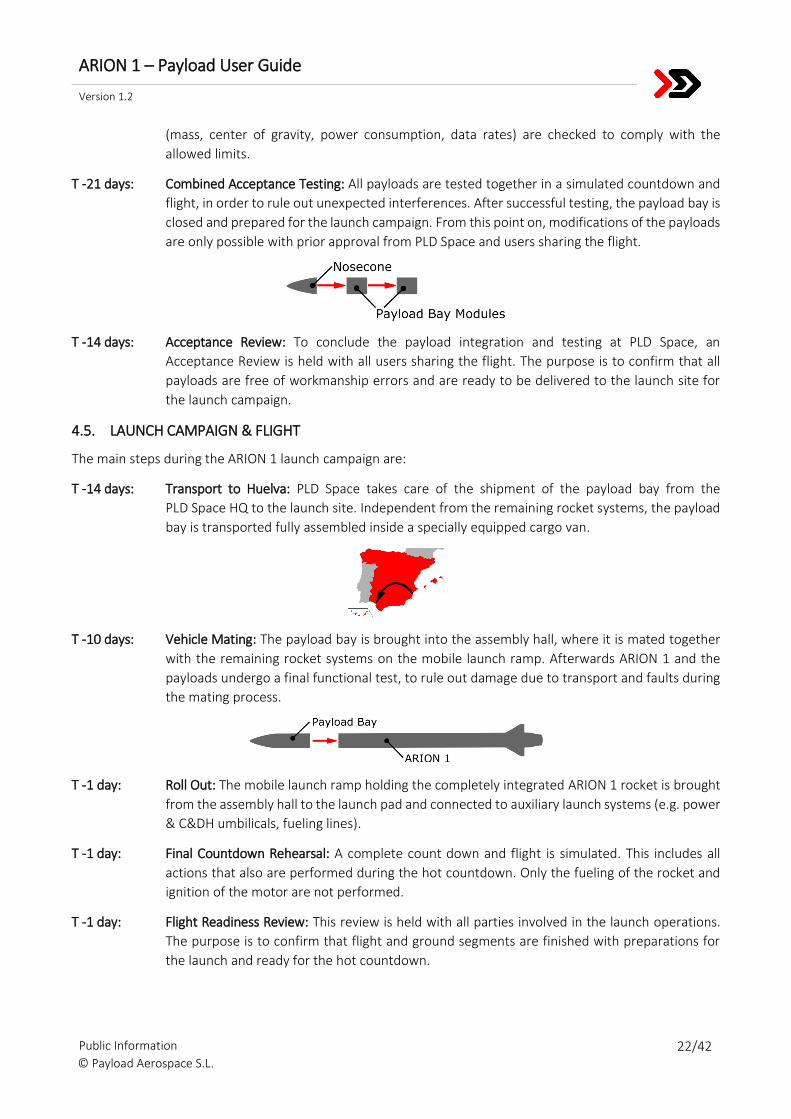
2.1.2.4. Payload Bay
The ARION 1 payload bay (PLB) is placed on top of the avionics bay and extends into
the tip of the rocket. It consists of the nosecone and several modules that are stacked
below it. The payload bay is capable to house up to four different payloads inside
separated payload compartments (shown in Figure 2-4). The bulkheads between
them are equipped with an isogrid pattern of screw holes for payload mounting and
provide connections to the avionics bay for power supply, telemetry and C&DH.
Hatches allow easier access during the integration process and enable late access to
the payload during the count-down. Each compartment is sealed airtight individually
and stays pressurized during the flight. A more detailed description of the payload
interfaces can be found in Section 5.
Payload compartments exist in three different forms:
Single Compartment: Suitable for simpler payloads, offering basic mass
budget, power supply, data storage and telemetry data-rate.
Double Compartment: Meant for more demanding payloads, offering twice the volume, mass limit,
power supply, data storage capacity and telemetry data-rate.
Nosecone: Can be utilized as either sized compartment, depending on the payload demands and
composition of each mission.
The distribution of single and double compartments can be adapted individually for each flight, depending on
the mission composition and the volume demands of the customer(s). Also, the combination of two or more
compartments to form a triple or quadruple compartment is possible.
Figure 2-4 Cut view of two single compartments inside a
payload bay module

ARION 1 – Payload User Guide
Version 1.2
Public Information 12/42 © Payload Aerospace S.L.
2.2. PERFORMANCE
The flight performance of each ARION 1 flight is strongly depending on the total payload mass. Figure 2-5 shows
simulation results estimating how the payload mass influences the total achievable microgravity (< 10-3 g) time.
The achievable flight altitude also depends on the total payload mass. Simulation results are shown in Figure
2-6.
Figure 2-5 Achievable Microgravity Time vs. Total Payload Mass
Figure 2-6 Achievable Altitude vs. Total Payload Mass
200
225
250
275
300
50 75 100 125 150
Ach
ieva
ble
Mic
rogr
avit
y Ti
me,
s
Total Payload Mass, kg
130
140
150
160
170
180
50 75 100 125 150
Ach
ieva
ble
Ap
oge
e, k
m
Total Payload Mass, kg
ARION 1 – Payload User Guide
Version 1.2
Public Information 13/42 © Payload Aerospace S.L.
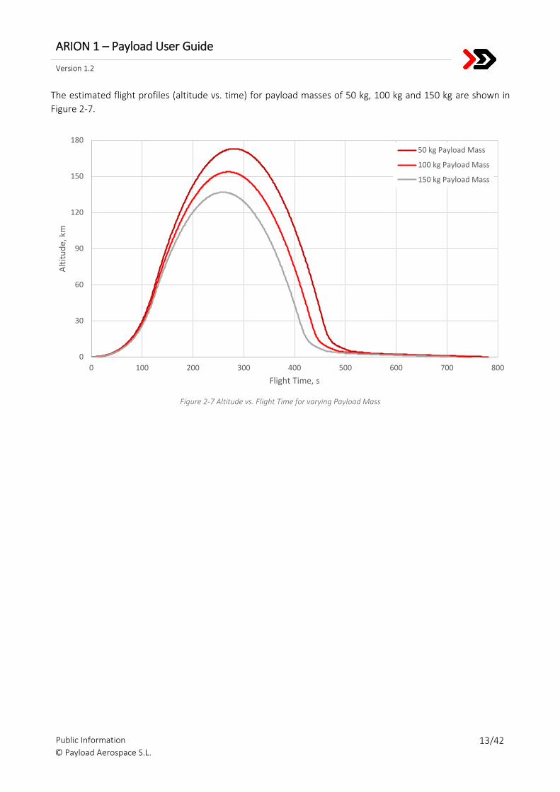
The estimated flight profiles (altitude vs. time) for payload masses of 50 kg, 100 kg and 150 kg are shown in
Figure 2-7.
Figure 2-7 Altitude vs. Flight Time for varying Payload Mass
0
30
60
90
120
150
180
0 100 200 300 400 500 600 700 800
Alt
itu
de,
km
Flight Time, s
50 kg Payload Mass
100 kg Payload Mass
150 kg Payload Mass
ARION 1 – Payload User Guide
Version 1.2
Public Information 14/42 © Payload Aerospace S.L.
3. GROUND FACILITIES
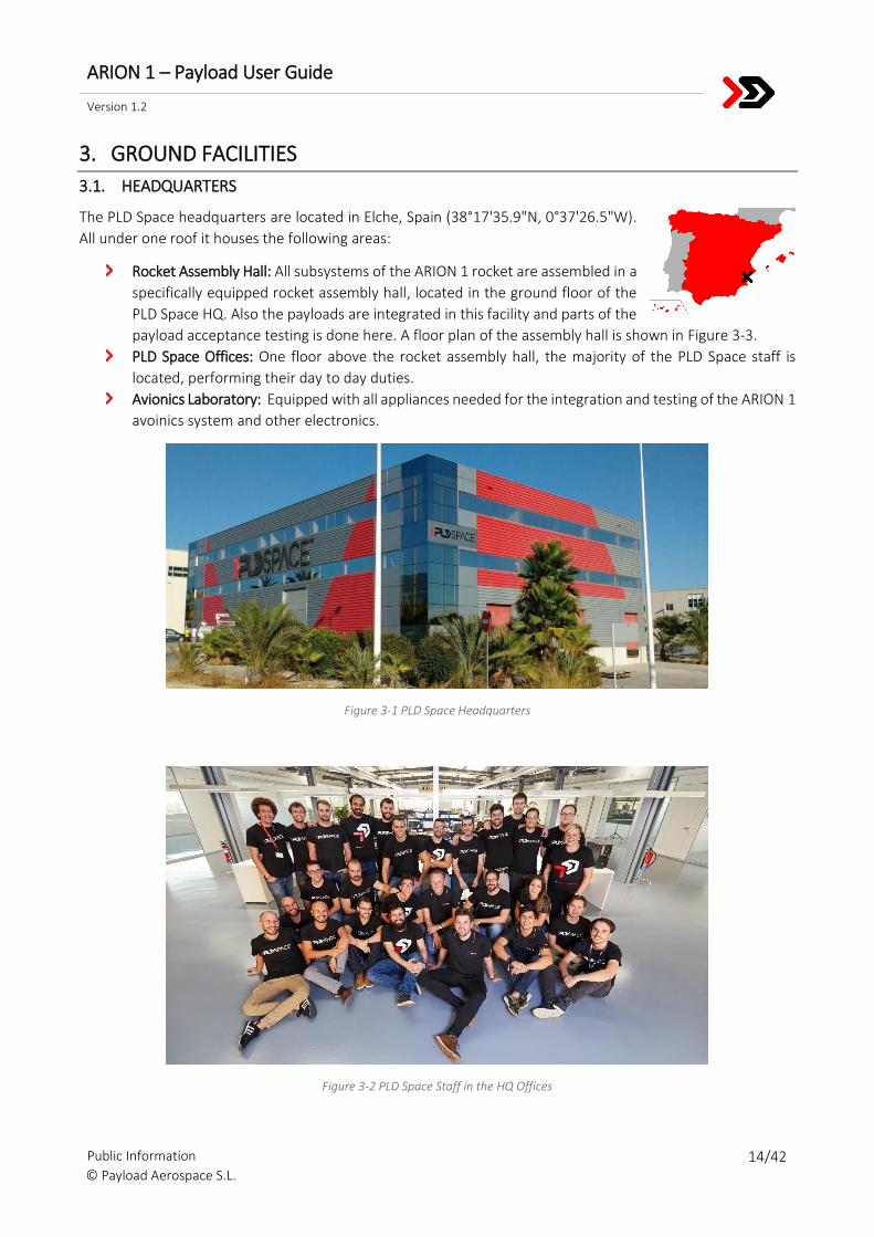
3.1. HEADQUARTERS
The PLD Space headquarters are located in Elche, Spain (38°17'35.9"N, 0°37'26.5"W).
All under one roof it houses the following areas:
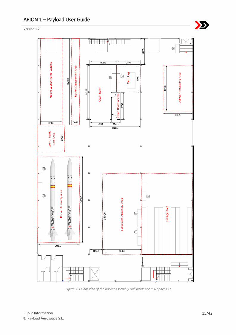
Rocket Assembly Hall: All subsystems of the ARION 1 rocket are assembled in a
specifically equipped rocket assembly hall, located in the ground floor of the
PLD Space HQ. Also the payloads are integrated in this facility and parts of the
payload acceptance testing is done here. A floor plan of the assembly hall is shown in Figure 3-3.
PLD Space Offices: One floor above the rocket assembly hall, the majority of the PLD Space staff is
located, performing their day to day duties.
Avionics Laboratory: Equipped with all appliances needed for the integration and testing of the ARION 1
avoinics system and other electronics.
Figure 3-1 PLD Space Headquarters
Figure 3-2 PLD Space Staff in the HQ Offices
ARION 1 – Payload User Guide
Version 1.2
Public Information 15/42 © Payload Aerospace S.L.
Figure 3-3 Floor Plan of the Rocket Assembly Hall inside the PLD Space HQ
ARION 1 – Payload User Guide
Version 1.2
Public Information 16/42 © Payload Aerospace S.L.
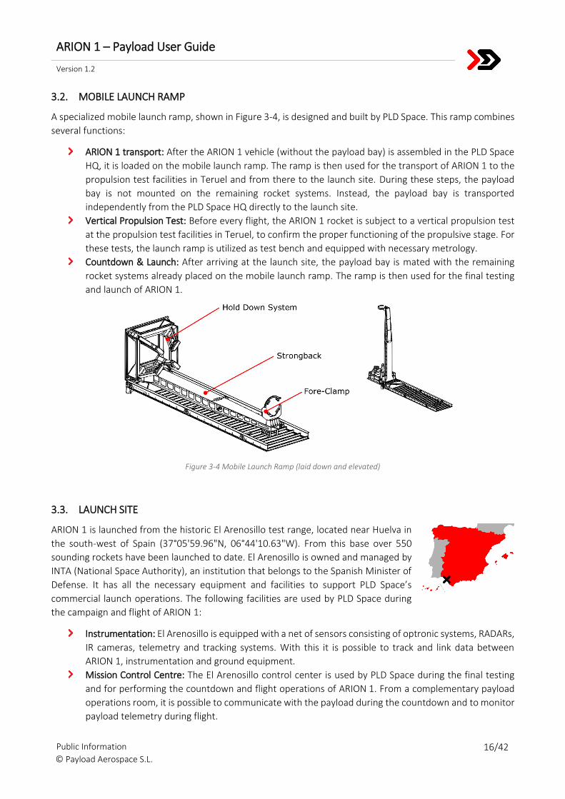
3.2. MOBILE LAUNCH RAMP
A specialized mobile launch ramp, shown in Figure 3-4, is designed and built by PLD Space. This ramp combines
several functions:
ARION 1 transport: After the ARION 1 vehicle (without the payload bay) is assembled in the PLD Space
HQ, it is loaded on the mobile launch ramp. The ramp is then used for the transport of ARION 1 to the
propulsion test facilities in Teruel and from there to the launch site. During these steps, the payload
bay is not mounted on the remaining rocket systems. Instead, the payload bay is transported
independently from the PLD Space HQ directly to the launch site.
Vertical Propulsion Test: Before every flight, the ARION 1 rocket is subject to a vertical propulsion test
at the propulsion test facilities in Teruel, to confirm the proper functioning of the propulsive stage. For
these tests, the launch ramp is utilized as test bench and equipped with necessary metrology.
Countdown & Launch: After arriving at the launch site, the payload bay is mated with the remaining
rocket systems already placed on the mobile launch ramp. The ramp is then used for the final testing
and launch of ARION 1.
Figure 3-4 Mobile Launch Ramp (laid down and elevated)
3.3. LAUNCH SITE
ARION 1 is launched from the historic El Arenosillo test range, located near Huelva in
the south-west of Spain (37°05'59.96"N, 06°44'10.63"W). From this base over 550
sounding rockets have been launched to date. El Arenosillo is owned and managed by
INTA (National Space Authority), an institution that belongs to the Spanish Minister of
Defense. It has all the necessary equipment and facilities to support PLD Space’s
commercial launch operations. The following facilities are used by PLD Space during
the campaign and flight of ARION 1:
Instrumentation: El Arenosillo is equipped with a net of sensors consisting of optronic systems, RADARs,
IR cameras, telemetry and tracking systems. With this it is possible to track and link data between
ARION 1, instrumentation and ground equipment.
Mission Control Centre: The El Arenosillo control center is used by PLD Space during the final testing
and for performing the countdown and flight operations of ARION 1. From a complementary payload
operations room, it is possible to communicate with the payload during the countdown and to monitor
payload telemetry during flight.
ARION 1 – Payload User Guide
Version 1.2
Public Information 17/42 © Payload Aerospace S.L.
Meteorological Service: The base has its own aeronautical meteo-information center, that is available
24 hours. Short and long weather forecasts can be performed, including high altitude conditions and
jet streams.
Auxiliary Services: Further facilities to support the launch operations are available. This includes e.g.
offices, administration, access controls, medical services, fire equipment, generators and water supply.
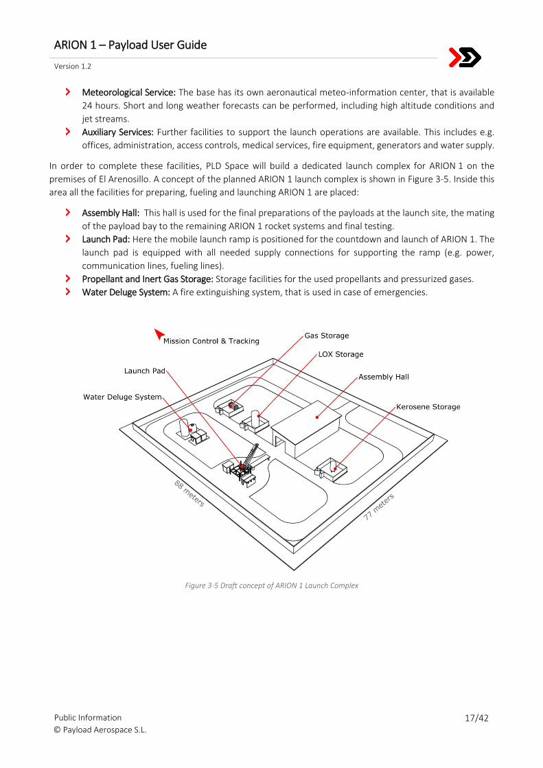
In order to complete these facilities, PLD Space will build a dedicated launch complex for ARION 1 on the
premises of El Arenosillo. A concept of the planned ARION 1 launch complex is shown in Figure 3-5. Inside this
area all the facilities for preparing, fueling and launching ARION 1 are placed:
Assembly Hall: This hall is used for the final preparations of the payloads at the launch site, the mating
of the payload bay to the remaining ARION 1 rocket systems and final testing.
Launch Pad: Here the mobile launch ramp is positioned for the countdown and launch of ARION 1. The
launch pad is equipped with all needed supply connections for supporting the ramp (e.g. power,
communication lines, fueling lines).
Propellant and Inert Gas Storage: Storage facilities for the used propellants and pressurized gases.
Water Deluge System: A fire extinguishing system, that is used in case of emergencies.
Figure 3-5 Draft concept of ARION 1 Launch Complex
ARION 1 – Payload User Guide
Version 1.2
Public Information 18/42 © Payload Aerospace S.L.
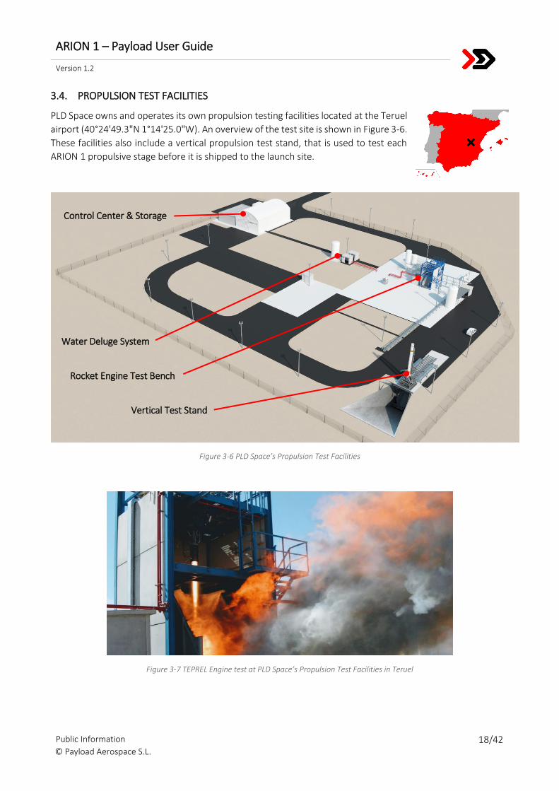
3.4. PROPULSION TEST FACILITIES
PLD Space owns and operates its own propulsion testing facilities located at the Teruel
airport (40°24'49.3"N 1°14'25.0"W). An overview of the test site is shown in Figure 3-6.
These facilities also include a vertical propulsion test stand, that is used to test each
ARION 1 propulsive stage before it is shipped to the launch site.
Figure 3-6 PLD Space’s Propulsion Test Facilities
Figure 3-7 TEPREL Engine test at PLD Space’s Propulsion Test Facilities in Teruel
Vertical Test Stand
Water Deluge System
Rocket Engine Test Bench
Control Center & Storage
ARION 1 – Payload User Guide
Version 1.2
Public Information 19/42 © Payload Aerospace S.L.
4. MISSION TIMELINE
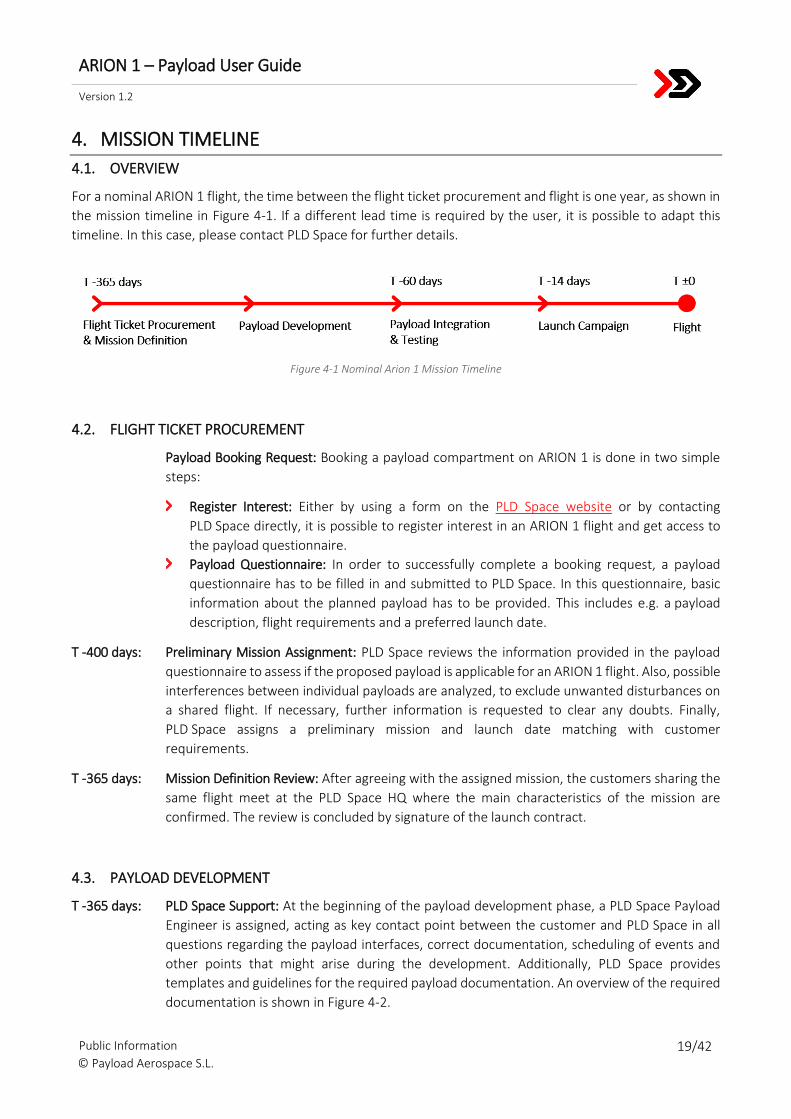
4.1. OVERVIEW
For a nominal ARION 1 flight, the time between the flight ticket procurement and flight is one year, as shown in
the mission timeline in Figure 4-1. If a different lead time is required by the user, it is possible to adapt this
timeline. In this case, please contact PLD Space for further details.
Figure 4-1 Nominal Arion 1 Mission Timeline
4.2. FLIGHT TICKET PROCUREMENT
Payload Booking Request: Booking a payload compartment on ARION 1 is done in two simple
steps:
Register Interest: Either by using a form on the PLD Space website or by contacting
PLD Space directly, it is possible to register interest in an ARION 1 flight and get access to
the payload questionnaire.
Payload Questionnaire: In order to successfully complete a booking request, a payload
questionnaire has to be filled in and submitted to PLD Space. In this questionnaire, basic
information about the planned payload has to be provided. This includes e.g. a payload
description, flight requirements and a preferred launch date.
T -400 days: Preliminary Mission Assignment: PLD Space reviews the information provided in the payload
questionnaire to assess if the proposed payload is applicable for an ARION 1 flight. Also, possible
interferences between individual payloads are analyzed, to exclude unwanted disturbances on
a shared flight. If necessary, further information is requested to clear any doubts. Finally,
PLD Space assigns a preliminary mission and launch date matching with customer
requirements.
T -365 days: Mission Definition Review: After agreeing with the assigned mission, the customers sharing the
same flight meet at the PLD Space HQ where the main characteristics of the mission are
confirmed. The review is concluded by signature of the launch contract.
4.3. PAYLOAD DEVELOPMENT
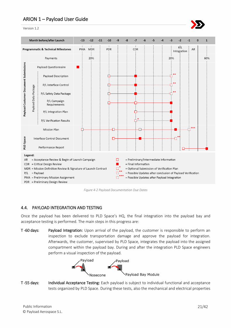
T -365 days: PLD Space Support: At the beginning of the payload development phase, a PLD Space Payload
Engineer is assigned, acting as key contact point between the customer and PLD Space in all
questions regarding the payload interfaces, correct documentation, scheduling of events and
other points that might arise during the development. Additionally, PLD Space provides
templates and guidelines for the required payload documentation. An overview of the required
documentation is shown in Figure 4-2.
ARION 1 – Payload User Guide
Version 1.2
Public Information 20/42 © Payload Aerospace S.L.
T- 300 days: Preliminary Design Review: The first issue of the Payload Data Package (PDP) has to be handed
in by the customer. PLD Space will perform a review of the documentation and follow up on
potential arising issues. The PDP is a single document, containing the following information
about the payload:
Payload Description: Includes information about the payload’s purpose and functions, as
well as an explanation of the overall payload design and the performed operations during
the countdown and flight.
Payload Interface Control: Documents the design of the payload interfaces, to make sure
the payload is compliant with the interfaces described in the Payload User Guide (PUG).
Payload Safety Data Package: Lists all hazards and safety risks resulting from the payload
during ground operations and flight.
Payload Campaign Requirements: Lists needed facilities, necessary procedures and
materials, allowed boundary conditions and other requirements for the launch campaign
and flight.
Payload Integration Plan: Describes the necessary integration procedures and correct
handling of the payload. Explains which facilities need to be used and which materials are
needed for the proper integration and acceptance testing of the payload at the PLD Space
headquarters.
Payload Verification Results: Documentation verifying that payload complies with test
requirements specified by PLD Space.
CAD Model: Used by PLD Space to do a virtual fit check and a preliminary determination of
mass properties for evaluating vehicle flight dynamics and performance.
With the provided information, PLD Space will issue a first version of the Interface Control
Document and update the Mission Plan, a document summarizing campaign and flight
requirements of all payloads as well as describing the overall campaign schedule and foreseen
flight performance. PLD Space will also start the launch range safety process.
T -215 days: Critical Design Review: A second iteration of the PDP is due. PLD Space will review the provided
documentation, follow up on arising issues, update the Mission Plan and Interface Control
Document and close the launch range safety process.
T -90 days: Final Payload Documentation: The customer is responsible to hand in the final version of the
PDP with final updates prior commencing the payload integration at the PLD Space
headquarters.
ARION 1 – Payload User Guide
Version 1.2
Public Information 21/42 © Payload Aerospace S.L.
Figure 4-2 Payload Documentation Due Dates
4.4. PAYLOAD INTEGRATION AND TESTING
Once the payload has been delivered to PLD Space’s HQ, the final integration into the payload bay and
acceptance testing is performed. The main steps in this progress are:
T -60 days: Payload Integration: Upon arrival of the payload, the customer is responsible to perform an
inspection to exclude transportation damage and approve the payload for integration.
Afterwards, the customer, supervised by PLD Space, integrates the payload into the assigned
compartment within the payload bay. During and after the integration PLD Space engineers
perform a visual inspection of the payload.
T -55 days: Individual Acceptance Testing: Each payload is subject to individual functional and acceptance
tests organized by PLD Space. During these tests, also the mechanical and electrical properties
ARION 1 – Payload User Guide
Version 1.2
Public Information 22/42 © Payload Aerospace S.L.
(mass, center of gravity, power consumption, data rates) are checked to comply with the
allowed limits.
T -21 days: Combined Acceptance Testing: All payloads are tested together in a simulated countdown and
flight, in order to rule out unexpected interferences. After successful testing, the payload bay is
closed and prepared for the launch campaign. From this point on, modifications of the payloads
are only possible with prior approval from PLD Space and users sharing the flight.
T -14 days: Acceptance Review: To conclude the payload integration and testing at PLD Space, an
Acceptance Review is held with all users sharing the flight. The purpose is to confirm that all
payloads are free of workmanship errors and are ready to be delivered to the launch site for
the launch campaign.
4.5. LAUNCH CAMPAIGN & FLIGHT
The main steps during the ARION 1 launch campaign are:
T -14 days: Transport to Huelva: PLD Space takes care of the shipment of the payload bay from the
PLD Space HQ to the launch site. Independent from the remaining rocket systems, the payload
bay is transported fully assembled inside a specially equipped cargo van.
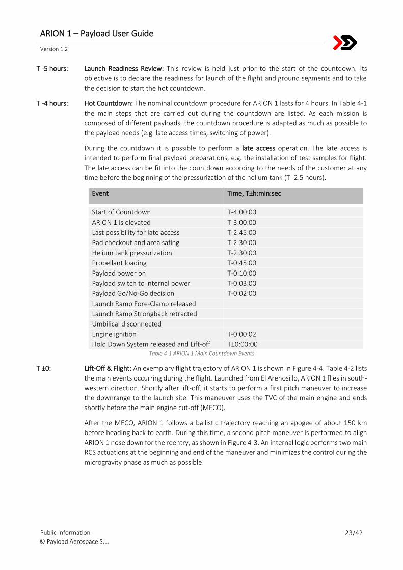
T -10 days: Vehicle Mating: The payload bay is brought into the assembly hall, where it is mated together
with the remaining rocket systems on the mobile launch ramp. Afterwards ARION 1 and the
payloads undergo a final functional test, to rule out damage due to transport and faults during
the mating process.
T -1 day: Roll Out: The mobile launch ramp holding the completely integrated ARION 1 rocket is brought
from the assembly hall to the launch pad and connected to auxiliary launch systems (e.g. power
& C&DH umbilicals, fueling lines).
T -1 day: Final Countdown Rehearsal: A complete count down and flight is simulated. This includes all
actions that also are performed during the hot countdown. Only the fueling of the rocket and
ignition of the motor are not performed.
T -1 day: Flight Readiness Review: This review is held with all parties involved in the launch operations.
The purpose is to confirm that flight and ground segments are finished with preparations for
the launch and ready for the hot countdown.
ARION 1 – Payload User Guide
Version 1.2
Public Information 23/42 © Payload Aerospace S.L.
T -5 hours: Launch Readiness Review: This review is held just prior to the start of the countdown. Its
objective is to declare the readiness for launch of the flight and ground segments and to take
the decision to start the hot countdown.
T -4 hours: Hot Countdown: The nominal countdown procedure for ARION 1 lasts for 4 hours. In Table 4-1
the main steps that are carried out during the countdown are listed. As each mission is
composed of different payloads, the countdown procedure is adapted as much as possible to
the payload needs (e.g. late access times, switching of power).
During the countdown it is possible to perform a late access operation. The late access is
intended to perform final payload preparations, e.g. the installation of test samples for flight.
The late access can be fit into the countdown according to the needs of the customer at any
time before the beginning of the pressurization of the helium tank (T -2.5 hours).
Event Time, T±h:min:sec
Start of Countdown T-4:00:00
ARION 1 is elevated T-3:00:00
Last possibility for late access T-2:45:00
Pad checkout and area safing T-2:30:00
Helium tank pressurization T-2:30:00
Propellant loading T-0:45:00
Payload power on T-0:10:00
Payload switch to internal power T-0:03:00
Payload Go/No-Go decision T-0:02:00
Launch Ramp Fore-Clamp released
Launch Ramp Strongback retracted
Umbilical disconnected
Engine ignition T-0:00:02
Hold Down System released and Lift-off T±0:00:00 Table 4-1 ARION 1 Main Countdown Events
T ±0: Lift-Off & Flight: An exemplary flight trajectory of ARION 1 is shown in Figure 4-4. Table 4-2 lists
the main events occurring during the flight. Launched from El Arenosillo, ARION 1 flies in south-
western direction. Shortly after lift-off, it starts to perform a first pitch maneuver to increase
the downrange to the launch site. This maneuver uses the TVC of the main engine and ends
shortly before the main engine cut-off (MECO).
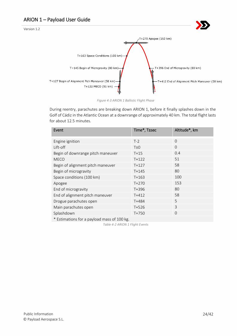
After the MECO, ARION 1 follows a ballistic trajectory reaching an apogee of about 150 km
before heading back to earth. During this time, a second pitch maneuver is performed to align
ARION 1 nose down for the reentry, as shown in Figure 4-3. An internal logic performs two main
RCS actuations at the beginning and end of the maneuver and minimizes the control during the
microgravity phase as much as possible.
ARION 1 – Payload User Guide
Version 1.2
Public Information 24/42 © Payload Aerospace S.L.
Figure 4-3 ARION 1 Ballistic Flight Phase
During reentry, parachutes are breaking down ARION 1, before it finally splashes down in the
Golf of Cádiz in the Atlantic Ocean at a downrange of approximately 40 km. The total flight lasts
for about 12.5 minutes.
Event Time*, T±sec Altitude*, km
Engine ignition T-2 0
Lift-off T±0 0
Begin of downrange pitch maneuver T+15 0.4
MECO T+122 51
Begin of alignment pitch maneuver T+127 58
Begin of microgravity T+145 80
Space conditions (100 km) T+163 100
Apogee T+270 153
End of microgravity T+396 80
End of alignment pitch maneuver T+412 58
Drogue parachutes open T+484 5
Main parachutes open T+526 3
Splashdown T+750 0
* Estimations for a payload mass of 100 kg. Table 4-2 ARION 1 Flight Events
ARION 1 – Payload User Guide
Version 1.2
Public Information 25/42 © Payload Aerospace S.L.
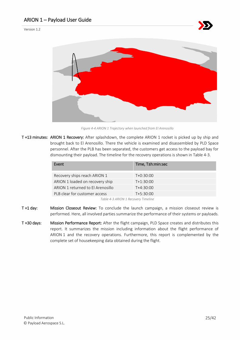
Figure 4-4 ARION 1 Trajectory when launched from El Arenosillo
T +13 minutes: ARION 1 Recovery: After splashdown, the complete ARION 1 rocket is picked up by ship and
brought back to El Arenosillo. There the vehicle is examined and disassembled by PLD Space
personnel. After the PLB has been separated, the customers get access to the payload bay for
dismounting their payload. The timeline for the recovery operations is shown in Table 4-3.
Event Time, T±h:min:sec
Recovery ships reach ARION 1 T+0:30:00
ARION 1 loaded on recovery ship T+1:30:00
ARION 1 returned to El Arenosillo T+4:30:00
PLB clear for customer access T+5:30:00 Table 4-3 ARION 1 Recovery Timeline
T +1 day: Mission Closeout Review: To conclude the launch campaign, a mission closeout review is
performed. Here, all involved parties summarize the performance of their systems or payloads.
T +30 days: Mission Performance Report: After the flight campaign, PLD Space creates and distributes this
report. It summarizes the mission including information about the flight performance of
ARION 1 and the recovery operations. Furthermore, this report is complemented by the
complete set of housekeeping data obtained during the flight.
ARION 1 – Payload User Guide
Version 1.2
Public Information 26/42 © Payload Aerospace S.L.
5. PAYLOAD INTERFACES
5.1. DEFINITIONS
5.1.1. Dimensions and Tolerances
Unless specified otherwise, all linear dimensions are in millimeters (mm) and all angular dimensions are in
degrees (°).
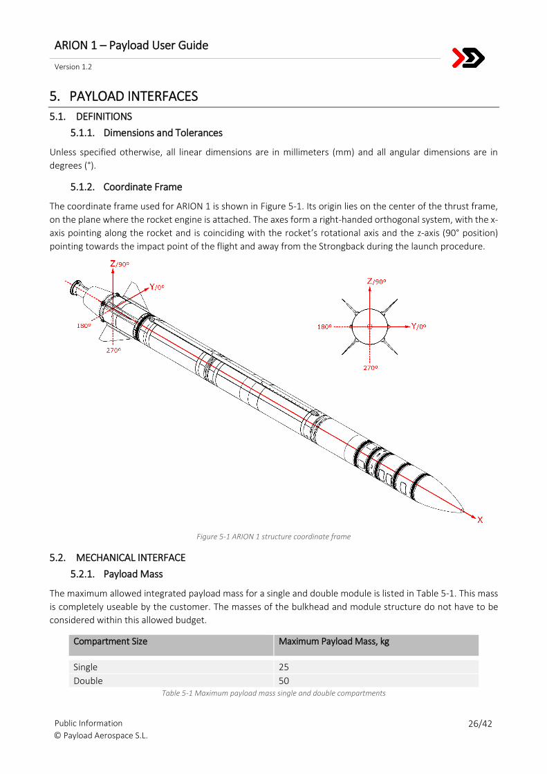
5.1.2. Coordinate Frame
The coordinate frame used for ARION 1 is shown in Figure 5-1. Its origin lies on the center of the thrust frame,
on the plane where the rocket engine is attached. The axes form a right-handed orthogonal system, with the x-
axis pointing along the rocket and is coinciding with the rocket’s rotational axis and the z-axis (90° position)
pointing towards the impact point of the flight and away from the Strongback during the launch procedure.
Figure 5-1 ARION 1 structure coordinate frame
5.2. MECHANICAL INTERFACE
5.2.1. Payload Mass
The maximum allowed integrated payload mass for a single and double module is listed in Table 5-1. This mass
is completely useable by the customer. The masses of the bulkhead and module structure do not have to be
considered within this allowed budget.
Compartment Size Maximum Payload Mass, kg
Single 25
Double 50 Table 5-1 Maximum payload mass single and double compartments
ARION 1 – Payload User Guide
Version 1.2
Public Information 27/42 © Payload Aerospace S.L.
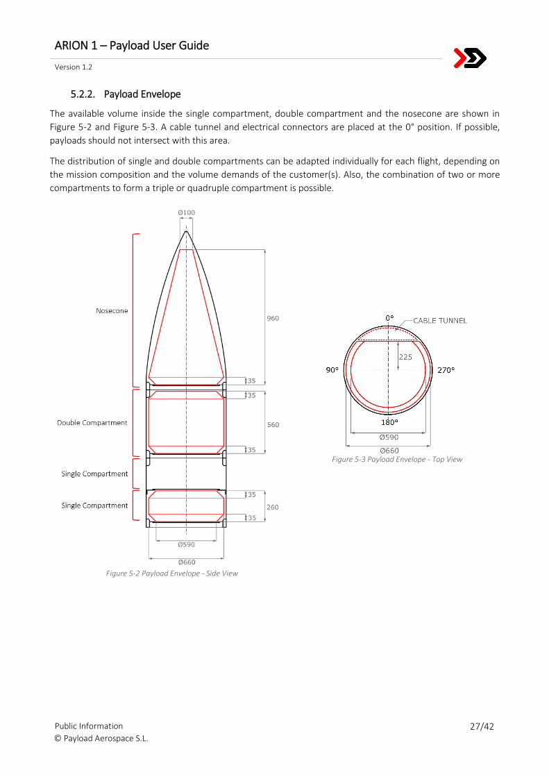
5.2.2. Payload Envelope
The available volume inside the single compartment, double compartment and the nosecone are shown in
Figure 5-2 and Figure 5-3. A cable tunnel and electrical connectors are placed at the 0° position. If possible,
payloads should not intersect with this area.
The distribution of single and double compartments can be adapted individually for each flight, depending on
the mission composition and the volume demands of the customer(s). Also, the combination of two or more
compartments to form a triple or quadruple compartment is possible.
Figure 5-2 Payload Envelope - Side View
Figure 5-3 Payload Envelope - Top View
ARION 1 – Payload User Guide
Version 1.2
Public Information 28/42 © Payload Aerospace S.L.
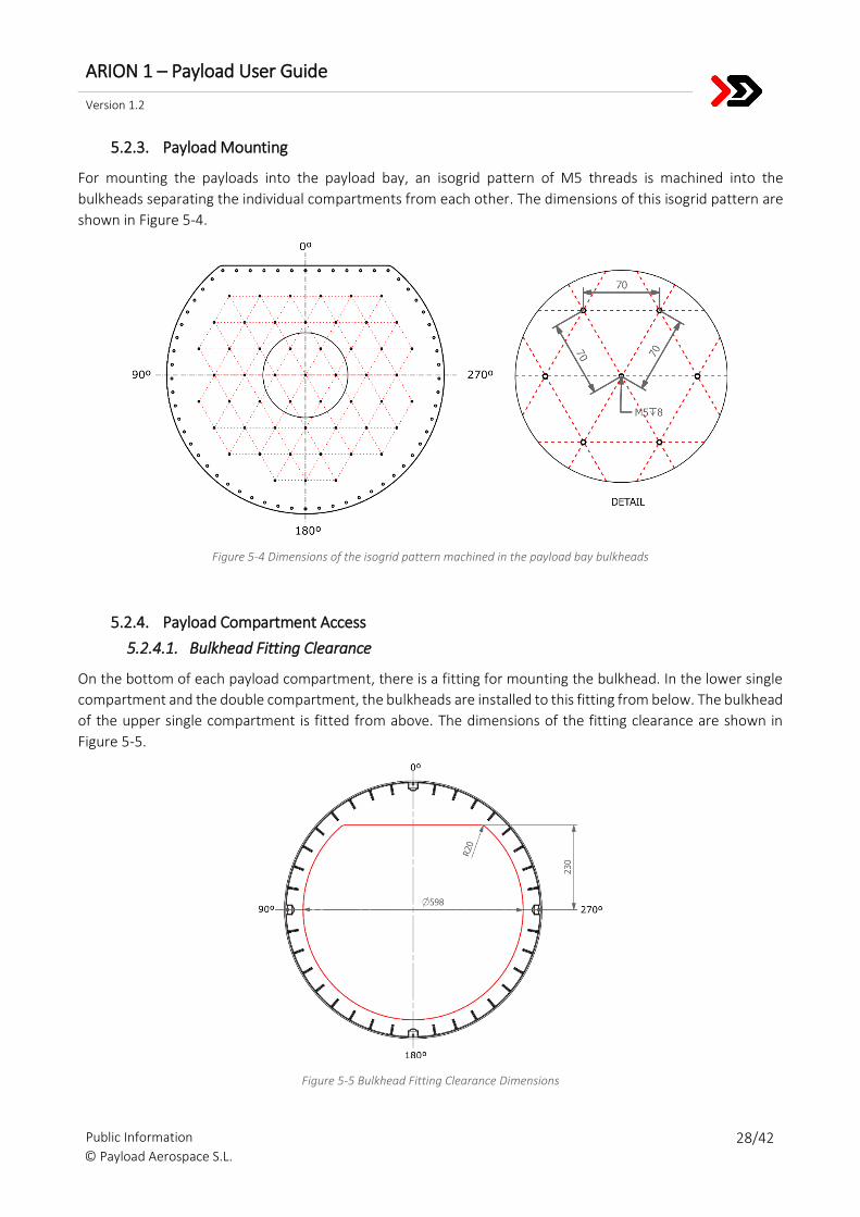
5.2.3. Payload Mounting
For mounting the payloads into the payload bay, an isogrid pattern of M5 threads is machined into the
bulkheads separating the individual compartments from each other. The dimensions of this isogrid pattern are
shown in Figure 5-4.
Figure 5-4 Dimensions of the isogrid pattern machined in the payload bay bulkheads
5.2.4. Payload Compartment Access
5.2.4.1. Bulkhead Fitting Clearance
On the bottom of each payload compartment, there is a fitting for mounting the bulkhead. In the lower single
compartment and the double compartment, the bulkheads are installed to this fitting from below. The bulkhead
of the upper single compartment is fitted from above. The dimensions of the fitting clearance are shown in
Figure 5-5.
Figure 5-5 Bulkhead Fitting Clearance Dimensions
ARION 1 – Payload User Guide
Version 1.2
Public Information 29/42 © Payload Aerospace S.L.
5.2.4.2. Hatch Dimensions
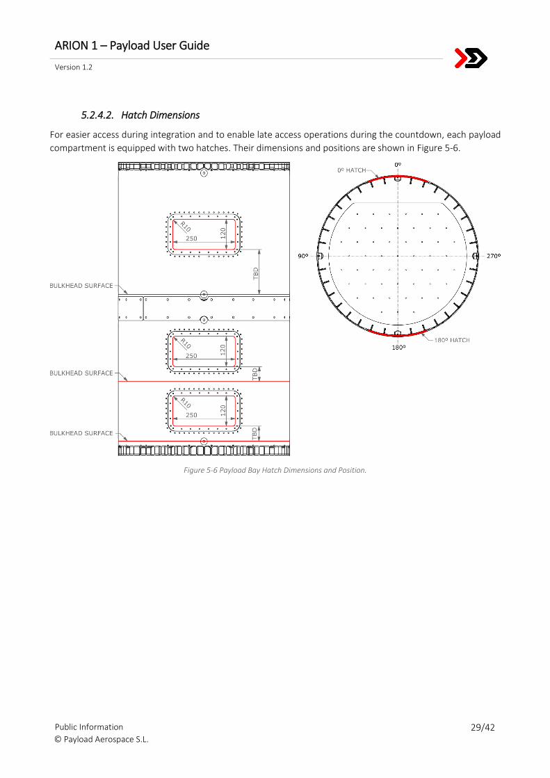
For easier access during integration and to enable late access operations during the countdown, each payload
compartment is equipped with two hatches. Their dimensions and positions are shown in Figure 5-6.
Figure 5-6 Payload Bay Hatch Dimensions and Position.
ARION 1 – Payload User Guide
Version 1.2
Public Information 30/42 © Payload Aerospace S.L.
5.3. ELECTRICAL INTERFACE
5.3.1. Power Supply
5.3.1.1. Power Supply Characteristics
The payload power supply provides a voltage of 28 V DC to the payloads. Per power connector a maximum
continuous current of 10 A is available, while ARION 1 is connected to external power.
While the payload is connected to external power, it is possible to manually switch the power supply (on/off),
if required.
On external power, it is also possible to charge additional payload batteries for the flight. If such batteries are
needed, consult with PLD Space. It is advised to make use of the available on-board power as good as possible,
before including additional batteries.
During the switch from external to internal battery power the payloads might experience a voltage step. Once
the payloads are supported by the on-board batteries, the nominal voltage stays at 28 V DC, but may vary
depending on the batteries temperature and charge condition.
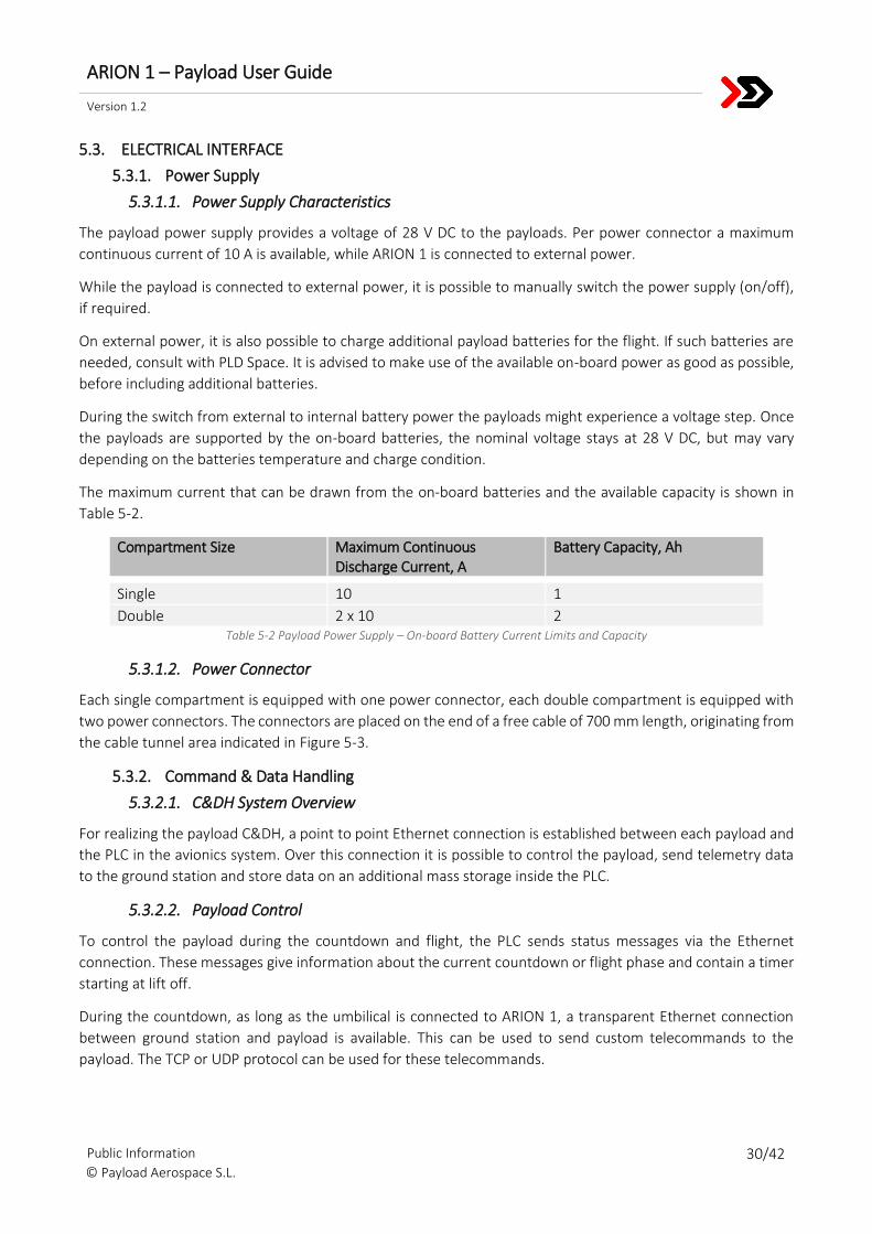
The maximum current that can be drawn from the on-board batteries and the available capacity is shown in
Table 5-2.
Compartment Size Maximum Continuous Discharge Current, A
Battery Capacity, Ah
Single 10 1
Double 2 x 10 2 Table 5-2 Payload Power Supply – On-board Battery Current Limits and Capacity
5.3.1.2. Power Connector
Each single compartment is equipped with one power connector, each double compartment is equipped with
two power connectors. The connectors are placed on the end of a free cable of 700 mm length, originating from
the cable tunnel area indicated in Figure 5-3.
5.3.2. Command & Data Handling
5.3.2.1. C&DH System Overview
For realizing the payload C&DH, a point to point Ethernet connection is established between each payload and
the PLC in the avionics system. Over this connection it is possible to control the payload, send telemetry data
to the ground station and store data on an additional mass storage inside the PLC.
5.3.2.2. Payload Control
To control the payload during the countdown and flight, the PLC sends status messages via the Ethernet
connection. These messages give information about the current countdown or flight phase and contain a timer
starting at lift off.
During the countdown, as long as the umbilical is connected to ARION 1, a transparent Ethernet connection
between ground station and payload is available. This can be used to send custom telecommands to the
payload. The TCP or UDP protocol can be used for these telecommands.
ARION 1 – Payload User Guide
Version 1.2
Public Information 31/42 © Payload Aerospace S.L.
5.3.2.3. Payload Telemetry and Data Storage
Each payload is assigned four logical ports, that can freely be allocated either to send data to ground (as
telemetry) or to store data on the mass memory in the PLC. In both cases, either TCP or UDP protocol can be
used to send the data to the PLC.
Telemetry data is sent to the ground station via a transparent connection.
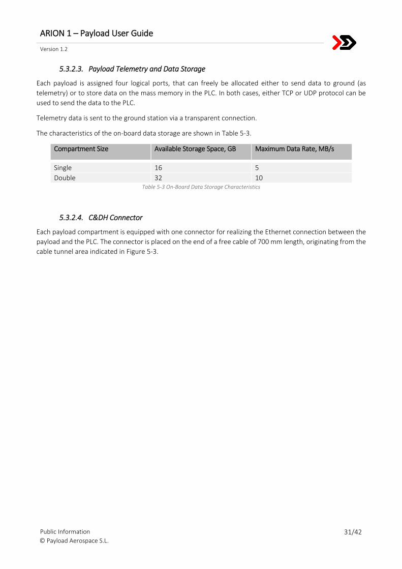
The characteristics of the on-board data storage are shown in Table 5-3.
Compartment Size Available Storage Space, GB Maximum Data Rate, MB/s
Single 16 5
Double 32 10 Table 5-3 On-Board Data Storage Characteristics
5.3.2.4. C&DH Connector
Each payload compartment is equipped with one connector for realizing the Ethernet connection between the
payload and the PLC. The connector is placed on the end of a free cable of 700 mm length, originating from the
cable tunnel area indicated in Figure 5-3.
ARION 1 – Payload User Guide
Version 1.2
Public Information 32/42 © Payload Aerospace S.L.
6. PAYLOAD EVNIRONMENTAL CONDITIONS
6.1. ATMOSPHERIC CONDITIONS
6.1.1. Payload Bay
The payload compartments are separately sealed airtight. This is done to protect the payload from damages
due to the sea air at the launch site (see section 6.1.2) and from sea water after splashdown.
The payload compartments are filled with 99.9% gaseous nitrogen once the payloads are sealed. The use of
other gases is possible and must be requested with PLD Space. As the payload compartments are sealed
independently from each other, each customer can decide when the associated compartment is sealed and
filled with nitrogen. The earliest possibility is right after the payload has been integrated into the payload bay,
so the payloads can already be tested under nitrogen environment. The latest possibility for sealing the payload
compartment is after all payloads passed the combined acceptance testing and the complete payload bay is
prepared for its transport to the launch site.
For the transport, the payload compartments stay closed and filled with nitrogen. While at the launch site, PLD
Space recommends limiting the time the payload compartments need to be opened (e.g. late access) as much
as possible to prevent the corrosive ambient air from entering.
6.1.2. Launch Site
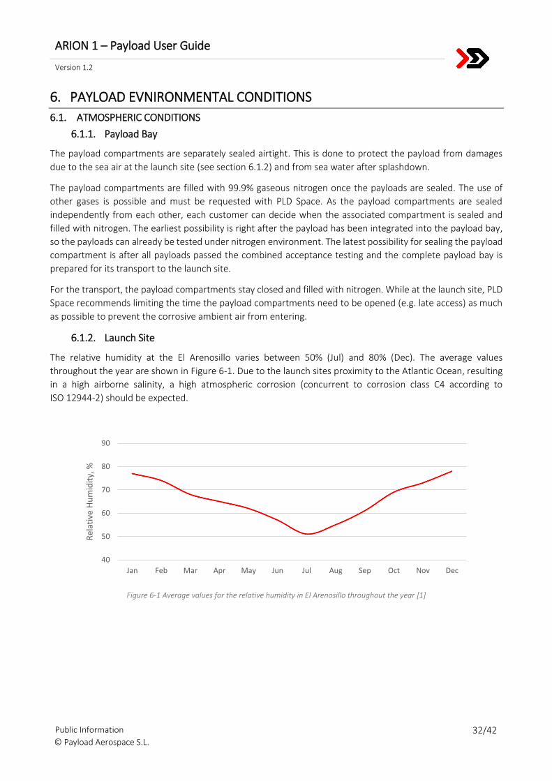
The relative humidity at the El Arenosillo varies between 50% (Jul) and 80% (Dec). The average values
throughout the year are shown in Figure 6-1. Due to the launch sites proximity to the Atlantic Ocean, resulting
in a high airborne salinity, a high atmospheric corrosion (concurrent to corrosion class C4 according to
ISO 12944-2) should be expected.
Figure 6-1 Average values for the relative humidity in El Arenosillo throughout the year [1]
40
50
60
70
80
90
Jan Feb Mar Apr May Jun Jul Aug Sep Oct Nov Dec
Rel
ativ
e H
um
idit
y, %
ARION 1 – Payload User Guide
Version 1.2
Public Information 33/42 © Payload Aerospace S.L.
6.2. THERMAL ENVIRONMENT
6.2.1. Pre-Flight
6.2.1.1. Payload Integration and Testing
The integration and final testing of the payloads is performed at the PLD Space Headquarters. The temperature
inside the integration hall and test facilities can vary from 20°C to 35 °C. Additional heating or cooling can be
provided in coordination with PLD Space.
6.2.1.2. Payload Transport
During the transport from the PLD Space Headquarters to the launch site, the temperatures inside the cargo
van varies between 15 °C and 30 °C, depending on the time of the year. The transport is usually realized in less
than a day.
6.2.1.3. Launch Preparations
For the final launch preparations, the ARION 1 rocket is kept inside the preparation hall at El Arenosillo as long
as possible in order to avoid the rocket heating up too much due to possible high outdoor temperatures. The
temperature inside the preparation hall can vary from 20°C to 35 °C.
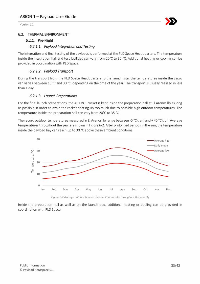
The record outdoor temperatures measured in El Arenosillo range between -5 °C (Jan) and + 45 °C (Jul). Average
temperatures throughout the year are shown in Figure 6-2. After prolonged periods in the sun, the temperature
inside the payload bay can reach up to 30 °C above these ambient conditions.
Figure 6-2 Average outdoor temperatures in El Arenosillo throughout the year [1]
Inside the preparation hall as well as on the launch pad, additional heating or cooling can be provided in
coordination with PLD Space.
0
10
20
30
40
Jan Feb Mar Apr May Jun Jul Aug Sep Oct Nov Dec
Tem
per
atu
re,
°C
Average high
Daily mean
Average low
ARION 1 – Payload User Guide
Version 1.2
Public Information 34/42 © Payload Aerospace S.L.
6.2.2. Flight
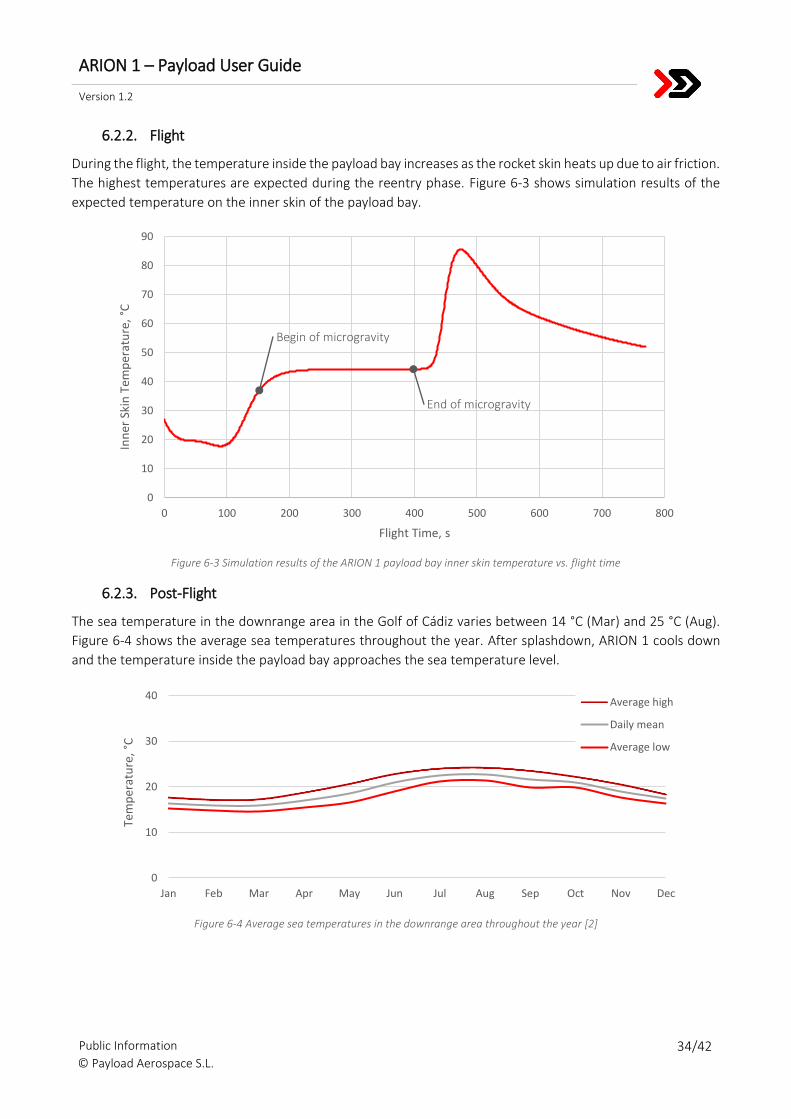
During the flight, the temperature inside the payload bay increases as the rocket skin heats up due to air friction.
The highest temperatures are expected during the reentry phase. Figure 6-3 shows simulation results of the
expected temperature on the inner skin of the payload bay.
Figure 6-3 Simulation results of the ARION 1 payload bay inner skin temperature vs. flight time
6.2.3. Post-Flight
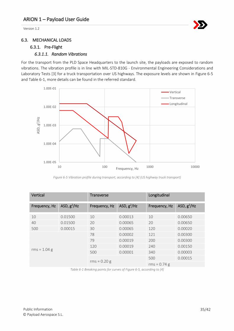
The sea temperature in the downrange area in the Golf of Cádiz varies between 14 °C (Mar) and 25 °C (Aug).
Figure 6-4 shows the average sea temperatures throughout the year. After splashdown, ARION 1 cools down
and the temperature inside the payload bay approaches the sea temperature level.
Figure 6-4 Average sea temperatures in the downrange area throughout the year [2]
0
10
20
30
40
50
60
70
80
90
0 100 200 300 400 500 600 700 800
Inn
er S
kin
Tem
per
atu
re,
°C
Flight Time, s
0
10
20
30
40
Jan Feb Mar Apr May Jun Jul Aug Sep Oct Nov Dec
Tem
per
atu
re,
°C
Average high
Daily mean
Average low
Begin of microgravity
End of microgravity
ARION 1 – Payload User Guide
Version 1.2
Public Information 35/42 © Payload Aerospace S.L.
6.3. MECHANICAL LOADS
6.3.1. Pre-Flight
6.3.1.1. Random Vibrations
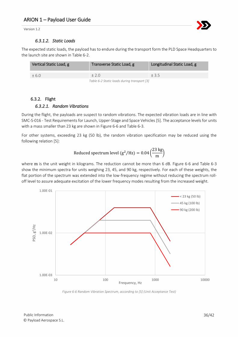
For the transport from the PLD Space Headquarters to the launch site, the payloads are exposed to random
vibrations. The vibration profile is in line with MIL-STD-810G - Environmental Engineering Considerations and
Laboratory Tests [3] for a truck transportation over US highways. The exposure levels are shown in Figure 6-5
and Table 6-1, more details can be found in the referred standard.
Figure 6-5 Vibration profile during transport, according to [4] (US highway truck transport)
Vertical Transverse Longitudinal
Frequency, Hz ASD, g2/Hz Frequency, Hz ASD, g2/Hz Frequency, Hz ASD, g2/Hz
10 0.01500 10 0.00013 10 0.00650
40 0.01500 20 0.00065 20 0.00650
500 0.00015 30 0.00065 120 0.00020
rms = 1.04 g
78 0.00002 121 0.00300
79 0.00019 200 0.00300
120 0.00019 240 0.00150
500 0.00001 340 0.00003
rms = 0.20 g 500 0.00015
rms = 0.74 g Table 6-1 Breaking points for curves of Figure 6-5, according to [4]
1.00E-05
1.00E-04
1.00E-03
1.00E-02
1.00E-01
10 100 1000 10000
ASD
, g2 /
Hz
Frequency, Hz
Vertical
Transverse
Longitudinal
ARION 1 – Payload User Guide
Version 1.2
Public Information 36/42 © Payload Aerospace S.L.
6.3.1.2. Static Loads
The expected static loads, the payload has to endure during the transport form the PLD Space Headquarters to
the launch site are shown in Table 6-2.
Vertical Static Load, g Transverse Static Load, g Longitudinal Static Load, g
± 6.0 ± 2.0 ± 3.5 Table 6-2 Static loads during transport [3]
6.3.2. Flight
6.3.2.1. Random Vibrations
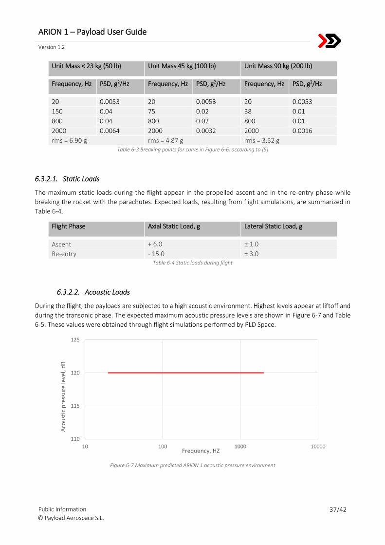
During the flight, the payloads are suspect to random vibrations. The expected vibration loads are in line with
SMC-S-016 - Test Requirements for Launch, Upper-Stage and Space Vehicles [5]. The acceptance levels for units
with a mass smaller than 23 kg are shown in Figure 6-6 and Table 6-3.
For other systems, exceeding 23 kg (50 lb), the random vibration specification may be reduced using the
following relation [5]:
Reduced spectrum level (g2 Hz)⁄ = 0.04 (23 kg
m)
where m is the unit weight in kilograms. The reduction cannot be more than 6 dB. Figure 6-6 and Table 6-3
show the minimum spectra for units weighing 23, 45, and 90 kg, respectively. For each of these weights, the
flat portion of the spectrum was extended into the low-frequency regime without reducing the spectrum roll-
off level to assure adequate excitation of the lower frequency modes resulting from the increased weight.
Figure 6-6 Random Vibration Spectrum, according to [5] (Unit Acceptance Test)
1.00E-03
1.00E-02
1.00E-01
10 100 1000 10000
PSD
, g2 /
Hz
Frequency, Hz
< 23 kg (50 lb)
45 kg (100 lb)
90 kg (200 lb)
ARION 1 – Payload User Guide
Version 1.2
Public Information 37/42 © Payload Aerospace S.L.
Unit Mass < 23 kg (50 lb) Unit Mass 45 kg (100 lb) Unit Mass 90 kg (200 lb)
Frequency, Hz PSD, g2/Hz Frequency, Hz PSD, g2/Hz Frequency, Hz PSD, g2/Hz
20 0.0053 20 0.0053 20 0.0053
150 0.04 75 0.02 38 0.01
800 0.04 800 0.02 800 0.01
2000 0.0064 2000 0.0032 2000 0.0016
rms = 6.90 g rms = 4.87 g rms = 3.52 g Table 6-3 Breaking points for curve in Figure 6-6, according to [5]
6.3.2.1. Static Loads
The maximum static loads during the flight appear in the propelled ascent and in the re-entry phase while
breaking the rocket with the parachutes. Expected loads, resulting from flight simulations, are summarized in
Table 6-4.
Flight Phase Axial Static Load, g Lateral Static Load, g
Ascent + 6.0 ± 1.0
Re-entry - 15.0 ± 3.0 Table 6-4 Static loads during flight
6.3.2.2. Acoustic Loads
During the flight, the payloads are subjected to a high acoustic environment. Highest levels appear at liftoff and
during the transonic phase. The expected maximum acoustic pressure levels are shown in Figure 6-7 and Table
6-5. These values were obtained through flight simulations performed by PLD Space.
Figure 6-7 Maximum predicted ARION 1 acoustic pressure environment
110
115
120
125
10 100 1000 10000
Aco
ust
ic p
ress
ure
leve
l, d
B
Frequency, HZ
ARION 1 – Payload User Guide
Version 1.2
Public Information 38/42 © Payload Aerospace S.L.
Frequency, Hz Acoustic pressure level, dB
20 120
2000 120 Table 6-5 Breaking points for curve of Figure 6-7
6.3.2.3. Shock Loads
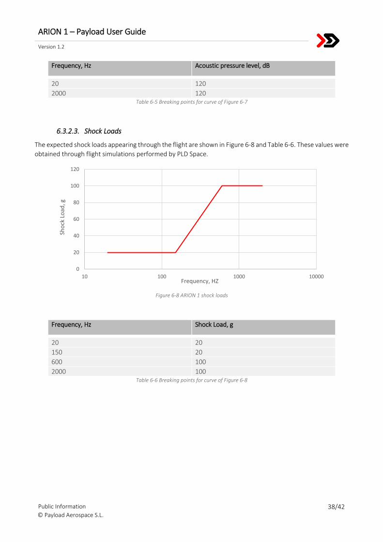
The expected shock loads appearing through the flight are shown in Figure 6-8 and Table 6-6. These values were
obtained through flight simulations performed by PLD Space.
Figure 6-8 ARION 1 shock loads
Frequency, Hz Shock Load, g
20 20
150 20
600 100
2000 100 Table 6-6 Breaking points for curve of Figure 6-8
0
20
40
60
80
100
120
10 100 1000 10000
Sho
ck L
oad
, g
Frequency, HZ
ARION 1 – Payload User Guide
Version 1.2
Public Information 39/42 © Payload Aerospace S.L.
7. SAFETY
7.1. SAFETY REQUIREMENTS
Payloads on ARION 1 and payload operations have to comply with the safety requirements of the used launch
site. These safety requirements usually concern systems and operations comprising hazardous electrical
systems, mechanical systems, chemicals, pressure systems, radiation sources (ionizing, non-ionizing/RF, optical
e.g. lasers) and a variety of other systems and operations. PLD Space assists the users in identifying hazardous
systems and operations within their payload.
To ensure adequate safety measures and procedures are implemented, information regarding these safety
critical elements has to be provided to the launch site authority. PLD Space acts as interface between ARION 1
payload users and the launch site authority. The entry point for this is the payload questionnaire, which is
enquiring about the most common safety hazards. Further information then has to be provided in the PDP.
7.2. WAIVERS
If any safety requirement cannot be satisfied by the payload, but the user still believes the payload is acceptable
for launch, a written request for waiver must be submitted to the launch site authority.
ARION 1 – Payload User Guide
Version 1.2
Public Information 40/42 © Payload Aerospace S.L.
8. DOCUMENT REFERENCES
8.1. LIST OF FIGURES
Figure 2-1 ARION 1 Rocket and Subsystems .........................................................................................................9
Figure 2-2 Location of the El Arenosillo Launch Site .............................................................................................9
Figure 2-3 GMV Logo ......................................................................................................................................... 10
Figure 2-4 Cut view of two single compartments inside a payload bay module ................................................ 11
Figure 2-5 Achievable Microgravity Time vs. Total Payload Mass ...................................................................... 12
Figure 2-6 Achievable Altitude vs. Total Payload Mass ...................................................................................... 12
Figure 2-7 Altitude vs. Flight Time for varying Payload Mass ............................................................................. 13
Figure 3-1 PLD Space Headquarters ................................................................................................................... 14
Figure 3-2 PLD Space Staff in the HQ Offices ..................................................................................................... 14
Figure 3-3 Floor Plan of the Rocket Assembly Hall inside the PLD Space HQ ..................................................... 15
Figure 3-4 Mobile Launch Ramp (laid down and elevated) ................................................................................ 16
Figure 3-5 Draft concept of ARION 1 Launch Complex ...................................................................................... 17
Figure 3-6 PLD Space’s Propulsion Test Facilities ............................................................................................... 18
Figure 3-7 TEPREL Engine test at PLD Space’s Propulsion Test Facilities in Teruel ............................................ 18
Figure 4-1 Nominal Arion 1 Mission Timeline .................................................................................................... 19
Figure 4-2 Payload Documentation Due Dates .................................................................................................. 21
Figure 4-3 ARION 1 Ballistic Flight Phase ........................................................................................................... 24
Figure 4-4 ARION 1 Trajectory when launched from El Arenosillo ..................................................................... 25
Figure 5-1 ARION 1 structure coordinate frame ................................................................................................ 26
Figure 5-2 Payload Envelope - Side View ........................................................................................................... 27
Figure 5-3 Payload Envelope - Top View ............................................................................................................ 27
Figure 5-4 Dimensions of the isogrid pattern machined in the payload bay bulkheads .................................... 28
Figure 5-5 Bulkhead Fitting Clearance Dimensions ............................................................................................ 28
Figure 5-6 Payload Bay Hatch Dimensions and Position. ................................................................................... 29
Figure 6-1 Average values for the relative humidity in El Arenosillo throughout the year [1] ........................... 32
Figure 6-2 Average outdoor temperatures in El Arenosillo throughout the year [1] ......................................... 33
Figure 6-3 Simulation results of the ARION 1 payload bay inner skin temperature vs. flight time .................... 34
Figure 6-4 Average sea temperatures in the downrange area throughout the year [2] .................................... 34
Figure 6-5 Vibration profile during transport, according to [4] (US highway truck transport) ........................... 35
Figure 6-6 Random Vibration Spectrum, according to [5] (Unit Acceptance Test) ............................................ 36

ARION 1 – Payload User Guide
Version 1.2
Public Information 41/42 © Payload Aerospace S.L.
Figure 6-7 Maximum predicted ARION 1 acoustic pressure environment ......................................................... 37
Figure 6-8 ARION 1 shock loads ......................................................................................................................... 38
8.2. LIST OF TABLES
Table 2-1 ARION 1 Baseline Data ..........................................................................................................................9
Table 4-1 ARION 1 Main Countdown Events ...................................................................................................... 23
Table 4-2 ARION 1 Flight Events......................................................................................................................... 24
Table 4-3 ARION 1 Recovery Timeline ................................................................................................................ 25
Table 5-1 Maximum payload mass single and double compartments ............................................................... 26
Table 5-2 Payload Power Supply – On-board Battery Current Limits and Capacity ........................................... 30
Table 5-3 On-Board Data Storage Characteristics .............................................................................................. 31
Table 6-1 Breaking points for curves of Figure 6-5, according to [4] ................................................................. 35
Table 6-2 Static loads during transport [3] ......................................................................................................... 36
Table 6-3 Breaking points for curve in Figure 6-6, according to [5] ................................................................... 37
Table 6-4 Static loads during flight ..................................................................................................................... 37
Table 6-5 Breaking points for curve of Figure 6-8 .............................................................................................. 38
Table 6-6 Breaking points for curve of Figure 6-9 .............................................................................................. 38
ARION 1 – Payload User Guide
Version 1.2
Public Information 42/42 © Payload Aerospace S.L.
9. BIBLIOGRAPHY
[1] Agencia Estatal de Meteorología, "Valores climatológicos normales. Huelva, Ronda Este," [Online].
Available:
http://www.aemet.es/es/serviciosclimaticos/datosclimatologicos/valoresclimatologicos?l=4642E&k=and.
[Accessed 07 March 2018].
[2] World Sea Temperature, "Huelva Sea Temperature," [Online]. Available:
https://www.seatemperature.org/europe/spain/huelva.htm. [Accessed 07 March 2018].
[3] US Department of Defense, MIL-STD-810G - Environmental Engineering Considerations and Laboratory
Tests, 15 April 2014.
[4] National Aeronautics and Space Administration, NASA-HDBK-7005 - Dynamic Environmental Criteria - NASA
Technical Handbook, 13 March 2001.
[5] Air Force Space Command, SMC-S-016 - Space and Missile Systems Center Standard - Test Requirements for
Launch, Upper-Stage and Space Vehicles, 5 September 2014.
Public Information 1/42 © Payload Aerospace S.L.
ARION 1 – Payload User Guide
Version 1.2, 08 June 2018
© Payload Aerospace S.L.
All contents of this document belong to PLD Space as the solely owner of its Intellectual Property exclusive
rights. Except third parties’ contents particularly referred, PLD Space has all exclusive rights thereto, and any
use of such contents is prohibited without its authorization.