Embed Size (px)
Citation preview

ARIADNE: Agnostic ReconfigurationIn A Disconnected Network Environment
Konstantinos Aisopos†§, Andrew DeOrio‡, Li-Shiuan Peh§, and Valeria Bertacco‡†Princeton University §Massachusetts Institute of Technology ‡University of Michigan
Abstract—Extreme transistor technology scaling is causingincreasing concerns in device reliability: the expected lifetime ofindividual transistors in complex chips is quickly decreasing, andthe problem is expected to worsen at future technology nodes.With complex designs increasingly relying on Networks-on-Chip(NoCs) for on-chip data transfers, a NoC must continue tooperate even in the face of many transistor failures. Specifically,it must be able to reconfigure and reroute packets around faultsto enable continued operation, i.e., generate new routing pathsto replace the old ones upon a failure. In addition to thesereliability requirements, NoCs must maintain low latency andhigh throughput at very low area budget.
In this work, we propose a distributed reconfigurationsolution named Ariadne, targeting large, aggressively scaled,unreliable NoCs. Ariadne utilizes up*/down* for fast routing athigh bandwidth, and upon any number of concurrent networkfailures in any location, it reconfigures to discover new resilientpaths to connect the surviving nodes. Experimental resultsshow that Ariadne provides a 40%-140% latency improvement(when subject to 50 faults in a 64-node NoC) over other on-chipstate-of-the-art fault tolerant solutions, while meeting the lowarea budget of on-chip routers with an overhead of just 1.97%.
Keywords-NoC; resilience; reconfiguration; distributed
I. INTRODUCTION
Aggressive transistor scaling continues to increase integra-
tion capacity with each new technology node. With more
transistors comes the need for modular communication ar-
chitectures. Networks-on-Chip (NoCs), which offer distributed
communication via a set of connected routers, are becoming
more popular, as indicated by some recent designs, such as
the Tile64 [4] and TERAFlops [30]. The NoCs of such many-
core chips have to meet tough latency and throughput targets,
in the face of stringent area and power budgets. Unfortunately,
as critical dimensions shrink, reliability degrades as well. This
highly scaled, unstable silicon demands new solutions that
can gracefully handle permanent failures, occurring due to
transistor wear-out, at any time during the life of the chip
[8]. As the sole medium of communication, it is critical that
a failure in the network does not cause an entire chip to fail.
Most current approaches for NoC reliability are only effec-
tive in overcoming a limited number of failures and specific
fault patterns. Yet, a large number of transistors can fail in a
many-core chip at advanced technology nodes [7, 8], resulting
in many faults in the NoC. In addition, the locations of
these faults are unpredictable and irregular in nature [11] and
can thus lead to deadlock-prone irregular network topologies.
Thus, any viable solution for failure-prone networks requires
that the surviving nodes coordinate to reconfigure and replace
the routing algorithm with a new one upon each new fail-
ure, by discovering the underlying topology and establishing
deadlock-free routes.Contributions. A fault-tolerant interconnect should address
three critical metrics: reliability, performance, and area. In this
work we propose Ariadne1, a novel network reconfiguration
algorithm, providing unlimited system robustness and high
performance, within a very low area budget. Ariadne is agnos-
tic to the underlying topology: it can operate on any irregular
topology resulting from an initial regular topology where any
number of links have failed. Ariadne discovers paths among
all connected nodes, and then utilizes up*/down* to provide
highly adaptive and deadlock-free routing. It achieves this
through a novel distributed algorithm implemented in hard-
ware. This algorithm is designed to minimize communication
among nodes, thus lowering its silicon area footprint. Ariadne
addresses the above critical metrics as follows:
• Reliability: Ariadne guarantees connectivity among all
surviving nodes in the network, in the face of unlimited
faults at any location. That is, if a path between two nodes
exists, the algorithm will enable at least one deadlock-free
route between them.
• Performance: During normal operation (after recovering
from faults), Ariadne achieves low latency and high
throughput routing without Virtual Channels (VCs). This
implies that no VC needs to be reserved for deadlock
avoidance; all VCs can be used by all available routing
paths, resulting in a 40%-140% latency improvement over
state-of-the-art fault tolerant solutions [14, 25] (latency
improvement measured at 50 faults in a 64-node NoC).
• Area: Our distributed design requires only a small
amount of hardware modifications and additional wiring
to realize reconfiguration. This results in a low 1.97%
area overhead over a baseline, non-reliable NoC.
This paper is organized as follows: Section II motivates
the need for resilient NoCs that can handle many wear-out
faults, and Section III presents the related work. Section IV
details Ariadne, while Section V discusses the architectural
modifications required to implement it. Then, Section VI offers
our experimental results. Section VII discusses how deadlock-
free execution is guaranteed in the face of runtime faults,
as well as off-chip implementations of up*/down*. Finally,
Section VIII concludes the paper.
1The name originates from Princess Ariadne from Greek mythology, whogave Theseus a ball of thread to help him find his way in the Minotaur’slabyrinth. Similarly, our algorithm helps packets find their way in thelabyrinth-like topology of a faulty network.

II. MOTIVATION
Recent studies project that there will be many transistor
failures during the lifetime of many-core chips fabricated at
advanced technology nodes. Researchers have characterized
the impact of technology scaling on device reliability in pro-
cessors [28] and Networks-on-Chips (NoCs) [3], and indicate
that the number of permanent failures is expected to increase.
Borkar of Intel expects that at future technology nodes 20%
of transistors in chip multiprocessors will be unusable due to
variations of the manufacturing process, while an additional
10% of transistors will eventually fail over the lifetime of the
chip due to wear-out [7, 8].
To demonstrate the architectural impact of such high number
of transistor failures in the NoC, we developed an architecture-
level fault model, similar to the fault model used in Vicis
[15], that maps gate-level injected faults to link-level faults.
Initially, we synthesize and place-and-route a router design
similar to that of [15], consisting of 20,413 gates. Then, we
inject faults to its netlist using a random distribution, weighted
by the area of each gate, in order to model the increased
vulnerability of complex gates comprising more transistors,
consistently with the breakdown patterns found experimentally
by Keane, et al. [19]. For statistical confidence, we inject a
total of 1,000 different fault configurations over a wide range
of simultaneous gate faults. Then, we test each faulty netlist
obtained to determine which links remained functional. This
way, our fault model does not only model wiring failures,
but also any failure within the router that results in non-
functional communication links. For instance, if a gate failure
disables a flit buffer of an output port, the corresponding
output link will also be marked as faulty. Figure 1 shows the
average number of link faults as a function of gate faults (error
Fig. 1: Link vs. gate faults.
bars showing min
and max) when
applying our fault
model to an 8x8
mesh of routers.
Note that even for
just 30 gate faults,
5 to 50 network
links are expected to
fail, resulting in a highly impaired network. These wear-out
link failures have no predictable pattern and can occur
anywhere on-chip [11], thus leading to highly irregular
network topologies.
In short, there is a strong need for low-overhead reliable
solutions for NoCs that are capable to deliver low latencyand high throughput in the presence of many irregular link
failures and potentially complete node failures, since routers
will become disconnected once all adjacent links have failed.
However, we note that the duration of the reconfiguration
process does not need to be optimal. A reconfiguration latency
even in the order of milliseconds will not affect overall
performance, since it only occurs upon a permanent link
failure.
III. RELATED WORK
There has been substantial research on resilient NoCs [11,
15]. Here, we focus on prior works that tackle routing in the
face of link failures. First, we classify them based on the type
of fault targeted and whether a bounded or unbounded number
of faults can be sustained. Then, we focus on solutions that
can tolerate unbounded faults without pattern constraints and
discuss current off-chip and on-chip approaches, indicating
how they differ in their design constraints. Our focus in this
paper is to achieve resilient routing on-chip in the face of manypermanent faults, by providing a solution that reconfigures the
network and updates the routing algorithm upon each failure.
Bounded number of faults. Early work on reliable routing
targeted few link failures, such as 1-fault tolerance in Dally’s
reliable router [12], (n-1) fault tolerant n-dimensional meshes
[16]. Works as in [17, 18, 29] leverage additional virtual
channels to work around a few link failures. There has also
been prior art that tackles the problem by flooding packets
to random neighbors, hoping that they will eventually reach
their destination [6, 24]. Such approaches result in very low
throughput during normal operation.
Unbounded number of faults with pattern constraints.
Other approaches place requirements on the configuration
of faults, requiring them to be contained in convex regions
[9, 31], L or T shape regions [9], or faulty polygons [20].
Oftentimes the faulty region must be expanded to include
non-faulty routers; as a result, non-faulty routers and links
are disabled only to satisfy the algorithm’s constraints.
Unbounded number of faults, no pattern constraints.
Table I qualitatively compares resilient routing algorithms
that can tolerate unbounded faults without pattern constraints,
based on critical evaluation metrics, which heavily depend on
the reconfiguration algorithm. Reconfiguration is the process
of generating a new routing algorithm (whenever a new link
fault is detected) to replace the current one. Given a faulty
topology, the reliability and performance of a routing algo-
rithm can be optimized with a sophisticated reconfiguration
algorithm, but complexity translates to high area overhead.
Off-chip reconfiguration algorithms run in software and can
perform powerful optimizations, but communicating the global
view of the surviving topology to a central node to run the re-
configuration software requires expensive dedicated hardware.
By contrast, on-chip solutions must be designed to meet tight
on-chip area budgets, thus achieving high performance or high
reliability is a challenge.
a) Off-chip solutions. Off chip networks, such as clusters
and Networks-Of-Workstations, first tackled the reliability
challenge of unconstrained faults. A number of resilient rout-
ing algorithms that can be applied to any irregular topology
(i.e., a topology that survived after a number of random
faults in network links) has been proposed in this domain,
including up*/down* (introduced in Autonet) [27], segment-
based routing [23], FX routing [26], L-turn [21], and smart-
routing [10]. During reconfiguration, the surviving topology
is communicated to a central node, which runs the recon-

reliability performance areabounded faults early work[12, 16], VCs[17, 18, 29] flooding [6, 24] limited n/a n/a
pattern constraints convex [9, 31], L or T [9], polygons [20] limited n/a n/aunbounded faults off-chip routing [10, 21, 23, 26, 27] high good excessive
without on-chip Immunet [25] high bad highpattern constraints routing Vicis [14] limited bad low
Ariadne (proposed) high good low
TABLE I: Resilient routing landscape. Qualitative comparison of resilient solutions.
figuration algorithm in software. Using global knowledge of
the functional links, the software computes new routing tables
and communicates them back to each node. As we discuss in
Section VII-C, centralized approaches lead to excessive area
overhead for on-chip routers (estimated at 23.2%).
b) On-chip solutions. On chip networks have a tight
area and power budget, necessitating simple router structures.
Reconfiguration is implemented completely in hardware and
thus must be achievable with a simple Finite State Machine
(FSM). There are two recent on-chip proposals that tackle the
problem of unconstrained faults: Immunet [25] and Vicis [15]:
Immunet [25] routes packets fully adaptively towards their
destinations, based on buffer availability. If necessary, packets
switch to a reserved escape VC that guarantees that they
will reach their destination and avoid faulty links. This VC
is aware of the fault locations and routes deterministically
in a ring through every node. Upon reconfiguration, a new
ring that connects all surviving nodes is formed with a single
broadcast, and all in-transit packets drain out via this ring,
before updating the routing tables. While the ring guarantees
delivery, it dramatically increases latency, since it must remain
active during normal operation to ensure deadlock freedom.
In addition, the design requires three routing tables per router,
resulting in high area (storage) overhead.
Vicis [15] proposes a low overhead routing algorithm [14] to
cope with an unbounded number of faults, by using a heuristic
solution that makes exceptions to the odd-even turn model to
maximize connectivity in meshes and tori. It utilizes the turn
model during fault-free operation, but upon the occurrence of
a fault, reconfiguration re-enables turns that were previously
disabled by the routing algorithm to re-connect nodes that have
been disconnected by the fault. As we show in Section VI,
these exceptions sometimes result in deadlocked routing paths,
especially in situations with large numbers of faults. Moreover,
its deterministic nature does not exploit all possible routes,
thus limiting performance during normal operation.
In this work, we propose the Ariadne reconfiguration algo-
rithm to realize up*/down* on-chip in a fully-distributed man-
ner. Up*/down* offers the unlimited robustness of Immunet,
and higher performance (low latency and high throughput)
than both Immunet and Vicis during normal operation, since
no virtual channels are restricted to deterministic routing.
Using a synchronization mechanism that leverages the global
clock to guarantee atomicity and minimize communication
among nodes, Ariadne reconfigures up*/down* (upon a fault)
in an area budget three times lower than Immunet and com-
parable to Vicis (Section VI-D). Its implementation requires
only a few gates and a single wire per port.
IV. ARIADNE ALGORITHM
Permanent transistor faults may cause link failures that
modify the topology of a NoC. Though the initial topology
of a NoC is usually regular, after a number of link failures,
nodes will be connected through a random irregular topology.
Ariadne is a reconfiguration algorithm that is invoked upon a
permanent link failure (e.g., due to transistor wear-out), and
it is agnostic to the topology, since it includes a discovery
phase of the underlying network to update the routing tables
with new deadlock-free paths. In a network of N nodes, the
reconfiguration procedure consists of N broadcasts, taking up
to N2 cycles. The procedure may run in a partially or fully
connected network, and guarantees that after N2 cycles every
node will know the output port(s) to route to any connected
destination2. Thereafter, network operation resumes normally.
Ariadne leverages up*/down* routing3, a deadlock-free
algorithm that can operate on any irregular topology [27].
Up*/down* requires each link to be assigned a direction: upor down. It then disallows those paths that include traversing
a down link followed by an up link. This way, all cyclic
dependencies are broken. In Section IV-A, we describe our
distributed reconfiguration algorithm that assigns a direction to
each link, thus allowing up*/down* routing to be applied after
reconfiguration. The algorithm then explores the new topology
and fills the routing tables with resilient paths connecting all
surviving nodes. A key cornerstone of our reconfiguration
algorithm is that it is fully distributed, relying on a single
atomic broadcast by each node to assign all link directions
and to explore the underlying topology, as we describe in
Section IV-B. This simple broadcast scheme makes for a very
lightweight hardware implementation (detailed in Section V).
A. Reconfiguration Algorithm
The reconfiguration algorithm works as follows: each node,
in turn, broadcasts a 1-bit reconfiguration flag to all nodes. The
first node to broadcast is the node that detected the fault in
the network, and it becomes the initiator (root node) of the
reconfiguration process. Upon receiving the reconfiguration
flag broadcasted from the root node, each node performs the
following actions (Figure 2):
2Reconfiguration delay is not a concern, since the performance overheadinduced by reconfiguration can only occur as many times as the link count,throughout the lifetime of the chip.
3Up*/down* is a routing algorithm designed for irregular networks, thusnot optimal for regular networks (i.e., a mesh). A potential optimization isto leverage DOR routing while the NoC is fault-free (regular), and switch toup*/down* once the first fault occurs. Note that transitioning from a routingalgorithm to another may introduce deadlocks, which can be prevented asdiscussed in Section VII-B.

Fig. 2: Ariadne reconfiguration algorithm: Actions per-
formed upon reception of the reconfiguration flag.
• Action1. Entering Recovery: enters recovery mode,
invalidates the old routing paths, and freezes head flits.
• Action2. Tagging Link Directions: marks all links ad-
jacent to the node either as up or down.
• Action3. Routing Table Update: informs routing table of
which port(s) can be used to reach the node that initiated
the broadcast.
• Action4. Flag Forwarding: forwards the reconfiguration
flag to its neighboring nodes.
After the root node has completed its first broadcast,
the remaining N-1 nodes in the N-node network broadcast
one-by-one. However, during these N-1 broadcasts, the flag
recipients will only perform the last two actions (Action3 and
Action4). Each action is described in detail below.
Action1: Entering Recovery. Upon receiving the flag for
the first time (initial broadcast from the root node), each
node invalidates its routing table, freezes the pipeline progress
of head flits, and sets its state as “recovering”. The state
will automatically switch back to “normal” in exactly N2
cycles, since the reconfiguration process is guaranteed to have
completed by then. Once the node gets into recovery mode,
each subsequent incoming flag will only invoke Actions 3, 4.Action2: Tagging Link Directions. Once a node gets into
recovery mode, up*/down* routing restrictions have to be
applied. In up*/down*, links towards the root node (connecting
to a node which is closer to the root) are up links, while links
away from the root are down links. Links to a node of equal
distance to the root (as the current node) can be either. During
the initial broadcast by the root, a port that receives a flag
connects to a node that is closer to the root (since the flag
arrived there first), thus it is marked as up. Similarly, a port
that forwards/sends a flag on is marked as down. The only
conflict occurs when neighboring nodes with equal distance
to the root node attempt to send the flag to each other in
the same cycle. In this case, each node will receive the flag
from a port while trying to send it to the same port. When
this happens, up*/down* suggests that the direction of the
corresponding link can be either up or down, so we set it based
on the statically assigned nodeIDs: the node with the higher
nodeID will mark the link as up; the other node will mark the
link as down (shown in the Action2 diagram of Figure 2).After this assignment, all the down→up turns are disabled.
This restriction inherits the deadlock freedom of up*/down*,
as explained in Section VII-A. Though a number of paths
are disabled, there is always at least one deadlock-free path
that connects all nodes reachable from the root node. That is
because the minimal route from any node to the root (up) and
from there to any destination node (down) is always available.Action3: Routing Table Update. During each broadcast,
the broadcasting node communicates to other nodes how it can
be reached. When nodes receive the broadcasted flag, they
record the ports where the flag was received from in their
own routing table, to learn how the broadcasting node can be
reached. This requires the broadcasts to spread via enabled
turns only, so that the recipient of the flag can follow the
opposite path to reach the broadcasting node. The third Action
of Figure 2 shows that the flag from node D’s broadcast arrives
to the current node via its North and East ports, thus these
ports are marked in the routing table to lead to D.Action4: Flag Forwarding. In the next cycle, the node
broadcasts the flag only to those port(s) from which it did not
receive a flag earlier and that correspond to enabled turns (a
flag received from up link(s) is never broadcasted to up links,
because this will enable a routing path with a down→up turn,
as shown in the last diagram of Figure 2). Since forwarding a
flag takes a single cycle, each broadcast will deterministically
complete in at most N cycles4.
4Each broadcast is bounded to N cycles. The worst case scenario occurswhen all nodes are connected in an open ring, and the longest broadcast fromone end to the other requires N-1 cycles.

Fig. 3: Example of Ariadne reconfiguration. Initial broadcast by root node and 5th broadcast by Node5.
Completion of Reconfiguration. Reconfiguration is de-
terministically completed within N2 cycles since each node
broadcasts once, and each broadcast takes at most N cycles.
During this time, all routing tables are updated with resilient
paths to any connected node, thus communication may be
resumed and all nodes set their state back to “normal”. After
this point, any node can initiate a new broadcast upon detection
of a link failure and invoke the reconfiguration process again.
The head flits can now proceed in the pipeline, but since routes
have changed (routing tables have been updated), they must
restart from the route compute stage to find an alternative port
that leads to the desired destination.
Walkthrough Example. An example of the reconfiguration
process is shown in Figure 3. In this figure, we show a 7-node
network connected in an irregular topology. Node1 detected
a link failure, and initiates a broadcast. Figure 3a shows
how each node receives the flag during the initial broadcast,
marks the link(s) the flag was received from as up (Action2),
fills the entry corresponding to the broadcasting node in its
routing table (Action3), and then forwards it to its neighbors
(Action4), while marking those link(s) as down (Action2).
Node2 and Node6 receive the flag during the 1st cycle and
forward it to each other during the 2nd cycle. To resolve this
conflict, the node with the higher NodeID (i.e., Node6) marks
the link as up and the other node (i.e., Node2) as down. We
note that there is an implicit unique node ordering, shown in
the table, which will be leveraged in our deadlock freedom
discussion in Section VII-A.
Each subsequent broadcast can only follow paths that are
consistent with the up*/down* restriction. As shown in Figure
3b, when Node5 is broadcasting, Node4 does not forward the
flag to its North port (1st cycle, Action4), because this would
result in Node0 following an illegal path to reach Node5 (the
Node0→Node4→Node5 turn is down→up). During Node5’s
broadcast, all nodes only perform Actions 3 and 4: they mark
which port they should follow to route to Node5 in their
own routing table, and then they forward the flag to all legal
directions. Note that all nodes can reach Node5 via the root
(up to the root Node1, then down to Node5). Also note that
some nodes may use multiple output ports to reach Node5
(e.g., Node3 can either use its West or South port, since
it received the flag from both ports during the 3rd cycle),
enabling adaptive routing. In this work, we only considered
minimal paths for simplicity in adaptive routing. Thus, nodes
that have already filled a routing table entry, ignore future
flags for the same broadcasting node (for example, Node4 and
Node6 do not record their North port as a potential path to
Node5 during the 3rd cycle, since this would lead to a non-
minimal route). At runtime, the port with the highest number
of available virtual channels among all valid (recorded) ports
is selected to balance traffic density.
B. Timing and Synchronization
Section IV-A presented the reconfiguration algorithm. What
has not been detailed so far is the timing of the reconfiguration:
How does each node know when to broadcast so that there
is no overlap between broadcasts? How does the recipient
of a broadcast know the broadcasting node, since the only
data broadcasted is a 1-bit flag? How do nodes know when
the reconfiguration is completed? If two nodes concurrently
detect a new fault, can they both become roots and initiate
a broadcast? This section deals with these timing issues by
introducing the notion of atomic broadcasts, where the cycle
number5 indicates the ID of the broadcasting node.
Atomic Broadcasts. The idea of atomic broadcasts is to
correlate the cycle number at which a broadcast is initiated to
the broadcasting node’s nodeID. Using the cycle number as
a common reference point, all nodes are assigned different
cycles for broadcasting, during which the remaining nodes
are prevented from broadcasting for a window of N cycles
(every broadcast is guaranteed to complete in N cycles, where
N is the number of nodes). Each node will have to wait
5We assume a single synchronized global clock across the entire system. Bythe term “cycle”, we refer to the count of the positive clock edges in a node(i.e., router and computation unit). It is not necessary that the communicationsystem is controlled by the same clock as the computation units, but it has tobe driven by a single clock.

Fig. 4: Router Architecture. Ariadne’s components shown shaded and expanded on the right part of the figure.
Fig. 5: Logic schematic for the building blocks of Ariadne’s reconfiguration algorithm.
for its slot to broadcast, but during that slot no other node
would be broadcasting, causing a collision. N slots need to
be provided for all N nodes to broadcast, with slots looping
around throughout execution. In other words, node(X)’s N-
cycle slot is always followed by node((X+1)modN)’s N-cycle
slot. The idea is similar to time-division multiplexing, where a
number of signals physically take turns to transfer data on the
same communication channel. Once the root node broadcasts,
every node will deterministically broadcast during its first
available slot; assuming that R is the root, nodes will broadcast
in the order: R, R+1, ..., N-1, 0, 1, ..., R-1. Since N slots
of N-cycles are required for the reconfiguration to complete,
reconfiguration requires precisely N2 cycles. Thus, all nodes
can resume operation N2 cycles after receiving the initial
broadcast, since by that time the process has been completed.
We note that if more than one node concurrently detects
a fault, only the one who first receives a broadcast slot
will become the root. The others will resign from becoming
the root once they receive the root’s broadcast. Our atomic
synchronization ensures that no two nodes will ever simultane-
ously become the root. Once reconfiguration has been initiated,
Ariadne will consider all detected faults in the network,
independently of the node that managed to become root.
Also, if a node is disconnected, it will not receive the root’s
broadcast, and will thus remain silent during its broadcast slot.
Other nodes will thus not fill the corresponding entry in their
routing tables (marking this node as unreachable).
V. ROUTER ARCHITECTURE
To evaluate our solution, we considered a baseline router
with a 5-stage pipeline6, as illustrated in the left part of Figure
4, with the following units: a route-compute unit to determine
the output port for a packet based on the final destination, a
virtual channel allocator to reserve a virtual channel in the
selected output port, a switch allocator to reserve the switch
bandwidth, and the switch itself.
To implement Ariadne, we added a few gates, registers,
and wires to the baseline router, as highlighted in the shaded
portion of Figure 4. Assuming four bi-directional ports (four
routing directions), Ariadne requires eight 1-bit wires (one for
each port’s direction) to transmit and receive the reconfigura-
tion flag from all directions. Ariadne logic consists of a 1-bit
status register to record the state (“recovering” or “normal”),
and one 1-bit register per port to remember the port’s direction
(up or down). The logic to update the status register (Action1),
to implement up*/down* (Action2), to fill the routing tables
(Action3), and to forward the reconfiguration flag (Action4)
are shown in the right part of Figure 4.
Figure 5 shows how these logic blocks are implemented.
The up*/down* logic (5a) updates the port direction registers:
receiving the flag from that port implies up, receiving it from
another port implies down, and sending and receiving at the
6Ariadne is orthogonal to the router pipeline. During normal operation,Ariadne is not active. During reconfiguration, the router pipeline is frozen,while Ariadne utilizes separate hardware to receive/broadcast flags.

Network Architecture (GARNET)network topology 8x8 2D meshmemory controllers 4 (chip corners)channel width 64 bitsrouter architecture 5-stage pipelinerouter ports, VCs 5, 2 (private)router buffers/port 5-flit/VC
System Configuration (GEMS)processors in-order SPARC corescoherence MOESI protocol
L1 caching private unified 32KB/nodeways:2 latency:3 cycles
L2 caching shared distributed 1MB/nodeways:16 latency:15 cycles
Simulation Input
synthetic traffic Uniform RandomTRranspose
benchmark suite PARSECpacket length 5simulation time 100K cyclessimulation warmup 10K cycles
TABLE II: Simulated system configured in GEMS/GARNET.
same time implies that the direction should be determined
by the routers’ NodeIDs. The logic that compiles the routing
tables (5b) sends to the routing unit the ID of the broadcasting
node together with the input port(s) from which the flag
was received, which indicate(s) the routing direction to the
broadcasting node. The broadcasting node is extracted from
logN bits of the cycle counter, as will be detailed below.
The routing tables consist of N Boolean entries (one for each
destination) of four bits (indicating the four output ports). We
note that during reconfiguration, all flags corresponding to
minimal paths to a specific destination node will concurrently
arrive at the same cycle; consequently, once a routing table
record is set, it cannot be overwritten in later cycles (i.e., if
the bit for at least one port is set to true in the routing table,
all future records for that same entry are ignored). Finally, the
logic responsible for forwarding the flag (5c) always forwards
the flag if received from an input port marked as down; if
the input port was marked as up, then it only forwards if the
corresponding output port is marked as down (Section IV-A).Extracting the broadcaster ID from the cycle number.
The hardware to implement this functionality is fairly simple.
The logN least significant bits of the cycle counter indicate
the cycle number of the current broadcast slot (1 to N).
The next logN most significant bits indicate which node is
authorized to broadcast during the current slot (1 to N). We
note that a cycle counter does not cost additional overhead,
since it is already available in the performance counters of
each processor core [1]. An example for N=4 is shown in
Figure 6, where the node that broadcasted the flag is indicated
by bit3bit2. A node can only initiate a broadcast at the first
cycle (bit1bit0=00) of its turn (bit3bit2=NodeID) and it is
guaranteed to complete this broadcast within 4 cycles (by
bit3bit2=NodeID and bit1bit0=11).
Fig. 6: Implementation of atomic broadcasts. Hardware that
leverages the global clock to guarantee atomicity in broadcasts
for an example 4-node (N=4) network.
VI. EXPERIMENTAL RESULTS
In this section, we evaluate Ariadne to determine its effec-
tiveness in faulty networks. We model faults with an accurate
gate-level fault model described in Section II, where we
map gate-level faults to link-level faults. Each simulation is
performed 1,000 times, each time using a different injected
fault configuration generated by our fault model (for 0 to 100
gate faults). We assume an ideal fault-detection mechanism,
since fault-detection is orthogonal to reconfiguration. In our
experimental setup, we evaluate the runtime performance
(Subsection VI-A), reliability (Subsection VI-B), reconfigu-
ration duration (Subsection VI-C), and hardware overhead
(Subsection VI-D) of our solution. Ariadne is implemented
in the Wisconsin Multifacet GEMS simulator [22] as part of
the GARNET network model [2]. Additionally, two state-of-
the-art routing algorithms are implemented for comparison:
the routing algorithm [14] of Vicis [15] and Immunet [25].
We configure GARNET to use an 8x8 mesh network (our
simulation infrastructure is shown in Table II) and simulate
synthetic traffic (Uniform Random and Transpose traffic), as
well as the PARSEC benchmark suite [5].
A. Performance Evaluation
We consider two metrics to measure the performance of
Ariadne on a faulty network: average latency and throughput.
Latency is defined as the delay experienced by a packet
from source to destination, while throughput demonstrates the
rate of packets delivered (per cycle) in the entire network.
First, we look at the zero-load latency for each of the three
routing algorithms (Vicis, Immunet, and Ariadne), reflecting
the steady-state latency of a lightly loaded network (0.01 flits
injected per cycle per node, well below saturation). Each data
point in Figure 7a is the average zero-load latency of 100
different topologies with the same number of faults.
We note that Ariadne’s latency is consistently the lowest, at
43 cycles on average, compared to 58 cycles for Immunet and
97 cycles for Vicis. At 50 faults, the difference increases, with
Ariadne showing a 43% latency improvement over Immunet
and a 142% improvement over Vicis. Moreover, we note that
the latency trend is strongly dependent on the algorithm,
but not greatly affected by the traffic type, as shown by
the closeness of the lines for each given algorithm. Vicis
shows some interesting behavior here, increasing in latency
as the number of faults increases. Upon further investigation,
we found that this was caused by the occasional deadlocks
encountered by the Vicis algorithm, which in turn trigger a

0
40
80
120
160
200
0 20 40 60 80 100
Injected Faults
Ave
rage
Lat
ency
(cyc
les)
Vicis, URVicis, TRAriadne, URAriadne, TRImmunet, URImmunet, TR
(a) Zero Load Latency. The average latency with a flit injection rateof 0.01, plotted for varying number of faults injected.
0
0.04
0.08
0.12
0.16
0.2
0 20 40 60 80 100
Injected Faults
Satu
ratio
n Th
roug
hput
(flit
s/no
de/c
ycle
) Vicis, URVicis, TRAriadne, URAriadne, TRImmunet, URImmunet, TR
(b) Saturation Throughput (flits/node/cycle) reaches a minimum at50 faults for all three algorithms. Then, it increases since packets routewithin small partitioned subnetworks.
Fig. 7: Performance on synthetic traffic
5,000-cycle timeout before dropping the deadlocked packets7.
We note that Ariadne and Immunet never drop a packet. Ari-
adne maintains a reasonable constant latency, outperforming
Immunet, since all of its virtual channels can route adaptively.
In contrast, Immunet has one escape virtual channel restricted
to route deterministically in a high-latency ring that goes
through all surviving nodes two times (both directions) on
average, independently of a packet’s destination.
Figure 7b plots the saturation throughput as a function of
faults. We used numerical analysis to find the throughput value
within a precision of 0.01. For each number of faults, we
performed this calculation for 100 different configurations.
Notice that for fault rates up to about 50, saturation throughput
decreases as the number of faults increases, as it can be
expected, since the number of available paths decreases. This
effect changes as the number of faults increases past 50,
when throughput begins to increase. That happens because
the network becomes partitioned, thus packets are routed a few
hops within small subnetwork partitions, so overall throughput
actually improves. For the same reason, the type of traffic does
not critically affect the saturation throughput at high number
of faults, since packets are restricted to route only within
7We did not implement a re-transmission mechanism for packets droppedby Vicis, but to keep the simulation going we instantly deliver the droppedpackets to their destination.
0
20
40
60
80
100
120
black
scho
les
body
track
dedu
pfer
ret
freqm
ine
strea
mcluste
r
swap
tions vip
sx2
64
avera
ge
Ave
rage
Lat
ency
(cyc
les)
AriadneVicisImmunet
(a) Latency for 50 faults. Each bar shows the average latency for eachbenchmark and algorithm. The average latencies are shown in the rightmostbar.
(b) Latency for variable number of faults. As the number of faultsincreases, Ariadne gives the best latency, while Vicis’ latency quicklyincreases due to deadlocks.
Fig. 8: Performance for PARSEC benchmarks
these subnetworks. Note that the impact of traffic type on
saturation throughput is not strong for Ariadne and Immunet.
However, since Vicis is based on the turn model, which has
naturally a higher saturation point, it more evenly spreads
random traffic, particularly in few-faults situations, where the
routing algorithm is closer to the turn model. We note that
although based on the turn model, Vicis is deterministic, and
uses a heuristic that chooses a minimal subset of available
turns to reduce the probability of deadlock occurrence.
In addition to synthetic traffic, we also investigate the
performance of our reconfigured network when running the
suite of PARSEC [5] benchmarks. First, we ran each PARSEC
benchmark on networks injected with 50 faults, the mid-
point of our fault injection range. Measuring the average
latency for packet delivery, we show the results for each
algorithm in Figure 8a. Exhibiting trends similar to the random
workload results, Ariadne outperforms Immunet and Vicis.
We also observe that benchmarks that scale poorly beyond
16 cores (we simulated a 64-core system), such as bodytrackand streamcluster [5], entail more frequent messages between
nearby nodes, resulting in lower average latency for Ariadne.
This occurs because fewer threads, mapped to near-by cores,
coordinate to complete the workload. In those cases, the
latency difference between Ariadne and Immunet is highest
(45%), since Immunet leverages a fixed virtual ring that snakes
through all nodes, so nodes that are physically close may have
20%
40%
60%
80%
100%
0 20 40 60 80 100
Injected Faults
Pack
et D
eliv
ery
Rat
e
Vicis URVicis TRAriadne URAriadne TRImmunet URImmunet TR
(a) Synthetic traffic.
(b) PARSEC benchmarks.
Fig. 9: Packet delivery rate. The percent of packets delivered
decreases as the number of faults increases. Undelivered
packets in Ariadne and Immunet are due to not fully connected
networks.
0%
4%
8%
12%
16%
20%
0 10 20 30 40 50 60 70 80 90 100
Injected Faults
Prob
abili
ty o
f Dea
dloc
k
AriadneVicisImmunet
Fig. 10: Probability of deadlock over different fault configu-
rations. Ariadne, Immunet are deadlock free (lines overlap at
the 0% value), while Vicis is not.
to route through many hops via the ring. On the other hand,
Vicis has its highest latency for benchmarks that scale well,
such as dedup and vips, since long communication patterns
are prone to creating cyclic routes and causing deadlocks.
In deepening our analysis while running PARSEC bench-
marks, we also evaluate performance as the number of faults
increases. Figure 8b shows the average latency over all PAR-
SEC benchmarks, as the number of injected faults ranges
from 0 to 100. Ariadne consistently provides the lowest
average latency. The performance difference is most significant
between Ariadne and Vicis under a large number of faults. We
note that this figure is very similar to the zero load latency of
synthetic traffic: that is because PARSEC benchmarks inject
very low network traffic leading to low network stress.
B. Reliability Evaluation
Faulty networks are frequently not fully connected. The
ability of an algorithm to maximize the connectivity of a faulty
network is critical, since if there is no viable route between
two locations, or if the routing algorithm has eliminated
the only possible route to avoid deadlock, the packet can
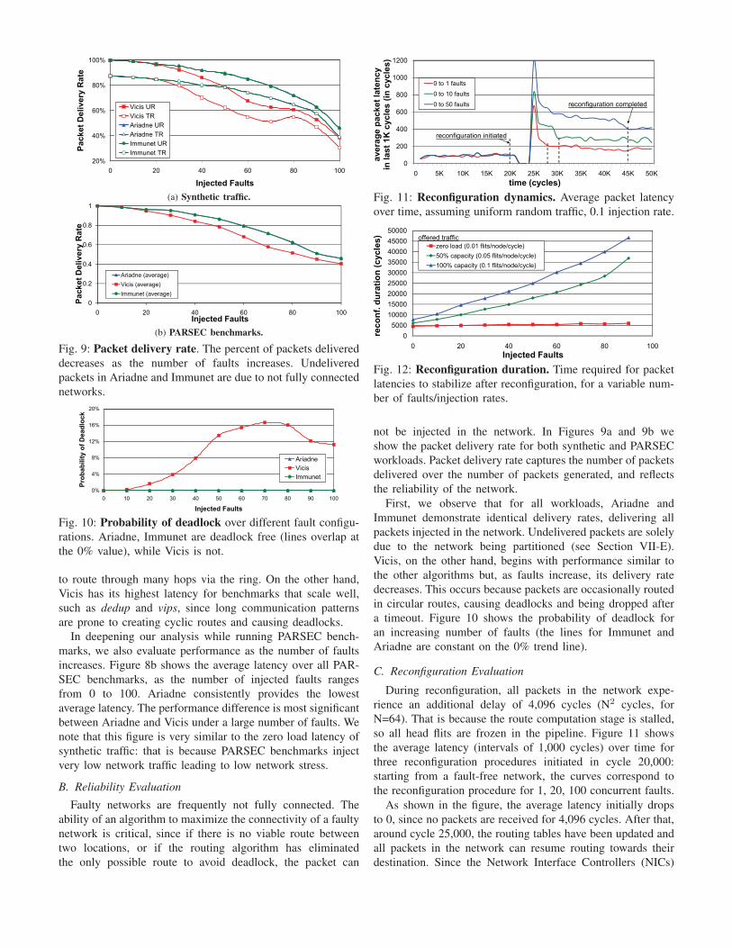
Fig. 11: Reconfiguration dynamics. Average packet latency
over time, assuming uniform random traffic, 0.1 injection rate.
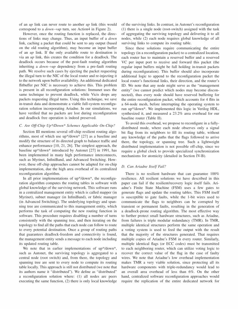
Fig. 12: Reconfiguration duration. Time required for packet
latencies to stabilize after reconfiguration, for a variable num-
ber of faults/injection rates.
not be injected in the network. In Figures 9a and 9b we
show the packet delivery rate for both synthetic and PARSEC
workloads. Packet delivery rate captures the number of packets
delivered over the number of packets generated, and reflects
the reliability of the network.
First, we observe that for all workloads, Ariadne and
Immunet demonstrate identical delivery rates, delivering all
packets injected in the network. Undelivered packets are solely
due to the network being partitioned (see Section VII-E).
Vicis, on the other hand, begins with performance similar to
the other algorithms but, as faults increase, its delivery rate
decreases. This occurs because packets are occasionally routed
in circular routes, causing deadlocks and being dropped after
a timeout. Figure 10 shows the probability of deadlock for
an increasing number of faults (the lines for Immunet and
Ariadne are constant on the 0% trend line).
C. Reconfiguration Evaluation
During reconfiguration, all packets in the network expe-
rience an additional delay of 4,096 cycles (N2 cycles, for
N=64). That is because the route computation stage is stalled,
so all head flits are frozen in the pipeline. Figure 11 shows
the average latency (intervals of 1,000 cycles) over time for
three reconfiguration procedures initiated in cycle 20,000:
starting from a fault-free network, the curves correspond to
the reconfiguration procedure for 1, 20, 100 concurrent faults.
As shown in the figure, the average latency initially drops
to 0, since no packets are received for 4,096 cycles. After that,
around cycle 25,000, the routing tables have been updated and
all packets in the network can resume routing towards their
destination. Since the Network Interface Controllers (NICs)

were not stalled during reconfiguration, all injection queues
will probably be full, resulting in increased contention right
after normal operation is resumed. This explains the peaks in
all three curves. The more the faults, the fewer the available
paths to connect nodes, thus the higher the latency that these
additional packets will experience (due to contention). Thus,
we note that curves corresponding to topologies with more
faults show longer times to drain packets generated during
reconfiguration, and also stabilize at a higher average latency,
since the new topology has lower capacity.
Figure 12 shows how the reconfiguration duration (time to
drain packets generated during reconfiguration and stabilize
to a new operating point) is affected by a variable number
of faults and different injection rates. A low injection rate
(zero load) will not generate a large number of packets during
reconfiguration, so even with more faults (fewer available
paths), there will be no congestion and the reconfiguration
duration will only slightly increase (less than 1,000 cycles).
For higher injection rates (comparable to the network capac-
ity), the number of faults causes contention that lasts from
4,000 cycles (few faults) to 40,000 cycles (many faults, highly
impaired network). Each point of the graph is an average over
ten faulty (but fully connected) topologies.
Note that we do not anticipate link faults to be sufficiently
frequent for reconfiguration duration to affect overall perfor-
mance. The purpose of this graph is to provide quantitative
insights on the reconfiguration process. Also, 50 concurrent
transistor failures are more realistic in future 1000-core de-
signs. The takeaway message of the figures is that Ariadne
is viable under many concurrent faults, with reconfiguration
duration scaling linearly.
D. Hardware Overhead
To determine the area impact of Ariadne in a router, we im-
plemented its hardware structures in Verilog HDL. Beginning
with a baseline 5-stage router design (Table II), we added the
Ariadne logic illustrated in Figure 4. We also implemented the
Vicis routing algorithm [14] and Immunet [25], whose major
hardware additions are summarized in Table III. The Vicis
routing algorithm requires the addition of a 64-entry static
routing table, as well as modified routing logic to perform the
routing heuristic. Immunet requires 3 additional routing tables
(an adaptive, a deterministic, and a small safe table) and 4
wires per link. Each design was synthesized using Synopsys
Design Compiler with an IBM 130nm target library. The
total area for the router equipped with Ariadne was measured
at 2.761mm2, which corresponds to an overhead of 1.97%
(baseline router’s area is 2.708mm2); this overhead is slightly
more than Vicis and three times less than Immunet.
wires routing tables overhead %overhead
Ariadne 1 adaptive 0.053mm2 1.97%
Vicis 1 deterministic 0.040mm2 1.48%
Immunet 4 adapt., determ, small 0.162mm2 5.98%
TABLE III: Additional hardware summary.
VII. DISCUSSION
In this section, we discuss how deadlock is avoided during
normal operation (when using up*/down* routing, subsec-
tion VII-A) and during reconfiguration (Ariadne algorithm,
subsection VII-B). Then, we elaborate on why existing off-
chip implementations of up*/down* would lead to excessive
overhead if adapted on-chip (subsection VII-C). Finally, we
explore whether Ariadne itself can fail (subsection VII-D) and
what happens when nodes disconnect (subsection VII-E).
A. Deadlock Avoidance (Normal Operation)
Up*/down* has been proven in the literature to be deadlock
free [27]. This is achieved by assigning a unique number
(node order) to each node and disabling all increasing-order
turns (down links), followed by decreasing order turns (uplinks). Note that the meaning of the terms “up” and “down”
is reversed. Since the orders are unique, there can be no cycle
without an increasing order followed by a decreasing order,
thus the paths are deadlock free. Here, we prove that the
way we assign link directions implies such a unique order.
Assuming N nodes, each with a pre-assigned nodeID [0,N),
and a root node with order 0, we define the order of each
NodeX that is connected to the root as:
order(X) = distance(root, X) * N + nodeID(X)The distance is measured in hops, and corresponds to the
minimal path that connects NodeX to the root. The table in
Figure 3 shows an example of this order assignment, where
Node1 is the root. This definition forces nodes that are closer
to the root node to always have a lower order than nodes that
are more distant (due to the multiplying factor N). For nodes
that are equally close to the root, their relative order is decided
based on their statically assigned nodeID (since the first term
of the equation above is the same): the node with the higher
nodeID is considered to have higher order. These are the only
two assumptions we used to assign a direction to each port,
thus our direction assignment complies with the unique node
ordering defined in the equation. Consequently, our nodes have
a unique order and our routing paths are deadlock free.
B. Deadlock Avoidance (Reconfiguration)
The reconfiguration process replaces one routing function
with another, by updating the routing tables in each node. As
described in Section IV-A, all head flits freeze during this
transition, thus the routing tables are not accessed and no
packet may compute its route using the new routing algorithm
until reconfiguration is completed. However, the body and tail
flits may follow the route that the head flit has already reserved
with the pre-fault routing paths. This section explores the
dependencies between the old and the new routing function,
which may create deadlocks once normal operation is resumed.
The necessary condition for deadlock is a cyclic dependency
of buffers, which is the result of routing in a cycle. During
normal operation, cyclic routing is prevented by up*/down* as
explained in VII-A, since a packet cached in an input buffer
of an up link can never route to another up link (this would
correspond to a down→up turn, see Action4 in Figure 2).
However, once the routing function is replaced, the direc-
tions of links may change. Thus, an input buffer of a downlink, caching a packet that could be sent to any output (based
on the old routing algorithm), may become an input buffer
of an up link. If the only available route to destination is
via an up link, this creates the condition for a deadlock. The
deadlock occurs because of the post-fault routing algorithm
inheriting a down→up dependency from a pre-fault routing
path. We resolve such cases by ejecting the packet requesting
the illegal turn to the NIC of the local router and re-injecting it
to the network upon buffer availability. An additional dedicated
flitbuffer per NIC is necessary to achieve this. This problem
is present in all reconfiguration solutions: Immunet uses the
same technique to prevent deadlock, while Vicis drops any
packets requesting illegal turns. Using this technique, we save
in-transit data and demonstrate a viable full-system reconfigu-
ration solution incorporating Ariadne. In our simulations, we
have verified that no packets are lost during reconfiguration
and deadlock free operation is indeed preserved.
C. Are Off-Chip Up*/Down* Schemes Applicable On-Chip?
Section III mentions several off-chip resilient routing algo-
rithms, most of which use up*/down* [27] as a baseline and
modify the structure of its directed graph to balance traffic and
enhance performance [10, 21, 26]. The simplest approach, the
baseline up*/down* introduced by Autonet [27] in 1991, has
been implemented in many high performance interconnects,
such as Myrinet, InfiniBand, and Advanced Switching. How-
ever, these off-chip approaches cannot be adapted for on-chip
implementation, due the high area overhead of its centralized
reconfiguration algorithm.
In all prior implementations of up*/down*, the reconfigu-
ration algorithm computes the routing tables in software with
global knowledge of the surviving network. This software runs
in a centralized management entity which is called mapper (in
Myrinet), subnet manager (in InfiniBand), or fabric manager
(in Advanced Switching). The underlying topology and span-
ning tree are communicated to this management entity, which
performs the task of computing the new routing function in
software. This procedure requires disabling a number of turns
consistently with the spanning tree, and then iterating on the
topology to find all the paths that each node can follow to route
to every potential destination. Once a group of routing paths
that guarantees deadlock-freedom and connectivity is found,
the management entity sends a message to each node including
its updated routing table.
We note that in earlier implementations of up*/down*,
such as Autonet, the surviving topology is aggregated to a
central node (root switch) and, from there, the topology and
spanning tree are sent to every node to compute its routing
table locally. This approach is still not distributed (we note that
its authors name it “distributed”). We define as “distributed”
a reconfiguration solution where: (1) all nodes are peers
executing the same function, (2) there is only local knowledge
of the surviving links. In contrast, in Autonet’s reconfiguration
(1) there is a single node (root-switch) assigned with the task
of aggregating the surviving topology and delivering it to all
nodes, while (2) each node requires global knowledge of all
surviving links to compute its routing table.
Since these solutions require communicating the entire
topology (in a reconfiguration packet) to a centralized location,
each router has to maintain a reserved buffer and a reserved
VC per input port to receive and forward this packet (the
regular input buffers might be full holding in-transit packets
during reconfiguration). This buffer should also incorporate
additional logic to append to the reconfiguration packet the
local router’s functional links, their direction, and the router’s
ID. We note that any node might serve as the “management
entity” (we cannot predict which nodes may become discon-
nected), thus every node should have reserved buffering for
the entire reconfiguration packet, which accounts for 4 flits in
a 64-node mesh, before interrupting the operating system to
run up*/down*. We implemented this logic in Verilog HDL,
synthesized it, and measured a 23.2% area overhead for our
baseline router (Table II).
To avoid this overhead, we propose to reconfigure in a fully-
distributed mode, where each node observes only a signal
bit flag from its neighbors to fill its routing table, without
any knowledge of the paths that the flags followed to arrive
there, the topology, or spanning tree. Such a lightweight
distributed implementation is not possible off-chip, since we
require a global clock to provide specialized synchronization
mechanisms for atomicity (detailed in Section IV-B).
D. Can Ariadne Itself Fail?
There is no resilient hardware that can guarantee 100%
resilience. All resilient solutions we have described in this
paper can fail if the resilient/recovery logic itself fails. Ari-
adne’s Finite State Machine (FSM) uses a few gates to
generate flags and update the routing tables. This FSM itself
is susceptible to gate faults, while the 1-bit wires used to
communicate the flags to neighbors can be corrupted by
transient or permanent faults, resulting in the generation of
a deadlock-prone routing algorithm. The most effective way
to further protect small hardware structures, such as Ariadne,
from failures is triple modular redundancy (TMR). In TMR,
multiple identical structures perform the same operation and
a voting system is used to feed the output with the result
that the majority of the structures generated. That requires
multiple copies of Ariadne’s FSM in every router. Similarly,
multiple identical flags (or ECC codes) must be transmitted
to each neighboring router, which can utilize voting logic to
recover the correct value of the flag in the case of faulty
wires. We note that Ariadne’s low overhead implementation
makes TMR a very viable solution, since protecting all its
hardware components with triple-redundancy would lead to
an overall area overhead of less than 6%. On the other
hand, centralized software reconfiguration approaches would
require the replication of the entire dedicated network for

communicating the reconfiguration information and of the
processor core executing it, which is not viable.
E. What Happens When Nodes Become Disconnected?
After a certain number of faults, there is a high probability
that the network will become partitioned (split into disjoint
clusters). Our reconfiguration solution will ensure that packet
delivery is guaranteed within each partition, but cannot transfer
packets among partitions. A network-only solution can identify
this problem, but cannot recover the system. In such cases, the
operating system will typically choose the largest partition of
nodes and migrate all active threads there, marking all nodes
that belong to other partitions as disconnected. To realize this
without interruption of execution, the state and data of each
active thread needs to be transferred from disconnected nodes
to nodes of the active partition, while no available paths to
connect these nodes exist in the underlying network. This
is a complementary problem, recently tackled by DRAIN
[13]. DRAIN is a recovery algorithm that uses dedicated
emergency links to save the architectural state and cached data
of disconnected nodes via cache-to-cache transfers.
VIII. CONCLUSIONS
We have presented Ariadne, an agnostic reconfiguration
algorithm for NoCs, capable of circumventing large numbers
of simultaneous faults, and able to handle unreliable future
silicon technologies. Ariadne utilizes up*/down* for high
performance and deadlock-free routing in irregular network
topologies that result from large numbers of faults, and offers
performance gains ranging from 40% to 140% (for 50 faults)
during normal operation, compared to state-of-the-art fault
tolerant solutions. It guarantees that if a path between two
nodes exists, the reconfiguration algorithm will enable at least
one deadlock-free path between them. Ariadne is implemented
in a fully distributed mode, since nodes coordinate to explore
the surviving topology, resulting in very simple hardware
and low complexity. At 1.97% area overhead, Ariadne is a
parsimonious solution for many-core processor designs of the
future, enabling a trade-off between performance and reliable
functionality on unreliable silicon.
ACKNOWLEDGMENT
The authors acknowledge the support of the Gigascale Sys-
tems Research Center and Interconnect Focus Center, research
centers funded under the Focus Center Research Program
(FCRP), a Semiconductor Research Corporation entity.
REFERENCES
[1] Intel core i7 processor. www.intel.com/products/processor/corei7.[2] N. Agarwal, T. Krishna, L.-S. Peh, and N. K. Jha. Garnet: A detailed
on-chip network model inside a full-system simulator. Proc. ISPASS,2009.
[3] K. Aisopos, C.-H. O. Chen, and L.-S. Peh. Enabling system-levelmodeling of variation-induced faults in networks-on-chip. In Proc. DAC,2011.
[4] S. Bell and et. al. Tile64 processor: A 64-core SoC with meshinterconnect. Proc. ISSCC, 2008.
[5] C. Bienia, S. Kumar, J. P. Singh, and K. Li. The PARSEC benchmarksuite: Characterization and architectural implications. In Proc. PACT,October 2008.
[6] P. Bogdan, T. Dumitras, and R. Marculescu. Stochastic communication:A new paradigm for fault-tolerant networks-on-chip. Hindawi VLSIDesign, 2007.
[7] S. Y. Borkar. Microarchitecture and design challenges for gigascaleintegration. Proc. MICRO, 2004.
[8] S. Y. Borkar. Designing reliable systems from unreliable components:The challenges of transistor variability and degradation. IEEE Micro,25(6):10–16, 2005.
[9] S. Chalasani and R. Boppana. Communication in multicomputers withnon-convex faults. IEEE Trans. Computers, 1997.
[10] L. Cherkasova, V. Kotov, and T. Rokicki. Fibre channel fabrics:Evaluation and design. In International Conference on System Sciences,1995.
[11] K. Constantinides, S. Plaza, J. Blome, B. Zhang, V. Bertacco, S. Mahlke,T. Austin, and M. Orshansky. Bulletproof: a defect-tolerant CMP switcharchitecture. Proc. HPCA, Feb 2006.
[12] W. J. Dally, L. R. Dennison, D. Harris, K. Kan, and T. Xanthopoulos.The reliable router: A reliable and high-performance communicationsubstrate for parallel computers. In Proc. PCRCW, 1994.
[13] A. DeOrio, K. Aisopos, V. Bertacco, and L.-S. Peh. DRAIN: Distributedrecovery architecture for inaccessible nodes in multi-core chips. In Proc.DAC, 2011.
[14] D. Fick, A. DeOrio, V. Bertacco, D. Sylvester, and D. Blaauw. A highlyresilient routing algorithm for fault-tolerant NoCs. Proc. DATE, 2009.
[15] D. Fick, A. DeOrio, J. Hu, V. Bertacco, D. Blaauw, and D. Sylvester.Vicis: a reliable network for unreliable silicon. In Proc. DAC, pages812–817, 2009.
[16] C. J. Glass and L. M. Ni. Fault-tolerant wormhole routing in mesheswithout virtual channels. IEEE Trans. Parallel and Distributed Systems,7(6), 1996.
[17] M. E. Gomez, J. Duato, J. Flich, P. Lopez, A. Robles, N. A. Nordbotten,O. Lysne, and T. Skeie. An efficient fault-tolerant routing methodologyfor meshes and tori. IEEE Computer Architecture Letters, 3(1), 2004.
[18] C.-T. Ho and L. Stockmeyer. A new approach to fault-tolerant wormholerouting for mesh-connected parallel computers. IEEE Trans. Computers,53(4), 2004.
[19] J. Keane, S. Venkatraman, P. Butzen, and C. Kim. An array-based testcircuit for fully automated gate dielectric breakdown characterization.In IEEE Custom Integrated Circuits Conference, pages 121–124, 2008.
[20] S.-P. Kim and T. Han. Fault-tolerant wormhole routing in mesh withoverlapped solid fault regions. Parallel Computing, 23(13), 1997.
[21] M. Koibuchi, A. Funahashi, A. Jouraku, and H. Amano. L-turn routing:An adaptive routing in irregular networks. In International Conferenceon Parallel Processing, 2001.
[22] M. Martin, D. Sorin, B. Beckmann, M. Marty, M. Xu, A. Alameldeen,K. Moore, M. Hill, and D. Wood. Multifacet’s general execution-drivenmultiprocessor simulator (GEMS) toolset. ACM SIGARCH ComputerArchitecture News, 33(4), 2005.
[23] A. Mejı́a, J. Flich, and J. Duato. Segment-based routing: An efficientfault-tolerant routing algorithm for meshes and tori. In Proc. IPDPS,2006.
[24] M. Pirretti, G. Link, R. Brooks, N. Vijaykrishnan, M. Kandemir, andM. Irwin. Fault tolerant algorithms for network-on-chip interconnect.In Proceedings of the IEEE Computer Society Annual Symposium onVLSI, pages 46–51, 2004.
[25] V. Puente, J. A. Gregorio, F. Vallejo, and R. Beivide. Immunet: A cheapand robust fault-tolerant packet routing mechanism. ACM SIGARCHComputer Architecture News, 32(2), 2004.
[26] J. C. Sancho, A. Robles, and J. Duato. A flexible routing scheme fornetworks of workstations. In Proc. HiPC, 2000.
[27] M. Schroeder, A. Birrell, M. Burrows, H. Murray, R. Needham, T. Rode-heffer, E. Satterthwaite, and C. Thacker. Autonet: a high-speed, self-configuring local area network using point-to-point links. IEEE Journalon Selected Areas in Comm., 9(8), 1991.
[28] J. Srinivasan, S. Adve, P. Bose, and J. A. Rivers. The impact oftechnology scaling on lifetime reliability. Proc. DSN, pages 177–186,2004.
[29] C.-C. Su and K. G. Shin. Adaptive fault-tolerant deadlock-free routingin meshes and hypercubes. IEEE Trans. Computers, 45(6), 1996.
[30] S. R. Vangal et al. An 80-tile sub-100-W teraflops processor in 65-nmCMOS. IEEE Journal of Solid-State Circuits, 2008.
[31] J. Wu. A fault-tolerant deadlock-free routing protocol in 2D meshesbased on odd-even turn model. IEEE Trans. Computers, 52(9), 2003.