Embed Size (px)
Citation preview

Aria Jellyfish - A.JF_A01 rev. 1.1_01/02/2019
www.plhitalia.com
Aria Jellyfish cod. A.JF_A01
© 2019 - epic srl - All rights reserved Page | 141
Technical specifications
Voltage range and frequency 110 - 230 V ~ 100 - 240 V~ (1 VA) 50-60 Hz
Voltage range 24 V –⃨ 18 - 30 V –⃨ (1W)
Input: Dry contact 4 NO to ground and pass through
Output: Transistor 4 (100mA and 30V –⃨ max); open-collector to GND; control
of inductive load allowed (with relays)
Feedback Led white (output) and blue (input) on board
Maximum output radio transceiver power: 2,4...2,483 Ghz +4 dBm
Range (depending on the surrondings) up to 15 m
Contains FCC ID: 2ALA3-CBM002A
Contains IC 22496-CBM002A
Wiring and connections terminal block wires max 1,5 mm2
Dimensions: 90,0 x 52,5 x 58,0 mm
Weight: 140 g
Degree of protection: IP20
Ambient temperature, ta: - 20 … + 45 °C
Max. case temperature, tc: + 65 °C
Max. relative humidity: 0...80%, non-cond.
Mark and regulations
General description
Bluetooth controllable, Casambi enabled, DIN RAIL (4 modules) 4 input 4 output interface, with
feedback led and multivoltage power supply. It can be connected, only by qualified professionals.
Can be controlled via PLH Aria keypads (PLH Neo Lighter, PLH Neo, PLH MakeUp Aria), and with
Casambi app available for iOs (iPhone 4S or later, iPad 3 or later, iPod Touch 5th gen or later) and
Android devices (Android 4.4 KitKat or later devices produced after 2013 with full Bluetooth 4.0
support).
Casambi Profile
5081 OUT: 4 Switch (relais bistable) - 0 Push button (relais monostable) IN: 4 dry contact
5082 OUT: 3 Switch (relais bistable) - 1 Push button (relais monostable) IN: 4 dry contact
5083 OUT: 2 Switch (relais bistable) - 2 Push button (relais monostable) IN: 4 dry contact
5084 OUT: 1 Switch (relais bistable) - 3 Push button (relais monostable) IN: 4 dry contact
5085 OUT: 0 Switch (relais bistable) - 4 Push button (relais monostable) IN: 4 dry contact
5975 OUT: 4 Pwm IN: 4 dry contact
www.plhitalia.com
Aria Jellyfish cod. A.JF_A01
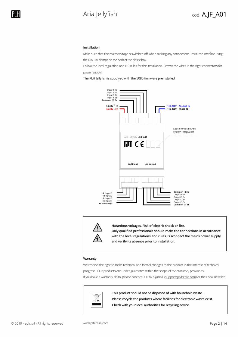
Installation
Make sure that the mains voltage is switched off when making any connections. Install the interface using
the DIN Rail clamps on the back of the plastic box.
Follow the local regulation and IEC rules for the installation. Screws the wires in the right connectors for
power supply.
The PLH Jellyfish is supplyed with the 5085 firmware preinstalled
Warranty
We reserve the right to make technical and formal changes to the product in the interest of technical
progress. Our products are under guarantee within the scope of the statutory provisions.
If you have a warranty claim, please contact PLH by e@mail ([email protected]) or the Local Reseller.
© 2019 - epic srl - All rights reserved Page | 142
Hazardous voltages. Risk of electric shock or fire. Only qualified professionals should make the connections in accordance with the local regulations and rules. Disconnect the mains power supply and verify its absence prior to installation.
!
6b 24V (-)6a 24V (+)
110-230V ~ Neutral 1a110-230V ~ Phase 1b
Input 1 2aInput 2 2bInput 3 2cInput 4 2d
Common (-) 2e
Common (-) 3aOutput 4 3bOutput 3 3cOutput 2 3dOutput 1 3eCommon (+) 3f
4e Input 14d Input 24c Input 34b Input 4
4a Common (-)
Led outputLed input
Aria - Jellyfish - A.JF_A01
–⃨–⃨
Space for local ID by system integrators
This product should not be disposed of with household waste.
Please recycle the products where facilities for electronic waste exist.
Check with your local authorities for recycling advice.
Please note!• The device may only be opened and installed according to
the circuit diagram on the device or these instructions by a qualified electrician. The existing safety regulations must be observed.
• Appropriate installation measures must be taken to achieve the requirements of protection class II.
• This independently mountable electromechani-cal or electronic device is designed for controlling the temperature in dry and enclosed rooms only under normal conditions.
• The device confirms to EN 60730, it works according opera-ting principle 1C.
• The permissible relative humidity of max. 95% must not be exceeded. Condensation is to be avoided.
• When starting up the room temperature controller, it must be noted that the thermo-bimetal requires a certain period of time to adapt itself to the room temperature. The switching point will therefore deviate from the room tem-perature immediately after installation or after switching off the night set-back. The switching point accuracy is ensured after approx. 1 to 2 hours of operation.
To heat up faster in the beginning and shorten the com-pensation time in the beginning, we recommend setting the room temperature higher than actually desired. After attaining the temperature, the temperature setting can be set back to the desired setpoint value.
Applications• The room temperature controller controls the temperature
in closed rooms, such as apartments, schools, halls, work-shops, etc. subject to normal ambient conditions.
Installation location• Preferably opposite the heating source on an inside wall.
radia
tor
radiator
RoomTemperature Controller
• Installation height: approx. 1.5 m above the floor• Avoid outside walls and air drafts originating from windows
and doors.• Please observe that the normal convection air of the room
must be able to reach the controller without hindrance. The controller should therefore not be installed between shelves, behind curtains or be covered in any way.
• Heat from other sources has a negative influence on cont-roller accuracy.
Therefore you should avoid:
direct sunlight, installation in the vicinity of TVs, radios, heaters, lamps, chimneys, and heating ducts.
• Even a dimmer creates heat! If the controller and a dimmer are installed in a shared
switch frame, the devices should be placed as far apart from each other as possible. If the devices are installed above each other, the controller must be below the dimmer on the bottom.
Installation on 58mm flush-type box (DIN 49 073)
a) Remove casing cover: - Pull off the adjustment knob - Loosen the cover screw - Pull off the coverb) Electrical connection according to circuit diagram
(see below).c) Mount the device onto the socket using the thread-forming
tapping screws for flush-type boxes.d) Mount the casing cover with switch frame.The cover must latch into the bottom part of the casing before tightening the screw. - Push the adjustment knob back onTo facilitate dismantling, the casing cover and switch frame should be removed together.
Electrical connectionConnect all lines exactly as shown in the relevant circuit diagram.Please observe that the neutral conductor N is connected to terminal N. If this is not the case, large temperature deviations will result since the controller will not be able to function properly.Conductor cross-section: 1 mm2 to 2.5 mm2 solid conductorNo protective-conductor terminal is required since the device is completely insulated.
Brief description in the circuit diagramL = outer conductor (phase)N = neutral conductor (previously Mp)> = terminal for clock signal for
temperature set-backU = heating load terminalP = cooling load terminalRF = resistance for thermal feedbackTA = resistance for night set-back of room temperature
Technical dataType 2026.. 2030.. 2031..Temperature range 5…30 °C 5…30 °C 5…30 °CRated voltage AC 250 V AC 250 V AC 24 VRated current (cos ϕ = 0,6) U heating P cooling
10 (4) A 5 (2) A
10 (4) A–
(DC 24V)10 (4) A–
Switching capacity U heating P cooling
2,2kW1,1kW
2,2kW–
240 W*–
Switching temp. diff. app. 0,5 K app. 0,5 K app. 0,5 KNight set-back – app. 4 K app. 4 K
*At DC max. 100 W
For all devices:Degree of pollution 2Calculation impulse voltage 4 kVTemperature for the Ball compression test 75 ± 2 °CVoltage and Current for the for purposes of interfernce measurements
230 V, 10 A
Order No.: 2030 .. Room temperature controller 250 V with NC contact, On/Off switch and LED
Order No.: 2031 .. Room temperature controller 24 V with NC contact, On/Off switch and LED
Note: LED On = controller active
Order No.: 2026 .. Room temperature controller 250 V with changeover contact
Narrowing down the temperature setting range
The controller is factory-set to a maximum setting range of 5 °C to 30 °C (see Fig. 1).There are 2 ring gauges in the adjustment knob. These ring gauges can be used to narrow down the temperature setting range as required, for example to a range of 8 °C to 23 °C.
Setting procedure:
1. Select the temperature limits: Example: max. 23°C min. 8°C2. Note! First turn the adjustment knob to the approximate
average value in the middle of the desired setting range. Example: The average value between 8°C and 23°C is
approx. 15°C3. Then pull off the adjustment knob.4. Set the red ring gauge to the max. temperature limit.
Example: 23°CRotate counter-clockwise. The numbers on the outside of the scale are valid! Place the tip of a pen into the hole and rotate the red ring counter-clockwise to 23°C (max. scale Fig. 2).5. Set the blue ring gauge to the minimum temperature limit. Example: 8°CRotate clockwise. The numbers on the inside of the scale are valid! Place the tip of a pen into the hole and rotate the blue ring to 8°C (min. scale Fig. 3).6. Push the adjustment knob back on:The indicator must be approximately in the center of the new setting range; see 2. Example: approx. 15°C
Fig. 1
The controller is suppliedwith this settingFull range:5°C to 30°C
Fig. 2
Red gauge ring (max.)set in direction of arrowto 23°C
Fig. 3
Blue gauge ring (min.)set in direction of arrowto 8°C
Temperature setting scaleswith flag digits
P = approx. 5°C = approx. 20°C
2 = approx. 10°C 5 = approx. 25°C
3 = approx. 15°C 6 = approx. 30°C
Symbols OFF
ON
ê permanently set temperature
ë permanently set set-back temperature
N switch-over between day and night temperature controlled by time switch
WarrantyWe reserve the right to make technical and formal changes to the product in the interest of technical progress. Our products are under guarantee within the scope of the statutory provisions. If you have a warranty claim, please contact the point of sale or ship the device postage free with a description of the fault to the appropriate regional representative.
Operating Instructions
RoomTemperature ControllerOrder No. 2026 .., 2030 .., 2031 ..
U 46
893
102
297
6-2
970
9182
000
This product should not be disposed of with household waste.Please recycle the products where facilities for electronic waste exist. Check with your local authorities for recycling advice.
www.plhitalia.com
Aria Jellyfish cod. A.JF_A01
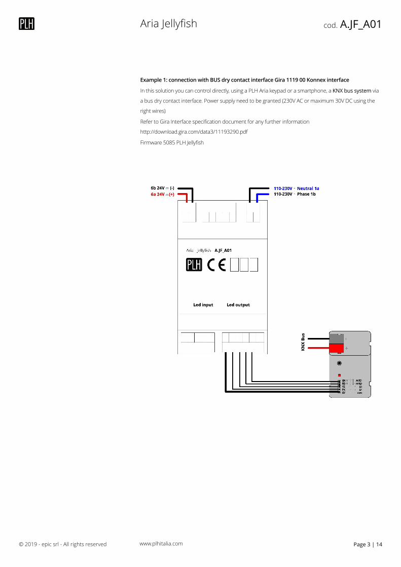
Example 1: connection with BUS dry contact interface Gira 1119 00 Konnex interface
In this solution you can control directly, using a PLH Aria keypad or a smartphone, a KNX bus system via
a bus dry contact interface. Power supply need to be granted (230V AC or maximum 30V DC using the
right wires)
Refer to Gira Interface specification document for any further information
http://download.gira.com/data3/11193290.pdf
Firmware 5085 PLH Jellyfish
© 2019 - epic srl - All rights reserved Page | 143
–⃨–⃨
www.plhitalia.com
Aria Jellyfish cod. A.JF_A01
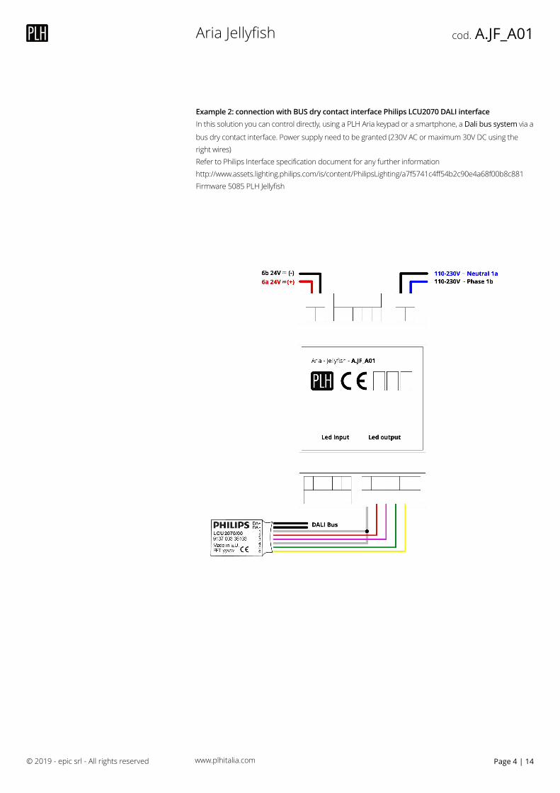
Example 2: connection with BUS dry contact interface Philips LCU2070 DALI interface In this solution you can control directly, using a PLH Aria keypad or a smartphone, a Dali bus system via a
bus dry contact interface. Power supply need to be granted (230V AC or maximum 30V DC using the right wires) Refer to Philips Interface specification document for any further information http://www.assets.lighting.philips.com/is/content/PhilipsLighting/a7f5741c4ff54b2c90e4a68f00b8c881 Firmware 5085 PLH Jellyfish
© 2019 - epic srl - All rights reserved Page | 144
–⃨–⃨–⃨
www.plhitalia.com
Aria Jellyfish cod. A.JF_A01
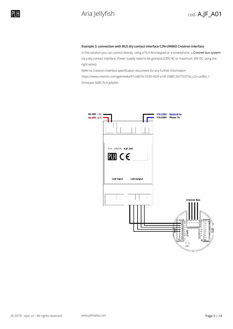
Example 3: connection with BUS dry contact interface C2N-UNI8IO Crestron interface
In this solution you can control directly, using a PLH Aria keypad or a smartphone, a Cresnet bus system
via a dry contact interface. Power supply need to be granted (230V AC or maximum 30V DC using the
right wires)
Refer to Crestron Interface specification document for any further information
https://www.crestron.com/getmedia/41ce847e-5535-492f-a1df-298812b77537/ss_c2n-uni8io_1
Firmware 5085 PLH Jellyfish
© 2019 - epic srl - All rights reserved Page | 145
–⃨–⃨
www.plhitalia.com
Aria Jellyfish cod. A.JF_A01
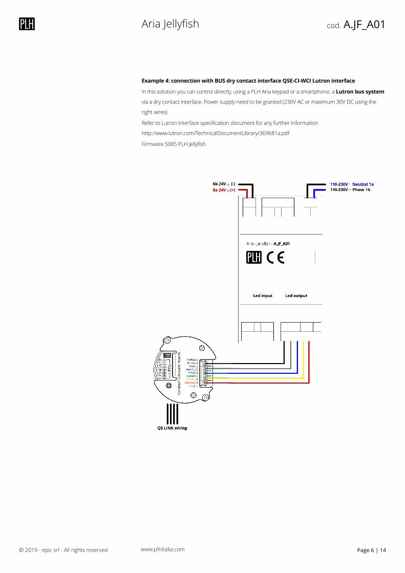
Example 4: connection with BUS dry contact interface QSE-CI-WCI Lutron interface
In this solution you can control directly, using a PLH Aria keypad or a smartphone, a Lutron bus system
via a dry contact interface. Power supply need to be granted (230V AC or maximum 30V DC using the
right wires)
Refer to Lutron Interface specification document for any further information
http://www.lutron.com/TechnicalDocumentLibrary/369681a.pdf
Firmware 5085 PLH Jellyfish
© 2019 - epic srl - All rights reserved Page | 146
–⃨–⃨
www.plhitalia.com
Aria Jellyfish cod. A.JF_A01
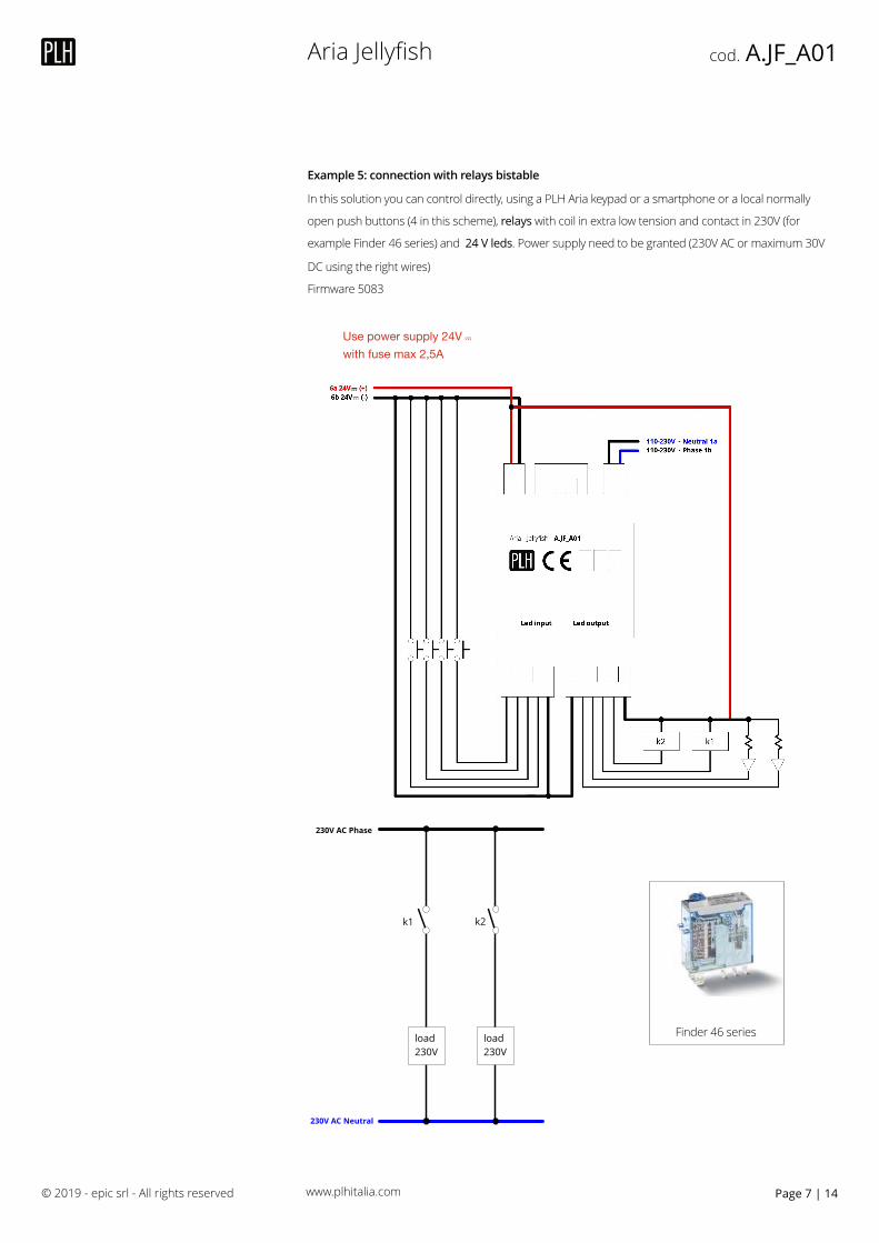
Example 5: connection with relays bistable
In this solution you can control directly, using a PLH Aria keypad or a smartphone or a local normally
open push buttons (4 in this scheme), relays with coil in extra low tension and contact in 230V (for
example Finder 46 series) and 24 V leds. Power supply need to be granted (230V AC or maximum 30V
DC using the right wires)
Firmware 5083
© 2019 - epic srl - All rights reserved Page | 147
Finder 46 series
k1 k2
230V AC Phase
230V AC Neutral
load 230V
load 230V
Use power supply 24V –⃨ with fuse max 2,5A
–⃨–⃨–⃨
www.plhitalia.com
Aria Jellyfish cod. A.JF_A01
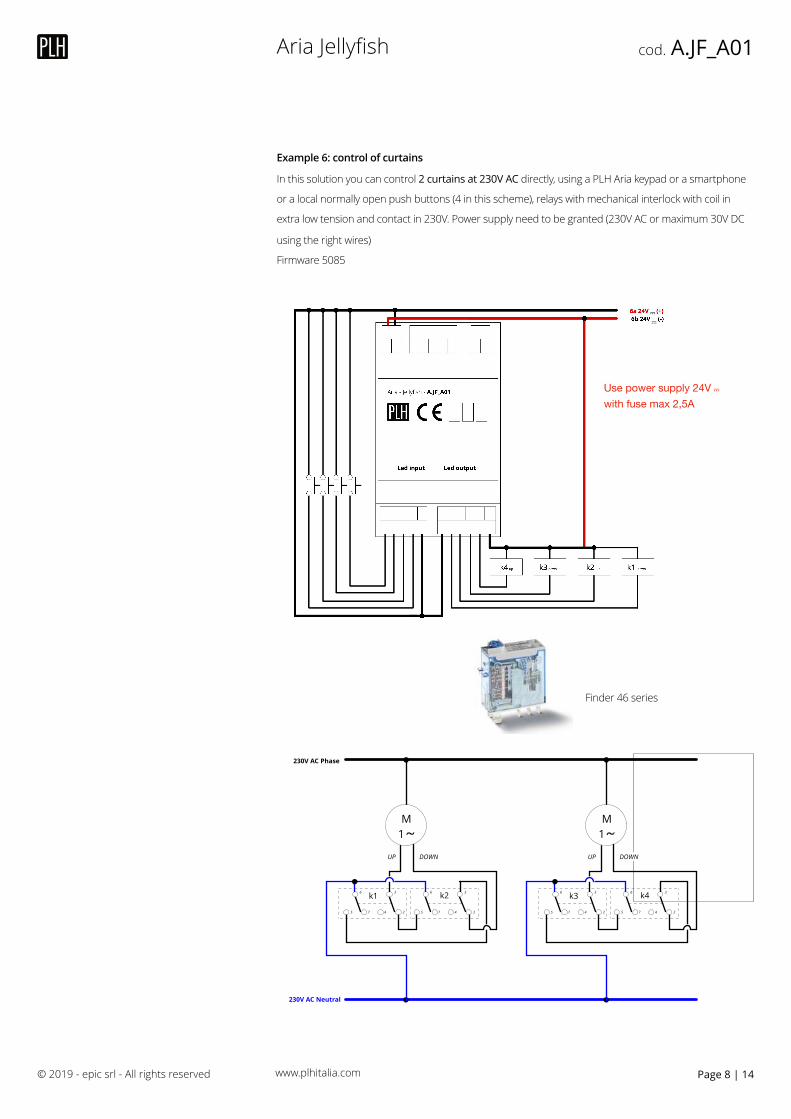
Example 6: control of curtains
In this solution you can control 2 curtains at 230V AC directly, using a PLH Aria keypad or a smartphone
or a local normally open push buttons (4 in this scheme), relays with mechanical interlock with coil in
extra low tension and contact in 230V. Power supply need to be granted (230V AC or maximum 30V DC
using the right wires)
Firmware 5085
© 2019 - epic srl - All rights reserved Page | 148
Finder 46 series
k1
230V AC Phase
230V AC Neutral
M1
UP DOWN
k236 36
5 7 4 2 5 7 4 2
k3
M1
UP DOWN
k436 36
5 7 4 2 5 7 4 2
–⃨–⃨
Use power supply 24V –⃨ with fuse max 2,5A
www.plhitalia.com
Aria Jellyfish cod. A.JF_A01
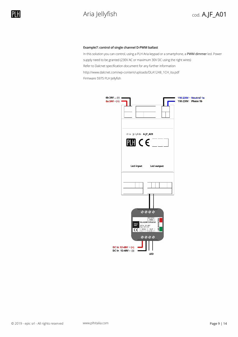
Example7: control of single channel D-PWM ballast
In this solution you can control, using a PLH Aria keypad or a smartphone, a PWM dimmer led. Power
supply need to be granted (230V AC or maximum 30V DC using the right wires)
Refer to Dalcnet specification document for any further information
http://www.dalcnet.com/wp-content/uploads/DLA1248_1CH_ita.pdf
Firmware 5975 PLH Jellyfish
© 2019 - epic srl - All rights reserved Page | 149
–⃨–⃨
–⃨–⃨
www.plhitalia.com
Aria Jellyfish cod. A.JF_A01
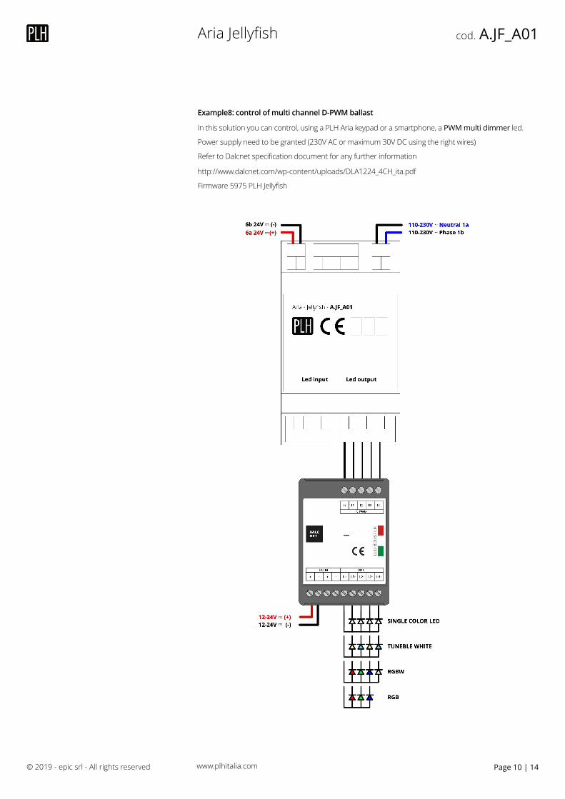
Example8: control of multi channel D-PWM ballast
In this solution you can control, using a PLH Aria keypad or a smartphone, a PWM multi dimmer led.
Power supply need to be granted (230V AC or maximum 30V DC using the right wires)
Refer to Dalcnet specification document for any further information
http://www.dalcnet.com/wp-content/uploads/DLA1224_4CH_ita.pdf
Firmware 5975 PLH Jellyfish
© 2019 - epic srl - All rights reserved Page | 1410
–⃨
–⃨–⃨
–⃨
Aria Jellyfish cod. A.JF_A01
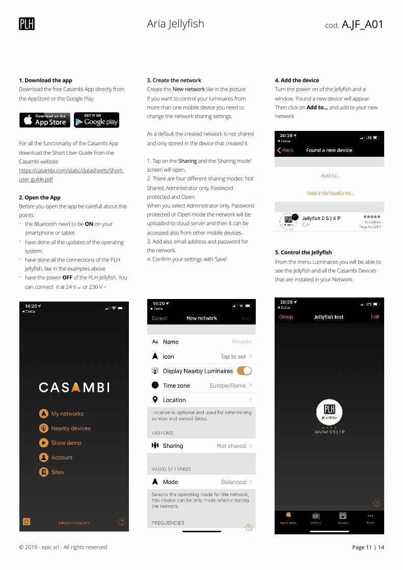
1. Download the app Download the free Casambi App directly from
the AppStore or the Google Play
� � For all the functionality of the Casambi App
download the Short User Guide from the Casambi website https://casambi.com/static/datasheets/Short-user-guide.pdf
2. Open the App Before you open the app be carefull about this points: - the Bluetooth need to be ON on your
smartphone or tablet - have done all the updates of the operating
system; - have done all the connections of the PLH
Jellyfish, like in the examples above - have the power OFF of the PLH Jellyfish. You
can connect it at 24 V –⃨ or 230 V ~
3. Create the network Create the New network like in the picture
If you want to control your luminaires from more than one mobile device you need to change the network sharing settings.
As a default the created network is not shared
and only stored in the device that created it.
1. Tap on the Sharing and the ‘Sharing mode’ screen will open. 2. There are four different sharing modes: Not
Shared, Administrator only, Password protected and Open. When you select Administrator only, Password protected or Open mode the network will be uploaded to cloud server and then it can be
accessed also from other mobile devices. 3. Add also email address and password for the network. 4. Confirm your settings with ‘Save’.
4. Add the device Turn the power on of the Jellyfish and a
window ‘Found a new device’ will appear. Then click on Add to… and add to your new network
5. Control the Jellyfish
From the menu Luminaires you will be able to see the Jellyfish and all the Casambi Devices that are installed in your Network.
© 2019 - epic srl - All rights reserved Page | 1411
Aria Jellyfish cod. A.JF_A01
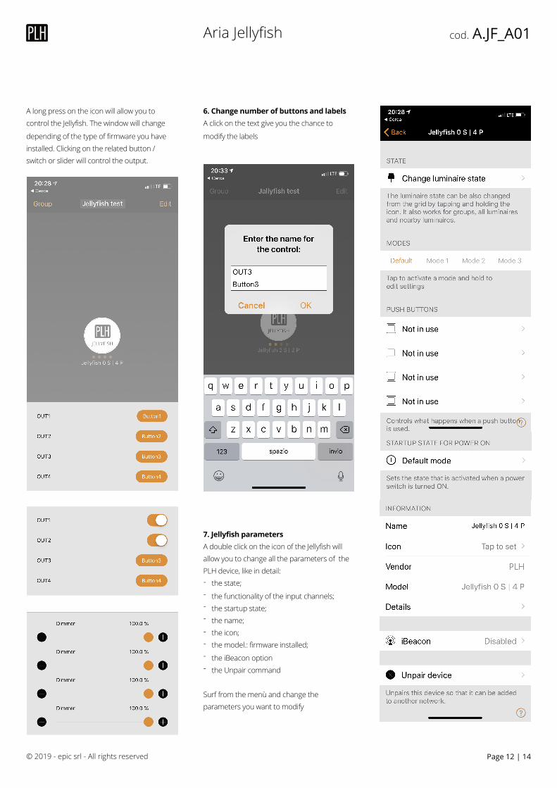
A long press on the icon will allow you to control the Jellyfish. The window will change
depending of the type of firmware you have installed. Clicking on the related button / switch or slider will control the output.
6. Change number of buttons and labels A click on the text give you the chance to
modify the labels
7. Jellyfish parameters A double click on the icon of the Jellyfish will allow you to change all the parameters of the PLH device, like in detail: - the state; - the functionality of the input channels; - the startup state; - the name; - the icon; - the model.: firmware installed; - the iBeacon option - the Unpair command
Surf from the menù and change the parameters you want to modify
© 2019 - epic srl - All rights reserved Page | 1412
Aria Jellyfish cod. A.JF_A01
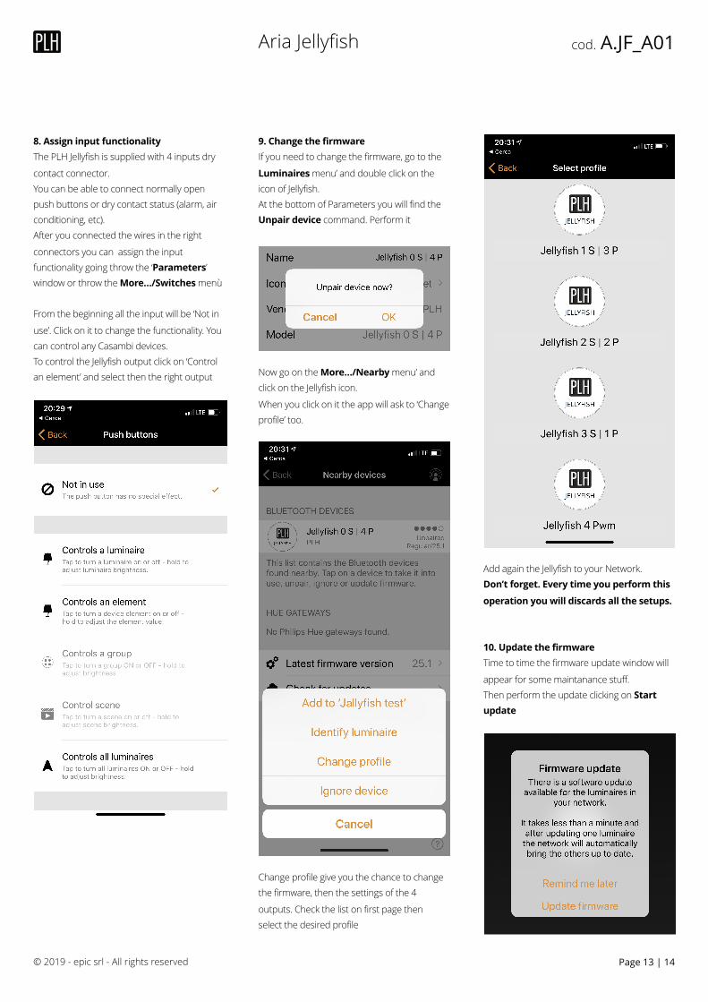
8. Assign input functionality The PLH Jellyfish is supplied with 4 inputs dry
contact connector. You can be able to connect normally open push buttons or dry contact status (alarm, air conditioning, etc). After you connected the wires in the right
connectors you can assign the input functionality going throw the ‘Parameters’ window or throw the More…/Switches menù
From the beginning all the input will be ‘Not in
use’. Click on it to change the functionality. You can control any Casambi devices. To control the Jellyfish output click on ‘Control an element’ and select then the right output
9. Change the firmware If you need to change the firmware, go to the
Luminaires menu’ and double click on the icon of Jellyfish. At the bottom of Parameters you will find the Unpair device command. Perform it
Now go on the More…/Nearby menu’ and click on the Jellyfish icon.
When you click on it the app will ask to ‘Change profile’ too.
Change profile give you the chance to change the firmware, then the settings of the 4
outputs. Check the list on first page then select the desired profile
Add again the Jellyfish to your Network. Don’t forget. Every time you perform this
operation you will discards all the setups.
10. Update the firmware Time to time the firmware update window will
appear for some maintanance stuff. Then perform the update clicking on Start update
© 2019 - epic srl - All rights reserved Page | 1413
Aria Jellyfish cod. A.JF_A01
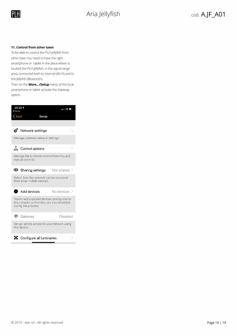
11. Control from other town To be able to control the PLH Jellyfish from
other town You need to have the right smartphone or tablet in the place where is located the PLH Jellyfish, in the signal range area, connected both to Internet (Wi-Fi) and to the Jellyfish (Bluetooth).
Then on the More…/Setup menù of the local smartphone or tablet activate the Gateway option.
© 2019 - epic srl - All rights reserved Page | 1414

![Finding a Dense-Core in Jellyfish Graphsyash/48630029.pdf · Finding a Dense-Core in Jellyfish Graphs 31 Subramanian et al. [32] suggested a 5-tier hierarchical layering of the](https://img.pdfslide.us/doc/110x75/5edad3eb09ac2c67fa685ec6/finding-a-dense-core-in-jellyish-yash48630029pdf-finding-a-dense-core-in-jellyish.jpg)


![Jellyfish: Networking Data Centers Randomly · 2012-03-18 · Jellyfish: Networking Data Centers Randomly Ankit Singla†, Chi-Yao Hong †, Lucian Popa], P. Brighten Godfrey†](https://img.pdfslide.us/doc/110x75/5fafd4b37763b9452937915f/jellyish-networking-data-centers-randomly-2012-03-18-jellyish-networking.jpg)