Embed Size (px)
Citation preview
Data sheet 003001 englisch (english)Edition 06/13 - Data subject to alteration - Regularly updated data on www.ari-armaturen.com!
ARI-CHECKO®-V - Straight through with flanges
TRB 801 Annex II No. 45 (except EN-JL1040)EN ISO 15848-1 / TA - Luft TÜV-Test-No. 973-10675245-10 C
•
•
Grey cast iron SG ironCast steelFig. 003/303 Page 2
ARI-CHECKO®-V - Straight through with flanges
TRB 801 Annex II No. 45EN ISO 15848-1 / TA - Luft TÜV-Test-No. 973-10675245-10 C
•• Forged steel
Fig. 003 Page 3
ARI-CHECKO®-V - Straight through with flanges
TRB 801 Annex II No. 45EN ISO 15848-1 / TA - Luft TÜV-Test-No. 973-10675245-10 C
•• Stainless steel
Fig. 003 Page 4
ARI-CHECKO®-V - Angle pattern with flanges
TRB 801 Annex II No. 45 (except EN-JL1040)EN ISO 15848-1 / TA - Luft TÜV-Test-No. 973-10675245-10 C
•
•
Grey cast iron SG ironCast steel Fig. 004/304 Page 5
ARI-CHECKO®-V - Straight through with butt weld ends
TRB 801 Annex II No. 45EN ISO 15848-1 / TA - Luft TÜV-Test-No. 973-10675245-10 C
•• Forged steel
Fig. 030 Page 6
ARI-CHECKO®-V - Straight through with butt weld ends
TRB 801 Annex II No. 45EN ISO 15848-1 / TA - Luft TÜV-Test-No. 973-10675245-10 C
•• Cast steel
Fig. 030 Page 7
ARI-CHECKO®-V - Y-pattern with flanges
TRB 801 Annex II No. 45EN ISO 15848-1 / TA - Luft TÜV-Test-No. 973-10675245-10 C
•• Stainless steel
Fig. 039 Page 8
ARI-CHECKO®-V - Y-pattern with butt weld ends
TRB 801 Annex II No. 45EN ISO 15848-1 / TA - Luft TÜV-Test-No. 973-10675245-10 C
•• Cast steel
Fig. 063 Page 9
ARI-CHECKO®-D - Disc check valve in clamping version
TRB 801 Annex II No. 45 • Stainless steelFig. 001 Page 10
ARI-CHECKO®-V / -DCheck valve
ARI-Check valve, metallic sealing
Features: Solid plug / valve plate made of stainless materialSolid seat made of stainless materialRe-setting spring made of stainless steelPrecise plug / valve plate guidance
••••
Fig. 003
Fig. 001
2 Edition 06/13 - Data subject to alteration - Regularly updated data on www.ari-armaturen.com!
ARI-CHECKO®-V 003 / 303Technical data
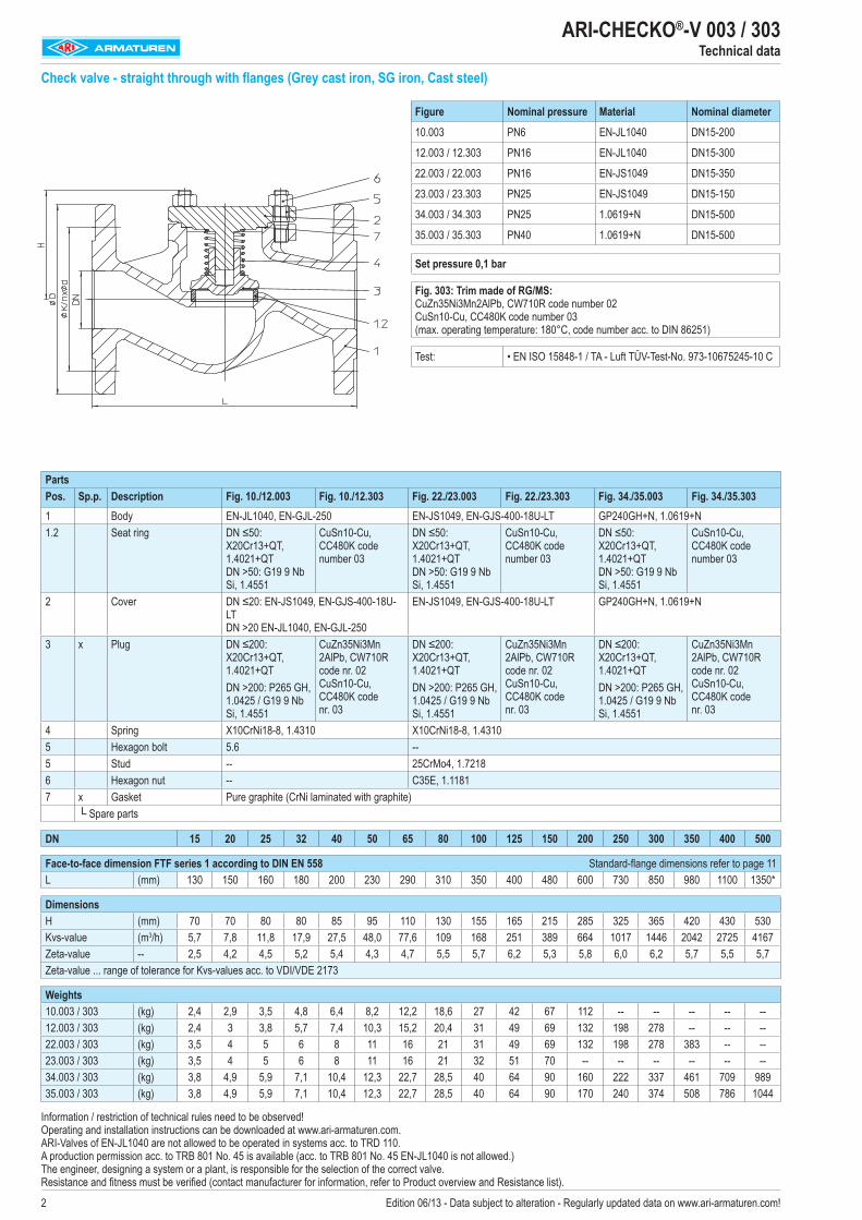
Check valve - straight through with flanges (Grey cast iron, SG iron, Cast steel)
PartsPos. Sp.p. Description Fig. 10./12.003 Fig. 10./12.303 Fig. 22./23.003 Fig. 22./23.303 Fig. 34./35.003 Fig. 34./35.3031 Body EN-JL1040, EN-GJL-250 EN-JS1049, EN-GJS-400-18U-LT GP240GH+N, 1.0619+N1.2 Seat ring DN ≤50:
X20Cr13+QT, 1.4021+QT DN >50: G19 9 Nb Si, 1.4551
CuSn10-Cu, CC480K code number 03
DN ≤50: X20Cr13+QT, 1.4021+QT DN >50: G19 9 Nb Si, 1.4551
CuSn10-Cu, CC480K code number 03
DN ≤50: X20Cr13+QT, 1.4021+QT DN >50: G19 9 Nb Si, 1.4551
CuSn10-Cu, CC480K code number 03
2 Cover DN ≤20: EN-JS1049, EN-GJS-400-18U-LT DN >20 EN-JL1040, EN-GJL-250
EN-JS1049, EN-GJS-400-18U-LT GP240GH+N, 1.0619+N
3 x Plug DN ≤200: X20Cr13+QT, 1.4021+QT DN >200: P265 GH, 1.0425 / G19 9 Nb Si, 1.4551
CuZn35Ni3Mn 2AlPb, CW710R code nr. 02 CuSn10-Cu, CC480K code nr. 03
DN ≤200: X20Cr13+QT, 1.4021+QT DN >200: P265 GH, 1.0425 / G19 9 Nb Si, 1.4551
CuZn35Ni3Mn 2AlPb, CW710R code nr. 02 CuSn10-Cu, CC480K code nr. 03
DN ≤200: X20Cr13+QT, 1.4021+QT DN >200: P265 GH, 1.0425 / G19 9 Nb Si, 1.4551
CuZn35Ni3Mn 2AlPb, CW710R code nr. 02 CuSn10-Cu, CC480K code nr. 03
4 Spring X10CrNi18-8, 1.4310 X10CrNi18-8, 1.43105 Hexagon bolt 5.6 --5 Stud -- 25CrMo4, 1.72186 Hexagon nut -- C35E, 1.11817 x Gasket Pure graphite (CrNi laminated with graphite)
└ Spare parts
DN 15 20 25 32 40 50 65 80 100 125 150 200 250 300 350 400 500
Face-to-face dimension FTF series 1 according to DIN EN 558 Standard-flange dimensions refer to page 11L (mm) 130 150 160 180 200 230 290 310 350 400 480 600 730 850 980 1100 1350*
DimensionsH (mm) 70 70 80 80 85 95 110 130 155 165 215 285 325 365 420 430 530Kvs-value (m3/h) 5,7 7,8 11,8 17,9 27,5 48,0 77,6 109 168 251 389 664 1017 1446 2042 2725 4167Zeta-value -- 2,5 4,2 4,5 5,2 5,4 4,3 4,7 5,5 5,7 6,2 5,3 5,8 6,0 6,2 5,7 5,5 5,7Zeta-value ... range of tolerance for Kvs-values acc. to VDI/VDE 2173
Weights10.003 / 303 (kg) 2,4 2,9 3,5 4,8 6,4 8,2 12,2 18,6 27 42 67 112 -- -- -- -- --12.003 / 303 (kg) 2,4 3 3,8 5,7 7,4 10,3 15,2 20,4 31 49 69 132 198 278 -- -- --22.003 / 303 (kg) 3,5 4 5 6 8 11 16 21 31 49 69 132 198 278 383 -- --23.003 / 303 (kg) 3,5 4 5 6 8 11 16 21 32 51 70 -- -- -- -- -- --34.003 / 303 (kg) 3,8 4,9 5,9 7,1 10,4 12,3 22,7 28,5 40 64 90 160 222 337 461 709 98935.003 / 303 (kg) 3,8 4,9 5,9 7,1 10,4 12,3 22,7 28,5 40 64 90 170 240 374 508 786 1044
Figure Nominal pressure Material Nominal diameter
10.003 PN6 EN-JL1040 DN15-200
12.003 / 12.303 PN16 EN-JL1040 DN15-300
22.003 / 22.003 PN16 EN-JS1049 DN15-350
23.003 / 23.303 PN25 EN-JS1049 DN15-150
34.003 / 34.303 PN25 1.0619+N DN15-500
35.003 / 35.303 PN40 1.0619+N DN15-500
Set pressure 0,1 bar
Fig. 303: Trim made of RG/MS: CuZn35Ni3Mn2AlPb, CW710R code number 02 CuSn10-Cu, CC480K code number 03 (max. operating temperature: 180°C, code number acc. to DIN 86251)
Test: • EN ISO 15848-1 / TA - Luft TÜV-Test-No. 973-10675245-10 C
Information / restriction of technical rules need to be observed! Operating and installation instructions can be downloaded at www.ari-armaturen.com. ARI-Valves of EN-JL1040 are not allowed to be operated in systems acc. to TRD 110. A production permission acc. to TRB 801 No. 45 is available (acc. to TRB 801 No. 45 EN-JL1040 is not allowed.) The engineer, designing a system or a plant, is responsible for the selection of the correct valve. Resistance and fitness must be verified (contact manufacturer for information, refer to Product overview and Resistance list).
3Edition 06/13 - Data subject to alteration - Regularly updated data on www.ari-armaturen.com!
ARI-CHECKO®-V 003Technical data
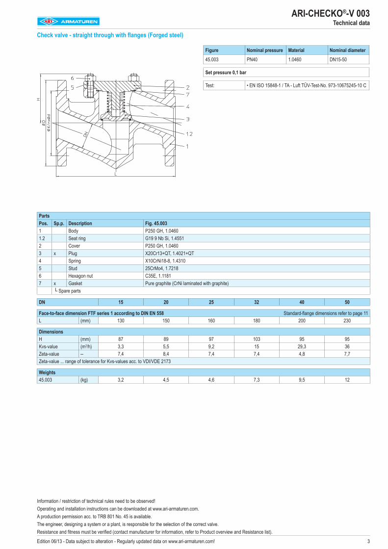
Check valve - straight through with flanges (Forged steel)
Figure Nominal pressure Material Nominal diameter
45.003 PN40 1.0460 DN15-50
Set pressure 0,1 bar
Test: • EN ISO 15848-1 / TA - Luft TÜV-Test-No. 973-10675245-10 C
PartsPos. Sp.p. Description Fig. 45.0031 Body P250 GH, 1.04601.2 Seat ring G19 9 Nb Si, 1.45512 Cover P250 GH, 1.04603 x Plug X20Cr13+QT, 1.4021+QT 4 Spring X10CrNi18-8, 1.43105 Stud 25CrMo4, 1.72186 Hexagon nut C35E, 1.11817 x Gasket Pure graphite (CrNi laminated with graphite)
└ Spare parts
DN 15 20 25 32 40 50
Face-to-face dimension FTF series 1 according to DIN EN 558 Standard-flange dimensions refer to page 11L (mm) 130 150 160 180 200 230
DimensionsH (mm) 87 89 97 103 95 95Kvs-value (m3/h) 3,3 5,5 9,2 15 29,3 36Zeta-value -- 7,4 8,4 7,4 7,4 4,8 7,7Zeta-value ... range of tolerance for Kvs-values acc. to VDI/VDE 2173
Weights45.003 (kg) 3,2 4,5 4,6 7,3 9,5 12
Information / restriction of technical rules need to be observed!Operating and installation instructions can be downloaded at www.ari-armaturen.com. A production permission acc. to TRB 801 No. 45 is available. The engineer, designing a system or a plant, is responsible for the selection of the correct valve. Resistance and fitness must be verified (contact manufacturer for information, refer to Product overview and Resistance list).
4 Edition 06/13 - Data subject to alteration - Regularly updated data on www.ari-armaturen.com!
ARI-CHECKO®-V 003Technical data
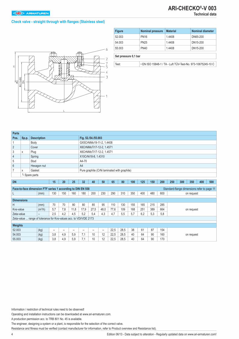
Check valve - straight through with flanges (Stainless steel)
Figure Nominal pressure Material Nominal diameter
52.003 PN16 1.4408 DN65-200
54.003 PN25 1.4408 DN15-200
55.003 PN40 1.4408 DN15-200
Set pressure 0,1 bar
Test: • EN ISO 15848-1 / TA - Luft TÜV-Test-No. 973-10675245-10 C
PartsPos. Sp.p. Description Fig. 52./54./55.0031 Body GX5CrNiMo19-11-2, 1.44082 Cover X6CrNiMoTi17-12-2, 1.45713 x Plug X6CrNiMoTi17-12-2, 1.45714 Spring X10CrNi18-8, 1.43105 Stud A4-706 Hexagon nut A47 x Gasket Pure graphite (CrNi laminated with graphite)
└ Spare parts
DN 15 20 25 32 40 50 65 80 100 125 150 200 250 300 350 400 500
Face-to-face dimension FTF series 1 according to DIN EN 558 Standard-flange dimensions refer to page 11L (mm) 130 150 160 180 200 230 290 310 350 400 480 600 on request
DimensionsH (mm) 70 70 80 80 85 95 110 130 155 165 215 285
on requestKvs-value (m3/h) 5,7 7,8 11,8 17,9 27,5 48,0 77,6 109 168 251 389 664Zeta-value -- 2,5 4,2 4,5 5,2 5,4 4,3 4,7 5,5 5,7 6,2 5,3 5,8Zeta-value ... range of tolerance for Kvs-values acc. to VDI/VDE 2173
Weights52.003 (kg) -- -- -- -- -- -- 22,5 28,5 38 61 87 154
on request54.003 (kg) 3,8 4,9 5,9 7,1 10 12 22,5 28,5 40 64 90 16055.003 (kg) 3,8 4,9 5,9 7,1 10 12 22,5 28,5 40 64 90 170
Information / restriction of technical rules need to be observed!Operating and installation instructions can be downloaded at www.ari-armaturen.com. A production permission acc. to TRB 801 No. 45 is available. The engineer, designing a system or a plant, is responsible for the selection of the correct valve. Resistance and fitness must be verified (contact manufacturer for information, refer to Product overview and Resistance list).
�Edition 06/13 - Data subject to alteration - Regularly updated data on www.ari-armaturen.com!
ARI-CHECKO®-V 004 / 304Technical data
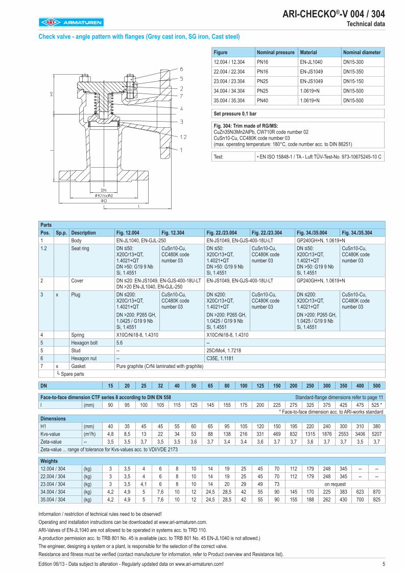
Check valve - angle pattern with flanges (Grey cast iron, SG iron, Cast steel)
PartsPos. Sp.p. Description Fig. 12.004 Fig. 12.304 Fig. 22./23.004 Fig. 22./23.304 Fig. 34./35.004 Fig. 34./35.3041 Body EN-JL1040, EN-GJL-2�0 EN-JS1049, EN-GJS-400-18U-LT GP240GH+N, 1.0619+N1.2 Seat ring DN ≤50:
X20Cr13+QT, 1.4021+QT DN >50: G19 9 Nb Si, 1.4��1
CuSn10-Cu, CC480K code number 03
DN ≤50: X20Cr13+QT, 1.4021+QT DN >50: G19 9 Nb Si, 1.4��1
CuSn10-Cu, CC480K code number 03
DN ≤50: X20Cr13+QT, 1.4021+QT DN >50: G19 9 Nb Si, 1.4��1
CuSn10-Cu, CC480K code number 03
2 Cover DN ≤20: EN-JS1049, EN-GJS-400-18U-LT DN >20 EN-JL1040, EN-GJL-2�0
EN-JS1049, EN-GJS-400-18U-LT GP240GH+N, 1.0619+N
3 x Plug DN ≤200: X20Cr13+QT, 1.4021+QT DN >200: P265 GH, 1.042� / G19 9 Nb Si, 1.4��1
CuSn10-Cu, CC480K code number 03
DN ≤200: X20Cr13+QT, 1.4021+QT DN >200: P265 GH, 1.042� / G19 9 Nb Si, 1.4��1
CuSn10-Cu, CC480K code number 03
DN ≤200: X20Cr13+QT, 1.4021+QT DN >200: P265 GH, 1.042� / G19 9 Nb Si, 1.4��1
CuSn10-Cu, CC480K code number 03
4 Spring X10CrNi18-8, 1.4310 X10CrNi18-8, 1.4310� Hexagon bolt �.6 --� Stud -- 2�CrMo4, 1.72186 Hexagon nut -- C3�E, 1.11817 x Gasket Pure graphite (CrNi laminated with graphite)
└ Spare parts
DN 15 20 25 32 40 50 65 80 100 125 150 200 250 300 350 400 500
Face-to-face dimension CTF series 8 according to DIN EN 558 Standard-flange dimensions refer to page 11l (mm) 90 9� 100 10� 11� 12� 14� 1�� 17� 200 22� 27� 32� 37� 42� 47� �2� * * Face-to-face dimension acc. to ARI-works standardDimensionsH1 (mm) 40 3� 4� 4� �� 60 6� 9� 10� 120 1�0 19� 220 240 300 310 380Kvs-value (m3/h) 4,8 8,� 13 22 34 �3 88 138 216 331 469 832 131� 1876 2��3 3406 �207Zeta-value -- 3,� 3,� 3,7 3,� 3,� 3,6 3,7 3,4 3,4 3,6 3,7 3,7 3,6 3,7 3,7 3,� 3,7Zeta-value ... range of tolerance for Kvs-values acc. to VDI/VDE 2173
Weights12.004 / 304 (kg) 3 3,� 4 6 8 10 14 19 2� 4� 70 112 179 248 34� -- --22.004 / 304 (kg) 3 3,� 4 6 8 10 14 19 2� 4� 70 112 179 248 34� -- --23.004 / 304 (kg) 3 3,� 4,1 6 8 10 14 20 29 49 73 on request34.004 / 304 (kg) 4,2 4,9 � 7,6 10 12 24,� 28,� 42 �� 90 14� 170 22� 383 623 8703�.004 / 304 (kg) 4,2 4,9 � 7,6 10 12 24,� 28,� 42 �� 90 1�� 188 262 430 700 92�
Figure Nominal pressure Material Nominal diameter
12.004 / 12.304 PN16 EN-JL1040 DN1�-300
22.004 / 22.304 PN16 EN-JS1049 DN1�-3�0
23.004 / 23.304 PN2� EN-JS1049 DN1�-1�0
34.004 / 34.304 PN2� 1.0619+N DN1�-�00
3�.004 / 3�.304 PN40 1.0619+N DN1�-�00
Set pressure 0,1 bar
Fig. 304: Trim made of RG/MS: CuZn3�Ni3Mn2AlPb, CW710R code number 02 CuSn10-Cu, CC480K code number 03 (max. operating temperature: 180°C, code number acc. to DIN 86251)
Test: • EN ISO 1�848-1 / TA - Luft TÜV-Test-No. 973-1067�24�-10 C
Information / restriction of technical rules need to be observed!Operating and installation instructions can be downloaded at www.ari-armaturen.com. ARI-Valves of EN-JL1040 are not allowed to be operated in systems acc. to TRD 110.A production permission acc. to TRB 801 No. 4� is available (acc. to TRB 801 No. 4� EN-JL1040 is not allowed.)The engineer, designing a system or a plant, is responsible for the selection of the correct valve. Resistance and fitness must be verified (contact manufacturer for information, refer to Product overview and Resistance list).
6 Edition 06/13 - Data subject to alteration - Regularly updated data on www.ari-armaturen.com!
ARI-CHECKO®-V 030Technical data
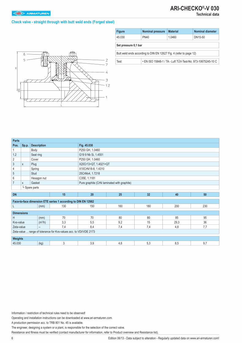
Check valve - straight through with butt weld ends (Forged steel)
Figure Nominal pressure Material Nominal diameter
45.030 PN40 1.0460 DN15-50
Set pressure 0,1 bar
Butt weld ends according to DIN EN 12627 Fig. 4 (refer to page 12)
Test: • EN ISO 15848-1 / TA - Luft TÜV-Test-No. 973-10675245-10 C
PartsPos. Sp.p. Description Fig. 45.0301 Body P250 GH, 1.04601.2 Seat ring G19 9 Nb Si, 1.45512 Cover P250 GH, 1.04603 x Plug X20Cr13+QT, 1.4021+QT 4 Spring X10CrNi18-8, 1.43105 Stud 25CrMo4, 1.72186 Hexagon nut C35E, 1.11817 x Gasket Pure graphite (CrNi laminated with graphite)
└ Spare parts
DN 15 20 25 32 40 50
Face-to-face dimension ETE series 1 according to DIN EN 12982L (mm) 130 150 160 180 200 230
DimensionsH (mm) 70 70 80 80 85 95Kvs-value (m3/h) 3,3 5,5 9,2 15 29,3 36Zeta-value -- 7,4 8,4 7,4 7,4 4,8 7,7Zeta-value ... range of tolerance for Kvs-values acc. to VDI/VDE 2173
Weights45.030 (kg) 3 3,9 4,6 5,3 8,5 9,7
Information / restriction of technical rules need to be observed!Operating and installation instructions can be downloaded at www.ari-armaturen.com. A production permission acc. to TRB 801 No. 45 is available. The engineer, designing a system or a plant, is responsible for the selection of the correct valve. Resistance and fitness must be verified (contact manufacturer for information, refer to Product overview and Resistance list).
7Edition 06/13 - Data subject to alteration - Regularly updated data on www.ari-armaturen.com!
ARI-CHECKO®-V 030Technical data
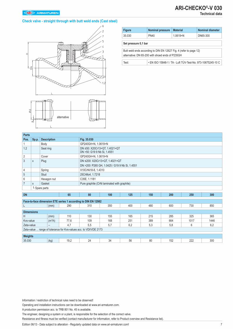
Check valve - straight through with butt weld ends (Cast steel)
Figure Nominal pressure Material Nominal diameter
35.030 PN40 1.0619+N DN65-300
Set pressure 0,1 bar
Butt weld ends according to DIN EN 12627 Fig. 4 (refer to page 12) alternative: DN 65-200 with shoed ends of P235GH
Test: • EN ISO 15848-1 / TA - Luft TÜV-Test-No. 973-10675245-10 C
PartsPos. Sp.p. Description Fig. 35.0301 Body GP240GH+N, 1.0619+N1.2 Seat ring DN ≤50: X20Cr13+QT, 1.4021+QT
DN >50: G19 9 Nb Si, 1.45512 Cover GP240GH+N, 1.0619+N3 x Plug DN ≤200: X20Cr13+QT, 1.4021+QT
DN >200: P265 GH, 1.0425 / G19 9 Nb Si, 1.45514 Spring X10CrNi18-8, 1.43105 Stud 25CrMo4, 1.72186 Hexagon nut C35E, 1.11817 x Gasket Pure graphite (CrNi laminated with graphite)
└ Spare parts
DN 65 80 100 125 150 200 250 300
Face-to-face dimension ETE series 1 according to DIN EN 12982L (mm) 290 310 350 400 480 600 730 850
DimensionsH (mm) 110 130 155 165 215 285 325 365Kvs-value (m3/h) 77,6 109 168 251 389 664 1017 1446Zeta-value -- 4,7 5,5 5,7 6,2 5,3 5,8 6 6,2Zeta-value ... range of tolerance for Kvs-values acc. to VDI/VDE 2173
Weights35.030 (kg) 19,2 24 34 56 80 152 222 300
alternative
Information / restriction of technical rules need to be observed!Operating and installation instructions can be downloaded at www.ari-armaturen.com. A production permission acc. to TRB 801 No. 45 is available.The engineer, designing a system or a plant, is responsible for the selection of the correct valve. Resistance and fitness must be verified (contact manufacturer for information, refer to Product overview and Resistance list).
8 Edition 06/13 - Data subject to alteration - Regularly updated data on www.ari-armaturen.com!
ARI-CHECKO®-V 039Technical data
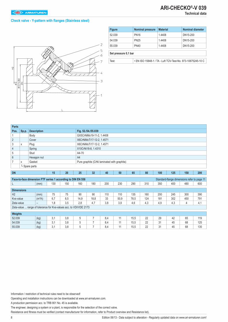
Check valve - Y-pattern with flanges (Stainless steel)
Figure Nominal pressure Material Nominal diameter
52.039 PN16 1.4408 DN15-200
54.039 PN25 1.4408 DN15-200
55.039 PN40 1.4408 DN15-200
Set pressure 0,1 bar
Test: • EN ISO 15848-1 / TA - Luft TÜV-Test-No. 973-10675245-10 C
PartsPos. Sp.p. Description Fig. 52./54./55.0391 Body GX5CrNiMo19-11-2, 1.44082 Cover X6CrNiMoTi17-12-2, 1.45713 x Plug X6CrNiMoTi17-12-2, 1.45714 Spring X10CrNi18-8, 1.43105 Stud A4-706 Hexagon nut A47 x Gasket Pure graphite (CrNi laminated with graphite)
└ Spare parts
DN 15 20 25 32 40 50 65 80 100 125 150 200
Face-to-face dimension FTF series 1 according to DIN EN 558 Standard-flange dimensions refer to page 11L (mm) 130 150 160 180 200 230 290 310 350 400 480 600
DimensionsH2 (mm) 75 75 90 90 110 110 135 160 200 245 300 390Kvs-value (m3/h) 6,7 8,5 14,9 18,8 33 50,9 78,5 124 181 302 450 791Zeta-value -- 1,8 3,5 2,8 4,7 3,8 3,9 4,6 4,3 4,9 4,3 4 4,1Zeta-value ... range of tolerance for Kvs-values acc. to VDI/VDE 2173
Weights52.039 (kg) 3,1 3,8 5 7 8,4 11 15,5 22 29 42 65 11954.039 (kg) 3,1 3,8 5 7 8,4 11 15,5 22 31 45 68 12555.039 (kg) 3,1 3,8 5 7 8,4 11 15,5 22 31 45 68 135
Information / restriction of technical rules need to be observed!Operating and installation instructions can be downloaded at www.ari-armaturen.com. A production permission acc. to TRB 801 No. 45 is available. The engineer, designing a system or a plant, is responsible for the selection of the correct valve. Resistance and fitness must be verified (contact manufacturer for information, refer to Product overview and Resistance list).
9Edition 06/13 - Data subject to alteration - Regularly updated data on www.ari-armaturen.com!
ARI-CHECKO®-V 063Technical data
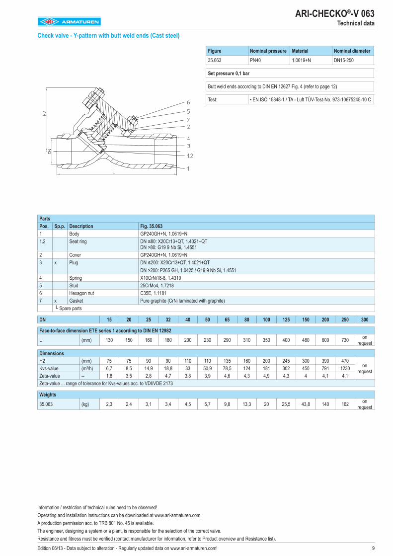
Check valve - Y-pattern with butt weld ends (Cast steel)
Figure Nominal pressure Material Nominal diameter
35.063 PN40 1.0619+N DN15-250
Set pressure 0,1 bar
Butt weld ends according to DIN EN 12627 Fig. 4 (refer to page 12)
Test: • EN ISO 15848-1 / TA - Luft TÜV-Test-No. 973-10675245-10 C
PartsPos. Sp.p. Description Fig. 35.0631 Body GP240GH+N, 1.0619+N1.2 Seat ring DN ≤80: X20Cr13+QT, 1.4021+QT
DN >80: G19 9 Nb Si, 1.45512 Cover GP240GH+N, 1.0619+N3 x Plug DN ≤200: X20Cr13+QT, 1.4021+QT
DN >200: P265 GH, 1.0425 / G19 9 Nb Si, 1.45514 Spring X10CrNi18-8, 1.43105 Stud 25CrMo4, 1.72186 Hexagon nut C35E, 1.11817 x Gasket Pure graphite (CrNi laminated with graphite)
└ Spare parts
DN 15 20 25 32 40 50 65 80 100 125 150 200 250 300
Face-to-face dimension ETE series 1 according to DIN EN 12982
L (mm) 130 150 160 180 200 230 290 310 350 400 480 600 730 on request
DimensionsH2 (mm) 75 75 90 90 110 110 135 160 200 245 300 390 470
on requestKvs-value (m3/h) 6,7 8,5 14,9 18,8 33 50,9 78,5 124 181 302 450 791 1230
Zeta-value -- 1,8 3,5 2,8 4,7 3,8 3,9 4,6 4,3 4,9 4,3 4 4,1 4,1Zeta-value ... range of tolerance for Kvs-values acc. to VDI/VDE 2173
Weights
35.063 (kg) 2,3 2,4 3,1 3,4 4,5 5,7 9,8 13,3 20 25,5 43,8 140 162 on request
Information / restriction of technical rules need to be observed!Operating and installation instructions can be downloaded at www.ari-armaturen.com. A production permission acc. to TRB 801 No. 45 is available.The engineer, designing a system or a plant, is responsible for the selection of the correct valve. Resistance and fitness must be verified (contact manufacturer for information, refer to Product overview and Resistance list).
10 Edition 06/13 - Data subject to alteration - Regularly updated data on www.ari-armaturen.com!
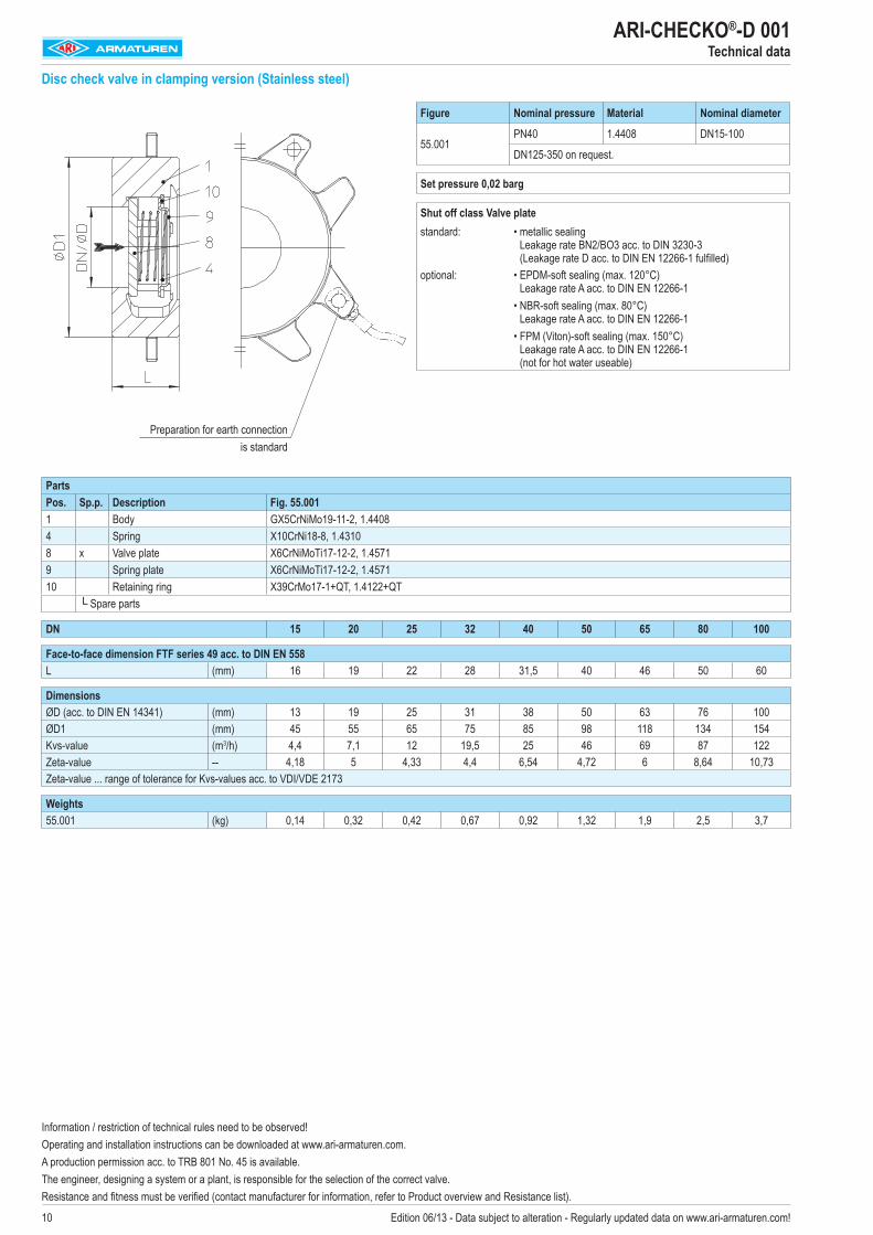
ARI-CHECKO®-D 001Technical data
Disc check valve in clamping version (Stainless steel)
Figure Nominal pressure Material Nominal diameter
55.001PN40 1.4408 DN15-100
DN125-350 on request.
Set pressure 0,02 barg
Shut off class Valve platestandard: • metallic sealing
Leakage rate BN2/BO3 acc. to DIN 3230-3 (Leakage rate D acc. to DIN EN 12266-1 fulfilled)
optional: • EPDM-soft sealing (max. 120°C) Leakage rate A acc. to DIN EN 12266-1
• NBR-soft sealing (max. 80°C) Leakage rate A acc. to DIN EN 12266-1
• FPM (Viton)-soft sealing (max. 150°C) Leakage rate A acc. to DIN EN 12266-1 (not for hot water useable)
PartsPos. Sp.p. Description Fig. 55.0011 Body GX5CrNiMo19-11-2, 1.44084 Spring X10CrNi18-8, 1.43108 x Valve plate X6CrNiMoTi17-12-2, 1.45719 Spring plate X6CrNiMoTi17-12-2, 1.457110 Retaining ring X39CrMo17-1+QT, 1.4122+QT
└ Spare parts
DN 15 20 25 32 40 50 65 80 100
Face-to-face dimension FTF series 49 acc. to DIN EN 558L (mm) 16 19 22 28 31,5 40 46 50 60
DimensionsØD (acc. to DIN EN 14341) (mm) 13 19 25 31 38 50 63 76 100ØD1 (mm) 45 55 65 75 85 98 118 134 154Kvs-value (m3/h) 4,4 7,1 12 19,5 25 46 69 87 122Zeta-value -- 4,18 5 4,33 4,4 6,54 4,72 6 8,64 10,73Zeta-value ... range of tolerance for Kvs-values acc. to VDI/VDE 2173
Weights55.001 (kg) 0,14 0,32 0,42 0,67 0,92 1,32 1,9 2,5 3,7
Preparation for earth connection is standard
Information / restriction of technical rules need to be observed!Operating and installation instructions can be downloaded at www.ari-armaturen.com. A production permission acc. to TRB 801 No. 45 is available. The engineer, designing a system or a plant, is responsible for the selection of the correct valve. Resistance and fitness must be verified (contact manufacturer for information, refer to Product overview and Resistance list).
11Edition 06/13 - Data subject to alteration - Regularly updated data on www.ari-armaturen.com!
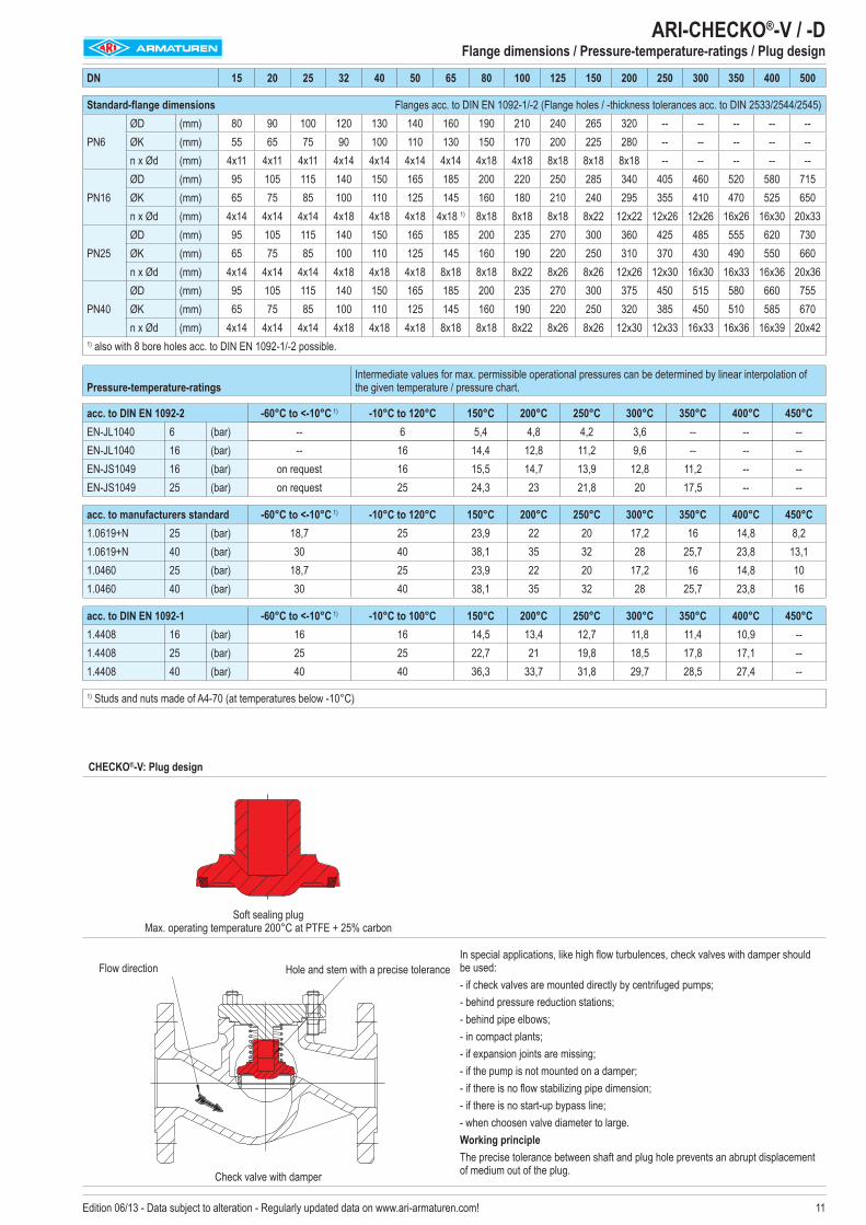
DN 15 20 25 32 40 50 65 80 100 125 150 200 250 300 350 400 500
Standard-flange dimensions Flanges acc. to DIN EN 1092-1/-2 (Flange holes / -thickness tolerances acc. to DIN 2533/2544/2545)
PN6ØD (mm) 80 90 100 120 130 140 160 190 210 240 265 320 -- -- -- -- --ØK (mm) 55 65 75 90 100 110 130 150 170 200 225 280 -- -- -- -- --n x Ød (mm) 4x11 4x11 4x11 4x14 4x14 4x14 4x14 4x18 4x18 8x18 8x18 8x18 -- -- -- -- --
PN16ØD (mm) 95 105 115 140 150 165 185 200 220 250 285 340 405 460 520 580 715ØK (mm) 65 75 85 100 110 125 145 160 180 210 240 295 355 410 470 525 650n x Ød (mm) 4x14 4x14 4x14 4x18 4x18 4x18 4x18 1) 8x18 8x18 8x18 8x22 12x22 12x26 12x26 16x26 16x30 20x33
PN25ØD (mm) 95 105 115 140 150 165 185 200 235 270 300 360 425 485 555 620 730ØK (mm) 65 75 85 100 110 125 145 160 190 220 250 310 370 430 490 550 660n x Ød (mm) 4x14 4x14 4x14 4x18 4x18 4x18 8x18 8x18 8x22 8x26 8x26 12x26 12x30 16x30 16x33 16x36 20x36
PN40ØD (mm) 95 105 115 140 150 165 185 200 235 270 300 375 450 515 580 660 755ØK (mm) 65 75 85 100 110 125 145 160 190 220 250 320 385 450 510 585 670n x Ød (mm) 4x14 4x14 4x14 4x18 4x18 4x18 8x18 8x18 8x22 8x26 8x26 12x30 12x33 16x33 16x36 16x39 20x42
1) also with 8 bore holes acc. to DIN EN 1092-1/-2 possible.
Pressure-temperature-ratings Intermediate values for max. permissible operational pressures can be determined by linear interpolation of the given temperature / pressure chart.
acc. to DIN EN 1092-2 -60°C to <-10°C 1) -10°C to 120°C 150°C 200°C 250°C 300°C 350°C 400°C 450°CEN-JL1040 6 (bar) -- 6 5,4 4,8 4,2 3,6 -- -- --EN-JL1040 16 (bar) -- 16 14,4 12,8 11,2 9,6 -- -- --EN-JS1049 16 (bar) on request 16 15,5 14,7 13,9 12,8 11,2 -- --EN-JS1049 25 (bar) on request 25 24,3 23 21,8 20 17,5 -- --
acc. to manufacturers standard -60°C to <-10°C 1) -10°C to 120°C 150°C 200°C 250°C 300°C 350°C 400°C 450°C1.0619+N 25 (bar) 18,7 25 23,9 22 20 17,2 16 14,8 8,21.0619+N 40 (bar) 30 40 38,1 35 32 28 25,7 23,8 13,11.0460 25 (bar) 18,7 25 23,9 22 20 17,2 16 14,8 101.0460 40 (bar) 30 40 38,1 35 32 28 25,7 23,8 16
acc. to DIN EN 1092-1 -60°C to <-10°C 1) -10°C to 100°C 150°C 200°C 250°C 300°C 350°C 400°C 450°C1.4408 16 (bar) 16 16 14,5 13,4 12,7 11,8 11,4 10,9 --1.4408 25 (bar) 25 25 22,7 21 19,8 18,5 17,8 17,1 --1.4408 40 (bar) 40 40 36,3 33,7 31,8 29,7 28,5 27,4 --
1) Studs and nuts made of A4-70 (at temperatures below -10°C)
ARI-CHECKO®-V / -D
Flange dimensions / Pressure-temperature-ratings / Plug design
CHECKO®-V: Plug design
Soft sealing plug Max. operating temperature 200°C at PTFE + 25% carbon
Check valve with damper
In special applications, like high flow turbulences, check valves with damper should be used:- if check valves are mounted directly by centrifuged pumps;- behind pressure reduction stations; - behind pipe elbows; - in compact plants; - if expansion joints are missing; - if the pump is not mounted on a damper; - if there is no flow stabilizing pipe dimension; - if there is no start-up bypass line; - when choosen valve diameter to large.Working principleThe precise tolerance between shaft and plug hole prevents an abrupt displacement of medium out of the plug.
Flow direction Hole and stem with a precise tolerance
12 Edition 06/13 - Data subject to alteration - Regularly updated data on www.ari-armaturen.com!
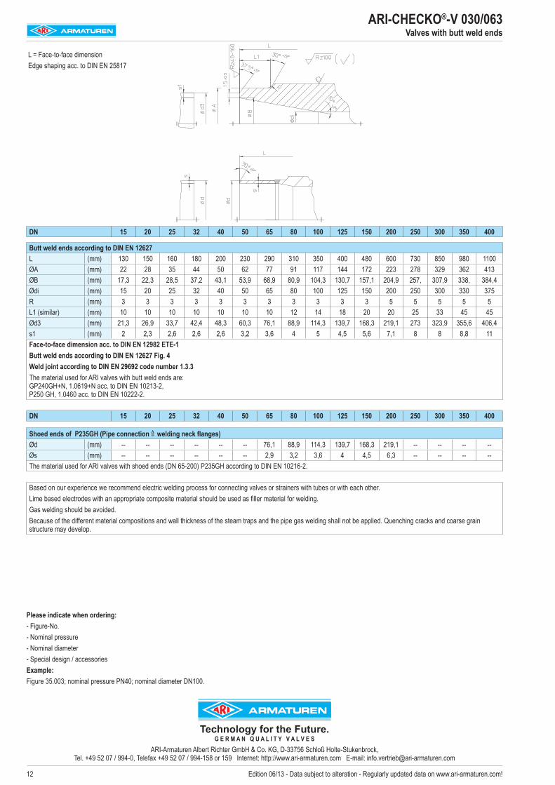
ARI-CHECKO®-V 030/063 Valves with butt weld ends
L = Face-to-face dimensionEdge shaping acc. to DIN EN 25817
Please indicate when ordering:- Figure-No. - Nominal pressure- Nominal diameter- Special design / accessoriesExample:Figure 35.003; nominal pressure PN40; nominal diameter DN100.
DN 15 20 25 32 40 50 65 80 100 125 150 200 250 300 350 400
Butt weld ends according to DIN EN 12627L (mm) 130 150 160 180 200 230 290 310 350 400 480 600 730 850 980 1100ØA (mm) 22 28 35 44 50 62 77 91 117 144 172 223 278 329 362 413ØB (mm) 17,3 22,3 28,5 37,2 43,1 53,9 68,9 80,9 104,3 130,7 157,1 204,9 257, 307,9 338, 384,4Ødi (mm) 15 20 25 32 40 50 65 80 100 125 150 200 250 300 330 375R (mm) 3 3 3 3 3 3 3 3 3 3 3 5 5 5 5 5L1 (similar) (mm) 10 10 10 10 10 10 10 12 14 18 20 20 25 33 45 45Ød3 (mm) 21,3 26,9 33,7 42,4 48,3 60,3 76,1 88,9 114,3 139,7 168,3 219,1 273 323,9 355,6 406,4s1 (mm) 2 2,3 2,6 2,6 2,6 3,2 3,6 4 5 4,5 5,6 7,1 8 8 8,8 11Face-to-face dimension acc. to DIN EN 12982 ETE-1Butt weld ends according to DIN EN 12627 Fig. 4Weld joint according to DIN EN 29692 code number 1.3.3The material used for ARI valves with butt weld ends are: GP240GH+N, 1.0619+N acc. to DIN EN 10213-2, P250 GH, 1.0460 acc. to DIN EN 10222-2.
DN 15 20 25 32 40 50 65 80 100 125 150 200 250 300 350 400
Shoed ends of P235GH (Pipe connection =̂ welding neck flanges)Ød (mm) -- -- -- -- -- -- 76,1 88,9 114,3 139,7 168,3 219,1 -- -- -- --Øs (mm) -- -- -- -- -- -- 2,9 3,2 3,6 4 4,5 6,3 -- -- -- --The material used for ARI valves with shoed ends (DN 65-200) P235GH according to DIN EN 10216-2.
Based on our experience we recommend electric welding process for connecting valves or strainers with tubes or with each other.Lime based electrodes with an appropriate composite material should be used as filler material for welding.Gas welding should be avoided.Because of the different material compositions and wall thickness of the steam traps and the pipe gas welding shall not be applied. Quenching cracks and coarse grain structure may develop.
Technology for the Future. G E R M A N Q U A L I T Y V A L V E S
ARI-Armaturen Albert Richter GmbH & Co. KG, D-33756 Schloß Holte-Stukenbrock, Tel. +49 52 07 / 994-0, Telefax +49 52 07 / 994-158 or 159 Internet: http://www.ari-armaturen.com E-mail: [email protected]