Embed Size (px)
DESCRIPTION
Manual de service
Citation preview
14.203.B_A707 en.SM.V4.3X ARGUS Medical AG 28.03.06 / PJ 1 / 48
Service Manual for Volumetric Infusion Pump
ARGUS 707 V
Made in Switzerland
ARGUS Medical AG, CH-3627 Heimberg / Switzerland (a member of the CODAN group)
14.203.B_A707 en.SM.V4.3X ARGUS Medical AG 28.03.06 / PJ 1 / 48
TABLE OF CONTENTS
1. INTRODUCTION ...........................................................................................................4 1.1. General ............................................................................................................................. 4
2. PUMP CONFIGURATIONS...........................................................................................4 2.1. General ............................................................................................................................. 4 2.2. Interrogation mode (without ARGUS service) ................................................................... 5 2.3. Configuration mode (without ARGUS service).................................................................. 6 2.4. First activation of a PIN code (write protection) ................................................................ 7 2.5. Changing an existing PIN code......................................................................................... 8 2.6. Address list of the pump configuration (without ARGUS service) ..................................... 9 2.7. Index list of the pump configuration (with ARGUS service) ............................................ 10 2.8. Special configuration options (with ARGUS service) ...................................................... 14 2.9. Medication list ................................................................................................................. 15
3. Serial communication of the pump ..........................................................................18 3.1. General ........................................................................................................................... 18 3.2. Serial communication protocol ........................................................................................ 18
4. ARGUS service...........................................................................................................19 4.1. General ........................................................................................................................... 19 4.2. ARGUS service – Configuration...................................................................................... 20 4.3. ARGUS service - Calibration (volumetric pums only) ..................................................... 21 4.4. ARGUS service - Toolbox............................................................................................... 22
5. SOFTWARE UPDATES ..............................................................................................26 5.1. General ........................................................................................................................... 26 5.2. Requirements for a software update ............................................................................... 26 5.3. Software update procedure............................................................................................. 26 5.4. Safety aspects................................................................................................................. 28
6. MAINTENANCE ..........................................................................................................29 6.1. General ........................................................................................................................... 29 6.2. Recalibration ................................................................................................................... 29 6.3. Pressure calibration ........................................................................................................ 30 6.4. Pressure control measurement ....................................................................................... 35 6.5. Volume calibration .......................................................................................................... 36 6.6. Pump specifications ........................................................................................................ 37 6.7. Fault codes ..................................................................................................................... 38
7. REPLACEMENT OF PARTS.......................................................................................39 7.1. General ........................................................................................................................... 39 7.2. Disassembling of the ARGUS 707 V............................................................................... 39 7.3. Spare parts ..................................................................................................................... 43
8. WIRING DIAGRAMM...................................................................................................46
9. BLOC SCHEMATIC ....................................................................................................46
10. SAFETY STANDARD CHECK ....................................................................................47
11. REPAIR ORDER FORM..............................................................................................48
INTRODUCTION
14.203.B_A707 en.SM.V4.3X ARGUS Medical AG 28.03.06 / PJ 2 / 48
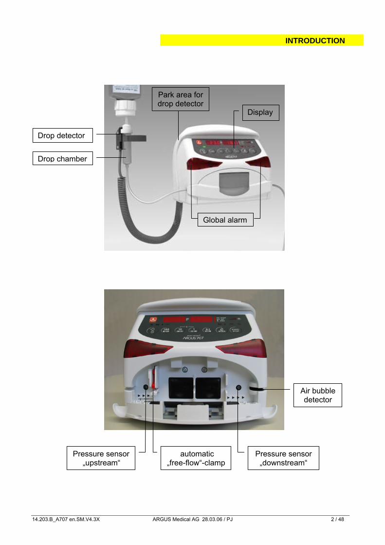
Global alarm
Display
Drop detector
Drop chamber
Park area for drop detector
Air bubble detector
Pressure sensor „downstream“
automatic „free-flow“-clamp
Pressure sensor „upstream“
INTRODUCTION
14.203.B_A707 en.SM.V4.3X ARGUS Medical AG 28.03.06 / PJ 3 / 48
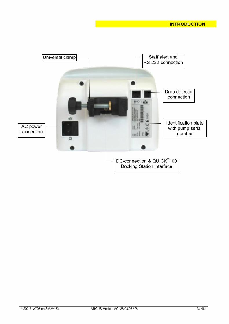
AC power connection
DC-connection & QUICK®100 Docking Station interface
Staff alert and RS-232-connection
Drop detectorconnection
Identification plate with pump serial
number
Universal clamp
INTRODUCTION
14.203.B_A707 en.SM.V4.3X ARGUS Medical AG 28.03.06 / PJ 4 / 48
1. INTRODUCTION
1.1. General
IMPORTANT! This service manual is intended for the exclusive use of authorized persons who have been trained by ARGUS Medical AG in the maintenance and repair of the ARGUS 707 V infusion pump. The service manual is meant to be used together with the user manual.
IMPORTANT! ARGUS Medical AG shall not assume any responsibility for any manipulations which have been carried out on the ARGUS 707 V infusion pump by a non-authorized person. CAUTION! The ARGUS 707 V infusion pump may only be used with spare parts, accessories, consumables and IV-sets with Luer-Lock connections recommended by ARGUS Medical AG. The functional safety of the pump is not guaranteed if non approved materials are used. The safety of the patient may be endangered.
This manual contains the latest data available. It is subject to further modifications in accordance with technical improvements.
2. PUMP CONFIGURATIONS
2.1. General
CAUTION! The configuration possibilities with the “ARGUS service” PC utility tool and without PC assistance constitute a modification of the pump and may only be carried out by authorized persons!
CAUTION! After changing the configuration a function check and a control measurement has to be performed!
PUMP CONFIGURATIONS
14.203.B_A707 en.SM.V4.3X ARGUS Medical AG 28.03.06 / PJ 5 / 48
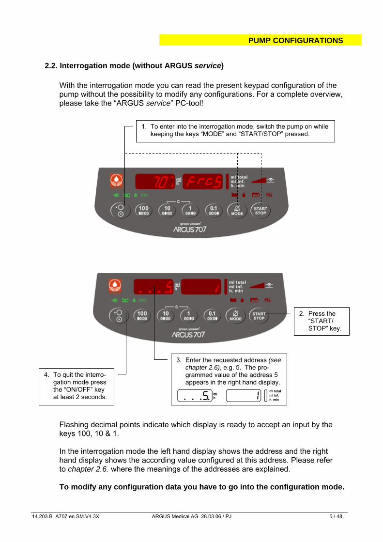
2. Press the “START/
STOP” key.
4. To quit the interro-gation mode press the “ON/OFF” key at least 2 seconds.
3. Enter the requested address (see chapter 2.6), e.g. 5. The pro-grammed value of the address 5 appears in the right hand display.
2.2. Interrogation mode (without ARGUS service) With the interrogation mode you can read the present keypad configuration of the pump without the possibility to modify any configurations. For a complete overview, please take the “ARGUS service” PC-tool! Flashing decimal points indicate which display is ready to accept an input by the keys 100, 10 & 1. In the interrogation mode the left hand display shows the address and the right hand display shows the according value configured at this address. Please refer to chapter 2.6. where the meanings of the addresses are explained. To modify any configuration data you have to go into the configuration mode.
1. To enter into the interrogation mode, switch the pump on while keeping the keys “MODE” and “START/STOP” pressed.
707 RoP g
1... .5
PUMP CONFIGURATIONS
14.203.B_A707 en.SM.V4.3X ARGUS Medical AG 28.03.06 / PJ 6 / 48
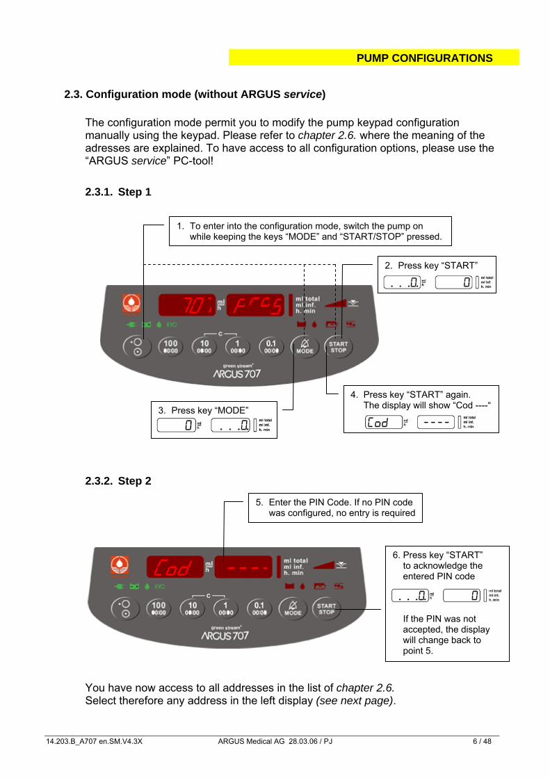
5. Enter the PIN Code. If no PIN code was configured, no entry is required
2. Press key “START”
3. Press key “MODE”
4. Press key “START” again. The display will show “Cod ----“
2.3. Configuration mode (without ARGUS service)
The configuration mode permit you to modify the pump keypad configuration manually using the keypad. Please refer to chapter 2.6. where the meaning of the adresses are explained. To have access to all configuration options, please use the “ARGUS service” PC-tool! 2.3.1. Step 1
2.3.2. Step 2
You have now access to all addresses in the list of chapter 2.6. Select therefore any address in the left display (see next page).
Cod ----
707 p
1. To enter into the configuration mode, switch the pump on while keeping the keys “MODE” and “START/STOP” pressed.
6. Press key “START” to acknowledge the entered PIN code If the PIN was not accepted, the display will change back to point 5.
rog
PUMP CONFIGURATIONS
14.203.B_A707 en.SM.V4.3X ARGUS Medical AG 28.03.06 / PJ 7 / 48
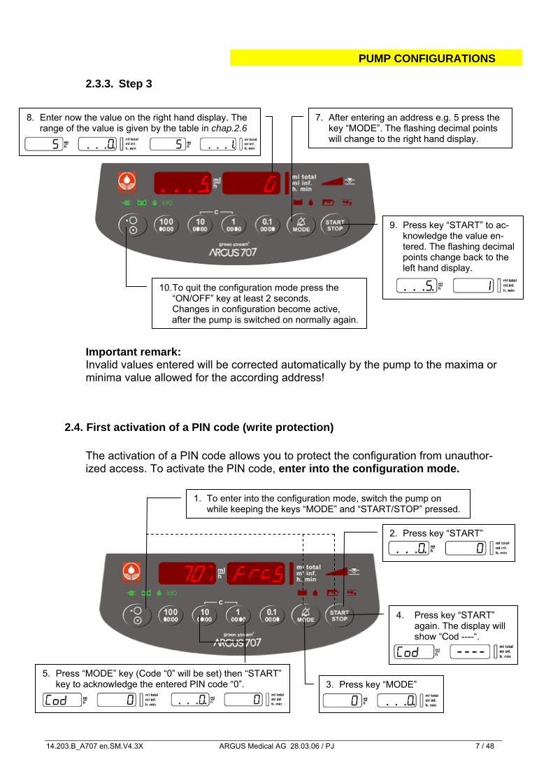
7. After entering an address e.g. 5 press the key “MODE”. The flashing decimal points will change to the right hand display.
9. Press key “START” to ac-knowledge the value en-tered. The flashing decimal points change back to the left hand display.
8. Enter now the value on the right hand display. The range of the value is given by the table in chap.2.6
10. To quit the configuration mode press the “ON/OFF” key at least 2 seconds. Changes in configuration become active,
after the pump is switched on normally again.
2. Press key “START”
3. Press key “MODE”
4. Press key “START” again. The display will show “Cod ----“.
2.3.3. Step 3
Important remark: Invalid values entered will be corrected automatically by the pump to the maxima or minima value allowed for the according address!
2.4. First activation of a PIN code (write protection) The activation of a PIN code allows you to protect the configuration from unauthor-ized access. To activate the PIN code, enter into the configuration mode.
5... .
1. To enter into the configuration mode, switch the pump on while keeping the keys “MODE” and “START/STOP” pressed.
707
5. Press “MODE” key (Code “0” will be set) then “START” key to acknowledge the entered PIN code “0”.
RoP g
0
PUMP CONFIGURATIONS
14.203.B_A707 en.SM.V4.3X ARGUS Medical AG 28.03.06 / PJ 8 / 48
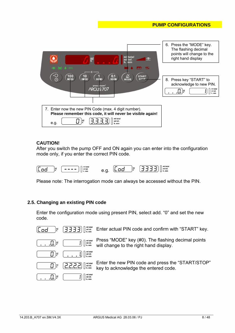
8. Press key “START” to acknowledge to new PIN.
6. Press the “MODE” key. The flashing decimal points will change to the right hand display
CAUTION! After you switch the pump OFF and ON again you can enter into the configuration mode only, if you enter the correct PIN code.
e.g. Please note: The interrogation mode can always be accessed without the PIN.
2.5. Changing an existing PIN code
Enter the configuration mode using present PIN, select add. “0” and set the new code.
Enter actual PIN code and confirm with “START” key.
Press “MODE” key (#0). The flashing decimal points will change to the right hand display.
Enter the new PIN code and press the “START/STOP” key to acknowledge the entered code.
0
7. Enter now the new PIN Code (max. 4 digit number). Please remember this code, it will never be visible again!
e.g.
... . 0
PUMP CONFIGURATIONS
14.203.B_A707 en.SM.V4.3X ARGUS Medical AG 28.03.06 / PJ 9 / 48
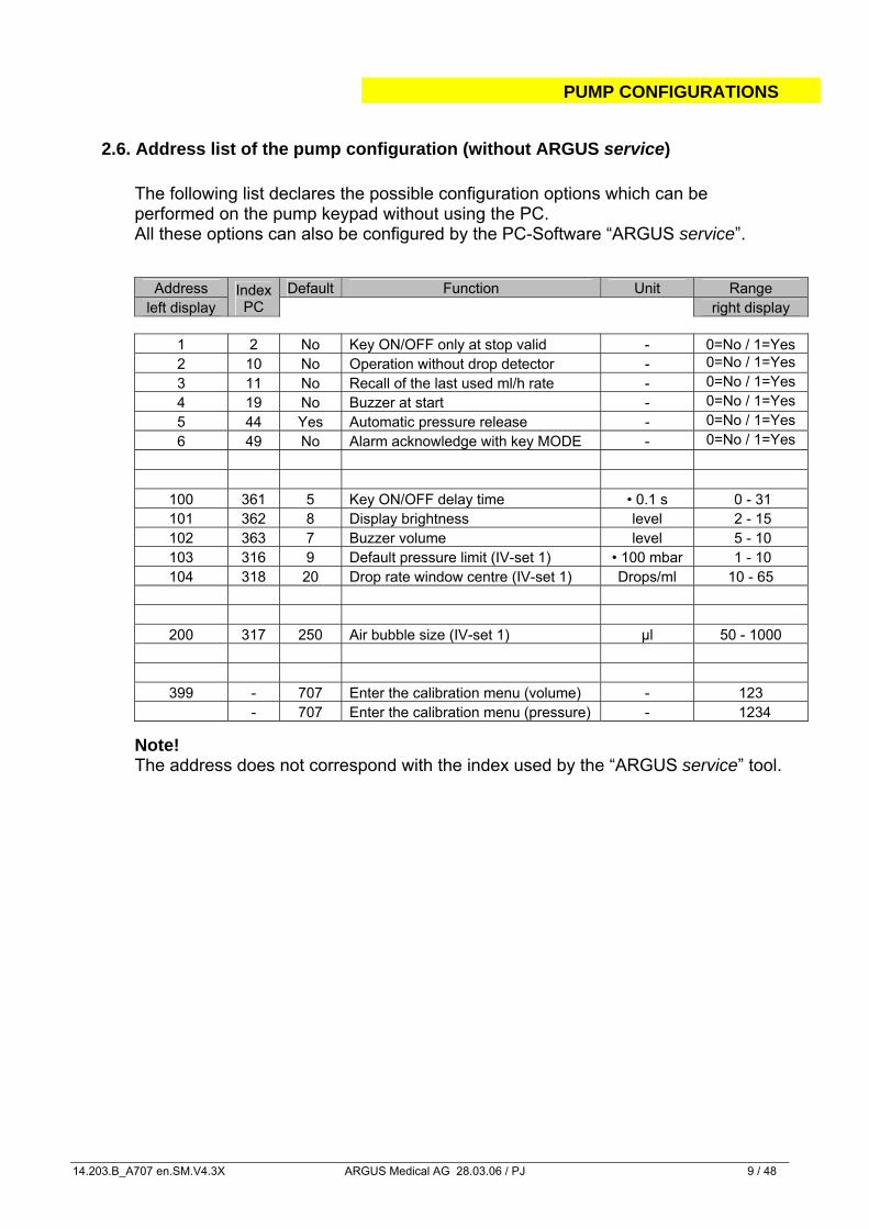
2.6. Address list of the pump configuration (without ARGUS service)
The following list declares the possible configuration options which can be performed on the pump keypad without using the PC. All these options can also be configured by the PC-Software “ARGUS service”.
Address Default Function Unit Range left display
Index PC right display
1 2 No Key ON/OFF only at stop valid - 0=No / 1=Yes 2 10 No Operation without drop detector - 0=No / 1=Yes 3 11 No Recall of the last used ml/h rate - 0=No / 1=Yes 4 19 No Buzzer at start - 0=No / 1=Yes 5 44 Yes Automatic pressure release - 0=No / 1=Yes 6 49 No Alarm acknowledge with key MODE - 0=No / 1=Yes
100 361 5 Key ON/OFF delay time • 0.1 s 0 - 31 101 362 8 Display brightness level 2 - 15 102 363 7 Buzzer volume level 5 - 10 103 316 9 Default pressure limit (IV-set 1) • 100 mbar 1 - 10 104 318 20 Drop rate window centre (IV-set 1) Drops/ml 10 - 65
200 317 250 Air bubble size (IV-set 1) µl 50 - 1000
399 - 707 Enter the calibration menu (volume) - 123 - 707 Enter the calibration menu (pressure) - 1234
Note! The address does not correspond with the index used by the “ARGUS service” tool.
PUMP CONFIGURATIONS
14.203.B_A707 en.SM.V4.3X ARGUS Medical AG 28.03.06 / PJ 10 / 48
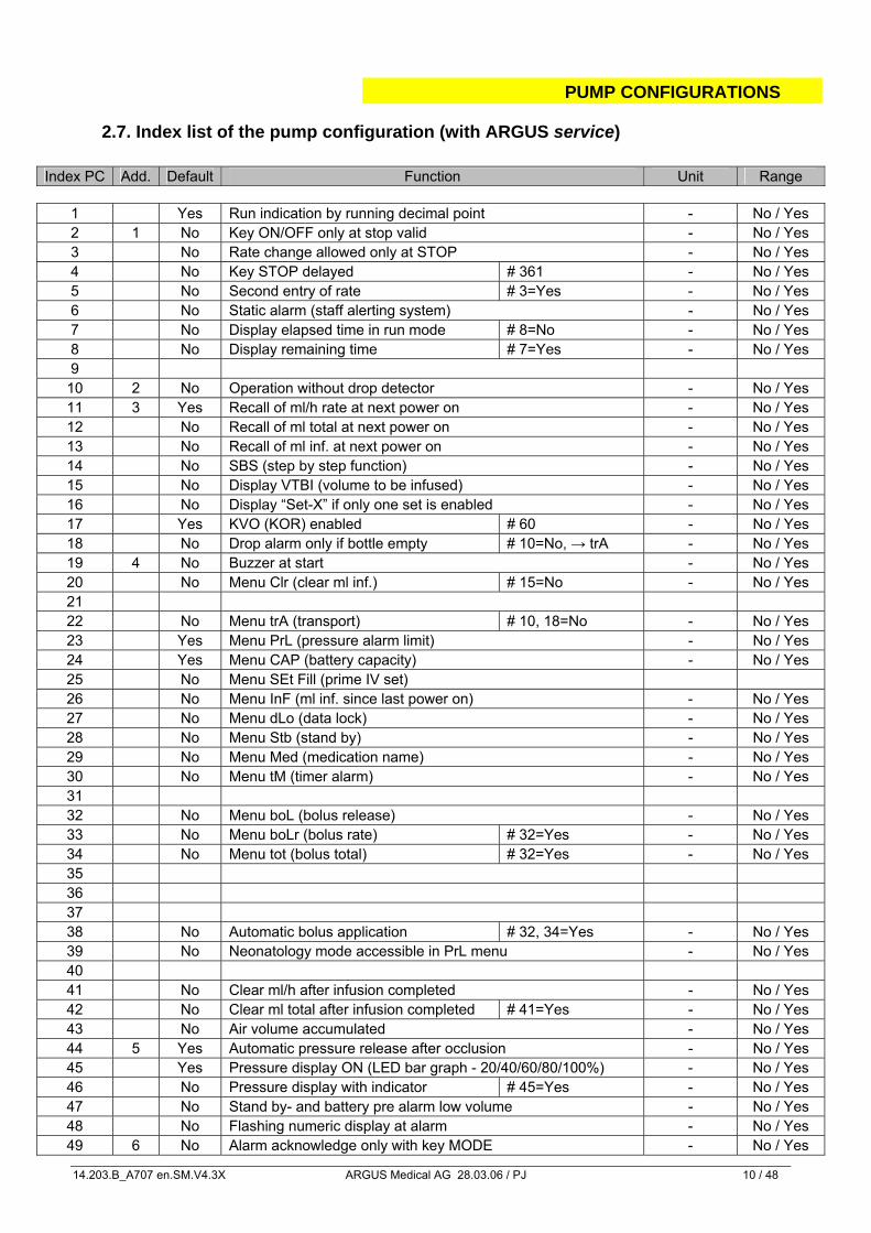
2.7. Index list of the pump configuration (with ARGUS service)
Index PC Add. Default Function Unit Range
1 Yes Run indication by running decimal point - No / Yes 2 1 No Key ON/OFF only at stop valid - No / Yes 3 No Rate change allowed only at STOP - No / Yes 4 No Key STOP delayed # 361 - No / Yes 5 No Second entry of rate # 3=Yes - No / Yes 6 No Static alarm (staff alerting system) - No / Yes 7 No Display elapsed time in run mode # 8=No - No / Yes 8 No Display remaining time # 7=Yes - No / Yes 9
10 2 No Operation without drop detector - No / Yes 11 3 Yes Recall of ml/h rate at next power on - No / Yes 12 No Recall of ml total at next power on - No / Yes 13 No Recall of ml inf. at next power on - No / Yes 14 No SBS (step by step function) - No / Yes 15 No Display VTBI (volume to be infused) - No / Yes 16 No Display “Set-X” if only one set is enabled - No / Yes 17 Yes KVO (KOR) enabled # 60 - No / Yes 18 No Drop alarm only if bottle empty # 10=No, → trA - No / Yes 19 4 No Buzzer at start - No / Yes 20 No Menu Clr (clear ml inf.) # 15=No - No / Yes 21 22 No Menu trA (transport) # 10, 18=No - No / Yes 23 Yes Menu PrL (pressure alarm limit) - No / Yes 24 Yes Menu CAP (battery capacity) - No / Yes 25 No Menu SEt Fill (prime IV set) 26 No Menu InF (ml inf. since last power on) - No / Yes 27 No Menu dLo (data lock) - No / Yes 28 No Menu Stb (stand by) - No / Yes 29 No Menu Med (medication name) - No / Yes 30 No Menu tM (timer alarm) - No / Yes 31 32 No Menu boL (bolus release) - No / Yes 33 No Menu boLr (bolus rate) # 32=Yes - No / Yes 34 No Menu tot (bolus total) # 32=Yes - No / Yes 35 36 37 38 No Automatic bolus application # 32, 34=Yes - No / Yes 39 No Neonatology mode accessible in PrL menu - No / Yes 40 41 No Clear ml/h after infusion completed - No / Yes 42 No Clear ml total after infusion completed # 41=Yes - No / Yes 43 No Air volume accumulated - No / Yes 44 5 Yes Automatic pressure release after occlusion - No / Yes 45 Yes Pressure display ON (LED bar graph - 20/40/60/80/100%) - No / Yes 46 No Pressure display with indicator # 45=Yes - No / Yes 47 No Stand by- and battery pre alarm low volume - No / Yes 48 No Flashing numeric display at alarm - No / Yes 49 6 No Alarm acknowledge only with key MODE - No / Yes
PUMP CONFIGURATIONS
14.203.B_A707 en.SM.V4.3X ARGUS Medical AG 28.03.06 / PJ 11 / 48
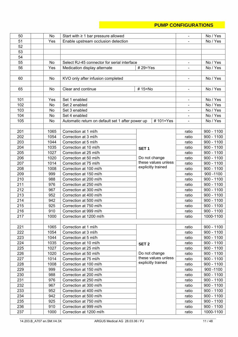
50 No Start with ≥ 1 bar pressure allowed - No / Yes 51 Yes Enable upstream occlusion detection - No / Yes 52 53 54 55 No Select RJ-45 connector for serial interface - No / Yes 56 Yes Medication display alternate # 29=Yes - No / Yes
60 No KVO only after infusion completed - No / Yes
65 No Clear and continue # 15=No - No / Yes
101 Yes Set 1 enabled - No / Yes 102 No Set 2 enabled - No / Yes 103 No Set 3 enabled - No / Yes 104 No Set 4 enabled - No / Yes 105 No Automatic return on default set 1 after power up # 101=Yes - No / Yes
201 1065 Correction at 1 ml/h ratio 900 - 1100 202 1054 Correction at 3 ml/h ratio 900 - 1100 203 1044 Correction at 5 ml/h ratio 900 - 1100 204 1035 Correction at 10 ml/h ratio 900 - 1100 205 1027 Correction at 25 ml/h ratio 900 - 1100 206 1020 Correction at 50 ml/h ratio 900 - 1100 207 1014 Correction at 75 ml/h ratio 900 - 1100 208 1008 Correction at 100 ml/h ratio 900 - 1100 209 999 Correction at 150 ml/h ratio 900 -1100 210 988 Correction at 200 ml/h ratio 900 - 1100 211 976 Correction at 250 ml/h ratio 900 - 1100 212 967 Correction at 300 ml/h ratio 900 - 1100 213 952 Correction at 400 ml/h ratio 900 - 1100 214 942 Correction at 500 ml/h ratio 900 - 1100 215 925 Correction at 750 ml/h ratio 900 - 1100 216 910 Correction at 999 ml/h ratio 900 - 1100 217 1000 Correction at 1200 ml/h
SET 1 Do not change these values unless explicitly trained
ratio 1000-1100
221 1065 Correction at 1 ml/h ratio 900 - 1100 222 1054 Correction at 3 ml/h ratio 900 - 1100 223 1044 Correction at 5 ml/h ratio 900 - 1100 224 1035 Correction at 10 ml/h ratio 900 - 1100 225 1027 Correction at 25 ml/h ratio 900 - 1100 226 1020 Correction at 50 ml/h ratio 900 - 1100 227 1014 Correction at 75 ml/h ratio 900 - 1100 228 1008 Correction at 100 ml/h ratio 900 - 1100 229 999 Correction at 150 ml/h ratio 900 -1100 230 988 Correction at 200 ml/h ratio 900 - 1100 231 976 Correction at 250 ml/h ratio 900 - 1100 232 967 Correction at 300 ml/h ratio 900 - 1100 233 952 Correction at 400 ml/h ratio 900 - 1100 234 942 Correction at 500 ml/h ratio 900 - 1100 235 925 Correction at 750 ml/h ratio 900 - 1100 236 910 Correction at 999 ml/h ratio 900 - 1100 237 1000 Correction at 1200 ml/h
SET 2 Do not change these values unless explicitly trained
ratio 1000-1100
PUMP CONFIGURATIONS
14.203.B_A707 en.SM.V4.3X ARGUS Medical AG 28.03.06 / PJ 12 / 48
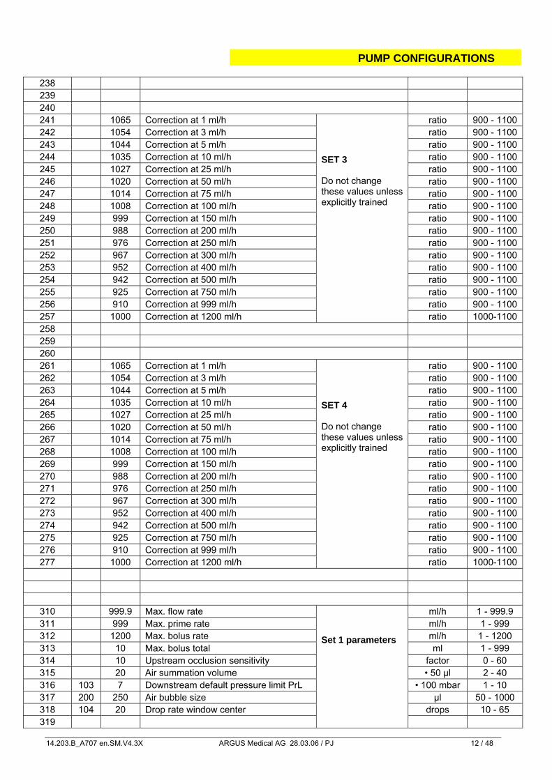
238 239 240 241 1065 Correction at 1 ml/h ratio 900 - 1100 242 1054 Correction at 3 ml/h ratio 900 - 1100 243 1044 Correction at 5 ml/h ratio 900 - 1100 244 1035 Correction at 10 ml/h ratio 900 - 1100 245 1027 Correction at 25 ml/h ratio 900 - 1100 246 1020 Correction at 50 ml/h ratio 900 - 1100 247 1014 Correction at 75 ml/h ratio 900 - 1100 248 1008 Correction at 100 ml/h ratio 900 - 1100 249 999 Correction at 150 ml/h ratio 900 - 1100 250 988 Correction at 200 ml/h ratio 900 - 1100 251 976 Correction at 250 ml/h ratio 900 - 1100 252 967 Correction at 300 ml/h ratio 900 - 1100 253 952 Correction at 400 ml/h ratio 900 - 1100 254 942 Correction at 500 ml/h ratio 900 - 1100 255 925 Correction at 750 ml/h ratio 900 - 1100 256 910 Correction at 999 ml/h ratio 900 - 1100 257 1000 Correction at 1200 ml/h
SET 3 Do not change these values unless explicitly trained
ratio 1000-1100 258 259 260 261 1065 Correction at 1 ml/h ratio 900 - 1100 262 1054 Correction at 3 ml/h ratio 900 - 1100 263 1044 Correction at 5 ml/h ratio 900 - 1100 264 1035 Correction at 10 ml/h ratio 900 - 1100 265 1027 Correction at 25 ml/h ratio 900 - 1100 266 1020 Correction at 50 ml/h ratio 900 - 1100 267 1014 Correction at 75 ml/h ratio 900 - 1100 268 1008 Correction at 100 ml/h ratio 900 - 1100 269 999 Correction at 150 ml/h ratio 900 - 1100 270 988 Correction at 200 ml/h ratio 900 - 1100 271 976 Correction at 250 ml/h ratio 900 - 1100 272 967 Correction at 300 ml/h ratio 900 - 1100 273 952 Correction at 400 ml/h ratio 900 - 1100 274 942 Correction at 500 ml/h ratio 900 - 1100 275 925 Correction at 750 ml/h ratio 900 - 1100 276 910 Correction at 999 ml/h ratio 900 - 1100 277 1000 Correction at 1200 ml/h
SET 4 Do not change these values unless explicitly trained
ratio 1000-1100
310 999.9 Max. flow rate ml/h 1 - 999.9 311 999 Max. prime rate ml/h 1 - 999 312 1200 Max. bolus rate ml/h 1 - 1200 313 10 Max. bolus total ml 1 - 999 314 10 Upstream occlusion sensitivity factor 0 - 60 315 20 Air summation volume • 50 µl 2 - 40 316 103 7 Downstream default pressure limit PrL • 100 mbar 1 - 10 317 200 250 Air bubble size µl 50 - 1000 318 104 20 Drop rate window center drops 10 - 65 319
Set 1 parameters
PUMP CONFIGURATIONS
14.203.B_A707 en.SM.V4.3X ARGUS Medical AG 28.03.06 / PJ 13 / 48
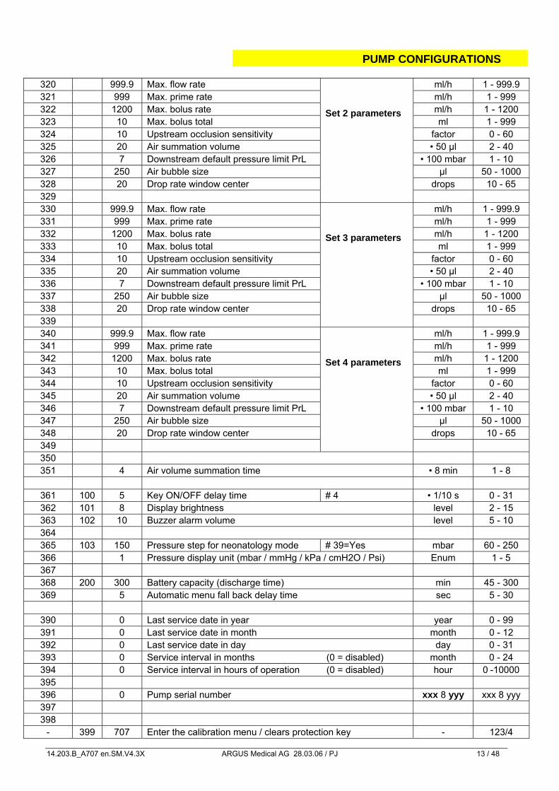
320 999.9 Max. flow rate ml/h 1 - 999.9 321 999 Max. prime rate ml/h 1 - 999 322 1200 Max. bolus rate ml/h 1 - 1200 323 10 Max. bolus total ml 1 - 999 324 10 Upstream occlusion sensitivity factor 0 - 60 325 20 Air summation volume • 50 µl 2 - 40 326 7 Downstream default pressure limit PrL • 100 mbar 1 - 10 327 250 Air bubble size µl 50 - 1000 328 20 Drop rate window center drops 10 - 65 329
Set 2 parameters
330 999.9 Max. flow rate ml/h 1 - 999.9 331 999 Max. prime rate ml/h 1 - 999 332 1200 Max. bolus rate ml/h 1 - 1200 333 10 Max. bolus total ml 1 - 999 334 10 Upstream occlusion sensitivity factor 0 - 60 335 20 Air summation volume • 50 µl 2 - 40 336 7 Downstream default pressure limit PrL • 100 mbar 1 - 10 337 250 Air bubble size µl 50 - 1000 338 20 Drop rate window center drops 10 - 65 339
Set 3 parameters
340 999.9 Max. flow rate ml/h 1 - 999.9 341 999 Max. prime rate ml/h 1 - 999 342 1200 Max. bolus rate ml/h 1 - 1200 343 10 Max. bolus total ml 1 - 999 344 10 Upstream occlusion sensitivity factor 0 - 60 345 20 Air summation volume • 50 µl 2 - 40 346 7 Downstream default pressure limit PrL • 100 mbar 1 - 10 347 250 Air bubble size µl 50 - 1000 348 20 Drop rate window center drops 10 - 65 349
Set 4 parameters
350 351 4 Air volume summation time • 8 min 1 - 8
361 100 5 Key ON/OFF delay time # 4 • 1/10 s 0 - 31 362 101 8 Display brightness level 2 - 15 363 102 10 Buzzer alarm volume level 5 - 10 364 365 103 150 Pressure step for neonatology mode # 39=Yes mbar 60 - 250 366 1 Pressure display unit (mbar / mmHg / kPa / cmH2O / Psi) Enum 1 - 5 367 368 200 300 Battery capacity (discharge time) min 45 - 300 369 5 Automatic menu fall back delay time sec 5 - 30
390 0 Last service date in year year 0 - 99 391 0 Last service date in month month 0 - 12 392 0 Last service date in day day 0 - 31 393 0 Service interval in months (0 = disabled) month 0 - 24 394 0 Service interval in hours of operation (0 = disabled) hour 0 -10000 395 396 0 Pump serial number xxx 8 yyy xxx 8 yyy 397 398
- 399 707 Enter the calibration menu / clears protection key - 123/4
PUMP CONFIGURATIONS
14.203.B_A707 en.SM.V4.3X ARGUS Medical AG 28.03.06 / PJ 14 / 48
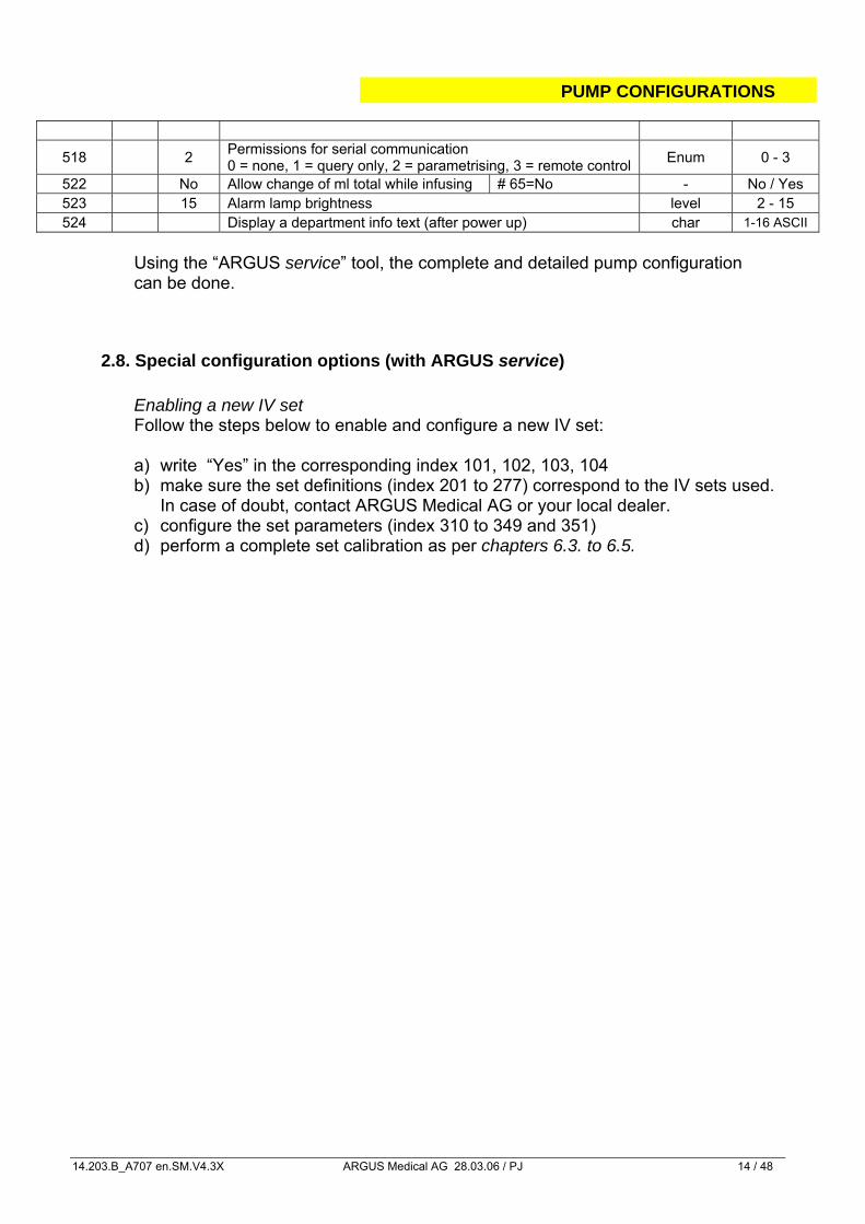
518 2 Permissions for serial communication 0 = none, 1 = query only, 2 = parametrising, 3 = remote control Enum 0 - 3
522 No Allow change of ml total while infusing # 65=No - No / Yes 523 15 Alarm lamp brightness level 2 - 15 524 Display a department info text (after power up) char 1-16 ASCII
Using the “ARGUS service” tool, the complete and detailed pump configuration can be done.
2.8. Special configuration options (with ARGUS service)
Enabling a new IV set Follow the steps below to enable and configure a new IV set: a) write “Yes” in the corresponding index 101, 102, 103, 104 b) make sure the set definitions (index 201 to 277) correspond to the IV sets used.
In case of doubt, contact ARGUS Medical AG or your local dealer. c) configure the set parameters (index 310 to 349 and 351) d) perform a complete set calibration as per chapters 6.3. to 6.5.
PUMP CONFIGURATIONS
14.203.B_A707 en.SM.V4.3X ARGUS Medical AG 28.03.06 / PJ 15 / 48
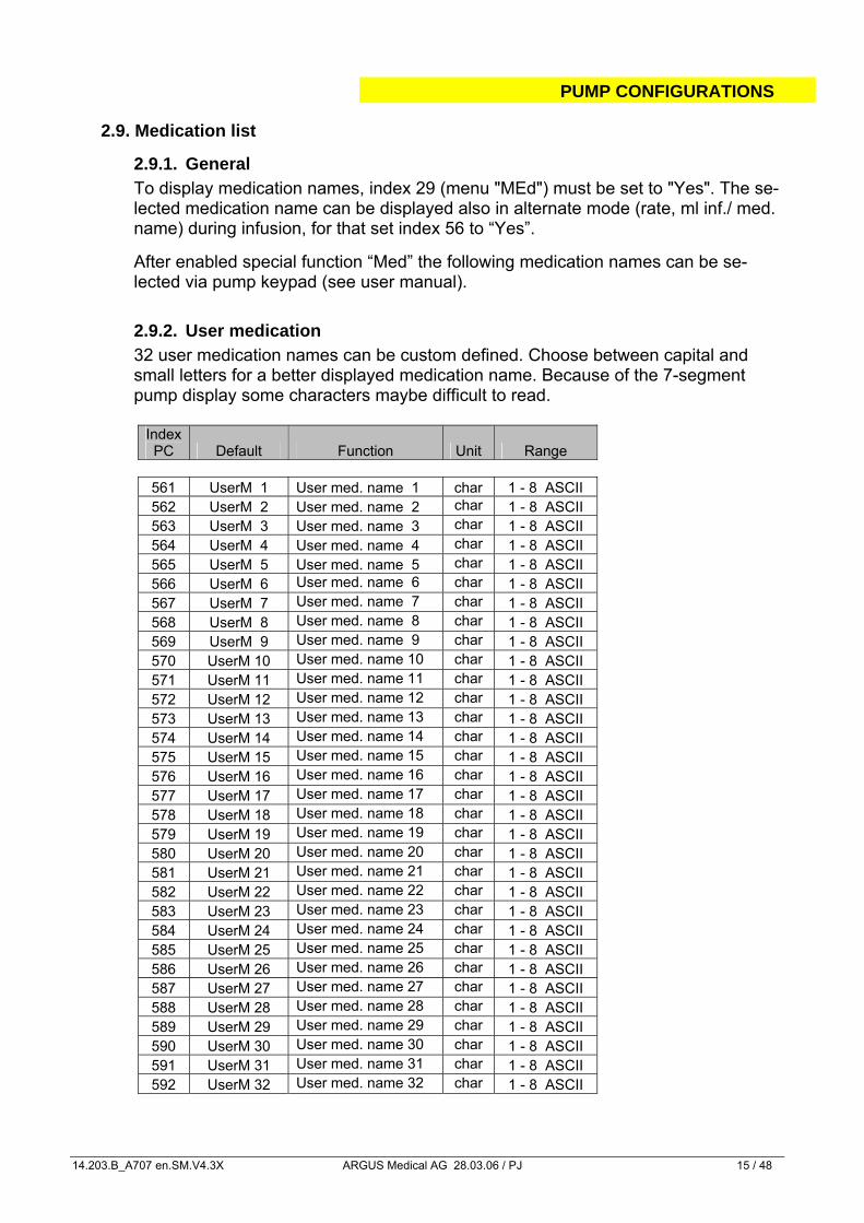
2.9. Medication list
2.9.1. General To display medication names, index 29 (menu "MEd") must be set to "Yes". The se-lected medication name can be displayed also in alternate mode (rate, ml inf./ med. name) during infusion, for that set index 56 to “Yes”. After enabled special function “Med” the following medication names can be se-lected via pump keypad (see user manual).
2.9.2. User medication 32 user medication names can be custom defined. Choose between capital and small letters for a better displayed medication name. Because of the 7-segment pump display some characters maybe difficult to read.
Index PC Default Function Unit Range
561 UserM 1 User med. name 1 char 1 - 8 ASCII 562 UserM 2 User med. name 2 char 1 - 8 ASCII 563 UserM 3 User med. name 3 char 1 - 8 ASCII 564 UserM 4 User med. name 4 char 1 - 8 ASCII 565 UserM 5 User med. name 5 char 1 - 8 ASCII 566 UserM 6 User med. name 6 char 1 - 8 ASCII 567 UserM 7 User med. name 7 char 1 - 8 ASCII 568 UserM 8 User med. name 8 char 1 - 8 ASCII 569 UserM 9 User med. name 9 char 1 - 8 ASCII 570 UserM 10 User med. name 10 char 1 - 8 ASCII 571 UserM 11 User med. name 11 char 1 - 8 ASCII 572 UserM 12 User med. name 12 char 1 - 8 ASCII 573 UserM 13 User med. name 13 char 1 - 8 ASCII 574 UserM 14 User med. name 14 char 1 - 8 ASCII 575 UserM 15 User med. name 15 char 1 - 8 ASCII 576 UserM 16 User med. name 16 char 1 - 8 ASCII 577 UserM 17 User med. name 17 char 1 - 8 ASCII 578 UserM 18 User med. name 18 char 1 - 8 ASCII 579 UserM 19 User med. name 19 char 1 - 8 ASCII 580 UserM 20 User med. name 20 char 1 - 8 ASCII 581 UserM 21 User med. name 21 char 1 - 8 ASCII 582 UserM 22 User med. name 22 char 1 - 8 ASCII 583 UserM 23 User med. name 23 char 1 - 8 ASCII 584 UserM 24 User med. name 24 char 1 - 8 ASCII 585 UserM 25 User med. name 25 char 1 - 8 ASCII 586 UserM 26 User med. name 26 char 1 - 8 ASCII 587 UserM 27 User med. name 27 char 1 - 8 ASCII 588 UserM 28 User med. name 28 char 1 - 8 ASCII 589 UserM 29 User med. name 29 char 1 - 8 ASCII 590 UserM 30 User med. name 30 char 1 - 8 ASCII 591 UserM 31 User med. name 31 char 1 - 8 ASCII 592 UserM 32 User med. name 32 char 1 - 8 ASCII
PUMP CONFIGURATIONS
14.203.B_A707 en.SM.V4.3X ARGUS Medical AG 28.03.06 / PJ 16 / 48
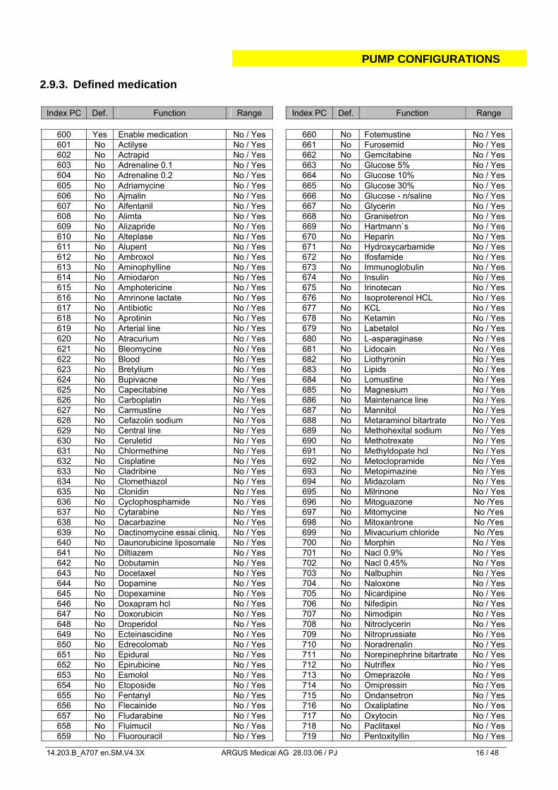
2.9.3. Defined medication Index PC Def. Function Range Index PC Def. Function Range
600 Yes Enable medication No / Yes 660 No Fotemustine No / Yes 601 No Actilyse No / Yes 661 No Furosemid No / Yes 602 No Actrapid No / Yes 662 No Gemcitabine No / Yes 603 No Adrenaline 0.1 No / Yes 663 No Glucose 5% No / Yes 604 No Adrenaline 0.2 No / Yes 664 No Glucose 10% No / Yes 605 No Adriamycine No / Yes 665 No Glucose 30% No / Yes 606 No Ajmalin No / Yes 666 No Glucose - n/saline No / Yes 607 No Alfentanil No / Yes 667 No Glycerin No / Yes 608 No Alimta No / Yes 668 No Granisetron No / Yes 609 No Alizapride No / Yes 669 No Hartmann`s No / Yes 610 No Alteplase No / Yes 670 No Heparin No / Yes 611 No Alupent No / Yes 671 No Hydroxycarbamide No / Yes 612 No Ambroxol No / Yes 672 No Ifosfamide No / Yes 613 No Aminophylline No / Yes 673 No Immunoglobulin No / Yes 614 No Amiodaron No / Yes 674 No Insulin No / Yes 615 No Amphotericine No / Yes 675 No Irinotecan No / Yes 616 No Amrinone lactate No / Yes 676 No Isoproterenol HCL No / Yes 617 No Antibiotic No / Yes 677 No KCL No / Yes 618 No Aprotinin No / Yes 678 No Ketamin No / Yes 619 No Arterial line No / Yes 679 No Labetalol No / Yes 620 No Atracurium No / Yes 680 No L-asparaginase No / Yes 621 No Bleomycine No / Yes 681 No Lidocain No / Yes 622 No Blood No / Yes 682 No Liothyronin No / Yes 623 No Bretylium No / Yes 683 No Lipids No / Yes 624 No Bupivacne No / Yes 684 No Lomustine No / Yes 625 No Capecitabine No / Yes 685 No Magnesium No / Yes 626 No Carboplatin No / Yes 686 No Maintenance line No / Yes 627 No Carmustine No / Yes 687 No Mannitol No / Yes 628 No Cefazolin sodium No / Yes 688 No Metaraminol bitartrate No / Yes 629 No Central line No / Yes 689 No Methohexital sodium No / Yes 630 No Ceruletid No / Yes 690 No Methotrexate No / Yes 631 No Chlormethine No / Yes 691 No Methyldopate hcl No / Yes 632 No Cisplatine No / Yes 692 No Metoclopramide No / Yes 633 No Cladribine No / Yes 693 No Metopimazine No / Yes 634 No Clomethiazol No / Yes 694 No Midazolam No / Yes 635 No Clonidin No / Yes 695 No Milrinone No / Yes 636 No Cyclophosphamide No / Yes 696 No Mitoguazone No /Yes 637 No Cytarabine No / Yes 697 No Mitomycine No /Yes 638 No Dacarbazine No / Yes 698 No Mitoxantrone No /Yes 639 No Dactinomycine essai cliniq. No / Yes 699 No Mivacurium chloride No /Yes 640 No Daunorubicine liposomale No / Yes 700 No Morphin No / Yes 641 No Diltiazem No / Yes 701 No Nacl 0.9% No / Yes 642 No Dobutamin No / Yes 702 No Nacl 0.45% No / Yes 643 No Docetaxel No / Yes 703 No Nalbuphin No / Yes 644 No Dopamine No / Yes 704 No Naloxone No / Yes 645 No Dopexamine No / Yes 705 No Nicardipine No / Yes 646 No Doxapram hcl No / Yes 706 No Nifedipin No / Yes 647 No Doxorubicin No / Yes 707 No Nimodipin No / Yes 648 No Droperidol No / Yes 708 No Nitroclycerin No / Yes 649 No Ecteinascidine No / Yes 709 No Nitroprussiate No / Yes 650 No Edrecolomab No / Yes 710 No Noradrenalin No / Yes 651 No Epidural No / Yes 711 No Norepinephrine bitartrate No / Yes 652 No Epirubicine No / Yes 712 No Nutriflex No / Yes 653 No Esmolol No / Yes 713 No Omeprazole No / Yes 654 No Etoposide No / Yes 714 No Omipressin No / Yes 655 No Fentanyl No / Yes 715 No Ondansetron No / Yes 656 No Flecainide No / Yes 716 No Oxaliplatine No / Yes 657 No Fludarabine No / Yes 717 No Oxytocin No / Yes 658 No Fluimucil No / Yes 718 No Paclitaxel No / Yes 659 No Fluorouracil No / Yes 719 No Pentoxityllin No / Yes
PUMP CONFIGURATIONS
14.203.B_A707 en.SM.V4.3X ARGUS Medical AG 28.03.06 / PJ 17 / 48
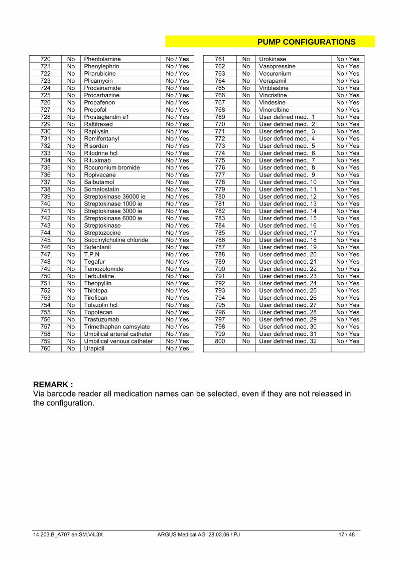
720 No Phentolamine No / Yes 761 No Urokinase No / Yes 721 No Phenylephrin No / Yes 762 No Vasopressine No / Yes 722 No Pirarubicine No / Yes 763 No Vecuronium No / Yes 723 No Plicamycin No / Yes 764 No Verapamil No / Yes 724 No Procainamide No / Yes 765 No Vinblastine No / Yes 725 No Procarbazine No / Yes 766 No Vincristine No / Yes 726 No Propafenon No / Yes 767 No Vindesine No / Yes 727 No Propofol No / Yes 768 No Vinorelbine No / Yes 728 No Prostaglandin e1 No / Yes 769 No User defined med. 1 No / Yes 729 No Raltitrexed No / Yes 770 No User defined med. 2 No / Yes 730 No Rapilysin No / Yes 771 No User defined med. 3 No / Yes 731 No Remifentanyl No / Yes 772 No User defined med. 4 No / Yes 732 No Risordan No / Yes 773 No User defined med. 5 No / Yes 733 No Ritodrine hcl No / Yes 774 No User defined med. 6 No / Yes 734 No Rituximab No / Yes 775 No User defined med. 7 No / Yes 735 No Rocuronium bromide No / Yes 776 No User defined med. 8 No / Yes 736 No Ropivacane No / Yes 777 No User defined med. 9 No / Yes 737 No Salbutamol No / Yes 778 No User defined med. 10 No / Yes 738 No Somatostatin No / Yes 779 No User defined med. 11 No / Yes 739 No Streptokinase 36000 ie No / Yes 780 No User defined med. 12 No / Yes 740 No Streptokinase 1000 ie No / Yes 781 No User defined med. 13 No / Yes 741 No Streptokinase 3000 ie No / Yes 782 No User defined med. 14 No / Yes 742 No Streptokinase 6000 ie No / Yes 783 No User defined med. 15 No / Yes 743 No Streptokinase No / Yes 784 No User defined med. 16 No / Yes 744 No Streptozocine No / Yes 785 No User defined med. 17 No / Yes 745 No Succinylcholine chloride No / Yes 786 No User defined med. 18 No / Yes 746 No Sufentanil No / Yes 787 No User defined med. 19 No / Yes 747 No T.P.N No / Yes 788 No User defined med. 20 No / Yes 748 No Tegafur No / Yes 789 No User defined med. 21 No / Yes 749 No Temozolomide No / Yes 790 No User defined med. 22 No / Yes 750 No Terbutaline No / Yes 791 No User defined med. 23 No / Yes 751 No Theopyllin No / Yes 792 No User defined med. 24 No / Yes 752 No Thiotepa No / Yes 793 No User defined med. 25 No / Yes 753 No Tirofiban No / Yes 794 No User defined med. 26 No / Yes 754 No Tolazolin hcl No / Yes 795 No User defined med. 27 No / Yes 755 No Topotecan No / Yes 796 No User defined med. 28 No / Yes 756 No Trastuzumab No / Yes 797 No User defined med. 29 No / Yes 757 No Trimethaphan camsylate No / Yes 798 No User defined med. 30 No / Yes 758 No Umbilical arterial catheter No / Yes 799 No User defined med. 31 No / Yes 759 No Umbilical venous catheter No / Yes 800 No User defined med. 32 No / Yes 760 No Urapidil No / Yes
REMARK : Via barcode reader all medication names can be selected, even if they are not released in the configuration.
Serial communication of the pump
14.203.B_A707 en.SM.V4.3X ARGUS Medical AG 28.03.06 / PJ 18 / 48
3. SERIAL COMMUNICATION OF THE PUMP
3.1. General The ARGUS 708 Volumetric pump has two serial interfaces on board. One is wired to the docking interface connector and one is connected to the RS232 connector. Important remark! Only the RS232 connector is galvanic separated. The docking interface on the pump is a non galvanic isolated interface! Do not use the docking interface on the pump together with the interface cable (part 10.093) on a patient! If the pump is intended to be monitored as a standalone pump on a patient, use the RS232 connector (RJ45, beside the drop detector connector). To use it, configure this connector as the default serial interface (refer index #55 in the configuration). If the pump is docked into a docking station ARGUS 60 M or ARGUS 100 M, the software switches automatically to the docking interface and the docking station builds the separation device (galvanic isolation) then.
3.2. Serial communication protocol The following characteristics are basics for all the ARGUS devices (volumetric pumps, syringe pumps, docking stations with V4.xx and PCs) which are intended to communicate with the device mentioned in this service manual.
• Full-duplex RS232, currently 4800Baud for single pumps,
9600 Baud for docking stations (also on master/slave-link). • Simple master (host/PC) – slave (device) communication (host does polling). • The host has to repeat the request if there is no valid response. • Uses a checksum (CRC-8). • Binary data transmission, thus no ASCII/text parsing. • Fast & direct communication with pumps on ARGUS docking station. • Specified timeouts during remote mode. • Basic framing technique used as in the Serial Infrared Link Access Protocol (Ir-
LAP) Version 1.1.
Please contact your local distributor or ARGUS Medical AG for the complete serial communication protocol description.
ARGUS service
14.203.B_A707 en.SM.V4.3X ARGUS Medical AG 28.03.06 / PJ 19 / 48
4. ARGUS SERVICE
4.1. General The new ARGUS service utility is a high and user friendly PC software which can configure and upgrade pumps over PC serial COM port. With this Windows based software you can also set pump clock, change PIN code, read and print out history and easily replicate pump configurations, and so on. The modern and clearly struc-tured design of this self-describing PC-tool allows a very easy and rapid modifica-tion of the ARGUS 600 Syringe pump, the ARGUS 707 & 708 Volumetric pump and the ARGUS docking station. This software may be available from your local distribu-tor or directly from ARGUS. REMARK: “ARGUS service” may only be used with software versions greater or equal to 4.00.
CAUTION! The infusion pump has to be disconnected from the patient before and while the se-rial interface cable is connected to the pump.
The connection of the A707 over the serial interface RS-232 can be done by con-necting the interface cable (REF 10.093) to the serial interface outlet of the serial PC-COM port.
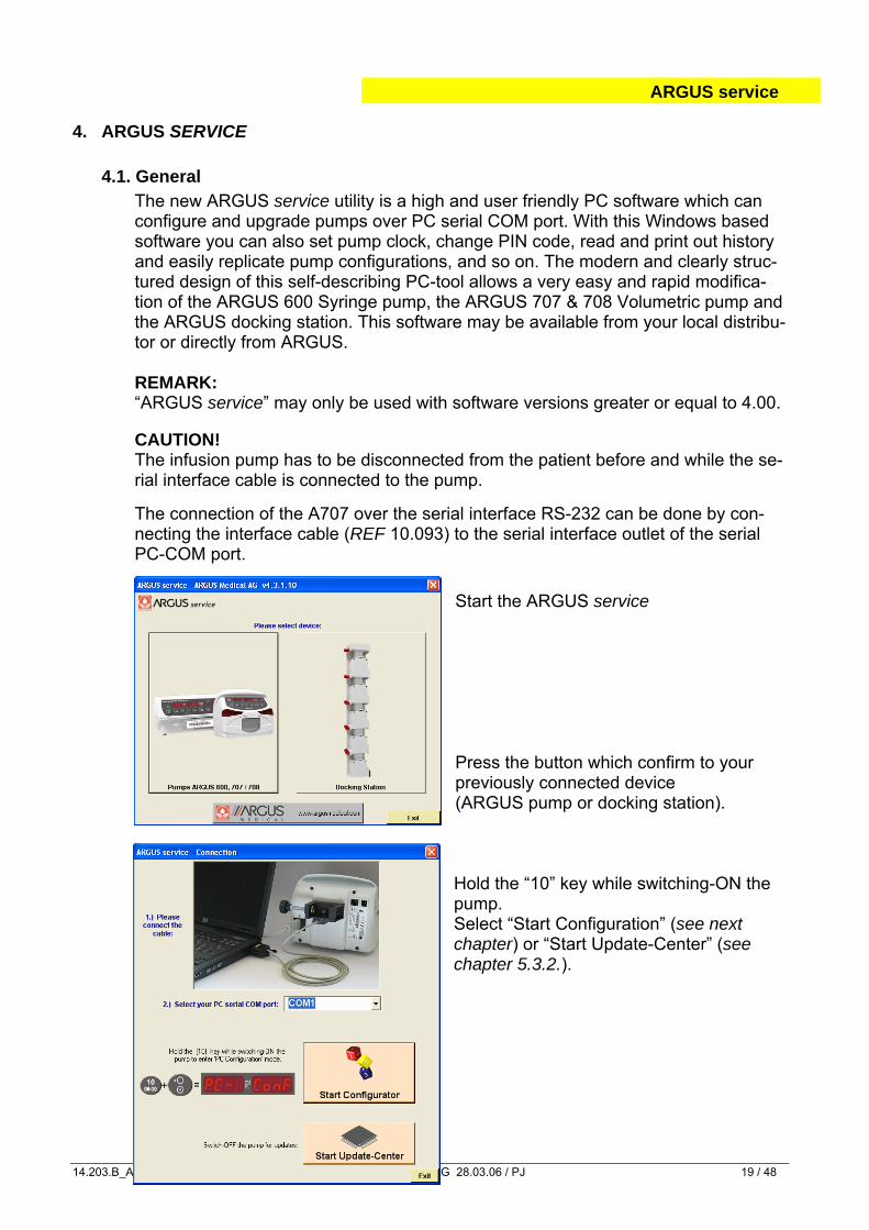
Start the ARGUS service
Press the button which confirm to your previously connected device (ARGUS pump or docking station).
Hold the “10” key while switching-ON the pump. Select “Start Configuration” (see next chapter) or “Start Update-Center” (see chapter 5.3.2.).
ARGUS service
14.203.B_A707 en.SM.V4.3X ARGUS Medical AG 28.03.06 / PJ 20 / 48
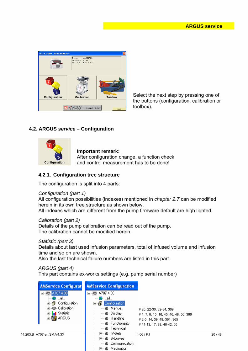
Select the next step by pressing one of the buttons (configuration, calibration or toolbox).
4.2. ARGUS service – Configuration
Important remark: After configuration change, a function check and control measurement has to be done!
4.2.1. Configuration tree structure
The configuration is split into 4 parts: Configuration (part 1) All configuration possibilities (indexes) mentioned in chapter 2.7 can be modified herein in its own tree structure as shown below. All indexes which are different from the pump firmware default are high lighted. Calibration (part 2) Details of the pump calibration can be read out of the pump. The calibration cannot be modified herein. Statistic (part 3) Details about last used infusion parameters, total of infused volume and infusion time and so on are shown. Also the last technical failure numbers are listed in this part. ARGUS (part 4) This part contains ex-works settings (e.g. pump serial number)
# 20, 22-30, 32-34, 369
# 1, 7, 8, 15, 16, 45, 46, 48, 56, 366
# 2-5, 14, 39, 49, 361, 365
# 11-13, 17, 38, 40-42, 60
ARGUS service
14.203.B_A707 en.SM.V4.3X ARGUS Medical AG 28.03.06 / PJ 21 / 48
# 6, 10, 18, 19, 43, 44, 47, 50, 51, 351, 362, 363, 368, 390-394
# 101, 310-318; 102, 320-328; 103, 330-338; 104, 340-348
# 201-217; 221-237; 241-257; 261-277
# 55, 514-517
# 600-800, 561-592
4.2.2. How to edit a configuration The following procedure describes how to edit a pump configuration: 1. Press the green “Edit” button. 2. The software will ask for the pump PIN code as next. The button “Edit” changes
its colour and will be renamed into “Download”. 3. If you want to import a configuration from a file press the “Import” button, other-
wise skip this point. 4. Select “Configuration” in the structure tree in the left upper frame. 5. Select the index group you want to modify by selecting the according structure
tree and the according index. 6. Modify the according index (within the given restrictions shown).
Each value (number) must be acknowledged by the green “Enter” button. Go through point 5 & 6 for all further indexes you want to modify.
7. Press the “Download” button if you want to save the modified configuration on the pump. Otherwise you can save the modified configuration into a file by pressing the “Save” button.
8. Make a functional check on each pump you have configured. Important remark! If a config. has been edited (performed point 1 and 2) once do not switch off the pump! Otherwise the pump will change always into the PC-configuration mode automatically.
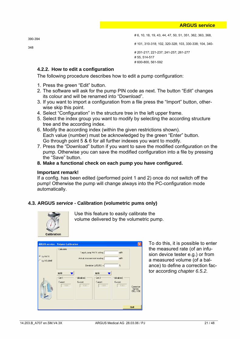
4.3. ARGUS service - Calibration (volumetric pums only)
Use this feature to easily calibrate the volume delivered by the volumetric pump.
To do this, it is possible to enter the measured rate (of an infu-sion device tester e.g.) or from a measured volume (of a bal-ance) to define a correction fac-tor according chapter 6.5.2.
ARGUS service
14.203.B_A707 en.SM.V4.3X ARGUS Medical AG 28.03.06 / PJ 22 / 48
The calculated correction factor can be applied to IV-sets which are released in the config. (index #101 - 104) only. Please be sure which IV-set you want to calibrate before you press the “apply” button. Per ex-works settings, only IV-Set number 1 is calibrated.
Important remark! It is mandatory to perform also a pressure calibration according chapter 6.3. if a new IV-set will be used. We recommend to do a control measurement after changing the correction factor!
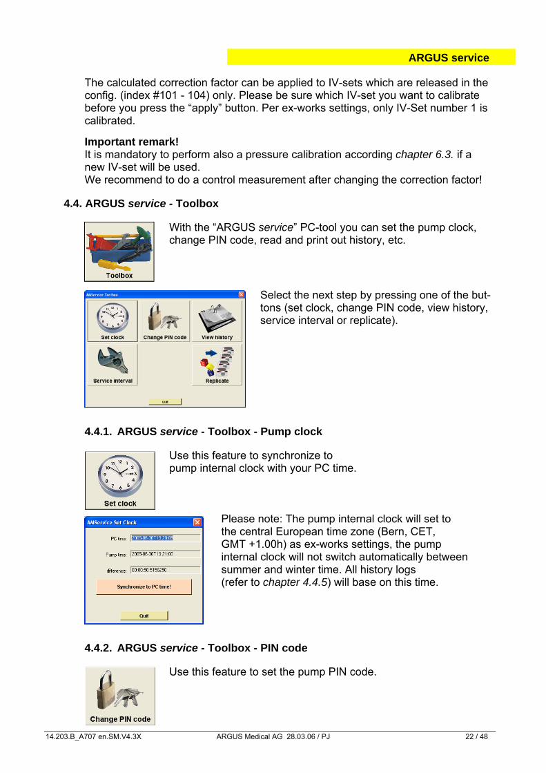
4.4. ARGUS service - Toolbox
With the “ARGUS service” PC-tool you can set the pump clock, change PIN code, read and print out history, etc.
Select the next step by pressing one of the but-tons (set clock, change PIN code, view history, service interval or replicate).
4.4.1. ARGUS service - Toolbox - Pump clock
Use this feature to synchronize to pump internal clock with your PC time.
Please note: The pump internal clock will set to the central European time zone (Bern, CET, GMT +1.00h) as ex-works settings, the pump internal clock will not switch automatically between summer and winter time. All history logs (refer to chapter 4.4.5) will base on this time.
4.4.2. ARGUS service - Toolbox - PIN code
Use this feature to set the pump PIN code.
ARGUS service
14.203.B_A707 en.SM.V4.3X ARGUS Medical AG 28.03.06 / PJ 23 / 48
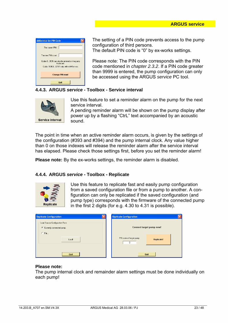
The setting of a PIN code prevents access to the pump configuration of third persons. The default PIN code is “0” by ex-works settings.
Please note: The PIN code corresponds with the PIN code mentioned in chapter 2.3.2. If a PIN code greater than 9999 is entered, the pump configuration can only be accessed using the ARGUS service PC tool.
4.4.3. ARGUS service - Toolbox - Service interval
Use this feature to set a reminder alarm on the pump for the next service interval. A pending reminder alarm will be shown on the pump display after power up by a flashing “CtrL” text accompanied by an acoustic sound.
The point in time when an active reminder alarm occurs, is given by the settings of the configuration (#393 and #394) and the pump internal clock. Any value higher than 0 on those indexes will release the reminder alarm after the service interval has elapsed. Please check those settings first, before you set the reminder alarm! Please note: By the ex-works settings, the reminder alarm is disabled.
4.4.4. ARGUS service - Toolbox - Replicate
Use this feature to replicate fast and easily pump configuration from a saved configuration file or from a pump to another. A con-figuration can only be replicated if the saved configuration (and pump type) corresponds with the firmware of the connected pump in the first 2 digits (for e.g. 4.30 to 4.31 is possible).
Please note: The pump internal clock and remainder alarm settings must be done individually on each pump!
ARGUS service
14.203.B_A707 en.SM.V4.3X ARGUS Medical AG 28.03.06 / PJ 24 / 48
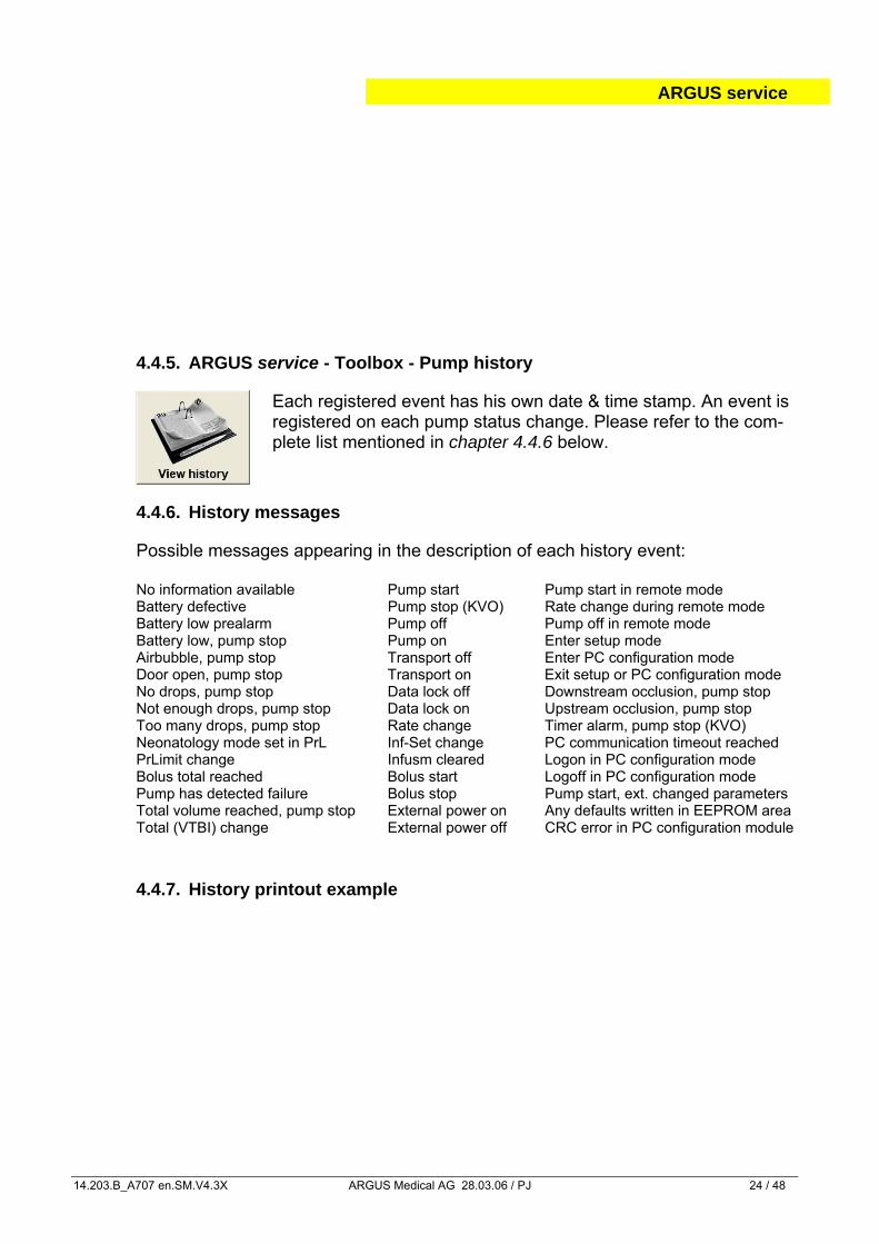
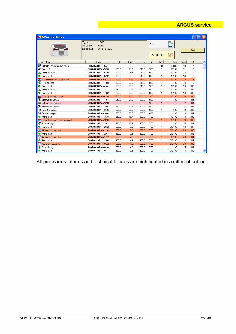
4.4.5. ARGUS service - Toolbox - Pump history
Each registered event has his own date & time stamp. An event is registered on each pump status change. Please refer to the com-plete list mentioned in chapter 4.4.6 below.
4.4.6. History messages
Possible messages appearing in the description of each history event:
No information available Pump start Pump start in remote mode Battery defective Pump stop (KVO) Rate change during remote mode Battery low prealarm Pump off Pump off in remote mode Battery low, pump stop Pump on Enter setup mode Airbubble, pump stop Transport off Enter PC configuration mode Door open, pump stop Transport on Exit setup or PC configuration mode No drops, pump stop Data lock off Downstream occlusion, pump stop Not enough drops, pump stop Data lock on Upstream occlusion, pump stop Too many drops, pump stop Rate change Timer alarm, pump stop (KVO) Neonatology mode set in PrL Inf-Set change PC communication timeout reached PrLimit change Infusm cleared Logon in PC configuration mode Bolus total reached Bolus start Logoff in PC configuration mode Pump has detected failure Bolus stop Pump start, ext. changed parameters Total volume reached, pump stop External power on Any defaults written in EEPROM area Total (VTBI) change External power off CRC error in PC configuration module
4.4.7. History printout example
ARGUS service
14.203.B_A707 en.SM.V4.3X ARGUS Medical AG 28.03.06 / PJ 25 / 48
All pre-alarms, alarms and technical failures are high lighted in a different colour.
SOFTWARE UPDATES
14.203.B_A707 en.SM.V4.3X ARGUS Medical AG 28.03.06 / PJ 26 / 48
5. SOFTWARE UPDATES
5.1. General
This chapter describes the procedure to perform a software update on the ARGUS 707 infusion pump. To check the installed software release in your ARGUS 707 V press the "MODE" key while switching on the pump.
Please refer to your local distributor or ARGUS Medical AG to determine the latest software release able to run on your device hardware.
5.2. Requirements for a software update
To update an ARGUS Medical device, the following items are needed: • PC with Microsoft® Windows™ 2000 or newer, .NET Framework must be installed! • RS-232 serial interface cable (part no. 10.093) • PC configuration tool “ARGUS service” • Latest firmware included in a text file named “A707_xxx.txt”.
(“xxx” is the placeholder for the firmware version). Those items are available from your local distributor or from ARGUS Medical AG.
5.3. Software update procedure
5.3.1. General Please carefully check the software present installed on the pump. If you have a firmware < version 4.xx please follow chapter 5.3.3 to upgrade the firmware.
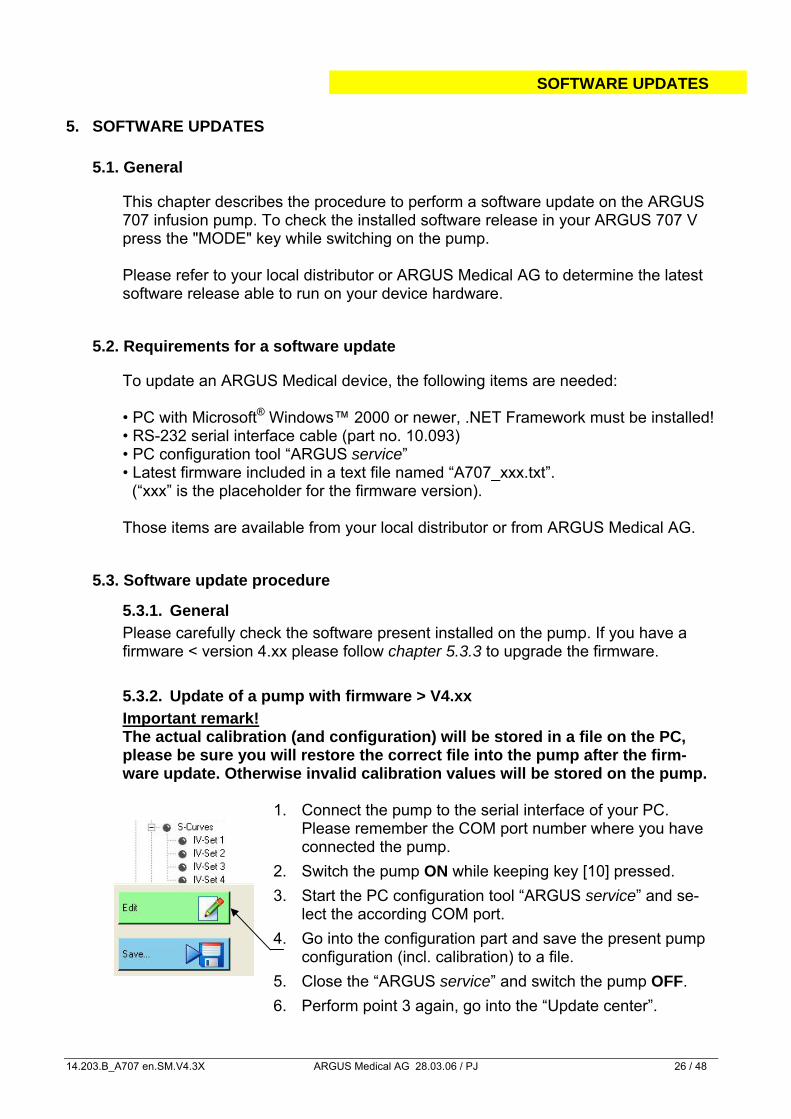
5.3.2. Update of a pump with firmware > V4.xx Important remark! The actual calibration (and configuration) will be stored in a file on the PC, please be sure you will restore the correct file into the pump after the firm-ware update. Otherwise invalid calibration values will be stored on the pump.
1. Connect the pump to the serial interface of your PC.
Please remember the COM port number where you have connected the pump.
2. Switch the pump ON while keeping key [10] pressed.
3. Start the PC configuration tool “ARGUS service” and se-lect the according COM port.
4. Go into the configuration part and save the present pump configuration (incl. calibration) to a file.
5. Close the “ARGUS service” and switch the pump OFF.
6. Perform point 3 again, go into the “Update center”.
SOFTWARE UPDATES
14.203.B_A707 en.SM.V4.3X ARGUS Medical AG 28.03.06 / PJ 27 / 48
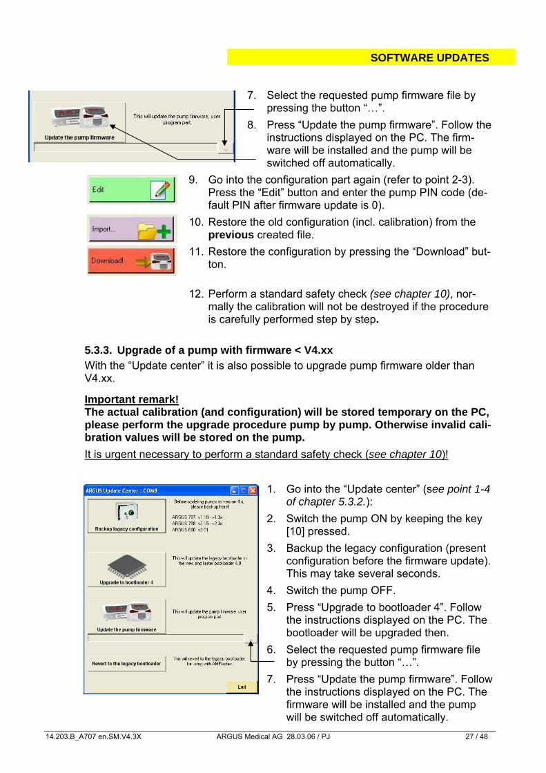
7. Select the requested pump firmware file by
pressing the button “…”.
8. Press “Update the pump firmware”. Follow the instructions displayed on the PC. The firm-ware will be installed and the pump will be switched off automatically.
9. Go into the configuration part again (refer to point 2-3). Press the “Edit” button and enter the pump PIN code (de-fault PIN after firmware update is 0).
10. Restore the old configuration (incl. calibration) from the previous created file.
11. Restore the configuration by pressing the “Download” but-ton.
12. Perform a standard safety check (see chapter 10), nor-mally the calibration will not be destroyed if the procedure is carefully performed step by step.
5.3.3. Upgrade of a pump with firmware < V4.xx With the “Update center” it is also possible to upgrade pump firmware older than V4.xx. Important remark! The actual calibration (and configuration) will be stored temporary on the PC, please perform the upgrade procedure pump by pump. Otherwise invalid cali-bration values will be stored on the pump.
It is urgent necessary to perform a standard safety check (see chapter 10)!
1. Go into the “Update center” (see point 1-4 of chapter 5.3.2.):
2. Switch the pump ON by keeping the key [10] pressed.
3. Backup the legacy configuration (present configuration before the firmware update). This may take several seconds.
4. Switch the pump OFF.
5. Press “Upgrade to bootloader 4”. Follow the instructions displayed on the PC. The bootloader will be upgraded then.
6. Select the requested pump firmware file by pressing the button “…”.
7. Press “Update the pump firmware”. Follow the instructions displayed on the PC. The firmware will be installed and the pump will be switched off automatically.
SOFTWARE UPDATES
14.203.B_A707 en.SM.V4.3X ARGUS Medical AG 28.03.06 / PJ 28 / 48
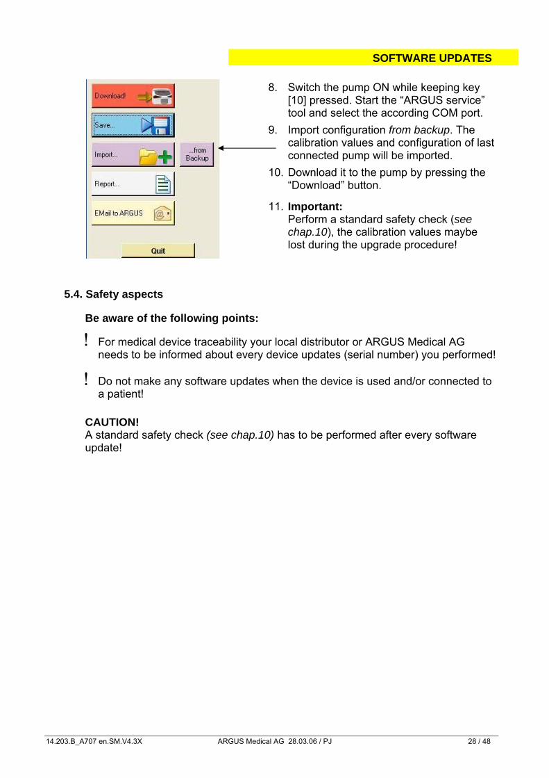
8. Switch the pump ON while keeping key [10] pressed. Start the “ARGUS service” tool and select the according COM port.
9. Import configuration from backup. The calibration values and configuration of last connected pump will be imported.
10. Download it to the pump by pressing the “Download” button.
11. Important: Perform a standard safety check (see chap.10), the calibration values maybe lost during the upgrade procedure!
5.4. Safety aspects
Be aware of the following points:
! For medical device traceability your local distributor or ARGUS Medical AG needs to be informed about every device updates (serial number) you performed!
! Do not make any software updates when the device is used and/or connected to a patient!
CAUTION!
A standard safety check (see chap.10) has to be performed after every software update!
MAINTENANCE
14.203.B_A707 en.SM.V4.3X ARGUS Medical AG 28.03.06 / PJ 29 / 48
6. MAINTENANCE
6.1. General
CAUTION! Only authorized persons who have been trained by ARGUS Medical AG or by the local distributor are allowed to service the ARGUS 707 V infusion pump. In case of repair request, send the unit with the filled out “repair order form” (see chapter 11) to the local distributor. Further information is available from:
ARGUS Medical AG CH-3627 Heimberg / Switzerland E-mail: [email protected]
CAUTION!
The safety standard check (SSC) has to be performed at least every 24 month or after 10'000 hrs of operation. The check has to be done in accordance to the chap-ter 10. No special maintenance of the ARGUS 707 V infusion pump is necessary. There are no wear and tear parts.
6.2. Recalibration
6.2.1. General Unless otherwise specified by the customer, the ARGUS 707 V has been calibrated by the manufacturer with the CODAN L86 PVC (REF 43.4304) infusion set. If a dif-ferent infusion set is used (see recommended list in the appendix of the user man-ual), a recalibration is required.
CAUTION! A new set calibration always requires pressure sensors (up-/ downstream) and a volume calibration (see chapter 6.3 & 6.5)! It is mandatory to execute first the calibration procedure of the pressure sensors and afterwards the volume calibration.
MAINTENANCE
14.203.B_A707 en.SM.V4.3X ARGUS Medical AG 28.03.06 / PJ 30 / 48
6.3. Pressure calibration
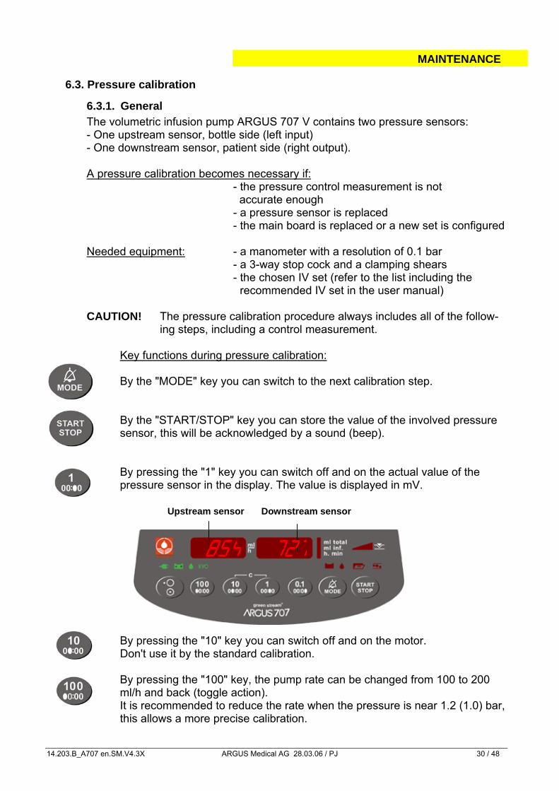
6.3.1. General The volumetric infusion pump ARGUS 707 V contains two pressure sensors: - One upstream sensor, bottle side (left input) - One downstream sensor, patient side (right output).
A pressure calibration becomes necessary if:
- the pressure control measurement is not accurate enough - a pressure sensor is replaced - the main board is replaced or a new set is configured
Needed equipment: - a manometer with a resolution of 0.1 bar - a 3-way stop cock and a clamping shears - the chosen IV set (refer to the list including the
recommended IV set in the user manual)
CAUTION! The pressure calibration procedure always includes all of the follow-ing steps, including a control measurement.
Key functions during pressure calibration: By the "MODE" key you can switch to the next calibration step.
By the "START/STOP" key you can store the value of the involved pressure sensor, this will be acknowledged by a sound (beep).
By pressing the "1" key you can switch off and on the actual value of the pressure sensor in the display. The value is displayed in mV.
By pressing the "10" key you can switch off and on the motor. Don't use it by the standard calibration.
By pressing the "100" key, the pump rate can be changed from 100 to 200 ml/h and back (toggle action). It is recommended to reduce the rate when the pressure is near 1.2 (1.0) bar, this allows a more precise calibration.
Upstream sensor Downstream sensor
727854
MAINTENANCE
14.203.B_A707 en.SM.V4.3X ARGUS Medical AG 28.03.06 / PJ 31 / 48
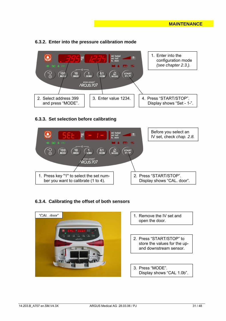
2. Press “START/STOP” to store the values for the up- and downstream sensor.
3. Press “MODE”. Display shows “CAL 1.0b”.
2. Select address 399 and press “MODE”.
4. Press “START/STOP”. Display shows “Set - 1-”.
2. Press “START/STOP”. Display shows “CAL. door”.
1. Press key "1" to select the set num-ber you want to calibrate (1 to 4).
6.3.2. Enter into the pressure calibration mode
6.3.3. Set selection before calibrating
6.3.4. Calibrating the offset of both sensors
1. Enter into the configuration mode (see chapter 2.3.).
1234.399
3. Enter value 1234.
1. Remove the IV set and open the door.
“CAL. door”
Before you select an IV set, check chap. 2.8.
MAINTENANCE
14.203.B_A707 en.SM.V4.3X ARGUS Medical AG 28.03.06 / PJ 32 / 48
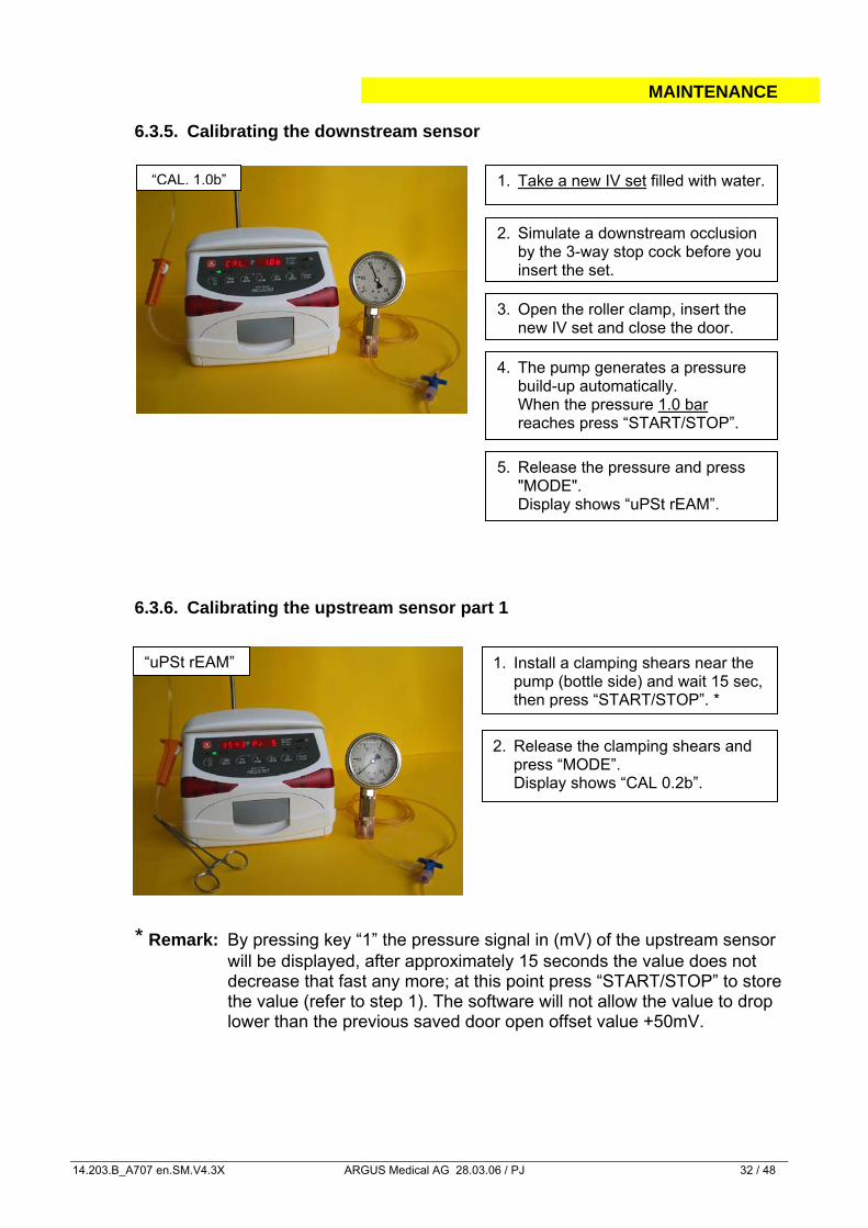
5. Release the pressure and press "MODE".
Display shows “uPSt rEAM”.
3. Open the roller clamp, insert the new IV set and close the door.
1. Take a new IV set filled with water.
1. Install a clamping shears near the pump (bottle side) and wait 15 sec, then press “START/STOP”. *
2. Release the clamping shears and press “MODE”.
Display shows “CAL 0.2b”.
6.3.5. Calibrating the downstream sensor
6.3.6. Calibrating the upstream sensor part 1
* Remark: By pressing key “1” the pressure signal in (mV) of the upstream sensor
will be displayed, after approximately 15 seconds the value does not decrease that fast any more; at this point press “START/STOP” to store the value (refer to step 1). The software will not allow the value to drop lower than the previous saved door open offset value +50mV.
2. Simulate a downstream occlusion by the 3-way stop cock before you insert the set.
4. The pump generates a pressure build-up automatically.
When the pressure 1.0 bar reaches press “START/STOP”.
“uPSt rEAM”
“CAL. 1.0b”
MAINTENANCE
14.203.B_A707 en.SM.V4.3X ARGUS Medical AG 28.03.06 / PJ 33 / 48
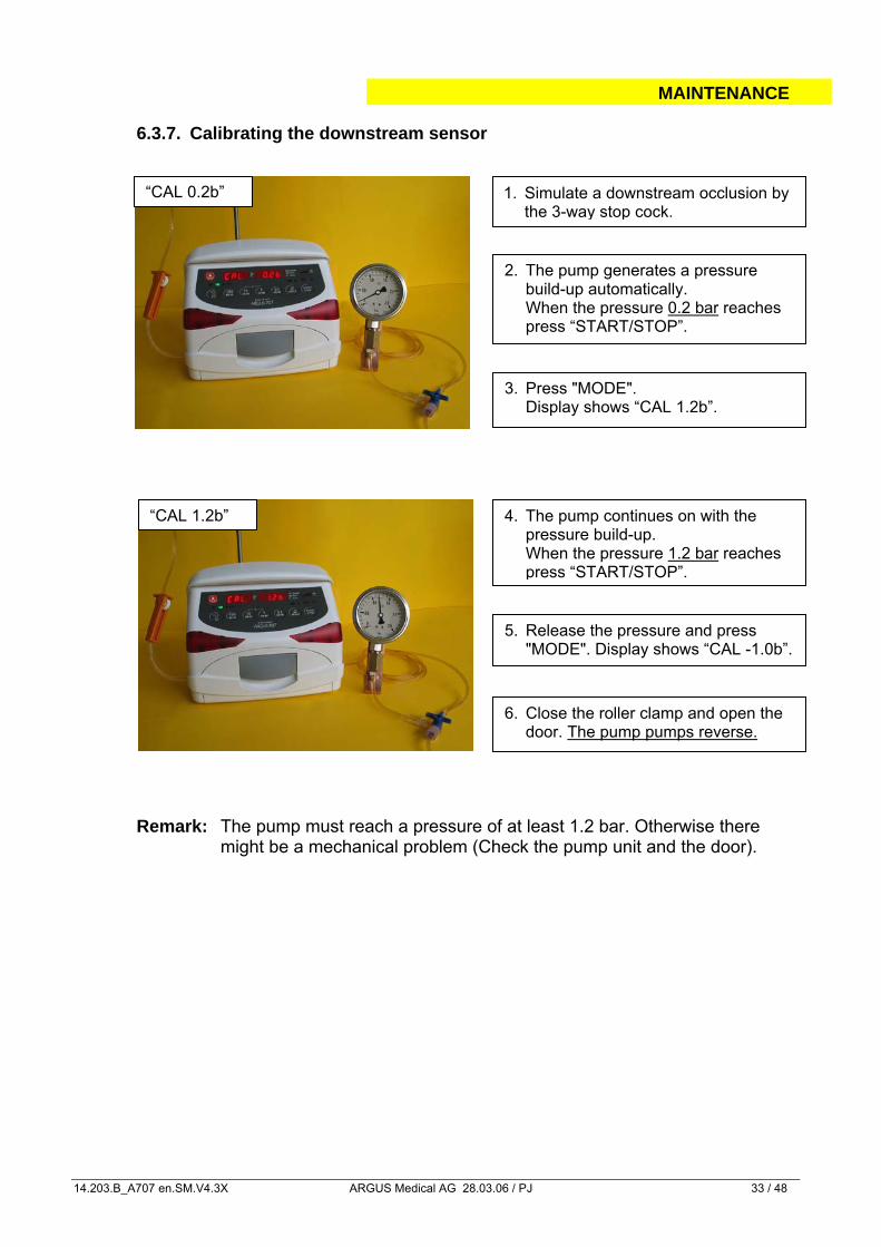
2. The pump generates a pressure build-up automatically. When the pressure 0.2 bar reaches press “START/STOP”.
3. Press "MODE". Display shows “CAL 1.2b”.
4. The pump continues on with the pressure build-up. When the pressure 1.2 bar reaches press “START/STOP”.
5. Release the pressure and press "MODE". Display shows “CAL -1.0b”.
6.3.7. Calibrating the downstream sensor
Remark: The pump must reach a pressure of at least 1.2 bar. Otherwise there might be a mechanical problem (Check the pump unit and the door).
1. Simulate a downstream occlusion by the 3-way stop cock.
6. Close the roller clamp and open the door. The pump pumps reverse.
“CAL 0.2b”
“CAL 1.2b”
MAINTENANCE
14.203.B_A707 en.SM.V4.3X ARGUS Medical AG 28.03.06 / PJ 34 / 48
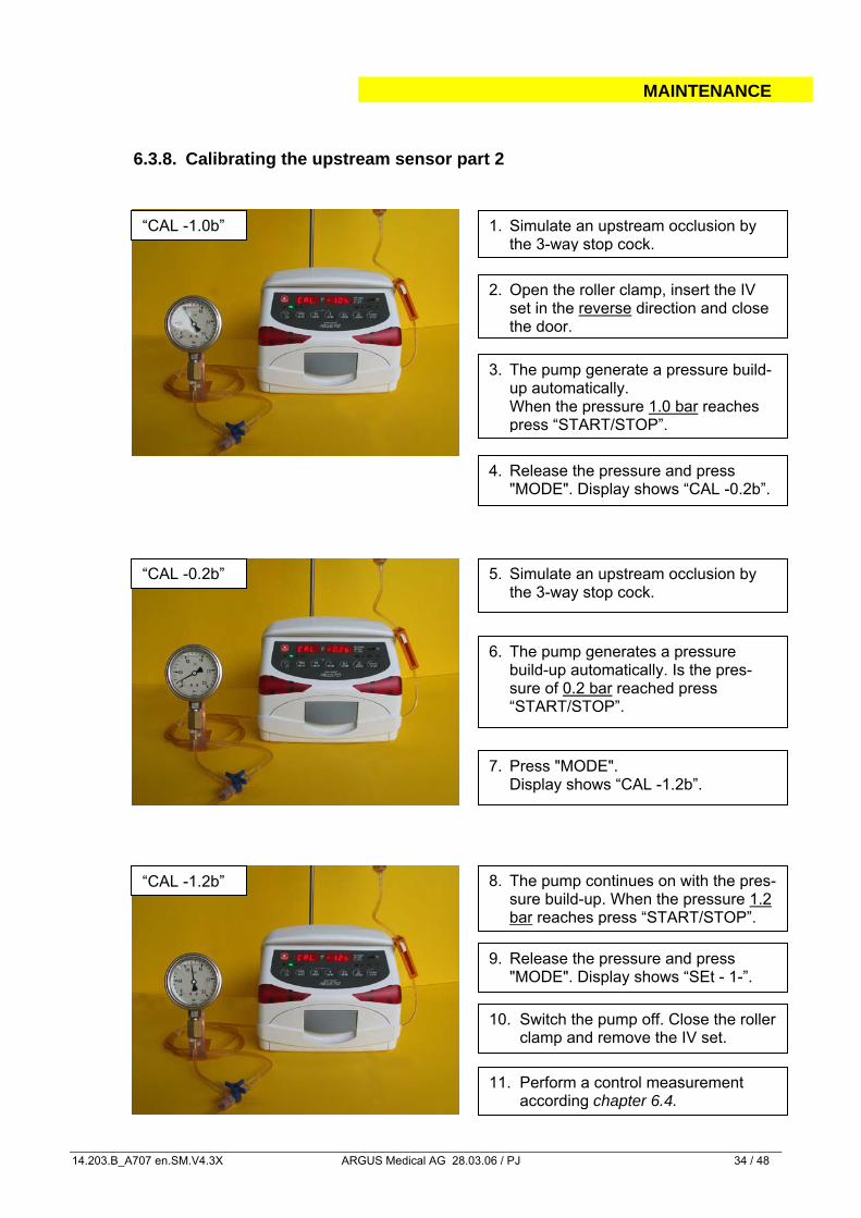
3. The pump generate a pressure build-up automatically.
When the pressure 1.0 bar reaches press “START/STOP”.
4. Release the pressure and press "MODE". Display shows “CAL -0.2b”.
2. Open the roller clamp, insert the IV set in the reverse direction and close the door.
6. The pump generates a pressure build-up automatically. Is the pres-sure of 0.2 bar reached press “START/STOP”.
7. Press "MODE". Display shows “CAL -1.2b”.
5. Simulate an upstream occlusion by the 3-way stop cock.
8. The pump continues on with the pres-sure build-up. When the pressure 1.2 bar reaches press “START/STOP”.
9. Release the pressure and press "MODE". Display shows “SEt - 1-”.
6.3.8. Calibrating the upstream sensor part 2
“CAL -1.0b” 1. Simulate an upstream occlusion by the 3-way stop cock.
“CAL -0.2b”
“CAL -1.2b”
10. Switch the pump off. Close the roller clamp and remove the IV set.
11. Perform a control measurement according chapter 6.4.
MAINTENANCE
14.203.B_A707 en.SM.V4.3X ARGUS Medical AG 28.03.06 / PJ 35 / 48
6.4. Pressure control measurement
6.4.1. Downstream control measurement
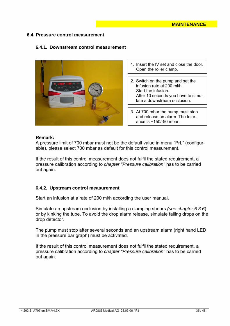
Remark: A pressure limit of 700 mbar must not be the default value in menu “PrL” (configur-able), please select 700 mbar as default for this control measurement. If the result of this control measurement does not fulfil the stated requirement, a pressure calibration according to chapter "Pressure calibration" has to be carried out again.
6.4.2. Upstream control measurement
Start an infusion at a rate of 200 ml/h according the user manual.
Simulate an upstream occlusion by installing a clamping shears (see chapter 6.3.6) or by kinking the tube. To avoid the drop alarm release, simulate falling drops on the drop detector.
The pump must stop after several seconds and an upstream alarm (right hand LED in the pressure bar graph) must be activated.
If the result of this control measurement does not fulfil the stated requirement, a pressure calibration according to chapter "Pressure calibration" has to be carried out again.
1. Insert the IV set and close the door. Open the roller clamp.
2. Switch on the pump and set the infusion rate at 200 ml/h. Start the infusion. After 10 seconds you have to simu-late a downstream occlusion.
3. At 700 mbar the pump must stop and release an alarm. The toler-ance is +150/-50 mbar.
MAINTENANCE
14.203.B_A707 en.SM.V4.3X ARGUS Medical AG 28.03.06 / PJ 36 / 48
6.5. Volume calibration
6.5.1. General On the A707 Volumetric pump it is possible to calibrate up to 4 different IV-Sets. For each IV-set you can define a correction factor, which calibrate the volume deliv-ered.
There are two ways to calibrate the volume delivered by the ARGUS 707 Volumetric pump, select one: • By entering the correction factor • With the internal calibration program of the pump
Needed equipment: balance with a resolution of 0,1g at least
6.5.2. Volume calibration of the pump by defining the correction factor
Please be sure, which IV-set you want to calibrate. If it is not enabled in the configu-ration, please enable it first and select the according IV-set in the normal mode of the pump in menu “Set -x-“.
1. Insert a new IV set (only recommended IV sets may be used, see appendix in the user manual) in the pump and perform a “warm up” infusion of 40 ml at an infusion rate of 999.9 m/h!
2. Infuse now a volume of 30 ml of water in a measuring cup on a zeroed balance at an infusion rate of 250 ml/h.
3. Determine the weight of the delivered water. 4. Connect the pump to a PC and start the ARGUS service PC tool as described
in chapter 4, go into the calibration part of this tool. 5. Refer to chapter 4.3, select “by VOLUME” on the left side in the calibration win-
dow. 6. Enter 30 in the target volume setting field, enter the measured volume (weight)
in the “actual measurement reading” field. The deviation will be calculated by the PC software.
7. Apply this value to the IV-Set you want to calibrate. 8. Perform a control measurement according to the steps 2 & 3 above. Repeat the
calibration procedure if necessary.
MAINTENANCE
14.203.B_A707 en.SM.V4.3X ARGUS Medical AG 28.03.06 / PJ 37 / 48
6.5.3. Volume calibration of set 1 with the pump integrated calibration program
Needed equipment: balance with a resolution of 0,1g at least 1. Insert a new IV set (only recommended IV sets may be used, see ap-
pendix in the user manual) in the pump (filled with water) and connect the infusion line to a measuring cup on a balance.
2. Enter into the configuration mode as described in chapter 2.3. 3. Enter at address 399 the value "123". Press key “START” to acknowl-
edge the entered value. Now you can select your preferred set (in our case set 1).
4. Press the key “START/STOP”. The pump delivers a volume of 40 ml at an infusion rate of 999.9 ml/h (“tArA” is flashing).
5. When “tArA” stops flashing, reset the balance to “0”. 6. Press the key “START/STOP”. The pump will display “tM 432” (infusion
delivery time is 432 seconds). It should now deliver a volume of 30 ml at an infusion rate of 250 ml/h.
7. After the delivery time has elapsed, the pump stops and shows “bAL.” “30.00” in the displays. Enter now the value of the balance, e.g. 29.80g. This value must be within the range of 25.50 – 34.50. Otherwise switch the pump off and re-start the volume calibration.
8. Press the key “START/STOP” to acknowledge the entered value. 9. The pump displays the new correction factor, e.g. “Cor.” ”993”. 10. Press the key “START/STOP” to store the new correction factor ac-
knowledged by a buzzer sound. The pump display changes back to “SEt” “-1-“ again.
11. Switch the pump off. Do not remove the infusion set! 12. Perform a control measurement with an infusion rate of 250 ml/h and an
infusion total of 30 ml. Repeat the calibration procedure if necessary.
For an optimized long time accuracy over 24 hours, we recommend to do a control measurement over 24 hours on a rate of 25 ml/h.
6.6. Pump specifications
Please refer to the user manual for the specifications (chapter 9).
MAINTENANCE
14.203.B_A707 en.SM.V4.3X ARGUS Medical AG 28.03.06 / PJ 38 / 48
6.7. Fault codes A technical failure will be signalled by the pump with a continuous alarm display and a continuous sound. During this state, the fault code which causes the pump to fail can be displayed by pressing the key “MODE”. If the pump was switched OFF after a detected failure, the fault code will be stored in the configuration of the pump (see index 380 - 389 via ARGUS service PC-tool). The possible fault codes registered in the configuration are listed in the table below: Fault Code Failure
F_21 ROM test F_22 ROM check (Runtime) F_23 RAM test/check F_24 XRAM test/check F_25 CPU test F_26 Invalid function menu F_27 EEPROM data invalid F_28 RTC data invalid, no RTC etc. F_29 Stepper motor power test (delayed 5s) F_32 5Volt supply out of range F_33 24Volt supply out of range (delayed 5s) F_37 Downstream pressure sensor test failed (always > 4.7V or < 0.2V, delayed 5s) F_38 Upstream pressure sensor test failed (always > 4.7V or < 0.2V, delayed 5s) * F_39 Downstream pressure sensor test failed (dynamical test failed) F_40 Upstream pressure sensor test failed (dynamical test failed) * F_44 Address invalid for config-eeprom F_45 Address invalid for history-eeprom F_46 Frequency from uC or RTC out of range F_47 Display-print not present F_48 Key(s) too long active F_49 Sensor-print not present F_50 AIL (Air in line) detector test failed F_51 Movement test failed (Home-Pulse < (Hall / Home)) F_52** Movement test failed (Home-Pulse > (Hall / Home)) F_53 More than one rotation at 'STOP' without 'KVO' F_54 Infused sum <> Calculated sum (Rotations) F_55 Frequency calculation F_56 Invalid volume adjustment over time F_57 Rotation (SW overflow) F_58 Internal volume control (10/ml) We recommend replacing the main board in case a fault code is not included in this list above. * Failure released only if configured with upstream sensor (index 51=Yes). ** Fault code F_52 may occur after a software update or if peristaltic is manu-
ally turned during service. In this case, turn the pump off then on again and restart the pump. If a failure free start can be performed, omit this fault code.
REPLACEMENT OF PARTS
14.203.B_A707 en.SM.V4.3X ARGUS Medical AG 28.03.06 / PJ 39 / 48
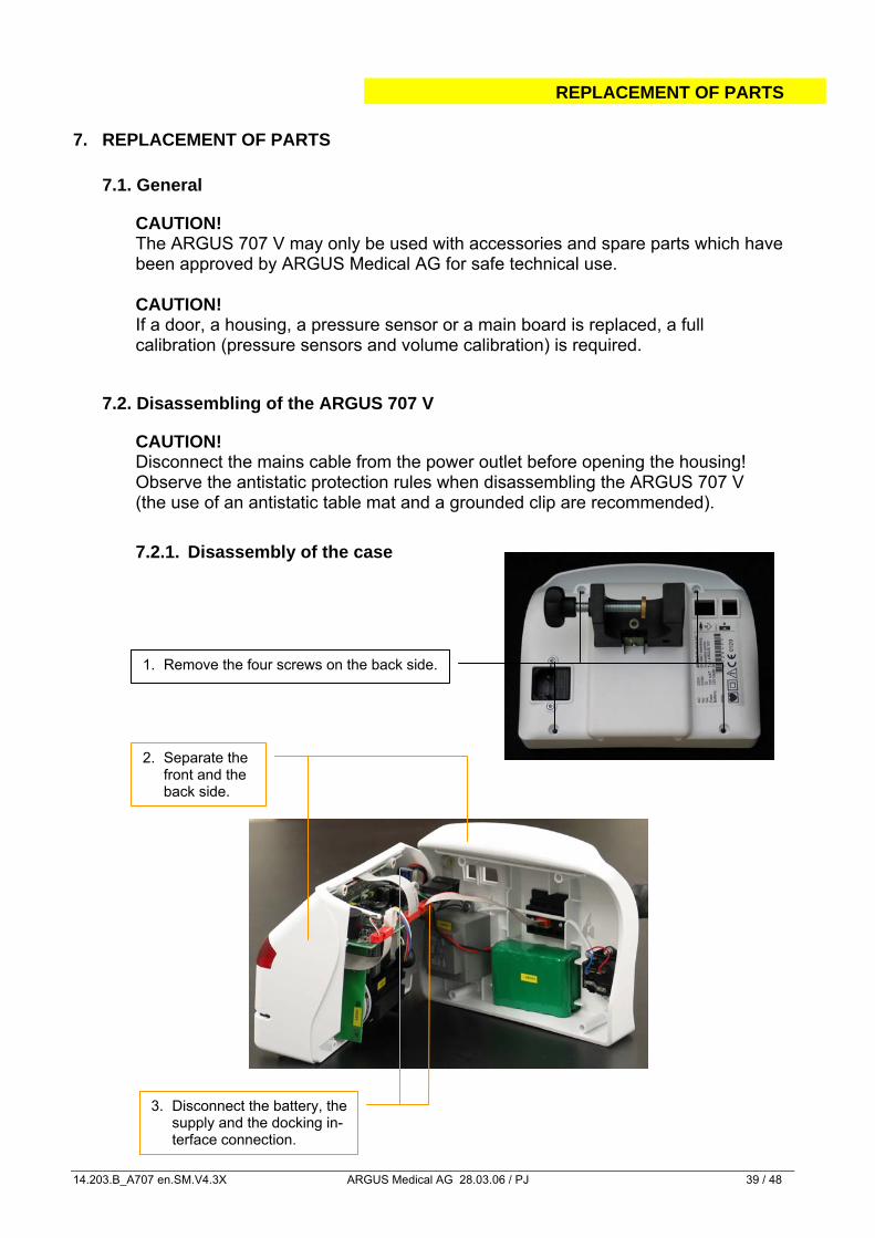
1. Remove the four screws on the back side.
2. Separate the front and the back side.
3. Disconnect the battery, the supply and the docking in-terface connection.
7. REPLACEMENT OF PARTS
7.1. General
CAUTION! The ARGUS 707 V may only be used with accessories and spare parts which have been approved by ARGUS Medical AG for safe technical use.
CAUTION!
If a door, a housing, a pressure sensor or a main board is replaced, a full calibration (pressure sensors and volume calibration) is required.
7.2. Disassembling of the ARGUS 707 V
CAUTION! Disconnect the mains cable from the power outlet before opening the housing! Observe the antistatic protection rules when disassembling the ARGUS 707 V (the use of an antistatic table mat and a grounded clip are recommended). 7.2.1. Disassembly of the case
REPLACEMENT OF PARTS
14.203.B_A707 en.SM.V4.3X ARGUS Medical AG 28.03.06 / PJ 40 / 48
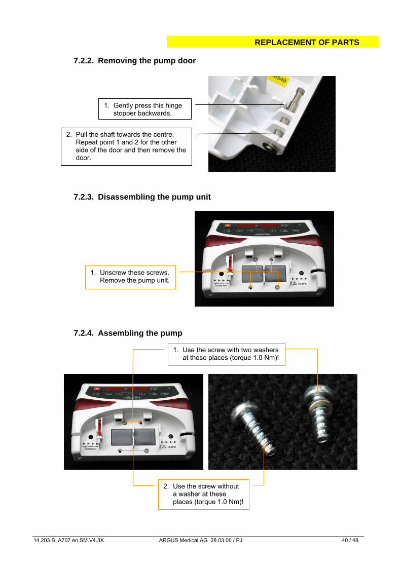
1. Gently press this hinge stopper backwards.
2. Pull the shaft towards the centre. Repeat point 1 and 2 for the other
side of the door and then remove the door.
1. Unscrew these screws. Remove the pump unit.
1. Use the screw with two washers at these places (torque 1.0 Nm)!
2. Use the screw without a washer at these places (torque 1.0 Nm)!
7.2.2. Removing the pump door 7.2.3. Disassembling the pump unit
7.2.4. Assembling the pump
REPLACEMENT OF PARTS
14.203.B_A707 en.SM.V4.3X ARGUS Medical AG 28.03.06 / PJ 41 / 48
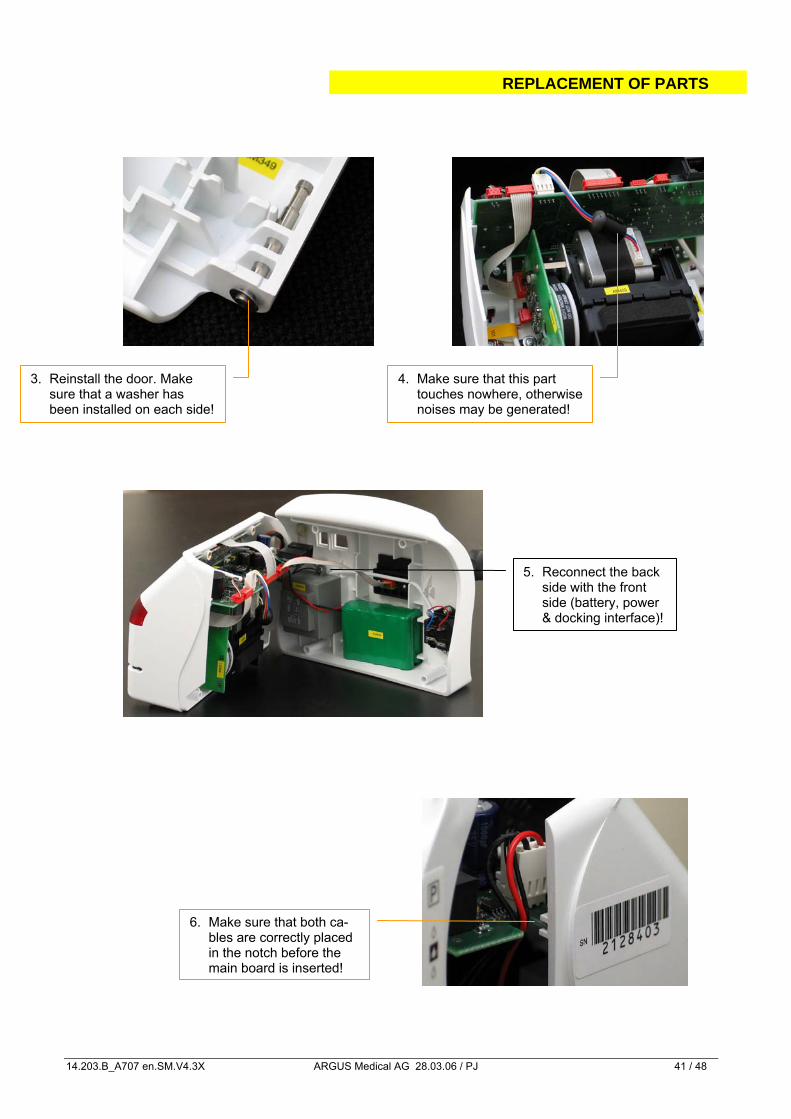
4. Make sure that this part touches nowhere, otherwise noises may be generated!
3. Reinstall the door. Make sure that a washer has been installed on each side!
5. Reconnect the back side with the front side (battery, power & docking interface)!
6. Make sure that both ca-bles are correctly placed in the notch before the main board is inserted!
REPLACEMENT OF PARTS
14.203.B_A707 en.SM.V4.3X ARGUS Medical AG 28.03.06 / PJ 42 / 48
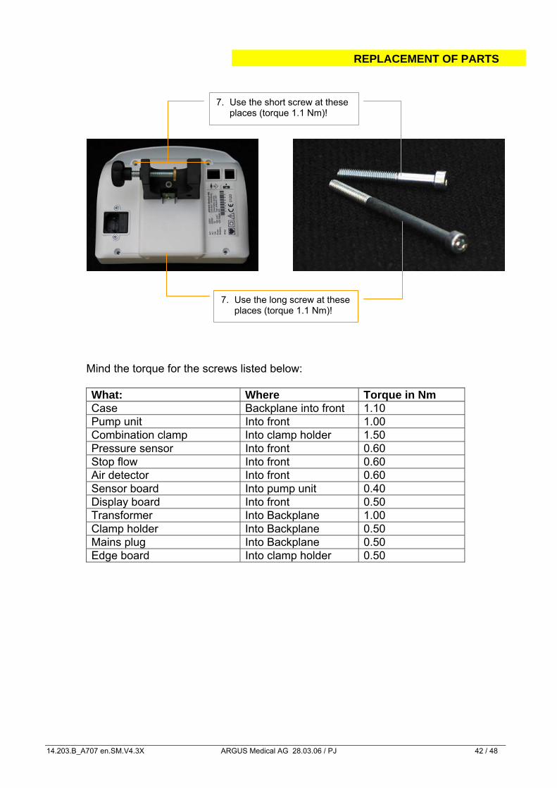
7. Use the short screw at these places (torque 1.1 Nm)!
7. Use the long screw at these places (torque 1.1 Nm)!
Mind the torque for the screws listed below: What: Where Torque in Nm Case Backplane into front 1.10 Pump unit Into front 1.00 Combination clamp Into clamp holder 1.50 Pressure sensor Into front 0.60 Stop flow Into front 0.60 Air detector Into front 0.60 Sensor board Into pump unit 0.40 Display board Into front 0.50 Transformer Into Backplane 1.00 Clamp holder Into Backplane 0.50 Mains plug Into Backplane 0.50 Edge board Into clamp holder 0.50
REPLACEMENT OF PARTS
14.203.B_A707 en.SM.V4.3X ARGUS Medical AG 28.03.06 / PJ 43 / 48
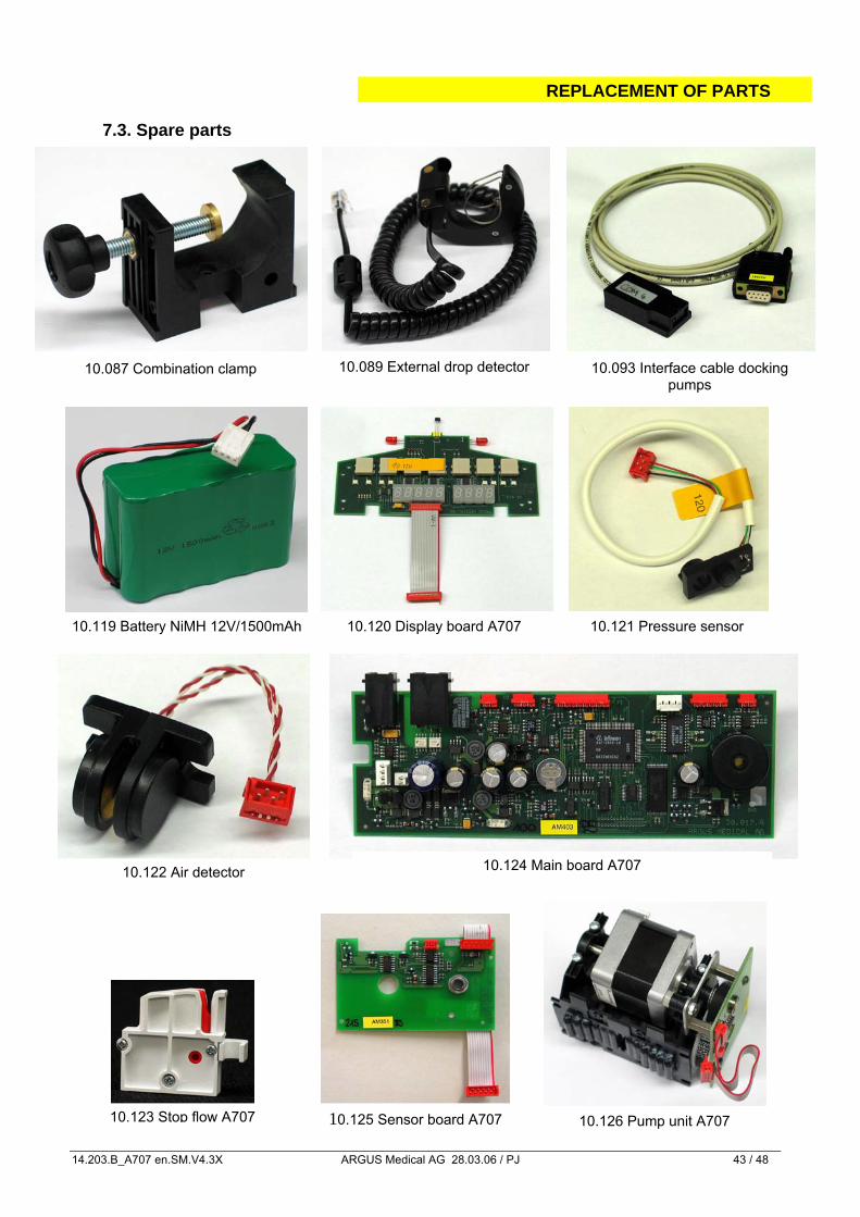
7.3. Spare parts
10.119 Battery NiMH 12V/1500mAh
10.087 Combination clamp 10.089 External drop detector 10.093 Interface cable docking pumps
10.120 Display board A707 10.121 Pressure sensor
10.122 Air detector
10.123 Stop flow A707
10.124 Main board A707
10.125 Sensor board A707 10.126 Pump unit A707
REPLACEMENT OF PARTS
14.203.B_A707 en.SM.V4.3X ARGUS Medical AG 28.03.06 / PJ 44 / 48
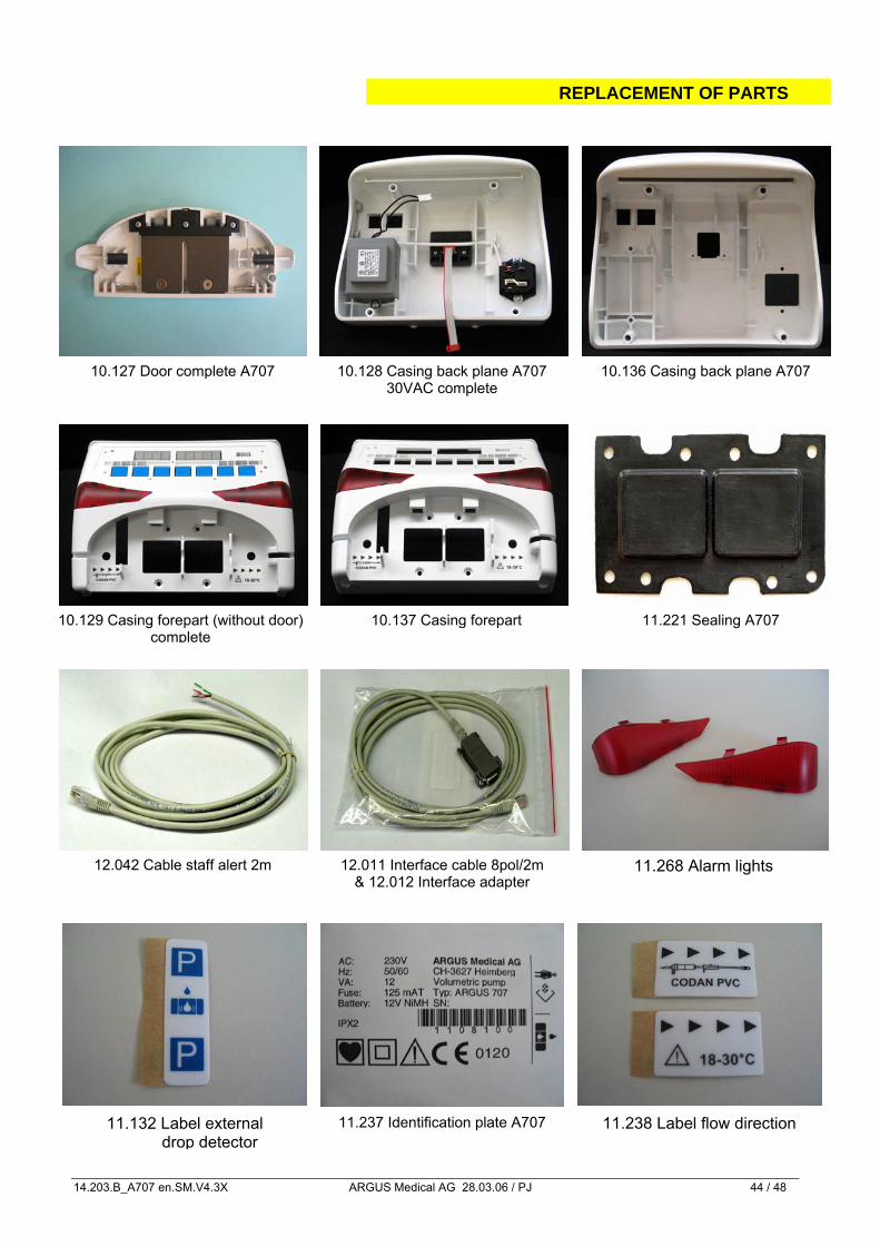
10.127 Door complete A707 10.128 Casing back plane A707 30VAC complete
10.136 Casing back plane A707
10.129 Casing forepart (without door) complete
10.137 Casing forepart
12.011 Interface cable 8pol/2m & 12.012 Interface adapter
12.042 Cable staff alert 2m
11.221 Sealing A707
11.132 Label external drop detector
11.238 Label flow direction
11.268 Alarm lights
11.237 Identification plate A707
REPLACEMENT OF PARTS
14.203.B_A707 en.SM.V4.3X ARGUS Medical AG 28.03.06 / PJ 45 / 48
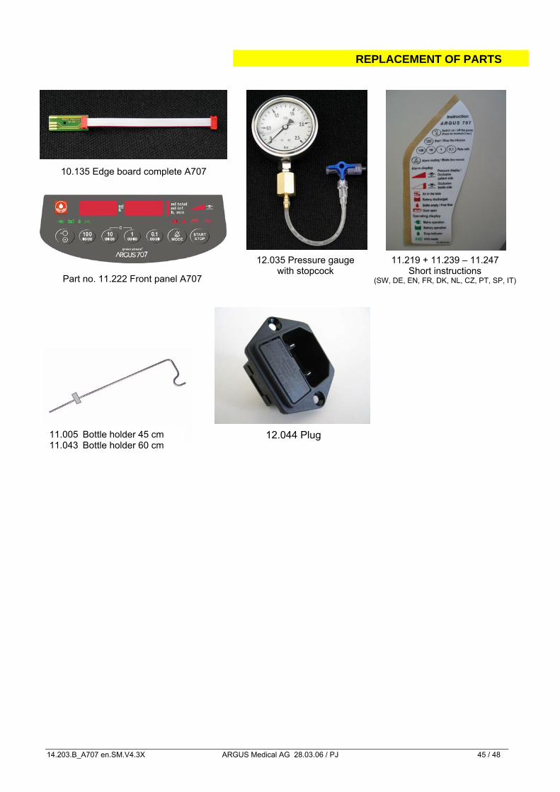
12.035 Pressure gauge with stopcock
10.135 Edge board complete A707
11.005 Bottle holder 45 cm 11.043 Bottle holder 60 cm
12.044 Plug
11.219 + 11.239 – 11.247 Short instructions
(SW, DE, EN, FR, DK, NL, CZ, PT, SP, IT) Part no. 11.222 Front panel A707
WIRING DIAGRAMM
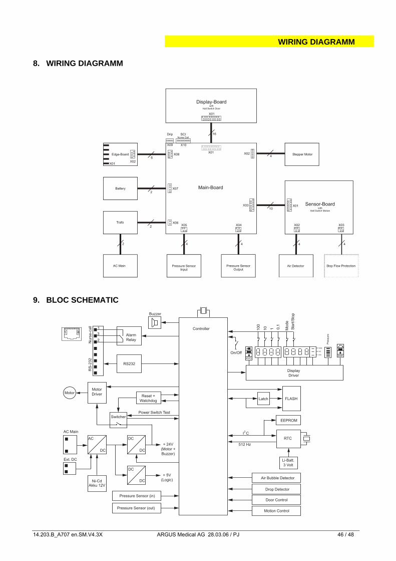
14.203.B_A707 en.SM.V4.3X ARGUS Medical AG 28.03.06 / PJ 46 / 48
8. WIRING DIAGRAMM 9. BLOC SCHEMATIC
FLASH
Buzzer
Ni-CdAkku 12V
Reset +
Watchdog
Alarm
RS232
Relay
Nu
rse
-ca
ll
EEPROM
RTC
Latch
AC
DC
DC
DC
10
0
10 0,1
Mo
de
Sta
rt/S
top
DC
DC
+ 24V
(Motor +
Buzzer)
+ 5V
(Logic)
Controller
Display
Driver
Motion Control
Door ControlPressure Sensor (in)
Pressure Sensor (out)
1
Motor
DriverMotor
Switcher
On/Off
KVODOOR
ml total
h. min
ml inf.
512 Hz
Li-Batt.
3 Volt
RS
-23
2
I C2
Pre
ssu
re
AC Main
Ext. DC
Power Switch Test
Air Bubble Detector
Drop Detector
2
1
31 8
SAFETY STANDARD CHECK
14.203.B_A707 en.SM.V4.3X ARGUS Medical AG 28.03.06 / PJ 47 / 48
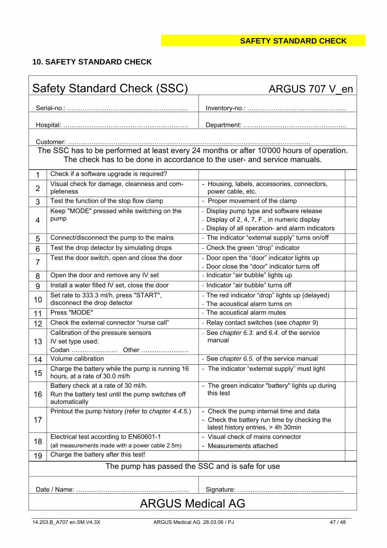
10. SAFETY STANDARD CHECK
Safety Standard Check (SSC) ARGUS 707 V_en
Serial-no.: …………………………....………………..... Inventory-no.: ………………….…..…………….....
Hospital: …………………………………………………. Department: …………………………………….…..
Customer: …………………………………………………………………………………………………. The SSC has to be performed at least every 24 months or after 10'000 hours of operation.
The check has to be done in accordance to the user- and service manuals.
1 Check if a software upgrade is required?
2 Visual check for damage, cleanness and com-pleteness
- Housing, labels, accessories, connectors, power cable, etc.
3 Test the function of the stop flow clamp - Proper movement of the clamp - Display pump type and software release - Display of 2, 4, 7, F., in numeric display 4
Keep "MODE" pressed while switching on the pump
- Display of all operation- and alarm indicators
5 Connect/disconnect the pump to the mains - The indicator “external supply” turns on/off
6 Test the drop detector by simulating drops - Check the green “drop” indicator - Door open the “door” indicator lights up 7 Test the door switch, open and close the door - Door close the “door” indicator turns off
8 Open the door and remove any IV set - Indicator “air bubble” lights up
9 Install a water filled IV set, close the door - Indicator “air bubble” turns off - The red indicator “drop” lights up (delayed) 10 Set rate to 333.3 ml/h, press "START",
disconnect the drop detector - The acoustical alarm turns on
11 Press "MODE" - The acoustical alarm mutes
12 Check the external connector “nurse call” - Relay contact switches (see chapter 9) Calibration of the pressure sensors IV set type used: 13 Codan …………...……. Other ………………….
- See chapter 6.3. and 6.4. of the service manual
14 Volume calibration - See chapter 6.5. of the service manual
15 Charge the battery while the pump is running 16 hours, at a rate of 30.0 ml/h
- The indicator “external supply” must light
Battery check at a rate of 30 ml/h. 16 Run the battery test until the pump switches off
automatically
- The green indicator "battery" lights up during this test
- Check the pump internal time and data 17
Printout the pump history (refer to chapter 4.4.5.) - Check the battery run time by checking the latest history entries, > 4h 30min
Electrical test according to EN60601-1 - Visual check of mains connector 18 (all measurements made with a power cable 2.5m) - Measurements attached
19 Charge the battery after this test!
The pump has passed the SSC and is safe for use
Date / Name: ……...…………………………………….. Signature: ………………………………............…
ARGUS Medical AG
REPAIR ORDER FORM
14.203.B_A707 en.SM.V4.3X ARGUS Medical AG 28.03.06 / PJ 48 / 48
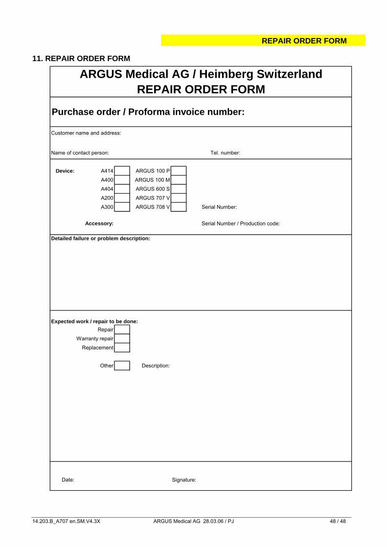
11. REPAIR ORDER FORM
Customer name and address:
Name of contact person: Tel. number:
Device: A414 ARGUS 100 P
A400 ARGUS 100 M
A404 ARGUS 600 S
A200 ARGUS 707 V
A300 ARGUS 708 V Serial Number:
Accessory: Serial Number / Production code:
Detailed failure or problem description:
Expected work / repair to be done:Repair
Warranty repair
Replacement
Other Description:
Date: Signature:
ARGUS Medical AG / Heimberg SwitzerlandREPAIR ORDER FORM
Purchase order / Proforma invoice number: