Embed Size (px)
Citation preview
1
� �
����� ��
1/2 NPT1/2 NPT
�
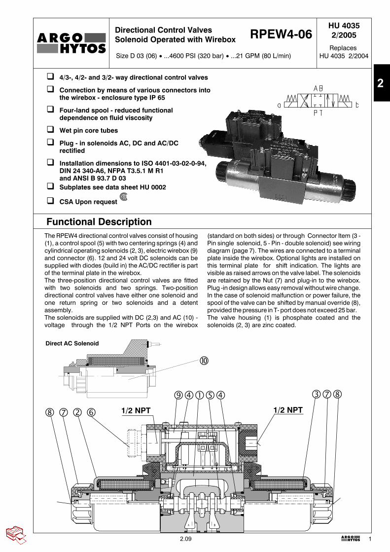
Functional DescriptionThe RPEW4 directional control valves consist of housing(1), a control spool (5) with two centering springs (4) andcylindrical operating solenoids (2, 3), electric wirebox (9)and connector (6). 12 and 24 volt DC solenoids can besupplied with diodes (build in) the AC/DC rectifier is partof the terminal plate in the wirebox.The three-position directional control valves are fittedwith two solenoids and two springs. Two-positiondirectional control valves have either one solenoid andone return spring or two solenoids and a detentassembly.The solenoids are supplied with DC (2,3) and AC (10) -voltage through the 1/2 NPT Ports on the wirebox
(standard on both sides) or through Connector Item (3 -Pin single solenoid, 5 - Pin - double solenoid) see wiringdiagram (page 7). The wires are connected to a terminalplate inside the wirebox. Optional lights are installed onthis terminal plate for shift indication. The lights arevisible as raised arrows on the valve label. The solenoidsare retained by the Nut (7) and plug-in to the wirebox.Plug -in design allows easy removal without wire change.In the case of solenoid malfunction or power failure, thespool of the valve can be shifted by manual override (8),provided the pressure in T- port does not exceed 25 bar.The valve housing (1) is phosphate coated and thesolenoids (2, 3) are zinc coated.
� 4/3-, 4/2- and 3/2- way directional control valves
� Connection by means of various connectors intothe wirebox - enclosure type IP 65
� Four-land spool - reduced functionaldependence on fluid viscosity
� Wet pin core tubes
� Plug - in solenoids AC, DC and AC/DCrectified
� Installation dimensions to ISO 4401-03-02-0-94,DIN 24 340-A6, NFPA T3.5.1 M R1and ANSI B 93.7 D 03
� Subplates see data sheet HU 0002
� CSA Upon request
Direct AC Solenoid
HU 40352/2005
Size D 03 (06) � ...4600 PSI (320 bar) � ...21 GPM (80 L/min)
Directional Control ValvesSolenoid Operated with Wirebox RPEW4-06
ReplacesHU 4035 2/2004
2.09
2
2
HU 4035
RPEW4-06 /
Spool Symbolssee the table spool symbols
Valve Size D 03 (06)
Solenoid OperatedDirectional Control Valveswith Wirebox
Number of Valve Positionstwo positions 2three positions 3
Rated Supply Voltage of Solenoids(at the wirebox terminals)12 V DC / 2.64 A 0120024 V DC / 1.32 A 02400120V AC/60Hz*
*AC coilsorDC coils with rectifier in wirebox
12060
Note: For other voltages consult factory
Type of Solenoid Coil for Wiring Box (Plug-In-Coil)
DC solenoid (DC and AC - rectified) EW1DC solenoid with quenching diodeAC solenoid
EW2EW5
Sealsomit NBRV FPM (Viton)
Orifice in P Portomit without orificeD1 �0.039 inch (1.0 mm)D2 �0.059 inch (1.5 mm)D3 �0.079 inch (2.0 mm)D4 �0.087 inch (2.2 mm)D5 �0.098 inch (2.5 mm)
Manual Overrideomit standardN1 covered with retaining nut*N2 covered with rubber boot*
* for DC voltage only
Wirebox Configurations:
50 Standard wiring box with 1/2 NPT both ends(Either side can be used for wiring, Remove
cover -plug accordingly)51 Standard wiring box with 1/2 NPT both ends
and lights (B- side plugged, A - side covert forshipping)
52 Wiring box with 3 PIN connector ANSI/B93.55Mmounted on A-side (B-side plugged, only for single
solenoid valves)53 Wiring box with 3 PIN connector ANSI/B93.55M
mounted on B-side (A-side plugged, only for singlesolenoid valves)
54 Wiring box with 3 PIN connector ANSI/B93.55Mmounted on A-side with light (B-side plugged,
only for single solenoid valves)55 Wiring box with 3 PIN connector ANSI/B93.55M
mounted on B-side with light (A-side plugged,only for single solenoid valves)
56 Wiring box with 5 PIN connector ANSI/B93.55Mmounted on A-side (B-side plugged, only for double
solenoid valves)57 Wiring box with 5 PIN connector ANSI/B93.55M
mounted on B-side (A-side plugged, only for doublesolenoid valves)
58 Wiring box with 5 PIN connector ANSI/B93.55Mmounted on A-side with light (B-side plugged,
only for double solenoid valves)59 Wiring box with 5 PIN connector ANSI/B93.55M
mounted on B-side with light (A-side plugged,only for double solenoid valves)
Type of WireboxWirebox for DC and AC KWirebox AC rectified (rectifier in wirebox) R
Spool Speed Control Orificeomit without dampingT1 orifice �0.003 inch (0.7 mm) in solenoid** for DC voltage only
Note: For soft shift details / performancesee HU 4010
Order Code
CSA Upon request
2.09
2

3
HU 4035
Type Symbol Crossover Type Symbol Crossover
Technical DataValve size US (mm) D 03 (06)Maximum flow GPM (L/min) see p-Q characteristicsMax. operating pressure at porte P, A, B PSI (bar) 4600 (320)Max. operating pressure at port T PSI (bar) 3000 (210)Pressure drop PSI (bar) see �p-Q characteristics
Hydraulic fluidPetroleum oils (HM, HL, HLP)
Phosphate ester fluids (HFD-R)Fluid temperature range for NBR seals °F (°C) -22 ... +176 (-30 ... +80)Fluid temperature range for FPM seals °F (°C) -4 ... +176 (-20 ... +80)Ambient temperature max. °F (°C) up to +122 (+50)Viscosity range SUS (mm2/s) 98 ... 1840 (20 ... 400)Maximum degree of fluid contamination Class 21/18/15 to ISO 4406 (1999).Max. allowable voltage variation % DC: � 10% / AC: ± 10%Max. switching frequency 1/h 15 000Switching time, on: at �=156 SUS (32 mm2/s) ms DC: 30 ... 50 AC direct: CF AC rec.: 30 ... 40Switching time, off: at �=156 SUS (32 mm2/s) ms DC: 10 ... 50 AC direct: CF AC rec.: 30 ... 70Duty cycle % 100Service life cycles 107
Wirebox NEMA 4Weigt - valve with 1 solenoid
- valve with 2 solenoidslbs (kg)
2,9 (1,3)4,2 (1,9)
Mounting position any
Spool Symbols
2.09
2
4
HU 4035
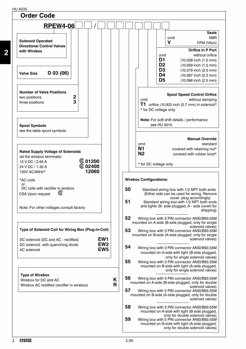
p-Q Characteristics Measured at � = 156 SUS (32 mm2/s) and t = 104 °F (40 °C)
�p-Q Characteristics Measured at � = 156 SUS (32 mm2/s) and t = 104 °F (40 °C)
Pressure drop �p related to flow rate.
Pre
ssur
edr
op�
pin
PS
I(ba
r)
Flow Q in GPM (L/min)
P-A P-B A-T B-T P-TZ11 2 2 3 3C11 5 5 5 6 3H11 2 2 2 3 3P11 1 1 3 3Y11 2 2 2 2L21 2 2 3 3B11 2 2 3 3Z21 2 3F11 1 2 3 3R11 2 2 3 3R21 2 2 3 3A51 2 2P51 1 3Y51 2 2C51 2 3 4Z51 2 3H51 2 3F51 2 3X11 2 2 3 3N11 2 2 3 3J15 2 2 3 3J75 2 2
Ope
ratin
gpr
essu
rep
inP
SI(
bar)
Flow Q in GPM (L/min)
DCZ11 1C11 6H11 3P11 1Y11 2L21 5B11 8J15 1Z21 1
DCH51 7F51 7X11 3N11 7X25 10
DCJ75 9F11 5R11 3R21 4A51 5P51 1Y51 2C51 6
Z51 1
AC AC ACZ51 12 Z11 12 J15 11Y11 12 C11 13 R21 15Y51 12 X11 17 R11 17C51 13 P11 11H11 14 L21 14H51 14 F11 14B11 12 F51 14N11 12 A51 16P51 11 J75 16
Flow Q in GPM (L/min)O
pera
ting
pres
sure
pin
PS
I(ba
r)
11
121613
15
14
17
1617
14 15
1
92
3
5
10
57
10
46
678
8
AC characteristics DC characteristics
2.09
2
5
HU 4035
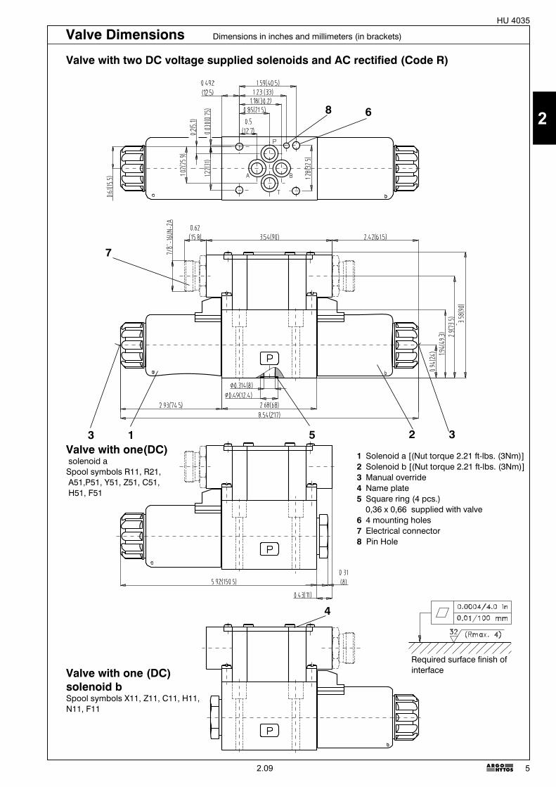
Valve Dimensions Dimensions in inches and millimeters (in brackets)
Required surface finish ofinterface
Valve with one(DC)solenoid aSpool symbols R11, R21,A51,P51, Y51, Z51, C51,H51, F51
Valve with one (DC)solenoid bSpool symbols X11, Z11, C11, H11,N11, F11
1 Solenoid a [(Nut torque 2.21 ft-lbs. (3Nm)]2 Solenoid b [(Nut torque 2.21 ft-lbs. (3Nm)]3 Manual override4 Name plate5 Square ring (4 pcs.)
0,36 x 0,66 supplied with valve6 4 mounting holes7 Electrical connector8 Pin Hole
2 35
7
4
3 1
68
Valve with two DC voltage supplied solenoids and AC rectified (Code R)
2.09
2
6
HU 4035
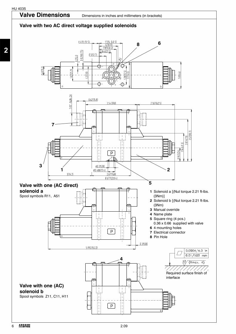
Valve with one (AC direct)solenoid aSpool symbols R11, A51
1 Solenoid a [(Nut torque 2.21 ft-lbs.(3Nm)]
2 Solenoid b [(Nut torque 2.21 ft-lbs.(3Nm)
3 Manual override4 Name plate5 Square ring (4 pcs.)
0.36 x 0.66 supplied with valve6 4 mounting holes7 Electrical connector8 Pin Hole
Valve with one (AC)solenoid bSpool symbols Z11, C11, H11
2
7
1
5
4
6
3
8
Required surface finish ofinterface
Valve Dimensions Dimensions in inches and millimeters (in brackets)
Valve with two AC direct voltage supplied solenoids
2.09
2
7
HU 4035
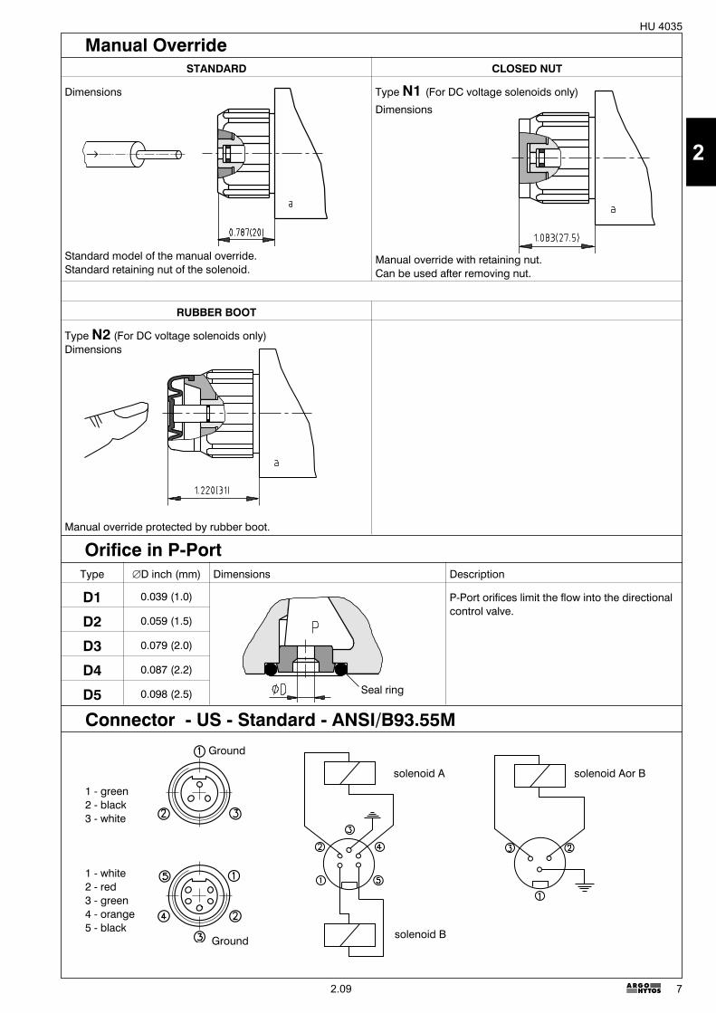
Manual OverrideSTANDARD CLOSED NUT
Dimensions
Standard model of the manual override.Standard retaining nut of the solenoid.
Type N1 (For DC voltage solenoids only)
Dimensions
Manual override with retaining nut.Can be used after removing nut.
RUBBER BOOT
Type N2 (For DC voltage solenoids only)Dimensions
Manual override protected by rubber boot.
Type �D inch (mm) Dimensions Description
D1 0.039 (1.0) P-Port orifices limit the flow into the directionalcontrol valve.
D2 0.059 (1.5)
D3 0.079 (2.0)
D4 0.087 (2.2)
D5 0.098 (2.5)
Orifice in P-Port
Seal ring
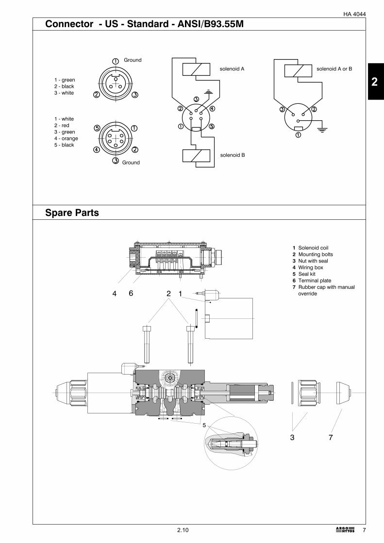
1 - green2 - black3 - white
1 - white2 - red3 - green4 - orange5 - black
solenoid A
solenoid B
solenoid Aor B
Ground
Ground
Connector - US - Standard - ANSI/B93.55M
2.09
2
8
HU 4035
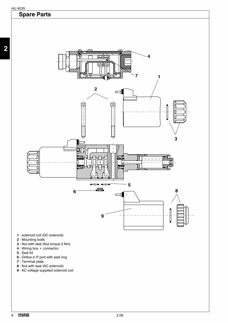
1 - solenoid coil (DC solenoid)2 - Mounting bolts3 - Nut with seal (Nut torque 3 Nm)4 - Wiring box + connector5 - Seal kit6 - Orifice in P port with seal ring7 - Terminal plate8 - Nut with seal (AC solenoid)9 - AC voltage supplied solenoid coil
1
3
2
4
56
7
8
9
Spare Parts
2.09
2
9
HU 4035
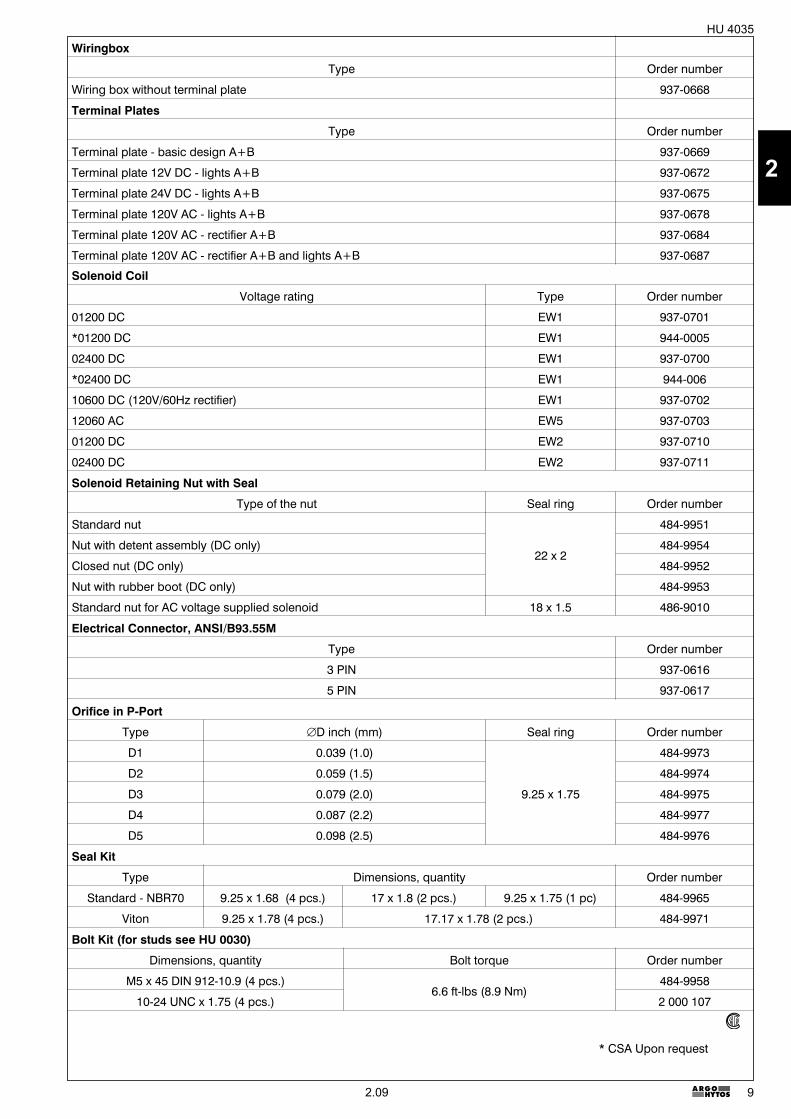
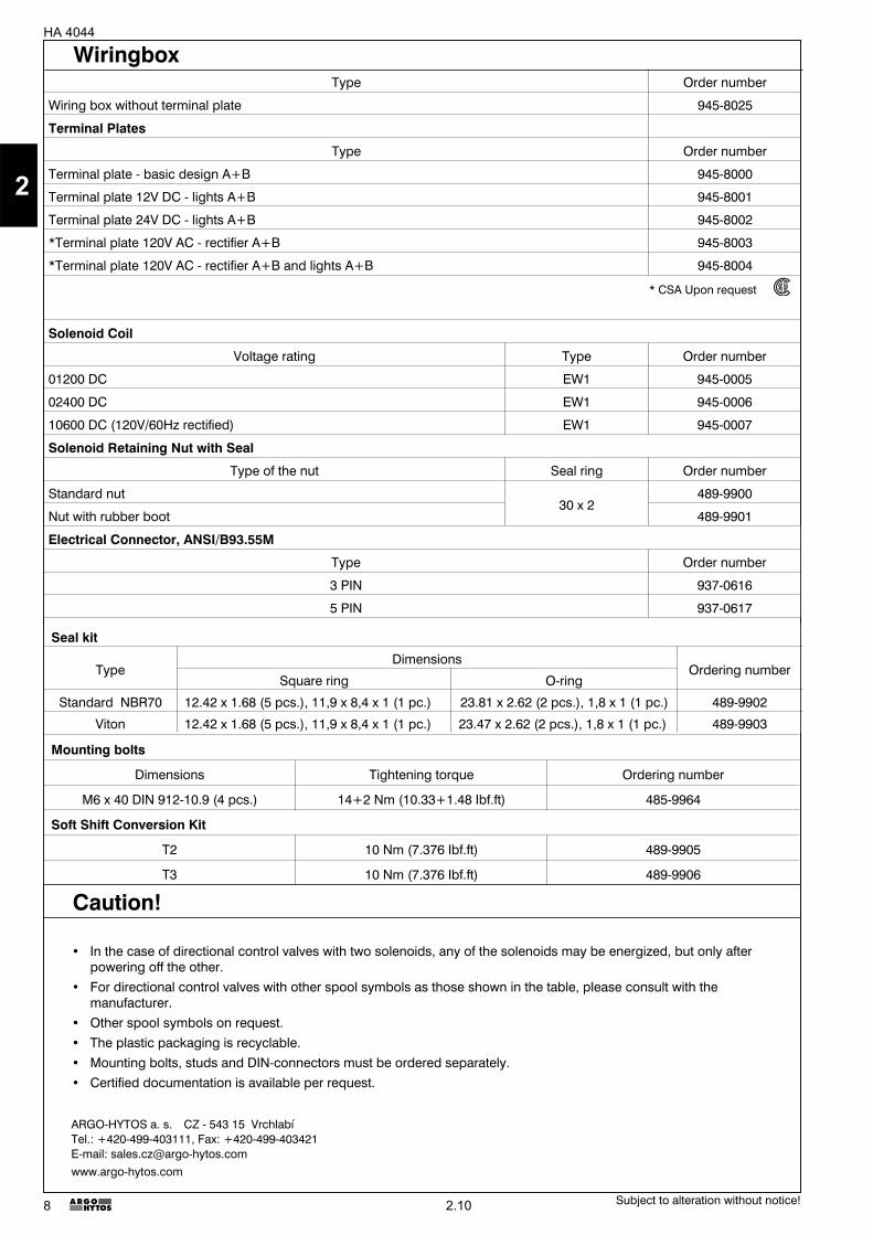
Wiringbox
Type Order number
Wiring box without terminal plate 937-0668
Terminal Plates
Type Order number
Terminal plate - basic design A+B 937-0669
Terminal plate 12V DC - lights A+B 937-0672
Terminal plate 24V DC - lights A+B 937-0675
Terminal plate 120V AC - lights A+B 937-0678
Terminal plate 120V AC - rectifier A+B 937-0684
Terminal plate 120V AC - rectifier A+B and lights A+B 937-0687
* CSA Upon request
Solenoid Coil
Voltage rating Type Order number
01200 DC EW1 937-0701
*01200 DC EW1 944-0005
02400 DC EW1 937-0700
*02400 DC EW1 944-006
10600 DC (120V/60Hz rectifier) EW1 937-0702
12060 AC EW5 937-0703
01200 DC EW2 937-0710
02400 DC EW2 937-0711
Solenoid Retaining Nut with Seal
Type of the nut Seal ring Order number
Standard nut
22 x 2
484-9951
Nut with detent assembly (DC only) 484-9954
Closed nut (DC only) 484-9952
Nut with rubber boot (DC only) 484-9953
Standard nut for AC voltage supplied solenoid 18 x 1.5 486-9010
Electrical Connector, ANSI/B93.55M
Type Order number
3 PIN 937-0616
5 PIN 937-0617
Orifice in P-Port
Type �D inch (mm) Seal ring Order number
D1 0.039 (1.0)
9.25 x 1.75
484-9973
D2 0.059 (1.5) 484-9974
D3 0.079 (2.0) 484-9975
D4 0.087 (2.2) 484-9977
D5 0.098 (2.5) 484-9976
Seal Kit
Type Dimensions, quantity Order number
Standard - NBR70 9.25 x 1.68 (4 pcs.) 17 x 1.8 (2 pcs.) 9.25 x 1.75 (1 pc) 484-9965
Viton 9.25 x 1.78 (4 pcs.) 17.17 x 1.78 (2 pcs.) 484-9971
Bolt Kit (for studs see HU 0030)
Dimensions, quantity Bolt torque Order number
M5 x 45 DIN 912-10.9 (4 pcs.)6.6 ft-lbs (8.9 Nm)
484-9958
10-24 UNC x 1.75 (4 pcs.) 2 000 107
2.09
2
10
HU 4035
� For applications outside the given parameters, please consult us.� With spool symbols A51 and J75 for pressures exceeding 2300 PSI (160 bar), the T-port must be connected
directly to the tank.� For directional control valves with two solenoids, one solenoids must be without power before the other solenoid
can be powered charged. Switching time for directional valves with detent assembly (impulse control) should not beshorter than 60 ms. With directional valves with cushioned spool shifting, the switching time must correspondwith the shifting time.
� Other spool symbols on request.� The plastic packaging foil is recyclable.� Mounting bolts, studs and DIN-connectors must be ordered separately.� Certified documentation is available per request.
Caution!
Subject to alteration without notice!
ARGO-HYTOS a. s. CZ - 543 15 VrchlabíTel.: +420-499-403111, Fax: +420-499-403421E-mail: [email protected]
2.09
2
1
� 4/3-, 4/2- and 3/2-way directional control valves
� Dual frequency solenoids, AC voltage 50/60 Hz
� Wet pin core tubes
� Push button manual override
� With soft shift option
� Installation dimensions to DIN 24 340,ISO 4401, NFPA T3.5.1M R1 and ANSI B 93.7 D 05
� Subplates see data sheet HU 0002
� CSA Upon request
9 8 2 6 7 3 8 9
4 1 5 4
HA 404402/2006
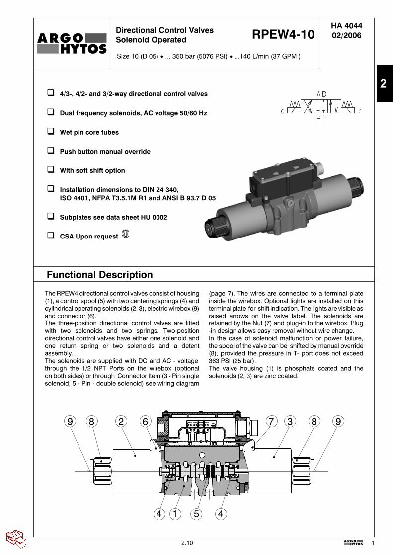
Size 10 (D 05) � ... 350 bar (5076 PSI) � ...140 L/min (37 GPM )
Directional Control ValvesSolenoid Operated RPEW4-10
The RPEW4 directional control valves consist of housing(1), a control spool (5) with two centering springs (4) andcylindrical operating solenoids (2, 3), electric wirebox (9)and connector (6).The three-position directional control valves are fittedwith two solenoids and two springs. Two-positiondirectional control valves have either one solenoid andone return spring or two solenoids and a detentassembly.The solenoids are supplied with DC and AC - voltagethrough the 1/2 NPT Ports on the wirebox (optionalon both sides) or through Connector Item (3 - Pin singlesolenoid, 5 - Pin - double solenoid) see wiring diagram
(page 7). The wires are connected to a terminal plateinside the wirebox. Optional lights are installed on thisterminal plate for shift indication. The lights are visible asraised arrows on the valve label. The solenoids areretained by the Nut (7) and plug-in to the wirebox. Plug-in design allows easy removal without wire change.In the case of solenoid malfunction or power failure,the spool of the valve can be shifted by manual override(8), provided the pressure in T- port does not exceed363 PSI (25 bar).The valve housing (1) is phosphate coated and thesolenoids (2, 3) are zinc coated.
Functional Description
2.10
2
2
HA 4044
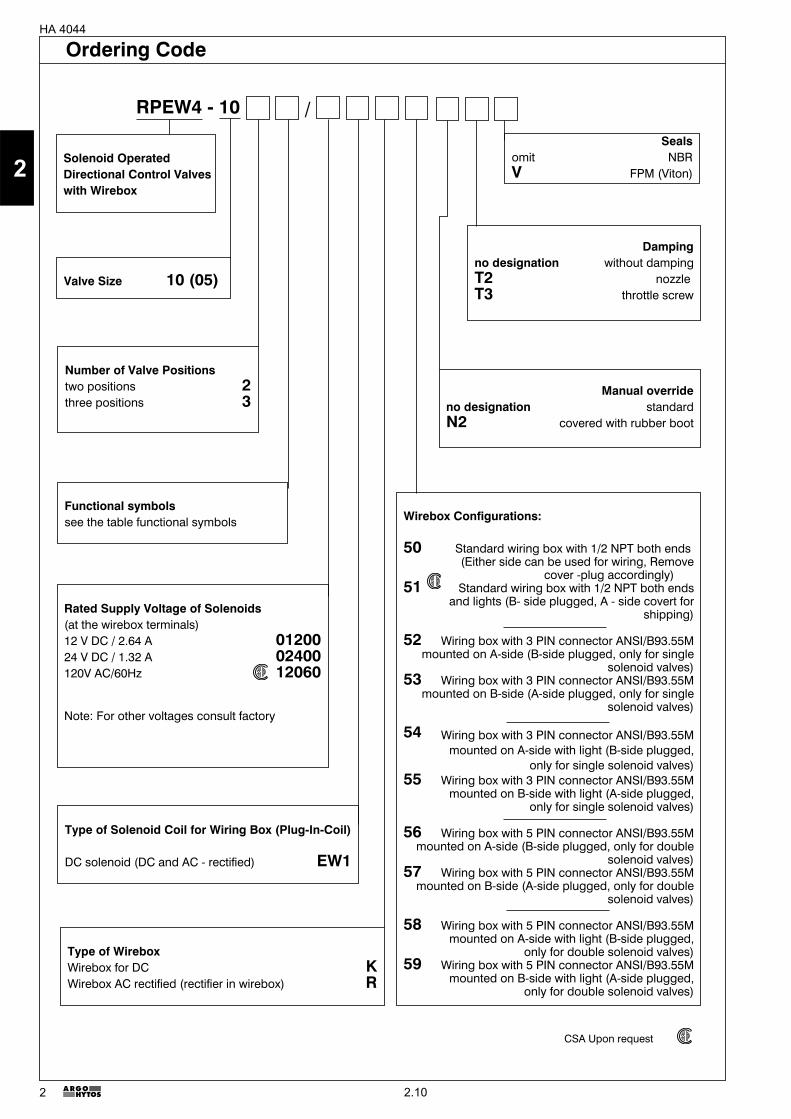
Ordering Code
Functional symbolssee the table functional symbols
Valve Size 10 (05)
Solenoid OperatedDirectional Control Valveswith Wirebox
Number of Valve Positionstwo positions 2three positions 3
Rated Supply Voltage of Solenoids(at the wirebox terminals)12 V DC / 2.64 A 0120024 V DC / 1.32 A 02400120V AC/60Hz 12060
Note: For other voltages consult factory
Type of Solenoid Coil for Wiring Box (Plug-In-Coil)
DC solenoid (DC and AC - rectified) EW1
Sealsomit NBRV FPM (Viton)
Wirebox Configurations:
50 Standard wiring box with 1/2 NPT both ends(Either side can be used for wiring, Remove
cover -plug accordingly)51 Standard wiring box with 1/2 NPT both ends
and lights (B- side plugged, A - side covert forshipping)
52 Wiring box with 3 PIN connector ANSI/B93.55Mmounted on A-side (B-side plugged, only for single
solenoid valves)53 Wiring box with 3 PIN connector ANSI/B93.55M
mounted on B-side (A-side plugged, only for singlesolenoid valves)
54 Wiring box with 3 PIN connector ANSI/B93.55Mmounted on A-side with light (B-side plugged,
only for single solenoid valves)55 Wiring box with 3 PIN connector ANSI/B93.55M
mounted on B-side with light (A-side plugged,only for single solenoid valves)
56 Wiring box with 5 PIN connector ANSI/B93.55Mmounted on A-side (B-side plugged, only for double
solenoid valves)57 Wiring box with 5 PIN connector ANSI/B93.55M
mounted on B-side (A-side plugged, only for doublesolenoid valves)
58 Wiring box with 5 PIN connector ANSI/B93.55Mmounted on A-side with light (B-side plugged,
only for double solenoid valves)59 Wiring box with 5 PIN connector ANSI/B93.55M
mounted on B-side with light (A-side plugged,only for double solenoid valves)
Type of WireboxWirebox for DC KWirebox AC rectified (rectifier in wirebox) R
RPEW4 - 10
Dampingno designation without dampingT2 nozzleT3 throttle screw
Manual overrideno designation standardN2 covered with rubber boot
/
CSA Upon request
2.10
2
3
HA 4044
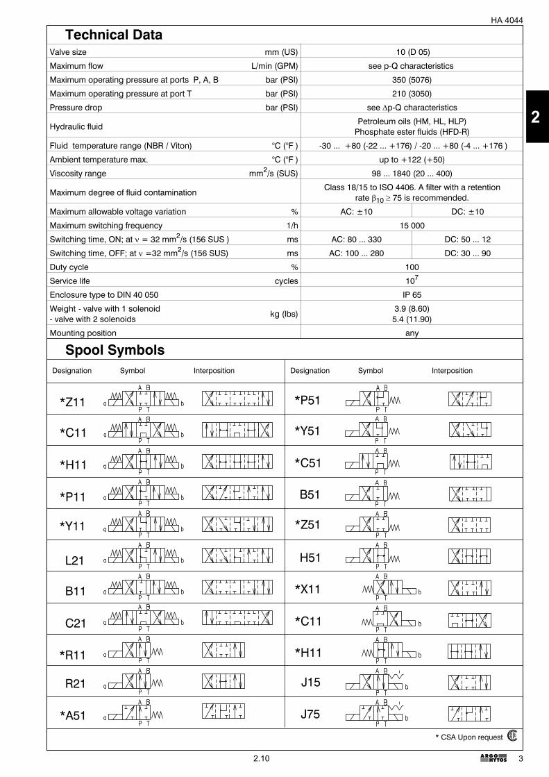
Designation Symbol Interposition Designation Symbol Interposition
*Z11
*H11
*C11
*P11
*Y11
L21
C21
B11
*R11
R21
*A51
H51
*H11
*P51
*C51
*Y51
B51
*Z51
*C11
*X11
J15
J75
Technical DataValve size mm (US) 10 (D 05)
Maximum flow L/min (GPM) see p-Q characteristics
Maximum operating pressure at ports P, A, B bar (PSI) 350 (5076)
Maximum operating pressure at port T bar (PSI) 210 (3050)
Pressure drop bar (PSI) see �p-Q characteristics
Hydraulic fluidPetroleum oils (HM, HL, HLP)
Phosphate ester fluids (HFD-R)
Fluid temperature range (NBR / Viton) °C (°F ) -30 ... +80 (-22 ... +176) / -20 ... +80 (-4 ... +176 )
Ambient temperature max. °C (°F ) up to +122 (+50)
Viscosity range mm2/s (SUS) 98 ... 1840 (20 ... 400)
Maximum degree of fluid contaminationClass 18/15 to ISO 4406. A filter with a retention
rate 10 � 75 is recommended.
Maximum allowable voltage variation % AC: ±10 DC: ±10
Maximum switching frequency 1/h 15 000
Switching time, ON; at � = 32 mm2/s (156 SUS ) ms AC: 80 ... 330 DC: 50 ... 12
Switching time, OFF; at � =32 mm2/s (156 SUS) ms AC: 100 ... 280 DC: 30 ... 90
Duty cycle % 100
Service life cycles 107
Enclosure type to DIN 40 050 IP 65
Weight - valve with 1 solenoid- valve with 2 solenoids
kg (lbs)3.9 (8.60)5.4 (11.90)
Mounting position any
Spool Symbols
* CSA Upon request
2.10
2
4
HA 4044
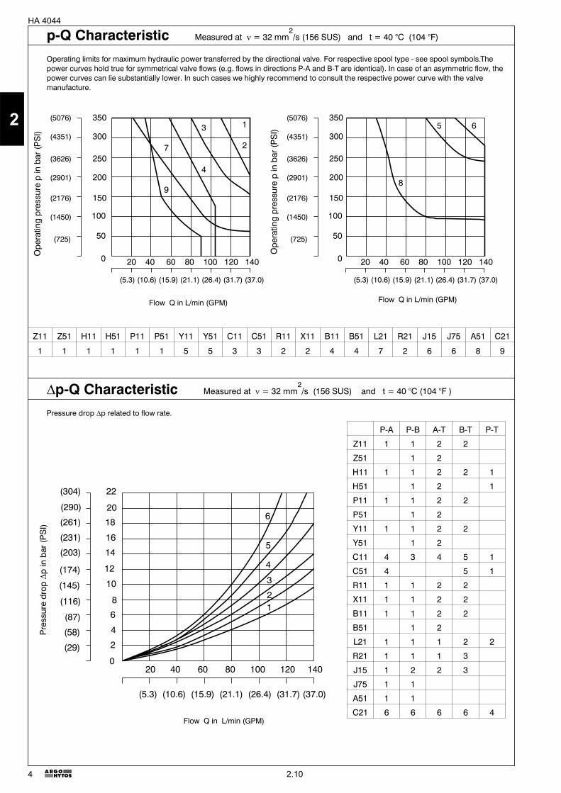
P-A P-B A-T B-T P-T
Z11 1 1 2 2
Z51 1 2
H11 1 1 2 2 1
H51 1 2 1
P11 1 1 2 2
P51 1 2
Y11 1 1 2 2
Y51 1 2
C11 4 3 4 5 1
C51 4 5 1
R11 1 1 2 2
X11 1 1 2 2
B11 1 1 2 2
B51 1 2
L21 1 1 1 2 2
R21 1 1 1 3
J15 1 2 2 3
J75 1 1
A51 1 1
C21 6 6 6 6 4
(725)
(1450)
(2176)
(2901)
(3626)
(4351)
(5076)
100
150
200
250
300
350
50
0
(725)
(1450)
(2176)
(2901)
(3626)
(4351)
(5076)
100
150
200
250
300
350
50
020 40 60 80 100 120 140
(5.3) (10.6) (15.9) (21.1) (26.4) (31.7) (37.0)
20 40 60 80 100 120 140
(5.3) (10.6) (15.9) (21.1) (26.4) (31.7) (37.0)
1
27
9
3
4
5 6
8
(145)
(174)
(203)
(231)
(261)
(290)
(304)
12
14
16
18
20
22
20 40 60 80 100 120 140
(5.3) (10.6) (15.9) (21.1) (26.4) (31.7) (37.0)
0
2
4
6
8
10
(29)
(58)
(87)
(116)
6
5
4
3
21
Flow Q in L/min (GPM)
Flow Q in L/min (GPM)
Pre
ssur
edr
op�
pin
bar(
PS
I)
Z11 Z51 H11 H51 P11 P51 Y11 Y51 C11 C51 R11 X11 B11 B51 L21 R21 J15 J75 A51 C21
1 1 1 1 1 1 5 5 3 3 2 2 4 4 7 2 6 6 8 9
p-Q Characteristic Measured at � = 32 mm2/s (156 SUS) and t = 40 °C (104 °F)
Operating limits for maximum hydraulic power transferred by the directional valve. For respective spool type - see spool symbols.Thepower curves hold true for symmetrical valve flows (e.g. flows in directions P-A and B-T are identical). In case of an asymmetric flow, thepower curves can lie substantially lower. In such cases we highly recommend to consult the respective power curve with the valvemanufacture.
�p-Q Characteristic Measured at � = 32 mm2/s (156 SUS) and t = 40 °C (104 °F )
Pressure drop �p related to flow rate.
Flow Q in L/min (GPM)
Ope
ratin
gpr
essu
rep
inba
r(P
SI)
Ope
ratin
gpr
essu
rep
inba
r(P
SI)
2.10
2
53 2
7
3
6
9
4
15.45 (0.608)
106 (4.173)
62(2
.440
)
35(1
.377
)
hexagon 5 A/F
70(2
.756
)
118.
5(4
.665
)
122
(4.8
03)
96(3
.78)
59.9 (2.358)
~68.2 (2.685)
46 (1.811)
7/8"
-16U
N-2
A
16 (0.63)
6.6 (0.26)
10.5 (0.413)
30(1
.181
)
8.5 (0.334)
((220.5) (8.681))
3.2 (0.126)
16.7 (0.657)
27 (1.063)
50.8 (2)
54 (2.126)
13.5
(0.5
31)
24.6
(0.9
69)
39.7
(1.5
63)
46(1
.811
)
�11 (0.433)
106 (4.173) 106 (4.173)
hexagon 10 A/F
hexagon 36 A/F
�
106 (4.173) 106 (4.173)
15.45 (0.608)
106 (4.173)
((318) (12.519))
hexagon 32 A/F
106 (4.173)
8.5 (0.334)
((220.5) (8.681))
37.3 (1.468)
ab
ab
ab
a
b
8
5
HA 4044
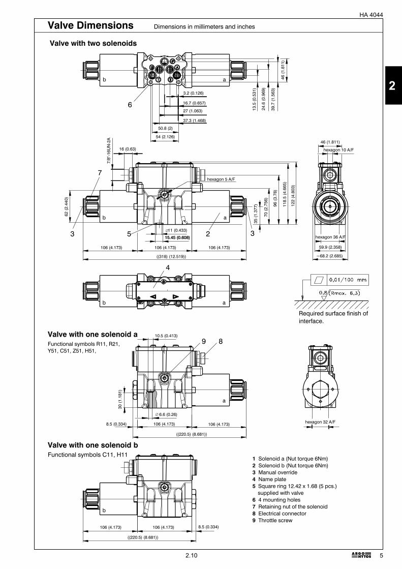
Valve with one solenoid aFunctional symbols R11, R21,Y51, C51, Z51, H51,
Valve with one solenoid bFunctional symbols C11, H11
1 Solenoid a (Nut torque 6Nm)2 Solenoid b (Nut torque 6Nm)3 Manual override4 Name plate5 Square ring 12.42 x 1.68 (5 pcs.)
supplied with valve6 4 mounting holes7 Retaining nut of the solenoid8 Electrical connector9 Throttle screw
Valve with two solenoids
Required surface finish ofinterface.
Valve Dimensions Dimensions in millimeters and inches
2.10
2
6
HA 4044
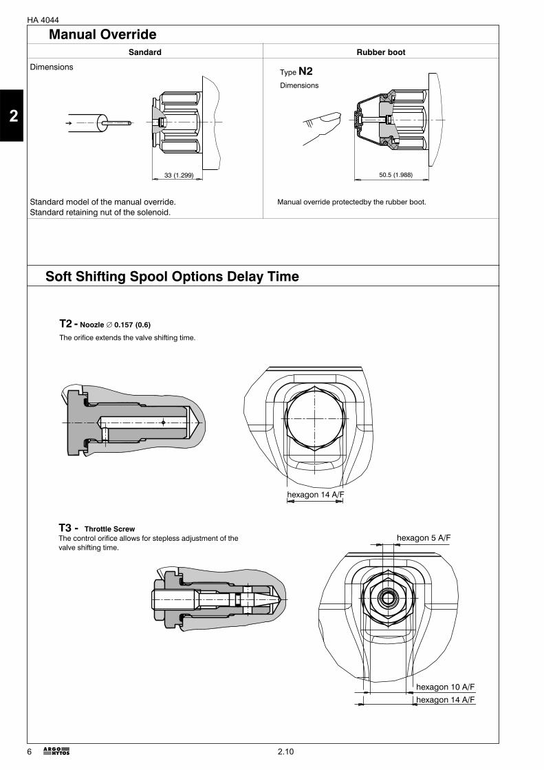
Manual OverrideSandard Rubber boot
Dimensions
Standard model of the manual override.Standard retaining nut of the solenoid.
33 1.299( ) 50.5 1.988( )
Manual override protectedby the rubber boot.
Type N2Dimensions
hexagon 14 A/F
hexagon 14 A/Fhexagon 10 A/F
hexagon 5 A/F
T2 - Noozle � 0.157 (0.6)
The orifice extends the valve shifting time.
T3 - Throttle ScrewThe control orifice allows for stepless adjustment of thevalve shifting time.
Soft Shifting Spool Options Delay Time
2.10
2
7
HA 4044
1 Solenoid coil2 Mounting bolts3 Nut with seal4 Wiring box5 Seal kit6 Terminal plate7 Rubber cap with manual
override
5
1
3 7
4 26
Connector - US - Standard - ANSI/B93.55M
1 - green2 - black3 - white
1 - white2 - red3 - green4 - orange5 - black
solenoid A
solenoid B
solenoid A or B
Ground
Ground
Spare Parts
2.10
2
8
HA 4044
Solenoid Coil
Voltage rating Type Order number
01200 DC EW1 945-0005
02400 DC EW1 945-0006
10600 DC (120V/60Hz rectified) EW1 945-0007
Solenoid Retaining Nut with Seal
Type of the nut Seal ring Order number
Standard nut30 x 2
489-9900
Nut with rubber boot 489-9901
Electrical Connector, ANSI/B93.55M
Type Order number
3 PIN 937-0616
5 PIN 937-0617
Seal kit
TypeDimensions
Ordering numberSquare ring O-ring
Standard NBR70 12.42 x 1.68 (5 pcs.), 11,9 x 8,4 x 1 (1 pc.) 23.81 x 2.62 (2 pcs.), 1,8 x 1 (1 pc.) 489-9902
Viton 12.42 x 1.68 (5 pcs.), 11,9 x 8,4 x 1 (1 pc.) 23.47 x 2.62 (2 pcs.), 1,8 x 1 (1 pc.) 489-9903
Mounting bolts
Dimensions Tightening torque Ordering number
M6 x 40 DIN 912-10.9 (4 pcs.) 14+2 Nm (10.33+1.48 Ibf.ft) 485-9964
Soft Shift Conversion Kit
T2 10 Nm (7.376 Ibf.ft) 489-9905
T3 10 Nm (7.376 Ibf.ft) 489-9906
� In the case of directional control valves with two solenoids, any of the solenoids may be energized, but only afterpowering off the other.
� For directional control valves with other spool symbols as those shown in the table, please consult with themanufacturer.
� Other spool symbols on request.� The plastic packaging is recyclable.� Mounting bolts, studs and DIN-connectors must be ordered separately.� Certified documentation is available per request.
Type Order number
Wiring box without terminal plate 945-8025
Terminal Plates
Type Order number
Terminal plate - basic design A+B 945-8000
Terminal plate 12V DC - lights A+B 945-8001
Terminal plate 24V DC - lights A+B 945-8002
*Terminal plate 120V AC - rectifier A+B 945-8003
*Terminal plate 120V AC - rectifier A+B and lights A+B 945-8004
Wiringbox
Caution!
Subject to alteration without notice!
ARGO-HYTOS a. s. CZ - 543 15 VrchlabíTel.: +420-499-403111, Fax: +420-499-403421E-mail: [email protected]
* CSA Upon request
2.10
2


![BR Class 156 Pack for RailWorks [v1.0.0] BR CLASS 156 DMU](https://img.pdfslide.us/doc/110x75/61e00bb48cb0f3006830a70a/br-class-156-pack-for-railworks-v100-br-class-156-dmu.jpg)