Embed Size (px)
Citation preview

Argent Data Systems
Tracker3 Family
User’s Manual
Revised 1-3-2014
Argent Data Systems, Inc. PO Box 579 Santa Maria, CA 93456-0579 USA (800) 274-4076 / +1 805 619-4515 Fax (866) 302-6890 www.argentdata.com Copyright © 2007-2013 Argent Data Systems, Inc. All Rights Reserved APRS® is a registered trademark of Bob Bruninga, WB4APR
FCC Part 15 Notice
This device complies with Part 15 of the FCC Rules Operation is subject to the following two conditions: this device may not cause harmful
interference, and (2) this device must accept any interference
received, including interference that may cause undesired operation. This equipment has been tested and found to comply with the limits for a Class B Digital Device, pursuant to part 15 of the FCC Rules.
These limits are designed to provide reasonable protection against harmful interference in a residential installation. This equipment
generates, uses, and can radiate radio frequency energy and, if not installed and used in accordance with the instructions, may cause
harmful interference to radio communication. However, there is no grantee that interference will not occur in a particular installation. If
this equipment does cause harmful interference to radio or television reception, which can be determined by tuning the equipment off and
on, the user is encouraged to try to correct the interference by one or more of the following measures:
• Reorient or relocate the receiving antenna. • Increase the separation between the equipment and receiver.
• Connect the equipment into an outlet on a circuit different from that to which the receiver is connected.
• Consult the dealer or an experienced radio/TV technician for
help.
CE Declaration
This device complies with the essential protection requirements of the European Parliament and of the Council Directive 2004/108/EC on the
approximation of the laws of the Member States relating to electromagnetic compatibility. Assessment of compliance of the product with the requirements relating to electromagnetic compatibility
was based on the following standards:
EN 55022 : 2006 EN 61000 - 3 - 2 : 2006
EN 61000 - 3 - 3 : 1995+A1 : 2001+A2 : 2005
EN 55024 : 1998 + A1 : 2001+ A2 : 2003
EN 61000-4-2 /-3 /-4 /-5 /-6 /-11
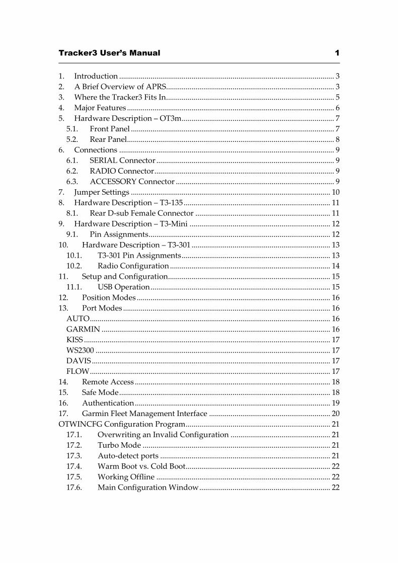
Tracker3 User’s Manual 1
1. Introduction .............................................................................................................. 3 2. A Brief Overview of APRS...................................................................................... 3 3. Where the Tracker3 Fits In...................................................................................... 5 4. Major Features .......................................................................................................... 6 5. Hardware Description – OT3m.............................................................................. 7
5.1. Front Panel ........................................................................................................ 7 5.2. Rear Panel.......................................................................................................... 8
6. Connections .............................................................................................................. 9 6.1. SERIAL Connector ........................................................................................... 9 6.2. RADIO Connector............................................................................................ 9 6.3. ACCESSORY Connector ................................................................................. 9
7. Jumper Settings ...................................................................................................... 10 8. Hardware Description – T3-135........................................................................... 11
8.1. Rear D-sub Female Connector ..................................................................... 11 9. Hardware Description – T3-Mini ........................................................................ 12
9.1. Pin Assignments............................................................................................. 12 10. Hardware Description – T3-301 ....................................................................... 13
10.1. T3-301 Pin Assignments............................................................................ 13 10.2. Radio Configuration .................................................................................. 14
11. Setup and Configuration................................................................................... 15 11.1. USB Operation............................................................................................ 15
12. Position Modes ................................................................................................... 16 13. Port Modes .......................................................................................................... 16
AUTO........................................................................................................................... 16 GARMIN ..................................................................................................................... 16 KISS .............................................................................................................................. 17 WS2300 ........................................................................................................................ 17 DAVIS .......................................................................................................................... 17 FLOW........................................................................................................................... 17
14. Remote Access .................................................................................................... 18 15. Safe Mode............................................................................................................ 18 16. Authentication.................................................................................................... 19 17. Garmin Fleet Management Interface .............................................................. 20 OTWINCFG Configuration Program.......................................................................... 21
17.1. Overwriting an Invalid Configuration ................................................... 21 17.2. Turbo Mode ................................................................................................ 21 17.3. Auto-detect ports ....................................................................................... 21 17.4. Warm Boot vs. Cold Boot.......................................................................... 22 17.5. Working Offline ......................................................................................... 22 17.6. Main Configuration Window................................................................... 22
Tracker3 User’s Manual 2
17.7. Configuration Profiles ............................................................................... 23 17.8. Loading and Saving Settings.................................................................... 23 17.9. Basic Configuration Options .................................................................... 23 17.10. Tuning and Diagnostics ............................................................................ 29 17.11. Access List ................................................................................................... 30 17.12. Profile Switching ........................................................................................ 30 17.13. Digipeater Settings..................................................................................... 31 17.14. Script Editor ................................................................................................ 32
18. Command Reference ......................................................................................... 33 19. Telemetry............................................................................................................. 45 20. Script System ...................................................................................................... 46
20.1. Script Editor ................................................................................................ 46 20.2. Script Commands....................................................................................... 48 20.3. Counters ...................................................................................................... 50
21. UI-View32 Setup ................................................................................................ 52
Tracker3 User’s Manual 3
1. Introduction
The Tracker3 family includes the stand-alone OT3m model, the T3-135 internal
board for the Alinco DR-135T, the embeddable T3-Mini board, and the T3-301
with integrated 5-watt transceiver. All of these models share the same software
features, with minor differences. This manual covers all Tracker3 variations.
The Tracker3 is a packet radio interface focused on APRS™ applications,
including position reporting, messaging, and telemetry. It replaces the older
Tracker2 and features a much faster, 32-bit processor, USB support, more RAM,
and more room for expansion.
Firmware updates and enhancements are published frequently, so check the
website at http://www.argentdata.com to make sure you have the latest firmware
and documentation. The Wiki site at http://wiki.argentdata.com also has in-
depth technical information and user-contributed tips and tricks.
2. A Brief Overview of APRS
To understand the Tracker3 and how it can be used, it is important to first
understand exactly what APRS is.
APRS stands for Automatic Packet Reporting System. The name is a trademark
of its creator, Bob Bruninga, WB4APR. What the name refers to can be a subject
of considerable confusion to newcomers.
Primarily, APRS is a communications protocol. It defines how data (including
station and map object positions, weather information, radio direction finding
readings, text messages, and telemetry) can be communicated among packet
radio stations.
APRS can also refer to the network that carries this information. Throughout the
United States, Europe, and several other countries, a network of digital repeaters
(‘digipeaters’), usually on a common nationwide frequency, provides a transport
for APRS packets. Most APRS stations operate on one of these common
channels, but not all.
The APRS Internet System (APRS-IS) is an Internet-based adjunct to the radio
network. Internet gateways (IGates), often simply home PCs with an Internet

Tracker3 User’s Manual 4
connection and a radio, pass traffic from the radio network to a shared,
worldwide APRS stream. Many IGates will pass at least text message traffic, and
sometimes other data, from the Internet back to the radio network. In this way,
text messages can be passed from one station to another even when a digipeater
path between the two doesn’t exist or isn’t reliable.
The name APRS is also sometimes used to refer to WB4APR’s original MS-DOS
APRS mapping program, but this is now properly called APRSdos. Numerous
other mapping and messaging programs exist, using either the APRS radio
network, the APRS-IS, or both. Some of these programs can function as IGates as
well.
Connected to the worldwide APRS-IS stream are a number of database services.
These systems (aprs.fi and openaprs.net are two of the most popular) process
and store all APRS traffic that finds its way to an IGate anywhere in the world,
and most provide maps, weather displays, and telemetry graphs based on this
traffic. This allows anyone with Internet access to monitor APRS data without
needing radio equipment of their own or special software.
Getting data to a web-connected database isn’t the only thing APRS is good for,
of course. Depending on network coverage and load, it’s possible to
communicate over a range of hundreds of miles using the radio network alone.
However, being a shared network, reliability decreases with each added
digipeater hop. APRS is most reliable at the local level, and it’s rarely advisable
to use more than two or three digipeater hops. Often, a single hop is adequate
for local coverage.
The APRS protocol, hardware, and software can be used independently of the
national networks, as well. Local or temporary networks may be set up to cover
special events or to fill the needs of a particular organization. Some uses may not
require digipeaters at all – high altitude balloons, for example, often use APRS to
transmit position and telemetry data on a dedicated frequency directly to the
chase teams.
Mobile use of APRS can take a number of different forms. The simplest mobile
APRS setup is a transmit-only tracker connected to a radio and GPS receiver.
These trackers generally have no receive capability, other than to check that the
channel is clear before transmitting. They allow the vehicle to be tracked by
others, but can’t receive messages or positions.
Tracker3 User’s Manual 5
Another option is an APRS-capable radio, like those sold by Kenwood and
Yaesu. These radios have a text display, but require a mapping GPS receiver to
display the positions of other stations graphically.
An ordinary radio with a TNC can be used in conjunction with a laptop
computer or PDA to provide full APRS functionality, including mapping and
messaging, although this is usually the most expensive option and may not be
practical to operate while driving.
3. Where the Tracker3 Fits In
The Tracker3 has the capability to fill a number of roles in the APRS system. As
the name implies, it’s a tracker – it can format and transmit position data from a
GPS receiver for transmission over APRS. It also receives and decodes positions
from other APRS stations.
When it receives a position for a station or map object, the Tracker3 can create a
GPS waypoint for that position. On a mapping GPS receiver, this allows the user
to see the locations of other stations on the map, updated as each new position is
received.
When used with a suitable mapping GPS receiver, the tracker will pick the most
appropriate symbol for the waypoint (including custom APRS symbols if
available), extract the altitude, and insert the status text (often including course
and speed) into the waypoint details. For many applications, this can eliminate
the need for a PC or similar device to act as a display.
Aside from its tracking capabilities, the Tracker3 can also function as a
digipeater. Its remote control capabilities allow it to be reconfigured remotely,
and even through IGates, and its path limiting features let the sysop reduce the
amount of extraneous traffic carried by the network.
In KISS mode, the Tracker3 can also function as part of an IGate, when connected
to a PC with an Internet connection and appropriate software.
With few exceptions, the Tracker3 can perform all of its functions concurrently.
For example, a mountaintop installation could function simultaneously as a
digipeater, weather station, site monitor (reporting voltage and temperature),
and TNC for an IGate.
Tracker3 User’s Manual 6
4. Major Features
APRS Tracker - The Tracker3 is first and foremost a full-featured APRS tracker.
It works with GPS receivers using either the industry-standard NMEA format
($GPRMC, $GPGGA, and $GPGLL sentences) or the proprietary Garmin binary
protocol. In addition to transmitting its own position, it can also decode
incoming positions and plot them as waypoints on the screen of a GPS receiver,
selecting appropriate symbols and setting comment text and other waypoint
details if supported by the receiver.
KISS Mode - The KISS protocol defines an interface between a TNC and its host,
typically a PC. This mode allows the Tracker3 to be used with PC-based APRS
programs like Xastir, WinAPRS, and UI-View32. It can also be used with non-
APRS applications, subject to the limitations of the Tracker3’s transmit and
receive buffers.
Digipeater - A digipeater acts as a simplex digital repeater, receiving packets
and retransmitting them, typically on the same radio channel. The Tracker3’s
digipeater function is designed specifically for APRS use, and supports advanced
features such as WIDEn-N operation, hop count limiting, duplicate elimination,
preemptive digipeating, and multiple aliases.
Weather Station – The Tracker3 can be connected to several models of weather
station, including the Peet Bros. Ultimeter 2000 series, Davis Vantage Pro 2, and
LaCrosse WS-2310 wireless weather station, to provide remote weather
telemetry.
Command Console – While the Tracker3 comes with a Windows-based
configuration program, it can also be configured, tuned, and upgraded through a
traditional console interface with command syntax similar to that of the classic
TNC2 and its clones. Keyboard-to-keyboard QSOs are supported through a
‘converse’ mode as well as APRS messaging commands.
Power Control – The OT3m includes an integrated solid-state relay that may be
used to control an external DC load. Typically, this is used to control power to a
transceiver to conserve power in applications like solar-powered weather
stations; the radio can be automatically powered on just prior to a transmission,
and turned off again when the transmission is complete. The power output can
also be controlled manually through APRS messages.
Tracker3 User’s Manual 7
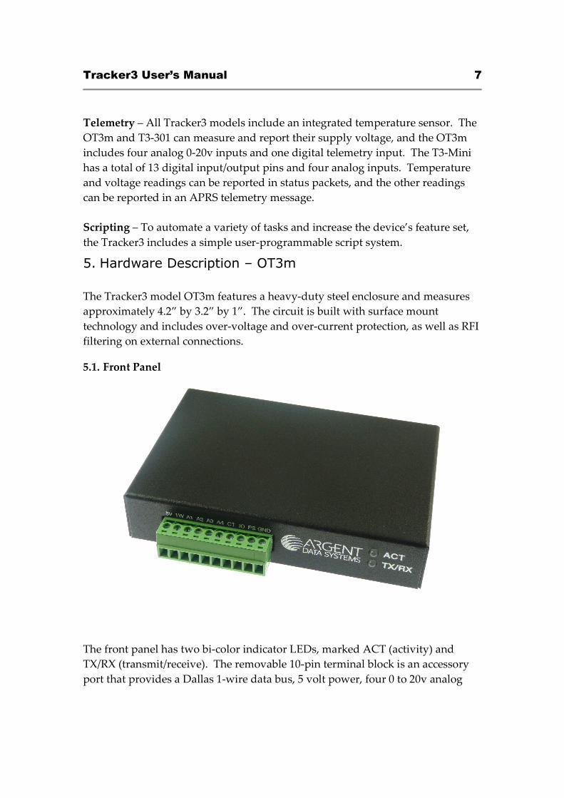
Telemetry – All Tracker3 models include an integrated temperature sensor. The
OT3m and T3-301 can measure and report their supply voltage, and the OT3m
includes four analog 0-20v inputs and one digital telemetry input. The T3-Mini
has a total of 13 digital input/output pins and four analog inputs. Temperature
and voltage readings can be reported in status packets, and the other readings
can be reported in an APRS telemetry message.
Scripting – To automate a variety of tasks and increase the device’s feature set,
the Tracker3 includes a simple user-programmable script system.
5. Hardware Description – OT3m
The Tracker3 model OT3m features a heavy-duty steel enclosure and measures
approximately 4.2” by 3.2” by 1”. The circuit is built with surface mount
technology and includes over-voltage and over-current protection, as well as RFI
filtering on external connections.
5.1. Front Panel
The front panel has two bi-color indicator LEDs, marked ACT (activity) and
TX/RX (transmit/receive). The removable 10-pin terminal block is an accessory
port that provides a Dallas 1-wire data bus, 5 volt power, four 0 to 20v analog
Tracker3 User’s Manual 8
inputs, a counter/transmit trigger input, a digital I/O pin, and a 7-amp solid state
relay output.
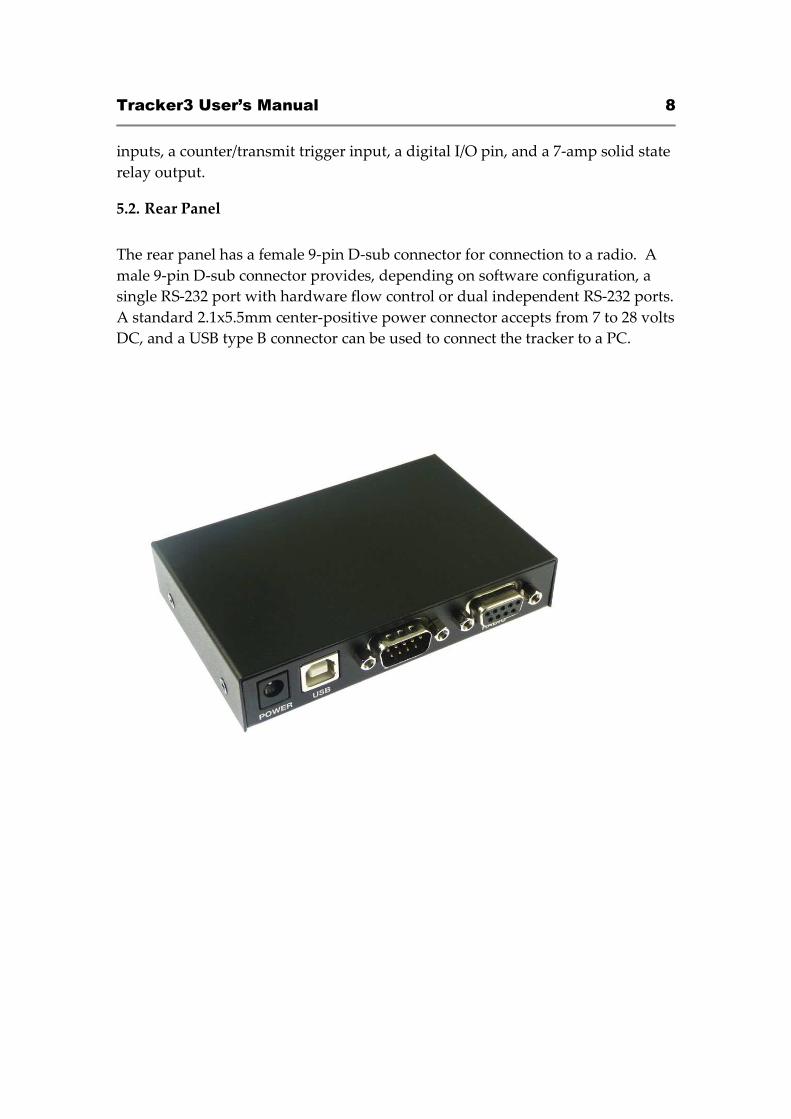
5.2. Rear Panel
The rear panel has a female 9-pin D-sub connector for connection to a radio. A
male 9-pin D-sub connector provides, depending on software configuration, a
single RS-232 port with hardware flow control or dual independent RS-232 ports.
A standard 2.1x5.5mm center-positive power connector accepts from 7 to 28 volts
DC, and a USB type B connector can be used to connect the tracker to a PC.
Tracker3 User’s Manual 9
6. Connections
6.1. SERIAL Connector
2: Data in (port A)
3: Data out (port A)
4: Power output for GPS
5: Ground
7: Data out (port B) or CTS
8: Data in (port B) or RTS
Note: The serial interface is configured as DTE (data terminal equipment) to
allow direct connection to a GPS receiver. Connection to a PC requires a null-
modem cable.
6.2. RADIO Connector
1: Audio out
2: COR / Squelch input
3: PTT out
5: Audio in
6: Ground
7: Power in
8: PTT in
6.3. ACCESSORY Connector
1: +5v output
2: Dallas 1-Wire data bus
3-6: 0-20v analog inputs
7: Counter / TX trigger input
8: Digital I/O line
9: Relay output
10: Ground
Connector is a pluggable 0.150” pitch screw terminal block.
Tracker3 User’s Manual 10
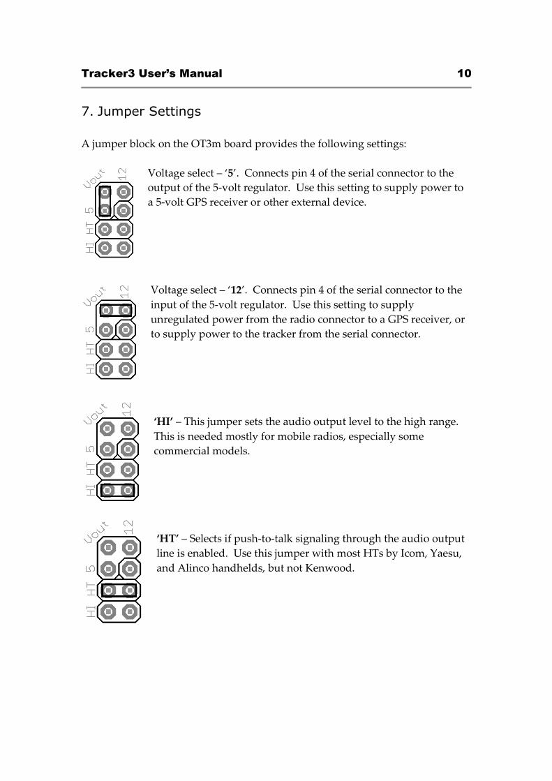
7. Jumper Settings
A jumper block on the OT3m board provides the following settings:
Voltage select – ‘5’. Connects pin 4 of the serial connector to the
output of the 5-volt regulator. Use this setting to supply power to
a 5-volt GPS receiver or other external device.
Voltage select – ‘12’. Connects pin 4 of the serial connector to the
input of the 5-volt regulator. Use this setting to supply
unregulated power from the radio connector to a GPS receiver, or
to supply power to the tracker from the serial connector.
‘HI’ – This jumper sets the audio output level to the high range.
This is needed mostly for mobile radios, especially some
commercial models.
‘HT’ – Selects if push-to-talk signaling through the audio output
line is enabled. Use this jumper with most HTs by Icom, Yaesu,
and Alinco handhelds, but not Kenwood.
Tracker3 User’s Manual 11
8. Hardware Description – T3-135
The Tracker3 model T3-135 is a plug-in board for the Alinco DR-135T. It can also
be used with the DR-235 and DR-435 models.
To install the board, disconnect power to the radio and remove the four screws
holding on the bottom cover plate. A multi-colored cable connects the rear
connector to the radio’s main board. Remove the cable from the radio board,
plug it in to the receptacle on the T3-135 board, and plug the T3-135 board’s cable
into the radio board. The supplied hook and loop fastener can be used to secure
the T3-135 board to the VCO case.
A short USB pigtail cable is also provided with the board. The small end plugs
in to the T3-135 board, and the cable can be routed out of the radio by bending or
cutting the metal tab on the radio’s cover that covers the space above the speaker
jack.
The T3-135 board is active only when the radio is placed in digital mode,
indicated by a square wave icon on the display. When the radio is tuned to a
memory channel that has the digital option set, the tracker will power up
automatically. The tracker must be powered up before it can be configured.
In data mode, the front-panel ‘Data’ jack is used as the tracker’s port B input,
with data in on the tip, +5v power out on the ring, and ground on the sleeve.
This input can be used for weather station or NMEA GPS input. Be sure to check
the polarity of the power output before using it the first time – some earlier DR-
135T radios may have an inverted output. If a complete reset of the radio fails to
correct the problem, contact Alinco customer service.
8.1. Rear D-sub Female Connector
2: Data out (from tracker)
3: Data in (to tracker)
5: Ground
8: 1-Wire data bus
Tracker3 User’s Manual 12
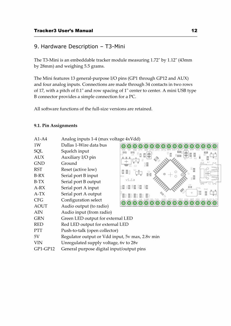
9. Hardware Description – T3-Mini
The T3-Mini is an embeddable tracker module measuring 1.72" by 1.12" (43mm
by 28mm) and weighing 5.5 grams.
The Mini features 13 general-purpose I/O pins (GP1 through GP12 and AUX)
and four analog inputs. Connections are made through 34 contacts in two rows
of 17, with a pitch of 0.1" and row spacing of 1" center to center. A mini USB type
B connector provides a simple connection for a PC.
All software functions of the full-size versions are retained.
9.1. Pin Assignments
A1-A4 Analog inputs 1-4 (max voltage 4xVdd)
1W Dallas 1-Wire data bus
SQL Squelch input
AUX Auxiliary I/O pin
GND Ground
RST Reset (active low)
B-RX Serial port B input
B-TX Serial port B output
A-RX Serial port A input
A-TX Serial port A output
CFG Configuration select
AOUT Audio output (to radio)
AIN Audio input (from radio)
GRN Green LED output for external LED
RED Red LED output for external LED
PTT Push-to-talk (open collector)
5V Regulator output or Vdd input, 5v max, 2.8v min
VIN Unregulated supply voltage, 6v to 28v
GP1-GP12 General purpose digital input/output pins
Tracker3 User’s Manual 13
10. Hardware Description – T3-301
The T3-301 is a Friendcom FC-301/D 5-watt data radio module with a Tracker3
series board installed. The tracker takes over the module’s 9-pin D-sub
connector – its pin assignments are not the same as the as the bare FC-301/D
radio, and the Friendcom programming software and cable should not be used
with the T3-301. Configuration of the radio’s frequency and power settings is
accomplished through the tracker’s command line interface.
A serial and power breakout cable is available that provides power leads and a
D-sub connector matching the OT3m’s pin assignments, allowing the same
cables to be used. Alternatively, you can wire your own cable harness for direct
connection to the module.
A USB mini-B receptacle at the opposite end of the unit can be used to connect it
to a PC. The tracker may be configured when powered only by the USB
connection, but the radio will not function and frequency and power setting
commands will not be retained if 12v power is not provided to the module.
10.1. T3-301 Pin Assignments
1: Port B data in (to tracker)
2: Port A data out (from tracker)
3: +5v power out
4: Ground
5: Power in (9 to 15v DC, 1.5 amps)
6: IRQ / Counter input
7: 1-Wire data bus
8: Port A data in (to tracker)
9: Port B data out (from tracker)
Tracker3 User’s Manual 14
10.2. Radio Configuration
Two special commands are available from the T3-301’s command line for setting
the radio frequency and power:
SETFREQ ttt.ttt rrr.rrr sets the transmit frequency (ttt.ttt) and receive frequency
(rrr.rrr) in MHz. Note that the frequencies must be entered in exactly the format
specified, e.g. “SETFREQ 144.390 144.390”.
SETPOWER <1-5> sets the transmitter power (approximately) in watts. Note
that older radios originally shipped with a Tracker2 board may require an
alternate form of the command, SETPOWER <00-99>, due to variations in the
radio module’s firmware. In this form, 00 is minimum power and 99 is
maximum power on a non-linear scale.
These settings are passed from the tracker to the radio’s controller, and are
retained by the radio, not the tracker. They are unaffected by profile switching.
They may, however, be changed using EXEC script commands. Use caution
when setting parameters using a script – each command may cause an erase and
rewrite of nonvolatile memory in the radio module, and the memory will
eventually wear out after many thousands of cycles.
The default settings are 144.390 MHz for transmit and receive, with a power
output of 5 watts. Deviation (set using the tracker’s TX level option) is pre-set to
approximately 3.4 kHz. You may wish to make a note of this level in case you
need to restore default settings.
For detailed radio tuning and diagnostic information, see the FC-301/D service
manual on our website at www.argentdata.com.
The T3-301 module uses M2.5 size screws for mounting.
Tracker3 User’s Manual 15
sudo modprobe usbserial vendor=0x134a product=0x9000
11. Setup and Configuration
You can use a PC to connect to the Tracker3 either the Windows configuration
program (otwincfg.exe) or a terminal emulation program of your choice, such as
HyperTerminal, PuTTY (available from http://www.putty.org), or Minicom.
To use the command console, connect at the proper baud rate (4800 baud is the
default) and press enter several times until you see a command prompt. When
using the USB port, the baud rate setting is ignored. To use the Windows
configuration program, simply start the program, select the COM port, and
power up the device.
The only setting absolutely required for normal APRS tracker operation is the
callsign. The defaults for all other settings should be reasonable, but you should
check on locally recommended settings, particularly for the digipeater path.
The USB port can be used for configuring the tracker with the otwincfg.exe
utility, accessing the command prompt, and connecting to a PC in KISS interface
mode.
11.1. USB Operation
When the USB connection is in use, the tracker draws its power from the host
system - no other connections are required for configuration of the unit.
Note that the Tracker3 does NOT act as a host device - the USB port is only used
for connecting to a PC, and cannot be used to connect a USB GPS receiver.
Windows systems require the provided .INF for the tracker to be recognized
properly. Once installed, you can find the COM port number assigned in Device
Manager. Alternatively, you can plug in the USB port after running otwincfg.exe
and the new port should be detected automatically.
Modern Linux distributions should automatically assign a device name like
/dev/ttyACM0 to the tracker. If the unit is not automatically recognized, you can
select the driver with the following command:
Mac OS X should assign a device name starting with /dev/cu.usbmodem.
Tracker3 User’s Manual 16
Other modern operating systems should be able to use the tracker as a generic
CDC ACM serial device. Its VID is 0x134A and PID is 0x9000.
For current driver files and operating system specific setup instructions for the
USB port, please see http://wiki.argentdata.com.
12. Position Modes
Before getting started, it’s important to understand that the Tracker3 ordinarily
will not make automatic transmissions (including position, status, weather, and
telemetry packets) unless it knows where it is.
The device knows where it is when it receives a valid fix from a GPS receiver, or
when it’s programmed by the user with a fixed position. It can be configured to
transmit without a valid fix; if no fix has been received since power-up, only
status and telemetry packets will be sent. If the last valid GPS fix is more than 30
seconds old, a ‘NO FIX’ warning is added to each position packet.
If the AUTOSAVE option is enabled, as soon as the last valid fix is 30 seconds old,
that position is saved and the device enters fixed position mode. As soon as
another valid fix is received, it switches back to GPS mode. This is useful for
portable digipeaters and weather stations that will have a GPS receiver
connected only briefly during deployment.
13. Port Modes
The Tracker3 has two serial ports that share the same physical connector. A ‘Y’
adapter is available to separate the ports if needed. Both ports can operate in
multiple modes:
AUTO – In this mode, the device will automatically detect NMEA GPS data, Peet
Bros weather data, or (for port A only) command console input. Note that while
both ports can be configured in AUTO mode, only one should be used for a
given function at any time. For example, port A can accept NMEA data while
port B accepts weather data, but providing NMEA data to both ports
simultaneously will cause unpredictable operation.
GARMIN – This mode forces the selected port to 9600 baud, ignoring any
manual setting, and starts Garmin binary communications.
Tracker3 User’s Manual 17
KISS – In KISS mode, a PC or other host device sends and receives raw AX.25
packets. Keep in mind that even with one or both ports in KISS mode, the
Tracker3 will continue to perform its other functions, including messaging and
digipeating. The host should use a different callsign/SSID combination to avoid
interference.
WS2300 – Supports LaCrosse WS-2300 series weather stations at 2400 baud,
again ignoring manual baud rate settings.
DAVIS – Supports Davis Vantage Pro series weather stations.
TEXT – Functions like ‘converse’ mode. Each line of text is sent as a plain text
packet when a carriage return is received. Pressing control-C twice will exit
TEXT mode.
FLOW – Valid only for port B, this setting causes the port B pins to function as
CTS/RTS flow control signals for port A. Not applicable for the T3-135.
The USB port normally functions in command console mode. If the USBKISS
option is enabled, the USB port is placed in KISS mode. To exit KISS mode from
a terminal program, hit control-C three times.
Tracker3 User’s Manual 18
14. Remote Access
Commands can be issued to the Tracker3 remotely via APRS messages. The
originating station’s callsign must appear in the device’s security authorization
list (see AUTHLIST command.) Commands are prefixed with ‘CMD’, and the
results of the command, if any, will be send back as an APRS message to the
sending station.
For example, ‘CMD VERSION’, sent from an APRS client, will cause the target
device to reply with its firmware version.
In response to a RESET command, the device will attempt to send one
acknowledgement before resetting. This is intended to prevent message retries
from causing multiple resets, but especially if the channel is busy there is a
possibility that the acknowledgement will not be sent before the reset is
executed. A RESET command should be cancelled after a few retries with no
response received to check if the device has indeed been reset.
15. Safe Mode
Starting with firmware build 56294, the Tracker3 includes a 'safe mode' option to
place the device temporarily into its default configuration. The safe mode entry
condition is checked only when the tracker first powers on or resets.
It should always be possible to recover from an invalid configuration using a
cold boot procedure over the serial interface. This procedure, however, can be
problematic with certain hardware setups. Safe mode offers an alternative to a
serial cold boot.
Safe mode is entered by connecting the CT (counter) and 1W (1-Wire bus) pins
together. On the OT3m, these are on the front terminal block. For the T3-301,
use pins 6 and 7 of the 9-pin connector. Connect the pins with a short piece of
wire or other conductive item such as a pair of metal tweezers while the tracker
powers up. The tracker will blink its red LED five times to indicate safe mode
entry and will display *SAFE MODE* in the banner.
While in safe mode, the tracker will operate from a saved copy of the default
configuration, with ports A and B set to AUTO at 4800 baud. Changes to the
configuration will affect the normal configuration and not the saved defaults. To
Tracker3 User’s Manual 19
exit safe mode, use the RESET command or power off the tracker after removing
the jumper used to enter safe mode.
The use of the default configuration is temporary. Normal operation will be
resumed when safe mode is exited. To overwrite the active configuration with
the saved defaults, use the RESET DEFAULT command. The tracker need not be
in safe mode to restore defaults.
16. Authentication
In addition to the security authorization list, remote access to the Tracker3 can be
controlled through a more secure one-time password mechanism. This
mechanism is enabled by setting PWAUTH ON.
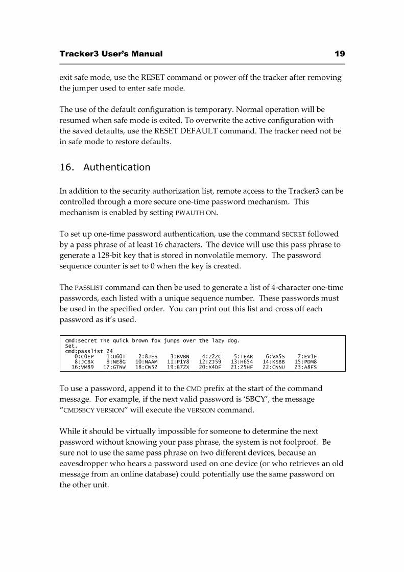
To set up one-time password authentication, use the command SECRET followed
by a pass phrase of at least 16 characters. The device will use this pass phrase to
generate a 128-bit key that is stored in nonvolatile memory. The password
sequence counter is set to 0 when the key is created.
The PASSLIST command can then be used to generate a list of 4-character one-time
passwords, each listed with a unique sequence number. These passwords must
be used in the specified order. You can print out this list and cross off each
password as it’s used.
To use a password, append it to the CMD prefix at the start of the command
message. For example, if the next valid password is ‘SBCY’, the message
“CMDSBCY VERSION” will execute the VERSION command.
While it should be virtually impossible for someone to determine the next
password without knowing your pass phrase, the system is not foolproof. Be
sure not to use the same pass phrase on two different devices, because an
eavesdropper who hears a password used on one device (or who retrieves an old
message from an online database) could potentially use the same password on
the other unit.
cmd:secret The quick brown fox jumps over the lazy dog. Set. cmd:passlist 24 0:C0EP 1:U60T 2:8JES 3:BVBN 4:Z2ZC 5:TEAR 6:VA5S 7:EV1F 8:JCBX 9:NE8G 10:NAAM 11:P1Y8 12:ZJ59 13:H654 14:KSBB 15:PDM8 16:VM89 17:GTNW 18:CW52 19:B7ZX 20:X4DF 21:Z5HF 22:CNNU 23:A8FS
Tracker3 User’s Manual 20
Also, should a valid password be sent without being received by the target
device, an eavesdropper would know the next valid password. If you are unsure
of being able to reach the target device, send an unauthenticated message or
query first and make sure you get a reply.
17. Garmin Fleet Management Interface
Some Garmin navigation systems provide a Fleet Management Interface (FMI)
that can be used with the Tracker3 with the proper cable. See
http://wiki.argentdata.com for current compatibility information and cable
requirements.
To use the FMI features, set one of the Tracker3’s serial ports to GARMIN mode
and connect the FMI cable. The Tracker3 will automatically place the navigation
system in fleet management mode, which adds a ‘Dispatch’ menu item and may
change the layout of other menus. This mode change can only be reversed by
erasing all user data on the navigation system
Incoming APRS messages will display a message icon on the navigation system’s
screen and will be stored in the inbox. Outgoing messages can be addressed to a
specific station by starting the message with a dash (‘-‘) and the destination
callsign, followed by a space and the message text. If no station is specified, the
message will be sent to the sender of the last message received. This allows
conversations to be carried on without having to constantly re-enter callsigns.
To send a configuration command to the Tracker3, start a message with ‘--’. For
example, ‘--VERSION’ will cause the Tracker3 to respond with a message stating
its firmware version.

Tracker3 User’s Manual 21
OTWINCFG Configuration Program
The Tracker3 can be configured using the otwincfg.exe program under
Windows. The program is available for download at
http://www.argentdata.com/support.
Connect the tracker and start the configuration program. The first window
displayed allows you to select the COM port that the tracker is connected to.
17.1. Overwriting an Invalid Configuration
The ‘Erase device and load new firmware’ option will load a new firmware
image, using the default configuration settings, without attempting to read the
existing configuration first. This is particularly useful if the tracker has an invalid
or missing configuration.
17.2. Turbo Mode
By default, the configuration program will attempt to connect at 115,200 baud. If
you have trouble connecting, use the ‘Disable Turbo’ option to force the program
to connect at 19,200 baud. This setting has no effect when connecting via USB.
17.3. Auto-detect ports
Selecting this option will cause the program to constantly scan all of the ports
and display which are available. Connecting the tracker via USB while this
option is checked will cause the program to automatically connect. On some
systems this option may cause trouble connecting; disable it if you experience
problems.
Tracker3 User’s Manual 22
17.4. Warm Boot vs. Cold Boot
If the unit is already powered on and operating when you click the ‘Connect’
button, the program attempts a ‘warm boot’ operation to put the device into
configuration mode. If the firmware has been corrupted, i.e. by a failed upgrade,
it may fail to enter configuration mode. You can correct this by performing a
‘cold boot’ - power the unit off and power it on again after clicking ‘Connect’.
The cold boot procedure cannot be used with a USB connection.
17.5. Working Offline
If you need to edit a configuration without connecting the tracker, click the
‘Offline’ button. You will need to have a saved configuration file to work from.
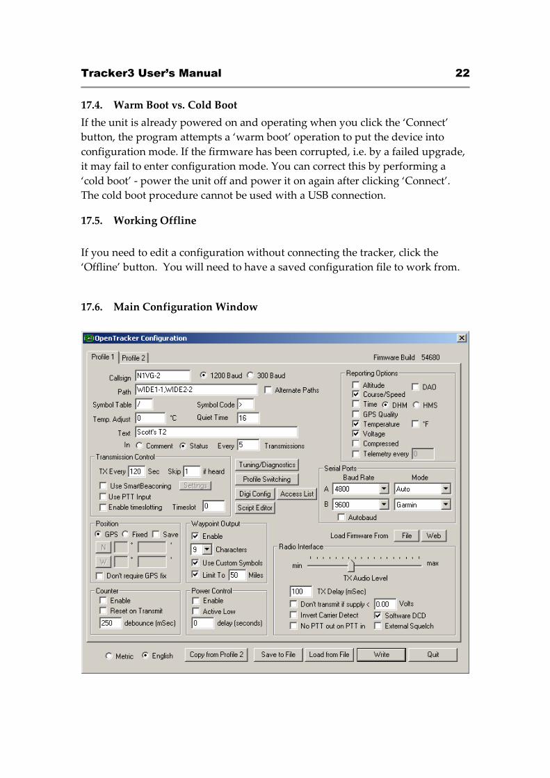
17.6. Main Configuration Window
Tracker3 User’s Manual 23
17.7. Configuration Profiles
The Tracker3 can store two separate configuration profiles. The profile currently
being shown is selected using the tabs at the top of the window labeled ‘Profile 1’
and ‘Profile 2’.
When it is first powered on, the Tracker3 will always start out using Profile 1.
After startup, profile selection depends on the settings in the profile switching
screen. To access these settings, click ‘Profile Switching’. See the section below
on profile switch for more information.
17.8. Loading and Saving Settings
After changing any configuration options, you must click the ‘Write’ button to
write the changes to the tracker’s firmware. You may also use the ‘Save to File’
button to save the configuration options to a file, which can be loaded later using
the ‘Load from File’ button.
17.9. Basic Configuration Options
Callsign – The radio callsign to use when transmitting. Tactical callsigns may be
used, but FCC and ITU rules require periodic identification. If the actual callsign
is not used here, be sure to include it in the comment field.
Baud Rate – For normal VHF operation this should be 1200. 300 baud is
commonly used for HF. The Tracker3 uses mark and space frequencies of 1600
and 1800 hz respectively in 300 baud mode.
Path – This specifies the digipeater path to use. Specific callsigns may be entered
(e.g., ‘K6SYV-10, K6TZ-10’) but for APRS operation a set of common aliases are
usually used. A suggested default path is ‘WIDE1-1, WIDE2-1’. It is rarely
necessary to use a path greater than WIDE3-3 (requesting three ‘wide’ digipeater
hops), and excessive paths generate large amounts of traffic that degrade the
performance of the network. If you’re not sure what path should be used for
your local area, check with a local digipeater operator. This field may be left
blank.
Tracker3 User’s Manual 24
Alternate Paths - When enabled, this option causes the tracker to alternate
between the paths specified in either profile with each transmission.
Symbol Table and Symbol Code – These settings control the symbol used to
indicate the station’s position when drawn on a map. See Appendix B for a
listing of available symbols. Common symbols can be selected using a drop-
down menu.
Temp. Adjust – Calibration offset for onboard temperature sensor. The sensor
used on the tracker is fairly linear across its operating range and requires a
single-point calibration. The easiest way to accomplish this is to set a
thermometer next to the tracker. Subtract the temperature reported by the tracker
from the temperature shown by the thermometer, and enter that value in this
field. For example, if the thermometer shows the temperature as 26°C and the
tracker reports 29°C, enter –3 for the adjustment value.
Quiet Time – This setting determines how long the channel must be clear before
the tracker will transmit. Each unit is approximately 1/56 second. Setting the
quiet time to zero causes the tracker to ignore detected traffic.
Text – This is a freeform text field. Anything entered here will be displayed in
the comment portion of the transmission or in a separate status packet, as
selected. Keep comments as brief as possible to avoid wasting channel capacity,
or use the ‘Every __ Transmissions’ option to reduce how often the text is sent.
Altitude, Course/Speed, Time – When checked, report these values as indicated
by the GPS receiver. The timestamp may be in Days/Hours/Minutes or
Hours/Minutes/Seconds.
DAO – Enables the proposed !DAO! APRS extension to provide the map datum
used and an extra digit of latitude and longitude resolution. May not be
supported by all APRS clients. The datum is always reported as WGS84, which
is the standard for normal APRS operation.
GPS Quality – Report number of satellites in use and horizontal dilution of
precision information as reported by the GPS receiver.
Temperature – Report temperature as indicated by the onboard temperature
sensor in the comment field. The temperature may be reported in Celsius (the
default option) or Fahrenheit degrees.
Tracker3 User’s Manual 25
Voltage – Report input voltage in the comment field. The maximum value is 18.5
volts, and the minimum is the dropout voltage of the regulator – typically 6.7
volts.
Compressed – Enables Base91 compressed position reporting. This mode is
widely, but not universally, supported. Packets in Base91 format are shorter
than their uncompressed equivalents and provide greater position resolution.
Telemetry every n – Sends a telemetry packet every n transmissions. See the
telemetry section for more details.
TX Interval – How often the tracker should transmit. Allowable values are 0 to
65,535 seconds. This setting will depend on your intended use. One transmission
every two minutes is acceptable for most mobile stations. A fixed station (e.g., a
solar powered site reporting battery voltage and temperature) might choose an
interval in the range of 5 to 30 minutes. If you require transmissions more often
than every two minutes or so, consider using the SmartBeaconing™ options
detailed below. Special events with many trackers and short transmission
intervals should be operated on a separate frequency, not on the shared APRS
channel. An interval of zero will disable timed transmissions.
SmartBeaconing – Originally developed for the HamHUD by Tony Arnerich,
KD7TA, and Steve Bragg, KA9MVA, the SmartBeaconing™ algorithm allows the
tracker to operate more efficiently by changing how often it transmits depending
on its speed and direction of travel.
When stopped or moving at a speed below the low speed setting, the tracker will
transmit at a fixed rate determined by the lower rate setting. Above the specified
high-speed threshold, the higher rate setting is used. Between these two
extremes, the interval varies between the low and high rates depending on the
speed. A turn angle can also be specified to cause the tracker to transmit when
turning. The final setting ensures that the tracker will never transmit more often
than the specified interval, regardless of speed and turn rate. This can be useful
to avoid transmitting more than once in a long, shallow turn.
Tracker3 User’s Manual 26
Use PTT Input – When this checkbox is enabled, the tracker can be connected
inline with a microphone to operate in burst-after-voice (mic encoder) mode. A
packet will be transmitted whenever the microphone PTT is released.
Timeslot – The timeslot option is typically used to coordinate multiple trackers,
especially for special events where many transmitters will be sharing the same
channel with a high beacon rate. The number entered selects the timeslot’s offset,
in seconds, from the start of the hour. The tracker will transmit at this time, and
every transmit interval after that. The timeslot value should be smaller than the
transmit interval.
As an example, two trackers could be configured with an interval of 10 seconds,
with one tracker set to slot 0 and the other to slot 5. The first tracker would
transmit at 12:00:00, 12:00:10, 12:00:20, and so on, while the second would
transmit at 12:00:05, 12:00:15, and 12:00:20.
The Tracker3 will accept timeslot settings in half-second increments.
Position – The tracker can operate in GPS or fixed position mode. When
entering a fixed position, enter degrees in the first box and decimal minutes in
the next box. Click on the buttons next to the coordinates to select North/South
and East/West.
Don’t require GPS fix – Normally, while in GPS mode, the tracker will not
transmit without a valid fix. When this option is selected, the tracker will
continue to transmit its last known position if GPS lock is lost for more than 30
seconds. This condition is indicated by the text ‘NOFIX’ in the status message. If
the tracker has received no valid fix since startup, no position will be reported.
Status text and telemetry packets will be unaffected. This option is particularly
Tracker3 User’s Manual 27
useful for applications like high altitude balloons that may lose GPS lock after
landing, but still need to transmit to be found.
Save – When enabled, the tracker will save its last-known GPS position as a
permanent fixed position if the GPS fix is lost. This may be used in the case of a
temporary digipeater or weather station where a GPS receiver is installed only
during setup and is removed to conserve power. The system must remain
powered on for 30 seconds after GPS fix loss before the position is saved.
Waypoint Output – Enabling the waypoint output option causes the tracker to
parse received APRS positions and output them over the serial port at 4800 baud.
Waypoints are provided in both NMEA 0183 format ($GPWPL sentence) and
Magellan format ($PMGNWPL sentence).
Length Limit – Some GPS receivers are not capable of display the full 9
characters required for APRS call signs and object names. Setting this option to a
smaller number causes the tracker to intelligently truncate the name of the
waypoint. Spaces and dashes are eliminated first, and if further truncation is
required, characters are dropped from the left first. This prevents stations with
different SSIDs from conflicting – for example, with a limit of 6 characters,
KB6YUO-12 and KB6YUO-6 would be truncated as 6YUO12 and B6YUO6
respectively.
Use Custom Symbols - Enables the use of custom symbols if they have been
uploaded to a compatible Garmin GPS receiver (using the Garmin xImage
utility).
Range Limit - When enabled, waypoints will only be created for stations and
objects within the specified range.
Enable Counter – This checkbox enables the digital counter function. When this
function is enabled, the tracker will no longer transmit immediately when the CT
pin on the terminal block (OT3m only) is shorted to ground. Instead, it will
increment a counter and include the current count in the status text, e.g.,
‘CNT00001’. The maximum count is 65535, after which the counter rolls over to
zero. This option can not be used concurrently with profile switching with the
‘jumper’ option.
Tracker3 User’s Manual 28
Reset on Transmit – Setting this checkbox causes the counter to reset with every
transmission. Hence, the count reported is the number of events since the last
transmission.
Debounce – This is a delay applied to the counter input. After a counter event is
registered, all subsequent events are ignored until the specified time has elapsed.
Without a suitable debounce setting, a typical pushbutton could register several
events for one press.
Power Control – When selected, the tracker will activate its internal solid state
relay before each transmission. The tracker will pause for the specified number of
seconds to give the transmitter time to power up. The power control feature is
especially useful for solar-powered weather or telemetry stations.
TX Audio Level – This slider sets the audio output level. This level can be set
interactively from the Tuning/Diagnostics screen. If you find that the required
level is less than one quarter of the full scale, make sure you have the ‘HI’ jumper
removed. Running with the audio level set in software to a very low level can
increase DAC quantization noise.
TX Delay – All radios require a certain amount of time to stabilize on their
transmitting frequency, and receivers also require time to lock on. This value
specifies the number of milliseconds the tracker should wait after the start of the
transmission before it begins sending data. Allowable values are 0 to 1023
milliseconds. Setting this value too high will keep the channel busy longer than
necessary. Setting it too low will prevent packets from being transmitted
properly. Finding the optimum value for your radio may require some
experimentation.
Don’t transmit if supply < n – To avoid over-discharging batteries, enable this
option and enter the minimum voltage at which the tracker should operate the
transmitter.
Invert Carrier Detect – Usually used with mobile radios, this checkbox indicates
that the channel is busy when the carrier detect input is low.
Software DCD – This option selects the data carrier detect (DCD) mode used.
When unchecked, the tracker considers the channel to be busy in the presence of
any noise, including voice or static. When checked, the channel is considered
busy only when a valid 1200 baud signal is present.
Tracker3 User’s Manual 29
No Suppress PTT Out on PTT In – This option allows the tracker to be used in
burst-after-voice mode without breaking any lines between the microphone and
radio. PTT is not asserted by the tracker until the microphone PTT is released.
External Squelch – Enables the use of an external squelch or COR input.
Copy from Profile n – This button copies the contents of one profile to the other.
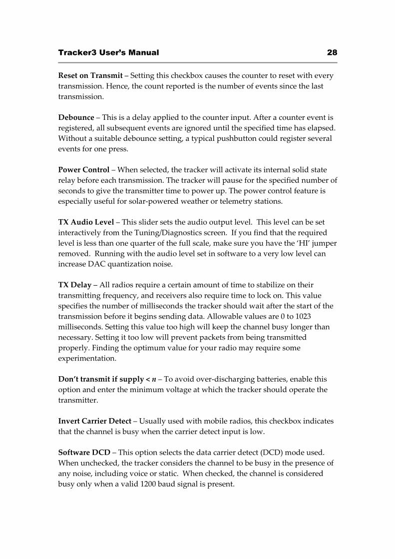
17.10. Tuning and Diagnostics
Access the tuning and diagnostics screen with the ‘Tuning/Diagnostics’ button.
From this screen, you can exercise the Tracker3 hardware and set the audio level.
The top row of buttons controls the red and green elements of the ACT LED, the
PTT output, and the power relay, and the second row allows AFSK tones to be
sent, either with or without PTT on. When both tone buttons are on, the tracker
sends alternating mark/space tones at the specified baud rate. The ‘Sensors’ pane
shows the raw readings from the on-board sensors. The temperature reading is
shown without the calibration constant applied.
Tracker3 User’s Manual 30
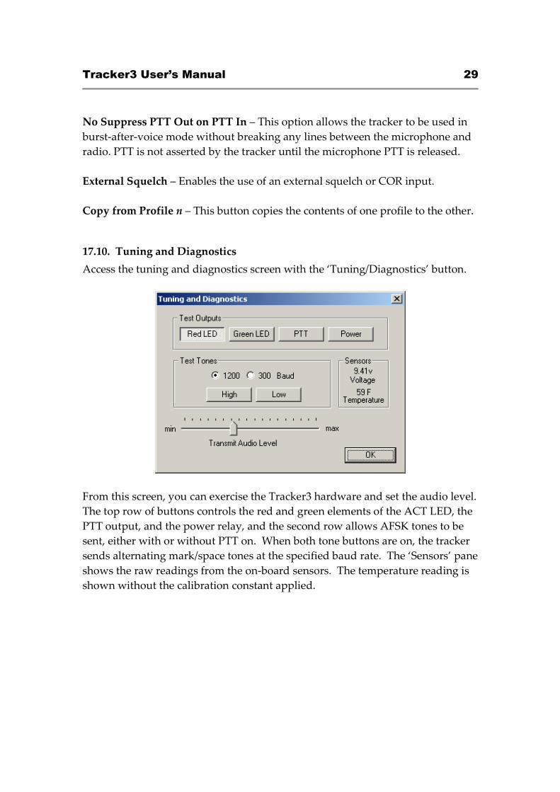
17.11. Access List
This screen allows editing of the tracker’s remote access control list.
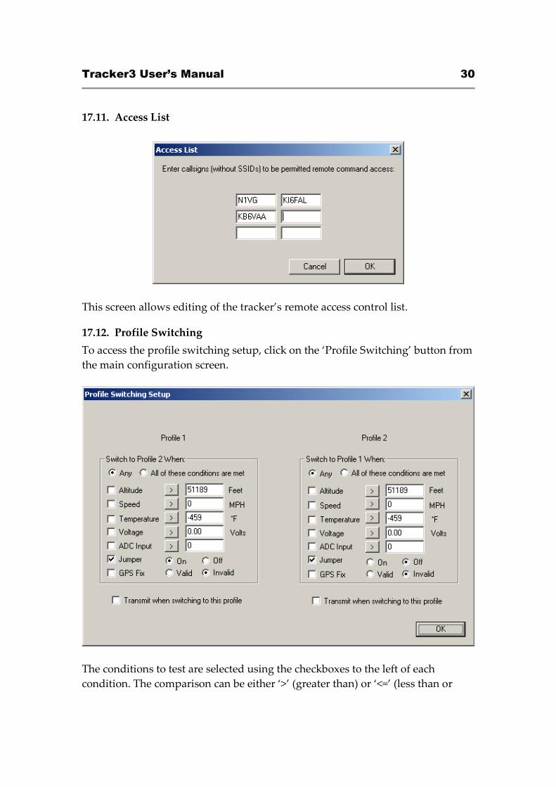
17.12. Profile Switching
To access the profile switching setup, click on the ‘Profile Switching’ button from
the main configuration screen.
The conditions to test are selected using the checkboxes to the left of each
condition. The comparison can be either ‘>’ (greater than) or ‘<=’ (less than or
Tracker3 User’s Manual 31
equal to). Clicking on the button showing the comparison operator toggles it
between these two settings.
The Altitude and Speed values are compared with those indicated by the GPS.
Onboard sensors provide readings for comparison with the Temperature and
Voltage fields. ADC Input refers to the extra unused analog-to-digital converter
input on X1 pin 9. The possible values are 0 to 255, corresponding to a range of 0
to 5 volts. The ‘jumper’ setting refers to the state of the IO input on the accessory
port. The input is ‘On’ when the IO pin is pulled to ground, as through a toggle
or pushbutton switch. An external pull-up resistor (typically 4.7k ohms) should
be used to pull the IO pin to 5v. The GPS Fix is considered invalid if it has been
more than 20 seconds since the last valid position was received from the GPS
unit.
The selected tests are run once every second. If the conditions are met, the new
profile is loaded. If Transmit when switching to this profile is checked in the new
profile, a packet is transmitted immediately.
If the conditions in both profile panes are met, the tracker will switch between
the two profiles each second and may cause undesired operation.
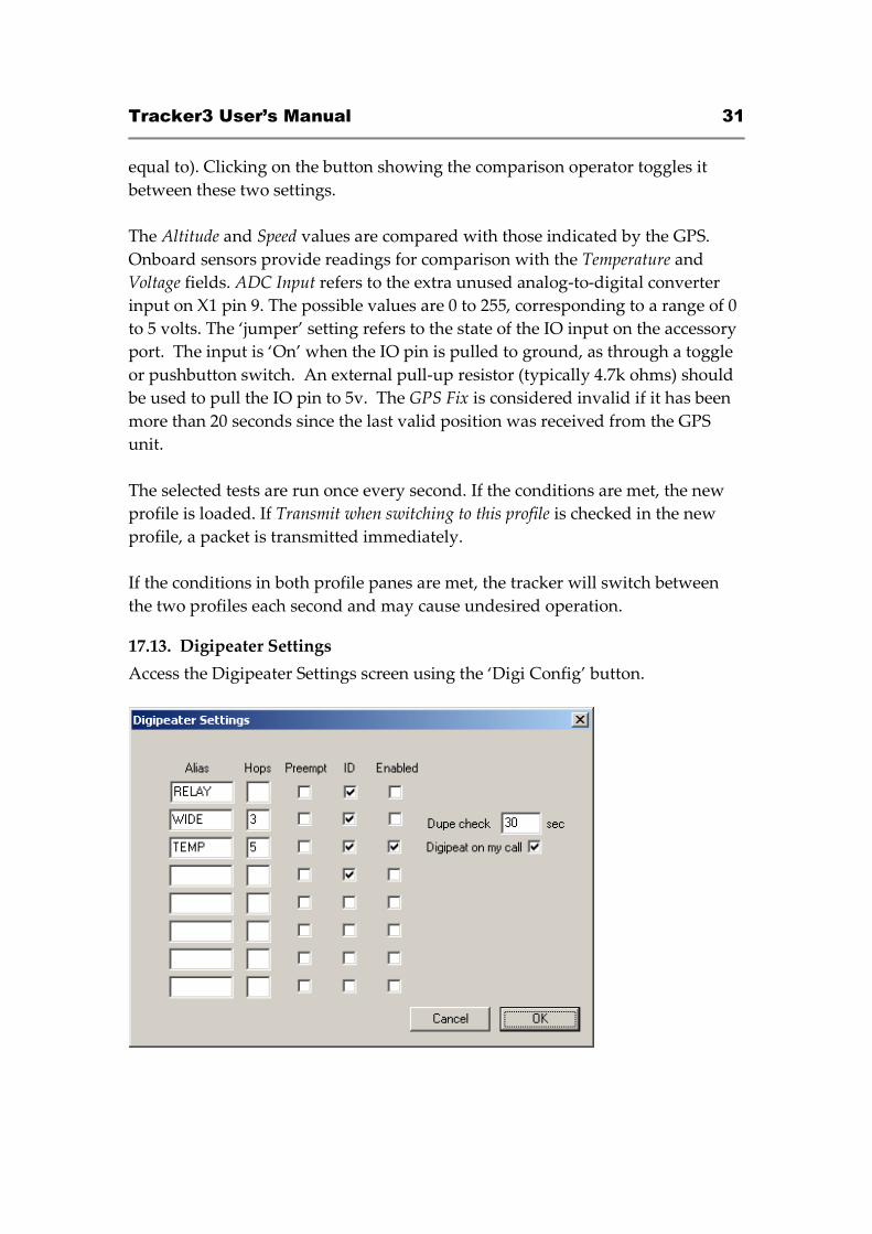
17.13. Digipeater Settings
Access the Digipeater Settings screen using the ‘Digi Config’ button.
Tracker3 User’s Manual 32
The ‘Digipeat on my call’ option causes the tracker to repeat packets with the
tracker’s own callsign in the packet’s digipeater list. This allows any Tracker3
with the default configuration to be used as a relay if explicitly selected by the
sending station.
The entries in the alias list specify other digipeater address that the unit should
respond to. Only those with the ‘Enabled’ checkbox checked will be used. The
‘Enabled’ option is set in each profile. All other alias settings are global and
affect both profiles.
‘Hops’ specifies the maximum number of hops to allow for this alias. This option
limits excessive paths.
Normally the unit will repeat a packet only if it finds a match in its alias list for
the next unused address entry in the packet’s digipeater list. The ‘Preempt’
option tells the tracker to honor the alias if it appears anywhere in the digipeater
list.
‘ID’ causes insertion of the tracker’s callsign in the packet’s digipeater list,
allowing the actual path of a packet to be traced.
Each packet is checked against a duplicate list to avoid multiple transmissions of
the same packet. The ‘Dupe check’ time setting determines how long entries are
kept in this list.
17.14. Script Editor
The ‘Script Editor’ button activates the script editor, documented in its own
chapter in this manual.
Tracker3 User’s Manual 33
18. Command Reference
Most commands can be issued through the serial console, APRS message, or fleet
management message. Some commands make sense only when used from the
local console and are not available for remote access.
The Tracker3 will accept command abbreviations. A minimum of three
characters must be entered. For example, CALIBRATE can be entered as CAL.
AUTOBAUD can be entered as AUTOB, the additional characters being required to
distinguish it from AUTOSAVE.
Many commands return values in the script engine’s ‘Result’ variable. On/Off
commands return 1 for ‘On’ and 0 for ‘Off’. Numeric settings return the value of
the setting. Other return values are documented below in italics.
1WIREWX
Enables 1-Wire Weather Station mode. The TAI8515 weather station (or a
DS18S20 temperature sensor alone) should be connected to the 1-wire bus.
ABAUD 1200 | 2400 | 4800 | 9600 | 19200 | 38400 | 57600 | 115200
Sets baud rate for the primary serial port. Default is 4800 baud.
Return value: 99 = invalid setting, 0-7 = 300 to 115200 baud
ALIAS <n> <callsign>
Sets digipeater alias for slot <n>, where n is between 1 and 8. This will
typically be a generic alias like 'WIDE'. No SSID is allowed in this field.
ALTITUDE on|off
Report altitude in position packet.
ALTPATH on|off
Causes the tracker to alternate between the digipeater path entries in
either profile with each transmission.
AMODE AUTO | GARMIN | KISS | DAVIS | WS2300
Sets mode for primary serial port. See ‘Port Modes’ above for more
information.
Tracker3 User’s Manual 34
ANALOG <n>
Returns the current reading for the specified analog input pin. See the
telemetry section of this manual for details on pin assignments. This
command is used primarily for scripting.
Return value: Current analog reading for specified pin
AUTHLIST +/-<callsign>
Displays or changes the list of callsigns authorized for remote access.
+callsign adds a callsign to the list, -callsign removes a callsign from the
list, and 'none' erases the entire list. Up to six callsigns can be stored.
AUTOBAUD on|off
Enables automatic baud rate detection. When a baud rate mismatch is
detected, the unit will attempt to automatically select the proper baud
rate.
AUTOSAVE on|off
When enabled, the tracker will save its last-known GPS position as a
permanent fixed position if the GPS fix is lost. This may be used in the
case of a temporary digipeater or weather station where a GPS receiver is
installed only during setup and is removed to conserve power. The
system must remain powered on for 30 seconds after GPS fix loss before
the position is saved.
BBAUD 1200 | 2400 | 4800 | 9600 | 19200 | 38400 | 57600 | 115200
Sets baud rate for the secondary serial port. Default is 4800 baud.
Return value: 99 = invalid setting, 0-7 = 300 to 115200 baud
BEACON [text] (local only)
If no beacon text is specified, a position beacon (and weather beacon, if
applicable) will be queued for immediate transmission. If a text string is
entered, that text will be transmitted as an AX.25 text packet.
The command ‘BEACON W’ will transmit only a weather packet, and
‘BEACON P’ will transmit a position packet.
BMODE AUTO | GARMIN | KISS | WS2300 | DAVIS | FLOW
Sets mode for secondary serial port. See ‘Port Modes’ above.
Tracker3 User’s Manual 35
CALIBRATE LOW | HIGH | ALT | PACKET (local only)
Calibration functions to set demodulator tuning and transmitter
deviation. 'Low' transmits a 1200 hz tone, 'high' transmits a 2200 hz tone,
'alt' transmits alternating 1200 and 2200 hz tones, 'packet' sends a test
packet repeatedly, and 'tune' displays a tuning indicator for adjustment of
the demodulator. Use the '[' and ']' keys for coarse adjustment of the
transmit audio level, and '-' and '+' for fine adjustment. Press any other
key to exit calibration mode.
CDINVERT on|off
Inverts carrier detect input polarity.
CLIMB on|off
Enables rate-of-climb indication. Climb rate is reported in feet per minute,
positive or negative, immediately following the altitude. Available only
in Garmin binary mode.
CNTRESET on|off
Causes counter to reset with each transmission. See accessory port
information.
COMMENT <string>
Sets beacon text / comment string, up to 64 characters.
COMPRESS on|off
Enables Base91 compressed format for position transmissions.
CONFIG 1|2 (local only)
Selects configuration profile to modify.
CONVERSE (local only)
In converse mode, text entered at the console is transmitted when the
ENTER key is pressed. Hit CTRL-C to exit. The command ‘K’ may also
be used to enter CONVERSE mode.
COUNTER on|off
Transmits counter value in status text.
Tracker3 User’s Manual 36
CUSTSYM on|off
Enables the use of custom symbols if they have been uploaded to a
compatible Garmin GPS receiver (using the Garmin xImage utility).
CWBEACON <text> (local only)
Sends <text> as a Morse code beacon.
DAO on|off
Enables transmission of the !DAO! extended-precision construct. This
provides an extra digit of precision over the standard APRS position
format, but results in a longer packet and may not be supported by all
APRS clients.
DEVLIST (local only)
Lists addresses of all connected 1-wire devices.
Return value: Number of devices detected
DIGI on|off
When enabled, the tracker will digipeat packets having its own callsign
(MYCALL) in the next digipeater address field.
DIGIID <n> on|off
Enables callsign substitution for digipeater alias <n> (1 to 8). This should
normally be enabled.
DISPLAY (local only)
Lists all configuration parameters.
DOUBLE <n> on|off
When enabled, two identical copies of the position packet are sent with
each transmission. This should only be used with short packets when
extra redundancy is required.
DUMP (local only)
Displays the tracker’s memory contents for troubleshooting purposes. By
default only RAM contents are displayed. DUMP CONFIG displays
configuration memory contents, and DUMP ALL displays everything.
DUPETIME <0-255> (seconds)
Sets digipeating duplicate suppression period.
Tracker3 User’s Manual 37
ECHO [text]
Prints text to the console. Allows output from scripts when using the USB
console.
EXTSQL on | off
Enables external squelch input.
EXTTEMP on | off
Enables temperature reporting from an external DS18S20 temperature
sensor connected to the 1-wire data bus.
FAHRENHT on|off
Reports temperatures in Fahrenheit when temperature output in the
status text is enabled.
FILTER on | off
When FILTER is ON, the MONITOR command will only output printable
characters.
GPIO <n> on | off | toggle | in
Reads or sets state of a general-purpose digital I/O pin. ‘On’ sets the pin
to the high state, ‘Off’ sets it to low state, ‘Toggle’ reverses the state of the
pin, and ‘In’ switches the pin to input mode and returns 1 or 0 depending
on the input signal. This command is used primarily for scripting. Pin
output state settings are not retained when power is lost. See the
telemetry section of this manual for details on pin assignments.
Example: GPIO 1 ON
Return value: 0 or 1 depending on input signal
GPSDATA on|off
Reports GPS quality data in status text: Horizontal dilution of precision
and number of satellites for NMEA mode, or estimated position error for
Garmin mode.
HALFSLOT on|off
When timeslotting is enabled, HALFSLOT adds ½ second to the slot time.
HBAUD 1200|300
Tracker3 User’s Manual 38
Selects transmission baud rate. Note that the reception baud rate is fixed
at 1200 baud.
Return value: 99 = invalid setting, 0 = 1200, 1 = 300, 2 = PSK31
HEADERLN on|off
Breaks MONITOR packets into two lines, with header and payload
separated.
HOPLIMIT <n> <hops>
For digipeater alias <n> (1-8), sets the maximum number of digipeater
hops allowed. This can be used to limit excessively long paths that may
cause network degradation.
INFO
Displays general system and diagnostic data, including number of packets
heard, packets digipeated, and frame check sequence errors detected.
INTERVAL <0-65535> (seconds)
Sets the interval between automatic transmissions.
LVINHIBIT <0-255> (* 0.0784 volts)
Sets the low-voltage inhibit threshold. When the supply voltage drops
below this level, the unit will cease transmitting. Each unit is 0.0784 volts,
so a setting of 100 equals 7.84 volts.
MAXRANGE <0-255> (miles)
When set to a non-zero value, waypoints will only be created for stations
and objects within the specified range.
MONITOR on|off
Displays incoming packets on the console as they are received.
MYCALL <xxxxxx-nn>
Sets the unit's callsign and optional SSID.
NICE <n>
When the tracker hears one of its own packets digipeated, it will skip the
following <n> transmissions. This allows a faster beacon rate to be used in
areas with poor coverage, without increasing the load on the network in
areas with better coverage.

Tracker3 User’s Manual 39
PASSALL on|off
Normally the Tracker3 ignores all received packets that fail a frame check
sequence test. PASSALL disables the FCS test. This option should only be
used for troubleshooting as it will result in output of corrupted packets.
PASSLIST [n] (local only)
Generates a list of the next n one-time passwords to be used, based on the
pass phrase entered with the SECRET command. Default is 144.
PATCH <hex string>
The patch command allows direct modification of the contents of the
Tracker3’s flash memory. This command should only be used as directed
by the manufacturer. Improper use of this command may render the
Tracker3 inoperable.
PATH <call1,call2,…>
Comma-separated digipeater path list, containing up to three digipeater
addresses.
POSITION <hhmm.mmx hhhmm.mmx> | GPS
Sets fixed position or enable GPS. Position must be entered in degrees
and decimal minutes, including leading zeros. Setting position to 'GPS'
reverts to GPS tracking mode.
Example: POSITION 4851.49N 00217.66E
Return value: 0 = Using GPS, 1 = Fixed Position, 2 = Position Unknown
POWER on|off|<0-255> (seconds)
ON or OFF will manually set the state of the power output. Specifying a
value in seconds will enable automatic power control mode, where the
power output is turned on for the specified number of seconds prior to
transmission, and turned off immediately after transmission.
Return value: 0 = Off, 1 = On, 2 = Timed
PREEMPT <n> on|off
Enables digipeater preemption for alias <n> (1-8). If preemption is
enabled, packets will be digipeated on this alias even if it isn't the next
address in the packet’s digipeater list.
Tracker3 User’s Manual 40
PROFILE 1 | 2
Selects the configuration profile to use. If profile switching is enabled, the
profile switching parameters will still be in effect.
PROPWPT on|off
Enables proprietary waypoint strings. With PROPWPT OFF, output formats
are $GPWPL and $PGRMW. With PROPWPT ON, $PKWDWPL, $GPWPT,
and $PMGNWPL are output.
PTTINPUT on|off
Enables PTT input for mic encoder opration. A position packet will be
transmitted when the mic PTT is released. OT3m model only.
PULSE <0-255> (seconds)
Activates power output for specified duration.
PWAUTH on|off
Enables one-time password authentication.
QUIET <0-255>
Time channel must be free before transmission can occur, in 1/64 second
units.
REARM <0-255> (milliseconds)
Specifies minimum time between counter inputs. May be used for switch
de-bouncing.
REPLY <message> (local only)
Sends a text message to the last person who sent a message addressed to
this unit's callsign
Return value: 0 = No message received to reply to, 1 = Message received
RETRIES <0-255>
Number of times to retransmit an outgoing message.
RETRYTIME <0-255> (seconds)
Time between message retry attempts - interval increases by this value
with each transmission.
Tracker3 User’s Manual 41
REQALL on|off
Require all configuration switch parameters to be met before switching
profiles.
RESET
Perform software reset. Saved settings are unaffected.
RING on|off
Sends a bell character whenever an incoming message arrives.
SCRIPT on|off
Enables the script engine.
SECRET <pass phrase>
Sets the pass phrase for the one-time password authentication system.
SEND <callsign> <message> (local only)
Sends a text message to the designated recipient.
Return value: Number of retries remaining
SHAREDPTT on|off
Controls PTT line behavior for mic encoder mode. If enabled, PTT output
is not asserted until the PTT input is released.
SLOT <0-65535>
Time slot for transmission (if TIMESLOT is on). Slot position is counted in
seconds from the start of the hour.
SMARTBCON <low speed> <high speed> <low rate> <angle> <time>
Configures SmartBeaconing. The SmartBeaconing algorithm allows the
tracker to operate more efficiently by changing how often it transmits
depending on its speed and turn rate.
When stopped or moving at a speed below the low speed setting, the
tracker will transmit at a fixed rate determined by the lower rate setting.
Above the specified high-speed threshold, the higher rate setting is used.
Between these two extremes, the interval varies between the low rate and
high rate (specified separately with the INTERVAL command) depending
on the speed.
Tracker3 User’s Manual 42
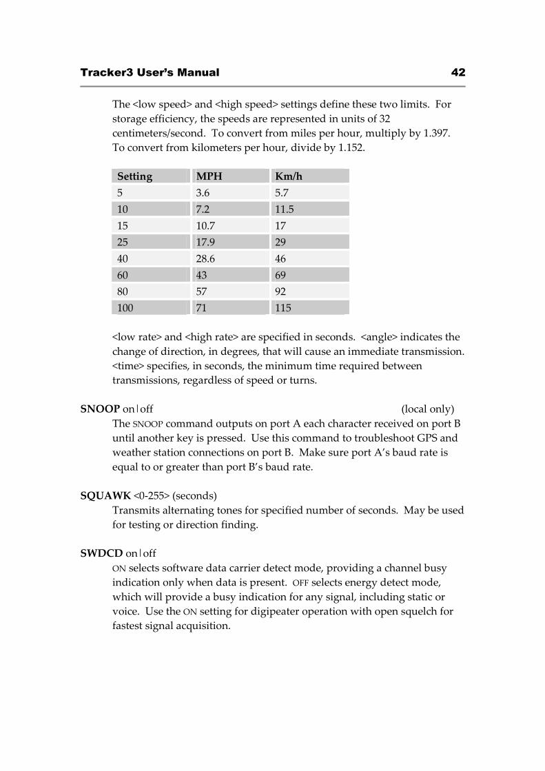
The <low speed> and <high speed> settings define these two limits. For
storage efficiency, the speeds are represented in units of 32
centimeters/second. To convert from miles per hour, multiply by 1.397.
To convert from kilometers per hour, divide by 1.152.
Setting MPH Km/h
5 3.6 5.7
10 7.2 11.5
15 10.7 17
25 17.9 29
40 28.6 46
60 43 69
80 57 92
100 71 115
<low rate> and <high rate> are specified in seconds. <angle> indicates the
change of direction, in degrees, that will cause an immediate transmission.
<time> specifies, in seconds, the minimum time required between
transmissions, regardless of speed or turns.
SNOOP on|off (local only)
The SNOOP command outputs on port A each character received on port B
until another key is pressed. Use this command to troubleshoot GPS and
weather station connections on port B. Make sure port A’s baud rate is
equal to or greater than port B’s baud rate.
SQUAWK <0-255> (seconds)
Transmits alternating tones for specified number of seconds. May be used
for testing or direction finding.
SWDCD on|off
ON selects software data carrier detect mode, providing a channel busy
indication only when data is present. OFF selects energy detect mode,
which will provide a busy indication for any signal, including static or
voice. Use the ON setting for digipeater operation with open squelch for
fastest signal acquisition.
Tracker3 User’s Manual 43
STATUS <0-255>
Status packets are sent every n transmissions, or if set to 0, status text is
sent as part of the position packet.
SYMBOL <1-2 characters>
APRS symbol character, optionally preceded by symbol table or overlay
identifier.
TELEMETRY on|off
Enables transmission of telemetry packets.
TEMP on|off
Enables transmission of temperature readings from the on-board
temperature sensor.
TEMPADJ <-128 to 127> (degrees C)
Offset for temperature sensor in degrees C.
TIMEHMS on|off
Sets timestamp mode to hour/minute/second when enabled. Default is
day/hour/minute. Applies only to NMEA mode – hour/minute/second
format is always used in Garmin binary mode.
TIMESLOT on|off
Force position packets to be transmitted only in designated time slots,
expressed as the number of seconds from the start of the hour to the first
transmission.
TIMESTAMP on|off
Report time information in the position packet.
TRACE on|off (local only)
When trace is on, each received raw packet is output in hexadecimal on
the active console port.
TXDELAY <0-255>
Delay between start of transmission and start of data. This setting should
be set to the minimum value that allows reliable reception of transmitted
packets. An excessively high TXDELAY setting wastes channel capacity.
Each unit is one character time – 1/150 second at 1200 baud.
Tracker3 User’s Manual 44
TXLEVEL <1-255>
Sets transmission audio level. This value should be selected to provide an
appropriate FM deviation level, typically about 3.5 kHz.
TXNOFIX on|off
Allows transmission of last position if GPS fix is lost for more than 30
seconds. Default behavior is to cease transmitting the position in the
absence of a valid GPS signal.
TXONCHG on|off
Causes an immediate transmission when switching configuration profiles.
USEALIAS <n> on|off
Enables digipeating for alias n.
VELOCITY on|off
Enables transmission of velocity (course and speed) information in the
position packet.
VERSION
Displays firmware version number. For normal firmware releases,
indicates date of release in Modified Julian Day format.
Return value: Version number
VOLTAGE on|off
Enables reporting of supply voltage in status text.
WAYPOINTS on|off
Enables output of waypoints from received positions.
WPTLEN <6-9>
Sets maximum waypoint name length.
WXINFO
Displays weather information from attached station.
Tracker3 User’s Manual 45
19. Telemetry
All Tracker3 models have the ability to send telemetry information from their on-
board sensors, and some models include external analog and digital telemetry
inputs.
The OT3m and T3-301 can measure and report their supply voltage, and all
models include a temperature sensor – though the on-board sensors on the T3-
135 and T3-301 reflect the temperature inside the radio enclosure, and are
generally more useful for monitoring the condition of the equipment than the
ambient temperature.
When telemetry reporting is enabled, the tracker transmits standard APRS
telemetry reports in the following format:
T#sss,aaa,bbb,ccc,ddd,eee,76543210
The ‘sss’ field is a sequence number that increments with each report. Fields
‘aaa’ through ‘eee’ encode five channels of analog readings from 0 to 255, and
fields 7 through 0 are binary bits, either 0 or 1, representing digital inputs.
The ‘aaa’ field represents the tracker’s supply voltage, and fields ‘bbb’ through
‘eee’ correspond to inputs A1 through A4 respectively. For the OT3m, all
voltages are reported in 1/10 volt units.
While the T3-135 board has no externally accessible analog inputs, four pads
marked A1 through A4 are present on the board and may be used for analog
telemetry, with readings of 0 to 255 representing 0 to 5 volts.
Digital bit 1 reflects the state of the OT3m’s terminal block ‘IO’ pin, and bit 0
indicates the configuration profile currently in use.
Tracker3 User’s Manual 46
20. Script System
The Tracker3’s script engine allows simple programs to be run on the tracker to
customize the tracker’s operation and automate tasks. Use the ‘script’ button in
the otwincfg utility to access the script editors.
Common script tasks include handling multiple beacon texts, responding to
events such as door alarms or high temperatures, transmitting APRS objects or
telemetry parameters, and changing regional settings automatically. Detailed
information on all script commands and additional example scripts can be found
at wiki.argentdata.com.
20.1. Script Editor
Scripts are created in otwincfg and uploaded to flash memory in the tracker.
When the SCRIPT option is enabled, the script is executed 8 times per second. If
the 'Quick' command is used in the script, the script will execute again in one
timer tick – 1/1200 second on the Tracker3.
Scripts cannot be remotely edited directly, but the script editor can generate a list
of PATCH commands that will allow a prepared script to be uploaded to a
remote tracker. Make sure the SCRIPT option is turned off while the script is
being uploaded. Turn the script option on, when you are ready to run scripts.
The editor screen is divided into three main parts. The top left portion is the
script listing, the bottom left portion allows data entry, and the right side
provides buttons for all script commands.
Tracker3 User’s Manual 47
The highlighted line in the script listing shows where the next command will be
inserted. The 'Delete Line' button deletes the currently selected line, and the 'Up'
and 'Down' buttons move the line in the listing. Conditional commands cause
automatic indentation in the listing. The numbers directly under the listing show
the amount of script memory used.
Commands that accept one or more parameters use the values in the A, B, C, T,
X, Y, area corners, and flags fields. A and B allow selection of three general-
purpose 16-bit counters that are used only within the scripting engine, as well as
a number of other system variables. C allows entry of numeric constants, T is for
text entry, the area corners allow a geographic area to be defined in terms of
northwest and southeast corner coordinates, and the flag checkboxes represent
"set", "clear", and "don't care" states.

Tracker3 User’s Manual 48
To compare the current altitude to a fixed value, for example, you can select
"Altitude" in box A and enter "10000" in box C, and click the "If A > C" button to
create the line "If Altitude > 10000". The next command entered will be indented,
indicating that it will only be executed if that condition is true. The "End Block"
command ends the conditional statement. "Else" reverses the sense of the last
conditional statement and should be used before the closing "End Block".
20.2. Script Commands
Do Once
This command is used in conjunction with a conditional statement to execute a
block of code once once for each time that the condition becomes true. This
makes it very useful for ensuring that a command is not executed repeatedly.
The "Do Once" command can be used at most 16 times in one script.
Macro T / Macro Out
The following block is executed when the command named in T is entered at the
command line, through the FMI interface, or by APRS message. The Macro Out
command responds to the macro through the same channel
If In Area
Executes the following block if the tracker's current location is within the defined
geographic area. Coordinates are entered in degrees and decimal minutes, but
are displayed in decimal degrees.
If Profile 1 / If Profile 2
Executes code based on the currently active profile.
If A = B / If A < B / If A > B
Compares two 16-bit counters.
If A = C / If A < C / If A > C
Compares a counter to a constant value.
Tracker3 User’s Manual 49
On Startup
Executes a block of code only once, immediately after the tracker is powered on.
On Second
Executes a block of code once per second.
On Interrupt
Executes a block of code whenever a low-going edge is detected on the CT
(counter/trigger) pin.
On GPS Fix
Executes the following block whenever a valid GPS position fix is obtained.
Set A = B
Sets a counter to the value in another counter.
Set A = C
Sets a counter to the value specified in box C.
Increment A / Decrement A
Increments or decrements the specified counter by one.
Port A Print / Port B Print
Sends a string to the specified serial port.
Execute T
Executes the text in T as if it was entered at the command line. The command’s
return value will be stored in the ‘Result’ variable.
Tracker3 User’s Manual 50
Use this command carefully - the tracker's flash memory has a write endurance
of about 100,000 cycles, and any command that changes a value in the tracker's
configuration will require a flash write. At 8 script executions per second, an
errant script could wear out the flash memory in a few hours. Flash writes also
cause the received packet buffer to be discarded. Use flags or ‘Do Once’ to avoid
executing the same command repeatedly.
Quick
Causes the script engine to start again in 1/1200 second instead of 1/8 second.
This can be useful when higher timing resolution is required.
Peek C&X=Y?
Reads the contents of memory location C, performs a logical AND with X, and
compares the result to Y. Use of this command requires knowledge of the
tracker's memory map.
Poke C,X&Y
Sets the contents of memory location C with the value in X, using Y as a bit mask.
Set Flags / Toggle Flags / Clear Flags
Sets, toggles, or clears the selected flags.
If Flags
Executes the following code block if the flags match the specified pattern. A
grayed-out checkbox indicates a "don't care" condition. This is shown in the code
listing with an 'x'.
20.3. Counters
Three general-purpose counter variables are reserved for scripting use, and other
system values are also accessible. All counters are unsigned 16-bit integers, and
will wrap from 65535 back to 0.
Counter 1 - Counter 3

Tracker3 User’s Manual 51
These general-purpose counters have no predefined meaning, and they have no
effect on the rest of the system.
Ticks
This counter increments every 1/1200 second, and counts from 0 to 1199.
TX Counter
Seconds elapsed since the last automatic transmission.
Second
This counter indicates the second of the current hour (synchronized to GPS time)
from 0 to 3599.
Pulse Count
This counter is used by the event counter function described elsewhere in this
manual.
Last Digi
Seconds elapsed since the tracker last heard one of its own packets repeated by a
digipeater.
Last Fix
Seconds elapsed since the last valid GPS position fix was received.
Altitude
Current altitude reported by the GPS receiver. Units are 2.56 meters, and 0
indicates an altitude of -10,000 meters. Thus, a value of 5097 is approximately
10,000 feet or 3,048 meters ((3,048 meters + 10,000) / 2.56 = 5096.875).
Result
Return value of the last command line command executed.
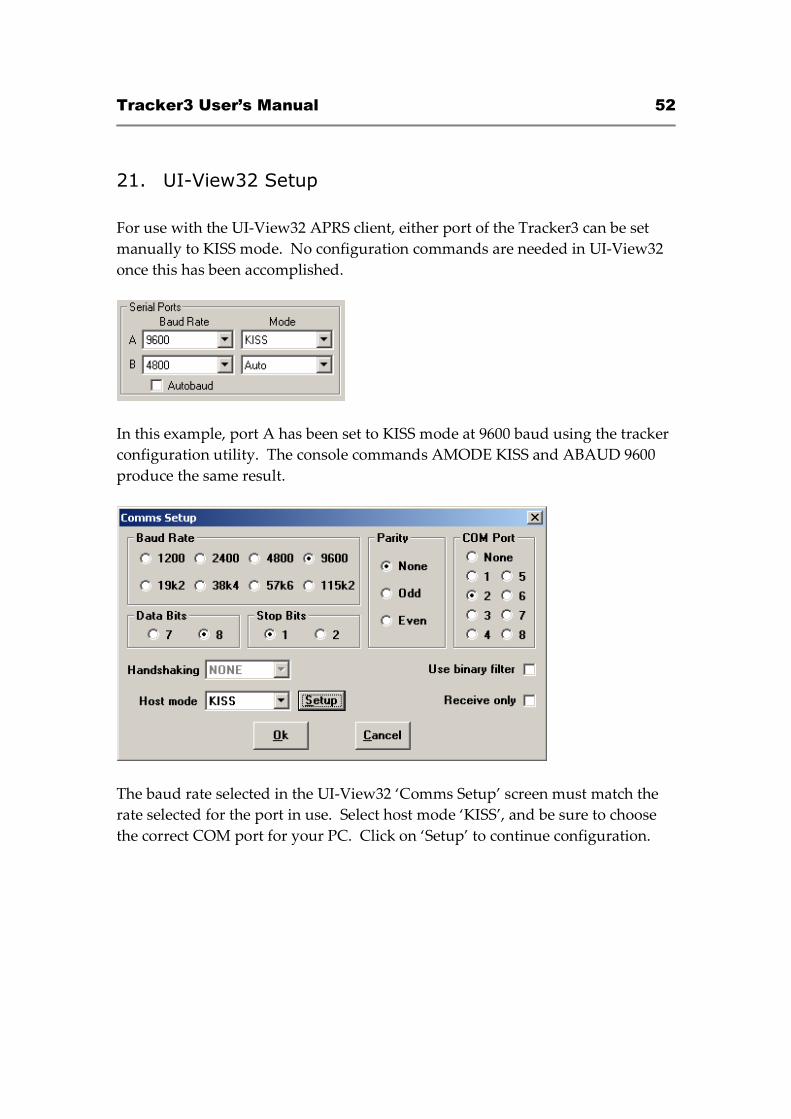
Tracker3 User’s Manual 52
21. UI-View32 Setup
For use with the UI-View32 APRS client, either port of the Tracker3 can be set
manually to KISS mode. No configuration commands are needed in UI-View32
once this has been accomplished.
In this example, port A has been set to KISS mode at 9600 baud using the tracker
configuration utility. The console commands AMODE KISS and ABAUD 9600
produce the same result.
The baud rate selected in the UI-View32 ‘Comms Setup’ screen must match the
rate selected for the port in use. Select host mode ‘KISS’, and be sure to choose
the correct COM port for your PC. Click on ‘Setup’ to continue configuration.
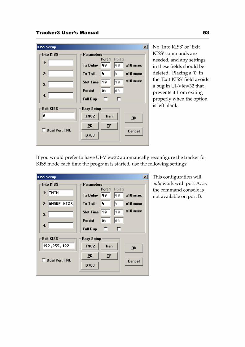
Tracker3 User’s Manual 53
No ‘Into KISS’ or ‘Exit
KISS’ commands are
needed, and any settings
in these fields should be
deleted. Placing a ‘0’ in
the ‘Exit KISS’ field avoids
a bug in UI-View32 that
prevents it from exiting
properly when the option
is left blank.
If you would prefer to have UI-View32 automatically reconfigure the tracker for
KISS mode each time the program is started, use the following settings:
This configuration will
only work with port A, as
the command console is
not available on port B.