Embed Size (px)
Citation preview
A review on polymer nanofibers by electrospinning andtheir applications in nanocomposites
Zheng-Ming Huanga,*, Y.-Z. Zhangb, M. Kotakic, S. Ramakrishnab,c,d
aDepartment of Engineering Mechanics, Tongji University, 1239 Siping Road, Shanghai, PR ChinabDivision of Bioengineering, National University of Singapore, 10 Kent Ridge Crescent 119260, Singapore
cNanoscience and Nanotechnology Initiative, National University of Singapore, 10 Kent Ridge Crescent 119260, SingaporedDepartment of Mechanical Engineering, National University of Singapore, 10 Kent Ridge Crescent 119260, Singapore
Received 21 January 2003; received in revised form 7 April 2003; accepted 8 April 2003
Abstract
Electrospinning has been recognized as an efficient technique for the fabrication of polymer nanofibers. Various polymers have
been successfully electrospun into ultrafine fibers in recent years mostly in solvent solution and some in melt form. Potentialapplications based on such fibers specifically their use as reinforcement in nanocomposite development have been realized. In thispaper, a comprehensive review is presented on the researches and developments related to electrospun polymer nanofibers including
processing, structure and property characterization, applications, and modeling and simulations. Information of those polymerstogether with their processing conditions for electrospinning of ultrafine fibers has been summarized in the paper. Other issuesregarding the technology limitations, research challenges, and future trends are also discussed.
# 2003 Elsevier Ltd. All rights reserved.
Keywords: Electrospinning
1. Introduction
When the diameters of polymer fiber materials areshrunk from micrometers (e.g. 10–100 mm) to sub-microns or nanometers (e.g. 10�10�3–100�10�3 mm),there appear several amazing characteristics such asvery large surface area to volume ratio (this ratio for ananofiber can be as large as 103 times of that of amicrofiber), flexibility in surface functionalities, andsuperior mechanical performance (e.g. stiffness and ten-sile strength) compared with any other known form ofthe material. These outstanding properties make thepolymer nanofibers to be optimal candidates for manyimportant applications. A number of processing techni-ques such as drawing [118], template synthesis [45,108],phase separation [106], self-assembly [104,161], electro-spinning [29,49], etc. have been used to prepare polymernanofibers in recent years. The drawing is a processsimilar to dry spinning in fiber industry, which can
make one-by-one very long single nanofibers. However,only a viscoelastic material that can undergo strongdeformations while being cohesive enough to supportthe stresses developed during pulling can be made intonanofibers through drawing. The template synthesis, asthe name suggests, uses a nanoporous membrane as atemplate to make nanofibers of solid (a fibril) or hollow(a tubule) shape. The most important feature of thismethod may lie in that nanometer tubules and fibrils ofvarious raw materials such as electronically conductingpolymers, metals, semiconductors, and carbons can befabricated. On the other hand, the method cannot makeone-by-one continuous nanofibers. The phase separa-tion consists of dissolution, gelation, extraction using adifferent solvent, freezing, and drying resulting in ananoscale porous foam. The process takes relativelylong period of time to transfer the solid polymer intothe nano-porous foam. The self-assembly is a process inwhich individual, pre-existing components organizethemselves into desired patterns and functions. How-ever, similarly to the phase separation the self-assemblyis time-consuming in processing continuous polymernanofibers. Thus, the electrospinning process seems to
0266-3538/03/$ - see front matter # 2003 Elsevier Ltd. All rights reserved.
doi:10.1016/S0266-3538(03)00178-7
Composites Science and Technology 63 (2003) 2223–2253
www.elsevier.com/locate/compscitech
* Corresponding author. Tel.: +86-21-65985373; fax: +86-21-
65982914.
E-mail address: [email protected] (Z.-M. Huang).
be the only method which can be further developed formass production of one-by-one continuous nanofibersfrom various polymers.Although the term ‘‘electrospinning’’, derived from
‘‘electrostatic spinning’’, was used relatively recently (inaround 1994), its fundamental idea dates back morethan 60 years earlier. From 1934 to 1944, Formalaspublished a series of patents [51–55], describing anexperimental setup for the production of polymer fila-ments using an electrostatic force. A polymer solution,such as cellulose acetate, was introduced into the electricfield. The polymer filaments were formed, from thesolution, between two electrodes bearing electricalcharges of opposite polarity. One of the electrodes wasplaced into the solution and the other onto a collector.Once ejected out of a metal spinnerette with a smallhole, the charged solution jets evaporated to becomefibers which were collected on the collector. The poten-tial difference depended on the properties of the spin-ning solution, such as polymer molecular weight andviscosity. When the distance between the spinneretteand the collecting device was short, spun fibers tendedto stick to the collecting device as well as to each other,due to incomplete solvent evaporation.In 1952, Vonnegut and Neubauer were able to pro-
duce streams of highly electrified uniform droplets ofabout 0.1 mm in diameter [153]. They invented a simpleapparatus for the electrical atomization. A glass tubewas drawn down to a capillary having a diameter in theorder of a few tenths of millimeter. The tube was filledwith water or some other liquid and an electric wireconnected with a source of variable high voltage (5–10kV) was introduced into the liquid. In 1955, Drozininvestigated the dispersion of a series of liquids intoaerosols under high electric potentials [37]. He used aglass tube ending in a fine capillary similar to the oneemployed by Vonnegut and Neubauer. He found thatfor certain liquids and under proper conditions, theliquid was issued from the capillary as a highly dis-persed aerosol consisting of droplets with a relativelyuniform size. He also captured different stages of thedispersion. In 1966, Simons patented an apparatus forthe production of non-woven fabrics of ultra thin andvery light in weight with different patterns using elec-trical spinning [136]. The positive electrode wasimmersed into the polymer solution and the negativeone was connected to a belt where the non-woven fabricwas collected. He found that the fibers from low visc-osity solutions tended to be shorter and finer whereasthose from more viscous solutions were relatively con-tinuous. In 1971, Baumgarten made an apparatus toelectrospin acrylic fibers with diameters in the range of0.05–1.1 microns [6]. The spinning drop was suspendedfrom a stainless steel capillary tube and maintainedconstant in size by adjusting the feed rate of an infusionpump. A high-voltage dc current was connected to the
capillary tube whereas the fibers were collected on agrounded metal screen.Since 1980s and especially in recent years, the elec-
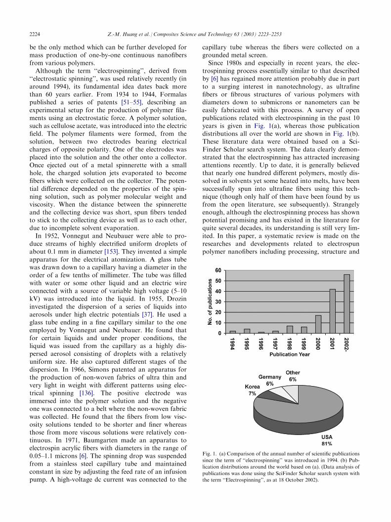
trospinning process essentially similar to that describedby [6] has regained more attention probably due in partto a surging interest in nanotechnology, as ultrafinefibers or fibrous structures of various polymers withdiameters down to submicrons or nanometers can beeasily fabricated with this process. A survey of openpublications related with electrospinning in the past 10years is given in Fig. 1(a), whereas those publicationdistributions all over the world are shown in Fig. 1(b).These literature data were obtained based on a Sci-Finder Scholar search system. The data clearly demon-strated that the electrospinning has attracted increasingattentions recently. Up to date, it is generally believedthat nearly one hundred different polymers, mostly dis-solved in solvents yet some heated into melts, have beensuccessfully spun into ultrafine fibers using this tech-nique (though only half of them have been found by usfrom the open literature, see subsequently). Strangelyenough, although the electrospinning process has shownpotential promising and has existed in the literature forquite several decades, its understanding is still very lim-ited. In this paper, a systematic review is made on theresearches and developments related to electrospunpolymer nanofibers including processing, structure and
Fig. 1. (a) Comparison of the annual number of scientific publications
since the term of ‘‘electrospinning’’ was introduced in 1994. (b) Pub-
lication distributions around the world based on (a). (Data analysis of
publications was done using the SciFinder Scholar search system with
the term ‘‘Electrospinning’’, as at 18 October 2002).
2224 Z.-M. Huang et al. / Composites Science and Technology 63 (2003) 2223–2253
property characterization, applications, and modelingand simulations. Other issues regarding the technologylimitations, research challenges, and future trends arealso addressed in the paper.
2. Processing
2.1. Fundamental Aspect
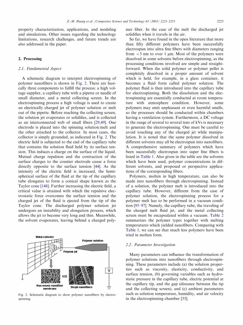
A schematic diagram to interpret electrospinning ofpolymer nanofibers is shown in Fig. 2. There are basi-cally three components to fulfill the process: a high vol-tage supplier, a capillary tube with a pipette or needle ofsmall diameter, and a metal collecting screen. In theelectrospinning process a high voltage is used to createan electrically charged jet of polymer solution or meltout of the pipette. Before reaching the collecting screen,the solution jet evaporates or solidifies, and is collectedas an interconnected web of small fibers [29,49]. Oneelectrode is placed into the spinning solution/melt andthe other attached to the collector. In most cases, thecollector is simply grounded, as indicated in Fig. 2. Theelectric field is subjected to the end of the capillary tubethat contains the solution fluid held by its surface ten-sion. This induces a charge on the surface of the liquid.Mutual charge repulsion and the contraction of thesurface charges to the counter electrode cause a forcedirectly opposite to the surface tension [44]. As theintensity of the electric field is increased, the hemi-spherical surface of the fluid at the tip of the capillarytube elongates to form a conical shape known as theTaylor cone [148]. Further increasing the electric field, acritical value is attained with which the repulsive elec-trostatic force overcomes the surface tension and thecharged jet of the fluid is ejected from the tip of theTaylor cone. The discharged polymer solution jetundergoes an instability and elongation process, whichallows the jet to become very long and thin. Meanwhile,the solvent evaporates, leaving behind a charged poly-
mer fiber. In the case of the melt the discharged jetsolidifies when it travels in the air.So far, we have found in the open literature that more
than fifty different polymers have been successfullyelectrospun into ultra fine fibers with diameters rangingfrom <3 nm to over 1 mm. Most of the polymers weredissolved in some solvents before electrospinning, as theprocessing conditions involved are simple and straight-forward. When the solid polymer or polymer pellet iscompletely dissolved in a proper amount of solventwhich is held, for example, in a glass container, itbecomes a fluid form called polymer solution. Thepolymer fluid is then introduced into the capillary tubefor electrospinning. Both the dissolution and the elec-trospinning are essentially conducted at room tempera-ture with atmosphere condition. However, somepolymers may emit unpleasant or even harmful smells,so the processes should be conducted within chambershaving a ventilation system. Furthermore, a DC voltagein the range of several to several tens of kVs is necessaryto generate the electrospinning. One must be careful toavoid touching any of the charged jet while manipu-lation. It is noted that the same polymer dissolved indifferent solvents may all be electrospun into nanofibers.A comprehensive summary of polymers which havebeen successfully electrospun into super fine fibers islisted in Table 1. Also given in the table are the solventswhich have been used, polymer concentrations in dif-ferent solvents, and proposed or perspective applica-tions of the corresponding fibers.Polymers, molten in high temperature, can also be
made into nanofibers through electrospinning. Insteadof a solution, the polymer melt is introduced into thecapillary tube. However, different from the case ofpolymer solution, the electrospinning process for apolymer melt has to be performed in a vacuum condi-tion [95–97]. Namely, the capillary tube, the traveling ofthe charged melt fluid jet, and the metal collectingscreen must be encapsulated within a vacuum. Table 2summarizes the polymer types together with meltingtemperatures which yielded nanofibers. Comparing withTable 1, we can see that much less polymers have beentried in molten form.
2.2. Parameter Investigation
Many parameters can influence the transformation ofpolymer solutions into nanofibers through electrospin-ning. These parameters include (a) the solution proper-ties such as viscosity, elasticity, conductivity, andsurface tension, (b) governing variables such as hydro-static pressure in the capillary tube, electric potential atthe capillary tip, and the gap (distance between the tipand the collecting screen), and (c) ambient parameterssuch as solution temperature, humidity, and air velocityin the electrospinning chamber [35].
Fig. 2. Schematic diagram to show polymer nanofibers by electro-
spinning.
Z.-M. Huang et al. / Composites Science and Technology 63 (2003) 2223–2253 2225
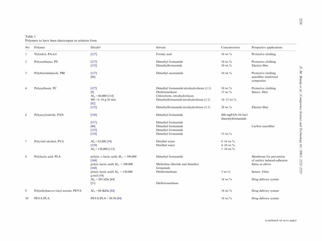
Table 1
Polymers to have been electrospun in solution form
No. Polymer Detailsa Solvent Co tion Perspective applications
1 Nylon6,6, PA-6,6 [127] Formic acid 10 Protective clothing
2 Polyurethanes, PU [127] Dimethyl formamide Protective clothing
[152] Dimethylformamide Electret filter
3 Polybenzimidazole, PBI [127] Dimethyl accetamide Protective clothing
[88] nanofiber reinforced
composites
4 Polycarboate, PC [127] Dimethyl formamide:tetrahydrofuran (1:1) Protective clothing
[9] Dichlormethane Sensor, filter
Mw=60,000 [114] Chloroform, tetrahydrofuran
MI=8–10 g/10 min
[92]
Dimethylformamide:tetrahydrofuran (1:1) –
[152] Dimethylformamide:tetrahydrofuran (1:1) Electret filter
6 Polyacrylonitrile, PAN [156] Dimethyl formamide 0 N/10-5m3
m rmamide
[157] Dimethyl formamide
[40] Dimethyl formamide Carbon nanofiber
[125] Dimethyl formamide
[158] Dimethyl formamide
7 Polyvinil alcohol, PVA Mn=65,000 [34] Distilled water 1
[129] Distilled water 1
Mn=150,000 [115] 1
8 Polylactic acid, PLA poly(d, l-lactic acid) Mw =109,000
[168]
Dimethyl formamide Membrane for prevention
of surfery induced-adhesion
poly(l-lactic acid) Mw =100,000
[168]
Methylene chloride and dimethyl
formamide
Sama as above
poly(l-lactic acid) Mn =150,000
g/mol [10]
Dichlormethane w Sensor, Filter
Mw=205 kDa [84] Drug delivery system
[21] Dichloromethane
9 Polyethylene-co-vinyl acetate, PEVA Mw=60.4kDa [84] Drug delivery system
10 PEVA/PLA PEVA/PLA=50/50 [84] Drug delivery system
(continued on next page)
2226
Z.-M
.Huangetal./Composites
Scien
ceandTechnology63(2003)2223–2253
10
10
10
10
15
14
20
60
di
15
8–
4–
1–
5
14
14
14
ncentra
wt.%
wt.%
wt.%
wt.%
wt.%
wt.%
15 wt.%
wt.%
mgPA
ethylfo
wt.%
6 wt.%
0 wt.%
0 wt.%
t.%
wt.%
wt.%
wt.%
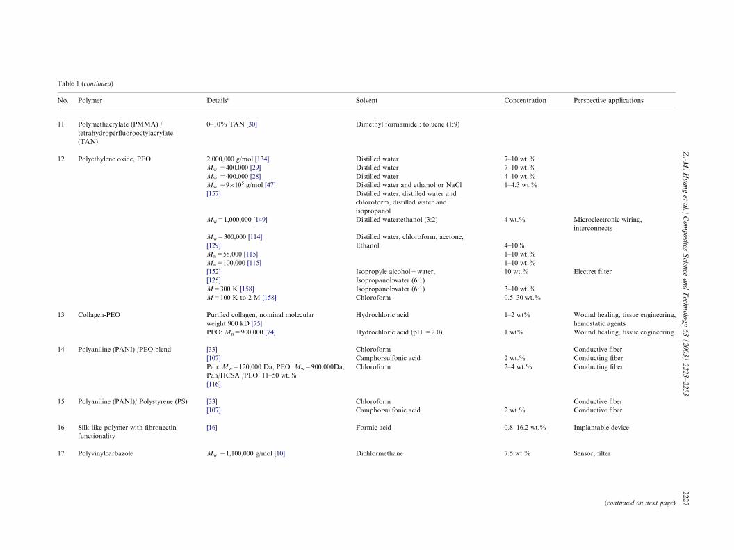
Table 1 (continued)
No. Polymer Detailsa Solvent Co tion Perspective applications
11 Polymethacrylate (PMMA) /
tetrahydroperfluorooctylacrylate
(TAN)
0–10% TAN [30] Dimethyl formamide : toluene (1:9)
12 Polyethylene oxide, PEO 2,000,000 g/mol [134] Distilled water 1
Mw =400,000 [29] Distilled water 1
Mw =400,000 [28] Distilled water 1
Mw =9�105 g/mol [47] Distilled water and ethanol or NaCl 4
[157] Distilled water, distilled water and
chloroform, distilled water and
isopropanol
Mw=1,000,000 [149] Distilled water:ethanol (3:2) w Microelectronic wiring,
interconnects
Mw=300,000 [114] Distilled water, chloroform, acetone,
[129] Ethanol 1
Mn=58,000 [115] 1
Mn=100,000 [115] 1
[152] Isopropyle alcohol+water, Electret filter
[125] Isopropanol:water (6:1)
M=300 K [158] Isopropanol:water (6:1) 1
M=100 K to 2 M [158] Chloroform 5 %
13 Collagen-PEO Purified collagen, nominal molecular
weight 900 kD [75]
Hydrochloric acid 2 Wound healing, tissue engineering,
hemostatic agents
PEO: Mn=900,000 [74] Hydrochloric acid (pH =2.0) w Wound healing, tissue engineering
14 Polyaniline (PANI) /PEO blend [33] Chloroform Conductive fiber
[107] Camphorsulfonic acid w Conducting fiber
Pan:Mw=120,000 Da, PEO: Mw=900,000Da,
Pan/HCSA /PEO: 11–50 wt.%
[116]
Chloroform 4 Conducting fiber
15 Polyaniline (PANI)/ Polystyrene (PS) [33] Chloroform Conductive fiber
[107] Camphorsulfonic acid w Conductive fiber
16 Silk-like polymer with fibronectin
functionality
[16] Formic acid 8 t.% Implantable device
17 Polyvinylcarbazole Mw =1,100,000 g/mol [10] Dichlormethane 5 Sensor, filter
(continued on next page)
Z.-M
.Huangetal./Composites
Scien
ceandTechnology63(2003)2223–2253
2227
7–
7–
4–
1–
4
4–
1–
1–
10
3–
0.
1–
1
2
2–
2
0.
7.
ncentra
0 wt.%
0 wt.%
0 wt.%
.3 wt.%
t.%
0%
0 wt.%
0 wt.%
wt.%
0 wt.%
–30 wt.
wt%
t%
t.%
wt.%
t.%
–16.2 w
wt.%
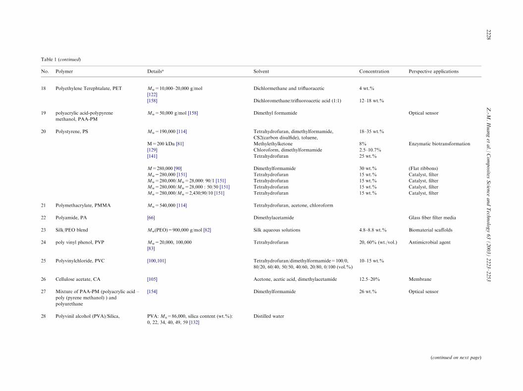
Table 1 (continued)
No. Polymer Detailsa Solvent Co tion Perspective applications
18 Polyethylene Terephtalate, PET Mw=10,000–20,000 g/mol
[122]
Dichlormethane and trifluoracetic 4 w
[158] Dichloromethane:trifluoroacetic acid (1:1) –
19 polyacrylic acid-polypyrene
methanol, PAA-PM
Mw=50,000 g/mol [158] Dimethyl formamide Optical sensor
20 Polystyrene, PS Mw=190,000 [114] Tetrahydrofuran, dimethylformamide,
CS2(carbon disulfide), toluene,
–
M=200 kDa [81] Methylethylketone Enzymatic biotransformation
[129] Chloroform, dimethylformamide 5
[141] Tetrahydrofuran
M=280,000 [90] Dimethylformamide (Flat ribbons)
Mw=280,000 [151] Tetrahydrofuran Catalyst, filter
Mw=280,000/Mw=28,000: 90/1 [151] Tetrahydrofuran Catalyst, filter
Mw=280,000/Mw=28,000 : 50/50 [151] Tetrahydrofuran Catalyst, filter
Mw=280,000/Mw=2,430;90/10 [151] Tetrahydrofuran Catalyst, filter
21 Polymethacrylate, PMMA Mw=540,000 [114] Tetrahydrofuran, acetone, chloroform
22 Polyamide, PA [66] Dimethylacetamide Glass fiber filter media
23 Silk/PEO blend Mw(PEO)=900,000 g/mol [82] Silk aqueous solutions 8 .% Biomaterial scaffolds
24 poly vinyl phenol, PVP Mw=20,000, 100,000
[83]
Tetrahydrofuran , t./vol.) Antimicrobial agent
25 Polyvinylchloride, PVC [100,101] Tetrahydrofuran/dimethylformamide=100/0,
80/20, 60/40, 50/50, 40/60, 20/80, 0/100 (vol.%)
–
26 Cellulose acetate, CA [105] Acetone, acetic acid, dimethylacetamide . Membrane
27 Mixture of PAA-PM (polyacrylic acid –
poly (pyrene methanol) ) and
polyurethane
[154] Dimethylformamide Optical sensor
28 Polyvinil alcohol (PVA)/Silica, PVA: Mn=86,000, silica content (wt.%):
0, 22, 34, 40, 49, 59 [132]
Distilled water
(continued on next page)
2228
Z.-M
.Huangetal./Composites
Scien
ceandTechnology63(2003)2223–2253
12
18
8%
2.
25
30
15
15
15
15
4.
20
10
12
26
ncentra
t.%
18 wt.%
35 wt.%
–10.7%
wt.%
wt.%
wt.%
wt.%
wt.%
wt.%
–8.8 wt
60% (w
15 wt.%
5–20%
wt.%
Table 1 (continued)
No. Polymer Detailsa Solvent Co tion Perspective applications
29 Polyacrylamide, PAAm Mn=5,000,000 [115] 1–1
30 PLGA PLGA(PLA/PGA)=(85/15) [102] Tetrahydrofuran:dimethylformamide (1:1) 1 g Scaffold for tissue engineering
31 Collagen [113] Hexafluoro-2-propanol Scaffold for tissue engineering
32 Polycaprolactone, PCL [125] Chloroform:methanol (3:1) toluene:methanol
(1:1), and dichloromethane:methanol (3:1)
33 Poly(2-hydroxyethyl methacrylate),
HEMA
M=200,000 [90] Ethanol:formic acid (1:1), ethanol 12, /
8, t.%
(Flat ribbons)
34 Poly(vinylidene fluoride) , PVDF M=107,000 [90] Dimethylformamide:dimethylacetamide (1/1) 20 (Flat ribbons)
35 Polyether imide, PEI [90] Hexafluoro-2-propanol 10 (Flat ribbons)
36 Polyethylene gricol, PEG M=10 K [158] Chloroform 0.5 %
37 nylon-4,6, PA-4,6 [7] Formic acid 10 Transparent composite
38 Poly(ferrocenyldimethylsilane), PFDMS Mw=87,000 g/mol [22] Tetrahydrofuran:dimethylformamide (9:1) 30
39 Nylon6 (PA-6) /montmorillonnite (Mt) Mt content=7.5 wt.% [50] Hexa-fluoro-isopropanol (HFIP),
HFIP/dimethylformamide: 95/5 (wt%)
10
40 poly(ethylene-co-vinyl alcohol) Vinyl alcohol repeat unit: 56–71 mol%
[85]
Isopropanol/water: 70/30 (%v/v) 2.5 /v Biomedical
41 Polyacrylnitrile (PAN) / TiO2 [168] Photovoltaic and
conductive polymers
42 Polycaprolactone (PCL) / metal Metals: gold, ZnO, [124] ZnO: cosmetic use
43 Polyvinyl pyrrolidone, PVP [26]
44 Polymetha-phenylene isophthalamide [124]
a Details possibly include: (a) reference, (b) molecular weight, and (c) content of each polymer in co-polymer/blend/composite.
Z.-M
.Huangetal./Composites
Scien
ceandTechnology63(2003)2223–2253
2229
ncentra
0 wt.%
/20 ml
20 wt.%
16, 20 w
wt.%,
wt.%
–30 wt.
wt.%
wt.%
wt.%
–20%w
Several researchers investigated spinnibility of differentpolymers. For instance, [47] found for electrospinningof aqueous poly(ethylene oxide) (PEO) dissolved inethanol-to-water solutions that viscosities in the rangeof 1–20 poises and surface tension between 35 and 55dynes/cm were suitable for fiber formation. At viscos-ities above 20 poises, electrospinning was prohibitedbecause of the instability of flow caused by the highcohesiveness of the solution. Droplets were formedwhen the viscosity was too low (<1 poise). Similarly,for electrospinning of cellulose acetate (CA) in 2:1 ace-tone/DMAc (dimethylacetamide), [105] recognized thatviscosities between 1.2 and 10.2 poises were applicable.Outside that range, the CA solutions could not be elec-trospun into fibers at room temperature. Namely, eitheronly few fibers could be obtained from a even higherviscosity solution or the fluid jet broke up to dropletsdue to too low viscosity (<1.2 poise). These twoexamples clearly demonstrated that the viscosity rangeof a different polymer solution which is spinnable isdifferent.As long as a polymer can be electrospun into nanofi-
bers, ideal targets would be in that: (1) the diameters ofthe fibers be consistent and controllable, (2) the fibersurface be defect-free or defect-controllable, and (3)continuous single nanofibers be collectable. However,researches so far have shown that there three targets areby no means easily achievable.One of the most important quantities related with
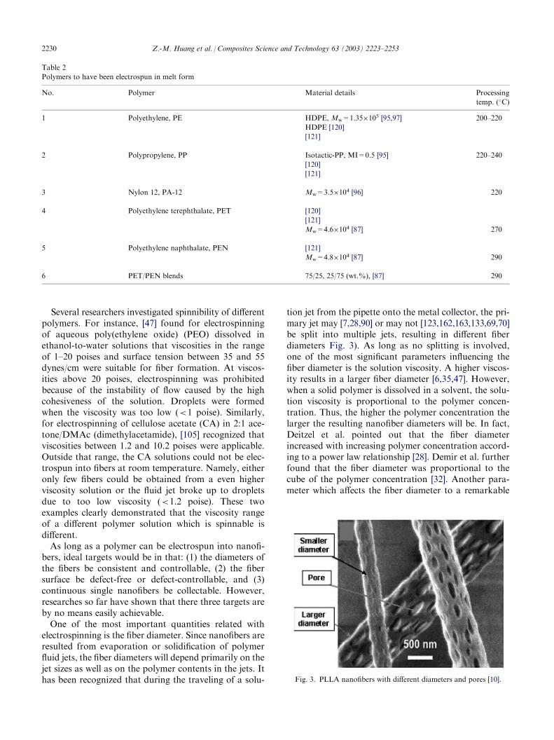
electrospinning is the fiber diameter. Since nanofibers areresulted from evaporation or solidification of polymerfluid jets, the fiber diameters will depend primarily on thejet sizes as well as on the polymer contents in the jets. Ithas been recognized that during the traveling of a solu-
tion jet from the pipette onto the metal collector, the pri-mary jet may [7,28,90] or may not [123,162,163,133,69,70]be split into multiple jets, resulting in different fiberdiameters Fig. 3). As long as no splitting is involved,one of the most significant parameters influencing thefiber diameter is the solution viscosity. A higher viscos-ity results in a larger fiber diameter [6,35,47]. However,when a solid polymer is dissolved in a solvent, the solu-tion viscosity is proportional to the polymer concen-tration. Thus, the higher the polymer concentration thelarger the resulting nanofiber diameters will be. In fact,Deitzel et al. pointed out that the fiber diameterincreased with increasing polymer concentration accord-ing to a power law relationship [28]. Demir et al. furtherfound that the fiber diameter was proportional to thecube of the polymer concentration [32]. Another para-meter which affects the fiber diameter to a remarkable
Table 2
Polymers to have been electrospun in melt form
No.
Polymer Material details Processingtemp. (�C)
1
Polyethylene, PE HDPE, Mw=1.35�105 [95,97] 200–220HDPE [120]
[121]
2
Polypropylene, PP Isotactic-PP, MI=0.5 [95] 220–240[120]
[121]
3
Nylon 12, PA-12 Mw=3.5�104 [96] 2204
Polyethylene terephthalate, PET [120][121]
Mw=4.6�104 [87]
2705
Polyethylene naphthalate, PEN [121]Mw=4.8�104 [87]
2906
PET/PEN blends 75/25, 25/75 (wt.%), [87] 290Fig. 3. PLLA nanofibers with different diameters and pores [10].
2230 Z.-M. Huang et al. / Composites Science and Technology 63 (2003) 2223–2253
extent is the applied electrical voltage. In general, ahigher applied voltage ejects more fluid in a jet, resultingin a larger fiber diameter [32].Further challenge with current electrospinning lies in
the fact that the fiber diameters obtained are seldomuniform. Not many reports have been given towardsresolving this problem. A useful attempt was recentlymade by [32]. While electrospinning polyurethanenanofibers, they recognized that the fiber diametersobtained from the polymer solution at a high (70 �C)temperature were much more uniform than those atroom temperature. The mechanisms involved, however,were not fully understood. It should be noted that theviscosity of the polyurethane solution with the sameconcentration at some higher temperature was sig-nificantly lower than that at room temperature. Thehighest polymer concentration which could be electro-spun into fibers was 12.8 wt.% at room temperature,whereas the concentration done at the high temperaturewas 21.2 wt.%. Unfortunately, Demir et al. did notcompare the viscosity values of the two concentrationsolutions which were electrospun at two different tem-peratures.Another problem encountered in electrospinning is
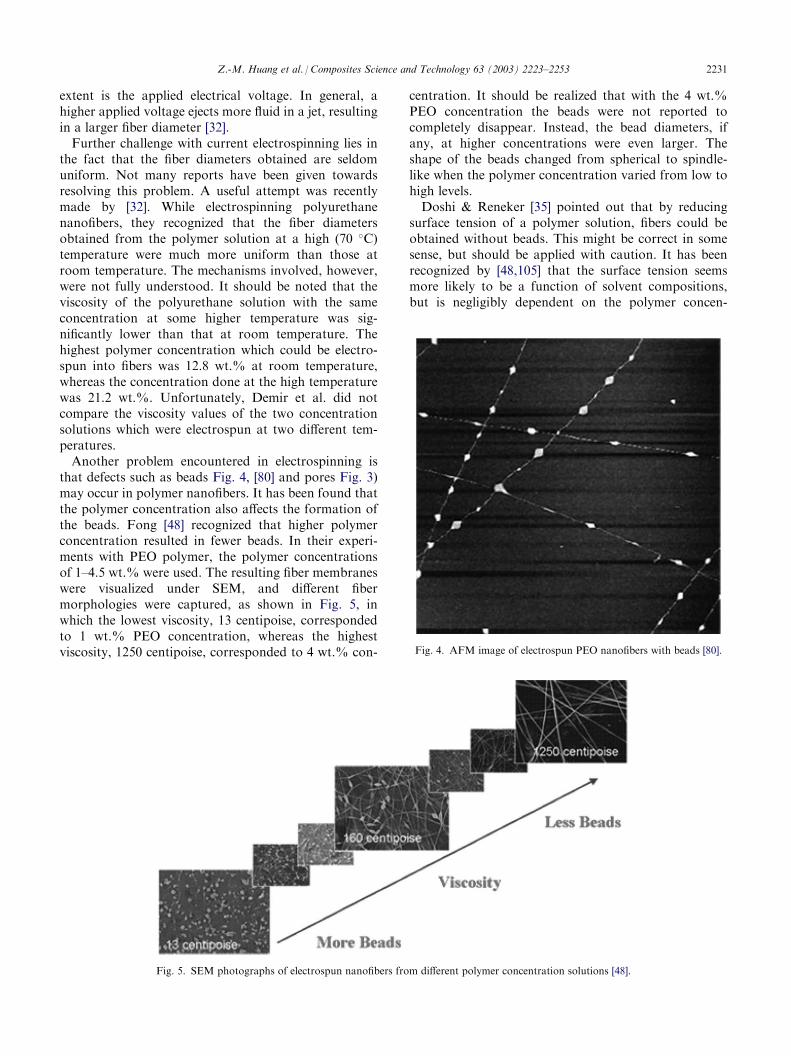
that defects such as beads Fig. 4, [80] and pores Fig. 3)may occur in polymer nanofibers. It has been found thatthe polymer concentration also affects the formation ofthe beads. Fong [48] recognized that higher polymerconcentration resulted in fewer beads. In their experi-ments with PEO polymer, the polymer concentrationsof 1–4.5 wt.% were used. The resulting fiber membraneswere visualized under SEM, and different fibermorphologies were captured, as shown in Fig. 5, inwhich the lowest viscosity, 13 centipoise, correspondedto 1 wt.% PEO concentration, whereas the highestviscosity, 1250 centipoise, corresponded to 4 wt.% con-
centration. It should be realized that with the 4 wt.%PEO concentration the beads were not reported tocompletely disappear. Instead, the bead diameters, ifany, at higher concentrations were even larger. Theshape of the beads changed from spherical to spindle-like when the polymer concentration varied from low tohigh levels.Doshi & Reneker [35] pointed out that by reducing
surface tension of a polymer solution, fibers could beobtained without beads. This might be correct in somesense, but should be applied with caution. It has beenrecognized by [48,105] that the surface tension seemsmore likely to be a function of solvent compositions,but is negligibly dependent on the polymer concen-
Fig. 4. AFM image of electrospun PEO nanofibers with beads [80].
Fig. 5. SEM photographs of electrospun nanofibers from different polymer concentration solutions [48].
Z.-M. Huang et al. / Composites Science and Technology 63 (2003) 2223–2253 2231
tration. Different solvents may contribute different sur-face tensions. However, not necessarily a lower surfacetension of a solvent will always be more suitable forelectrospinning. In their work with CA (cellulose ace-tate) polymer, Liu & Hsieh chose acetone, dimethylace-tamide (DMAc), and mixture of both as solvents. Theacetone used had a surface tension value of 23.7 dyne/cm lower than that of the DMAc, which was 32.4 dyne/cm. While no fibers but only beads were obtained fromusing theDMAc solvent alone, the electrospinning of 5 and8 wt.%CA in acetone also showed to generate short fiberswith diameters around 1 mm and a ‘‘beads on the string’’morphology. However, by using the mixture solvent with aratio of 2 (acetone) to 1 (DMAc), Liu & Hsieh yielded CAnanofibers free of beads in a range of concentrations 15–25wt.%. In a solvent of 10:1 acetone: DMAc, a 15 wt.% CAsolution generated fibers with very smooth surfaces anduniform diameters around 700 nm [105].Furthermore, adding some filler material into a poly-
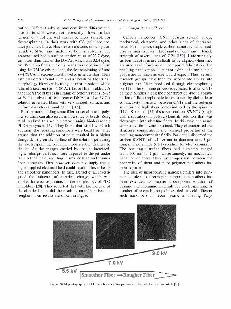
mer solution can also result in fibers free of beads. Zonget al. realized this while electrospinning biodegradablePLDA polymers [169]. They found that with 1 wt.% saltaddition, the resulting nanofibers were bead-free. Theyargued that the addition of salts resulted in a highercharge density on the surface of the solution jet duringthe electrospinning, bringing more electric charges tothe jet. As the charges carried by the jet increased,higher elongation forces were imposed to the jet underthe electrical field, resulting in smaller bead and thinnerfiber diameters. This, however, does not imply that ahigher applied electrical field could result in fewer beadsand smoother nanofibers. In fact, Deitzel et al. investi-gated the influence of electrical charge, which wasapplied for electrospinning, on the morphology of PEOnanofibers [28]. They reported that with the increase ofthe electrical potential the resulting nanofibers becamerougher. Their results are shown in Fig. 6.
2.3. Composite nanofibers
Carbon nanotubes (CNT) possess several uniquemechanical, electronic, and other kinds of character-istics. For instance, single carbon nanotube has a mod-ulus as high as several thousands of GPa and a tensilestrength of several tens of GPa [150]. Unfortunately,carbon nanotubes are difficult to be aligned when theyare used as reinforcement in composite fabrication. Theresulting nanocomposite cannot exhibit the mechanicalproperties as much as one would expect. Thus, severalresearch groups have tried to incorporate CNTs intopolymer nanofibers produced through electrospinning[89,119]. The spinning process is expected to align CNTsor their bundles along the fiber direction due to combi-nation of dielectrophoretic forces caused by dielectric orconductivity mismatch between CNTs and the polymersolution and high shear forces induced by the spinning[119]. Ko et al. [89] dispersed carbon SWNTs (singlewall nanotubes) in polyacrylonitrile solution that waselectrospun into ultrafine fibers. In this way, the nano-composite fibrils were obtained. They characterized thestructure, composition, and physical properties of theresulting nanocomposite fibrils. Park et al. dispersed thecarbon SWNTs of 1.2–1.6 nm in diameter and 3 mmlong in a polyimide (CP2) solution for electrospinning.The resulting ultrafine fibers had diameters rangedfrom 500 nm to 2 mm. Unfortunately, no mechanicalbehavior of these fibers or comparison between theproperties of them and pure polymer nanofibers hasbeen reported.The idea of incorporating nanoscale fillers into poly-
mer solution to electrospin composite nanofibers hasbeen extended to prepare a composite solution oforganic and inorganic materials for electrospinning. Anumber of research groups have tried to yield differentsuch nanofibers in recent years, in making Poly-
Fig. 6. SEM photographs of PEO nanofibers electrospun under different electrical potentials [28].
2232 Z.-M. Huang et al. / Composites Science and Technology 63 (2003) 2223–2253
caprolactone/gold or ZnO [124], Polyacrylnitrile (PAN)/TiO2 [167], PVA/Silica [132], and Nylon6/montmor-illonite (Mt) [50] ultrafine fibers, respectively. It deservesspecial mentioning that a significant effort was madevery recently by [27] who used sol-gel processing andelectrospinning technique to prepare alumina-borate/PVA composite nanofibers. These fibers were then cal-cined at above 1000 �C into alumina-borate ultrafinefibers. In their processing, the aqueous PVA solutionwas first prepared by dissolving PVA powder in distilledwater, which was then added to the aluminium acetatestabilized with boric acid. The mixture solution waselectrospun into the alumina-borate/PVA compositenanofibers. It was found that at temperatures higherthan 1000 �C the PVA decomposed, leaving the alu-mina-borate alone. In this way, the continuous (non-woven) ceramic ultrafine fibers were obtained. Evi-dently, the technique needs to be extensively explored sothat other kinds of ceramic or metal nanofibers can beprepared through electrospinning.
2.4. Fiber alignment
Most nanofibers obtained so far are in non-wovenform, which can be useful for relatively small number ofapplications such as filtration [3,60], tissue scaffolds [46],implant coating film [16], and wound dressing [82].However, as we understand from traditional fiber andtextile industry, only when continuous single nanofibersor uniaxial fiber bundles are obtained can their applica-tions be expanded into unlimited. Nevertheless, this is avery tough target to be achieved for electrospun nano-fibers, because the polymer jet trajectory is in a verycomplicated three-dimensional ‘‘whipping’’ way causedby bending instability rather than in a straight line.Efforts are believed to be being made in various researchgroups all over the world. Up to date, however, there isno continuous long nanofiber yarn obtained and thepublications related to aligned nanofibers are very lim-ited. Following five techniques are some possible meanswhich have been attempted to align electrospun nanofi-bers.
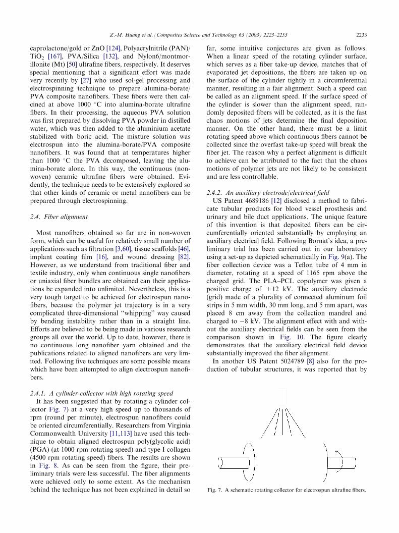
2.4.1. A cylinder collector with high rotating speedIt has been suggested that by rotating a cylinder col-
lector Fig. 7) at a very high speed up to thousands ofrpm (round per minute), electrospun nanofibers couldbe oriented circumferentially. Researchers from VirginiaCommonwealth University [11,113] have used this tech-nique to obtain aligned electrospun poly(glycolic acid)(PGA) (at 1000 rpm rotating speed) and type I collagen(4500 rpm rotating speed) fibers. The results are shownin Fig. 8. As can be seen from the figure, their pre-liminary trials were less successful. The fiber alignmentswere achieved only to some extent. As the mechanismbehind the technique has not been explained in detail so
far, some intuitive conjectures are given as follows.When a linear speed of the rotating cylinder surface,which serves as a fiber take-up device, matches that ofevaporated jet depositions, the fibers are taken up onthe surface of the cylinder tightly in a circumferentialmanner, resulting in a fair alignment. Such a speed canbe called as an alignment speed. If the surface speed ofthe cylinder is slower than the alignment speed, ran-domly deposited fibers will be collected, as it is the fastchaos motions of jets determine the final depositionmanner. On the other hand, there must be a limitrotating speed above which continuous fibers cannot becollected since the overfast take-up speed will break thefiber jet. The reason why a perfect alignment is difficultto achieve can be attributed to the fact that the chaosmotions of polymer jets are not likely to be consistentand are less controllable.
2.4.2. An auxiliary electrode/electrical fieldUS Patent 4689186 [12] disclosed a method to fabri-
cate tubular products for blood vessel prosthesis andurinary and bile duct applications. The unique featureof this invention is that deposited fibers can be cir-cumferentially oriented substantially by employing anauxiliary electrical field. Following Bornat’s idea, a pre-liminary trial has been carried out in our laboratoryusing a set-up as depicted schematically in Fig. 9(a). Thefiber collection device was a Teflon tube of 4 mm indiameter, rotating at a speed of 1165 rpm above thecharged grid. The PLA–PCL copolymer was given apositive charge of +12 kV. The auxiliary electrode(grid) made of a plurality of connected aluminum foilstrips in 5 mm width, 30 mm long, and 5 mm apart, wasplaced 8 cm away from the collection mandrel andcharged to �8 kV. The alignment effect with and with-out the auxiliary electrical fields can be seen from thecomparison shown in Fig. 10. The figure clearlydemonstrates that the auxiliary electrical field devicesubstantially improved the fiber alignment.In another US Patent 5024789 [8] also for the pro-
duction of tubular structures, it was reported that by
Fig. 7. A schematic rotating collector for electrospun ultrafine fibers.
Z.-M. Huang et al. / Composites Science and Technology 63 (2003) 2223–2253 2233
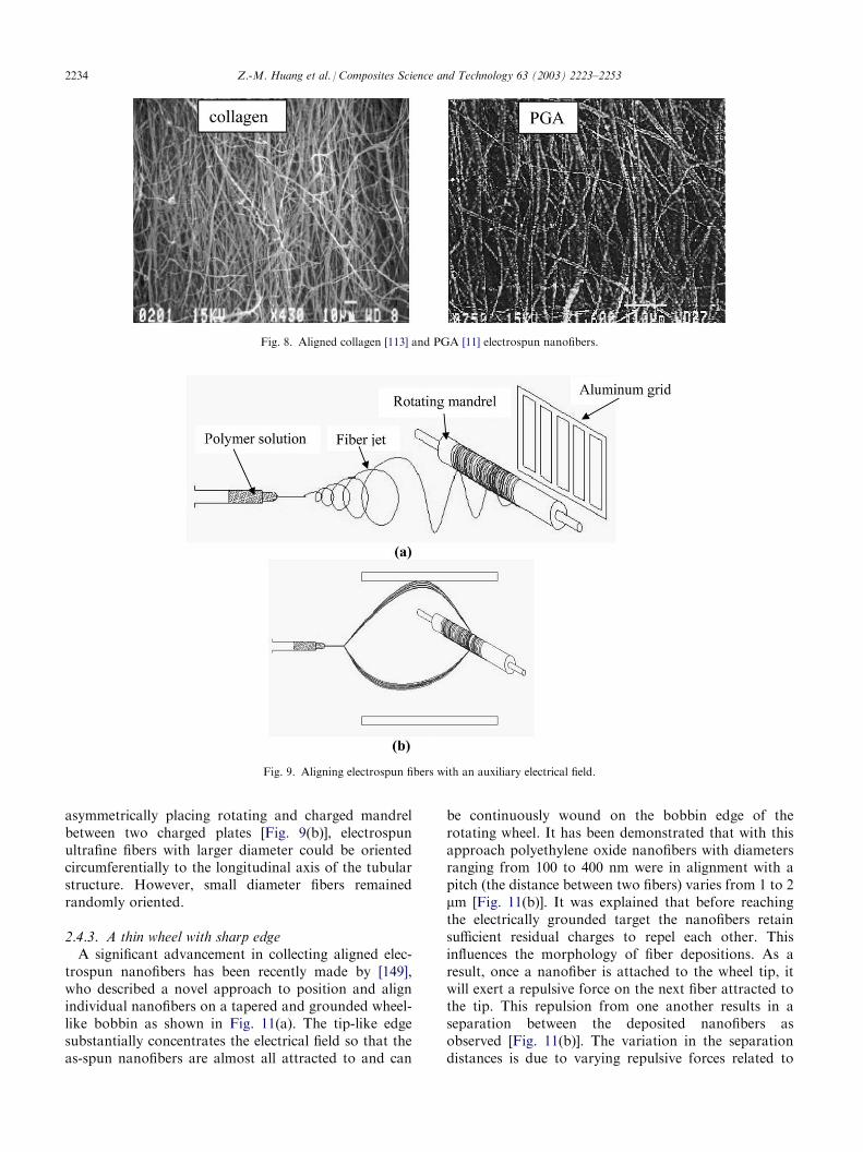
asymmetrically placing rotating and charged mandrelbetween two charged plates [Fig. 9(b)], electrospunultrafine fibers with larger diameter could be orientedcircumferentially to the longitudinal axis of the tubularstructure. However, small diameter fibers remainedrandomly oriented.
2.4.3. A thin wheel with sharp edgeA significant advancement in collecting aligned elec-
trospun nanofibers has been recently made by [149],who described a novel approach to position and alignindividual nanofibers on a tapered and grounded wheel-like bobbin as shown in Fig. 11(a). The tip-like edgesubstantially concentrates the electrical field so that theas-spun nanofibers are almost all attracted to and can
be continuously wound on the bobbin edge of therotating wheel. It has been demonstrated that with thisapproach polyethylene oxide nanofibers with diametersranging from 100 to 400 nm were in alignment with apitch (the distance between two fibers) varies from 1 to 2mm [Fig. 11(b)]. It was explained that before reachingthe electrically grounded target the nanofibers retainsufficient residual charges to repel each other. Thisinfluences the morphology of fiber depositions. As aresult, once a nanofiber is attached to the wheel tip, itwill exert a repulsive force on the next fiber attracted tothe tip. This repulsion from one another results in aseparation between the deposited nanofibers asobserved [Fig. 11(b)]. The variation in the separationdistances is due to varying repulsive forces related to
Fig. 9. Aligning electrospun fibers with an auxiliary electrical field.
Fig. 8. Aligned collagen [113] and PGA [11] electrospun nanofibers.
2234 Z.-M. Huang et al. / Composites Science and Technology 63 (2003) 2223–2253
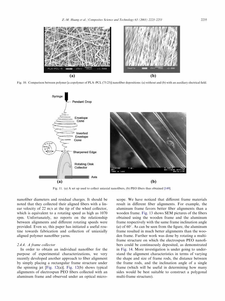
nanofiber diameters and residual charges. It should benoted that they collected their aligned fibers with a lin-ear velocity of 22 m/s at the tip of the wheel collector,which is equivalent to a rotating speed as high as 1070rpm. Unfortunately, no reports on the relationshipbetween alignments and different rotating speeds wereprovided. Even so, this paper has initiated a useful rou-tine towards fabrication and collection of uniaxiallyaligned polymer nanofiber yarns.
2.4.4. A frame collectorIn order to obtain an individual nanofiber for the
purpose of experimental characterizations, we veryrecently developed another approach to fiber alignmentby simply placing a rectangular frame structure underthe spinning jet [Fig. 12(a)]. Fig. 12(b) shows typicalalignments of electrospun PEO fibers collected with analuminum frame and observed under an optical micro-
scope. We have noticed that different frame materialsresult in different fiber alignments. For example, thealuminum frame favors better fiber alignments than awooden frame. Fig. 13 shows SEM pictures of the fibersobtained using the wooden frame and the aluminumframe respectively with the same frame inclination angle(�) of 60�. As can be seen from the figure, the aluminumframe resulted in much better alignments than the woo-den frame. Further work was done by rotating a multi-frame structure on which the electrospun PEO nanofi-bers could be continuously deposited, as demonstratedin Fig. 14. More investigation is under going to under-stand the alignment characteristics in terms of varyingthe shape and size of frame rods, the distance betweenthe frame rods, and the inclination angle of a singleframe (which will be useful in determining how manysides would be best suitable to construct a polygonalmulti-frame structure).
Fig. 10. Comparison between polymer [a copolymer of PLA–PCL (75:25)] nanofiber depositions: (a) without and (b) with an auxiliary electrical field.
Fig. 11. (a) A set up used to collect uniaxial nanofibers, (b) PEO fibers thus obtained [149].
Z.-M. Huang et al. / Composites Science and Technology 63 (2003) 2223–2253 2235
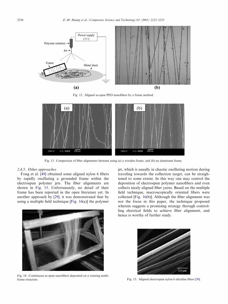
2.4.5. Other approachesFong et al. [49] obtained some aligned nylon 6 fibers
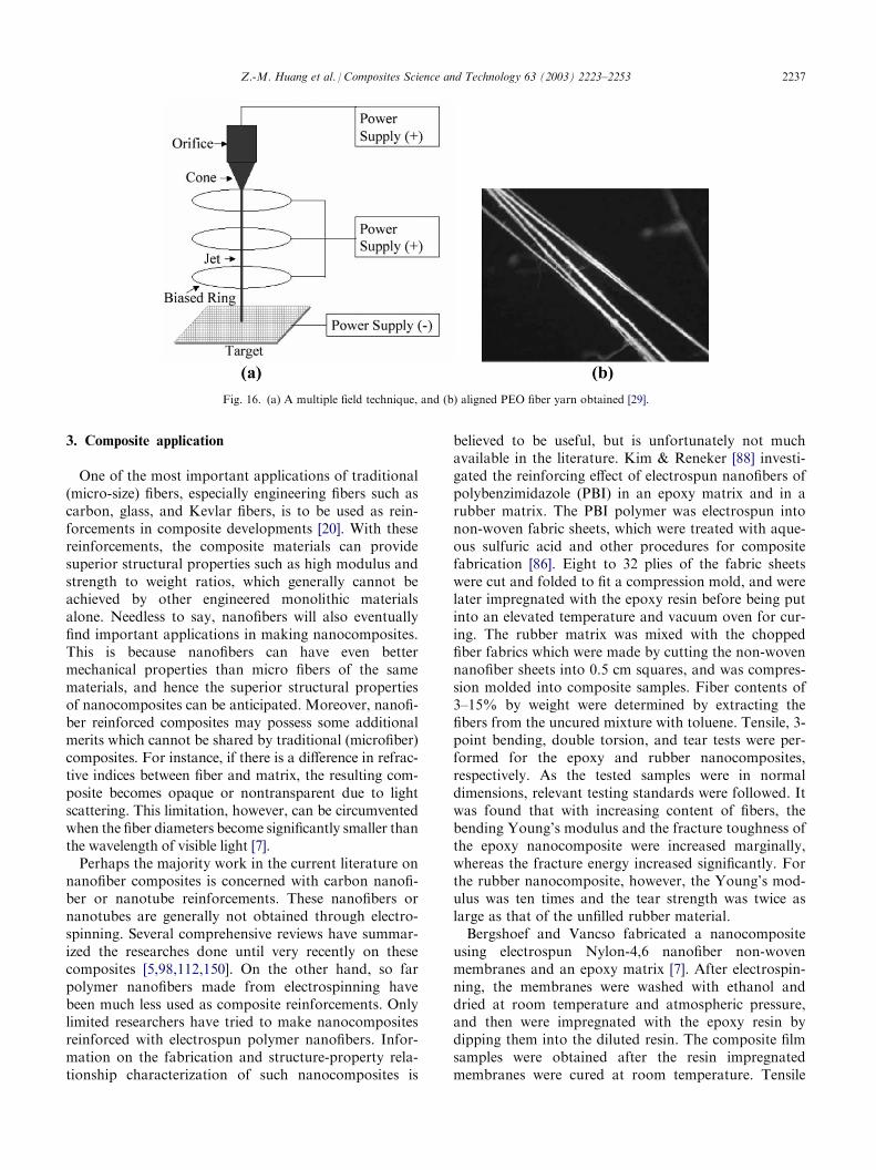
by rapidly oscillating a grounded frame within theelectrospun polymer jets. The fiber alignments areshown in Fig. 15. Unfortunately, no detail of theirframe has been reported in the open literature yet. Inanother approach by [29], it was demonstrated that byusing a multiple field technique [Fig. 16(a)] the polymer
jet, which is usually in chaotic oscillating motion duringtraveling towards the collection target, can be straigh-tened to some extent. In this way one may control thedeposition of electrospun polymer nanofibers and evencollects nicely aligned fiber yarns. Based on the multiplefield technique, macroscopically oriented fibers werecollected [Fig. 16(b)]. Although the fiber alignment wasnot the focus in this paper, the technique proposedwherein suggests a promising strategy through control-ling electrical fields to achieve fiber alignment, andhence is worthy of further study.
Fig. 12. Aligned as-spun PEO nanofibers by a frame method.
Fig. 13. Comparison of fiber alignments between using (a) a wooden frame, and (b) an aluminum frame.
Fig. 14. Continuous as-spun nanofibers deposited on a rotating multi-
frame structure.
Fig. 15. Aligned electrospun nylon 6 ultrafine fibers [50].2236 Z.-M. Huang et al. / Composites Science and Technology 63 (2003) 2223–2253
3. Composite application
One of the most important applications of traditional(micro-size) fibers, especially engineering fibers such ascarbon, glass, and Kevlar fibers, is to be used as rein-forcements in composite developments [20]. With thesereinforcements, the composite materials can providesuperior structural properties such as high modulus andstrength to weight ratios, which generally cannot beachieved by other engineered monolithic materialsalone. Needless to say, nanofibers will also eventuallyfind important applications in making nanocomposites.This is because nanofibers can have even bettermechanical properties than micro fibers of the samematerials, and hence the superior structural propertiesof nanocomposites can be anticipated. Moreover, nanofi-ber reinforced composites may possess some additionalmerits which cannot be shared by traditional (microfiber)composites. For instance, if there is a difference in refrac-tive indices between fiber and matrix, the resulting com-posite becomes opaque or nontransparent due to lightscattering. This limitation, however, can be circumventedwhen the fiber diameters become significantly smaller thanthe wavelength of visible light [7].Perhaps the majority work in the current literature on
nanofiber composites is concerned with carbon nanofi-ber or nanotube reinforcements. These nanofibers ornanotubes are generally not obtained through electro-spinning. Several comprehensive reviews have summar-ized the researches done until very recently on thesecomposites [5,98,112,150]. On the other hand, so farpolymer nanofibers made from electrospinning havebeen much less used as composite reinforcements. Onlylimited researchers have tried to make nanocompositesreinforced with electrospun polymer nanofibers. Infor-mation on the fabrication and structure-property rela-tionship characterization of such nanocomposites is
believed to be useful, but is unfortunately not muchavailable in the literature. Kim & Reneker [88] investi-gated the reinforcing effect of electrospun nanofibers ofpolybenzimidazole (PBI) in an epoxy matrix and in arubber matrix. The PBI polymer was electrospun intonon-woven fabric sheets, which were treated with aque-ous sulfuric acid and other procedures for compositefabrication [86]. Eight to 32 plies of the fabric sheetswere cut and folded to fit a compression mold, and werelater impregnated with the epoxy resin before being putinto an elevated temperature and vacuum oven for cur-ing. The rubber matrix was mixed with the choppedfiber fabrics which were made by cutting the non-wovennanofiber sheets into 0.5 cm squares, and was compres-sion molded into composite samples. Fiber contents of3–15% by weight were determined by extracting thefibers from the uncured mixture with toluene. Tensile, 3-point bending, double torsion, and tear tests were per-formed for the epoxy and rubber nanocomposites,respectively. As the tested samples were in normaldimensions, relevant testing standards were followed. Itwas found that with increasing content of fibers, thebending Young’s modulus and the fracture toughness ofthe epoxy nanocomposite were increased marginally,whereas the fracture energy increased significantly. Forthe rubber nanocomposite, however, the Young’s mod-ulus was ten times and the tear strength was twice aslarge as that of the unfilled rubber material.Bergshoef and Vancso fabricated a nanocomposite
using electrospun Nylon-4,6 nanofiber non-wovenmembranes and an epoxy matrix [7]. After electrospin-ning, the membranes were washed with ethanol anddried at room temperature and atmospheric pressure,and then were impregnated with the epoxy resin bydipping them into the diluted resin. The composite filmsamples were obtained after the resin impregnatedmembranes were cured at room temperature. Tensile
Fig. 16. (a) A multiple field technique, and (b) aligned PEO fiber yarn obtained [29].
Z.-M. Huang et al. / Composites Science and Technology 63 (2003) 2223–2253 2237
tests were conducted for the composite as well as themonolithic matrix films. It was reported that both thestiffness and strength of the composite were significantlyhigher than those of the reference matrix film althoughthe fiber content was low. It is noted that Bergshoef &Vancso determined the fiber content by using an ele-mental analysis and a thermal analysis. In the first ana-lysis, the nitrogen content of the pure fibers, thereinforced matrix, and the monolithic resin were deter-mined. Assuming weight additivity, the fiber content inthe composite thus obtained was 3.9% by weight. In theother analysis, the melt enthalpy of the nylon used inthe composite was determined by DSC, which yielded afiber weight fraction of 4.6%.In addition to the stiffness and strength improve-
ment, researchers also tried to modify other mechanicalbehavior of composites by using electrospun ultrafinepolymer fibers. For instance, the very high surface tovolume ratio of these fibers may be suitable for theimprovement of the interlaminar toughness of a highperformance composite laminate, which is an impor-tant issue in applications. A US patent was recentlyissued to Dzenis & Reneker [39] who proposed usingpolymer nanofibers in between laminas of a laminate toimprove delamination resistance. They arranged PBInanofibers at the interfaces between plies of the lami-nate without a substantial reduction for the in-plainproperties and an increase in weight and/or ply thickness.It was reported that by incorporating electrospun PBInanofibers of 300–500 nm diameters in-between a uni-directional composites made of graphite/epoxy prepregsof T2G190/F263, Mode I critical energy release rate GIc
increased by 15%, while an increase of 130% in the ModeII critical energy release rate GIIc was observed.Up to date, the polymer composites reinforced with
electrospun nanofibers have been developed mainly forproviding some outstanding physical (e.g. optical andelectrical) and chemical properties while keeping theirappropriate mechanical performance. For instance, inthe report by [7], the epoxy composite with electrospunnylon 4,6 nanofibers of 30–200 nm diameters exhibiteda characteristic transparency due to the fiber sizessmaller than the wavelength of visible light. It is alsonoted that single wall carbon nanotube (SWNT) rein-forced polyimide composite in the form of nanofibrousfilm was made by electrospinning to explore a potentialapplication for spacecrafts [119]. Carbon nanofibers forcomposite applications can also be manufactured fromprecursor polymer nanofibers [24,40]. Such kind ofcontinuous carbon nanofiber composite also has poten-tial applications as filters for separation of small parti-cles from gas or liquid, supports for high temperaturecatalysts, heat management materials in aircraft andsemiconductor devices, as well as promising candidatesas small electronic devices, rechargeable batteries, andsupercapacitors [24].
Due to limited number of papers published in theopen literature, many important issues relevant tonanocomposites reinforced with electrospun polymernanofibers have essentially not been taken into accountyet. For instance, it is well known that the interfacebonding between a polymer fiber and a different poly-mer matrix is generally poor. How to modify thisbonding for polymer nanofiber polymer matrix compo-sites seems to have not been touched at all, althoughthere are a vast number of publications on this topic fortraditional fibrous composites in the literature. Fur-thermore, little work has been done on the modelingand simulation of the mechanical properties of nanofi-ber composites. Although many micromechanics mod-els have been developed for predicting the stiffness andstrength of fibrous composites [77], whether they arestill applicable to nanofiber composites needs to be ver-ified [64]. Compared with its counterpart for traditionalfibrous composites, one of the main barriers to theimplementation of such work for nanofiber compositesis that one does not know the mechanical behavior ofsingle polymer nanofibers.Several reasons can be attributed to the less develop-
ment of electrospun polymer nanofiber reinforced com-posites. First of all, not sufficient quantity of uniaxialand continuous nanofibers has been obtained and couldbe used as reinforcements. It is well known from com-posite theory and practice that the superior structuralproperties can be achieved only when fibers are arran-ged in pre-determined directions such as in unidirec-tional laminae, multidirectional laminates, woven orbraided fabric reinforced composites. To make thesecomposites, continuous fiber bundles are necessary. Thenon-woven or randomly arranged nanofiber mats, ascollected to date from electrospinning, generally cannotresult in a significant improvement in the mechanicalproperties of the composites with their reinforcement.Another reason may be that polymers yielding thesefibers are generally considered as less suitable for struc-tural enhancement. Although carbon nanofibers areprincipally achievable from post-processing of electro-spun precursor polymer nanofibers such as poly-acrylonitrile (PAN) nanofibers [23,40,156], these fibersseem to have not been obtained in large quantity ofcontinuous single yarns yet. Thus, extensive work bothfrom the standpoint of nanofiber composite science(fabrication, characterization, modeling and simulation)and from industrial base (applications) viewpoint isnecessary in the future.
4. Other applications
In addition to composite reinforcement, other appli-cation fields based on electrospun polymer nanofibershave been steadily extended especially in recent years.
2238 Z.-M. Huang et al. / Composites Science and Technology 63 (2003) 2223–2253
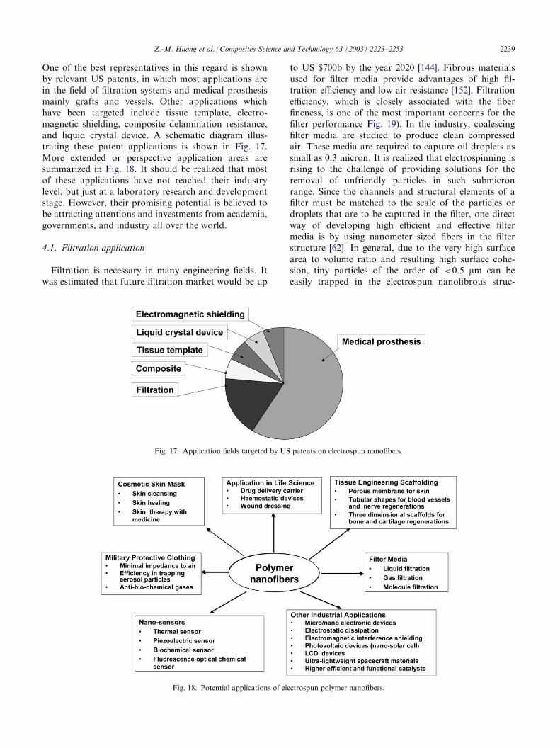
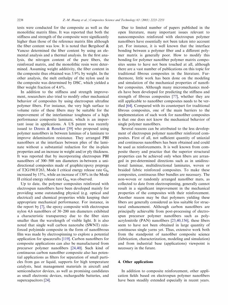
One of the best representatives in this regard is shownby relevant US patents, in which most applications arein the field of filtration systems and medical prosthesismainly grafts and vessels. Other applications whichhave been targeted include tissue template, electro-magnetic shielding, composite delamination resistance,and liquid crystal device. A schematic diagram illus-trating these patent applications is shown in Fig. 17.More extended or perspective application areas aresummarized in Fig. 18. It should be realized that mostof these applications have not reached their industrylevel, but just at a laboratory research and developmentstage. However, their promising potential is believed tobe attracting attentions and investments from academia,governments, and industry all over the world.
4.1. Filtration application
Filtration is necessary in many engineering fields. Itwas estimated that future filtration market would be up
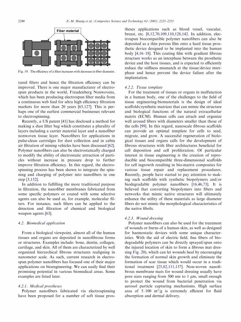
to US $700b by the year 2020 [144]. Fibrous materialsused for filter media provide advantages of high fil-tration efficiency and low air resistance [152]. Filtrationefficiency, which is closely associated with the fiberfineness, is one of the most important concerns for thefilter performance Fig. 19). In the industry, coalescingfilter media are studied to produce clean compressedair. These media are required to capture oil droplets assmall as 0.3 micron. It is realized that electrospinning isrising to the challenge of providing solutions for theremoval of unfriendly particles in such submicronrange. Since the channels and structural elements of afilter must be matched to the scale of the particles ordroplets that are to be captured in the filter, one directway of developing high efficient and effective filtermedia is by using nanometer sized fibers in the filterstructure [62]. In general, due to the very high surfacearea to volume ratio and resulting high surface cohe-sion, tiny particles of the order of <0.5 mm can beeasily trapped in the electrospun nanofibrous struc-
Fig. 17. Application fields targeted by US patents on electrospun nanofibers.
Fig. 18. Potential applications of electrospun polymer nanofibers.
Z.-M. Huang et al. / Composites Science and Technology 63 (2003) 2223–2253 2239
tured filters and hence the filtration efficiency can beimproved. There is one major manufacturer of electro-spun products in the world, Freudenberg Nonwovens,which has been producing electrospun filter media froma continuous web feed for ultra high efficiency filtrationmarkets for more than 20 years [65,127]. This is per-haps one of the earliest commercial businesses relevantto electrospinning.Recently, a US patent [41] has disclosed a method for
making a dust filter bag which constitutes a plurality oflayers including a carrier material layer and a nanofibernonwoven tissue layer. Nanofibers for applications inpulse-clean cartridges for dust collection and in cabinair filtration of mining vehicles have been discussed [62].Polymer nanofibers can also be electrostatically chargedto modify the ability of electrostatic attraction of parti-cles without increase in pressure drop to furtherimprove filtration efficiency. In this regard, the electro-spinning process has been shown to integrate the spin-ning and charging of polymer into nanofibers in onestep [3,152].In addition to fulfilling the more traditional purpose
in filtration, the nanofiber membranes fabricated fromsome specific polymers or coated with some selectiveagents can also be used as, for example, molecular fil-ters. For instance, such filters can be applied to thedetection and filtration of chemical and biologicalweapon agents [63].
4.2. Biomedical application
From a biological viewpoint, almost all of the humantissues and organs are deposited in nanofibrous formsor structures. Examples include: bone, dentin, collagen,cartilage, and skin. All of them are characterized by wellorganized hierarchical fibrous structures realigning innanometer scale. As such, current research in electro-spun polymer nanofibers has focused one of their majorapplications on bioengineering. We can easily find theirpromising potential in various biomedical areas. Someexamples are listed later.
4.2.1. Medical prosthesesPolymer nanofibers fabricated via electrospinning
have been proposed for a number of soft tissue pros-
theses applications such as blood vessel, vascular,breast, etc. [8,12,70,109,110,128,142. In addition, elec-trospun biocompatible polymer nanofibers can also bedeposited as a thin porous film onto a hard tissue pros-thetic device designed to be implanted into the humanbody [4,16–18]. This coating film with gradient fibrousstructure works as an interphase between the prostheticdevice and the host tissues, and is expected to efficientlyreduce the stiffness mismatch at the tissue/device inter-phase and hence prevent the device failure after theimplantation.
4.2.2. Tissue templateFor the treatment of tissues or organs in malfunction
in a human body, one of the challenges to the field oftissue engineering/biomaterials is the design of idealscaffolds/synthetic matrices that can mimic the structureand biological functions of the natural extracellurlarmatrix (ECM). Human cells can attach and organizewell around fibers with diameters smaller than those ofthe cells [99]. In this regard, nanoscale fibrous scaffoldscan provide an optimal template for cells to seed,migrate, and grow. A successful regeneration of biolo-gical tissues and organs calls for the development offibrous structures with fiber architectures beneficial forcell deposition and cell proliferation. Of particularinterest in tissue engineering is the creation of repro-ducible and biocompatible three-dimensional scaffoldsfor cell ingrowth resulting in bio-matrix composites forvarious tissue repair and replacement procedures.Recently, people have started to pay attention to mak-ing such scaffolds with synthetic biopolymers and/orbiodegradable polymer nanofibers [16,46,73]. It isbelieved that converting biopolymers into fibers andnetworks that mimic native structures will ultimatelyenhance the utility of these materials as large diameterfibers do not mimic the morphological characteristics ofthe native fibrils.
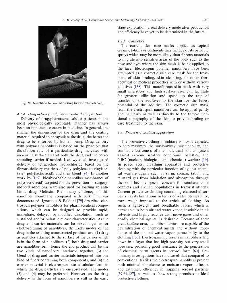
4.2.3. Wound dressingPolymer nanofibers can also be used for the treatment
of wounds or burns of a human skin, as well as designedfor haemostatic devices with some unique character-istics. With the aid of electric field, fine fibers of bio-degradable polymers can be directly sprayed/spun ontothe injured location of skin to form a fibrous mat dres-sing Fig. 20), which can let wounds heal by encouragingthe formation of normal skin growth and eliminate theformation of scar tissue which would occur in a tradi-tional treatment [25,82,111,137]. Non-woven nanofi-brous membrane mats for wound dressing usually havepore sizes ranging from 500 nm to 1 mm, small enoughto protect the wound from bacterial penetration viaaerosol particle capturing mechanisms. High surfacearea of 5–100 m2/g is extremely efficient for fluidabsorption and dermal delivery.
Fig. 19. The efficiency of a filter increases with decrease in fiber diameter.
2240 Z.-M. Huang et al. / Composites Science and Technology 63 (2003) 2223–2253
4.2.4. Drug delivery and pharmaceutical compositionDelivery of drug/pharmaceuticals to patients in the
most physiologically acceptable manner has alwaysbeen an important concern in medicine. In general, thesmaller the dimensions of the drug and the coatingmaterial required to encapsulate the drug, the better thedrug to be absorbed by human being. Drug deliverywith polymer nanofibers is based on the principle thatdissolution rate of a particulate drug increases withincreasing surface area of both the drug and the corre-sponding carrier if needed. Kenawy et al. investigateddelivery of tetracycline hydrochloride based on thefibrous delivery matrices of poly (ethylene-co-vinylace-tate), poly(lactic acid), and their blend [84]. In anotherwork by [169], bioabsorbable nanofiber membranes ofpoly(lactic acid) targeted for the prevention of surgery-induced adhesions, ware also used for loading an anti-biotic drug Mefoxin. Preliminary efficiency of thisnanofiber membrane compared with bulk film wasdemonstrated. Ignatious & Baldoni [79] described elec-trospun polymer nanofibers for pharmaceutical compo-sitions, which can be designed to provide rapid,immediate, delayed, or modified dissolution, such assustained and/or pulsatile release characteristics. As thedrug and carrier materials can be mixed together forelectrospinning of nanofibers, the likely modes of thedrug in the resulting nanostructed products are: (1) drugas particles attached to the surface of the carrier whichis in the form of nanofibers, (2) both drug and carrierare nanofiber-form, hence the end product will be thetwo kinds of nanofibers interlaced together, (3) theblend of drug and carrier materials integrated into onekind of fibers containing both components, and (4) thecarrier material is electrospun into a tubular form inwhich the drug particles are encapsulated. The modes(3) and (4) may be preferred. However, as the drugdelivery in the form of nanofibers is still in the early
stage exploration, a real delivery mode after productionand efficiency have yet to be determined in the future.
4.2.5. CosmeticsThe current skin care masks applied as topical
creams, lotions or ointments may include dusts or liquidsprays which may be more likely than fibrous materialsto migrate into sensitive areas of the body such as thenose and eyes where the skin mask is being applied tothe face. Electrospun polymer nanofibers have beenattempted as a cosmetic skin care mask for the treat-ment of skin healing, skin cleansing, or other ther-apeutical or medical properties with or without variousadditives [138]. This nanofibrous skin mask with verysmall interstices and high surface area can facilitatefar greater utilization and speed up the rate oftransfer of the additives to the skin for the fullestpotential of the additive. The cosmetic skin maskfrom the electrospun nanofibers can be applied gentlyand painlessly as well as directly to the three-dimen-sional topography of the skin to provide healing orcare treatment to the skin.
4.3. Protective clothing application
The protective clothing in military is mostly expectedto help maximize the survivability, sustainability, andcombat effectiveness of the individual soldier systemagainst extreme weather conditions, ballistics, andNBC (nuclear, biological, and chemical) warfare [19].In peace ages, breathing apparatus and protectiveclothing with the particular function of against chemi-cal warfare agents such as sarin, soman, tabun andmustard gas from inhalation and absorption throughthe skin become special concern for combatants inconflicts and civilian populations in terrorist attacks.Current protective clothing containing charcoal absor-bents has its limitations in terms of water permeability,extra weight-imposed to the article of clothing. Assuch, a lightweight and breathable fabric, which ispermeable to both air and water vapor, insoluble in allsolvents and highly reactive with nerve gases and otherdeadly chemical agents, is desirable. Because of theirgreat surface area, nanofiber fabrics are capable of theneutralization of chemical agents and without impe-dance of the air and water vapor permeability to theclothing [137]. Electrospinning results in nanofibers laiddown in a layer that has high porosity but very smallpore size, providing good resistance to the penetrationof chemical harm agents in aerosol form [60]. Pre-liminary investigations have indicated that compared toconventional textiles the electrospun nanofibers presentboth minimal impedance to moisture vapor diffusionand extremely efficiency in trapping aerosol particles[59,61,127], as well as show strong promises as idealprotective clothing.
Fig. 20. Nanofibers for wound dressing (www.electrosols.com).
Z.-M. Huang et al. / Composites Science and Technology 63 (2003) 2223–2253 2241
4.4. Electrical and optical application
Conductive nanofibers are expected to be used in thefabrication of tiny electronic devices or machines suchas Schottky junctions, sensors and actuators. Due to thewell-known fact that the rate of electrochemical reac-tions is proportional to the surface area of the electrode,conductive nanofibrous membranes are also quite sui-table for using as porous electrode in developing highperformance battery [116,166]. Conductive (in terms ofelectrical, ionic and photoelectric) membranes also havepotential for applications including electrostatic dis-sipation, corrosion protection, electromagnetic inter-ference shielding, photovoltaic device, etc. [130,131].Waters et al. [159] reported to use electrospun nano-
fibers in the development of a liquid crystal device ofoptical shutter which is switchable under an electric fieldbetween a state in which it is substantially transparentto incident light and a state in which it is substantiallyopaque. The main part of this liquid crystal device con-sisted of a layer of nanofibers permeated with a liquid-crystal material, having a thickness of only few tensmicrons. The layer was located between two electrodes,by means of which an electric field could be appliedacross the layer to vary the transmissivity of the liquidcrystal/nanofiber composite. It is the fiber size used thatdetermines the sensitivities of the refractive index dif-ferences between the liquid crystal material and thefibers, and consequently governs the transmissivity ofthe device. Obviously nanoscale polymer fibers arenecessary in this kind of devices.
4.5. Other functional application
Nanofibers from polymers with piezoelectric effectsuch as polyvinylidene fluoride will make the resultantnanofibrous devices piezoelectric [128]. Electrospunpolymer nanofibers could also be used in developingfunctional sensors with the high surface area of nanofi-bers facilitating the sensitivity. Poly(lactic acid co gly-colic acid) (PLAGA) nanofiber films were employed asa new sensing interface for developing chemical andbiochemical sensor applications [93,94]. Highly sensitiveoptical sensors based on fluorescent electrospun poly-mer nanofiber films were also recently reported[101,154,155]. Preliminary results indicate the sensitiv-ities of nanofiber films to detect ferric and mercury ionsand a nitro compound (2,4-dinitrotulene, DNT) are twoto three orders of magnitude higher than that obtainedfrom thin film sensors.Nanoscale tubes made from various materials
including carbon, ceramics, metals, and polymers areimportant in many industry fields. Ultrafine fibers pre-pared from electrospinning can be used as templates todevelop the various nanotubes [9,71]. In general, thetube material is coated on the nanofiber template, and
the nanotube is formed once the template is removedthrough thermal degradation or solvent extraction. Forthis purpose, the template nanofiber must be stableduring the coating and be degradable or extractablewithout destructing the coating layer. By using PLA[poly(l-lactide)] nanofibers, Bognitzki et al. obtainedpolymer [PPX, or poly(p-xylylene)], composite of poly-mer (PPX) and metal (aluminum), and metal (alumi-num) nanotubes respectively through chemical vapordeposition (CVD) coating and physical vapor deposi-tion (PVD) coating and then thermal degradation. Thewall thickness of the tubes was in the range of 0.1–1mm [9]. Hou et al. employed the similar procedure.However, both PA [poly (tetramethylene adipamide)]and PLA nanofiber of smaller diameters were used astemplates and thinner nanotubes were achieved [71].
5. Characterization
5.1. Geometrical characterization
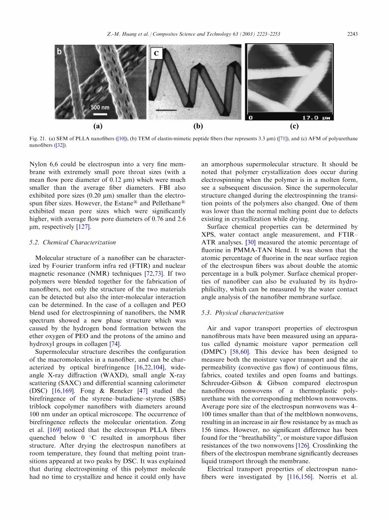
Geometric properties of nanofibers such as fiber dia-meter, diameter distribution, fiber orientation and fibermorphology (e.g. cross-section shape and surfaceroughness) can be characterized using scanning electronmicroscopy (SEM), field emission scanning electronmicroscopy (FESEM), transmission electron micro-scopy (TEM) and atomic force microscopy (AFM)[32,102,114,140]. The use of TEM does not require thesample in a dry state as that of SEM. Hence, nanofiberselectrospun from a polymer solution can be directlyobserved under TEM. An accurate measurement of thenanofiber diameter with AFM requires a rather preciseprocedure. The fibers appear larger than their actualdiameters because of the AFM tip geometry [80]. For aprecise measurement, two fibers crossing to each otheron the surface are generally chosen. The upper hor-izontal tangent of the lower fiber is taken as a reference,and the vertical distance above this reference is con-sidered to be the exact diameter of the upper nanofiber[140]. Fig. 21 shows the nanofiber structures observedthrough SEM, TEM and AFM. AFM can also be usedto characterize the roughness of fibers. The roughnessvalue is the arithmetic average of the deviations ofheight from the central horizontal plane given in termsof millivolts of measured current [32].Another geometric parameter is porosity. The poros-
ity and pore size of nanofiber membranes are importantfor applications of filtration, tissue template, protectiveclothing, etc. [102,127,169]. The pore size measurementcan be conducted by, for example, a capillary flowporometer [102,127,143]. Schreuder-Gibson et al. com-pared the pore sizes of membranes electrospun fromNylon 6,6, FBI (polybenzimidazole), and two poly-urethanes, Estane1 and Pellethane1. They found that
2242 Z.-M. Huang et al. / Composites Science and Technology 63 (2003) 2223–2253
Nylon 6,6 could be electrospun into a very fine mem-brane with extremely small pore throat sizes (with amean flow pore diameter of 0.12 mm) which were muchsmaller than the average fiber diameters. FBI alsoexhibited pore sizes (0.20 mm) smaller than the electro-spun fiber sizes. However, the Estane1 and Pellethane1
exhibited mean pore sizes which were significantlyhigher, with average flow pore diameters of 0.76 and 2.6mm, respectively [127].
5.2. Chemical Characterization
Molecular structure of a nanofiber can be character-ized by Fourier tranform infra red (FTIR) and nuclearmagnetic resonance (NMR) techniques [72,73]. If twopolymers were blended together for the fabrication ofnanofibers, not only the structure of the two materialscan be detected but also the inter-molecular interactioncan be determined. In the case of a collagen and PEOblend used for electrospinning of nanofibers, the NMRspectrum showed a new phase structure which wascaused by the hydrogen bond formation between theether oxygen of PEO and the protons of the amino andhydroxyl groups in collagen [74].Supermolecular structure describes the configuration
of the macromolecules in a nanofiber, and can be char-acterized by optical birefringence [16,22,104], wide-angle X-ray diffraction (WAXD), small angle X-rayscattering (SAXC) and differential scanning calorimeter(DSC) [16,169]. Fong & Reneker [47] studied thebirefringence of the styrene–butadiene–styrene (SBS)triblock copolymer nanofibers with diameters around100 nm under an optical microscope. The occurrence ofbirefringence reflects the molecular orientation. Zonget al. [169] noticed that the electrospun PLLA fibersquenched below 0 �C resulted in amorphous fiberstructure. After drying the electrospun nanofibers atroom temperature, they found that melting point tran-sitions appeared at two peaks by DSC. It was explainedthat during electrospinning of this polymer moleculehad no time to crystallize and hence it could only have
an amorphous supermolecular structure. It should benoted that polymer crystallization does occur duringelectrospinning when the polymer is in a molten form,see a subsequent discussion. Since the supermolecularstructure changed during the electrospinning the transi-tion points of the polymers also changed. One of themwas lower than the normal melting point due to defectsexisting in crystallization while drying.Surface chemical properties can be determined by
XPS, water contact angle measurement, and FTIR–ATR analyses. [30] measured the atomic percentage offluorine in PMMA-TAN blend. It was shown that theatomic percentage of fluorine in the near surface regionof the electrospun fibers was about double the atomicpercentage in a bulk polymer. Surface chemical proper-ties of nanofiber can also be evaluated by its hydro-philicilty, which can be measured by the water contactangle analysis of the nanofiber membrane surface.
5.3. Physical characterization
Air and vapor transport properties of electrospunnanofibrous mats have been measured using an appara-tus called dynamic moisture vapor permeation cell(DMPC) [58,60]. This device has been designed tomeasure both the moisture vapor transport and the airpermeability (convective gas flow) of continuous films,fabrics, coated textiles and open foams and battings.Schreuder-Gibson & Gibson compared electrospunnanofibrous nonwovens of a thermoplastic poly-urethane with the corresponding meltblown nonwovens.Average pore size of the electrospun nonwovens was 4–100 times smaller than that of the meltblown nonwovens,resulting in an increase in air flow resistance by as much as156 times. However, no significant difference has beenfound for the ‘‘breathability’’, or moisture vapor diffusionresistances of the two nonwovens [126]. Crosslinking thefibers of the electrospun membrane significantly decreasesliquid transport through the membrane.Electrical transport properties of electrospun nano-
fibers were investigated by [116,156]. Norris et al.
Fig. 21. (a) SEM of PLLA nanofibers ([10]), (b) TEM of elastin-mimetic peptide fibers (bar represents 3.3 mm) ([71]), and (c) AFM of polyurethane
nanofibers ([32]).
Z.-M. Huang et al. / Composites Science and Technology 63 (2003) 2223–2253 2243
measured the conductivity of the electrospun non-woven ultra-fine fiber mat of polyaniline doped withcamphorsulfonic acid blended with PEO (polyethyleneoxide). As the non-woven mat was highly porous andthe ‘‘fill factor’’ of the fibers was less than that of a castfilm, the measured conductivity seemed to be lower thanthat of the bulk [16]. Wang et al. measured the con-ductivities of PAN (polyacrylonitrile) nanofibers beforeand after carbonized using a digital electrometer withtwo neighboring contacts of 4 mm distance. The elec-trospinning was conducted carefully and briefly so thatthere was only one continuous fiber deposited across thetwo neighboring contacts. The PAN fiber (before car-bonized) exhibited a resistance which was beyond theupper limit of the electrometer, whereas the graphitiza-tion of the PAN nanofiber led to a sharp increase inconductivity to around 490 S/m [156].Kim & Lee [87] characterized the thermal prop-
erties of nanofibers of pure PET [poly (ethylene ter-ephthalate)] and PEN [poly(ethylene naphthalate)]polymers and PET/PEN blends obtained in melt form.They found that the electrospinning of polymers resul-ted in increase of crystallinity and decrease of Tg (glasstransition temperature) and Tc (crystallization peaktemperature) of PET and PEN. The crystalline meltingpeak temperatures (Tm) of PET and PEN were almostthe same before and after electrsopinnning. On theother hand, not only Tg and Tc but also Tm of the elec-trospun PET/PEN nanofibers were lower than those ofthe bulk. The change in thermal properties of electro-spun neat polyesters was primarily resulted fromdecrease of molecular weight after the electrospinningby thermal as well as mechanical degradation. However,the change in those of PET/PEN blends was attributedto exchange reactions of PET and PEN in melt blends[87].
5.4. Mechanical characterization
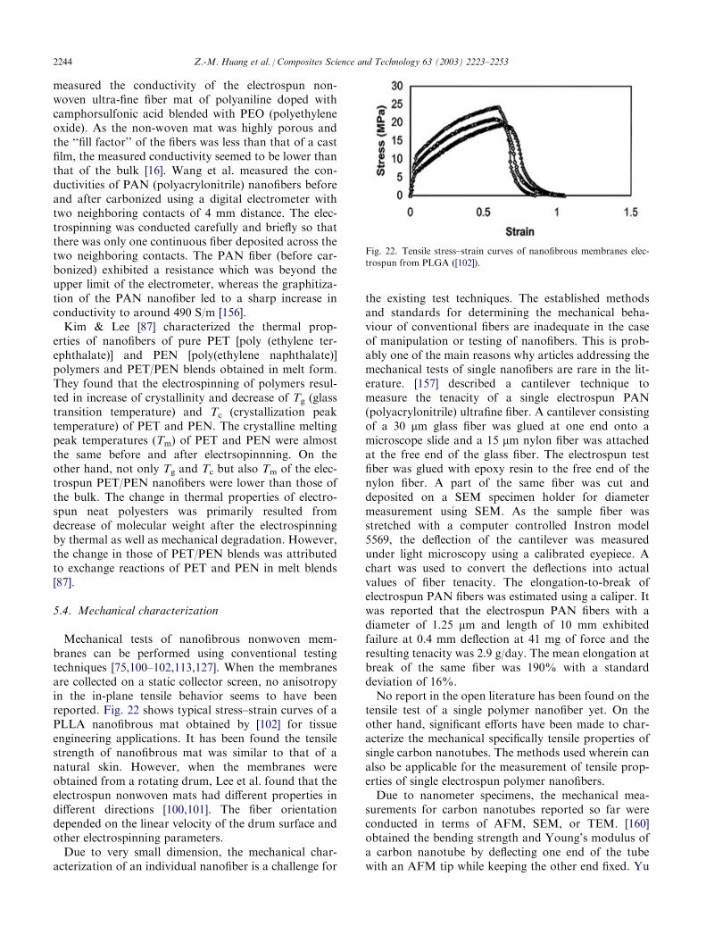
Mechanical tests of nanofibrous nonwoven mem-branes can be performed using conventional testingtechniques [75,100–102,113,127]. When the membranesare collected on a static collector screen, no anisotropyin the in-plane tensile behavior seems to have beenreported. Fig. 22 shows typical stress–strain curves of aPLLA nanofibrous mat obtained by [102] for tissueengineering applications. It has been found the tensilestrength of nanofibrous mat was similar to that of anatural skin. However, when the membranes wereobtained from a rotating drum, Lee et al. found that theelectrospun nonwoven mats had different properties indifferent directions [100,101]. The fiber orientationdepended on the linear velocity of the drum surface andother electrospinning parameters.Due to very small dimension, the mechanical char-
acterization of an individual nanofiber is a challenge for
the existing test techniques. The established methodsand standards for determining the mechanical beha-viour of conventional fibers are inadequate in the caseof manipulation or testing of nanofibers. This is prob-ably one of the main reasons why articles addressing themechanical tests of single nanofibers are rare in the lit-erature. [157] described a cantilever technique tomeasure the tenacity of a single electrospun PAN(polyacrylonitrile) ultrafine fiber. A cantilever consistingof a 30 mm glass fiber was glued at one end onto amicroscope slide and a 15 mm nylon fiber was attachedat the free end of the glass fiber. The electrospun testfiber was glued with epoxy resin to the free end of thenylon fiber. A part of the same fiber was cut anddeposited on a SEM specimen holder for diametermeasurement using SEM. As the sample fiber wasstretched with a computer controlled Instron model5569, the deflection of the cantilever was measuredunder light microscopy using a calibrated eyepiece. Achart was used to convert the deflections into actualvalues of fiber tenacity. The elongation-to-break ofelectrospun PAN fibers was estimated using a caliper. Itwas reported that the electrospun PAN fibers with adiameter of 1.25 mm and length of 10 mm exhibitedfailure at 0.4 mm deflection at 41 mg of force and theresulting tenacity was 2.9 g/day. The mean elongation atbreak of the same fiber was 190% with a standarddeviation of 16%.No report in the open literature has been found on the
tensile test of a single polymer nanofiber yet. On theother hand, significant efforts have been made to char-acterize the mechanical specifically tensile properties ofsingle carbon nanotubes. The methods used wherein canalso be applicable for the measurement of tensile prop-erties of single electrospun polymer nanofibers.Due to nanometer specimens, the mechanical mea-
surements for carbon nanotubes reported so far wereconducted in terms of AFM, SEM, or TEM. [160]obtained the bending strength and Young’s modulus ofa carbon nanotube by deflecting one end of the tubewith an AFM tip while keeping the other end fixed. Yu
Fig. 22. Tensile stress–strain curves of nanofibrous membranes elec-
trospun from PLGA ([102]).
2244 Z.-M. Huang et al. / Composites Science and Technology 63 (2003) 2223–2253
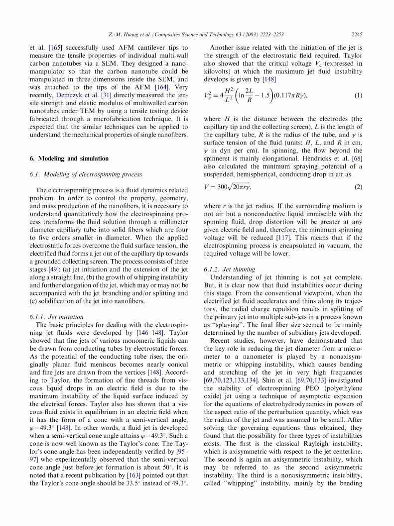
et al. [165] successfully used AFM cantilever tips tomeasure the tensile properties of individual multi-wallcarbon nanotubes via a SEM. They designed a nano-manipulator so that the carbon nanotube could bemanipulated in three dimensions inside the SEM, andwas attached to the tips of the AFM [164]. Veryrecently, Demczyk et al. [31] directly measured the ten-sile strength and elastic modulus of multiwalled carbonnanotubes under TEM by using a tensile testing devicefabricated through a microfabrication technique. It isexpected that the similar techniques can be applied tounderstand the mechanical properties of single nanofibers.
6. Modeling and simulation
6.1. Modeling of electrospinning process
The electrospinning process is a fluid dynamics relatedproblem. In order to control the property, geometry,and mass production of the nanofibers, it is necessary tounderstand quantitatively how the electrospinning pro-cess transforms the fluid solution through a millimeterdiameter capillary tube into solid fibers which are fourto five orders smaller in diameter. When the appliedelectrostatic forces overcome the fluid surface tension, theelectrified fluid forms a jet out of the capillary tip towardsa grounded collecting screen. The process consists of threestages [49]: (a) jet initiation and the extension of the jetalong a straight line, (b) the growth of whipping instabilityand further elongation of the jet, whichmay or may not beaccompanied with the jet branching and/or splitting and(c) solidification of the jet into nanofibers.
6.1.1. Jet initiationThe basic principles for dealing with the electrospin-
ning jet fluids were developed by [146–148]. Taylorshowed that fine jets of various monomeric liquids canbe drawn from conducting tubes by electrostatic forces.As the potential of the conducting tube rises, the ori-ginally planar fluid meniscus becomes nearly conicaland fine jets are drawn from the vertices [148]. Accord-ing to Taylor, the formation of fine threads from vis-cous liquid drops in an electric field is due to themaximum instability of the liquid surface induced bythe electrical forces. Taylor also has shown that a vis-cous fluid exists in equilibrium in an electric field whenit has the form of a cone with a semi-vertical angle,’=49.3� [148]. In other words, a fluid jet is developedwhen a semi-vertical cone angle attains ’=49.3�. Such acone is now well known as the Taylor’s cone. The Tay-lor’s cone angle has been independently verified by [95–97] who experimentally observed that the semi-verticalcone angle just before jet formation is about 50�. It isnoted that a recent publication by [163] pointed out thatthe Taylor’s cone angle should be 33.5� instead of 49.3�.
Another issue related with the initiation of the jet isthe strength of the electrostatic field required. Tayloralso showed that the critical voltage Vc (expressed inkilovolts) at which the maximum jet fluid instabilitydevelops is given by [148]
V2c ¼ 4
H2
L2ln2L
R� 1:5
� �0:117�R�ð Þ; ð1Þ
where H is the distance between the electrodes (thecapillary tip and the collecting screen), L is the length ofthe capillary tube, R is the radius of the tube, and � issurface tension of the fluid (units: H, L, and R in cm,� in dyn per cm). In spinning, the flow beyond thespinneret is mainly elongational. Hendricks et al. [68]also calculated the minimum spraying potential of asuspended, hemispherical, conducting drop in air as
V ¼ 300ffiffiffiffiffiffiffiffiffiffiffiffiffi20�r�
p; ð2Þ
where r is the jet radius. If the surrounding medium isnot air but a nonconductive liquid immiscible with thespinning fluid, drop distortion will be greater at anygiven electric field and, therefore, the minimum spinningvoltage will be reduced [117]. This means that if theelectrospinning process is encapsulated in vacuum, therequired voltage will be lower.
6.1.2. Jet thinningUnderstanding of jet thinning is not yet complete.
But, it is clear now that fluid instabilities occur duringthis stage. From the conventional viewpoint, when theelectrified jet fluid accelerates and thins along its trajec-tory, the radial charge repulsion results in splitting ofthe primary jet into multiple sub-jets in a process knownas ‘‘splaying’’. The final fiber size seemed to be mainlydetermined by the number of subsidiary jets developed.Recent studies, however, have demonstrated that
the key role in reducing the jet diameter from a micro-meter to a nanometer is played by a nonaxisym-metric or whipping instability, which causes bendingand stretching of the jet in very high frequencies[69,70,123,133,134]. Shin et al. [69,70,133] investigatedthe stability of electrospinning PEO (polyethyleneoxide) jet using a technique of asymptotic expansionfor the equations of electrohydrodynamics in powers ofthe aspect ratio of the perturbation quantity, which wasthe radius of the jet and was assumed to be small. Aftersolving the governing equations thus obtained, theyfound that the possibility for three types of instabilitiesexists. The first is the classical Rayleigh instability,which is axisymmetric with respect to the jet centerline.The second is again an axisymmetric instability, whichmay be referred to as the second axisymmetricinstability. The third is a nonaxisymmetric instability,called ‘‘whipping’’ instability, mainly by the bending
Z.-M. Huang et al. / Composites Science and Technology 63 (2003) 2223–2253 2245
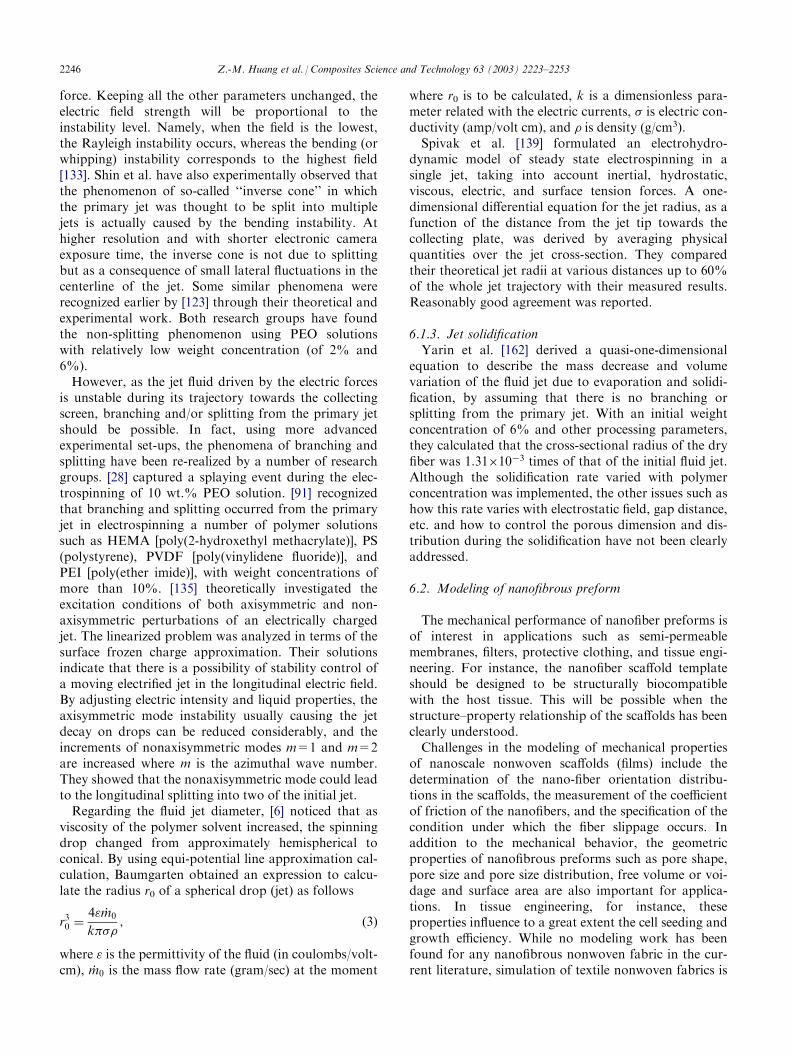
force. Keeping all the other parameters unchanged, theelectric field strength will be proportional to theinstability level. Namely, when the field is the lowest,the Rayleigh instability occurs, whereas the bending (orwhipping) instability corresponds to the highest field[133]. Shin et al. have also experimentally observed thatthe phenomenon of so-called ‘‘inverse cone’’ in whichthe primary jet was thought to be split into multiplejets is actually caused by the bending instability. Athigher resolution and with shorter electronic cameraexposure time, the inverse cone is not due to splittingbut as a consequence of small lateral fluctuations in thecenterline of the jet. Some similar phenomena wererecognized earlier by [123] through their theoretical andexperimental work. Both research groups have foundthe non-splitting phenomenon using PEO solutionswith relatively low weight concentration (of 2% and6%).However, as the jet fluid driven by the electric forces
is unstable during its trajectory towards the collectingscreen, branching and/or splitting from the primary jetshould be possible. In fact, using more advancedexperimental set-ups, the phenomena of branching andsplitting have been re-realized by a number of researchgroups. [28] captured a splaying event during the elec-trospinning of 10 wt.% PEO solution. [91] recognizedthat branching and splitting occurred from the primaryjet in electrospinning a number of polymer solutionssuch as HEMA [poly(2-hydroxethyl methacrylate)], PS(polystyrene), PVDF [poly(vinylidene fluoride)], andPEI [poly(ether imide)], with weight concentrations ofmore than 10%. [135] theoretically investigated theexcitation conditions of both axisymmetric and non-axisymmetric perturbations of an electrically chargedjet. The linearized problem was analyzed in terms of thesurface frozen charge approximation. Their solutionsindicate that there is a possibility of stability control ofa moving electrified jet in the longitudinal electric field.By adjusting electric intensity and liquid properties, theaxisymmetric mode instability usually causing the jetdecay on drops can be reduced considerably, and theincrements of nonaxisymmetric modes m=1 and m=2are increased where m is the azimuthal wave number.They showed that the nonaxisymmetric mode could leadto the longitudinal splitting into two of the initial jet.Regarding the fluid jet diameter, [6] noticed that as
viscosity of the polymer solvent increased, the spinningdrop changed from approximately hemispherical toconical. By using equi-potential line approximation cal-culation, Baumgarten obtained an expression to calcu-late the radius r0 of a spherical drop (jet) as follows
r30 ¼4"m
:0
k�; ð3Þ
where " is the permittivity of the fluid (in coulombs/volt-cm), m
:0 is the mass flow rate (gram/sec) at the moment
where r0 is to be calculated, k is a dimensionless para-meter related with the electric currents, is electric con-ductivity (amp/volt cm), and is density (g/cm3).Spivak et al. [139] formulated an electrohydro-
dynamic model of steady state electrospinning in asingle jet, taking into account inertial, hydrostatic,viscous, electric, and surface tension forces. A one-dimensional differential equation for the jet radius, as afunction of the distance from the jet tip towards thecollecting plate, was derived by averaging physicalquantities over the jet cross-section. They comparedtheir theoretical jet radii at various distances up to 60%of the whole jet trajectory with their measured results.Reasonably good agreement was reported.
6.1.3. Jet solidificationYarin et al. [162] derived a quasi-one-dimensional
equation to describe the mass decrease and volumevariation of the fluid jet due to evaporation and solidi-fication, by assuming that there is no branching orsplitting from the primary jet. With an initial weightconcentration of 6% and other processing parameters,they calculated that the cross-sectional radius of the dryfiber was 1.31�10�3 times of that of the initial fluid jet.Although the solidification rate varied with polymerconcentration was implemented, the other issues such ashow this rate varies with electrostatic field, gap distance,etc. and how to control the porous dimension and dis-tribution during the solidification have not been clearlyaddressed.
6.2. Modeling of nanofibrous preform
The mechanical performance of nanofiber preforms isof interest in applications such as semi-permeablemembranes, filters, protective clothing, and tissue engi-neering. For instance, the nanofiber scaffold templateshould be designed to be structurally biocompatiblewith the host tissue. This will be possible when thestructure–property relationship of the scaffolds has beenclearly understood.Challenges in the modeling of mechanical properties
of nanoscale nonwoven scaffolds (films) include thedetermination of the nano-fiber orientation distribu-tions in the scaffolds, the measurement of the coefficientof friction of the nanofibers, and the specification of thecondition under which the fiber slippage occurs. Inaddition to the mechanical behavior, the geometricproperties of nanofibrous preforms such as pore shape,pore size and pore size distribution, free volume or voi-dage and surface area are also important for applica-tions. In tissue engineering, for instance, theseproperties influence to a great extent the cell seeding andgrowth efficiency. While no modeling work has beenfound for any nanofibrous nonwoven fabric in the cur-rent literature, simulation of textile nonwoven fabrics is
2246 Z.-M. Huang et al. / Composites Science and Technology 63 (2003) 2223–2253
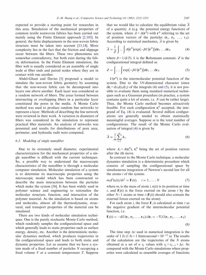
expected to provide a starting point for researches inthis area. Simulation of the mechanical properties ofcommon textile nonwoven fabrics has been carried outmainly using the Finite Element approach [2,103]. Ingeneral, the finite displacements in the non-woven fabricstructure must be taken into account [13,14]. Morecomplexity lies in the fact that the friction and slippageoccur between the fibers. These two phenomena aresomewhat contradictory, but both exist during the fab-ric deformation. In the Finite Element simulation, thefiber web is usually considered as an assembly of singlenode at fiber ends and paired nodes where they are incontact with one another.Abdel-Ghani and Davies [1] proposed a model to
simulate the non-woven fabric geometry by assumingthat the non-woven fabric can be decomposed intolayers one above another. Each layer was considered asa random network of fibers. The areas formed betweenintersecting or overlapping fibers in a particular layerconstituted the pores in the media. A Monte Carlomethod was used to produce random line networks torepresent a layer. Methods of describing the line networkwere reviewed in their work. A variation in diameters offibers was considered in the simulation to representpractical fiber materials. An analysis of networks waspresented and results for distributions of pore area,perimeter, and hydraulic radii were computed.
6.3. Modeling of single nanofiber
Due to its extremely small diameter, experimentalcharacterization for the mechanical properties of a sin-gle nanofiber is difficult with the current techniques.So, a possible way to understand the macroscopiccharacteristics of the nanofiber is through a molecularcomputer simulation. Molecular simulation of a systemis to determine its macroscopic properties using themicroscopic model which has been constructed todescribe the main interactions between the particleswhich make the system [36]. It has been widely used inpolymer science and engineering to rationalize themolecular structure, function, and interaction of thepolymer material. As the simulation is based on atomsand molecules, almost all the thermodynamic, struc-tural, and transport properties of the material can besimulated.There are two kinds of molecular simulation techni-
ques. One is the purely stochastic Monte Carlo method,which randomly samples the configurational space andwhich generally leads to static properties such as surfaceenergy, density, etc. Another is the deterministic molec-ular dynamics method, which produces trajectories inthe configurational space and leads to both static anddynamic properties. Let us assume that we have a sys-tem made of a fixed number of particles N occupying afixed volume V at a constant temperature T. Suppose
that we would like to calculate the equilibrium value Aof a quantity A (e.g. the potential energy function) ofthe system, where A=A(rN) with rN referring to the setof position vectors of the particles (r1, r2, . . ., rN).According to statistical mechanics, A is given by
A ¼1
Z
ð:::
ðA rN� �
exp ��U rN� �� �
dr1 . . . drN ð4Þ
where �=1/(kT). k is the Boltzmann constant. Z is theconfigurational integral defined as
Z ¼
ð. . .
ðexp ��U rN
� �� �dr1 . . . drN ð5Þ
U(rN) is the intermolecular potential function of thesystem. Due to the 3N-dimensional character (sincedri=dxidyidzi) of the integrals (4) and (5), it is not pos-sible to evaluate them using standard numerical techni-ques such as a Gaussian procedure (in practice, a systemcontains quite a lot of atoms, i.e. N can be rather large).Thus, the Monte Carlo method becomes attractivelyfeasible. For each configuration ri
N accepted, the inte-grand of Eq. (4) is evaluated. Several million configur-ations are generally needed to obtain statisticallymeaningful averages. Suppose m is the total number ofconfigurations. The result of the Monte Carlo eval-uation of integral (4) is given by
A ¼1
m
Xmi¼1
Ai; ð6Þ
where Ai=A(riN), ri
N being the set of position vectorsafter the ith move.In contrast to the Monte Carlo technique, a molecular
dynamics simulation is a deterministic procedure whichconsists of sampling the configurational space bysimultaneous integration of Newton’s second law for allthe atoms i of the system:
mid2ri tð Þ=dt
2 ¼ Fi tð Þ; i ¼ 1; . . . ;N ð7Þ
where mi is the mass of atom i, ri(t) is its position at timet, and Fi(t) is the force exerted on the atom i by theother N�1 atoms at time t (Fi(t) should also contain theexternal forces exerted on the atom).For each atom i, the force Fi is calculated at time t as
the negative gradient of the intermolecular potentialfunction, i.e.
Fi tð Þ ¼ �dU r1; r2; . . . ; rNð Þ=dri ¼ �riU r1; r2; . . . ; rNð Þ
ð8Þ
The time step �t used in numerical integration is theorder of 1 fs (1 fs=1 femtosecond=10�15 s). The resultsof the calculation are the trajectories of the N atomsobtained at a set of n tk values with tk=tk�1+�t. Ascompared with the Monte Carlo simulations where prop-erties were calculated as ensemble averages of functions
Z.-M. Huang et al. / Composites Science and Technology 63 (2003) 2223–2253 2247
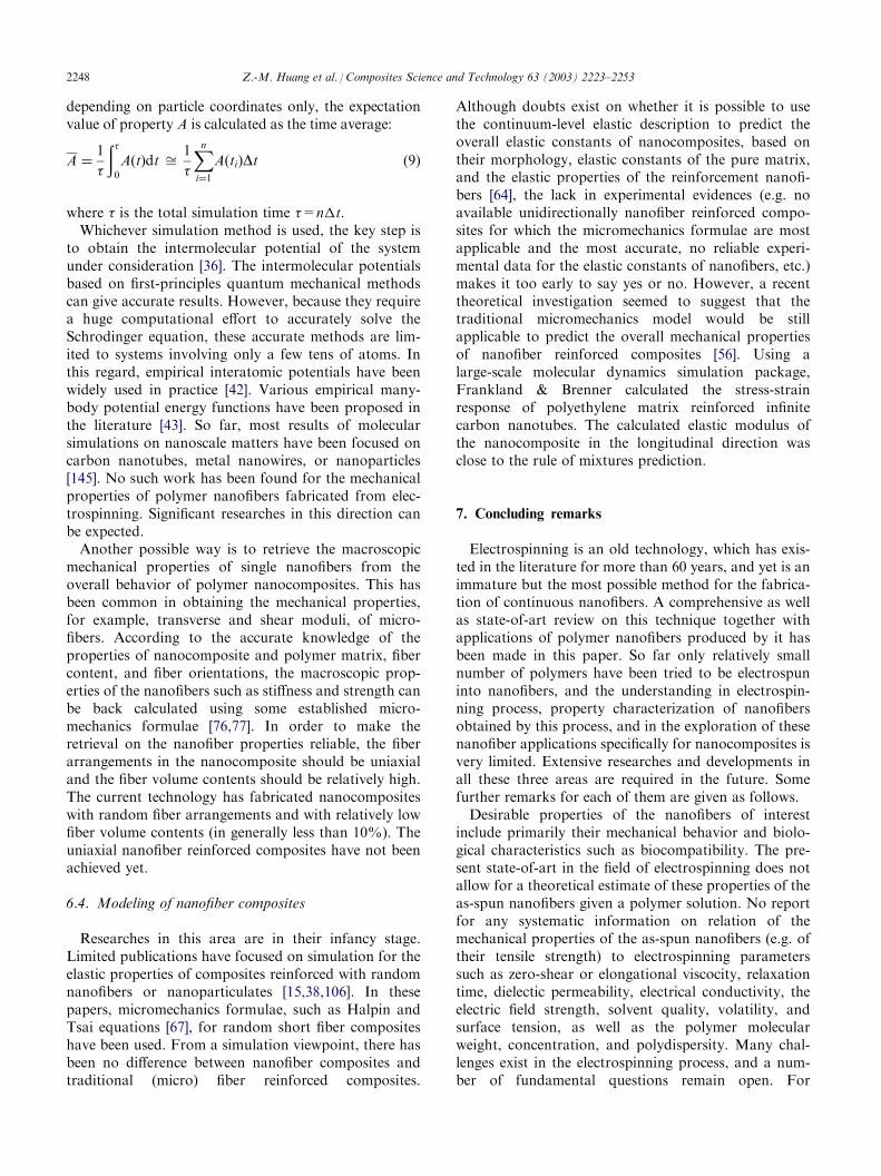
depending on particle coordinates only, the expectationvalue of property A is calculated as the time average:
A ¼1
ð 0
A tð Þdt ffi1
Xni¼1
A tið ÞDt ð9Þ
where is the total simulation time =n�t.Whichever simulation method is used, the key step is
to obtain the intermolecular potential of the systemunder consideration [36]. The intermolecular potentialsbased on first-principles quantum mechanical methodscan give accurate results. However, because they requirea huge computational effort to accurately solve theSchrodinger equation, these accurate methods are lim-ited to systems involving only a few tens of atoms. Inthis regard, empirical interatomic potentials have beenwidely used in practice [42]. Various empirical many-body potential energy functions have been proposed inthe literature [43]. So far, most results of molecularsimulations on nanoscale matters have been focused oncarbon nanotubes, metal nanowires, or nanoparticles[145]. No such work has been found for the mechanicalproperties of polymer nanofibers fabricated from elec-trospinning. Significant researches in this direction canbe expected.Another possible way is to retrieve the macroscopic
mechanical properties of single nanofibers from theoverall behavior of polymer nanocomposites. This hasbeen common in obtaining the mechanical properties,for example, transverse and shear moduli, of micro-fibers. According to the accurate knowledge of theproperties of nanocomposite and polymer matrix, fibercontent, and fiber orientations, the macroscopic prop-erties of the nanofibers such as stiffness and strength canbe back calculated using some established micro-mechanics formulae [76,77]. In order to make theretrieval on the nanofiber properties reliable, the fiberarrangements in the nanocomposite should be uniaxialand the fiber volume contents should be relatively high.The current technology has fabricated nanocompositeswith random fiber arrangements and with relatively lowfiber volume contents (in generally less than 10%). Theuniaxial nanofiber reinforced composites have not beenachieved yet.
6.4. Modeling of nanofiber composites
Researches in this area are in their infancy stage.Limited publications have focused on simulation for theelastic properties of composites reinforced with randomnanofibers or nanoparticulates [15,38,106]. In thesepapers, micromechanics formulae, such as Halpin andTsai equations [67], for random short fiber compositeshave been used. From a simulation viewpoint, there hasbeen no difference between nanofiber composites andtraditional (micro) fiber reinforced composites.
Although doubts exist on whether it is possible to usethe continuum-level elastic description to predict theoverall elastic constants of nanocomposites, based ontheir morphology, elastic constants of the pure matrix,and the elastic properties of the reinforcement nanofi-bers [64], the lack in experimental evidences (e.g. noavailable unidirectionally nanofiber reinforced compo-sites for which the micromechanics formulae are mostapplicable and the most accurate, no reliable experi-mental data for the elastic constants of nanofibers, etc.)makes it too early to say yes or no. However, a recenttheoretical investigation seemed to suggest that thetraditional micromechanics model would be stillapplicable to predict the overall mechanical propertiesof nanofiber reinforced composites [56]. Using alarge-scale molecular dynamics simulation package,Frankland & Brenner calculated the stress-strainresponse of polyethylene matrix reinforced infinitecarbon nanotubes. The calculated elastic modulus ofthe nanocomposite in the longitudinal direction wasclose to the rule of mixtures prediction.
7. Concluding remarks
Electrospinning is an old technology, which has exis-ted in the literature for more than 60 years, and yet is animmature but the most possible method for the fabrica-tion of continuous nanofibers. A comprehensive as wellas state-of-art review on this technique together withapplications of polymer nanofibers produced by it hasbeen made in this paper. So far only relatively smallnumber of polymers have been tried to be electrospuninto nanofibers, and the understanding in electrospin-ning process, property characterization of nanofibersobtained by this process, and in the exploration of thesenanofiber applications specifically for nanocomposites isvery limited. Extensive researches and developments inall these three areas are required in the future. Somefurther remarks for each of them are given as follows.Desirable properties of the nanofibers of interest
include primarily their mechanical behavior and biolo-gical characteristics such as biocompatibility. The pre-sent state-of-art in the field of electrospinning does notallow for a theoretical estimate of these properties of theas-spun nanofibers given a polymer solution. No reportfor any systematic information on relation of themechanical properties of the as-spun nanofibers (e.g. oftheir tensile strength) to electrospinning parameterssuch as zero-shear or elongational viscocity, relaxationtime, dielectic permeability, electrical conductivity, theelectric field strength, solvent quality, volatility, andsurface tension, as well as the polymer molecularweight, concentration, and polydispersity. Many chal-lenges exist in the electrospinning process, and a num-ber of fundamental questions remain open. For
2248 Z.-M. Huang et al. / Composites Science and Technology 63 (2003) 2223–2253
instance, is there any controlling parameter above orbelow which the polymer solution is no longer spin-nable? As seen in Section 2, the polymer solution visc-osity is an important parameter which influences thespinnability. However, different polymers have differentspinnable viscosity ranges. So the solution viscositycannot serve as such controlling parameter. Moreover,evidences exist in that not every polymer solution can beelectrospun into nanofibers. No report has been givenon electrospun polysaccharides nanofibers. We alsohave failed to electrospin chitosan solutions dissolved inits common solvents into ultrafine fibers. The secondchallenge is how to control or even eliminate defectssuch as beads Fig. 4) and pores Fig. 3) in the electro-spun nanofibers. Current efforts have not fully achievedthis purpose yet. The third challenge is to obtain nano-fibers with consistent diameter, whereas the fourthchallenge is in collecting continuous single nanofibers.Still other challenges include fabrication of nanofibersof other kinds of materials such as metals and ceramicsbased on this technique and a significant improvementin nanofiber productivity.So far, no report has been found in the open literature
regarding measurement of the mechanical properties ofsingle polymer nanofibers. Practically nothing is knownon the biological compatibility of as-spun nanofiberswith different types of cells, for example, fibroblasts,bone-marrow-derived mesenchymal stem cells, smoothmuscle cells, etc. The biggest challenge in the mechan-ical (e.g. tensile) characterization is how to isolate asingle nanofiber and then how to grip it into a suffi-ciently small load scale tester.It has been well known that the other mechanical
properties except for the tensile behavior of microfiberssuch as uniaxial compression, transverse, and shearproperties are generally obtained from back calculationof the overall properties of the unidirectional compositereinforced with these microfibers. This kind of proce-dure should also be applicable to the determination ofthe macroscopic mechanical properties of nanofibers.Thus, the challenge is in the fabrication of unidirec-tional nanofiber reinforced composites with relativelyhigh volume fractions.A molecular simulation through Monte Carlo or
Molecular Dynamics method has been successfully usedin polymer science and engineering to rationalize themolecular structure, function, and interaction of thepolymer material and to determine its macroscopicstructure and properties. The biggest challenge inapplying such a simulation to a single polymer nanofi-ber is to determine the structure and arrangement of theparticles consisting of a unit cell of a nanofiber. Anotherchallenge is to establish an interatomic potential func-tion which can describe the interactions of the particlesproperly. Such kind of approach has not been realizedfor a single polymer nanofiber yet.
Because of the limitations as summarized in this paperespecially in processing, practical applications of poly-mer nanofibers are rather limited so far. Most are onlyconsidered as perspective in the future. However, withthe achievement in processing and collecting uniaxiallyaligned continuous nanofibers, more critical applicationsof them as reinforcements for making primary loadnanocomposite elements can be realized. It has beensupposed that nanofibers can have better mechanicalperformance than microfibers. If one can obtain polymernanofibers with comparable properties with micron glassfibers, for instance, one can use them for the develop-ment of archwires and brackets and can expect them tohave better mechanical and esthetic characteristics [78].Furthermore, by using electrospun biodegradable nano-fibers, one may be able to develop non-removable implantssuch as bone plates [57] with much improved mechanicalproperties than those ever seen in the literature.
Acknowledgements
The authors would like to acknowledge ProfessorA.L. Yarin, Technion-Israel Institute of Technology,Dr. Krishnan Jayaraman, University of Auckland, andDr. Xiumei Mo, National University of Singapore, fortheir kind help and assistance.
References
[1] Abdel-Ghani MS, Davies GA. Simulation of non-woven fiber
mats and the application to coalescers. Chemical Engineering
Science 1985;40(1):117–29.
[2] Adanur S, Liao T. Computer imulation of mechanical proper-
ties of nonwoven geotextiles in soil-fabric interaction. Textile
Res J 1998;68:155–62.
[3] Angadjivand SA, Schwartz MG, Eitzman PD, Jones ME. US
patent, 6375886. 2002.
[4] Athreya SA, Martin DC. Impedance spectroscopy of protein
polymer modified silicon micromachined probes. Sensors and
Actuators A—Physical 1999;72(3):203–16.
[5] Baughman RH, Zakhidov AA, de Heer WA. Carbon nano-
tubes—the route toward applications. Science 2002;297:787–92.
[6] Baumgarten PK. Electrostatic spinning of acrylic microfibers. J
of Colloid and Interface Science 1971;36:71–9.
[7] Bergshoef MM, Vancso GJ. Transparent nanocomposites with
ultrathin, electrospun Nylon-4,6 fiber reinforcement. Adv Mater
1999;11(16):1362–5.
[8] Berry JP. US patent 4965110, 1990.
[9] Bognitzki M, Hou H, Ishaque M, Frese T, Hellwig M, Schwarte
C, et al. Polymer, metal, and hybrid nano- and mesotubes by
coating degradable polymer template fibers (TUFT process).
Adv Mater 2000;12(9):637–40.
[10] Bognitzki M, Czado W, Frese T, Schaper A, Hellwig M, Stein-
hart M, et al. Nanostructured fibers via electrospinning. Adv
Mater 2001;13:70–2.
[11] Boland ED, Wnek GE, Simpson DG, Palowski KJ, Bowlin GL.
Tailoring tissue engineering scaffolds using electrostatic proces-
sing techniques: a study of poly(glycolic acid) electrospinning. J
Macromol Sci Pur Appl Chem 2001;A38(12):1231–43.
Z.-M. Huang et al. / Composites Science and Technology 63 (2003) 2223–2253 2249
[12] Bornat A. Production of electrostatically spun products. US
Patent 4689186. 1987.
[13] Britton PN, Sampson AJ, Elliott Jr CF, Graben HW, Gettys
WE. Computer simulation of the mechanical properties of non-
woven fabrics. Part I: the method. Textile Res J 1983;53(6):363–
8.
[14] Britton PN, Sampson AJ, Gettys WE. Computer simulation of
the mechanical properties of nonwoven fabrics. Part II: bond
breaking. Textile Res J 1984;54(1):1–5.
[15] Brune DA, Bicerano J. Micromechanics of nanocomposites
comparison of tensile and compressive elastic moduli, and pre-
diction of effects of incomplete exfoliation and imperfect align-
ment on modulus. Polymer 2002;43(2):369–87.
[16] Buchko CJ, Chen LC, Shen Y, Martin DC. Processing and
microstructural characterization of porous biocompatible pro-
tein polymer thin films. Polymer 1999;40:7397–407.
[17] Buchko CJ, Slattery MJ, Kozloff KM, Martin DC. Mechanical
properties of biocompatible protein polymer thin films. J Mat
Res 2000;15(1):231–42.
[18] Buchko CJ, Kozloff KM, Martin DC. Surface characterization
of porous, biocompatible protein polymer thin films. Biomater-
ials 2001;22(11):1289–300.
[19] Chamberlain G, Joyce M. Design News 1990:20.
[20] Chand S. Review: carbon fibers for composites. J Mater Sci
2000;35:1303–13.
[21] Caruso RA, Schattka JH, Greiner A. Titanium dioxide tubes
from sol-gel coating of electrospun polymer fibers. Advanced
Materials 2001;13(20):1577–9.
[22] Chen ZH, Foster MD, Zhou WS, Fong H, Reneker DH,
Resendes R, et al. Structure of poly(ferrocenyldimethylsilane) in
electrospun nanofibers. Macromolecules 2001;34(18):6156–8.
[23] Chun I, Reneker DH, Fang XY, Fong H, Deitzel J, Tan NB, et
al. Carbon nanofibers from polyacrylonitrile and mesophase
pitch. International SAMPE Symposium and Exhibition (Pro-
ceedings) 1998;43(1):718–29.
[24] Chun I, Reneker DH, Fong H, Fang X, Deitzel J, Tan NB, et al.
Carbon nanofibers from polyacrylonitrile and mesophase pitch.
Journal of Advanced Materials 1999;31(1):36–41.
[25] Coffee RA. PCT/GB97/01968, 1998.
[26] Couillard RAA, Chen Z, Schwartz P. Spinning fine fibers from
solutions and the melt using electrostatic fields, Book of
Abstracts. In: New frontiers in fiber science, Spring Meeting.
2001. Available from: http://www.tx.ncsu.edu/jtatm/volume1-
specialissue/presentations/pres_part1.doc.
[27] Dai H-Q, Gong J, Kim H, Lee D. A novel method for preparing
ultra-fine alumina-borate oxide fibers via an electrospinning
technique. Nanotechnology 2002;13(5):674–7.
[28] Deitzel JM, Kleinmeyer J, Harris D, Tan NCB. The effect of
processing variables on the morphology of electrospun nanofi-
bers and textiles. Polymer 2001;42:261–72.
[29] Deitzel JM, Kleinmeyer J, Hirvonen JK, Beck TNC. Controlled
deposition of electrospun poly(ethylene oxide) fibers. Polymer
2001;42:8163–70.
[30] Deitzel JM, Kosik W, McKnight SH, Ten NCB, Desimone JM,
Crette S. Electrospinning of polymer nanofibers with specific
surface chemistry. Polymer 2002;43(3):1025–9.
[31] Demczyk BG, Wang YM, Cumings J, Hetman M, Han W, Zettl
A, et al. Direct mechanical measurement of the tensile strength
and elastic modulus of multiwalled carbon nanotubes. Materials
Science and Engineering A 2002;334:173–8.
[32] Demir MM, Yilgor I, Yilgor E, Erman B. Electrospinning of
polyurethane fibers. Polymer 2002;43:3303–9.
[33] Diaz-De Leon MJ. Electrospinning nanofibers of polyaniline
and polyaniline/(polystyrene and polyethylene oxide) blends. In:
Proceeding of The National Conference on Undergraduate
Research (NCUR), University of Kentucky, 15–17 March.
Lexington, Kentucky (USA); 2001.
[34] Ding B, Kim H-Y, Lee S-C, Shao C-L, Lee D-R, Park S-J, et al.
Preparation and Characterization of a nanoscale poly(vinyl
alcohol) fiber aggregate produced by an electrospining method.
Journal of Polymer Science: Part B: Polymer Physics 2002;40:
1261–8.
[35] Doshi J, Reneker DH. Electrospinning process and applica-
tions of electrospun fibers. J Electrostatics 1995;35(2-3):151–
60.
[36] Doucet JP, Weber J. Computer-aided molecular design: theory
and applications. London: Academic Press; 1996.
[37] Drozin VG. J of Colloid Science 1955;10:158.
[38] Dzenis YA. Hierarchical nano-/micromaterials based on elec-
trospun polymer fibers: predictive models for thermomechanical
behavior. J Computer-Aided Mater Des 1996;3:403–8.
[39] Dzenis YA, Reneker DH. Delamination resistant composites
prepared by small diameter fiber reinforcement at ply interfaces,
US Patent No. 626533, 2001.
[40] Dzenis YA, Wen YK. Continuous carbon nanofibers for nano-
fiber composites. Materials Research Society Symposium—Pro-
ceedings 2002;702:173–8.
[41] Emig D, Klimmek A, Raabe E. US Patent 6395046. 2002.
[42] Engkvist O, Astrand PO, Karlstrom G. Accurate intermolecular
potentials obtained from molecular wave functions: bridging the
gap between quantum chemistry and molecular simulations.
Chem Rev 2000;100:4087–108.
[43] Erkoc S. Empirical many-body potential energy functions used
in computer simulations of condensed matter properties. Physics
Reports 1997;278:79–105.
[44] Fang X, Reneker DH. DNA fibers by electrospinning. J Macro-
molecular Sci-Phys 1997;B36:169–73.
[45] Feng L, Li S, Li H, Zhai J, Song Y, Jiang L, et al. Super-
Hydrophobic Surface of Aligned Polyacrylonitrile Nanofibers.
Angew Chem Int Ed 2002;41(7):1221–3.
[46] Fertala A, Han WB, Ko FK. Mapping critical sites in collagen
II for rational design of gene-engineered proteins for cell-sup-
porting materials. J Biomed Mater Res 2001;57:48–58.
[47] Fong H, Chun I, Reneker DH. Beaded nanofibers formed dur-
ing electrospinning. Polymer 1999;40:4585–92.
[48] Fong H, Reneker DH. Elastomeric nanofibers of styrene-buta-
diene-styrene triblock copolymer. J Polym Sci: Part B Polym
Phys 1999;37(24):3488–93.
[49] Fong H, Reneker DH. Electrospinning and formation of nano-
fibers. In: Salem DR, editor. Structure formation in polymeric
fibers. Munich: Hanser; 2001. p. 225–46.
[50] Fong H, Liu W-D, Wang C-S, Vaia RA. Generation of electro-
spun fibers of nylon 6 and nylon 6-montmorillonite nano-
composite. Polymer 2002;43(3):775–80.
[51] Formhals A. US patent 1,975,504, 1934.
[52] Formhals A. US patent 2,160,962, 1939.
[53] Formhals A. US patent, 2,187,306, 1940.
[54] Formhals A. US patent, 2,323,025, 1943.
[55] Formhals A. US patent, 2,349,950, 1944.
[56] Frankland SJV, Brenner DW. Molecular dynamics simula-
tions of polymer-nanotube composites. Materials Research
Society Symposium Proceedings, Vol. 593, 2000, pp. 199–
204.
[57] Fujihara K, Huang ZM, Ramakrishna S, Satknanantham K,
Hamada H. Performance study of braided carbon/PEEK com-
posite compression bone plates. Biomaterials [in press].
[58] Gibson PW, Kendrick C, Rivin D, Charmchi M, Sicuranza L.
An automated water vapor diffusion test method for fabrics,
laminates, and films. J Coated Fabrics 1995;24:322.
[59] Gibson PW, Schreuder-Gibson HL, Pentheny C. Electrospin-
ning technology: direct application of tailorable ultrathin mem-
branes. J of Coated Fabrics 1998;28:63.
[60] Gibson PW, Schreuder-Gibson HL, Riven D. Electrospun fiber
mats: transport properties. AIChE J 1999;45(1):190–5.
2250 Z.-M. Huang et al. / Composites Science and Technology 63 (2003) 2223–2253
[61] Gibson PW, Schreuder-Gibson HL, Rivin D. Transport prop-
erties of porous membranes based on electrospun nanofibers.
Colloids and Surfaces A: Physicochemical and Engineering
Aspects 2001;187:469–81.
[62] Graham K, Ouyang M, Raether T, Grafe T, McDonald B,
Knauf P. Fifteenth Annual Technical Conference & Expo of the
American Filtration & Separations Society, Galveston, TX; 9–
12 April 2002.
[63] Graham S. ‘Smart’ silicon dust could help screen for chemical
weapons. Scientific American 2002:3.
[64] Grigoras S, Gusev AA, Santos S, Suter UW. Evaluation of the
elastic constants of nanoparticles from atomistic simulations.
Polymer 2002;43:489–94.
[65] Groitzsch D, Fahrbach E. US patent 4,618,524, 1986.
[66] Hajra MG, Mehta K, Chase GG. Effects of humidity, tempera-
ture, a nanofibers on drop coalescence in glass fiber media.
Separation and Purification Technology 2003;30:79–88.
[67] Halpin JC. Primer on composite materials analysis. 2nd ed.
Lancaster, Basel: Technomic Publishing Co.; 1992.
[68] Hendricks Jr CD, Carson RS, Hogan JJ, Schneider JM. Photo-
micrography of electrically sprayed heavy particles. AIAA J
1964;2(4):733–7.
[69] Hohman MM, Shin M, Rutledge G, Brenner MP. Electrospin-
ning and electrically forced jets. I. Stability theory. Physics of
Fluids 2001;13:2201–20.
[70] Hohman MM, Shin M, Rutledge G, Brenner MP. Electrospin-
ning and electrically forced jets. II. Applications. Physics of
Fluids 2001;13:2221–36.
[71] Hou HQ, Jun Z, Reuning A, Schaper A, Wendorff JH, Greiner A.
Poly(p-xylylene) nanotubes by coating and removal of ultrathin
polymer template fibers. Macromolecules 2002;35(7):2429–31.
[72] How TV. US patent, 4552707, 1985.
[73] Huang L, McMillan RA, Apkarian RP, Pourdeyhimi B, Con-
ticello VP, Chaikof EL. Generation of synthetic elastin-mimetic
small diameter fibers and fiber networks. Macromolecules 2000;
33(8):2989–97.
[74] Huang L, Apkarian RP, Chaikof EL. High-Resolution analysis
of engineered type I collagen nanofibers by electron microscopy.
Scanning 2001a;23:372–5.
[75] Huang L, Nagapudi K, Apkarian R, Chaikof EL. Engineered
collagen-PEO nanofibers and fabrics. J Biomater Sci Polym Edn
2001b;12(9):979–94.
[76] Huang ZM. Micromechanical strength formulae of unidirec-
tional composites. Materials Letters 1999;40(4):164–9.
[77] Huang ZM. Simulation of the mechanical properties of fibrous
composites by the bridging micromechanics model. Composites
Part A 2001;32:143–72.
[78] Huang ZM, Gopal R, Fujihara K, Ramakrishna S, Loh PL,
Foong WC. et al. Fabrication of a new composite orthodontic
archwire and validation by a bridging micromechanics model.
Biomaterials, Vol. 24, 2003, pp. 2941–2953.
[79] Ignatious F, Baldoni JM. PCT/US01/02399, 2001.
[80] Jaeger R, SchOnherr H, Vancso GJ. Chain packing in electro-
spun poly(ethylene oxide) visualized by atomic force micro-
scopy. Macromolecules 1996;29:7634–6.
[81] Jia HF, Zhu GY, Vugrinovich B, Kataphinan W, Reneker DH,
Wang P. Enzyme-carrying polymeric nanofibers prepared via
electrospinning for use as unique biocatlysts. Biotechnology
Progress 2002;18(5):1027–32.
[82] Jin HJ, Fridrikh S, Rutledge GC, Kaplan D. Electrospinning
Bombyx mori silk with poly(ethylene oxide). Abstracts of
Papers American Chemical Society 2002;224(1–2):408.
[83] Kenawy E-R, Abdel-Fattah YR. Antimicrobial properties of
modified and electrospn poly (vunl phenol). Macromolecular
Bioscience 2002;2:261–6.
[84] Kenawy ER, Bowlin GL, Mansfield K, Layman J, Simpson
DG, Sanders EH, et al. Release of tetracycline hydrochloride
from electrospun poly(ethylene-co-vinylacetate), poly(lactic
acid), and a blend. Journal of Controlled Release 2002;81:57–64.
[85] Kenawy E-R, Layman JM, Watkins JR, Bowlin GL, Matthews
JA, Simpson DG, et al. Electrospinning of poly (ethylene-co-
vinyl alcohol) fibers. Biomaterials 2003;24:907–13.
[86] Kim J-S. Improved mechanical properties of composites using
ultrafine electrospun fibers. PhD dissertation, The Graduate
Faculty of the University of Akron, 1997.
[87] Kim J-S, Lee D-S. Thermal properties of electrospun polyesters.
Polymer J 2000;32(7):616–8.
[88] Kim J-S, Reneker D. H, Mechanical properties of composites
using ultrafine electrospun fibers. Polymer Composites 1999;
20(1):124–31.
[89] Ko FK, Khan S, Ali A, Gogotsi Y, Naguib N, Yang G-L, et al.
Structure and properties of carbon nanotube reinforced nano-
composites, Collection of Technical Papers—AIAA/ASME/
ASCE/AHS/ASC Structures. Structural Dynamics and Materi-
als Conference 2002;3:1779–87.
[90] Koombhongse S, Liu WX, Reneker DH. Flat polymer ribbons
and other shapes by electrospinning. J Polymer Sci: Part B:
Polymer Physics 2001;39:2598–606.
[91] Koombhongse S, Reneker DH. Branched and split fiber from
electrospinning process, Book of Abstracts. In: New Frontiers in
Fiber Science, Spring Meeting 2001. Available from: http://
www.tx.ncsu.edu/jtatm/volume1specialissue/posters/posters_
part1.pdf.
[92] Krishnappa RVN, Sung CM, Schreuder-Gibson H. Electro-
spinning of Polycarbonates and their surface characterization
using the SEM and TEM. Mat Res Soc Symp Proc 2002;702:
U6.7.1–0U6.7.6.
[93] Kwoun SJ, Lec RM, Han B, Ko FK. A novel polymer nanofiber
interface for chemical sensor applications. In: Proceedings of the
2000 IEEE/EIA International Frequency Control Symposium
and Exhibilition. 2000, p. 52–7.
[94] Kwoun SJ, Lec RM, Han B, Ko FK. Polymer nanofiber thin
films for biosensor applications. In: Proceedings of the IEEE
27th Annual Northeast Bioengineering Conference, 2001. p. 9–
10.
[95] Larrondo, Manley R., St J. Electrostatic fiber spinning from
polymer melts, I. and Experimental observations on fiber for-
mation and properties. J Polymer Science: Polymer Physics
Edition 1981;19:909–20.
[96] Larrondo, Manley R., St J. Electrostatic fiber spinning from
polymer melts. II. Examination of the flow field in an elec-
trically driven jet. J Polymer Sci: Polymer Physics Ed 1981;
19:921–32.
[97] Larrondo, Manley R., St J. Electrostatic fiber spinning from
polymer melts. III. Electrostatic deformation of a pendant drop
of polymer melt. J Polymer Sci: Polymer Physics Ed 1981;19:
933–40.
[98] Lau K-T, Hui D. The revolutionary creation of new advanced
materials-carbon nanotube composites. Composites Part B
2002;33(4):263–77.
[99] Laurencin CT, Ambrosio AMA, Borden MD, Cooper Jr JA.
Tissue engineering: orthopedic applications. Annu Rev Biomed
Eng 1999;1:19–46.
[100] Lee KH, Kim HY, La YM, Lee DR, Sung NH. Influence of a
mixing solvent with tetrahydrofuran and N,N-dimethylforma-
mide on electrospun poly(vinylchloride) nonwoven mats. J
Polymer Sci Part B: Polymer Physics 2002;40:2259–68.
[101] Lee SH, Ku BC, Wang X, Samuelson LA, Kumar J. Design,
synthesis and electrospinning of a novel fluorescent polymer for
optical sensor applications. Mat Res Soc Symp Pro 2002;708:
403–8.
[102] Li WJ, Laurencin CT, Caterson EJ, Tuan RS, Ko FK. Electro-
spun nanofibrous structure: A novel scaffold for tissue engi-
neering. J Biomed Mater Res 2002;60(4):613–21.
Z.-M. Huang et al. / Composites Science and Technology 63 (2003) 2223–2253 2251
[103] Liao T, Adanur S. Computerized failure analysis of nonwoven
fabrics based on fiber failure criterion. Textile Res J 1999;69:
489–96.
[104] Liu GJ, Ding JF, Qiao LJ, Guo A, Dymov BP, Gleeson JT, et
al. Polystyrene-block-poly (2-cinnamoylethyl methacrylate)
nanofibers-Preparation, characterization, and liquid crystalline
properties. Chem-A European J 1999;5:2740–9.
[105] Liu HQ, Hsieh YL. Ultrafine fibrous cellulose membranes from
electrospinning of cellulose acetate. J of Polyer Sci Part B:
Polymer Physics 2002;40:2119–29.
[106] Ma PX, Zhang R. Synthetic nano-scale fibrous extracellular
matrix. J Biomed Mat Res 1999;46:60–72.
[107] MacDiarmid AG, Ones Jr WE, Norris ID, Gao J, Johnson AT,
Pinto NJ, et al. Electrostatically-generated nanofibers of elec-
tronic polymers. Synthetic Metals 2001;119:27–30.
[108] Martin CR. Membrane-based synthesis of nanomaterials. Chem
Mater 1996;8:1739–46.
[109] Martin GE, Cockshott ID, Fildes FJT. US patent 4044404,
1977.
[110] Martin GE, Cockshott ID, Fildes FJT. US patent 4878908,
1989.
[111] Martindale D. Scientific American 2000:34–6.
[112] Maruyama B, Alam K. Carbon nanotubes and nanofibers in
composite materials. SAMPE J 2002;38(3):59–70.
[113] Matthews JA, Wnek GE, Simpson DG, Bowlin GL. Electro-
spinning of Collagen Nanofibers. Biomacromolecules 2002;3(2):
232–8.
[114] Megelski S, Stephens JS, Rabolt JF, Bruce CD. Micro-and
nanostructured surface morphology on electrospun polymer
fibers. Macromolecules 2002;35(22):8456–66.
[115] Morozov VN, Morozova TY, Kallenbach NR. Atomic force
microscopy of structures produced by electrospraying polymer
solutions. International Journal of Mass Spectrometry 1998;178:
143–59.
[116] Norris ID, Shaker MM, Ko FK, Macdiarmid AG. Electrostatic
fabrication of ultrafine conducting fibers: polyaniline/poly-
ethylene oxide blends. Synthetic Metals 2000;114(2):109–14.
[117] O’Konski CT, Thacher Jr HC. J Phys Chem 1953;57:955.
[118] Ondarcuhu T, Joachim C. Drawing a single nanofibre over
hundreds of microns. Europhys Lett 1998;42(2):215–20.
[119] Park C, Ounaies Z, Watson KA, Pawlowski K, Lowther SE,
Connell JW, et al. Polymer-single wall carbon nanotube com-
posites for potential spacecraft applications. Making Functional
Materials with Nanotubes Symposium (Materials Research
Society Symposium Proceedings 2002;706:91–6.
[120] Rangkupan R., Reneker DH. Electrospinning from a polymer
melt in a vacuum. In: arch Meeting 2000, L36.059. Available
from: http://www.eps.org/aps/meet/MAR00/baps/abs/
S4750059.html.
[121] Rangkupan R, Reneker DH. Development of electrospinning
from molten polymers in vacuum, Book of Abstracts. In: New
frontiers in fiber science, Spring Meeting 2001. Availble from:
http://www.tx.ncsu.edu/jtatm/volume1specialissue/posters/pos-
ters_ part1.pdf.
[122] Reneker DH, Chun I. Nanometre diameter fibres of polymer,
produced by electrospinning. Nanotechnology 1996;7:216–23.
[123] Reneker DH, Yarin AL, Fong H, Koombhongse S. Bending
instability of electrically charged liquid jets of polymer solutions
in electrospinning. J Appl Phys 2000;87:4531–47.
[124] Reneker DH, Yarin A, Evans EA, Kataphinan W, Rangkupan
R, Liu W. et al. Electrospinning and nanofibers, Book of
Abstracts. In: New Frontiers in Fiber Science, Spring Meeting
2001. Available from: http://www.tx.ncsu.edu/jtatm/volume1spe
cialissue/presentations/pres_part1.doc.
[125] Rutledge GC, Li Y, Fridrikh S, Warner SB, Kalayci VE, Patra,
P. Electrostatic spinning and properties of ultrafine fibers. In:
National Textile Center, 2000. Annual Report (M98-D01),
National Textile Center; 2000. Available from: http://heavenly.
mit.edu/rutledge/PDFs/NTCannual99.pdf.
[126] Schreuder-Gibson HL, Gibson P. Transport properties of elec-
trospun nonwoven membranes. Int Nonwoven J 2002;11(2):21–
6.
[127] Schreuder-Gibson HL, Gibson P, Senecal K, Sennett M, Walker
J, Yeomans W, et al. Protective textile materials based on elec-
trospun nanofibers. Journal of Advanced Materials 2002;34(3):
44–55.
[128] Scopelianos AG. US patent, 5522879, 1996.
[129] Senador Jr AE, Shawa MT, Mathera PT. Electrospinning of
Polymeric Nanofibers: Analysis of Jet Formation. Mat Res Soc
Symp Proc 2001;661:KK5.9.1–0KK5.9.
[130] Senecal KJ, Samuelson L, Sennett M, Schreuder GH. US patent
application publication 0045547, 2001.
[131] Senecal KJ, Ziegler DP, He J, Mosurkal R, Schreuder-Gibson
H, Samuelson LA. Photoelectric response from nanofibrous
membranes. Materials Research Society Symposium Proceed-
ings 2002;708:285–9.
[132] Shao CL, Kim H-Y, Gong J, Ding B, Lee D-R, Park S-J. Fiber
mats of poly(vinyl alcohol)/silica composite via electrospinning.
Materials Letters 2002;56(1-2):24–9.
[133] Shin YM, Hohman MM, Brenner MP, Rutledge GC. Electro-
spinning: A whipping fluid jet generates submicron polymer
fibers. Appl Phys Lett 2001;78:1149–51.
[134] Shin YM, Hohman MM, Brenner MP, Rutledge GC. Experi-
mental characterization of electrospinning: the electrically
forced jet and instabilities. Polymer 2001;42:9955–67.
[135] Shkadov VYa, Shutov AA. Disintegration of a charged vis-
cous jet in a high electric field. Fluid Dynamics Research
2001;28:23–9.
[136] Simons HL. US patent 3,280,229, 1966.
[137] Smith D., Reneker DH. PCT/US00/27737. 2001.
[138] Smith D, Reneker DH, Schreuder GH, Mello C, Sennett M,
Gibson P. PCT/US00/27776, 2001.
[139] Spivak AF, Dzenis YA, Reneker DH. A Model of steady state
jet in the electrospinning process. Mechanics of Research
Communications 2000;27(1):37–42.
[140] Srinivasan G, Reneker DH. Structure and morphology of small-
diameter electrospun aramid fibers. Polym Int 1995;36(2):195–
201.
[141] Stephens JS, Frisk S, Meglski S, Rabolt JF, Chase DB. Real
time Raman studies of electrospun fibers. Applied Spectroscopy
2001;55(10):1287–90.
[142] Stenoien MD, Drasler WJ, Scott RJ, Jenson ML. US patent.
5866217, 1999.
[143] Stillwell CR. Characterization of Pore Structure in Filter Car-
tridges. Advances in Filtration and Separation Technology
1996;10.
[144] Suthat A, Chase G. Chemical Engineer 2001:26–8.
[145] Tabar HR. Modeling the nano-scale phenomena in condensed
matter physics via computer based numerical simulations. Phy-
sics Reports 2000;325:239–310.
[146] Taylor GI. Disintegration of water drops in an electric field.
Proc R Soc London, Ser A 1964;280:383.
[147] Taylor GI. The circulation produced in a drop by an electric
field. Proc R Soc London, Ser A 1966;291:159.
[148] Taylor GI. Electrically driven jets. Proc R Soc London, Ser A
1969;313:453–75.
[149] Theron A, Zussman E, Yarin AL. Electrostatic field-assisted
alignment of electrospun nanofibres. Nanotechnology 2001;12:
384–90.
[150] Thostenson ET, Ren ZF, Chou TW. Advances in the science
and technology of carbon nanotubes and their composites: a
review. Comp Sci & Tech 2001;61(13):1899–912.
[151] Torres B. Ultrafine fibers of polystyrene dissolved in tetra-
hydrofuran prepared using the electrospinning method. In: Pro-
2252 Z.-M. Huang et al. / Composites Science and Technology 63 (2003) 2223–2253
ceeding of The National Conference On Undergraduate
Research, 2001. 15–17: p.1–5
[152] Tsaia PP, Schreuder-Gibson H, Gibson P. Different electrostatic
methods for making electret filters. Journal of Electrostatics
2002;54:333–41.
[153] Vonnegut B, Neubauer RL. J of Colloid Science 1952;7:616.
[154] Wang XY, Lee SH, Drew C, Senecal KJ, Kumar J, Samuelson
LA. Highly sensitive optical sensors using electrospun polymeric
nanofibrous membranes. Mat Res Soc Symp Pro 2002;708:397–
402.
[155] Wang XY, Drew C, Lee S-H, Senecal KJ, Kumar J, Samuelson
LA. Electrospun nanofibrous membranes for highly sensitive
optical sensors. Namo Letters 2002;2(11):1273–5.
[156] Wang Y, Serrano S, Santiago-Aviles JJ. Conductivity measure-
ment of electrospun PAN-based carbon nanofiber. Journal of
Materials Science Letters 2002;21(13):1055–7.
[157] Warner SB, Buer A, Grimler M, Ugbolue SC, Rutledge GC,
Shin MY. A fundamental investigation of the formation and
properties of electrospun fibers. In: 1999 Annual Report (M98-
D01), National Textile Center, 1999. Available from: http://
heavenly. mit.edu/rutledge/PDFs/NTCannual99.pdf.
[158] Warner SB, Buer A, Grimler M, Ugbolue SC, Rutledge GC,
Shin MY. A fundamental investigation of the formation and
properties of electrospun fibers. In: 2001 Annual Report (M98-
D01), National Textile Center, 2001. Available from: http://
heavenly. mit.edu/rutledge/PDFs/NTCannual99.pdf.
[159] Waters CM, Noakes TJ, Pavery I, Hitomi C. US patent
5088807, 1992.
[160] Wong EW, Sheehan PE, Lieber CM. Nanobeam mechanics:
elasticity, strength, and toughness of nanorods and nanotubes.
Science 1997;277:1971–5.
[161] Whitesides GM, Grzybowski B. Self-assembly at all scales.
Science 2002;295:2418–21.
[162] Yarin AL, Koombhongse S, Reneker DH. Bending instability in
electrospinning of nanofibers. J Appl Phys 2001;89(5):3018–26.
[163] Yarin AL, Koombhongse S, Reneker DH. Taylor cone and jet-
ting from liquid droplets in electrospinning of nanofibers. J
Appl Phys 2001;89(9):4836–46.
[164] Yu MF, Dyer MJ, Skidmore GD, Rohrs HW, Lu XK, Ausman
KD, et al. Three-dimensional manipulation of carbon nano-
tubes under a scanning electron microscope. Nanotechnology
1999;10:244–52.
[165] Yu MF, Lourie O, Dyer MJ, Moloni K, Kelly TF, Ruoff RS.
Strength and breaking mechanism of multiwalled carbon nano-
tubes under tensile load. Science 2000;287(5453):637–40.
[166] Yun KS, Cho BW, Jo SM, Lee WI, Park KY, Kim HS, Kim
US, Ko SK, Chun SW, Choi SW. PCT/KR00/00501, 2001.
[167] Ziegler D, Senecal KJ, Drew C, Samuelson L. Electrospun
fibrous membranes of photovoltaic and conductive polymers,
Book of Abstracts, New Frontiers in Fiber Science, Spring
Meeting 2001. Available from: http://www.tx.ncsu.edu/jtatm/
volume1specialissue/posters/posters_ part1.pdf.
[168] Zong X, Kim K, Fang D, Ran S, Hsiao BS, Chu B. Structure
and process relationship of electrospun bioabsorbable nnofiber
membranes. Polymer 2002;43(16):4403–12.
[169] Zussman E, Yarin AL, Weihs D. A micro-aerodynamic decel-
erator based on permeable surfaces of nanofiber mats. Experi-
ments in Fluids 2002;33:315–20.
Z.-M. Huang et al. / Composites Science and Technology 63 (2003) 2223–2253 2253