Embed Size (px)
Citation preview

Chapter 11
Area change, wall friction and heattransfer
11.1 Control volume
Assume a calorically perfect gas, ( P = ⇢RT , Cp and Cv constant) is flowing in a channelin the absence of body forces. Viscous friction acts along the wall and there may be heatconduction through the wall but there is no mass addition. Consider a di↵erential lengthof the channel.
Figure 11.1: Di↵erential changes along a channel.
The area-averaged equations of motion are
11-1
CHAPTER 11. AREA CHANGE, WALL FRICTION AND HEAT TRANSFER 11-2
d (⇢UA) = 0
dP + ⇢UdU = �1
2⇢U2
✓4Cfdx
D
◆
CpdT + UdU = �qw = CpdTt.
(11.1)
For convenience let’s put these equations into fractional di↵erential form.
d⇢
⇢+
1
2
dU2
U2
= �AdA
dP
P+
�M2
2
dU2
U2
= ��M2
2
✓4Cfdx
D
◆
dT
T+
(� � 1)M2
2
dU2
U2
=dTt
T
dP
P� d⇢
⇢� dT
T= 0
(11.2)
As noted when we developed the quasi-one-dimensional equations, the spirit of this analysisis that A (x), Cf (x) and Tt (x) are specified input functions along the channel. The problemis to use the equations of motion to determine how the various (output) properties of theflow change along the channel particularly the Mach number.
11.2 Entropy and stagnation pressure
At any point in the flow the static and stagnation states of the gas are related by
Pt
P=
✓Tt
T
◆ ���1
. (11.3)
This relationship essentially defines Pt . If we take the log of this equation and di↵erentiate,the result is Gibbs equation in terms of stagnation quantities.
✓�
� � 1
◆dTt
Tt� dPt
Pt=
✓�
� � 1
◆dT
T� dP
P=
ds
R(11.4)
CHAPTER 11. AREA CHANGE, WALL FRICTION AND HEAT TRANSFER 11-3
Now use the fractional di↵erential form of the area averaged equations to replace dT/Tand dP/P in Gibbs equation. The result is a di↵erential form describing the e↵ect of heattransfer and friction on the stagnation pressure.
dPt
Pt= ��M2
2
✓dTt
Tt
◆� �M2
2
✓4Cfdx
D
◆(11.5)
Stagnation pressure losses are proportional to M2 indicating that the losses due to bothheat transfer and friction are very small in a low Mach number flow and, conversely, verylarge in a high Mach number flow.
The entropy relation is
ds
R=
✓�
� � 1
◆✓1 +
✓� � 1
2
◆M2
◆✓dTt
Tt
◆+
�M2
2
✓4Cfdx
D
◆(11.6)
which describes the 1-D variation of entropy due to viscous friction and heat conductione↵ects.
It would appear from this result that one can increase the stagnation pressure of a flow bycooling through the wall. Lets investigate this possibility. Consider the combined e↵ects offriction and heat transfer through the wall on the stagnation pressure. The heat transferprocess is characterized by the Stanton number defined as
St =Qw
⇢UCp (Twall � Tt). (11.7)
In (11.7)
Tt = the adiabatic wall recovery temperature, equal to the stagnation temperature of thefree stream for a recovery factor of one ( Pr = 1 ),
Twall = the actual wall temperature,
Qw = the heat transfer rate to the fluid (energy/area-sec).
The total heat per unit mass transferred to the fluid is
dht =Qw⇡Ddx
⇢UA= StCp (Twall � Tt)
⇡Ddx⇡D2
4
!= Cp (Twall � Tt)
✓4Stdx
D
◆. (11.8)
Now the stagnation pressure change is
CHAPTER 11. AREA CHANGE, WALL FRICTION AND HEAT TRANSFER 11-4
dPt
Pt= ��M2
2
✓4Cfdx
D+
✓Twall � Tt
Tt
◆4Stdx
D
◆. (11.9)
A careful study of boundary layer flows with heat transfer leads to the recognition thatheat transfer and viscous friction are coupled. This is expressed in terms of the well knownReynolds analogy discussed in Chapter 5 which states that
2St = Cf . (11.10)
Using (11.10), the fractional di↵erential equation for the stagnation pressure becomes
dPt
Pt= ��M2
2
✓Twall + Tt
2Tt
◆4Cfdx
D(11.11)
which is always positive, implying a loss of stagnation pressure regardless of whether Qw
is positive or negative. Cooling the wall does decrease the rate at which the stagnationpressure drops in the direction of the flow.
11.3 Velocity, density, temperature and pressure
Now let’s examine the e↵ects of dA, Cfdx and dTt on the other properties of the gas. Inequation (11.2) replace each term in the ideal gas law using the mass, momentum andenergy equations. The result is an equation for the di↵erential change in velocity.
✓1�M2
2
◆dU2
U2
= �dA
A+
�M2
2
✓4Cfdx
D
◆+
dTt
T(11.12)
Now the velocity equation is used in each of the mass, momentum and energy equationsin turn to generate equations for the di↵erential changes in density, temperature and pres-sure.
✓1�M2
2
◆d⇢
⇢=
✓M2
2
◆dA
A� �M2
4
✓4Cfdx
D
◆� 1
2
dTt
T(11.13)
✓1�M2
2
◆dT
T=
✓� � 1
2
◆M2
dA
A��
2
✓� � 1
2
◆M4
✓4Cfdx
D
◆+
✓1� �M2
2
◆dTt
T(11.14)
CHAPTER 11. AREA CHANGE, WALL FRICTION AND HEAT TRANSFER 11-5
✓1�M2
2
◆dP
P=
�M2
2
dA
A� �M2
4
�1 + (� � 1)M2
�✓4Cfdx
D
◆� �M2
2
dTt
T(11.15)
These equations provide some insight into how various inputs a↵ect the flow but theyare not particularly useful for solving problems because, as they stand they cannot beintegrated.
11.4 The Mach number
Lets determine the di↵erential equation for the Mach number. Recall
U2 = M2�RT. (11.16)
Take the derivative of (11.16).
dM2
M2
=dU2
U2
� dT
T(11.17)
Replace the di↵erentials on the right-hand-side of (11.17) using (11.12) and (11.14).
0
@ 1�M2
1 +⇣��1
2
⌘M2
1
A dM2
2M2
= �dA
A+
�M2
2
✓4Cfdx
D
◆+
✓1 + �M2
2
◆dTt
Tt(11.18)
When only one e↵ect occurs at a time, the above equation can be integrated exactly andthis is the basis for the gas tables relating Mach number to friction (Fanno line - Cf
assumed constant), heat addition (Rayleigh line) and area change. When two or moree↵ects are present, it is generally necessary to specify A (x), Tt (x) and Cf (x) in detail andto integrate the equations numerically. Notice that when heat transfer and or friction arepresent the sonic point does not have to occur at the minimum area point. In (11.18) letM = 1. The relation becomes
dA
A=
�
2
✓4Cfdx
D
◆+
✓1 + �
2
◆dTt
Tt. (11.19)
If we introduce the Stanton number

CHAPTER 11. AREA CHANGE, WALL FRICTION AND HEAT TRANSFER 11-6
dA
A=
�
2
✓4Cfdx
D
◆+
✓1 + �
2
◆✓Twall � Tt
Tt
◆✓4Stdx
D
◆(11.20)
and the Reynolds analogy 2St = Cf , then the sonic point occurs where
dA
A=
✓(� � 1)Tt + (� + 1)Twall
4Tt
◆✓4Cfdx
D
◆. (11.21)
According to (11.21) in a real flow, the sonic point will always occur slightly downstreamof the throat in the diverging part of the nozzle where dA is slightly positive.
11.5 Mass flow, area-Mach-number function
Note that the heat addition and friction terms on the right hand side of (11.18) can berearranged with the use of (11.5) to yield
0
@ 1�M2
1 +⇣��1
2
⌘M2
1
A dM2
2M2
= �dA
A� dPt
Pt+
1
2
dTt
Tt. (11.22)
Equation (11.22) can be integrated to
Pt2A2
Pt1A1
rTt1
Tt2=
f (M1
)
f (M2
). (11.23)
where
f (M) =A⇤
A=
✓� + 1
2
◆ �+1
2(��1) M⇣1 + ��1
2
M2
⌘ �+1
2(��1)
(11.24)
is the area-Mach number function introduced in Chapter 9 and A⇤ is a reference area whereM = 1. Between any two points in a channel in the presence of friction and heat transfer,we can equate mass flows.
m1
= m2
Pt1A1pTt1
f (M1
) =Pt2A2p
Tt2f (M
2
)(11.25)

CHAPTER 11. AREA CHANGE, WALL FRICTION AND HEAT TRANSFER 11-7
This simple equality, used so heavily in Chapter 9 to analyze a channel with two throats,is one of the most important in all of gas dynamics. It is amazingly useful in solvingseemingly very complex problems as we shall see in several examples.
11.6 Integrated relations
11.6.1 1-D, adiabatic, constant area flow with friction (Fanno line flow)
The relationship between Mach number and friction from (11.18) is
4Cfdx
D=
1�M2
1 + ��1
2
M2
!dM2
�M4
. (11.26)
Assume the friction coe�cient is constant (or equal to some mean value averaged overthe length of the duct in question). Let the final state correspond to the reference valueM = 1.
Z Lmax
0
✓4Cfdx
D
◆=
Z1
M2
1�M2
1 + ��1
2
M2
!dM2
�M4
(11.27)
Carry out the integration.
4CfLmax
D=
1�M2
�M2
+
✓� + 1
2�
◆ln
0
@ (� + 1)M2
2⇣1 + ��1
2
M2
⌘
1
A (11.28)
The length of duct L required for the flow to pass from a given initial Mach number M1
to a final Mach number M2
is found from
4CfL
D=
✓4CfLmax
D
◆
M1
�✓4CfLmax
D
◆
M2
. (11.29)
In each of the following

CHAPTER 11. AREA CHANGE, WALL FRICTION AND HEAT TRANSFER 11-8
✓1�M2
2
◆dU2
U2
=�M2
2
✓4Cfdx
D
◆
✓1�M2
2
◆d⇢
⇢= ��M2
4
✓4Cfdx
D
◆
✓1�M2
2
◆dT
T= ��
2
✓� � 1
2
◆M4
✓4Cfdx
D
◆
✓1�M2
2
◆dP
P= ��M2
2
�1 + (� � 1)M2
�✓4Cfdx
D
◆
(11.30)
replace 4Cfdx/D with��1�M2
�/�1 + ((� � 1) /2)M2
��dM2/
��M4
�and carry out the
integration. The result is the set of Fanno line relations.
U
U⇤ =
�+1
2
M2
1 + ��1
2
M2
!1/2
=⇢⇤
⇢
T ⇤
T=
1 + ��1
2
M2
�+1
2
!
P ⇤
P= M
1 + ��1
2
M2
�+1
2
!1/2
P ⇤t
Pt=
✓� + 1
2
◆ �+1
2(��1) M⇣1 + ��1
2
M2
⌘ �+1
2(��1)
(11.31)
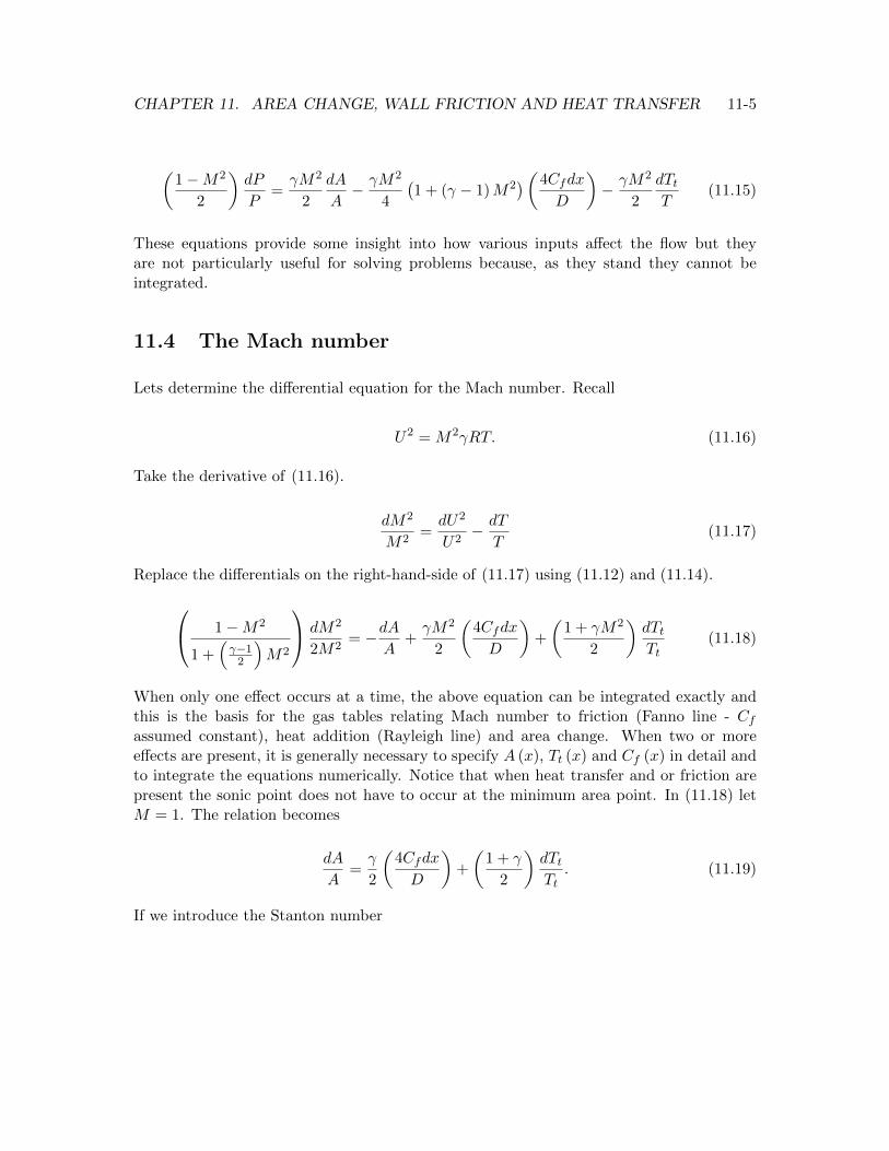
Recall that friction exerted by a no-slip wall at rest does not a↵ect the stagnation enthalpy.The various Fanno line relations (11.28) and (11.31) are plotted in Figure 11.2 for � =1.4.
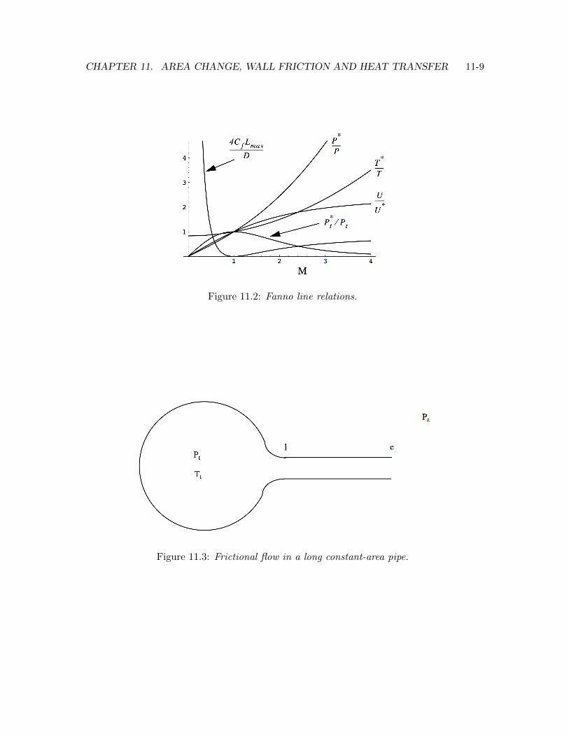
11.6.2 Example - frictional flow in a long pipe
Figure 11.3 shows air at constant stagnation pressure and temperature, Pt, Tt exhaustingfrom a very large plenum to the surrounding atmosphere through a long straight pipe. Thegas temperature in the plenum is Tt = 300K and Pt/Pa = 10.
CHAPTER 11. AREA CHANGE, WALL FRICTION AND HEAT TRANSFER 11-9
Figure 11.2: Fanno line relations.
Figure 11.3: Frictional flow in a long constant-area pipe.

CHAPTER 11. AREA CHANGE, WALL FRICTION AND HEAT TRANSFER 11-10
The friction coe�cient in the pipe is Cf = 0.01 and the pipe is 10 diameters long.
1) Determine the Mach number at the entrance to the pipe M1
.
Solution
Begin with the assumption that the flow is choked at the exit. Solve for M1
using (11.28).The result is
4CfLmax
D= 0.4 ) M
1
= 0.625. (11.32)
2) Determine Pte/Pt and Pe/Pa.
Solution
The Fanno line relations (11.31) give the stagnation pressure drop along the pipe.
Pte
Pt= 0.862 (11.33)
Alternatively, we could get the same result using (11.25) evaluated at the entrance andexit of the pipe where the Mach numbers are known. Thus at the pipe exit
Pte
Pa= 10⇥ 0.862 = 8.62. (11.34)
Since the exit Mach number is one
Pte
Pe=
✓� + 1
2
◆ ���1
= 1.23.5 = 1.893 (11.35)
and the static pressure ratio at the exit is
Pe
Pa=
8.62
1.893= 4.554. (11.36)
The fact that the exit static pressure comes out so much larger than the ambient, solidlyconfirms our assumption that the exit is choked.
3) Suppose the pipe is lengthened. What value of L/D will produce Pe/Pa = 1?
Solution
CHAPTER 11. AREA CHANGE, WALL FRICTION AND HEAT TRANSFER 11-11
At this condition the exit is choked, Me = 1 and the exit pressure is no longer above theambient pressure, that is Pe = Pa. Note the identity
Pe
Pa=
✓Pt
Pa
◆✓Pte
Pt
◆✓Pe
Pte
◆. (11.37)
The condition Pe/Pa = 1 implies that the stagnation pressure drop along the pipe mustbe
1 = 10
✓Pte
Pt
◆1
1.893) Pte
Pt=
1.893
10=
1
5.28. (11.38)
From the Fanno line stagnation pressure relation in (11.31) we find that this stagnationpressure ratio corresponds to M
1
= 0.11. Using this entrance Mach number (11.28) givesthe length of the pipe.
4CfLmax
D= 54.32 (11.39)
The value of L/D that unchokes the exit is
L
D=
54.32
4⇥ 0.01= 1358. (11.40)
11.6.3 Integrated relations - 1-D frictionless, constant area flow withheat transfer (Rayleigh line flow)
In the presence of heat transfer, the relationship between Mach number and stagnationtemperature from (11.18) is
dTt
Tt=
✓1�M2
1 + �M2
◆ 1
1 + ��1
2
M2
!dM2
M2
. (11.41)
Let the final state correspond to M = 1.
Z T ⇤t
Tt
dTt
Tt=
Z1
M2
✓1�M2
1 + �M2
◆ 1
1 + ��1
2
M2
!dM2
M2
(11.42)
Carry out the integration indicated in (11.42).

CHAPTER 11. AREA CHANGE, WALL FRICTION AND HEAT TRANSFER 11-12
T ⇤t
Tt=
�1 + �M2
�2
2 (1 + �)M2
⇣1 + ��1
2
M2
⌘ (11.43)
The stagnation temperature change required for the flow to pass from a given initial Machnumber M
1
to a final Mach number, M2
is found from
Tt2
Tt1=
✓Tt
T ⇤t
◆
M2
✓T ⇤t
Tt
◆
M1
. (11.44)
In each of the following relations
✓1�M2
2
◆dU2
U2
=dTt
T
✓1�M2
2
◆d⇢
⇢= �1
2
dTt
T
(11.45)
and
✓1�M2
2
◆dT
T=
✓1� �M2
2
◆dTt
T
✓1�M2
2
◆dP
P= �
✓�M2
2
◆dTt
T
(11.46)
replace dTt/Tt with��1�M2
�/�1 + ((� � 1) /2)M2
��dM2/
��M4
�and carry out the in-
tegration. The result is the set of Rayleigh line relations.
U
U⇤ =(� + 1)M2
1 + �M2
=⇢⇤
⇢
T ⇤
T=
✓1 + �M2
(� + 1)M
◆2
P ⇤
P=
1 + �M2
� + 1
P ⇤t
Pt=
✓1 + �M2
� + 1
◆ �+1
2
1 + ��1
2
M2
! ���1
(11.47)
CHAPTER 11. AREA CHANGE, WALL FRICTION AND HEAT TRANSFER 11-13
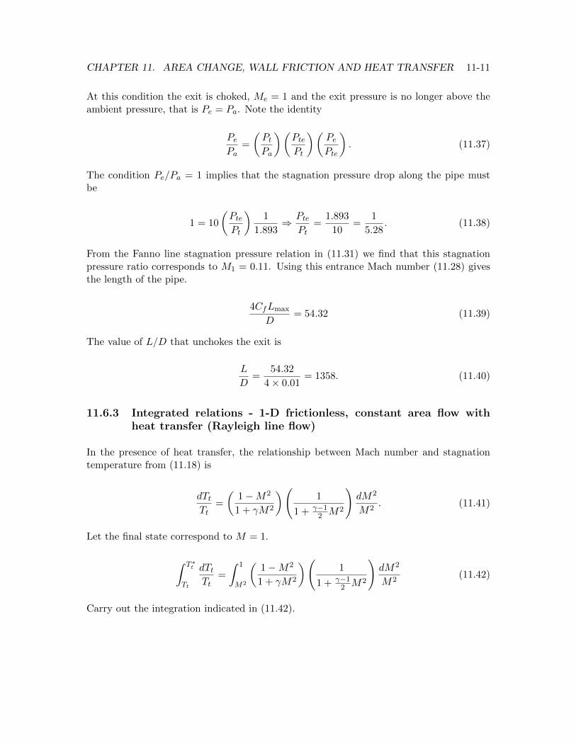
The various Rayleigh line relations (11.42) and (11.47) are plotted below for � = 1.4.
Figure 11.4: Rayleigh line relations.
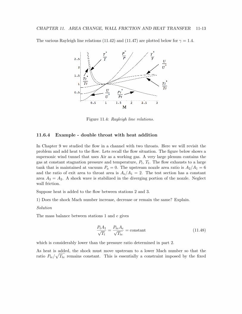
11.6.4 Example - double throat with heat addition
In Chapter 9 we studied the flow in a channel with two throats. Here we will revisit theproblem and add heat to the flow. Lets recall the flow situation. The figure below shows asupersonic wind tunnel that uses Air as a working gas. A very large plenum contains thegas at constant stagnation pressure and temperature, Pt, Tt. The flow exhausts to a largetank that is maintained at vacuum Pa = 0. The upstream nozzle area ratio is A
2
/A1
= 6and the ratio of exit area to throat area is Ae/A1
= 2. The test section has a constantarea A
3
= A2
. A shock wave is stabilized in the diverging portion of the nozzle. Neglectwall friction.
Suppose heat is added to the flow between stations 2 and 3.
1) Does the shock Mach number increase, decrease or remain the same? Explain.
Solution
The mass balance between stations 1 and e gives
PtA1pTt
=PteAep
Tte= constant (11.48)
which is considerably lower than the pressure ratio determined in part 2.
As heat is added, the shock must move upstream to a lower Mach number so that theratio Pte/
pTte remains constant. This is essentially a constraint imposed by the fixed
CHAPTER 11. AREA CHANGE, WALL FRICTION AND HEAT TRANSFER 11-14
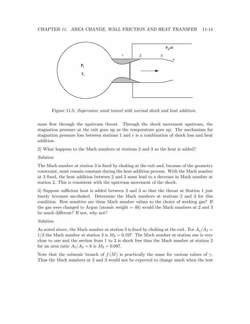
Figure 11.5: Supersonic wind tunnel with normal shock and heat addition.
mass flow through the upstream throat. Through the shock movement upstream, thestagnation pressure at the exit goes up as the temperature goes up. The mechanism forstagnation pressure loss between stations 1 and e is a combination of shock loss and heataddition.
2) What happens to the Mach numbers at stations 2 and 3 as the heat is added?
Solution
The Mach number at station 3 is fixed by choking at the exit and, because of the geometryconstraint, must remain constant during the heat addition process. With the Mach numberat 3 fixed, the heat addition between 2 and 3 must lead to a decrease in Mach number atstation 2. This is consistent with the upstream movement of the shock.
3) Suppose su�cient heat is added between 2 and 3 so that the throat at Station 1 justbarely becomes un-choked. Determine the Mach numbers at stations 2 and 3 for thiscondition. How sensitive are these Mach number values to the choice of working gas? Ifthe gas were changed to Argon (atomic weight = 40) would the Mach numbers at 2 and 3be much di↵erent? If not, why not?
Solution
As noted above, the Mach number at station 3 is fixed by choking at the exit. For Ae/A3
=1/3 the Mach number at station 3 is M
3
= 0.197. The Mach number at station one is veryclose to one and the section from 1 to 2 is shock free thus the Mach number at station 2for an area ratio A
1
/A2
= 6 is M2
= 0.097.
Note that the subsonic branch of f (M) is practically the same for various values of �.Thus the Mach numbers at 2 and 3 would not be expected to change much when the test

CHAPTER 11. AREA CHANGE, WALL FRICTION AND HEAT TRANSFER 11-15
gas is changed from air � = 7/5 to argon � = 5/3. The factor ((� + 1) /2)((�+1)/(2(��1)))
out in front of f (M) evaluates to 1.893 for � = 1.4 versus 1.77 for � = 1.66.
4) Recall the relationship between stagnation pressure loss and heat addition. Arguewhether the stagnation pressure loss between stations 2 and 3 is large or small?
Solution
At the point where the upstream throat barely chokes, the Mach number at station 2 isM
2
= 0.097. The stagnation pressure loss between stations 2 and 3 is proportional tothe Mach number squared and would be expected to be very small. To a pretty decentapproximation at this Mach number, Pte
⇠= Pt.
5) At approximately what ratio of Tte/Tt does the un-choking of the throat at station 1occur?
Solution
Since there is no shock and the heat addition takes place at low Mach number and weare asked for an approximate result, the stagnation temperature ratio at which the flowun-chokes can be determined from the mass flow balance.
A1pTt
=AepTte
) Tte
Tt= 4 (11.49)
11.7 Detonations and deflagrations
To complete this chapter, we will consider an important class of 1-D flows with heataddition where the source of heat is a combustible gas mixture of fuel and oxidizer. The1-D governing equations are
d (⇢U) = 0
d�P + ⇢U2
�= 0
d
✓CpT +
1
2U2
◆= �q
(11.50)
The flows governed by these equations are characterized by waves that combine the featuresof shock waves and heat addition. Consider a channel filled with a combustible mixture asshown in 11.6.

CHAPTER 11. AREA CHANGE, WALL FRICTION AND HEAT TRANSFER 11-16
Figure 11.6: Compression waves created by a source of ignition in a combustible mixture.
Upon ignition with a spark, the subsequent process of heat release and expansion of hotgases is energetic enough to produce pressure disturbances that propagate along the tubeaway from the source forming a self-sustaining combustion wave. One of two things mayhappen.
1) A weak deflagration wave may occur in which heat is transferred to the upstream gas byconduction. In this case the wave speed is generally very low, a few tens of centimeters persecond for hydrocarbon-air mixtures up to some tens of meters per second for a mixtureof hydrogen and oxygen. The speed of the wave cannot be determined from the heat ofreaction and jump conditions alone. It can only be determined by a model that treats thedetails of the wave and includes the e↵ects of heat conduction and viscosity. This is thesort of combustion wave one observes when a gas flame on a stove is ignited.
2) If the reaction is su�ciently energetic and heat loss mechanisms such as radiation andconduction to the channel walls are su�ciently small then the pressure waves precedingthe flame front can catch up to one another in a process of non-linear steepening dueto the dependence of acoustic speed on gas temperature. The steepening of the pressurefront quickly forms a shock wave. The shock preheats the unburned gas passing throughit causing the reaction to proceed at an even faster rate. Eventually the flow behind thecombustion wave becomes thermally choked and the shock-combustion wave combination,called a detonation, moves along the pipe at an extreme speed on the order of thousandsof meters per second. In this case the wave speed can be determined from the heat ofreaction and the jump conditions across a region of heat addition.
Figure 11.7 somewhat artificially decomposes the detonation into a conventional shockfollowed by a thermally choked region of heat addition called a strong deflagration. De-pending on the speed of the reaction and the mean free path of the gas, the whole regionof change is extremely thin (a fraction of a millimeter) and the intermediate zone a is anidealization of a state that only exists at one point in the wave if at all. The equations ofmotion can be integrated to form the jump conditions

CHAPTER 11. AREA CHANGE, WALL FRICTION AND HEAT TRANSFER 11-17
Figure 11.7: Chapman-Jouget detonation wave structure.
⇢1
U1
= ⇢2
U2
P1
+ ⇢1
U1
2 = P2
+ ⇢2
U2
2
CpT1
+1
2U1
2 +�ht = CpT2
+1
2U2
2
P = ⇢RT
(11.51)
where �ht is the stagnation enthalpy change per unit mass across the wave. Now we needto determine the possible states of motion that can occur and the Mach number of thewave for a given enthalpy change. First combine the mass and momentum equation toform the equation
✓P2
P1
� 1
◆= �M2
1
✓1� ⇢
1
⇢2
◆. (11.52)
The energy equation can be rearranged to read

CHAPTER 11. AREA CHANGE, WALL FRICTION AND HEAT TRANSFER 11-18
1
2
U2
1
CpT1
+ 1 +�htCpT1
=T2
T1
+1
2
✓⇢1
⇢2
◆2 U2
1
CpT1
(11.53)
or
✓1 +
�htCpT1
◆+
✓� � 1
2
◆M2
1
1�
✓⇢1
⇢2
◆2
!=
✓P2
P1
◆✓⇢1
⇢2
◆. (11.54)
Use (11.52) to eliminate M1
in (11.54). The result is
✓P2
P1
� 1
◆=
2�
� � 1
0
@�htCpT
1
+⇣1� ⇢
1
⇢2
⌘
⇣�+1
��1
⌘⇢1
⇢2
� 1
1
A . (11.55)
Equations (11.52) and (11.55) are two functions relating pressure and density that are bothsatisfied simultaneously and fully define the state of the gas.
P2
P1
� 1 = F
✓�,
⇢1
⇢2
,M1
◆
P2
P1
� 1 = G
✓�,
⇢1
⇢2
,�htCpT1
◆ (11.56)
If �ht/CpT1
= 0 (11.55) reduces to the Hugoniot relation for a normal shock. Equating(11.52) and (11.55) leads to a quadratic equation for ⇢
1
/⇢2
the roots of which are
⇢1
⇢2
=1 + �M2
1
±⇣�
M2
1
� 1�2 � 2 (� + 1)M2
1
�htCpT
1
⌘1/2
(� + 1)M2
1
. (11.57)
For �ht/CpT1
= 0 the roots are ⇢1
/⇢2
=�1,�2 + (� � 1)M2
1
�/�(� + 1)M2
1
��which are
the normal shock wave values. Note that the upstream Mach number M1
may be eithersubsonic or supersonic. A cross-plot of (11.52) and (11.55) will define the state of the gasfor a given �ht/CpT1
. Several di↵erent types of combustion waves can occur.
1) A weak deflagration where M1
< 1 and M2
< 1.
2) A strong deflagration or thermally choked wave where M1
< 1 and M2
= 1.
3) A weak detonation where M1
> 1 and M2
< 1.

CHAPTER 11. AREA CHANGE, WALL FRICTION AND HEAT TRANSFER 11-19
4) A thermally choked detonation where M1
> 1 and M2
= 1. This is also called aChapman-Jouget detonation. Virtually all stable detonations are of Chapman-Jouget type.In this case the wave can be decomposed into a shock wave and a strong deflagration asshown in figure 11.7.
The Mach number of a Chapman-Jouget wave for a given value of �ht/CpT1
can be deter-mined using the Rayleigh line equation for stagnation temperature change. Note that
�htCpT1
=
✓Tt2
Tt1� 1
◆Tt1
T1
. (11.58)
Now substitute (11.43) into (11.58) to get
�htCpT1
=
0
@�1 + �M2
1
�2
2 (� + 1)M2
1
⇣1 + ��1
2
M2
1
⌘ � 1
1
A✓1 +
� � 1
2M2
1
◆(11.59)
or
�htCpT1
=
�1�M2
1
�2
2 (� + 1)M2
1
. (11.60)
Solve Equation (11.60) for the Mach number.
M2
1
=
✓1 + (� + 1)
�htCpT1
◆± ✓
1 + (� + 1)�htCpT1
◆2
� 1
!1/2
(11.61)
The subsonic and supersonic roots of (11.61) are plotted below.
Figure 11.8: Mach number of a detonation wave determined by heat release.
CHAPTER 11. AREA CHANGE, WALL FRICTION AND HEAT TRANSFER 11-20
11.7.1 Example - detonation in a mixture of fluorine and hydrogen di-luted by nitrogen.
As an example, consider a stoichiometric mixture of 5% H2
and 5% F2
in90% N2
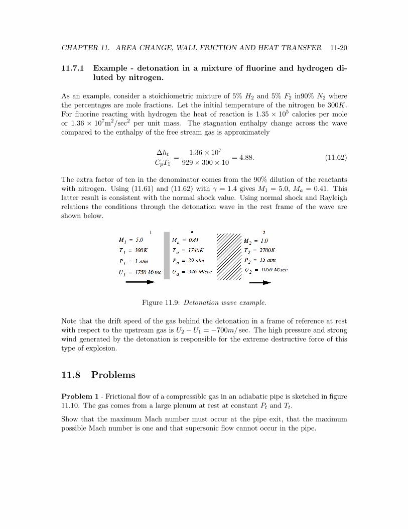
wherethe percentages are mole fractions. Let the initial temperature of the nitrogen be 300K.For fluorine reacting with hydrogen the heat of reaction is 1.35 ⇥ 105 calories per moleor 1.36 ⇥ 107m2/sec2 per unit mass. The stagnation enthalpy change across the wavecompared to the enthalpy of the free stream gas is approximately
�htCpT1
=1.36⇥ 107
929⇥ 300⇥ 10= 4.88. (11.62)
The extra factor of ten in the denominator comes from the 90% dilution of the reactantswith nitrogen. Using (11.61) and (11.62) with � = 1.4 gives M
1
= 5.0, Ma = 0.41. Thislatter result is consistent with the normal shock value. Using normal shock and Rayleighrelations the conditions through the detonation wave in the rest frame of the wave areshown below.
Figure 11.9: Detonation wave example.
Note that the drift speed of the gas behind the detonation in a frame of reference at restwith respect to the upstream gas is U
2
� U1
= �700m/ sec. The high pressure and strongwind generated by the detonation is responsible for the extreme destructive force of thistype of explosion.
11.8 Problems
Problem 1 - Frictional flow of a compressible gas in an adiabatic pipe is sketched in figure11.10. The gas comes from a large plenum at rest at constant Pt and Tt.
Show that the maximum Mach number must occur at the pipe exit, that the maximumpossible Mach number is one and that supersonic flow cannot occur in the pipe.

CHAPTER 11. AREA CHANGE, WALL FRICTION AND HEAT TRANSFER 11-21
Figure 11.10: Frictional flow in an adiabatic pipe.
Problem 2 - Natural gas, which is composed almost entirely of methane (molecular weight16, � = 1.3) is to be pumped through an insulated pipe one meter in diameter connectingtwo compressor stations 60 kilometers apart. At the upstream station, the stagnationpressure is 7 atmospheres and the stagnation temperature is 300K. The mean frictioncoe�cient is Cf = 0.001. Calculate the maximum mass flow rate that can be pumpedthrough the pipe by the downstream station.
Problem 3 - In figure 11.11 Air flows from a large plenum through an adiabatic pipewith L/D = 100. The pressure ratio is Pt/Pa = 1.5 and the friction coe�cient is Cf =0.01.
Figure 11.11: Frictional flow in an adiabatic pipe with given parameters.
Determine M1
, Me and Pte/Pt.
Problem 4 - In figure 11.12 a heater is used to increase the stagnation temperatureof a compressible flow of air exhausting from a large plenum at constant Pt and Tt tovacuum.
Figure 11.12: Flow in a constant area pipe with heat addition.
1) When Tte/Tt is increased does M1
increase, decrease or remain the same ?

CHAPTER 11. AREA CHANGE, WALL FRICTION AND HEAT TRANSFER 11-22
2) Consider the case where the increase in stagnation temperature is very large, Tte/Tt >>1. What is the value of Pte/Pt in this case?
Problem 5 - Figure 11.13 shows air at constant stagnation pressure and temperature,Pt, Tt exhausting from a very large plenum to the surrounding atmosphere through a longstraight pipe surrounded by a heater.
Figure 11.13: Flow in a constant area pipe with heat addition and friction neglected.
The gas temperature in the plenum is Tt = 300K and Pt/P0
= 10. The heater increasesthe stagnation temperature to Tte = 400K. Neglect the e↵ects of friction.
1) Determine the Mach number at the entrance to the pipe.
2) Determine Pte/Pt and Pe/P0
. Recall (11.25).
3) Suppose the amount of heat added is increased. What value of Tte, if any, will producePe/P0
= 1?
Problem 6 - The figure below shows a supersonic wind tunnel supplied with CarbonDioxide ( � = 4/3, Molecular weight = 44 ) from a very large plenum. The CO
2
passesthrough the test section and exhausts to a large vacuum chamber, Pa = 0. A high power,infrared laser tuned to one of the absorption lines of CO
2
is used to heat the gas betweenstations 2 and 3.
Relevant areas are Ae/A1
= 3, A2
= A3
, A2
/A1
= 5. Neglect wall friction.
1) The laser is initially turned o↵ and supersonic flow is established in the test section.Determine M
2
and Me.
2) The laser is turned on and the stagnation temperature is increased slightly between 2and 3 so that Tt3/Tt2 = 1.01. Determine M
2
. Estimate Pt3/Pt2 and Me.
3) How much stagnation temperature increase can occur between stations 2 and 3 beforethe wind tunnel un-starts?

CHAPTER 11. AREA CHANGE, WALL FRICTION AND HEAT TRANSFER 11-23
Figure 11.14: Supersonic wind tunnel with two throats and heat addition by laser absorption.
4) Suppose the stagnation temperature increase between stations 2 and 3 is such thatTt3/Tt2 = 4. Determine Pte/Pt.
Problem 7 - Include the e↵ects of friction and heat addition in a problem similar toProblem 2. The gas temperature in the plenum is Tt = 300K and Pt/P0
= 10. The exitstagnation temperature Tte is not specified, rather a model for the wall temperature willbe specified and Tte will be determined for a given length of pipe. Let Cf = 0.01 andL/D = 10. The di↵erential change in stagnation temperature in terms of the Stantonnumber is
dTt
Tt=
✓Twall
Tt� 1
◆✓4Stdx
D
◆. (11.63)
To solve the problem you will need the constant area Mach number relation
0
@ 1�M2
1 +⇣��1
2
⌘M2
1
A dM2
2M2
=�M2
2
✓4Cfdx
D
◆+
✓1 + �M2
2
◆✓Twall
Tt� 1
◆✓4Stdx
D
◆.
(11.64)
Let the wall temperature be distributed such that
Twall
Tt= 3 (11.65)
all along the wall.
1) Use (11.63) to determine Tte .

CHAPTER 11. AREA CHANGE, WALL FRICTION AND HEAT TRANSFER 11-24
2) Use the Reynolds analogy (11.10) and integrate (11.64) to determine the Mach numberat the entrance to the pipe.
3) Use mass conservation in the form of (11.25) to determine the stagnation pressure ratioacross the pipe and confirm that the exit flow is choked.
4) What value of L/D (if any) would cause the exit flow to un-choke?
Problem 8 - Consider the frictionless flow of a calorically perfect gas in a channel withheat addition. The wall is shaped so as to keep the static pressure constant. The flowenters at condition 1 and departs at condition 2. Let the ratio of stagnation temperaturebetween the entrance and exit be ⌧ = Tt2/Tt1.
(a) Find an expression for M2
in terms of �, M1
and ⌧ .
(b) Show that
A2
A1
= ⌧ +� � 1
2M2
1
(⌧ � 1) . (11.66)
(c) Show that
Pt2
Pt1=
⌧
⌧ + ��1
2
M2
1
(⌧ � 1)
!�/(��1)
. (11.67)
Problem 9 - Plot the temperature versus entropy of a calorically perfect gas in a constantarea flow with friction. This is done by creating a chart of temperature versus Mach numberand a chart of entropy versus Mach number. When the two variables are plotted versusone another with the Mach number as a parameter along the trajectory (ranging, say, fromzero to 4), the resulting curve is called the Fanno line. Repeat the process for the case ofconstant area flow with heat transfer to produce the Rayleigh line.
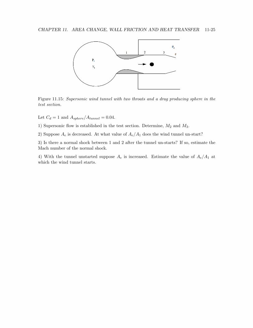
Problem 10 - Figure 11.15 shows a supersonic wind tunnel supplied with Air from a verylarge plenum. The air passes through the test section and exhausts to a large vacuumchamber, Pa = 0. A sphere is placed in the test section between stations 2 and 3. Thetunnel and sphere are adiabatic. The e↵ect of wall friction on the flow can be neglectedcompared to the e↵ect of the drag of the sphere.
Relevant areas are A2
/A1
= 5, A2
= A3
and Ae/A1
= 3. A reasonable model for thestagnation pressure drop due to the sphere is
Pt3
Pt2= 1� �M2
2
2
✓Asphere
Atunnel
◆Cd. (11.68)
CHAPTER 11. AREA CHANGE, WALL FRICTION AND HEAT TRANSFER 11-25
Figure 11.15: Supersonic wind tunnel with two throats and a drag producing sphere in thetest section.
Let Cd = 1 and Asphere/Atunnel = 0.04.
1) Supersonic flow is established in the test section. Determine, M2
and M3
.
2) Suppose Ae is decreased. At what value of Ae/A1
does the wind tunnel un-start?
3) Is there a normal shock between 1 and 2 after the tunnel un-starts? If so, estimate theMach number of the normal shock.
4) With the tunnel unstarted suppose Ae is increased. Estimate the value of Ae/A1
atwhich the wind tunnel starts.