Embed Size (px)
Citation preview
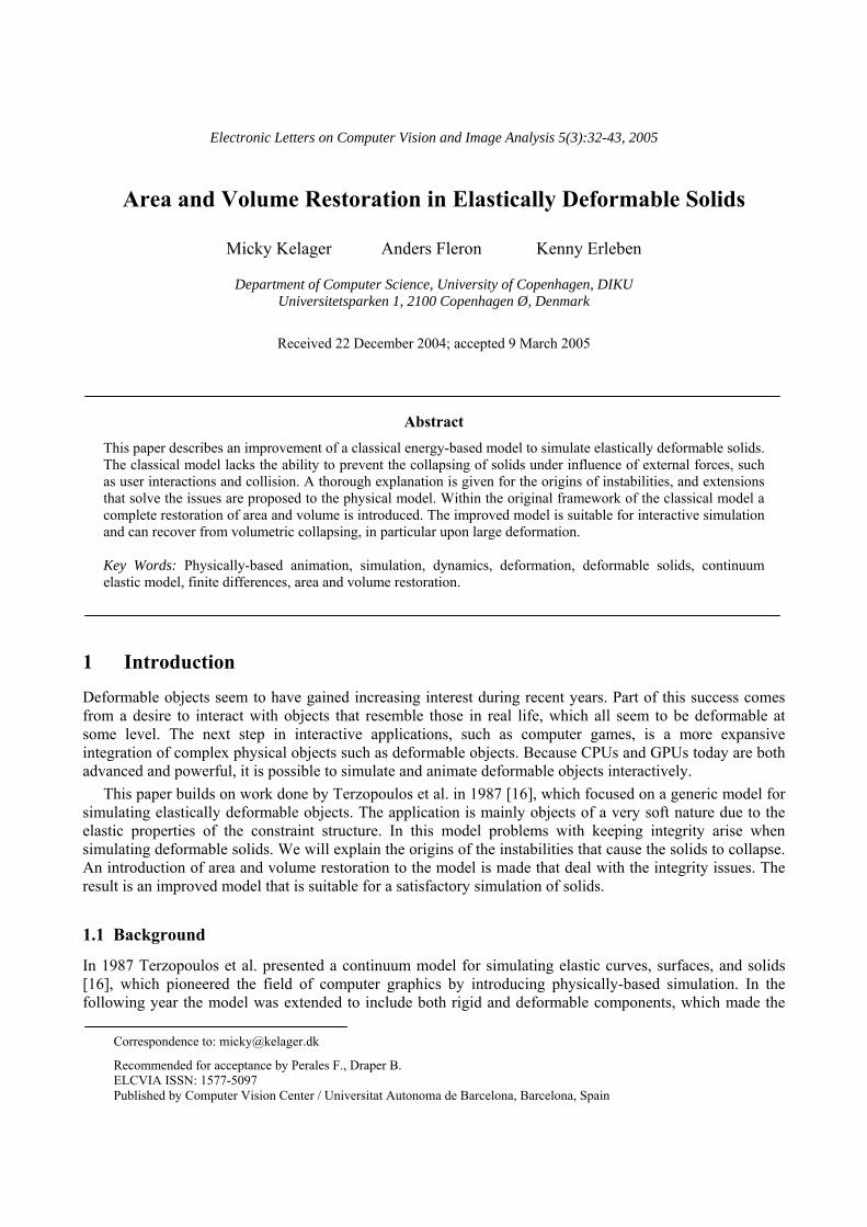
Electronic Letters on Computer Vision and Image Analysis 5(3):32-43, 2005
Area and Volume Restoration in Elastically Deformable Solids
Micky Kelager Anders Fleron Kenny Erleben
Department of Computer Science, University of Copenhagen, DIKU Universitetsparken 1, 2100 Copenhagen Ø, Denmark
Received 22 December 2004; accepted 9 March 2005
Abstract This paper describes an improvement of a classical energy-based model to simulate elastically deformable solids. The classical model lacks the ability to prevent the collapsing of solids under influence of external forces, such as user interactions and collision. A thorough explanation is given for the origins of instabilities, and extensions that solve the issues are proposed to the physical model. Within the original framework of the classical model a complete restoration of area and volume is introduced. The improved model is suitable for interactive simulation and can recover from volumetric collapsing, in particular upon large deformation.
Key Words: Physically-based animation, simulation, dynamics, deformation, deformable solids, continuum elastic model, finite differences, area and volume restoration.
1 Introduction Deformable objects seem to have gained increasing interest during recent years. Part of this success comes from a desire to interact with objects that resemble those in real life, which all seem to be deformable at some level. The next step in interactive applications, such as computer games, is a more expansive integration of complex physical objects such as deformable objects. Because CPUs and GPUs today are both advanced and powerful, it is possible to simulate and animate deformable objects interactively.
This paper builds on work done by Terzopoulos et al. in 1987 [16], which focused on a generic model for simulating elastically deformable objects. The application is mainly objects of a very soft nature due to the elastic properties of the constraint structure. In this model problems with keeping integrity arise when simulating deformable solids. We will explain the origins of the instabilities that cause the solids to collapse. An introduction of area and volume restoration to the model is made that deal with the integrity issues. The result is an improved model that is suitable for a satisfactory simulation of solids.
1.1 Background
In 1987 Terzopoulos et al. presented a continuum model for simulating elastic curves, surfaces, and solids [16], which pioneered the field of computer graphics by introducing physically-based simulation. In the following year the model was extended to include both rigid and deformable components, which made the
Correspondence to: [email protected]
Recommended for acceptance by Perales F., Draper B. ELCVIA ISSN: 1577-5097 Published by Computer Vision Center / Universitat Autonoma de Barcelona, Barcelona, Spain

33 Kelager et al. / Electronic Letters on Computer Vision and Image Analysis 5(3):32-43, 2005
objects appear less elastic [17]. Concepts such as viscoelasticity, plasticity, and fracture were also added into the model [15].
In [1] a modified Conjugate Gradient method with integrated contact forces is used to increase performance with collision handling. In [18] energy-based preservation of distance, surface area, and volume were introduced, which is similar to the way we use area and volume restoration in this paper.
In the area of geometrical approaches Provot used a relaxation-based method back in 1995 [13] to solve a system of constraints, and gained significant performance improvements. In [2] the relaxation-based method was introduced into in the impulse-based domain. In [7, 20] the iterative SHAKE and RATTLE methods from molecular dynamics were introduced into the area of physically-based simulation and animation. Both methods are based on the Verlet integration scheme.
For better visual results of large deformations, stiffness warping [10] was used to separate the rotational element from the deformable motion. The stiffness warping method was extended in [11] to include plasticity, fracture, and a new method for cracking in a coupled mesh.
In [6] integrity problems upon large deformations were handled by using a finite element method. It was done by using a diagonalization procedure within the tetrahedral mesh, which meant that the method could handle extreme cases such as inverted elements. This resembles the volume restoring technique that we are using in this paper.
1.2 Motivation
The physically-based model for simulating elastically deformable objects, presented in [16], is capable of describing deformable curves, surfaces and volumes. The method is still of interest today because it is firmly based on Newtonian mechanics. Many recent methods primarily use geometry-based procedures to achieve performance when imitating the complex behavior of deformable objects [10, 18, 11]. Physically accurate models convey a more believable behavior and with the increase in processing power they become more relevant.
The integrity problems that are inherent in the original model make it unsuitable for simulating deformable solids in practice. Restoration of integrity is important to give a realistic impression to people who interact with them. With the restoration the objects will be forced to seek toward their original volume size. This should not be confused with volume preservation, which insures that the overall volume of the object never changes. The extensions are achieved by using concepts from the framework of the original model, with the price of a constant increase of calculations per particle.
1.3 Overview
In section 2 we revisit the theory of elastically deformable models, with focus on solids. The theory serves as a foundation for understanding the following sections. Section 3 reveals and explains the instabilities of the classical model. In section 4 we introduce our improvements to area and volume restoration, and in section 5 we extend the model with the ability to resist collapsing. In section 6 we present the results of our improvements and perform comparisons visually between the improved and the classical model.
2 Elastically Deformable Solids The theory of deformable models is based on elasticity theory. From physical laws [16] have extrapolated a model that governs the movements of elastically deformable objects.
A point in a solid is described by the intrinsic coordinates . A deformable solid is thought of as having a natural rest state, where no elastic energy is inherent. When the solid is deformed, it takes on a different shape than its rest shape, and distances between nearby points are either stretched or compressed with the deformation. This ultimately creates elasticity that results in internal forces that will seek to minimize the elastic energy. The deformation will evolve over time and can be described by the time-varying
1 2 3[ , , ]a a a=a

Kelager et al. / Electronic Letters on Computer Vision and Image Analysis 5(3):32-43, 2005 34
positional vector function ( ) ( ) ( ) ( )[ ]1 2 3, , , , ,t r t r t r t=r a a a a, , which is defined in 3-dimensional Euclidian space. The evolving deformation is independent of the rigid body motion of the solid. The equations governing the motion of particles in a deformable solid are obtained from Newtonian mechanics, and given by
( ) ( ), t
t t tδε
µ γδ
∂ ∂ ∂+ + =
∂ ∂ ∂⎛ ⎞⎜ ⎟⎝ ⎠
rr rf r
r, (1)
where is the position of the particle, , at time t , ( ), tr a a ( )µ a is the mass density, ( )γ a is the damping density, and the right hand side represents the sum of externally applied forces. The third term on the left hand side of (1) is called a variational derivative and represents the internal elastic energy. ( )ε r is a functional that measures the potential energy that builds up when the solid is deformed.
2.1 Energy of Deformation
A method is needed to measure the deformation energies that arise when a solid deforms. For this task, we use differential geometry. It is convenient to look at arc-lengths on curves, running along the intrinsic directions of the solid. A way of measuring the directions is specified by the metric tensor also known as the first fundamental form
( )( ) , 1 , 3iji j
Ga a∂ ∂
i j= ⋅ ≤∂ ∂
r rr a ≤
)G
, (2)
which is a symmetric tensor. The diagonal of the tensor represents length measurements along the coordinate directions from the particle in question. The off-diagonal elements represent angle measurements between the coordinate directions. When measuring deformation energy in a solid, we are interested in looking at the change of the shape, with respect to the natural rest shape, which is described by . The energy of
deformation, , can be described by the weighted Hilbert-Schmidt matrix norm of the difference between the metric tensors in the deformed and rest states
0
ijG
( )ε r
where (3) ( ) ( )( ) 1 2 3, ,S t da da daεΩ
= ∫r r a ( ) (3 20
, 1
,ij ij iji j
S Gη=
= −∑r
where is the domain of the deformable solid and is a user defined tensor that weights each of the coefficients of the metric. By using the Euler-Lagrange equation from variational calculus on
Ω η
( )S r in (3) a minimizing term for the energy is obtained
(3
, 1
,i ja ij a
i j
Sδα
δ =
= − ∂∑ rr ) where ( )0
i jij ij a a ijGα η= ⋅ −r r . (4)
The -tensors represent the comparison between the deformed state and the rest state of the solid. When an element in α becomes positive, it means that the corresponding constraint has been stretched and it converges to its rest length by shrinking. Likewise, when an element becomes negative, the constraint has been compressed and it converges to its rest length by growing.
α
2.2 Discretization
The deformable object is continuous in the intrinsic coordinates. To allow an implementation of deformable solids, the object is discretized into a regular 3D grid structure, where grid nodes represent the particles which will make up a solid. The grid has three principal directions called l , , and n . Particles in the grid m

35 Kelager et al. / Electronic Letters on Computer Vision and Image Analysis 5(3):32-43, 2005
are uniformly distributed with spacings in each of the three directions, given by , , and . The number of particles in each of the directions are designated
1h 2h 3hL , M , and . N
The model requires that derivatives are calculated in the intrinsic directions of the object. For this purpose we use finite difference operations to achieve the desired derivative approximations [3]. Replacing the derivatives with the corresponding difference operators yields the discrete equation for the elastic force e
where [ ]3
, 1
, , ( )[ , , ],ii j
l m n D l m n−
=
= −∑e p [ ], , [ , , ] ( )[ , , ]ij jl m n l m n D l m nα +=p r , (5)
where the superscripts and designates forward and backward differences, respectively. The tensor field is also discretized using finite differencing
+ −α
[ ] [ ] ( )[ ] ( )[ ] [ ]( )0, , , , , , , , , ,ij ij i j ijl m n l m n D l m n D l m n G l m nα η + += ⋅ −r r . (6)
To solve the equations for all particles at the same time, the values in the positional grid, , and the energy grid, , can be unwrapped into -dimensional vectors,
re LMN r and e . With these vectors, the entire
system of equations can be written as
( )=e K r r , (7)
where ( )K r is an sized stiffness matrix, which has desirable computational properties such as sparseness and bandedness. We introduce the diagonal
LMN LMN×
LMN LMN× mass matrix , and damping matrix , assembled from the corresponding discrete values of and , respectively. The equations
of the elastically deformable objects (1) can now be expressed in grid vector form, by the coupled system of second-order ordinary differential equations
MC [ , , ]l m nµ [ , , ]l m nγ
( )2
2t t
∂ ∂+ +
∂ ∂
r rM C K r r = f . (8)
With these equations it is possible to implement real-time dynamic simulations of deformable solids. To evolve the solid through time we use the semi-implicit integration method described in [16]. The time derivatives in (8) can be approximated by second and first order central differencing [3]. Further more the desirable properties of the stiffness matrix indicate that a relaxation method, such as the conjugate gradient [14], can be utilized.
3 Instabilities
Notions from differential geometry are used as a tool to measure deformation of an elastic object. For solids the metric tensors are sufficient to distinguish between the shapes of two objects. However, the metric tensor of a solid is not sufficient to compute the complex particle movements of a deformed solid, seeking towards its resting shape. The discrete off-diagonal components of (2) are the cosine to the angle between directions through the dot product
3 3×
cos , 0θ θ π⋅ = ≤ ≤v w v w . (9)
The angle between two vectors is not dependent on their mutual orientation, as verified by the domain of θ in (9). This leads to problems with area restoration on the sides of grid cubes. Figure 1(a) illustrates this instability. The bold lines and the angle between them form the natural condition. If particle is moved towards particle , it will only be forced back towards its resting position when
AB 0 θ π< < , as depicted in
case 1. If 0θ π θ= ∨ = then the elastic force is ambiguously defined, as in case 2. If the particle reaches beyond the opposite diagonal, the elasticity will now push particle into , as illustrated in case 3. This is A B

Kelager et al. / Electronic Letters on Computer Vision and Image Analysis 5(3):32-43, 2005 36
clearly a problem, as it can reduce the surface into a curve. The original model [16] suffers from this instability.
(a) The surface patch will collapse to a curve, when a particle crosses the opposite
diagonal.
(b) Missing spatial diagonal constraint.
Figure 1: Constraint instabilities.
Internal constraints are enforced by comparing the deformed and undeformed metric tensors, which means that the model only looks at distances and angles between adjacent particles. As a result of the lack of spatial constraints, as depicted on Figure 1(b), volumetric instability issues arise. This leads to problems with solids not being able to restore their original volume. It turns out that the volume restoration problem is more significant than the problem with area restoration, and has a bigger impact on object integrity.
4 Improvements To handle the integrity instabilities of the discrete grid cubes we extend the elasticity constraints in order to improve their ability to prevent collapsing. Basically, the extension will be done by both replacing and adding new constraints. The metric tensor is redesigned to stabilize the area restoration while we introduce a new spatial diagonal metric to handle volume restoration.
4.1 Improved Area Restoration
Area restoration concerns 2 dimensions, thus in the following we will focus on the metric tensor for deformable surfaces. For a surface, the tension constraints on a given particle are the four constraints given by the comparison between its 2 metric tensors G and . The comparison between the diagonal elements defines the length constraints along the intrinsic coordinate directions. The comparison between the off-diagonal elements represents pairs of angular constraints between two intrinsic directions, which imply resistance to shearing within the local particle structure. Since the idea is to replace the pair of angular constraints with two diagonal length constraints. These constraints will reach from the particle at
to the diagonally opposite particles at [ 1
2× 0G
ij jiG G=
[ , ]m n , 1m n ]+ + and [ 1, 1m n ]− + , as depicted in Figure 2. The diagonal length constraints will implicitly work as angular constraints that can account for all degrees. The directions along the new constraints will be considered as new intrinsic directions, and . Writing
out in (3), for the case of surfaces, with the new directions yields
360
1da 2da( )S r

37 Kelager et al. / Electronic Letters on Computer Vision and Image Analysis 5(3):32-43, 2005
, (10) ( ) ( ) ( ) (1 1 2 2
20 0
12 12 21 211
i i d d d dii a a ii a a a ai
S G Gη η η=
= ⋅ − + ⋅ − + ⋅ −∑r r r r r r r )0G
r
where the elements and now holds the rest states of the new diagonal constraints. Using variational calculus on (10) results in the following discretization for the elastic force ,
0
12G 0
21Ge
, (11) 2
1 1 2 21
[ , ] ( )[ , ] ( )[ , ] ( )[ , ]i d di
m n D m n D m n D m n− − −
=
= − − −∑e p p p
where
(12) 1 12 1
2 21 2
[ , ] [ , ] ( )[ , ],[ , ] [ , ] ( )[ , ],[ , ] [ , ] ( )[ , ].
ii i
d
d
m n m n D m nm n m n D m nm n m n D m n
η
η
η
+
+
+
=
=
=
p rpp r
Notice that new difference operators arise with the new directions. These operators work exactly as the operators in the original directions. E.g. the new first order forward difference operators on the positional field becomes r
( ) [ ] [ ]( )1
1 1 1, 1 ,d dD h m n m n+ −= + + −r r r and ( ) [ ] [ ]( )12 2 1, 1 ,d dD h m n m n+ −= − + −r r r , (13)
where 2
1 2 1d dh h h h= = + 2
2 is the grid distance in both diagonal directions.
(a) Original metric tensor (b) Extended metric tensor
Figure 2: (a) The angular constraints are replaced by (b) two new diagonal constraints that will define the
angular constraints implicitly.
The replacements to the metric tensor will improve the area restoration. However, collapses, or folds, within discrete grid patches can occur if 12 21 11 22η η η η+ < + , thus choosing wisely is important. η
The improvements to the metric tensor for surfaces can likewise be applied to deformable solids in a straight forward manner. The off-diagonal elements of the 3 3× metric tensor contain pair-wise expressions of the angular constraints between two of the three directions. These pairs can each be replaced by two diagonal length constraints. The extended metric tensor for solids will now span area restoration in the three directions of a discrete grid cube. When the extended metric tensor is applied to all particles of the deformable solid, the result will be that all grid patches have gained the desired area restoration.

Kelager et al. / Electronic Letters on Computer Vision and Image Analysis 5(3):32-43, 2005 38
4.2 Volume Restoration
Area restoration can keep grid cube patches from collapsing. However, this is not always enough to keep the cubes from collapsing. If a particle is being forced along its spatial diagonal, the result of the area restoration will normally push the particle back to its relative point of origin. Yet, if the force is strong enough to push the particle beyond the center of the cube, the area restoration will still succeed, but the restoring of the grid patches will now push the particle further along the diagonal. This is an analogy to the instability problem discussed in section 3.
To implement volume restoration, we introduce the spatial diagonal metric, V , which is a tensor. The four elements of V represent length constraints that will be spatially diagonal, meaning they will span grid cubes volumetrically, as depicted in Figure 3(a).
2 2×
1 1 2 2
3 3 4 4
v v v v
v v v v
D D D DD D D D
+ + + +
+ + + +
⋅ ⋅≡
⋅ ⋅
⎡ ⎤⎢ ⎥⎣ ⎦
V , (14)
where are the four new first order forward difference operators along the new spatial diagonal directions. The spatial diagonal constraints can be chosen to favor any directions, as long as the contributions from the four particles on a grid cube patch will end up covering the cube symmetrically, as depicted in Figure 3(b).
( )1..4vD+ u
The difference operators are designed similarly to the two dimensional case in (13). To implement volume restoration into the model, the discrete elastic force must be extended to contain the contributions provided by the spatial diagonal metric. This can likewise be shown to be as straight forward as the addition of the extended metric tensor.
[ , , ]l m ne
(a) (b)
Figure 3: Spatial length constraints for solids. (a) The four constraints reach out from the center. (b) The constraint contribution from four particles on a single cube patch renders symmetric behavior.
5 Implosions With the improved area and volume restorations we can restore the shape of the discrete grid cubes after deformation. This is an important improvement towards keeping the integrity of a deformable solid intact. Another integrity issue still exists since a simulated solid is still unable to prevent implosions. We define an implosion as when grid cubes enter their adjacent grid cubes through non-mutual particles, as depicted in Figure 4(a). Implosions happen upon large deformation, which typically are caused by heavy external forces, e.g. reaction to collisions and aggressive user interactions. Implosions can also be described as internal self-intersections, thus self-intersection detection can be utilized as a tool to prevent implosions. For details on the area of self-intersection we recommend papers such as [5, 9, 19, 8].

39 Kelager et al. / Electronic Letters on Computer Vision and Image Analysis 5(3):32-43, 2005
We seek a mechanism that binds adjacent grid cubes together, in such a way that if implosions occur, we can disperse self-intersecting cubes. This is not a method that can prevent self-intersections, but it can restore the integrity of the solid upon implosions. We can reuse the constraint system that we have been working with so far, and thus reduce the computational cost and memory use significantly, compared to the extra load we would introduce into the system, if we had implemented a standard self-intersection detection algorithm.
We introduce the pillar tensor , which is based upon the discrete metric tensor G , but extended to use first order central difference operators. For reasons of clarity we will limit only to use the length constraints along the diagonal
PP
[ ]( )
( )( )
21
22
23
0 0, , 0 0
0 0
Dl m n D
D=
⎡ ⎤⎢ ⎥⎢ ⎥⎢ ⎥⎣ ⎦
rP r
r, (15)
where
( )[ ] ( ) [ ] [ ]( )( )[ ] ( ) [ ] [(( )[ ] ( ) [ ] [( )
1
1 1
1
2 2
1
3 3
, , 2 1, , 1, , ,
, , 2 , 1, , 1, ,
, , 2 , , 1 , , 1 .
])]
D l m n h l m n l m n
D l m n h l m n l m n
D l m n h l m n l m n
−
−
−
= + − −
= + − −
= + −
u u u
u u u
u u u −
(16)
The effect of using central difference operators results in a convincing way to bind adjacent grid cubes together, see Figure 4(b). The pillar tensor is yet another addition to the extended elasticity term and is handled exactly the same way as the area and volume restorations. Since every grid particle will be extended with the contribution of the pillar tensor, the combined range of will overlap all grid cubes along the intrinsic directions. The effect of using the pillar tensor is that grid cubes will repel each other in situations of overlapping.
P
(a) Implosion. (b) Effect of central differences.
Figure 4: (a) Grid cube implosion is avoided using (b) Central differences that bind adjacent grid cubes
together.
In some cases of extreme external forces the pillar contribution is not enough to completely prevent grid cubes from overlapping. This is due to the sum of external forces is exceeding the internal elastic forces. One way to handle this is to strengthen the overall weight of the pillar tensor. However, as this can lead to numerical instabilities, the pillar tensor can implement the missing off-diagonal elements from the extended metric. To further prevent implosions an additional tensor can be added that implements a central difference spatial diagonal metric.
Kelager et al. / Electronic Letters on Computer Vision and Image Analysis 5(3):32-43, 2005 40
6 Results
We have implemented the original model from [16] with our improvements of area and volume restoration and with the simple prevention of implosion, as described in section 4 and 5, respectively. The implementation is publicly available from [4]. Experiments have revealed that the effects of the spatial diagonal metric do not always succeed satisfactorily in moving particles back to their natural location. In some situations new energy equilibriums arise unnaturally. We have realized that the constraints from the area restoration can work against the volume restoration. To counteract this problem, we have simply squared the constraint forces of the spatial diagonal metric tensors, to make sure they prevail. In general this means that volume restoration should have a higher precedence than area restoration, which in turn should have a higher precedence than distance restoration. Numerical instabilities tend to occur when too large parameter values are used, such as particle mass, time step, and constraint strength. This is likely a problem with the semi-implicit integrator.
We have performed visual comparisons between the original and our improved model to show the advantage of handling the integrity instabilities. In Figure 5, still frames of a small box that is influenced by gravity and collides with a plane are compared frame to frame between the two models. Primarily due to the lack of volume restoration, the constraints of the original model simply cannot keep the shape of the discrete grid cubes. In Figure 6 we compare two rubber balls with different particle mass. The rubber ball in Figure 6(a) is simulated using the original model and fails to maintain its integrity, thus the ball collapses on itself. The rubber ball in Figure 6(b) is simulated using the improved model with the same parameters, and the integrity of the ball is now strong enough to stay solid. In Figure 7, a test of how well the two models can recover from a sudden aggressive deformation is performed. The original model fails its attempt at complete recovery, whereas the improved model actually performs its recovery convincingly.
The improved model enables real-time simulation of situations that are impossible with the original model. In Figure 8, a soft solid is depicted. The solid has been constrained to the ground, and in three of the top corners. Pulling the free top corner downwards results in a large deformation and renders convincing material buckling. In Figure 9, the true strength of the pillar tensor contribution is illustrated, showing an effect of inflation. First the overall constraint strength is at a minimum and is then increased in the following frames. In Figure 10, a soft solid is constrained to the ground, and being twisted by its top face. The sides of the deformable solid skew as expected of a soft body like pudding. In Figure 11, a large water lily is deformed when resting on pearls. The improved model performs a great job in keeping the water lily fluffy.
7 Conclusion
The original model presented in [16] for simulating elastically deformable solids turned out to be insufficient for achieving realism. Even extremely modest external forces applied to the solids would ruin their integrity. In this paper we have shown how replacements to the metric tensor can be implemented to improve area restoration, and how to implement the missing volume restoration. Furthermore we have shown how to handle internal self-intersection using the framework from the original model. Even though the original model is dated back to 1987 it is still competitive in the field of physically-based simulation. Visual comparisons have revealed that our improvements to the model provide deformable solids with the ability to keep their integrity, and thus the ability to handle large deformations in real-time without collapsing. Our improved model is a viable alternative to other methods for simulating deformable solids.
Interesting challenges for future work include using unstructured meshes instead of the regular 3D grid. However, this will complicate the use of finite difference operators when approximating derivatives. Working with solids gives the occasion to use tetrahedral meshes and the finite element method. The problem of generating tetrahedral meshed from closed 2D manifolds can be solved using the approach described in [12]. The advantage of the regular grid approach, taken by this model, compared to using a tetrahedral mesh is that fewer elements are needed to represent the deformable solid. It is also possible that other integration procedures can perform better in terms of numerical stability and thus an analysis of this field might be beneficial.

41 Kelager et al. / Electronic Letters on Computer Vision and Image Analysis 5(3):32-43, 2005
References
[1] D. Baraff and A. Witkin. "Large Steps in Cloth Simulation". Proceedings of the Annual ACM SIGGRAPH'98 Conference, ACM Press, Vol. 33, pp. 43-54, 1998.
[2] R. Bridson, R. Fedkiw, and J. Anderson. "Robust Treatment of Collisions, Contact and Friction for Cloth Animation". In Proceedings of ACM SIGGRAPH 2002, pp. 594-603, 2002.
[3] D. Eberly. Derivative Approximation by Finite Differences. Magic Software, Inc., January 21, 2003, Online paper: http://www.magic-software.com/Documentation/FiniteDifferences.pdf[4] K. Erleben, H. Dohlmann, J. Sporring, and K. Henriksen. The OpenTissue project. Department of
Computer Science, University of Copenhagen, DIKU, November 2003, http://www.opentissue.org[5] B. Heidelberger, M. Teschner, and M. Gross. “Detection of Collisions and Self-collisions Using
Image-space Techniques”. In Proceeding of WSCG'04, University of West Bohemia, Czech Republic, pp. 145-152, 2004.
[6] G. Irving, J. Teran, and R. Fedkiw. "Invertible Finite Elements for Robust Simulation of Large Deformation". ACM SIGGRAPH/Eurographics Symposium on Computer Animation (SCA), pp. 131-140, 2004.
[7] T. Jakobsen. "Advanced character physics". In Proceedings of Game Developer’s Conference 2001, 2001.
[8] D. L. James and D. K. Pai. “BD-Tree: Output-Sensitive Collision Detection for Reduced Deformable Models”. In Proceedings ACM SIGGRAPH 2004, pp. 393-298, 2004.
[9] T. Larsson and T. Akenine-Möller. “Collision Detection for Continuously Deforming Bodies”. In Eurographics 2001, pp. 325-333, 2001.
[10] M. Müller, J. Dorsey, L. McMillan, R. Jagnow, and B. Cutler. “Stable Real-Time Deformations”. In Proceedings of ACM SIGGRAPH 2002, pp 49-54, 2002.
[11] M. Müller and M. Gross. "Interactive Virtual Materials". In Proceedings of Graphics Interface (GI 2004), pp 239-246, 2004.
[12] M. Müller and M. Teschner. Volumetric Meshes for Real-Time Medical Simulations. In Proceedings of BVM, pp. 279-283, 2003.
[13] Provot, X. "Deformation constraints in a mass-spring model to describe rigid cloth behavior". In Graphics Interface 1995, pp. 147–154, 1995.
[14] J. R. Shewchuk. An Introduction to the Conjugate Gradient Method Without the Agonizing Pain. Carnegie Mellon University, 1994.
[15] D. Terzopoulos and K. Fleischer. “Modeling Inelastic Deformation: Viscoelasticity, Plasticity, Fracture”. In Computer Graphics, Volume 22, Number 4, August 1988, pp. 269-278, 1988.
[16] D. Terzopoulos, J. C. Platt, A. H. Barr, and K. Fleischer. “Elastically deformable models”. Computer Graphics, volume 21, Number 4, July 1987, pp 205-214, 1987.
[17] D. Terzopoulos and A. Witkin. “Physically-Based Models with Rigid and Deformable Components”. In Proceedings of Graphics Interface ’88, pp.146-154, 1988.
[18] M. Teschner, B. Heidelberger, M. Müller, and M. Gross. “A Versatile and Robust Model for Geometrically Complex Deformable Solids”. In Proceedings of Computer Graphics International, June 16-19 2004, pp 312-319, 2004.
[19] G. van den Bergen. “Efficient Collision Detection of Complex Deformable Models using AABB Trees”. Journal of Graphics Tools 2(4), pp. 1–14, 1998.
[20] J. M. Wagenaar. Physically Based Simulation and Visualization, A particle-based approach. Ph.D. Thesis, The Mærsk Mc-Kinney Møller Institute for Production Technology, 2001.

Kelager et al. / Electronic Letters on Computer Vision and Image Analysis 5(3):32-43, 2005 42
(a)
(b)
Figure 5: A small box is influenced by gravity and collides with a plane. (a) The three stills illustrate the original model, and (b) the frames from the improved model are shown.
(a) (b)
Figure 6: Rubber balls. (a) Illustrates the situation from the original model, where the ball is unable to maintain its integrity, (b) the same situation is depicted, but simulated using the improved model.
(a) Original Model. (b) Improved Model.
Figure 7: A wooden box is heavily lifted in one corner.

43 Kelager et al. / Electronic Letters on Computer Vision and Image Analysis 5(3):32-43, 2005
Figure 8: Large deformation results in convincing material buckling.
Figure 9: Constraint strength is increased interactively and yields the effect of inflation.
Figure 10: Twisting the pudding renders skewing. Figure 11: Fluffy water lily modeled using an ellipsoid solid.