Embed Size (px)
Citation preview

Arduino Duemilanove Atmega328
Description:
The Arduino Duemilanove ("2009") is a microcontroller board based on the ATmega328. It has 14 digital input/output pins (of which 6 can be used as PWM outputs), 6 analog inputs, a 16 MHz crystal oscillator, a USB connection, a power jack, an ICSP header, and a reset button. It contains everything needed to support the microcontroller; simply connect it to a computer with a USB cable or power it with a AC‐to‐DC adapter or battery to get started. Note: doesn't contain usb‐cable necessary to program the Arduino Duemilanove. Requires A‐B USB‐cable. See our following products: •
Arduino Starter Kit •
USB‐cable
"Duemilanove" means 2009 in Italian and is named after the year of its release. The Duemilanove is the latest in a series of USB Arduino boards; for a comparison with previous versions, see the index of Arduino boards.

Specifications: Microcontroller ATmega328 Operating Voltage 5V Input Voltage (recommended) 7‐12VInput Voltage (limits) 6‐20VDigital I/O Pins 14 (of which 6 provide PWM output)Analog Input Pins 6 DC Current per I/O Pin 40 mA DC Current for 3.3V Pin 50 mA Flash Memory 32 KB of which 2 KB used by bootloader SRAM 2 KB EEPROM 1 KBClock Speed 16 MHz
Power: The Arduino Duemilanove can be powered via the USB connection or with an external power supply. The power source is selected automatically. External (non‐USB) power can come either from an AC‐to‐DC adapter (wall‐wart) or battery. The adapter can be connected by plugging a 2.1mm center‐positive plug into the board's power jack. Leads from a battery can be inserted in the Gnd and Vin pin headers of the POWER connector. The board can operate on an external supply of 6 to 20 volts. If supplied with less than 7V, however, the 5V pin may supply less than five volts and the board may be unstable. If using more than 12V, the voltage regulator may overheat and damage the board. The recommended range is 7 to 12 volts. The power pins are as follows: •
VIN. The input voltage to the Arduino board when it's using an external power source (as opposed to 5 volts from the USB connection or other regulated power source). You can supply voltage through this pin, or, if supplying voltage via the power jack, access it through this pin.
• 5V. The regulated power supply used to power the microcontroller and other components on the board. This can come either from VIN via an on‐board regulator, or be supplied by USB or another regulated 5V supply.
• 3V3. A 3.3 volt supply generated by the on‐board FTDI chip. Maximum current draw is 50 mA.
• GND. Ground pins.
Memory:The ATmega168 has 16 KB of flash memory for storing code (of which 2 KB is used for the bootloader); the ATmega328 has 32 KB, (also with 2 KB used for the bootloader). The ATmega168 has 1 KB of SRAM and 512 bytes of EEPROM (which can be read and written with the EEPROM library); the ATmega328 has 2 KB of SRAM and 1 KB of EEPROM.

Input and Output: Each of the 14 digital pins on the Duemilanove can be used as an input or output, using pinMode(), digitalWrite(), and digitalRead()functions. They operate at 5 volts. Each pin can provide or receive a maximum of 40 mA and has an internal pull‐up resistor (disconnected by default) of 20‐50 kOhms. In addition, some pins have specialized functions: • Serial: 0 (RX) and 1 (TX). Used to receive (RX) and transmit (TX) TTL serial data.
These pins are connected to the corresponding pins of the FTDI USB‐to‐TTL Serial chip.
• External Interrupts: 2 and 3. These pins can be configured to trigger an interrupt on a low value, a rising or falling edge, or a change in value. See the attachInterrupt() function for details.
• PWM: 3, 5, 6, 9, 10, and 11. Provide 8‐bit PWM output with theanalogWrite() function.
• SPI: 10 (SS), 11 (MOSI), 12 (MISO), 13 (SCK). These pins support SPI communication, which, although provided by the underlying hardware, is not currently included in the Arduino language.
• LED: 13. There is a built‐in LED connected to digital pin 13. When the pin is HIGH value, the LED is on, when the pin is LOW, it's off.
The Duemilanove has 6 analog inputs, each of which provide 10 bits of resolution (i.e. 1024 different values). By default they measure from ground to 5 volts, though is it possible to change the upper end of their range using the AREF pin and the analogReference() function. Additionally, some pins have specialized functionality: • I2C: 4 (SDA) and 5 (SCL). Support I2C (TWI) communication using the Wire
library. There are a couple of other pins on the board: • AREF. Reference voltage for the analog inputs. Used withanalogReference().
• Reset. Bring this line LOW to reset the microcontroller. Typically used to add a reset button to shields which block the one on the board.
See also the mapping between Arduino pins and ATmega168 ports.
Communication: The Arduino Duemilanove has a number of facilities for communicating with a computer, another Arduino, or other microcontrollers. TheATmega168 and ATmega328 provide UART TTL (5V) serial communication, which is available on digital pins 0 (RX) and 1 (TX). An FTDI FT232RL on the board channels this serial communication over USB and the FTDI drivers (included with the Arduino software) provide a virtual com port to software on the computer. The Arduino software includes a serial monitor which allows simple textual data to be sent to and from the Arduino board. The RX and TX LEDs on the board will flash when data is being transmitted via the FTDI chip and USB connection to the computer (but not for serial communication on pins 0 and 1). A SoftwareSerial library allows for serial communication on any of the Duemilanove's digital pins. The ATmega328 also support I2C (TWI) and SPI communication. The Arduino software includes a Wire library to simplify use of the I2Cbus;
Programming: The Arduino Duemilanove can be programmed with the Arduino software. Select "Arduino Duemilanove w/ ATmega328" from the Tools > Board menu (according to the microcontroller on your board). For details, see the reference and tutorials. The ATmega328 on the Arduino Duemilanove comes preburned with abootloader that allows you to upload new code to it without the use of an external hardware programmer. It communicates using the original STK500 protocol (reference, C header files). You can also bypass the bootloader and program the microcontroller through the ICSP (In‐Circuit Serial Programming) header;
Automatic (Software) Reset: Rather then requiring a physical press of the reset button before an upload, the Arduino Duemilanove is designed in a way that allows it to be reset by software running on a connected computer. One of the hardware flow control lines (DTR) of the FT232RL is connected to the reset line of the ATmega168 or ATmega328 via a 100 nanofarad capacitor. When this line is asserted (taken low), the reset line drops long enough to reset the chip. The Arduino software uses this capability to allow you to upload code by simply pressing the upload button in the Arduino environment.
This means that the bootloader can have a shorter timeout, as the lowering of DTR can be well‐coordinated with the start of the upload.
USB Overcurrent Protection: The Arduino Duemilanove has a resettable polyfuse that protects your computer's
USB ports from shorts and overcurrent. Although most computers provide their own internal protection, the fuse provides an extra layer of protection. If more than 500 mA is applied to the USB port, the fuse will automatically break the connection until the short or overload is removed.
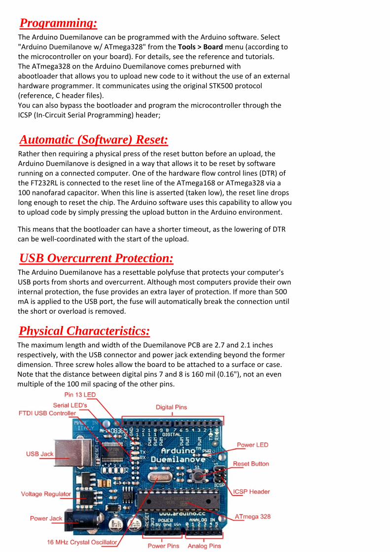
Physical Characteristics:
The maximum length and width of the Duemilanove PCB are 2.7 and 2.1 inches respectively, with the USB connector and power jack extending beyond the former dimension. Three screw holes allow the board to be attached to a surface or case. Note that the distance between digital pins 7 and 8 is 160 mil (0.16"), not an even multiple of the 100 mil spacing of the other pins.

Made in China