Embed Size (px)
Citation preview

ArDOT: A TOOL TO OPTIMISE ENVIRONMENTAL DESIGN OF BUILDINGS
Monjur Masum Mourshed, Denis Kelliher, and Marcus KeaneIRUSE (Informatics Research Unit for Sustainable Engineering)
Department of Civil & Environmental EngineeringNational University of Ireland Cork, Ireland
ABSTRACTEnvironmental design of buildings involves ‘finding the optimum’ solution satisfying predefinedobjective(s) (e.g., reduction in operating/capital cost, maximisation of daylighting etc.). A number ofcomputer based simulation models exist to assist professionals in finding this optimum throughbuilding performance assessment. Contemporarypractices involving building simulation requireenormous effort to prepare input, extract output, and visualize data, which restricts designers fromrealizing the full potentials offered. In most cases, rules of thumb are applied and experienced guesses are made; simulation software is used only tovalidate the assumptions, which do not necessarily lead to the intended optimum. Moreover, these toolshave been developed as simulation engines, which is inadequate to visualize the compounded andinterdependent effect of a large number of design variables.
The authors believe that to realize the potentialoffered by building simulation software, a new breed of DBSs (Decision Based Systems) is neededcoupling existing simulation engines with formaloptimisation methods through neutral data standards (BPM – building product models) for seamlessintegration. This paper first elaborates on theprevious attempts at solving integration issues related to the design process and simulation; also attempts at finding the limitations. Secondly, formulation ofdesign problems as optimisation has been discussed with reference to the different stages of design.Thirdly, for effective integration of activities among stakeholders and processes, the use of client/ server oriented building product model has been proposed to overcome the limitations of file-based prototypes. Analysis and discussions based on the above aspectsform as justification for ArDOT, an ArchitecturalDesign Optimisation Tool under development atIRUSE, National University of Ireland, Cork.Combining all three aspects into one makes ArDOT unique, which is essentially an enhanced decision making tool for the design of energy efficientbuildings.
INTRODUCTIONEnvironmental design in architecture requires anintegrated approach considering the domains ofthermal, visual, and acoustic, which have effects on human comfort. Current generation of simulationsoftware can be used to assess the environmental performance of the proposed building during design stages. They usually act on a single-view of the building as a system, be it thermal, visual, oracoustic. The use of such single-view tools for better and informed decision-making can be misleading.For example, increasing the glazing area in the south wall may increase the level of daylighting in interior spaces but leads to a significant increase in theheating/cooling load; thus requiring more energy tokeep the space within comfort range. Simulationsoftware, even the ‘integrated’ and ‘whole building’ ones are somewhat limited in modelling andrepresentation of multi-domain complexities. Given the focused nature of development activities inbuilding simulation community, some sort ofdecision-making tools are necessary combiningsingle-view programs into one.
The emphasis of the development activities inbuilding simulation has been to increase the domain-modelling capability. Little has been done tointegrate with the design process, for which they have been intended. Attempts made at developing the ‘design dashboard’ type of applications adding aseparate visualization front-end are not withoutlimitations (Mourshed et al. 2003). Such attempts at integration of simulation engines and visualization front-ends can be found in Papamichael et al. (1997), Hand (1998), and de Wilde et al. (2002). Thelimitations are mainly in the domain of visualization and decision-making. For example, to study thecombined effects of design variables in thedaylighting problem (e.g., how energy cost varies for different values of window area) described earlier, designer needs to simulate the building changing the window area gradually (parametric runs) andchecking the resultant daylighting level and heating/ cooling load. With the increase in the number( 2>n ) of design variables, )1( +n D design space (including the response) becomes hard tocomprehend and visualize. As most of the design
Eighth International IBPSA Conference Eindhoven, Netherlands
August 11-14, 2003
- 911 -- 919 -

problems are n-dimensional (where, 3>n ), authors argue that application of formal optimisationmethods is the only way to search design space effectively.
Success of any design integration efforts depends mostly on effective communication between actors and stakeholders. Building product models are the natural replacement of cumbersome, stand-alone, and proprietary representation of buildings. Althoughbuilding product models have been in existence for a number of years, their utilisation is still limited to the extraction of geometric information. Example can be found at Crawley et al. (2001) where IFC (Industrial Foundation Classes) have been used to convertgeometric information from IFC to IDF (EnergyPlus Input File) format. This file based Import-Exportactivity is unilateral (IFC to IDF only) and notwithout problems especially in mapping of objects. For effective integration adhering to the principles of building product models, two-way communication in a client/server environment is essential. Manipulation of design variables from within CAD systems (which adheres strictly to IFC principles) can lead to better environmental design of buildings.
Prior to describing ArDOT, key environmentaldesign activities with potential candidacy foroptimisation need to be identified. Design goals or objectives also need special considerations, as they are usually conflicting in engineering design domains (Anderson 2001). The aim is not to eliminateintuitiveness in the design process but to supplementwith analytical techniques, simulation software and optimisation methods. Previous attempts at design integration and optimisation in environmental design are described briefly followed by the considerations and the components that comprise ArDOT. The need for a single repository (building product model) to store building information is also established.
INTEGRATING SIMULATION IN DESIGNBuilding design is a sequential decision makingprocess where information flow is mostly horizontal at the beginning. This implies that brainstorming of specialists and stakeholders is not efficient at early stages. Moreover, ‘Composition of the design team, fragmentation of the process and activities make it unique from other mass-manufactured productdesign’ (Mourshed et al. 2003). These factorstogether with unstructured data inadequate for detail oriented computer programs slow the uptake ofsimulation in early design activities. Even inclusion of specialists at the earliest is not feasible except for a few exemplary and large projects.
Ongoing effortsDesign integration efforts can be classified into three depending on their approach. The first of thesefocuses on the interoperability issues, examples of which can found at Augenbroe (1995). Secondcategory can be termed as ‘process centric’ definition of interfaces with adequate provisions for human expertise and judgement (de Wilde 2002). Emphasis was placed on the workflow between ‘scenarios’,‘tasks’, and ‘users’. ‘Decision based’ is the last category, where decision making plays a pivotal role in driving design and simulation activities. BDA(Building Design Advisor) is an example, which is based on the theories of design (Papamichael et al. 1997). Other approaches are not distinct to becategorized differently (Extensions designed to ESPr, Semper etc.).
To allow non-specialists (e.g., architects) to usesimulation software a separate set of tools have been proposed and developed based on a simplifieddomain representation. In the course of time, they have been proved incapable to analyze thedownstream impacts of alternatives. They are also inadequate to handle the increasing array of available information as design progresses.
Apart from differences in approaches, all theintegration initiatives described above opted for a separate layer in the software architecture to deal with the decision-making aspect of design.Simulation engines are implemented and coupledmerely to generate responses. A review of ongoing initiatives by Augenbroe (2002) also suggests thesame. The authors argue that for successfulintegration, all three aspects need to be considered. Simply adopting ‘process-centric’ or ‘decision-centric’ approach or ‘enhancing interoperability’would not solve the problems. A closer look at the implementations (DAI- Design Analysis Integration, BDA, etc.) shows that they only allow analysis of a specific scenario of design. Too much emphasis on one particular aspect sacrificed the flexibility in the other.
On top of the three approaches, optimisation methodsneed to be implemented for effective decisionmaking in n-dimensional design spaces. Previous efforts on optimisation in environmental design are discussed later on in this paper, which shows that most implementations are AI (Artificial Intelligence) based, which are not the only types of algorithms. Experiments show that some of the gradient-basedalgorithms perform better in search of optimumenvironmental design.
- 912 -- 920 -

OutlineDesign
SchemeDesign
DetailedDesign
Feasibility& Site
Planning
Increasing complexity,Resolution of domain information
Architect
Building Services Engineer
LEGEND:
ENVIRONMENTAL DESIGN IN DIFFERENT STAGES Being unaware of formal optimisation methods, AEC (Architecture, Engineering, and Construction)professionals strive to achieve optimality in designs through minimizing or maximizing certainpredefined objectives. For each provisional design, the expected properties are predicted usingsimulation models, which are then compared to the requirements on the system. If the design does not meet the requirements, it is modified and evaluated again in the search for best possible design(Anderson 2001). The way to reach optimum ismostly experience based. Educated guesses are made to assume values of design variables and sometimes building simulation software is used to validate the expected performance. Moreover, the resolution of the domain knowledge increases as the designprogresses and degree of responsibility varies among professionals as in figure 1. During early stages,architects are mostly responsible. 20% of the design decisions taken at this stage taken subsequently influence 80% of all design decisions. Apart fromlarge-scale projects, energy consultants usually get involved at later and detailed stages, where most of the design decisions regarding building form, shape and elements are already made.
Figure 1: Degree of responsibilities of professionals with respect to environmental design in different
stages
It has been argued by researchers for the provision of some decision support tools at early stages to bridge the gap. Optimisation techniques, a branch ofdecision support systems can be of help in this regard. The kind of problems in environmentaldesign that can be solved using formal optimisation techniques are summarised in the following:
Feasibility & Site Planning:• Locating and approximate sizing of building,• Studies on form, shape, and reciprocal cost of
energy.
Outline Design:• Azimuth of the building (orientation with north),• Shape and form of the building,• Generic selection of materials based on
transmission co-efficient,• Architectural space programming and planning,• Schematic elevation (% glazing area),• Elementary appraisal of HVA C systems and fuel
type.
Scheme Design:• Detailed Elevation and Massing Studies,• Glazing area and type selection,• Choice of shading device on different facades,• Air change rate,• Daylighting and overall lighting design,• Selection of materials based on detailed analysis.
Detailed Design• Selection of heating/ cooling systems,• Heating/ cooling control strategies and
schedules,• Detailed HVAC design including ductwork,• Selection of ventilation strategies,• Minor adjustment to shape, form, elevation,
massing, materials.
OPTIMISATION IN ENVIRONMENTALDESIGNOptimisation activity in environmental design usually involves minimizing certain objectives (usually the Cost of Energy or Life Cycle Cost) and sometimes maximizing others (maximize Glazing Area) basedon user supplied constraints. Depending on thenumber objectives, it can be termed as single/multiple objective optimisations. A minimizationproblem can be mathematically formulated as:
Minimize )(xf (1.1)
Subject to ,0)( =xjhh
nj ,...2,1= (1.2)
,0)( <xk
g knk ,...2,1= (1.3)
,ui
xi
xli
x ≤≤ ,,...2,1 ni = (1.4)
Where, )(xf is the objective function;
nx xxxx ,...,,1= are design variables; hn is thenumber of equality constraints; kn is the number of inequality constraints; n is the number of design variables; l
ix and uix are lower and upper bounds on
a design variable, ix . (1.1) represents objectivefunction; (1.2) and (1.3) represents equality andinequality constraints respectively. (1.4) represents lower and upper bounds on design variables.
- 913 -- 921 -

Physical File Client/ Server SW Interface
EXPRESSIDL Definition
Application
Previous workApplications of optimisation techniques in thermal design of buildings include but not limited tooptimisation of building thermal envelope, HVACsystem, and control. Al-Homoud (1997) used direct search optimisation technique to optimize building envelope consisting of up to 14 variables using external simulation program. Caldas et al. (2002)used Genetic Algorithm coupled with DOE asresponse generator in optimal sizing of windows in a building for optimal heating, lighting and cooling performance. Nielsen (2002) prototyped anoptimisation system in Matlab using direct search simulated annealing algorithm to find the geometry and mix of building components that gives optimal performance. Other examples of optimisation ofbuilding envelope can be found at Marks (Marks 1997) and Bouchlaghem (Bouchlaghem 2000).
Applications in system optimisation can be found at Wright (Wright et al. 2002), in which multi-criteriongenetic algorithm has been used to investigate the pay-off between the HVAC system energy cost and occupant thermal discomfort; and at Gustafsson(Gustafsson 2000), in which Mixed Integer LinearProgramming (MILP) is used to retrofit building by optimising HVAC system and control strategies.
Apart from differences in objectives and algorithms used, these optimisation efforts can be categorized into two:
• Using hard-coded analytical equations of theunderlying principles of building thermal design (Marks 1997, Bouchlaghem 2000),
• Using black-box approach, in which externalsimulation programs are coupled withoptimisation algorithms to achieve a morerealistic solution to the problem (Caldas 2002, Nielsen 2002).
The latter offers more flexibility in the formulation of the problem and hence the solution which can also be used to solve problems of varying resolution. The objectives are like “black-box” functions, whichsupply output for a given input through simulation runs without the user needing to know the details of underlying technology. This approach also allows the use of matured and well-behaved building simulationmodels and lets user focus more on the optimisation then validating responses.
CONSIDERATIONSFor an optimisation tool to be incorporated in the design process, sharing and exchange of building information among various processes and software need to be seamless. Increasing dependency on computer-based tools during all life-cycle stages
from conception to recycling and reuse makes it more vital. Moreover, the proposed tool needs to have flexibility in the formulation of optimisation problem and the use of algorithm to fit in varied design scenario. This section describes two of the most important concepts behind the development of ArDOT.
Information modelling: Description of the buildingThe role of optimisation in environmental design of buildings is to help professionals take decisions to bridge the gap between design ideas and reality. It is thus necessary to extract and archive designinformation in a format that is understood by other stakeholders in the process. Deployment of building product models, theoretically addressing the semantic relationship among all elements, and containing data describing building is the only realistic way. IFC(Industrial Foundation Classes), a neutral AEC(Architecture, Engineering, and Construction) project model representing the AEC building lifecycleinformation, published by IAI (International Alliance for Interoperability) (Eastman 1999) has been chosen for implementation in this research. Figure 2 shows the three possible ways to share data using IFCs:
Figure 2: Ways of IFC implementation (after IAI 1999)
For (a) ease of design management, (b) elimination of data duplication, and (c) access to updatedbuilding information at any design stage, the client/ server method was implemented. Further IFCintegration into design software may allow direct SW (software) interface to be integrated in ArDOT.
- 914 -- 922 -
Optimisation AlgorithmEfficiency of any optimisation algorithm to converge to optimum depends on:
• the number and type of design variables,• the nature of the design space (linear, non-linear,
continuous, etc.).The optimisation problems in environmental design of buildings encountered by architects and building services engineer are usually multi-faceted. Thenumber of design variables is usually large and the true nature of solution space can not be known because of the blackbox approach in couplingsimulation software. The objective function may be linear or non-linear. Getting analytic derivatives from every simulation run to direct search process is not possible, rather they are obtained by finite difference methods. Therefore, it is necessary for a design optimisation tool to provide access to different types of algorithm to suit user needs. ArDOT facilitates the use of both gradient and non-gradient basedalgorithms through C API (Application Programming Interface) available in VisualDOC; a genericoptimization software developed by VR&D (Vrand 2002). Using commercial optimisation librariesreduces the tedious task of testing and benchmarking of algorithms needed for hard-coded implementation. Detailed description of all the algorithms used in ArDOT can be found in Vanderplaats (Vanderplaats 2001).
Figure 3: BFGS and Fletcher-Reeves steps (after VR&D 2002)
Gradient based optimisation
Both unconstrained and constrained minimization problems can be solved using gradient basedoptimisation algorithm. Figure 3 shows a gradient based minimization problem of design problem.Following gradient based methods are implemented in ArDOT:
• Unconstrained:o Broydon-Fletcher-Goldfarb-Shanno,o Fletcher-Reeves,o Sequential Unconstrained Optimisation.
• Constrained:o Sequential Quadratic Programming,o Sequential Linear Programming,o Modified Method of Feasible Directions,o Sequential Unconstrained Optimisation.
Design of Experiments
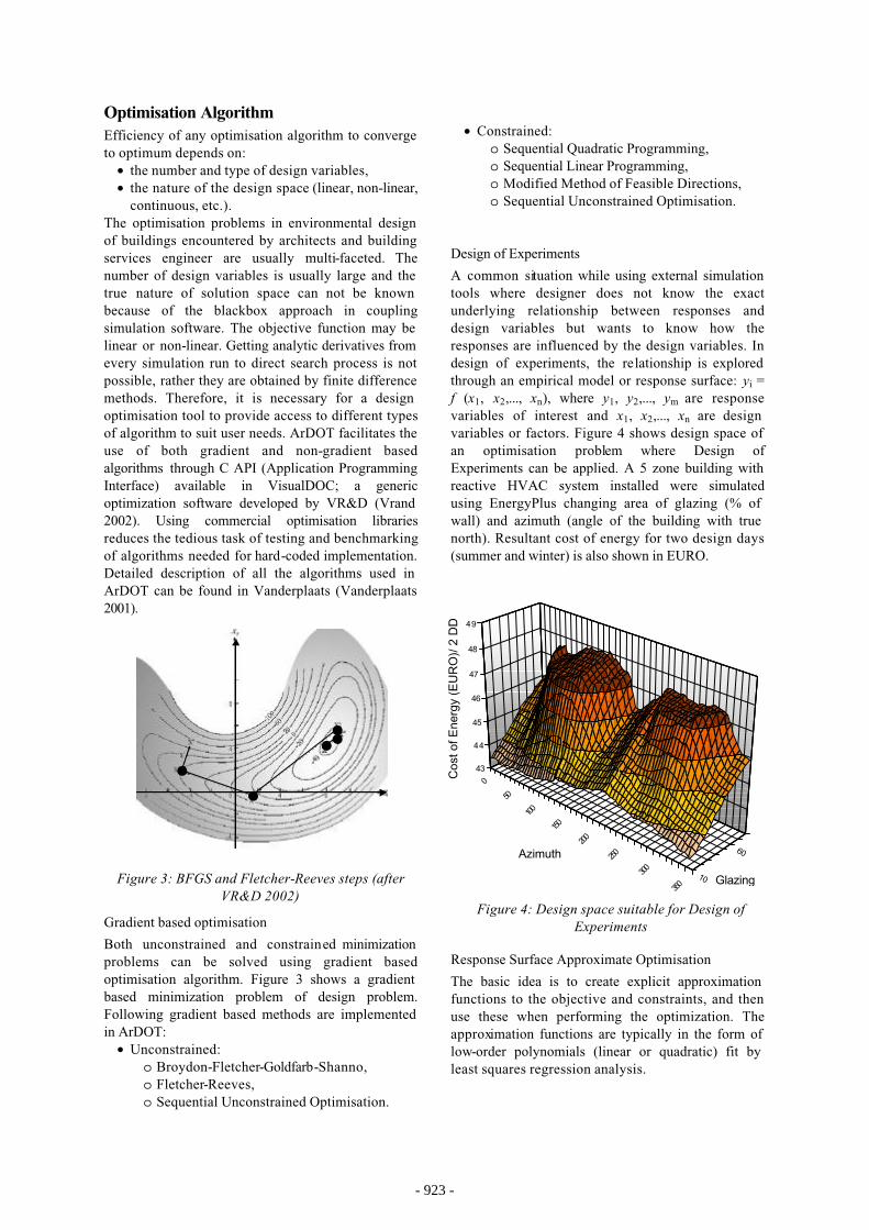
A common situation while using external simulation tools where designer does not know the exactunderlying relationship between responses anddesign variables but wants to know how theresponses are influenced by the design variables. In design of experiments, the relationship is explored through an empirical model or response surface: yi = f (x1, x2,..., xn), where y1, y2,..., ym are responsevariables of interest and x1, x2,..., xn are design variables or factors. Figure 4 shows design space of an optimisation problem where Design ofExperiments can be applied. A 5 zone building with reactive HVAC system installed were simulatedusing EnergyPlus changing area of glazing (% of wall) and azimuth (angle of the building with true north). Resultant cost of energy for two design days (summer and winter) is also shown in EURO.
Response Surface Approximate Optimisation
The basic idea is to create explicit approximation functions to the objective and constraints, and then use these when performing the optimization. Theapproximation functions are typically in the form of low-order polynomials (linear or quadratic) fit by least squares regression analysis.
Cos
t of E
nerg
y (E
UR
O)/
2 D
D
0
50
100
150
200
250
300
35010
60
43
44
45
46
47
48
49
Glazing
Azimuth
Figure 4: Design space suitable for Design of Experiments
- 915 -- 923 -

Non-Gradient based optimisation
Genetic Algorithm and Particle Swarm Algorithm are the two Non-Gradient Based Algorithms used in ArDOT. Genetic algorithm method is suitable forsolving problems where all the design variables are either integer or discrete, and the particle swarmmethod is suitable to deal with any mix ofcontinuous, discrete and integer design variables.
SYSTEM DEVELOPMENTFor flexibility and development, ArDOT has been designed in a modular fashion containing 3 main parts:
a. ArDOT Engineb. Response Generatorc. IFC Repository
ArDOT EngineOptimisation activity starts with the Buildinginformation obtained through querying the IFCModel Server and presented to the user in graphical format. The user then formulates optimisationproblem by choosing design variables, boundsassociated with them, constraints, and type ofoptimisation algorithm. I/O Processor inside ArDOTtransforms IFC data into inputs, handles calls to the
optimisation engine, makes necessary changes in the input, and calls appropriate response generator(s). Responses back from the response generator(simulation software) are processed and sent back tooptimisation algorithm to compute finite differences
and direct search process. Results from optimisation activity are refreshed and sent back to the IFCdatabase for archiving and design documentation. As most of the environmental design problems are multi-disciplinary and multi-objective, generating onesingle optimum may not be suitable to study pay-offcharacteristics. To facilitate pay-off study, a set of pareto optimal solutions can be produced as in figure 5, which shows possible pay-off curve betweenoperating cost and life-cycle cost, where every point in the curve is a design solution. These sorts of curves assists designer in situation where a trade-offneed to be made. For example, installing double-
Building Description
IFC BASED BUILDINGPRODUCT MODEL
IFCModel Server
RESPONSE GENERATOR
ASCII basedSimulationSoftware
EnergyPlus
ProblemFormulation
I/OProcessing
ResultVisualization
GBOGradient Based
Optimisation
RSOResponse Surface
Optimisation
DoEDesign of
Experiments
NGONon-Gradient
Based Optimisation
OPTIMISATION ENGINE
IFC→ ArDOTMapping
ArDOT → IFC Generator
Extract viewsArchitectural Design
Thermal Load CalculationsHVAC Design
Archive DesignFor Future Reference and Design Documentation
C++ / XML-HTTP C++ / XML-HTTP
Figure 6: Components of ArDOT
Operating Cost
Life
Cyc
le C
ost
Figure 5: Example pareto curve for pay-off study
- 916 -- 924 -

glazing in windows may reduce utility bill, but has a high associated capital/ life cycle cost. The curve shows that an increase in life-cycle cost reduces the operating cost, but up to a certain extent.
Response GeneratorAny simulation software handling ASCII based input and output files can be coupled with ArDOT. For test case implementation, the authors have coupledEngeryPlus, an integrated and whole-buildingsimulation software that builds on the strengths of previous initiatives BLAST and DOE-2 for accurate temperature and comfort prediction. Simulationcapabilities of EnergyPlus include integratedsimulation, combined heat and mass transfer balance, multi-zone airflow, HVAC loops (flexible systemand plant simulation), links to SPARK and TRNSYS system/plant simulation and algorithms from the newASHRAE loads toolkit (Crawley et al. 2001). Theunderlying building thermal zone calculation method in EnergyPlus is a heat balance model that gives a good understanding of interactions among different variables. The fundamental assumption of which is that air in each thermal zone can be modelled with uniform temperature throughout. The other majorassumption in heat balance models is that roomsurfaces (walls, windows, ceilings, and floors) have uniform surface temperatures, uniform long- andshort-wave irradiation, diffuse radiating surfaces, and one-dimensional heat conduction. However, foraccurate analysis, computational fluid dynamics(CFD) - a complex and computationally intensivesimulation of fluid (in this case, air) movement can be incorporated into ArDOT provided that thecomputing power needed for lengthy simulationsbecomes available and CFD tools become moresimple to use in the design development stages.
IFC RepositoryResearchers and professionals in the AEC industry have begun to realize the potentials Building Product Models offer. International initiatives geared towards setting up standards for data model in the industry has gained momentum. Major vendors have released versions of their software adhering to these standards (e.g. IFC). Among the three ways IFC can beimplemented “Client/ Server” method has beenchosen to facilitate (a) the use of updated design information at any particular time without the need to redefine data and (b) archival of the designsproduced during optimisation.
EDM (Express Data Manager), developed by EPM Technology has been chosen as IFC model server for implementation. EDM provides a framework forimplementing and connecting software applications
for sharing of industrial data in product’s design and operational life. It provides the necessary middleware to establish a shared database environment andinterfaces to Java and C/C++ without the need to install 3rd party DBMS (DataBase ManagementSystems) (EDM 2002). EDM complies with theinternational standards for “Industrial Automation systems and Integration - Product DataRepresentation and Exchange”; better known as ISO 10303 and STEP (STandard for Exchange of Product model data) (ISO 1994). IFC, based on the structure and framework of STEP and specified usingEXPRESS (ISO 1991); is also supported by EDM. IFC Entities and attributes are accessed through C++ API and processed in ArDOT for input preparation. After optimisation runs, resultant design iterations processed again and mapped to IFC for archival inthe IFC model server.
CONCLUSIONSThis paper describes ongoing efforts to integratesimulation tools in design and argues that simply focusing on the process, interoperability, or decision-making is not enough to solve the problems. Also discusses the limitations of graph based visualization and decision-making for n-dimensional designproblem. This establishes the need for formaloptimisation methods to search the design spaceeffectively. A brief discussion on previous attempts at optimisation activity in environmental reveals that too much emphasis has been put on the AI based techniques, which are not necessarily the mosteffective. Examples of which merely show thatoptimisation can be applied, but a coherent software environment is missing altogether that can be used in real life scenario.
This paper also presents ArDOT and its components and attempts to show the improvement that can be achieved by incorporating ‘process-centric’ ‘task-based’ ‘decision-making’ approach withinteroperability in mind. The unique feature is that ArDOT is flexible in problem definition,visualization, decision-making, and search of n-dimensional design spaces, which offers significant improvement over existing simulation engines orother interface-development initiatives. ArDOT not only facilitates optimisation by running analysis in a number of simulation engines but also allowsdesigners to analyze problems of varying domain resolution (e.g., from choosing the shape at thebeginning to selecting system properties at detailedstage). IFC is implemented on a ‘shared repository’ basis with added classes to facilitate design archival and reuse throughout all life-cycle stages, which is different from other file-based prototypes to transfer geometry.
- 917 -- 925 -

REFERENCESAl-Homoud, M. 1997. “Optimum Thermal Design of Air-Conditioned Residential Buildings”, Buildingand Environment, Vol. 32, No. 3, pp. 203-210.
Anderson, J. 2001. “Multiobjective Optimization in Engineering Design – Applications to Fluid Power Systems”, PhD Dissertation, Linköpings universitet, Sweden.
Augenbroe, G. 2002. “Trends in buildingsimulation”, Building and Environment, Vol. 37, No. 8-9, pp. 891-902.
Augenbroe, G. 1995. “COMBINE 2 Final Report”, Brussels, CEC Publication.
Bouchlaghem, N. 2000. “Optimising the design of building envelopes for thermal performance”,Automation in Construction, Vol. 10, No. 1, pp. 101-112.
Caldas, L.G., Norford, L.K. 2002. “A designoptimization tooll based on a genetic algorithm”Automation in Construction, Vol. 11, No. 2, pp 173-184.
Citherlet, S. 2001. “Towards the Holistic Assessment of Building Performance Based on an IntegratedSimulation Approach”, PhD dissertation, SwissFederal Institute of Technology, Lausanne,Switzerland.
Crawley, D.B., Lawrie, L.K., Winkelmann, F.C.,Buhl, W.F., Huang, Y.J., Pedersen, C.O., Strand,R.K., Liesen, R.J., Fisherm, D.E., Witte, M.J.,Glazer, J. 2001. “EnergyPlus: creating a new-generation building energy simulation program”,Energy and Buildings, Vol. 33, No. 4, pp. 319-331.
de Wilde, P., Augenbroe, G., der Voorden, M.V.2002. “Design analysis integration: supporting the selection of energy saving building components”,Buildings and Environment, Vol. 37, No. 8-9, pp. 807-816
EDM 2002. “EDM Assist Volume I: FundamentalConcepts”, EPM Technology, Oslo, Norway.
Eastman, C.M. 1999. “Building product models:computer environments supporting design andconstruction”, CRC Press, USA, pp 279-317.
Gustafsson, S. 2000. “Optimisation and simulation of building energy systems”, Applied ThermalEngineering, Vol. 20, No. XX, pp 1731-1741.
Hand, W.J. 1998. “Removing barriers to the use of simulation in the building design professions”, PhD Dissertation, University of Strathclyde, Glasgow,UK.
IAI 1999, “Introduction to IFC”, Webpage:http://cig.bre.co.uk/iai_uk/iai/page5.htm.
ISO 1991, “ISO DIS10303 Part11 - EXPRESSLanguage Reference Manual: ExternalRepresentation of Product Definition Data”, ISOTC184/SC4/WG5, Document N14, Switzerland.
ISO 1994, “ISO 10303-1:1994 Industrial automation systems and integration - Product data representation and exchange - Part 1: Overview and fundamental principles”, ISO, Switzerland.
Marks, W. 1997. “Multicriteria Optimisation ofShape of Energy-Saving Buildings”, Building and Environment, Vol. 32, No. 4, pp 331-339.
Mourshed, M.M., Kelliher, D., Keane, M. 2003.“Integrating building energy simulation in the design process”, IBPSA News, Vol. 13, No. 1, pp. 21-26.
Nielsen, T.R. 2002. “Optimisation of buildings with respect to energy and indoor environment”, PhDdissertation, Technical University of Denmark,Denmark.
Papamichael, K., LaPorta, J., Chauvet, H. 1997.“Building Design Advisor: Automated integration of multiple simulation tools”, Automation inConstruction, Vol. 6, No. 4, pp. 341-352.
Vanderplaats, G.N. 2001. “Numerical OptimizationTechniques for Engineering Design”, VR&D,Colorado Springs, USA.
VR&D 2002. “VisualDOC Design OptimizationSoftware Version 3.0 Theoretical Manual”, VR&D,Colorado Springs, USA.
Wright, J.A., Loosemore, H.A., Farmani, R. 2002.“Optimization of building thermal design and control by multi-criterion genetic algorithm”, Energy andBuildings, Vol. 34, No. XX, pp. 959-972.
- 918 -- 926 -