Embed Size (px)
Citation preview
FieldbusFBUS-HSE/H1 Linking Device (LD)User Manual
FBUS-HSE/H1 LD User Manual
May 2003 EditionPart Number 370728A-01
Support
Worldwide Technical Support and Product Information
ni.com
National Instruments Corporate Headquarters
11500 North Mopac Expressway Austin, Texas 78759-3504 USA Tel: 512 683 0100
Worldwide Offices
Australia 1800 300 800, Austria 43 0 662 45 79 90 0, Belgium 32 0 2 757 00 20, Brazil 55 11 3262 3599, Canada (Calgary) 403 274 9391, Canada (Montreal) 514 288 5722, Canada (Ottawa) 613 233 5949, Canada (Québec) 514 694 8521, Canada (Toronto) 905 785 0085, Canada (Vancouver) 514 685 7530, China 86 21 6555 7838, Czech Republic 420 2 2423 5774, Denmark 45 45 76 26 00, Finland 385 0 9 725 725 11, France 33 0 1 48 14 24 24, Germany 49 0 89 741 31 30, Greece 30 2 10 42 96 427, India 91 80 51190000, Israel 972 0 3 6393737, Italy 39 02 413091, Japan 81 3 5472 2970, Korea 82 02 3451 3400, Malaysia 603 9131 0918, Mexico 001 800 010 0793, Netherlands 31 0 348 433 466, New Zealand 1800 300 800, Norway 47 0 66 90 76 60, Poland 48 0 22 3390 150, Portugal 351 210 311 210, Russia 7 095 238 7139, Singapore 65 6226 5886, Slovenia 386 3 425 4200, South Africa 27 0 11 805 8197, Spain 34 91 640 0085, Sweden 46 0 8 587 895 00, Switzerland 41 56 200 51 51, Taiwan 886 2 2528 7227, Thailand 662 992 7519, United Kingdom 44 0 1635 523545
For further support information, refer to the Technical Support and Professional Services appendix. To comment on the documentation, send email to [email protected].
© 2003 National Instruments Corporation. All rights reserved.
Important Information
WarrantyThe FBUS-HSE/H1 Linking Device (LD) is warranted against defects in materials and workmanship for a period of one year from the date of shipment, as evidenced by receipts or other documentation. National Instruments will, at its option, repair or replace equipment that proves to be defective during the warranty period. This warranty includes parts and labor.
The media on which you receive National Instruments software are warranted not to fail to execute programming instructions, due to defects in materials and workmanship, for a period of 90 days from date of shipment, as evidenced by receipts or other documentation. National Instruments will, at its option, repair or replace software media that do not execute programming instructions if National Instruments receives notice of such defects during the warranty period. National Instruments does not warrant that the operation of the software shall be uninterrupted or error free.
A Return Material Authorization (RMA) number must be obtained from the factory and clearly marked on the outside of the package before any equipment will be accepted for warranty work. National Instruments will pay the shipping costs of returning to the owner parts which are covered by warranty.
National Instruments believes that the information in this document is accurate. The document has been carefully reviewed for technical accuracy. In the event that technical or typographical errors exist, National Instruments reserves the right to make changes to subsequent editions of this document without prior notice to holders of this edition. The reader should consult National Instruments if errors are suspected. In no event shall National Instruments be liable for any damages arising out of or related to this document or the information contained in it.
EXCEPT AS SPECIFIED HEREIN, NATIONAL INSTRUMENTS MAKES NO WARRANTIES, EXPRESS OR IMPLIED, AND SPECIFICALLY DISCLAIMS ANY WARRANTY OF MERCHANTABILITY OR FITNESS FOR A PARTICULAR PURPOSE. CUSTOMER’S RIGHT TO RECOVER DAMAGES CAUSED BY FAULT OR NEGLIGENCE ON THE PART OF NATIONAL INSTRUMENTS SHALL BE LIMITED TO THE AMOUNT THERETOFORE PAID BY THE CUSTOMER. NATIONAL INSTRUMENTS WILL NOT BE LIABLE FOR DAMAGES RESULTING FROM LOSS OF DATA, PROFITS, USE OF PRODUCTS, OR INCIDENTAL OR CONSEQUENTIAL DAMAGES, EVEN IF ADVISED OF THE POSSIBILITY THEREOF. This limitation of the liability of National Instruments will apply regardless of the form of action, whether in contract or tort, including negligence. Any action against National Instruments must be brought within one year after the cause of action accrues. National Instruments shall not be liable for any delay in performance due to causes beyond its reasonable control. The warranty provided herein does not cover damages, defects, malfunctions, or service failures caused by owner’s failure to follow the National Instruments installation, operation, or maintenance instructions; owner’s modification of the product; owner’s abuse, misuse, or negligent acts; and power failure or surges, fire, flood, accident, actions of third parties, or other events outside reasonable control.
CopyrightUnder the copyright laws, this publication may not be reproduced or transmitted in any form, electronic or mechanical, including photocopying, recording, storing in an information retrieval system, or translating, in whole or in part, without the prior written consent of National Instruments Corporation.
TrademarksFieldPoint™, HotPnP™, National Instruments™, NI™, NI-FBUS™, and ni.com™ are trademarks of National Instruments Corporation.
Product and company names mentioned herein are trademarks or trade names of their respective companies.
PatentsFor patents covering National Instruments products, refer to the appropriate location: Help»Patents in your software, the patents.txt file on your CD, or ni.com/patents.
WARNING REGARDING USE OF NATIONAL INSTRUMENTS PRODUCTS(1) NATIONAL INSTRUMENTS PRODUCTS ARE NOT DESIGNED WITH COMPONENTS AND TESTING FOR A LEVEL OF RELIABILITY SUITABLE FOR USE IN OR IN CONNECTION WITH SURGICAL IMPLANTS OR AS CRITICAL COMPONENTS IN ANY LIFE SUPPORT SYSTEMS WHOSE FAILURE TO PERFORM CAN REASONABLY BE EXPECTED TO CAUSE SIGNIFICANT INJURY TO A HUMAN.
(2) IN ANY APPLICATION, INCLUDING THE ABOVE, RELIABILITY OF OPERATION OF THE SOFTWARE PRODUCTS CAN BE IMPAIRED BY ADVERSE FACTORS, INCLUDING BUT NOT LIMITED TO FLUCTUATIONS IN ELECTRICAL POWER SUPPLY, COMPUTER HARDWARE MALFUNCTIONS, COMPUTER OPERATING SYSTEM SOFTWARE FITNESS, FITNESS OF COMPILERS AND DEVELOPMENT SOFTWARE USED TO DEVELOP AN APPLICATION, INSTALLATION ERRORS, SOFTWARE AND HARDWARE COMPATIBILITY PROBLEMS, MALFUNCTIONS OR FAILURES OF ELECTRONIC MONITORING OR CONTROL DEVICES, TRANSIENT FAILURES OF ELECTRONIC SYSTEMS (HARDWARE AND/OR SOFTWARE), UNANTICIPATED USES OR MISUSES, OR ERRORS ON THE PART OF THE USER OR APPLICATIONS DESIGNER (ADVERSE FACTORS SUCH AS THESE ARE HEREAFTER COLLECTIVELY TERMED “SYSTEM FAILURES”). ANY APPLICATION WHERE A SYSTEM FAILURE WOULD CREATE A RISK OF HARM TO PROPERTY OR PERSONS (INCLUDING THE RISK OF BODILY INJURY AND DEATH) SHOULD NOT BE RELIANT SOLELY UPON ONE FORM OF ELECTRONIC SYSTEM DUE TO THE RISK OF SYSTEM FAILURE. TO AVOID DAMAGE, INJURY, OR DEATH, THE USER OR APPLICATION DESIGNER MUST TAKE REASONABLY PRUDENT STEPS TO PROTECT AGAINST SYSTEM FAILURES, INCLUDING BUT NOT LIMITED TO BACK-UP OR SHUT DOWN MECHANISMS. BECAUSE EACH END-USER SYSTEM IS CUSTOMIZED AND DIFFERS FROM NATIONAL INSTRUMENTS' TESTING PLATFORMS AND BECAUSE A USER OR APPLICATION DESIGNER MAY USE NATIONAL INSTRUMENTS PRODUCTS IN COMBINATION WITH OTHER PRODUCTS IN A MANNER NOT EVALUATED OR CONTEMPLATED BY NATIONAL INSTRUMENTS, THE USER OR APPLICATION DESIGNER IS ULTIMATELY RESPONSIBLE FOR VERIFYING AND VALIDATING THE SUITABILITY OF NATIONAL INSTRUMENTS PRODUCTS WHENEVER NATIONAL INSTRUMENTS PRODUCTS ARE INCORPORATED IN A SYSTEM OR APPLICATION, INCLUDING, WITHOUT LIMITATION, THE APPROPRIATE DESIGN, PROCESS AND SAFETY LEVEL OF SUCH SYSTEM OR APPLICATION.
Compliance
FCC/Canada Radio Frequency Interference Compliance
Determining FCC ClassThe Federal Communications Commission (FCC) has rules to protect wireless communications from interference. The FCC places digital electronics into two classes. These classes are known as Class A (for use in industrial-commercial locations only) or Class B (for use in residential or commercial locations). All National Instruments (NI) products are FCC Class A products.Depending on where it is operated, this Class A product could be subject to restrictions in the FCC rules. (In Canada, the Department of Communications (DOC), of Industry Canada, regulates wireless interference in much the same way.) Digital electronics emit weak signals during normal operation that can affect radio, television, or other wireless products.All Class A products display a simple warning statement of one paragraph in length regarding interference and undesired operation. The FCC rules have restrictions regarding the locations where FCC Class A products can be operated.Consult the FCC Web site at www.fcc.gov for more information.
FCC/DOC WarningsThis equipment generates and uses radio frequency energy and, if not installed and used in strict accordance with the instructions in this manual and the CE marking Declaration of Conformity*, may cause interference to radio and television reception. Classification requirements are the same for the Federal Communications Commission (FCC) and the Canadian Department of Communications (DOC). Changes or modifications not expressly approved by NI could void the user’s authority to operate the equipment under the FCC Rules.
Class AFederal Communications CommissionThis equipment has been tested and found to comply with the limits for a Class A digital device, pursuant to part 15 of the FCC Rules. These limits are designed to provide reasonable protection against harmful interference when the equipment is operated in a commercial environment. This equipment generates, uses, and can radiate radio frequency energy and, if not installed and used in accordance with the instruction manual, may cause harmful interference to radio communications. Operation of this equipment in a residential area is likely to cause harmful interference in which case the user is required to correct the interference at their own expense.
Canadian Department of CommunicationsThis Class A digital apparatus meets all requirements of the Canadian Interference-Causing Equipment Regulations.Cet appareil numérique de la classe A respecte toutes les exigences du Règlement sur le matériel brouilleur du Canada.
Compliance to EU DirectivesReaders in the European Union (EU) must refer to the manufacturer’s Declaration of Conformity (DoC) for information* pertaining to the CE marking compliance scheme. The manufacturer includes a DoC for most hardware products except for those bought from OEMs. In addition, DoCs are usually not provided if compliance is not required, for example electrically benign apparatus or cables.To obtain the DoC for this product, click Declarations of Conformity Information at ni.com/hardref.nsf/. This Web site lists the DoCs by product family. Select the appropriate product family, followed by your product, and a link to the DoC appears in Adobe Acrobat format. Click the Acrobat icon to download or read the DoC.
* The CE marking Declaration of Conformity contains important supplementary information and instructions for the user or installer.
© National Instruments Corporation v FBUS-HSE/H1 LD User Manual
Contents
About This ManualHow To Use the Manual Set..........................................................................................viiConventions ...................................................................................................................viiRelated Documentation..................................................................................................viii
Chapter 1Overview of FBUS-HSE/H1 Linking Device (LD) Hardware
Product Overview ..........................................................................................................1-1Configuration and Monitoring.........................................................................1-2System Requirements ......................................................................................1-3
Hardware...........................................................................................1-3Software ............................................................................................1-3Compatibility Information ................................................................1-3
FBUS-HSE/H1 LD Hardware Description .....................................................1-3
Chapter 2Hardware Installation and Configuration
Installing the FBUS-HSE/H1 LD ..................................................................................2-1Removing the FBUS-HSE/H1 LD ..................................................................2-2Mounting the FBUS-HSE/H1 LD to a Panel ..................................................2-2
Connect Your FBUS-HSE/H1 LD to the Network........................................................2-3Cabling...........................................................................................................................2-4Connect the FBUS-HSE/H1 LD to the Fieldbus Network ............................................2-5Connect Power to the FBUS-HSE/H1 LD.....................................................................2-6Power on the FBUS-HSE/H1 LD ..................................................................................2-7
Appendix AResetting the FBUS-HSE/H1 LD
Appendix BTroubleshooting
Appendix CSpecifications
Contents
FBUS-HSE/H1 LD User Manual vi ni.com
Appendix DTechnical Support and Professional Services
Glossary
Index
© National Instruments Corporation vii FBUS-HSE/H1 LD User Manual
About This Manual
This manual describes the mechanical and electrical aspects of the FBUS-HSE/H1 Linking Device (LD) and contains information concerning its installation and operation. The FBUS-HSE/H1 LD product is a High Speed Ethernet to Foundation H1 Linking Device.
How To Use the Manual SetBegin by reading the Getting Started with Your FBUS-HSE/H1 Linking Device manual, a brief quick-start manual that describes how to set up and get started with your kit using the default settings.
This manual contains more details about changing the installation or configuration from the defaults, and about using the hardware.
ConventionsThis manual uses the following conventions:
» The » symbol leads you through nested menu items and dialog box options to a final action. The sequence File»Page Setup»Options directs you to pull down the File menu, select the Page Setup item, and select Options from the last dialog box.
This icon denotes a note, which alerts you to important information.
This icon denotes a caution, which advises you of precautions to take to avoid injury, data loss, or a system crash.
bold Bold text denotes items that you must select or click in the software, such as menu items and dialog box options. Bold text also denotes parameter names.
italic Italic text denotes variables, emphasis, a cross reference, or an introduction to a key concept. This font also denotes text that is a placeholder for a word or value that you must supply.
monospace Text in this font denotes text or characters that you should enter from the keyboard, sections of code, programming examples, and syntax examples. This font is also used for the proper names of disk drives, paths, directories,
About This Manual
FBUS-HSE/H1 LD User Manual viii ni.com
programs, subprograms, subroutines, device names, functions, operations, variables, filenames and extensions, and code excerpts.
Related DocumentationThe following documents contain information you might find helpful as you read this manual:
• Foundation Fieldbus Specification: System Architecture
• NI-FBUS Configurator User Manual
• Getting Started with Your HSE Linking Device and the NI-FBUS Software
© National Instruments Corporation 1-1 FBUS-HSE/H1 LD User Manual
1Overview of FBUS-HSE/H1 Linking Device (LD) Hardware
This chapter provides an overview of the FBUS-HSE/H1 Linking Device (LD) hardware.
Product OverviewHigh Speed Ethernet (HSE) is an extension to the Foundation Fieldbus specification and is governed by the Foundation Fieldbus organization. HSE compliments the Foundation Fieldbus H1 network (31.25 kb/s) specification by offering a high speed (10 Mb/s) link to H1 segments. Built on standard Ethernet, HSE extrapolates the Fieldbus protocol and offers controllers the ability to schedule and control H1 devices directly over Ethernet.
An FBUS-HSE/H1 system consists of at least one linking device connected to an Ethernet network and at least one H1 device.
The FBUS-HSE/H1 LD connects a 10 Mbps Ethernet network to Fieldbus H1 devices. Each H1 network can be connected to multiple Fieldbus devices. Each FBUS-HSE/H1 can support two H1 segments, and each segment can support up to 16 H1 field devices (without repeaters). Because the FBUS-HSE/H1 LD is an HSE linking device, your network topology determines the maximum number of FBUS-HSE/H1 LDs that can be installed on your Ethernet network.
The FBUS-HSE/H1 LD connects directly to a 10 Mbps Ethernet network. The FBUS-HSE/H1 autodetects the speed of the Ethernet connection and configures itself accordingly.
Chapter 1 Overview of FBUS-HSE/H1 Linking Device (LD) Hardware
FBUS-HSE/H1 LD User Manual 1-2 ni.com
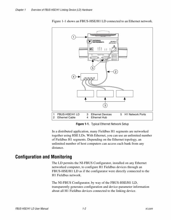
Figure 1-1 shows an FBUS-HSE/H1 LD connected to an Ethernet network.
Figure 1-1. Typical Ethernet Network Setup
In a distributed application, many Fieldbus H1 segments are networked together using HSE LDs. With Ethernet, you can use an unlimited number of Fieldbus H1 segments. Depending on the Ethernet topology, an unlimited number of host computers can access each bank from any distance.
Configuration and MonitoringThe LD permits the NI-FBUS Configurator, installed on any Ethernet networked computer, to configure H1 Fieldbus devices through an FBUS-HSE/H1 LD as if the configurator were directly connected to the H1 Fieldbus network.
The NI-FBUS Configurator, by way of the FBUS-HSE/H1 LD, transparently generates configuration and device-parameter information about all H1 Fieldbus devices connected to the linking device.
1 FBUS-HSE/H1 LD2 Ethernet Cable
3 Ethernet Devices4 Ethernet Hub
5 H1 Network Ports
1
2
4
3
5
Chapter 1 Overview of FBUS-HSE/H1 Linking Device (LD) Hardware
© National Instruments Corporation 1-3 FBUS-HSE/H1 LD User Manual
Once configured, the linking device permits HMI software on any PC connected to an FBUS-HSE/H1 LD to access and monitor Fieldbus devices as if the HMI were directly connected to the Fieldbus network.
System RequirementsThis section describes the hardware and software components you need before you can use the linking device. You also should review the README.TXT file on the linking device setup disk for the latest information.
Hardware• FBUS-HSE/H1 LD
• Ethernet 10/100 Mbps network interface
• Ethernet network cabling
• Fieldbus cabling
Software• Windows NT 4.0 with service pack 3 or later, or Windows 2000/XP
• NI-FBUS Configurator version 3.0 or later
• DHCP Server
Compatibility InformationThe linking device is compatible with IEEE 802.3, the Fieldbus Foundation specification, and the Fieldbus Foundation HSE specification.
FBUS-HSE/H1 LD Hardware DescriptionThe linking device is designed to be mounted on a 35 mm DIN rail and has one Ethernet port. The Ethernet status LEDs on the front of the linking device display the current status of Ethernet link.
The linking device has two separate H1 Fieldbus ports. Next to each port is an LED to display the current port status.
The STATUS LED indicates whether the linking device is powered on and operating properly.
For more information on connecting and configuring the linking device, refer to Chapter 2, Hardware Installation and Configuration.
© National Instruments Corporation 2-1 FBUS-HSE/H1 LD User Manual
2Hardware Installation and Configuration
Installing the FBUS-HSE/H1 LDThe FBUS-HSE/H1 LD has a simple rail clip for reliable mounting onto a standard 35 mm DIN rail. Complete the following steps to mount the FBUS-HSE/H1 LD on a DIN rail.
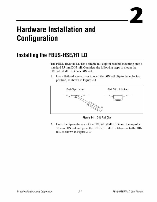
1. Use a flathead screwdriver to open the DIN rail clip to the unlocked position, as shown in Figure 2-1.
Figure 2-1. DIN Rail Clip
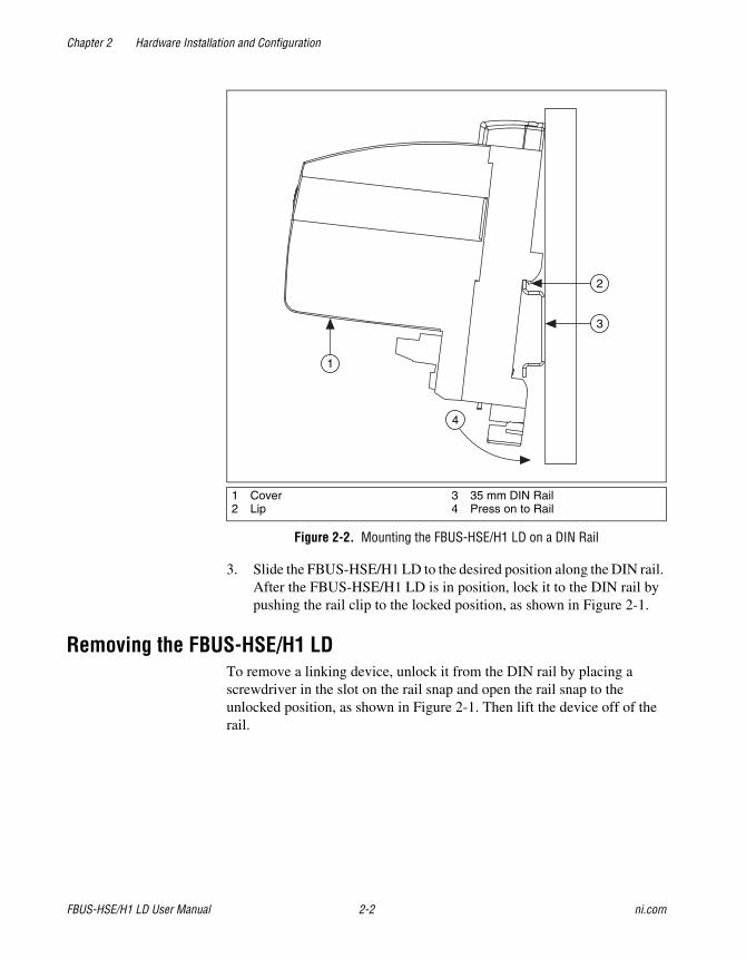
2. Hook the lip on the rear of the FBUS-HSE/H1 LD onto the top of a 35 mm DIN rail and press the FBUS-HSE/H1 LD down onto the DIN rail, as shown in Figure 2-2.
Rail Clip Locked Rail Clip Unlocked
Chapter 2 Hardware Installation and Configuration
FBUS-HSE/H1 LD User Manual 2-2 ni.com
Figure 2-2. Mounting the FBUS-HSE/H1 LD on a DIN Rail
3. Slide the FBUS-HSE/H1 LD to the desired position along the DIN rail. After the FBUS-HSE/H1 LD is in position, lock it to the DIN rail by pushing the rail clip to the locked position, as shown in Figure 2-1.
Removing the FBUS-HSE/H1 LDTo remove a linking device, unlock it from the DIN rail by placing a screwdriver in the slot on the rail snap and open the rail snap to the unlocked position, as shown in Figure 2-1. Then lift the device off of the rail.
1 Cover2 Lip
3 35 mm DIN Rail4 Press on to Rail
4
1
2
3

Chapter 2 Hardware Installation and Configuration
© National Instruments Corporation 2-3 FBUS-HSE/H1 LD User Manual
Mounting the FBUS-HSE/H1 LD to a PanelComplete the following steps to install the optional Fieldbus network panel mount accessory and mount the FBUS-HSE/H1 LD network module to a panel. You can order the panel mount accessory from National Instruments.
1. Use a flathead screwdriver to open the rail clip to the unlocked position, as shown in Figure 2-1.
2. Snap the panel mount accessory onto the module, as shown in Figure 2-3.
Figure 2-3. Installing the Network Panel Mount Accessory
3. Lock the panel mount accessory into place by pushing the rail clip to the locked position.
4. Mount the FBUS-HSE/H1 LD to your panel with the panel mount accessory.
Chapter 2 Hardware Installation and Configuration
FBUS-HSE/H1 LD User Manual 2-4 ni.com
Connect Your FBUS-HSE/H1 LD to the NetworkConnect the RJ-45 Ethernet port of the FBUS-HSE/H1 LD to an Ethernet hub using a standard Category 5 Ethernet cable. You also can connect an FBUS-HSE/H1 LD directly to a computer using an Ethernet crossover cable.
Note Do not use a cable longer than 100 m. If you are using a 10 Mbps Ethernet, National Instruments recommends using a Category 5 shielded twisted-pair Ethernet cable.
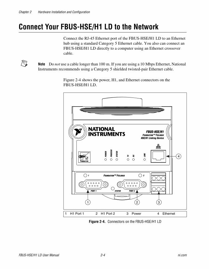
Figure 2-4 shows the power, H1, and Ethernet connectors on the FBUS-HSE/H1 LD.
Figure 2-4. Connectors on the FBUS-HSE/H1 LD
1 H1 Port 1 2 H1 Port 2 3 Power 4 Ethernet
1 2 3
4
Chapter 2 Hardware Installation and Configuration
© National Instruments Corporation 2-5 FBUS-HSE/H1 LD User Manual
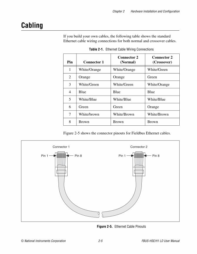
CablingIf you build your own cables, the following table shows the standard Ethernet cable wiring connections for both normal and crossover cables.
Figure 2-5 shows the connector pinouts for Fieldbus Ethernet cables.
Figure 2-5. Ethernet Cable Pinouts
Table 2-1. Ethernet Cable Wiring Connections
Pin Connector 1Connector 2
(Normal)Connector 2(Crossover)
1 White/Orange White/Orange White/Green
2 Orange Orange Green
3 White/Green White/Green White/Orange
4 Blue Blue Blue
5 White/Blue White/Blue White/Blue
6 Green Green Orange
7 White/brown White/Brown White/Brown
8 Brown Brown Brown
Connector 1 Connector 2
Pin 1 Pin 1 Pin 8Pin 8
Chapter 2 Hardware Installation and Configuration
FBUS-HSE/H1 LD User Manual 2-6 ni.com
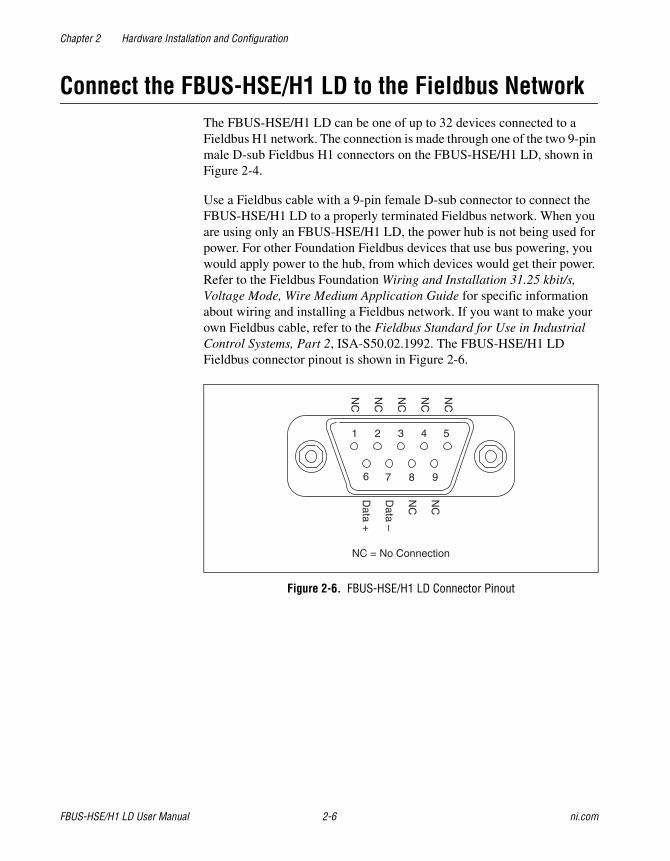
Connect the FBUS-HSE/H1 LD to the Fieldbus NetworkThe FBUS-HSE/H1 LD can be one of up to 32 devices connected to a Fieldbus H1 network. The connection is made through one of the two 9-pin male D-sub Fieldbus H1 connectors on the FBUS-HSE/H1 LD, shown in Figure 2-4.
Use a Fieldbus cable with a 9-pin female D-sub connector to connect the FBUS-HSE/H1 LD to a properly terminated Fieldbus network. When you are using only an FBUS-HSE/H1 LD, the power hub is not being used for power. For other Foundation Fieldbus devices that use bus powering, you would apply power to the hub, from which devices would get their power. Refer to the Fieldbus Foundation Wiring and Installation 31.25 kbit/s, Voltage Mode, Wire Medium Application Guide for specific information about wiring and installing a Fieldbus network. If you want to make your own Fieldbus cable, refer to the Fieldbus Standard for Use in Industrial Control Systems, Part 2, ISA-S50.02.1992. The FBUS-HSE/H1 LD Fieldbus connector pinout is shown in Figure 2-6.
Figure 2-6. FBUS-HSE/H1 LD Connector Pinout
1 2 3 4 5
6 7 8 9
NC
NC
NC
NC
NC
NC
NC
Data +
Data –
NC = No Connection
Chapter 2 Hardware Installation and Configuration
© National Instruments Corporation 2-7 FBUS-HSE/H1 LD User Manual
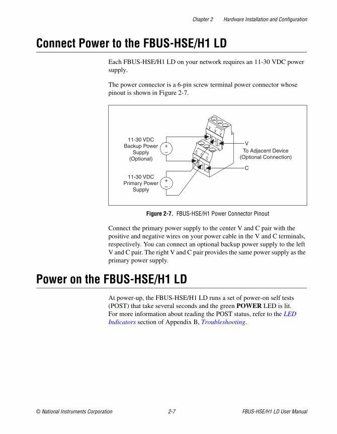
Connect Power to the FBUS-HSE/H1 LDEach FBUS-HSE/H1 LD on your network requires an 11-30 VDC power supply.
The power connector is a 6-pin screw terminal power connector whose pinout is shown in Figure 2-7.
Figure 2-7. FBUS-HSE/H1 Power Connector Pinout
Connect the primary power supply to the center V and C pair with the positive and negative wires on your power cable in the V and C terminals, respectively. You can connect an optional backup power supply to the left V and C pair. The right V and C pair provides the same power supply as the primary power supply.
Power on the FBUS-HSE/H1 LDAt power-up, the FBUS-HSE/H1 LD runs a set of power-on self tests (POST) that take several seconds and the green POWER LED is lit. For more information about reading the POST status, refer to the LED Indicators section of Appendix B, Troubleshooting.
vv v
c cc
11-30 VDCBackup Power
Supply(Optional)
+–
+–
11-30 VDCPrimary Power
Supply
V
C
To Adjacent Device(Optional Connection)
© National Instruments Corporation A-1 FBUS-HSE/H1 LD User Manual
AResetting the FBUS-HSE/H1 LD
If the FBUS-HSE/H1 LD cannot communicate with the network, you can configure the Ethernet settings through NI-FBUS software. When you configure the device, it attempts to confirm that the new settings are valid. However, if the configuration process is interrupted or the FBUS-HSE/H1 LD is moved to a new network with different settings, the device might not be able to communicate with the network. If this occurs, you can manually reset the unit to its factory settings.
Complete the follow steps to reset the unit.
1. Power down the FBUS-HSE/H1 LD and remove it from the bank.
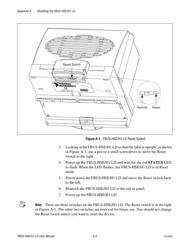
2. Locate the slot on the bottom of the FBUS-HSE/H1 LD just above the label. Inside the slot, find the red reset switch, shown in Figure A-1.
Appendix A Resetting the FBUS-HSE/H1 LD
FBUS-HSE/H1 LD User Manual A-2 ni.com
Figure A-1. FBUS-HSE/H1 LD Reset Switch
3. Looking at the FBUS-HSE/H1 LD so that the label is upright, as shown in Figure A-1, use a pen or a small screwdriver to move the Reset switch to the right.
4. Power up the FBUS-HSE/H1 LD and wait for the red STATUS LED to flash. When the LED flashes, the FBUS-HSE/H1 LD is in Reset mode.
5. Power down the FBUS-HSE/H1 LD and move the Reset switch back to the left.
6. Reattach the FBUS-HSE/H1 LD to the rail or panel.
7. Power up the FBUS-HSE/H1 LD.
Note There are three switches on the FBUS-HSE/H1 LD. The Reset switch is at the right in Figure A-1. The other two switches are reserved for future use. You should not change the Reset Switch unless you want to reset the device.
Made in the USA
Reset Switch
Normal Reset
© National Instruments Corporation B-1 FBUS-HSE/H1 LD User Manual
BTroubleshooting
LED Indicators
HardwareThe FBUS-HSE/H1 LD has seven LED indicators on the top panel and three LEDs on the front panel, as shown in Figure B-1.
Appendix B Troubleshooting
FBUS-HSE/H1 LD User Manual B-2 ni.com
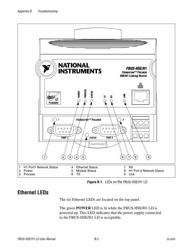
Figure B-1. LEDs on the FBUS-HSE/H1 LD
Ethernet LEDsThe six Ethernet LEDs are located on the top panel.
The green POWER LED is lit while the FBUS-HSE/H1 LD is powered up. This LED indicates that the power supply connected to the FBUS-HSE/H1 LD is acceptable.
1 H1 Port1 Network Status2 Power3 Process
4 Ethernet Status5 Module Status6 TX
7 RX8 H1 Port 2 Network Status9 Link
2 43 761 95 8
Appendix B Troubleshooting
© National Instruments Corporation B-3 FBUS-HSE/H1 LD User Manual
Caution Do not power down the FBUS-HSE/H1 LD while the PROCESS LED is lit.
The green PROCESS LED is lit when you update the nonvolatile flash memory of the FBUS-HSE/H1 LD. If you want to change network settings, save channel settings or power-up values, or upgrade its firmware, you need to update the nonvolatile flash memory.
The red Ethernet STATUS LED is lit when the FBUS-HSE/H1 LD detects an error. The FBUS-HSE/H1 LD indicates specific error conditions by flashing STATUS LED a specific number of times. Table B-1 describes the STATUS LED flashing sequences and the corresponding error conditions.
The green TX LED is lit when the FBUS-HSE/H1 LD transmits data over the Ethernet.
The green RX LED is lit when the FBUS-HSE/H1 LD receives data from the Ethernet. Because of unrelated network traffic, this LED blinks occasionally even when the FBUS-HSE/H1 LD is inactive.
The green LINK LED is lit when the FBUS-HSE/H1 LD is connected to an active Ethernet segment.
Appendix B Troubleshooting
FBUS-HSE/H1 LD User Manual B-4 ni.com
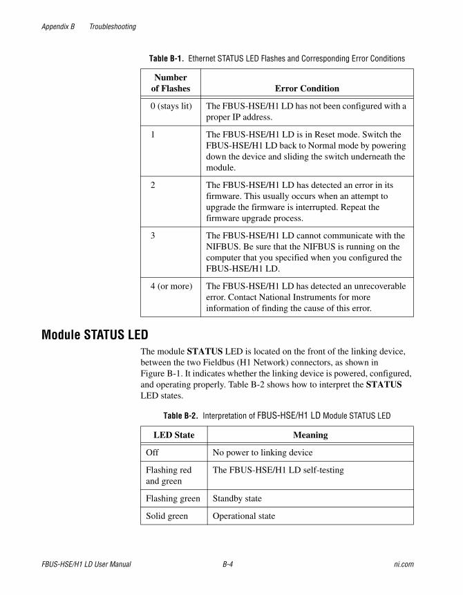
Module STATUS LEDThe module STATUS LED is located on the front of the linking device, between the two Fieldbus (H1 Network) connectors, as shown in Figure B-1. It indicates whether the linking device is powered, configured, and operating properly. Table B-2 shows how to interpret the STATUS LED states.
Table B-1. Ethernet STATUS LED Flashes and Corresponding Error Conditions
Number of Flashes Error Condition
0 (stays lit) The FBUS-HSE/H1 LD has not been configured with a proper IP address.
1 The FBUS-HSE/H1 LD is in Reset mode. Switch the FBUS-HSE/H1 LD back to Normal mode by powering down the device and sliding the switch underneath the module.
2 The FBUS-HSE/H1 LD has detected an error in its firmware. This usually occurs when an attempt to upgrade the firmware is interrupted. Repeat the firmware upgrade process.
3 The FBUS-HSE/H1 LD cannot communicate with the NIFBUS. Be sure that the NIFBUS is running on the computer that you specified when you configured the FBUS-HSE/H1 LD.
4 (or more) The FBUS-HSE/H1 LD has detected an unrecoverable error. Contact National Instruments for more information of finding the cause of this error.
Table B-2. Interpretation of FBUS-HSE/H1 LD Module STATUS LED
LED State Meaning
Off No power to linking device
Flashing red and green
The FBUS-HSE/H1 LD self-testing
Flashing green Standby state
Solid green Operational state
Appendix B Troubleshooting
© National Instruments Corporation B-5 FBUS-HSE/H1 LD User Manual
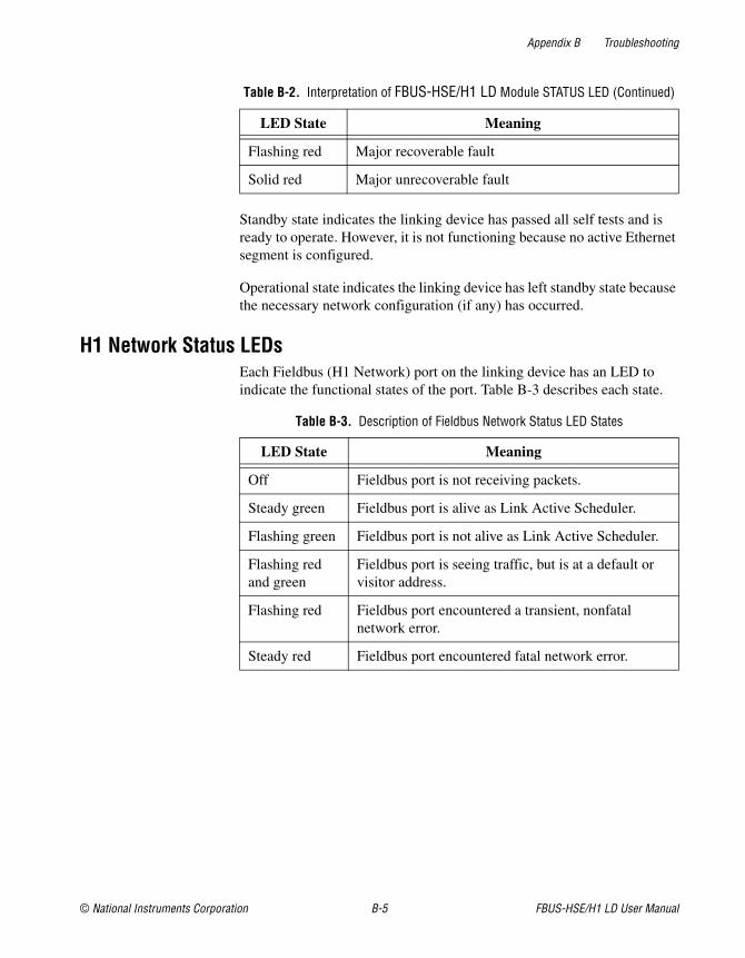
Standby state indicates the linking device has passed all self tests and is ready to operate. However, it is not functioning because no active Ethernet segment is configured.
Operational state indicates the linking device has left standby state because the necessary network configuration (if any) has occurred.
H1 Network Status LEDsEach Fieldbus (H1 Network) port on the linking device has an LED to indicate the functional states of the port. Table B-3 describes each state.
Flashing red Major recoverable fault
Solid red Major unrecoverable fault
Table B-3. Description of Fieldbus Network Status LED States
LED State Meaning
Off Fieldbus port is not receiving packets.
Steady green Fieldbus port is alive as Link Active Scheduler.
Flashing green Fieldbus port is not alive as Link Active Scheduler.
Flashing red and green
Fieldbus port is seeing traffic, but is at a default or visitor address.
Flashing red Fieldbus port encountered a transient, nonfatal network error.
Steady red Fieldbus port encountered fatal network error.
Table B-2. Interpretation of FBUS-HSE/H1 LD Module STATUS LED (Continued)
LED State Meaning
© National Instruments Corporation C-1 FBUS-HSE/H1 LD User Manual
CSpecifications
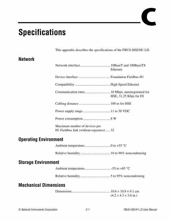
This appendix describes the specifications of the FBUS-HSE/H1 LD.
NetworkNetwork interface................................... 10BaseT and 100BaseTX
Ethernet
Device interface ..................................... Foundation Fieldbus H1
Compatibility ......................................... High Speed Ethernet
Communication rates ............................. 10 Mbps, autonegotiated for HSE, 31.25 Kbps for H1
Cabling distance..................................... 100 m for HSE
Power supply range................................ 11 to 30 VDC
Power consumption................................ 8 W
Maximum number of devices per H1 Fieldbus link (without repeaters) ..... 32
Operating EnvironmentAmbient temperature.............................. 0 to +55 °C
Relative humidity ................................... 10 to 90% noncondensing
Storage EnvironmentAmbient temperature.............................. –55 to +85 °C
Relative humidity ................................... 5 to 95% noncondensing
Mechanical DimensionsDimensions............................................. 10.6 × 10.9 × 9.1 cm
(4.2 × 4.3 × 3.6 in.)
Appendix C Specifications
FBUS-HSE/H1 LD User Manual C-2 ni.com
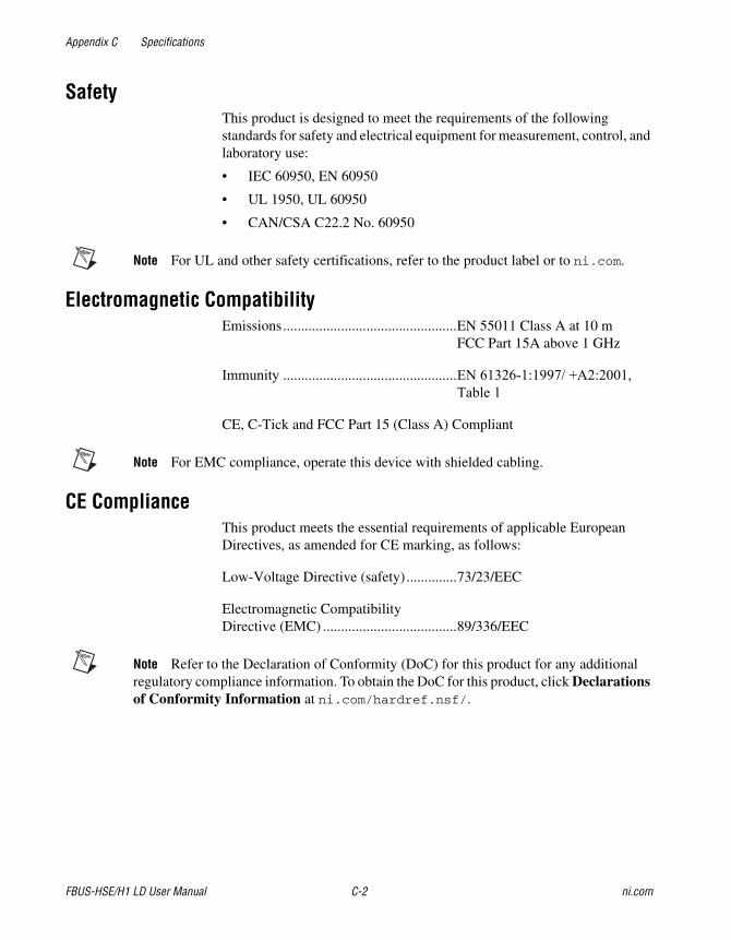
SafetyThis product is designed to meet the requirements of the following standards for safety and electrical equipment for measurement, control, and laboratory use:
• IEC 60950, EN 60950
• UL 1950, UL 60950
• CAN/CSA C22.2 No. 60950
Note For UL and other safety certifications, refer to the product label or to ni.com.
Electromagnetic CompatibilityEmissions................................................EN 55011 Class A at 10 m
FCC Part 15A above 1 GHz
Immunity ................................................EN 61326-1:1997/ +A2:2001, Table 1
CE, C-Tick and FCC Part 15 (Class A) Compliant
Note For EMC compliance, operate this device with shielded cabling.
CE ComplianceThis product meets the essential requirements of applicable European Directives, as amended for CE marking, as follows:
Low-Voltage Directive (safety)..............73/23/EEC
Electromagnetic Compatibility Directive (EMC) .....................................89/336/EEC
Note Refer to the Declaration of Conformity (DoC) for this product for any additional regulatory compliance information. To obtain the DoC for this product, click Declarations of Conformity Information at ni.com/hardref.nsf/.
© National Instruments Corporation D-1 FBUS-HSE/H1 LD User Manual
DTechnical Support and Professional Services
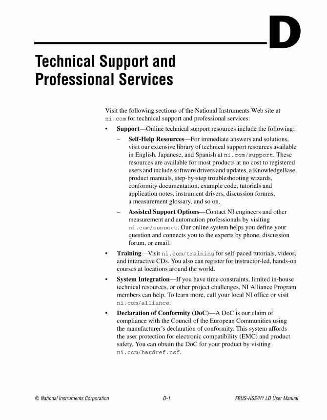
Visit the following sections of the National Instruments Web site at ni.com for technical support and professional services:
• Support—Online technical support resources include the following:
– Self-Help Resources—For immediate answers and solutions, visit our extensive library of technical support resources available in English, Japanese, and Spanish at ni.com/support. These resources are available for most products at no cost to registered users and include software drivers and updates, a KnowledgeBase, product manuals, step-by-step troubleshooting wizards, conformity documentation, example code, tutorials and application notes, instrument drivers, discussion forums, a measurement glossary, and so on.
– Assisted Support Options—Contact NI engineers and other measurement and automation professionals by visiting ni.com/support. Our online system helps you define your question and connects you to the experts by phone, discussion forum, or email.
• Training—Visit ni.com/training for self-paced tutorials, videos, and interactive CDs. You also can register for instructor-led, hands-on courses at locations around the world.
• System Integration—If you have time constraints, limited in-house technical resources, or other project challenges, NI Alliance Program members can help. To learn more, call your local NI office or visit ni.com/alliance.
• Declaration of Conformity (DoC)—A DoC is our claim of compliance with the Council of the European Communities using the manufacturer’s declaration of conformity. This system affords the user protection for electronic compatibility (EMC) and product safety. You can obtain the DoC for your product by visiting ni.com/hardref.nsf.
Appendix D Technical Support and Professional Services
FBUS-HSE/H1 LD User Manual D-2 ni.com
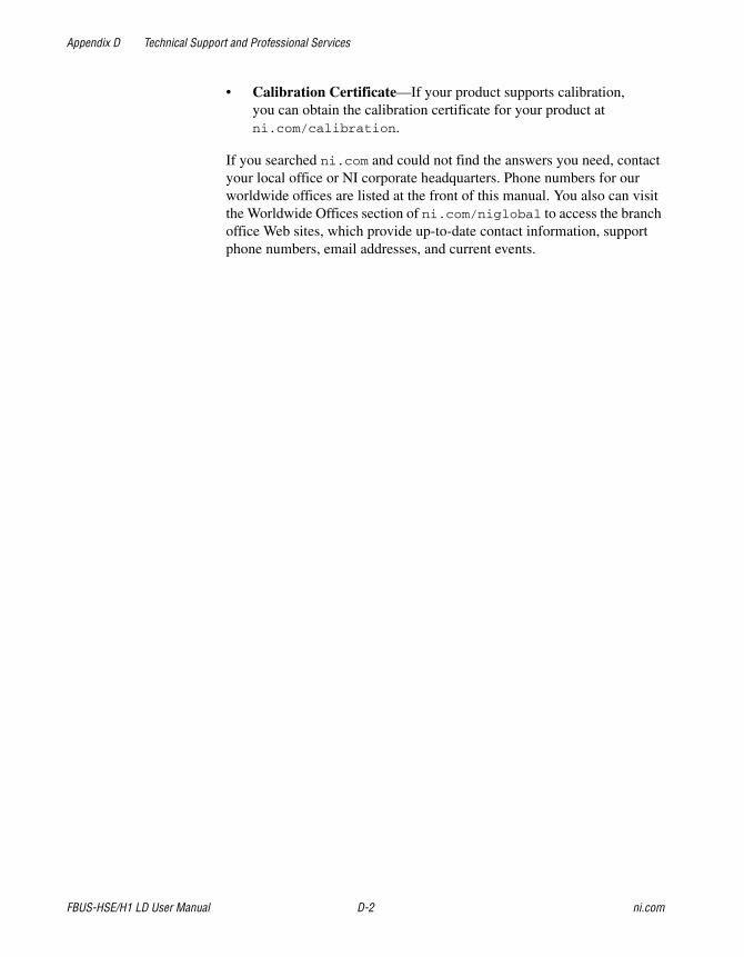
• Calibration Certificate—If your product supports calibration, you can obtain the calibration certificate for your product at ni.com/calibration.
If you searched ni.com and could not find the answers you need, contact your local office or NI corporate headquarters. Phone numbers for our worldwide offices are listed at the front of this manual. You also can visit the Worldwide Offices section of ni.com/niglobal to access the branch office Web sites, which provide up-to-date contact information, support phone numbers, email addresses, and current events.
© National Instruments Corporation G-1 FBUS-HSE/H1 LD User Manual
Glossary
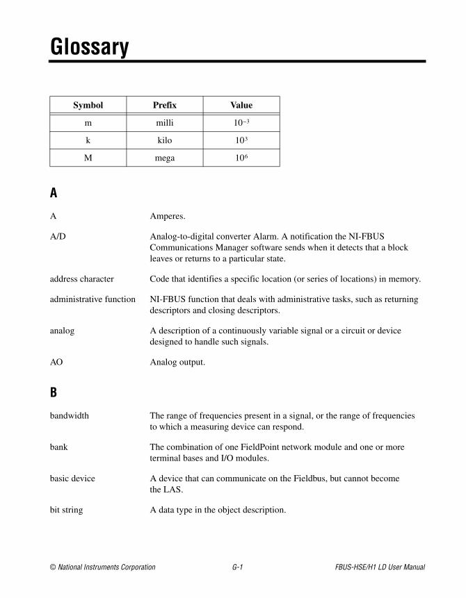
Symbol Prefix Value
m milli 10–3
k kilo 103
M mega 106
A
A Amperes.
A/D Analog-to-digital converter Alarm. A notification the NI-FBUS Communications Manager software sends when it detects that a block leaves or returns to a particular state.
address character Code that identifies a specific location (or series of locations) in memory.
administrative function NI-FBUS function that deals with administrative tasks, such as returning descriptors and closing descriptors.
analog A description of a continuously variable signal or a circuit or device designed to handle such signals.
AO Analog output.
B
bandwidth The range of frequencies present in a signal, or the range of frequencies to which a measuring device can respond.
bank The combination of one FieldPoint network module and one or more terminal bases and I/O modules.
basic device A device that can communicate on the Fieldbus, but cannot become the LAS.
bit string A data type in the object description.
Glossary
FBUS-HSE/H1 LD User Manual G-2 ni.com
Boolean Logical relational system having two values, each the opposite of the other, such as true and false or zero and one.
bps Bits per second.
buffer Temporary storage for acquired or generated data.
bus The group of conductors that interconnect individual circuitry in a computer. Typically, a bus is the expansion vehicle to which I/O or other devices are connected. Examples of PC busses are the ISA and PCI buses.
C
C Celsius.
cable A number of wires and shield in a single sheath.
channel A pin or wire lead to which you apply or from which you read the analog or digital signal.
circuit Interconnection of components to provide an electrical path between two or more components.
CISPR International Special Committee On Radio Interference.
control loop A set of connections between blocks used to perform a control algorithm.
controller An intelligent device, usually involving a CPU, that is capable of controlling other devices.
current The flow of electrons through a conductor.
D
DC Direct current.
descriptor A number returned to the application by the NI-FBUS Communications Manager, used to specify a target for future NI-FBUS calls.
device A sensor, actuator, or control equipment attached to the Fieldbus.
device ID An identifier for a device that the manufacturer assigns. No two devices can have the same device ID.
Glossary
© National Instruments Corporation G-3 FBUS-HSE/H1 LD User Manual
device tag A name you assign to a Fieldbus device.
DI Discrete input.
digital Pertaining to data (signals) in the form of discrete (separate/pulse form) integral values.
directory A structure for organizing files into convenient groups. A directory is like an address showing where files are located. A directory can contain files or subdirectories of files.
distributed control Process control distributed among several devices connected by a network.
DO Discrete output.
E
EMI Electromagnetic interference.
event Occurrence on a device that causes a Fieldbus entity to send the Fieldbus event message.
F
FBUS Fieldbus.
FBUS-HSE/H1 LD Fieldbus High Speed Ethernet to Foundation H1 Linking Device.
FF Foundation Fieldbus.
field device A Fieldbus device connected directly to a Fieldbus.
Fieldbus An all-digital, two-way communication system that connects control systems to instrumentation. A process-control local area network defined by ISA standard S50.02.
Fieldbus cable Shielded, twisted pair cable made specifically for Fieldbus that has characteristics for good signal transmission within the requirements of the Fieldbus standard.
Foundation Fieldbus Organization that developed a Fieldbus network specifically based upon the work and principles of the ISA/IEC standards committees.
Glossary
FBUS-HSE/H1 LD User Manual G-4 ni.com
Fieldbus network address
Location of a board or device on the Fieldbus; theFieldbus node address.
Foundation Fieldbus specification
Communications network specification created by the Fieldbus Foundation.
G
ground An intentional or accidental conducting path between an electrical system or circuit and the earth or some conducting body acting in place of the earth. A ground is often used as the common wiring point or reference in a circuit.
H
H1 31.25 kbit/second type of Fieldbus.
HotPnP Hot Plug and Play.
HSE High Speed Ethernet.
HSE-LD High Speed Ethernet linking device.
Hz Hertz.
I
I/O Input/output.
IEC International Electrotechnical Commission. A technical standards committee at the same level of ISO.
ISA Industry Standard Architecture.
isolation Type of signal conditioning in which the transducer signals are isolated from the computer for safety purposes. This protects you and your computer from large voltage spikes and makes sure the measurements from the devices are not affected by differences in ground potential.
Glossary
© National Instruments Corporation G-5 FBUS-HSE/H1 LD User Manual
L
LAS See Link Active Scheduler.
LD Linking device.
LED Light-emitting diode.
link A Foundation Fieldbus network is made up of devices connected by a serial bus. This serial bus is called a link. Also known as a segment.
Link Active Scheduler Fieldbus device currently controlling access to the Fieldbus. A device that is responsible for keeping a link operational. The LAS executes the link schedule, circulates tokens, distributes time, and probes for new devices.
link master device A device capable of becoming the LAS.
linkage A connection between function blocks.
loop See control loop.
M
menu An area accessible from the command bar that displays a subset of the possible command choices. In the NI-FBUS Configuration, refers to menus defined by the manufacturer for a given block.
method A method describes operating procedures to guide a user through a sequence of actions.
m Meter.
mm Millimeter.
mode Type of communication.
N
network address Fieldbus network address of a device.
nifb.exe NIFB process that must be running in the background for you to use your Linking Device to communicate between the board and Fieldbus.
Glossary
FBUS-HSE/H1 LD User Manual G-6 ni.com
node Junction or branch point in a circuit.
non-volatile memory Memory that does not require electricity to hold data.
O
object An element of an object dictionary.
P
parameter One of a set of network-visible values that makes up a function block.
PC Personal computer.
polarity Term used to describe positive and negative charges.
poll To repeatedly inspect a variable or function block to acquire data.
port A communications connection on a computer or remote controller.
POST Power-on self test.
program A set of instructions the computer can follow, usually in a binary file format, such as an .exe file.
R
RA Ratio.
repeater Boost the signals to and from the further link.
resistor Component made of material that opposes the flow of current and therefore has some value of resistance.
S
s Seconds.
scheduled communications
Communications that occur at the same time during each control cycle.
Glossary
© National Instruments Corporation G-7 FBUS-HSE/H1 LD User Manual
sensor A device that responds to a physical stimulus (heat, light, sound, pressure, motion, flow, and so on), and produces a corresponding electrical signal.
server Device that receives a message request.
service A service allows user applications to send messages to each other across Fieldbus using a standard set of message formats.
T
tag A name you can define for a block, virtual field device, or device.
terminator A device used to absorb the signal at the end of a wire.
timeout A period of time after which an error condition is raised if some event has not occurred.
U
unscheduled Messages sent on the Fieldbus between transmissions of scheduled messages.
upstream Fewer network hops away from a backbone or hub. For example, a small ISP connects to the Internet through a larger ISP that has its own connection to the backbone and is downstream from the larger ISP. The larger ISP is considered to be upstream from the smaller ISP.
V
V Volts.
VDC Volts direct current.
VFD See virtual field device.
virtual field device A model for remotely viewing data described in the object dictionary. The services provided by the Fieldbus Messaging Specification allow you to read and write information about the object dictionary, read and write the data variables described in the object dictionary, and perform other activities such as uploading/downloading data and invoking programs inside a device. A model for remotely viewing data is described in the object dictionary.
Glossary
FBUS-HSE/H1 LD User Manual G-8 ni.com
W
Waveform Multiple voltage readings taken at a specific sampling rate.
© National Instruments Corporation I-1 FBUS-HSE/H1 LD User Manual
Index
Ccables, 2-5calibration certificate, D-2CE compliance, C-2compatibility information, 1-3configuration and monitoring, 1-2connecting to the Fieldbus network, 2-6connector pinout (figure), 2-6contacting National Instruments, D-2conventions used in the manual, viicustomer
education, D-1professional services, D-1technical support, D-1
DDeclaration of Conformity, D-1diagnostic resources, D-1documentation
conventions used in the manual, viihow to use manual set, viionline library, D-1related documentation, viii
driversinstrument, D-1software, D-1
Eelectromagnetic compatibility
specifications, C-2environmental specifications, C-1
Ethernetcable pinouts (figure), 2-5cable wiring connections (table), 2-5connecting to the network, 2-3typical network setup (figure), 1-2
Ethernet LEDsLINK, B-2POWER, B-2PROCESS, B-2RX, B-2STATUS, B-2TX, B-2
Ethernet STATUS LED flashes and corresponding errors (table), B-4
example code, D-1
FFBUS-HSE/H1 Linking Device (LD)
configuration and monitoring, 1-2connecting to the Fieldbus network, 2-6connector pinout (figure), 2-6connectors (figure), 2-4description, 1-3Ethernet
cable pinouts (figure), 2-5cable wiring connections (table), 2-5connecting to the network, 2-3
installation and configuration, 2-1installing the network panel accessory
(figure), 2-3
Index
FBUS-HSE/H1 LD User Manual I-2 ni.com
LEDsEthernet LEDs, B-5Ethernet STATUS LED flashes and
corresponding errors (table), B-4figure, B-2H1 network status LEDs (table), B-5module STATUS LED (table), B-4troubleshooting, B-1
mounting on a DIN rail (figure), 2-2mounting to a panel, 2-3overview, 1-1power connection, 2-7
pinout (figure), 2-7power on, 2-7resetting, A-1
reset switch (figure), A-2system requirements, 1-3typical Ethernet network
setup (figure), 1-2Fieldbus network
connecting to, 2-6status LEDs, B-5
HH1 network
connecting to, 2-6status LEDs, B-5
hardwareconfiguration and monitoring, 1-2connecting to the Fieldbus network, 2-6connector pinout (figure), 2-6connectors (figure), 2-4description, 1-3Ethernet
cable pinouts (figure), 2-5cable wiring connections (table), 2-5connecting to the network, 2-3typical network setup (figure), 1-2
Ethernet LEDsfigure, B-2LINK, B-2POWER, B-2PROCESS, B-2RX, B-2STATUS, B-2TX, B-2
installation and configuration, 2-1installing the network panel accessory
(figure), 2-3LEDs
Ethernet STATUSflashes and corresponding errors
(table), B-4H1 network status LEDs (table), B-5troubleshooting, B-1
module STATUS LED (table), B-4mounting on a DIN rail (figure), 2-2mounting to a panel, 2-3overview, 1-1power connection, 2-7
pinout (figure), 2-7power on, 2-7system requirements, 1-3
helpprofessional services, D-1technical support, D-1
high speed Ethernet (HSE), definition of, 1-1how to use manual set, viiHSE, 1-1
Iinstrument drivers, D-1
KKnowledgeBase, D-1
Index
© National Instruments Corporation I-3 FBUS-HSE/H1 LD User Manual
LLEDs
Ethernet LEDs, B-2figure, B-2H1 network status LEDs (table), B-5module STATUS LED (table), B-4on top panel (figure), B-1POWER, 2-7troubleshooting, B-1
Mmechanical dimensions, C-1module STATUS LED, B-4
NNational Instruments
calibration certificate, D-2customer education, D-1Declaration of Conformity, D-1professional services, D-1system integration services, D-1technical support, D-1worldwide offices, D-2
network specifications, C-1
Oonline technical support, D-1operating specifications, C-1
Pphone technical support, D-2power connection, 2-7
pinout (figure), 2-7power on, 2-7product overview, 1-1professional services, D-1programming examples, D-1
Rrelated documentation, viiireset switch (figure), A-2resetting, A-1
Ssoftware
HMI, 1-3NI-FBUS, using to configure Ethernet
settings, A-1system requirements, 1-3
software drivers, D-1specifications
CE compliance, C-2electromagnetic compatibility, C-2environmental, C-1mechanical dimensions, C-1network, C-1operating, C-1safety, C-2storage, C-1
support, technical, D-1system integration services, D-1system requirements
compatibility information, 1-3hardware, 1-3software, 1-3
Ttechnical support, D-1telephone technical support, D-2training, customer, D-1troubleshooting, B-1troubleshooting resources, D-1
Index
FBUS-HSE/H1 LD User Manual I-4 ni.com
WWeb
professional services, D-1technical support, D-1
worldwide technical support, D-2