Embed Size (px)
Citation preview

A R C H I V E 2 0 0 6A R C H I V E 2 0 0 6Tutorial
COPYRIGHT NOTICECOPYRIGHT NOTICE• The papers in this publication comprise the proceedings of the 2006 BiTS Workshop. They reflect the authors’ opinions and are reproduced as presented , without change. Their inclusion in this publication does not constitute an endorsement by the BiTS Workshop, the sponsors, BiTS Workshop LLC, or the authors.• There is NO copyright protection claimed by this publication or the authors. However, each presentation is the work of the authors and their respective companies: as such, it is strongly suggested that any use reflect proper acknowledgement to the appropriate source. Any questions regarding the use of any materials presented should be directed to the author/s or their companies.• The BiTS logo and ‘Burn-in & Test Socket Workshop’ are trademarks of BiTS Workshop LLC.
“Differential Impedance And Insertion Loss Applied To Sockets”
Eric BogatinChief Technical Officer
Synergetix

20062006 Tutorial 2
March 12 - 15, 2006 1
© Eric Bogatin 2006
Slide - 1Differential Impedance and Insertion Loss Applied to Sockets
2006 Burn-in and Test Socket WorkshopMarch 12-15, 2005
Differential Impedance and Insertion Differential Impedance and Insertion Loss Applied to SocketsLoss Applied to Sockets
Dr. Eric BogatinCTO, SynergetixKansas City, [email protected]
www.BeTheSignal.com © Eric Bogatin 2006
Slide - 2Differential Impedance and Insertion Loss Applied to Sockets
Outline
Who cares?
What design features influence insertion loss?
What is impedance
What design features influence impedance?
What is differential impedance
What design features influence differential impedance
What is differential insertion loss?
““It is better to uncover a little than to cover a lotIt is better to uncover a little than to cover a lot””-- Francis LowFrancis Low
© Eric Bogatin 2006
Slide - 3Differential Impedance and Insertion Loss Applied to Sockets
For More Information
www.BeTheSignal.comOnline LecturesFeature ArticlesPCD&M Monthly Signal Integrity Column: “No Myths Allowed”Master Class WorkshopsResources
Published by Prentice Hall, 2004
© Eric Bogatin 2006
Slide - 4Differential Impedance and Insertion Loss Applied to Sockets
Electrical Performance of Sockets in Perspective
• PerformanceCompliancePitchCycle lifetimeTime between cleaningElectrical
– DC resistance– Hi Frequency
– Signal Integrity» Bandwidth» Insertion loss» Return loss» SPICE models
– Power integrity» Loop inductance
Cost: $$$, TCOO,
Schedule, Risk
Constraints:• Vendors• Corporate Culture• Compatibility: Industry, Legacy
Partitioning:• Pin electronics• Wiring/cabling• Loadboards• Sockets
© Eric Bogatin 2006
Slide - 5Differential Impedance and Insertion Loss Applied to Sockets
The Socket as a Component
• Purpose of an interconnect: “to transport a signal from one point to another with an acceptable level of distortion”
What’s important to know? 1. Will the system work?2. Is the socket “good enough?”3. How do you know before you build it and test it?
Simulated with HyperLynx
© Eric Bogatin 2006
Slide - 6Differential Impedance and Insertion Loss Applied to Sockets
3rd Best Alternative
• Specify values of model (circuit or behavioral) parametersZ0TDLCInsertion lossReturn loss
• Specifications based on assumptionsassumptions of the rest of the system
• Specifications are a pre-arranged compromise- sometimes based on:System level simulation balancing cost-performance-constraints- (really hard!)A guessBecause it worked in the last designEnough margin for designer to sleep at nightAssuming performance is freeIncorrect assumptionsInformation that was passed from engineer to engineer to engineer to engineer…(only one of whom might have an idea of what they want)
20062006 Tutorial 2
March 12 - 15, 2006 2
© Eric Bogatin 2006
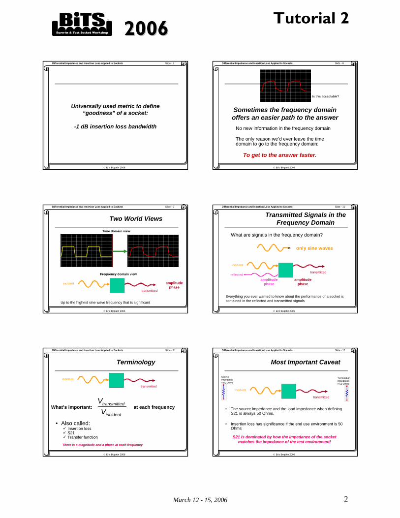
Slide - 7Differential Impedance and Insertion Loss Applied to Sockets
Universally used metric to define “goodness” of a socket:
-1 dB insertion loss bandwidth
© Eric Bogatin 2006
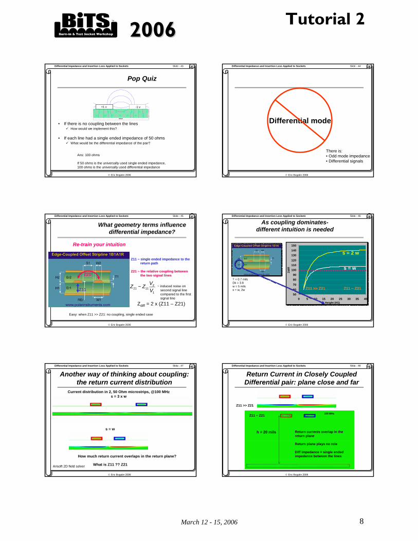
Slide - 8Differential Impedance and Insertion Loss Applied to Sockets
Sometimes the frequency domain offers an easier path to the answer
No new information in the frequency domain
The only reason we’d ever leave the time domain to go to the frequency domain:
To get to the answer faster.
Is this acceptable?
© Eric Bogatin 2006
Slide - 9Differential Impedance and Insertion Loss Applied to Sockets
Two World Views
Time domain view
amplitudephase
incident
transmitted
Frequency domain view
Up to the highest sine wave frequency that is significant
© Eric Bogatin 2006
Slide - 10Differential Impedance and Insertion Loss Applied to Sockets
Transmitted Signals in the Frequency Domain
What are signals in the frequency domain?
only sine waves
amplitudephase
amplitudephase
incident
transmittedreflected
Everything you ever wanted to know about the performance of a socket is contained in the reflected and transmitted signals
© Eric Bogatin 2006
Slide - 11Differential Impedance and Insertion Loss Applied to Sockets
Terminology
• Also called:Insertion lossS21Transfer function
incident
transmitted
What’s important: incident
dtransmitte
VV
at each frequency
There is a magnitude and a phase at each frequencyThere is a magnitude and a phase at each frequency
© Eric Bogatin 2006
Slide - 12Differential Impedance and Insertion Loss Applied to Sockets
Most Important Caveat
• The source impedance and the load impedance when defining S21 is always 50 Ohms.
• Insertion loss has significance if the end use environment is 50Ohms
incident
transmitted
Source impedance = 50 Ohms
Termination impedance = 50 Ohms
S21 is dominated by how the impedance of the socket S21 is dominated by how the impedance of the socket matches the impedance of the test environment!matches the impedance of the test environment!

20062006 Tutorial 2
March 12 - 15, 2006 3
© Eric Bogatin 2006
Slide - 13Differential Impedance and Insertion Loss Applied to Sockets
Good and Bad Insertion Loss
• Is there a difference betweengoodgood enoughbetter ?
2 4 6 8 10 12 14 16 180 20
0.10.20.30.40.50.60.70.80.9
0.0
1.0
freq, GHz
Inse
rtion
Los
s (m
agni
tude
)
2 4 6 8 10 12 14 16 180 20
0.10.20.30.40.50.60.70.80.9
0.0
1.0
freq, GHz
Inse
rtion
Los
s (m
agni
tude
)
good
badIs this good? Is it good enough?
Simulated with Agilent ADS
-1 dB = 90% transmitted signal amplitude-2 dB = 80% transmitted signal amplitude-3 dB = 70% transmitted signal amplitude
© Eric Bogatin 2006
Slide - 14Differential Impedance and Insertion Loss Applied to Sockets
The Value of “-1 dB Insertion Loss Bandwidth” as a Metric
• Relative comparison
• First pass screening
• Rough, rule of thumb for usable operating frequency
• Should not be used to sign off on a designtoo approximate
too much margin? Too little?
Too many assumptions
• Multiple approximations:Bandwidth of the signal
Is the system a 50 Ohm system?
Total system budget
Allocation to the socket
• A better approach (and much more expensive):Model and simulate
© Eric Bogatin 2006
Slide - 15Differential Impedance and Insertion Loss Applied to Sockets
What Affects Insertion Loss of a Socket?
1. Matched Impedance
2. Controlled impedance
3. Discontinuities of load board
4. Length
5. Dielectric loss
6. Conductor loss
7. DC contact resistance
© Eric Bogatin 2006
Slide - 16Differential Impedance and Insertion Loss Applied to Sockets
The Simplest Model of a Transmission Line
A "-1" order model:Any two conductors with length
Lead frame of an IC Package
Microstrip
Length
© Eric Bogatin 2006
Slide - 17Differential Impedance and Insertion Loss Applied to Sockets
Labeling the Conductors
Signal path
Return pathGROUND
© Eric Bogatin 2006
Slide - 18Differential Impedance and Insertion Loss Applied to Sockets
The Signal
GROUND
VVsignal
Signal path
Return pathVVin

20062006 Tutorial 2
March 12 - 15, 2006 4
© Eric Bogatin 2006
Slide - 19Differential Impedance and Insertion Loss Applied to Sockets
signal
returnε
How fast does a signal move down a line?
in air: v = 186,000 miles per sec v = 12 inches/nsec
secsecsec 6
212
412
ninchesn
inchesn
inches
v ===
v
© Eric Bogatin 2006
Slide - 20Differential Impedance and Insertion Loss Applied to Sockets
Instantaneous Impedance
VVsignal
Signal path
Return path
• Signal sees an “instantaneous impedance” each step along the path• Instantaneous impedance depends on the geometry of signal and return path• A controlled impedance when instantaneous impedance is constant• One impedance that characterizes the interconnect:
• Characteristic impedance
© Eric Bogatin 2006
Slide - 21Differential Impedance and Insertion Loss Applied to Sockets
Characteristic Impedance and Capacitance per Length
capacitance per length decreases, the characteristic impedance increases
h = 5 mils
w = 10 mils
50 Ohm PCB cross section
increase h
the capacitance per length increases, characteristic impedance decreasesincrease w
Z CL0
1~
© Eric Bogatin 2006
Slide - 22Differential Impedance and Insertion Loss Applied to Sockets
Most Important Features of Characteristic Impedance
• Characteristic impedance is not about the signal path
• Characteristic impedance is not about the return path
• Characteristic impedance will depend both signal and return path, inseparably
• There is no such thing as the characteristic impedance of a single pin
• Change the return path configuration, you change the characteristic impedance
•• (Obviously, the same goes for insertion loss!)(Obviously, the same goes for insertion loss!)
© Eric Bogatin 2006
Slide - 23Differential Impedance and Insertion Loss Applied to Sockets
Return Path PatternsReturn Path Patterns
Return Path Selection Strongly Influences Single Ended Impedance
© Eric Bogatin 2006
Slide - 24Differential Impedance and Insertion Loss Applied to Sockets
Ideal, Lossless transmission lines have just Two Parameters:
• Characteristic Impedance: Z0• Time delay: TD

20062006 Tutorial 2
March 12 - 15, 2006 5
© Eric Bogatin 2006
Slide - 25Differential Impedance and Insertion Loss Applied to Sockets
Pattern 2a: current flow at 20 GHz
sig retret
Agilent ADS Momentum
© Eric Bogatin 2006
Slide - 26Differential Impedance and Insertion Loss Applied to Sockets
How well do these pins look like an ideal transmission line?
?=
© Eric Bogatin 2006
Slide - 27Differential Impedance and Insertion Loss Applied to Sockets
All Transmission Lines with the Same Characteristic Impedance and Time Delay Behave Exactly the Same
2 4 6 8 10 12 14 16 180 20
-100
0
100
-200
200
freq, GHz
phas
e(S
(1,1
))ph
ase(
S(3
,3))
2 4 6 8 10 12 14 16 180 20
-60
-40
-20
-80
0
freq, GHz
dB(S
(1,1
))dB
(S(3
,3))
2 4 6 8 10 12 14 16 180 20
-100
-50
-150
0
freq, GHz
phas
e(S(
2,1)
)ph
ase(
S(4,
3))
2 4 6 8 10 12 14 16 180 20
-1.5
-1.0
-0.5
-2.0
0.0
freq, GHz
dB(S
(2,1
))dB
(S(4
,3))
3D EM sim of the pin fieldSimulated ideal transmission line (Z0 = 42 ohms)
Return Loss Insertion Loss
BW of the model ~ 12 GHzBW of the model ~ 12 GHz
Agilent ADS
© Eric Bogatin 2006
Slide - 28Differential Impedance and Insertion Loss Applied to Sockets
Minimizing Insertion Loss Principle #1: Match Impedance to 50 Ohms
1. Uniform impedance interconnect2. Match socket to 50 Ohms3. Keep: 30 Ohms < Z0 < 80 Ohms and insertion loss will never be
greater than -1 dB
Z0 = 80 OhmsZ0 = 30 OhmsZ0 = 20 Ohms
2 4 6 8 10 12 14 16 180 20
-4
-3
-2
-1
-5
0
freq, GHz
Inse
rtion
Los
s, d
B
Simulated with Agilent ADS
© Eric Bogatin 2006
Slide - 29Differential Impedance and Insertion Loss Applied to Sockets
What if the Impedance is not Controlled?
2 4 6 8 10 12 14 16 180 20
-4
-3
-2
-1
-5
0
freq, GHz
Inse
rtion
Los
s, d
B
30Ω 80Ω
• Low frequency behavior is related to ~ average impedance- can be better than either one• Highest insertion loss can be much worse than either discontinuity (> 3x)
Total length = 0.2 inches
© Eric Bogatin 2006
Slide - 30Differential Impedance and Insertion Loss Applied to Sockets
Three Impedance Discontinuities
2 4 6 8 10 12 14 16 180 20
-7
-6
-5
-4
-3
-2
-1
-8
0
freq, GHz
Inse
rtion
Los
s, d
B
30Ω 80Ω
Total length = 0.2 inches
30Ω 80Ω 30Ω
• Low frequency behavior is related to ~ average impedance- can be better than either one• Highest insertion loss can be much worse than either discontinuity (> 7x)

20062006 Tutorial 2
March 12 - 15, 2006 6
© Eric Bogatin 2006
Slide - 31Differential Impedance and Insertion Loss Applied to Sockets
Minimizing Insertion Loss Principle #2: Use a controlled impedance interconnect
• Match average impedance to 50 Ohms
• Design for controlled impedance- uniform cross section
© Eric Bogatin 2006
Slide - 32Differential Impedance and Insertion Loss Applied to Sockets
7 Principles of Socket Design for Optimized Insertion Loss
1. match characteristic impedance of socket to 50 Ohms2. Keep the impedance constant through socket3. Optimize (minimize) pad stack up capacitance 4. Keep socket short (shorter is better, but long may be
good enough)5. Dielectric loss of socket not critical6. Conductor loss of socket not critical7. Contact resistance of socket not critical
© Eric Bogatin 2006
Slide - 33Differential Impedance and Insertion Loss Applied to Sockets
The Highest Speed Signals Are All Differential
• Serial Data Interface (SDI): 0.27 1.488 Gbps/pin
• HyperTransport: 0.4 1.2 Gbps/pin
• Fibre Channel: 1.062 2.125 4.25 Gbps/pin
• Serial RapidIO™: 1.25 2.5 3.125 Gbps/pin
• PCI Express: 2.5 5 Gbps/pin
• XAUI 3.125 6.25 Gbps/pin
• Proprietary (Basic) x 2x 3x Gbps/pin
© Eric Bogatin 2006
Slide - 34Differential Impedance and Insertion Loss Applied to Sockets
What is a differential signal?
Example: National Semi DS92LV010A Output swing: 1.125v to 1.375 v into 27 Ohm load
V1, V2
V = V1 - V2
© Eric Bogatin 2006
Slide - 35Differential Impedance and Insertion Loss Applied to Sockets
Differential and Common Signals
2V1VVdiff −= ( )2V1V21Vcomm +=
There is a large common voltage component!
Vdiff
Vcomm
© Eric Bogatin 2006
Slide - 36Differential Impedance and Insertion Loss Applied to Sockets
Courtesy of ALTERA Corp.
Differential Signals
Note: There Is a Very Large Common Component
0.6 V0.6 V
1.2 V0.4 V
1.9 V0.4 V
3.15 V0.3 V
Comm SignalDiff Signal
Differential I/O Standards Supported By Altera® Stratix® Devices
4.0
3.0
2.0
1.0
0.0
Volta
ge (V
)
Technology
PCLM3.3 V
3.0 V
LVPECL1.7 V
2.1 V
LVDS
Hyper-Transport
1.4 V
1.0 V0.9 V
0.3 V

20062006 Tutorial 2
March 12 - 15, 2006 7
© Eric Bogatin 2006
Slide - 37Differential Impedance and Insertion Loss Applied to Sockets
What’s a Differential Pair Transmission Line?
Answer: …..any two, coupled transmission lines (with their return paths).
WhatWhat’’s differential impedance?s differential impedance?
12
Optimized high speed performance for the special case: a symmetric pair, with matched time delay of both paths
© Eric Bogatin 2006
Slide - 38Differential Impedance and Insertion Loss Applied to Sockets
Very Important Principle!!
Differential impedance is the instantaneous impedance the
difference signal sees
© Eric Bogatin 2006
Slide - 39Differential Impedance and Insertion Loss Applied to Sockets
What is the Impedance the Differential Signal Sees?
Z0 Z0
The Differential Impedance
What is the impedance of each line?
Zdiff = Z0 + Z0
© Eric Bogatin 2006
Slide - 40Differential Impedance and Insertion Loss Applied to Sockets
“…It Depends”
• No coupling: Z0 = single-ended characteristic impedance
• With coupling: depends on how the other line is driven
Other line is tied lowOther line is driven opposite (differential signal)Other line is driven the same(common signal)
© Eric Bogatin 2006
Slide - 41Differential Impedance and Insertion Loss Applied to Sockets
Other Line Is Tied Low
Second Trace Pegged Low
40
42
44
46
48
50
52
54
56
58
0 5 10 15 20 25 30 35 40 45 50
Edge to Edge Spacing Between the Traces (mils)
Sing
le-E
nded
Impe
danc
e (O
hms)
Z0, Second Trace Pegged Low
Polar Instruments SI8000
© Eric Bogatin 2006
Slide - 42Differential Impedance and Insertion Loss Applied to Sockets
Other Line Driven Opposite
return
+1 v -1 v
Differential SignalOdd Mode State
40
42
44
46
48
50
52
54
56
58
0 5 10 15 20 25 30 35 40 45 50
Edge to Edge Spacing Between the Traces (mils)
Sing
le-E
nded
Impe
danc
e (O
hms)
Z0, Second Trace Pegged Low
Z0, Both Traces Driven Opposite
Zdiff = 2 x Zodd
20062006 Tutorial 2
March 12 - 15, 2006 8
© Eric Bogatin 2006
Slide - 43Differential Impedance and Insertion Loss Applied to Sockets
Pop Quiz
return
+1 v -1 v
• If there is no coupling between the linesHow would we implement this?
• If each line had a single ended impedance of 50 ohmsWhat would be the differential impedance of the pair?
Ans: 100 ohms
If 50 ohms is the universally used single ended impedance, 100 ohms is the universally used differential impedance
© Eric Bogatin 2006
Slide - 44Differential Impedance and Insertion Loss Applied to Sockets
Differential mode
There is:• Odd mode impedance• Differential signals
© Eric Bogatin 2006
Slide - 45Differential Impedance and Insertion Loss Applied to Sockets
What geometry terms influence differential impedance?
Re-train your intuition
Z21Z21
Z11Z11
Z11 ~ single ended impedance to the Z11 ~ single ended impedance to the return pathreturn path
Z21 ~ the relative coupling between Z21 ~ the relative coupling between the two signal linesthe two signal lines
Zdiff = 2 x (Z11 – Z21)
Easy: when Z11 >> Z21: no coupling, single ended case
1
21121 ~
VVZZ ~ induced noise on
second signal line compared to the first signal line
© Eric Bogatin 2006
Slide - 46Differential Impedance and Insertion Loss Applied to Sockets
5060708090
100110120130140150
0 5 10 15 20 25 30 35 40Height (H1)
Zdiff
5060708090
100110120130140150
0 5 10 15 20 25 30 35 40Height (H1)
Zdiff
As coupling dominates-different intuition is needed
s = w
s = 2 w
T = 0.7 milsDk = 3.8w = 5 milss = w, 2w Z11 ~ Z21Z11 ~ Z21Z11 >> Z21Z11 >> Z21
© Eric Bogatin 2006
Slide - 47Differential Impedance and Insertion Loss Applied to Sockets
Another way of thinking about coupling: the return current distribution
How much return current overlaps in the return plane?
Current distribution in 2, 50 Ohm microstrips, @100 MHzs = 3 x w
s = w
What is Z11 ?? Z21Ansoft 2D field solver
© Eric Bogatin 2006
Slide - 48Differential Impedance and Insertion Loss Applied to Sockets
Return Current in Closely Coupled Differential pair: plane close and far
h = 20 mils
100 MHz
Z11 >> Z21
Z11 ~ Z21
Return currents overlap in the return plane
Return plane plays no role
Diff impedance = single ended impedance between the lines

20062006 Tutorial 2
March 12 - 15, 2006 9
© Eric Bogatin 2006
Slide - 49Differential Impedance and Insertion Loss Applied to Sockets
If Signal To Signal Coupling Is Much Tighter Than Signal To Return
0
20
40
60
80
100
120
140
0 5 10 15 20 25 30 35 40 45 50
Plane to Trace Separation, h (mils)
Diff
eren
tial I
mpe
danc
e (O
hms)
Return current is carried by adjacent trace when the signal lines in the differential pair look like two isolated traces as part of a single ended transmission line.
h = 20 mils
100 MHz
Current density scale expanded by 10x
Return current carried by adjacent trace
© Eric Bogatin 2006
Slide - 50Differential Impedance and Insertion Loss Applied to Sockets
When signal to signal coupling dominates- all return currents in planes overlap and cancel out. Planes play
no role in diff impedance
5060708090
100110120130140150160170
0 5 10 15 20 25Separation, s
Zdiff
w = 5 mils
s
Dielectric thickness very large
© Eric Bogatin 2006
Slide - 51Differential Impedance and Insertion Loss Applied to Sockets
Return Currents in Differential Pairs
Most return current is carried by the plane when signal to return coupling >> signal to signal coupling
Ex: most board level interconnects
Most return current is carried by the other signal when signal to plane coupling << signal to signal coupling
Ex: most connectors, shielded twisted pair, twisted pair, sockets
Mentor Graphics Hyperlynx
© Eric Bogatin 2006
Slide - 52Differential Impedance and Insertion Loss Applied to Sockets
Single ended current in (-) pin
@ 10 MHz
What would 1 GHz look like?
@ 10 MHz
return+ signal(floating) - signal
Magnitude of current
XooX
© Eric Bogatin 2006
Slide - 53Differential Impedance and Insertion Loss Applied to Sockets
Single ended signal in (+) pin
@ 10 MHz
return+ signal - signal(floating)
ooX X oo
© Eric Bogatin 2006
Slide - 54Differential Impedance and Insertion Loss Applied to Sockets
Return Current for Differential Signal: Pattern 1a
return+ signal - signal
@ 10 MHz
Small amount of residual return current- mostly cancelled out
XooX

20062006 Tutorial 2
March 12 - 15, 2006 10
© Eric Bogatin 2006
Slide - 55Differential Impedance and Insertion Loss Applied to Sockets
Differential Impedance Between the two pins, as return is moved away
0
10
20
30
40
50
60
70
80
90
100
0 1 2 3 4 5
Spacing to Return Pin, mm
Diff
Impe
danc
e, O
hms
s
When return currents overlap, differential impedance is independent of the return path
© Eric Bogatin 2006
Slide - 56Differential Impedance and Insertion Loss Applied to Sockets
Return current distribution, differential pattern 2a
return + signal - signal return
Distinct return current in return
pins
Distinct return current in return
pins
© Eric Bogatin 2006
Slide - 57Differential Impedance and Insertion Loss Applied to Sockets
Differential Impedance of Pattern 2a, as returns are moved away
0
10
20
30
40
50
60
70
80
90
100
0 1 2 3 4 5
Spacing to Return Pin, mm
Diff
Impe
danc
e, O
hms
pattern 2a
pattern 1a
Very important conclusion:Very important conclusion:
To 1To 1stst order, the differential impedance of a pair of pins is the order, the differential impedance of a pair of pins is the single ended impedance of the pair of pinssingle ended impedance of the pair of pins
© Eric Bogatin 2006
Slide - 58Differential Impedance and Insertion Loss Applied to Sockets
An Introduction to Differential S Parameters
© Eric Bogatin 2006
Slide - 59Differential Impedance and Insertion Loss Applied to Sockets
DUTIncident Wave
Reflected Wave
Transmitted Wave
S11
S21
Incident Wave
Reflected Wave
Transmitted Wave
TDR
TDTt
t
DUT
Characterizing Interconnects in Time and Frequency Domains
© Eric Bogatin 2006
Slide - 60Differential Impedance and Insertion Loss Applied to Sockets
Behavioral Models From Scattering
• All the electrical properties of an interconnect are described by how signals scatter from it: “Scattering” or S-parameters
Incident
Port 1
Port 2
Port 3Port 4
Port 5
Port 6Port 7

20062006 Tutorial 2
March 12 - 15, 2006 11
© Eric Bogatin 2006
Slide - 61Differential Impedance and Insertion Loss Applied to Sockets
4-Port Single-Ended S-Parameters Matrix for Differential Channel Characterization
1
3
2
4(and their return paths!)
44434241
34333231
24232221
14131211
SSSSSSSSSSSSSSSS
Stimulus
Res
pons
e Interpreting Single-Ended Measurements:S11: return loss, single endedS21= S12: insertion loss, single endedS31= S13: near-end cross talkS41= S14: far-end cross talk
in
outin,out V
VS =
© Eric Bogatin 2006
Slide - 62Differential Impedance and Insertion Loss Applied to Sockets
Differential S-Parameters
Differential Pair Port 1
Differential Pair Port 2(and their return paths!)
Stimulus Differential Signal Common Signal
port 1 port 2 port 1 port 2
port 1 SDD11 SDD12 SDC11 SDC12
Diff
eren
tial
Sign
al
port 2 SDD21 SDD22 SDC21 SDC22
port 1 SCD11 SCD12 SCC11 SCC12
Res
pons
e C
omm
on
Sign
al
port 2 SCD21 SCD22 SCC21 SCC22
1
3
2
4(and their return paths!) =
© Eric Bogatin 2006
Slide - 63Differential Impedance and Insertion Loss Applied to Sockets
4-Port S-Parameter Matrices
Single Ended Differential, Mixed Mode, Balanced
Mathematical Transform
© Eric Bogatin 2006
Slide - 64Differential Impedance and Insertion Loss Applied to Sockets
Differential Insertion Loss: SDD21
Sdd11(2,1) = 0.5 x (S(2,1) - S(2,3) - S(4,1) + S(4,3))
single13
24
diff1 2
Measure the single ended S parameters values
© Eric Bogatin 2006
Slide - 65Differential Impedance and Insertion Loss Applied to Sockets
Minimizing Insertion Loss Principle #1: Match Differential Impedance to 100 Ohms
1. Uniform impedance interconnect2. Match socket to 100 Ohms3. Keep: 60 Ohms < Z0 < 160 Ohms and insertion loss will never be
greater than -1 dB
Z0 = 160 OhmsZ0 = 60 OhmsZ0 = 40 Ohms
2 4 6 8 10 12 14 16 180 20
-4
-3
-2
-1
-5
0
freq, GHz
Inse
rtion
Los
s, d
B
Simulated with Agilent ADS
© Eric Bogatin 2006
Slide - 66Differential Impedance and Insertion Loss Applied to Sockets
7 Principles of Socket Design for Optimized Differential Insertion Loss
1. Match differential impedance of socket to 100 Ohms2. Keep the impedance constant through socket3. Optimize (minimize) pad stack up capacitance 4. Keep socket short (shorter is better, but long may be
good enough)5. Dielectric loss of socket not critical6. Conductor loss of socket not critical7. Contact resistance of socket not critical

20062006 Tutorial 2
March 12 - 15, 2006 12
© Eric Bogatin 2006
Slide - 67Differential Impedance and Insertion Loss Applied to Sockets
Summary
• Differential impedance will proliferate
• Differential impedance target is 100 ohms
• -1 dB Insertion loss bandwidth is a universally used metric for socket performance
• It is only a rough approximation to the end use performance
• Same intuition about single ended bandwidth performance applies to differential insertion loss bandwidth performance
© Eric Bogatin 2006
Slide - 68Differential Impedance and Insertion Loss Applied to Sockets
The End
Thanks for listening!
www.BeTheSignal.com


![TEE Sockets API Specification v1.0 - GlobalPlatform · TEE Sockets API Specification Annex A: TCP/IP Specification of TEE Sockets API Specification [Sockets TCP/IP] GPD_SPE_102 :](https://img.pdfslide.us/doc/110x75/60421070f2b21560856dea9a/tee-sockets-api-specification-v10-globalplatform-tee-sockets-api-specification.jpg)