Embed Size (px)
Citation preview
ISSN: 2277-9655
[Jain* et al., 6(2): February, 2017] Impact Factor: 4.116
IC™ Value: 3.00 CODEN: IJESS7
http: // www.ijesrt.com© International Journal of Engineering Sciences & Research Technology
[188]
IJESRT INTERNATIONAL JOURNAL OF ENGINEERING SCIENCES & RESEARCH
TECHNOLOGY
SEISMIC RESPONSE OF RC FRAMED MULTI-STOREY BUILDING WITH
FLOATING COLUMNS Shreyans Kumar Jain*, Prof. Nidhi Gupta
*Post Graduate Student in Structural Engineering, Department of Civil Engineering, RKDF-IST,
Bhopal M.P., India
DOI: 10.5281/zenodo.290143
ABSTRACT The present work deals with the study of comparative Seismic Response of RC Framed Multi-storey Buildings
with and without Floating Columns in various configurations and with different storey height. To carry out the
work two sets of models are taken which differs in storey height of ground floor. Both the sets contain seven
models (total fourteen) with different configuration and numbers of floating columns are considered. Various
gravity loads are applied and since building is assumed to be located in seismic zone IV, the seismic loads
considered accordingly. Models are developed and analysed with the help of STAAD.Pro V8i by performing
equivalent static analysis method. Results are obtained and compared in terms of various parameters such as
axial force, shear force, moments, node displacements, average storey displacement and storey drift. The study
concludes, inter alia, that the diagonal pattern of floating column is preferable as compare to orthogonal pattern
and maximum absolute value of the important design parameters appears at ground and first floors.
KEYWORDS: Floating Columns, Equivalent Static Analysis, Base Shear, Node Displacement, Storey
Displacement, Storey Drift
INTRODUCTION Few decades back the populations were not so vast so they used to stay in horizontal system (due to large area
available per person), but now a day’s people preferring Vertical System (high rise buildings) due to shortage of
area. This necessitated an infrastructural boom during last few decades which resulted in construction of many
high rise structures in all mega cities. Due to shortage of space, increasing population and also for aesthetic and
functional requirements, multi-storey buildings in urban cities are required to have column free space. For this,
buildings are provided with floating columns at one or more storey. The term floating column is a vertical
structural element which (due to architectural design/ site situation) at its lower level (termination level) rests on
a beam which is a horizontal member. The beams in turn transfer the load to other columns below it. There are
many projects in which floating columns are adopted, especially above the ground floor, where transfer girders
are employed, so that more open space is available in the ground floor. Today many multi-storeyed buildings in
India have floating columns as an unavoidable feature. Architects and Structural Designers have provided
floating column in many locations in structure.
Most of the time, architect demands for the aesthetic view of the building, in such cases also many of the
columns are terminated at certain floors and floating columns are introduced and hence such buildings are
planned and constructed with architectural complexities. However, this should not be done at the cost of poor
behaviour and earthquake safety of buildings. Architectural features that are detrimental to earthquake response
of buildings should be avoided and if not, they must be minimized. When irregular features such as above are
included in buildings, a considerably higher level of engineering effort is required in the structural planning &
design and yet the building may not be as good as one with simple architectural features. The discontinuity of
column at any floor changes the load path and transfers load of the floating column through horizontal beams
supporting it. This altered path will cause large vertical earthquake forces due to overturning effect.
Providing floating columns may satisfy some of the functional requirements but structural behaviour changes
abruptly. Where provision of floating column is necessary, special care should be given to the transfer girders

ISSN: 2277-9655
[Jain* et al., 6(2): February, 2017] Impact Factor: 4.116
IC™ Value: 3.00 CODEN: IJESS7
http: // www.ijesrt.com© International Journal of Engineering Sciences & Research Technology
[189]
and column below the floating column. These beams and column should have sufficient strength to receive the
load from floating column and convey it to the lower level.
Since the lateral load resisting system is often integrated with the gravity load resisting system, this can result in
serious damage or collapse of the building during seismic attack for presence of floating columns in a building
may result in a concentration of forces or deflection or in an undesirable load path in the vertical lateral-force-
resisting system. Vertical irregularities typically occur in a storey that is significantly more flexible or weaker
than adjacent stories due to many reasons. A structure with floating column can be categorized as vertically
irregular as it causes irregular distributions of mass, strength and stiffness along the building height. The
building become vulnerable to earthquake hazard due to improper way of flow of seismic force to the ground
due to discontinuity in the form of floating column, brought into structure.
Buildings that have fewer columns or walls in a particular storey or with unusually tall storey tend to damage or
collapse by these forces which are initiated in that storey. Lateral forces accumulated in upper floors during the
earthquake have to be transmitted by the projected cantilever beams. In case of floating column, shear is stir up
to overturning forces to another resting element of the low level. This imposition of overturning forces
overpowers the columns of lower level through connecting elements and hence becomes the most critical region
of damage. Therefore, the primary concern in load path irregularity is the strength of lower level columns and
strength of the connecting beams that support the load of discontinuous frame. Hence, the joint between beam
and floating column, the transfer girders and the columns below it are considered as critical since their stability
influence the overall stability of building and failure of beam-column joint in concrete moment resisting frame
was identified as one of the leading causes of collapse of such structure. So they have to be designed and
detailed properly.
Seismic codes are unique to a particular region or country, help to improve the behaviour of structure so that
structure may withstand the earthquake effects and without significant loss of life and property. They take into
account the local seismology, accepted level of seismic risk, buildings typologies, and materials and methods
used in construction. The Bureau of Indian Standards (BIS) published the Seismic Codes such as IS 1893
(PART 1) : 2002, IS 4326 : 1993, IS 13827 : 1993, IS 13828 : 1993 IS 13920 : 1993, and many more.
Software like STAAD Pro, SAP, ETABS, etc. can be used to do the analysis of this type of structure. Moreover
software has a greater advantage than the manual technique as it gives more accurate and precise result than the
manual technique. So the use of software will make it easy. In this work, facilities of STAAD Pro are utilised.
STAAD-PRO along with IS Codes can solve typical problems like Static analysis, Seismic analysis and Natural
frequency.
OBJECTIVE In the present work an attempt is made to study the behaviour of multi-storey buildings with floating columns
under earthquake excitations. Number of models of RC Framed structures of G+20 floors each situated in
Earthquake Zone IV viz. without floating column (i.e. normal building) and with floating columns in various
patterns, above the ground floor are considered to achieve the objectives. The building is modelled and analysed
with the help of STAAD Pro V8i software. The seismic performance of building with and without floating
columns are presented in terms of various parameters such as maximum bending moment and shear force in
Beams, maximum axial force in column, base shear, displacement, storey drift by using software STAAD Pro
V8i. Equivalent static analysis is performed on the various buildings and their seismic performance is evaluated.
METHODOLOGY Method of Analysis
Seismic analysis is a significant tool in earthquake engineering which is used to examine the behaviour of
buildings in a simpler manner due to seismic forces. Though the design to counter earthquake effects must
consider the dynamic nature of the load, yet for simple regular structures, analysis by equivalent linear static
methods is often sufficient. This is permitted in most codes of practice for regular, low- to medium-rise
buildings and begins with an estimate of peak earthquake load calculated as a function of the parameters given
in the code. Equivalent static analysis can, therefore, work well for low- to medium-rise buildings without
significant coupled lateral – torsion modes, in which only the first mode in each direction is of significance.
Here the analysis of 3D building model is explained using equivalent static analysis method only.
Equivalent static method
Equivalent Static Analysis approach defines a sequence of lateral forces acting on a building to represent the
forces generated due to earthquake ground motion, typically defined by a seismic design response spectrum. The

ISSN: 2277-9655
[Jain* et al., 6(2): February, 2017] Impact Factor: 4.116
IC™ Value: 3.00 CODEN: IJESS7
http: // www.ijesrt.com© International Journal of Engineering Sciences & Research Technology
[190]
basic assumption is that the building responds in its fundamental mode. Given the natural frequency of the
building, the response is examined from a design response spectrum. The lateral equivalent forces are calculated
and then distributed along the height of the building using empirical equations as given in the code. The various
parameters considered to calculate the lateral loads are Response reduction factor (R), Zone factor (Z),
Importance factor (I), Horizontal acceleration coefficient (Ah), Structural response factor (Sa/g) and Total
Seismic Weight of building (W) as per the clause 6.4 and 7.5 of IS Code 1893 (Part 1): 2002.
FORMULATION OF THE PROBLEM This Section aims toward the problem statement and various data input for modelling, analysis and identifying
the parameters to be compared.
Problem Statement
Various models are to be prepared and to be analysed with the help of software STAAD.Pro V8i using
equivalent static analysis to achieve the objective.
Load Combinations
Various loads and load combinations in accordance with IS Codes 875 (Part I):1987, 875 (Part II): 1987, IS 456:
2000 and IS 1893 (Part 1): 2002 taken into consideration acting on the building models are as follows:
Dead Load (DL):- Dead Load is defined as the load on a structure due to its own weight (self-weight). They are
given in IS Code 875 (Part I):1987.
Live Load (LL):- The load which is moving without acceleration is called Live Load (or Imposed Load). They
are given in IS Code 875 (Part II): 1987. In present work live load is taken as 3kN/m2.
Seismic Load or Earthquake Load (SL):- Seismic Loads are dealt in IS Code IS 1893 (Part 1): 2002. In present
work the structure is considered in seismic zone IV and seismic load is considered in the +ve direction of both
the orthogonal axes (in plan) as SLX & SLZ
Load Combinations – Load Combination are taken in accordance with clause 6.3.1.2 of IS 1893 (Part-1): 2002.
19 Load combinations are generated through Auto Load Combination utility of STAAD.Pro V8i software.
Data Input
Following are the data assumed/considered/adopted for modelling and analysing the structure:
Table 1: Details of Input Data for Modelling & Analysis
S. No. Name of Data Description and Value
A Software
1 Software used for Modelling &
Analysis STAAD.Pro V8i
B Model
2 Type of Structure Special RC Moment Resisting Frame (SMRF)
3 Type of Building Residential
4 Plan Area 18m x 18m
5 Number of Bays 6 of 3m each in both direction
6 Number of stories 21 (G+20)
7 Floor Height For Set A Models : All Floors 3.0m each
For Set B Models : GF 4.0m and 1st to 20th Floor 3.0m each
8 Total Height of Building above
Ground Level
For Set A Models : 21 x 3.0m each = 63.0m
For Set B Models : (1 x 4.0m) + (20 x 3.0m) = 64.0m
9 Depth of Footings 3.0m below Ground Level
C Structural Elements
10 Type of Foundation Fixed
11 Size of column 600mm x 600mm
12 Size of Beam 400mm x 600mm
13 Depth of Slab 125mm
14 Infill wall 100mm thick brick masonry walls at peripheral and central beams
along X and Y direction
D Material

ISSN: 2277-9655
[Jain* et al., 6(2): February, 2017] Impact Factor: 4.116
IC™ Value: 3.00 CODEN: IJESS7
http: // www.ijesrt.com© International Journal of Engineering Sciences & Research Technology
[191]
15 Concrete M30 Grade, Unit Wt 25kN/m3
16 Reinforcement Steel Fe 415
17 Type of Soil Medium
E Seismic Parameters
18 Seismic Zone IV
19 Response Reduction factor 5
20 Importance Factor 1
F Loads
21 Dead Load
Self Weight : Beams & Columns (25kN/m3)
Floor Weight : Slab (3.125kN/m2)
Member Load : UDL of Infill walls (6.0kN/m)
22 Live load 3.0kN/m2
23 Seismic Load In +X and +Z Directions (Calculated by STAAD.Pro V8i)
Points of Comparison
Analysis results are compared on following parameters
1. Maximum Axial Force in Column
2. Maximum Shear Force in Column
3. Maximum Bending Moment in Column
4. Maximum Shear Force in Beams
5. Maximum Bending Moment in Beams
6. Seismic Base Shear
7. Node Displacement
8. Storey Displacement
9. Storey Drift
MODELLING In the present work, the study is carried out on various models of RC framed G+20 residential building
symmetric in plan, with and without floating columns. The loading pattern, plan dimensions and height of each
storey is kept same for all the models except the height of ground storey and number of columns at that storey.
Other prevalent data is tabulated in Table 1. The building is modelled using the software STAAD.Pro V8i. Only
those components that influence the mass, strength, stiffness and deformability of structure, are considered for
the analytical modelling of the building and non-structural elements that do not significantly influence the
building behaviour are not modelled. The building structural system includes beam, column, slab, wall and
foundation. Beams and columns are modelled as two nodded beams. Floor load (Dead load & Live load) is
considered for slab and the wall load is uniformly distributed over the peripheral and central beams. Fixed
support Foundations are considered over medium soil.
The models prepared in this work can be categorised mainly in two sets viz. Set A and Set B. Set A consist of
models with storey height of 3m for all the floors whereas Set B includes the models of same configuration as
Set A with ground floor height of 4m and rest of the floors of storey height 3m. Both the sets consist of 7
models each which include one basic model i.e. without floating column and 6 models with different
location/pattern of floating columns. All the models (2 x 7) have same plan dimension as 18m x 18m, 6 bays of
size 3m each in both directions with varying numbers of floating columns.
EQUIVALENT STATIC ANALYSIS The IS Code 1893 (Part 1):2002 recommends two methods for seismic analysis viz. Seismic coefficient method
popularly known as Equivalent Static method, and Dynamic method. In the present work former method is
adopted. The seismic analyses of the structures are carried out by assuming that the lateral forces are equivalent
to the actual loads.
In this method, initially the design base shear or lateral forces are computed for the structure as a whole. Then
this design lateral force is distributed to the various floor levels along the height of structure based on simple
formulae with regular distribution stiffness and mass. Therefore the overall design lateral or seismic forces are
obtained at each floor level and then distributed to the individual lateral load resisting elements.
Major steps for determining the lateral forces by equivalent static analysis as per the code IS1893:2002 are as
follows:
ISSN: 2277-9655
[Jain* et al., 6(2): February, 2017] Impact Factor: 4.116
IC™ Value: 3.00 CODEN: IJESS7
http: // www.ijesrt.com© International Journal of Engineering Sciences & Research Technology
[192]
(i) Design lateral force or seismic base shear:
The total design seismic base shear (VB) shall be determined along any principal direction by the following
expression:
VB = Ah W
Where,
Ah = Design horizontal seismic coefficient by using fundamental natural period (Ta)
= 𝑍𝐼𝑆𝑎
2𝑅𝑔
W = Seismic weight of the whole building as per clause 7.4.2
Z = Zone factor.
I = Importance factor
R = Response reduction factor
Sa /g = Average response acceleration coefficient for rock and soil sites.
Ta = Approximate fundamental natural period of vibration for moment resisting frame building in seconds.
= 0.09ℎ
√𝑑
h = Height of the building, in m.
d = Base dimension of the building, in m, along the considered principal direction of the lateral force.
(ii) Distribution of Base Shear and Design Force:
The computed design base shear (VB) shall be distributed along the building height by following expression:
Qi = VB 𝑊𝑖ℎ𝑖
2
∑ 𝑊𝑗ℎ𝑗2𝑛
𝑗=1
Where,
Qi = Design lateral force at floor i.
Wi = Seismic weight of floor i.
hi = Height of floor i measured from base.
n = Number of storey in the building (number of levels at which the masses are located)
STAAD.Pro V8i software calculates and applies the static seismic forces to analyse the structure in
accordance with the procedures as recommended by the relevant IS Codes.
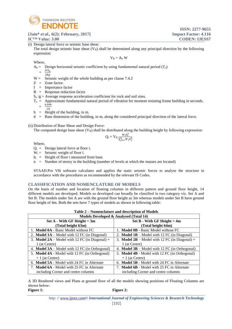
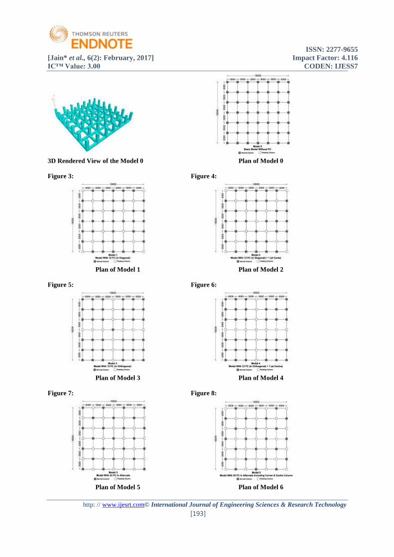
CLASSIFICATION AND NOMENCLATURE OF MODELS On the basis of number and location of floating columns in different pattern and ground floor height, 14
different models are developed. Models so developed can broadly be classified in two category viz. Set A and
Set B. The models under Set A are with the ground floor height as 3m whereas models under Set B have ground
floor height of 4m. Both the sets have 7 types of models as shown in following table:
Table 2 – Nomenclature and description of Models
Models Developed & Analysed (Total 14)
Set A - With GF Height = 3m
(Total height 63m)
Set B - With GF Height = 4m
(Total height 64m)
1. Model 0A - Basic Model without FC 1. Model 0B - Basic Model without FC
2. Model 1A – Model with 12 FC (in Diagonal) 2. Model 1B – Model with 12 FC (in Diagonal)
3. Model 2A – Model with 12 FC (in Diagonal) +
1 (at Centre)
3. Model 2B – Model with 12 FC (in Diagonal) +
1 (at Centre)
4. Model 3A – Model with 12 FC (in Orthogonal) 4. Model 3B – Model with 12 FC (in Orthogonal)
5. Model 4A - Model with 12 FC (in Orthogonal)
+ 1 (at Centre)
5. Model 4B - Model with 12 FC (in Orthogonal)
+ 1 (at Centre)
6. Model 5A - Model with 24 FC in Alternate 6. Model 5B - Model with 24 FC in Alternate
7. Model 6A - Model with 25 FC in Alternate
including Corner and centre columns
7. Model 6B - Model with 25 FC in Alternate
including Corner and centre columns
A 3D Rendered views and Plans at ground floor of all the models showing positions of Floating Columns are
shown below:
Figure 1: Figure 2:
ISSN: 2277-9655
[Jain* et al., 6(2): February, 2017] Impact Factor: 4.116
IC™ Value: 3.00 CODEN: IJESS7
http: // www.ijesrt.com© International Journal of Engineering Sciences & Research Technology
[193]
3D Rendered View of the Model 0 Plan of Model 0
Figure 3: Figure 4:
Plan of Model 1 Plan of Model 2
Figure 5: Figure 6:
Plan of Model 3 Plan of Model 4
Figure 7: Figure 8:
Plan of Model 5 Plan of Model 6
ISSN: 2277-9655
[Jain* et al., 6(2): February, 2017] Impact Factor: 4.116
IC™ Value: 3.00 CODEN: IJESS7
http: // www.ijesrt.com© International Journal of Engineering Sciences & Research Technology
[194]
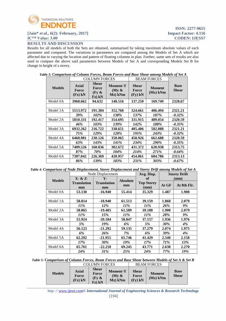
RESULTS AND DISCUSSION Results for all models of both the Sets are obtained, summarised by taking maximum absolute values of each
parameter and compared. The variations in parameters are compared among the Models of Set A which are
affected due to varying the location and pattern of floating columns in plan. Further, same sets of results are also
used to compare the above said parameters between Models of Set A and corresponding Models Set B for
change in height of a storey.
Table 3: Comparison of Column Forces, Beam Forces and Base Shear among Models of Set A
Models
COLUMN FORCES BEAM FORCES
Base
Shear
Axial
Force
(Fx) kN
Shear
Force
(Fy &
Fz) kN
Moment-Y
(My &
Mz) kNm
Shear
Force
(Fy) kN
Moment
(Mz) kNm
Model 0A 3968.662 94.632 148.516 137.250 169.749 2328.67
Model 1A 5513.972 191.384 352.768 324.661 486.494 2321.21
39% 102% 138% 137% 187% -0.32%
Model 2A 5810.331 192.417 354.695 331.915 489.054 2320.59
46% 103% 139% 142% 188% -0.35%
Model 3A 6932.262 216.722 338.651 405.406 582.088 2321.21
75% 129% 128% 195% 243% -0.32%
Model 4A 6468.981 230.126 358.065 458.926 662.688 2320.59
63% 143% 141% 234% 290% -0.35%
Model 5A 7409.526 160.836 302.672 431.372 628.938 2313.75
87% 70% 104% 214% 271% -0.64%
Model 6A 7387.042 226.369 420.957 454.861 684.786 2313.13
86% 139% 183% 231% 303% -0.67%
Table 4: Comparison of Node Displacement, Storey Displacement and Storey Drift among Models of Set A
Models
Node Displacement Avg. Disp.
of
Top Storey
(mm)
Storey Drift
(mm) X- & Z-
Translation
mm
Y-
Translation
mm
Absolute
mm At GF At 8th Flr.
Model 0A 53.130 -16.940 55.414 35.329 1.487 1.908
Model 1A 58.814 -18.940 61.513 39.159 1.868 2.079
11% 12% 11% 11% 26% 9%
Model 2A 58.865 -19.405 61.589 39.188 1.900 2.079
11% 15% 11% 11% 28% 9%
Model 3A 55.924 -20.184 58.847 37.157 1.936 1.976
5% 19% 6% 5% 30% 4%
Model 4A 56.123 -21.292 59.135 37.279 2.074 1.975
6% 26% 7% 6% 39% 4%
Model 5A 62.292 -21.955 65.746 41.429 2.540 2.158
17% 30% 19% 17% 71% 13%
Model 6A 65.761 -22.218 69.245 43.771 2.638 2.270
24% 31% 25% 24% 77% 19%
Table 5: Comparison of Column Forces, Beam Forces and Base Shear between Models of Set A & Set B
Models
COLUMN FORCES BEAM FORCES
Base
Shear
Axial
Force
(Fx) kN
Shear
Force
(Fy &
Fz) kN
Moment-Y
(My &
Mz) kNm
Shear
Force
(Fy) kN
Moment
(Mz) kNm
ISSN: 2277-9655
[Jain* et al., 6(2): February, 2017] Impact Factor: 4.116
IC™ Value: 3.00 CODEN: IJESS7
http: // www.ijesrt.com© International Journal of Engineering Sciences & Research Technology
[195]
Model 0A 3968.662 94.632 148.516 137.250 169.749 2328.67
Model 0B 3969.036 95.180 169.441 137.838 170.645 2338.83
0A v/s 0B 0.01% 0.58% 14.09% 0.43% 0.53% 0.44%
Model 1A 5513.972 191.384 352.768 324.661 486.494 2321.21
Model 1B 5507.512 189.356 348.906 321.585 476.902 2328.88
1A v/s 1B -0.12% -1.06% -1.09% -0.95% -1.97% 0.33%
Model 2A 5810.331 192.417 354.695 331.915 489.054 2320.59
Model 2B 5772.109 190.472 350.983 337.543 479.636 2328.05
2A v/s 2B -0.66% -1.01% -1.05% 1.70% -1.93% 0.32%
Model 3A 6932.262 216.722 338.651 405.406 582.088 2321.21
Model 3B 6845.789 222.922 345.334 405.576 577.430 2328.88
3A v/s 3B -1.25% 2.86% 1.97% 0.04% -0.80% 0.33%
Model 4A 6468.981 230.126 358.065 458.926 662.688 2320.59
Model 4B 6403.288 234.329 363.800 450.569 653.125 2328.05
4A v/s 4B -1.02% 1.83% 1.60% -1.82% -1.44% 0.32%
Model 5A 7409.526 160.836 302.672 431.372 628.938 2313.75
Model 5B 7394.347 166.938 349.125 435.203 655.274 2318.93
5A v/s 5B -0.20% 3.79% 15.35% 0.89% 4.19% 0.22%
Model 6A 7387.042 226.369 420.957 454.861 684.786 2313.13
Model 6B 7415.909 226.200 420.537 468.898 714.569 2318.11
6A v/s 6B 0.39% -0.07% -0.10% 3.09% 4.35% 0.22%
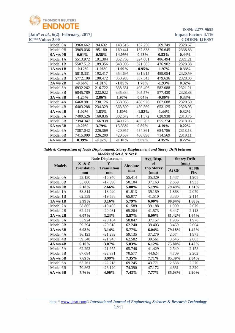
Table 6: Comparison of Node Displacement, Storey Displacement and Storey Drift between
Models of Set A & Set B
Models
Node Displacement Avg. Disp.
of
Top Storey
(mm)
Storey Drift
(mm) X- & Z-
Translation
mm
Y-
Translation
mm
Absolute
mm At GF At 8th
Flr.
Model 0A 53.130 -16.940 55.414 35.329 1.487 1.908
Model 0B 55.880 -17.390 58.184 37.163 2.669 1.933
0A v/s 0B 5.18% 2.66% 5.00% 5.19% 79.49% 1.31%
Model 1A 58.814 -18.940 61.513 39.159 1.868 2.079
Model 1B 62.339 -19.538 65.077 41.510 3.380 2.114
1A v/s 1B 5.99% 3.16% 5.79% 6.00% 80.94% 1.68%
Model 2A 58.865 -19.405 61.589 39.188 1.900 2.079
Model 2B 62.441 -20.031 65.204 41.573 3.447 2.113
2A v/s 2B 6.07% 3.23% 5.87% 6.09% 81.42% 1.64%
Model 3A 55.924 -20.184 58.847 37.157 1.936 1.976
Model 3B 59.294 -20.818 62.240 39.403 3.469 2.004
3A v/s 3B 6.03% 3.14% 5.77% 6.04% 79.18% 1.42%
Model 4A 56.123 -21.292 59.135 37.279 2.074 1.975
Model 4B 59.548 -21.945 62.582 39.561 3.646 2.003
4A v/s 4B 6.10% 3.07% 5.83% 6.12% 75.80% 1.42%
Model 5A 62.292 -21.955 65.746 41.429 2.540 2.158
Model 5B 67.084 -22.831 70.577 44.624 4.709 2.202
5A v/s 5B 7.69% 3.99% 7.35% 7.71% 85.39% 2.04%
Model 6A 65.761 -22.218 69.245 43.771 2.638 2.270
Model 6B 70.862 -23.120 74.390 47.172 4.881 2.320
6A v/s 6B 7.76% 4.06% 7.43% 7.77% 85.03% 2.20%
ISSN: 2277-9655
[Jain* et al., 6(2): February, 2017] Impact Factor: 4.116
IC™ Value: 3.00 CODEN: IJESS7
http: // www.ijesrt.com© International Journal of Engineering Sciences & Research Technology
[196]
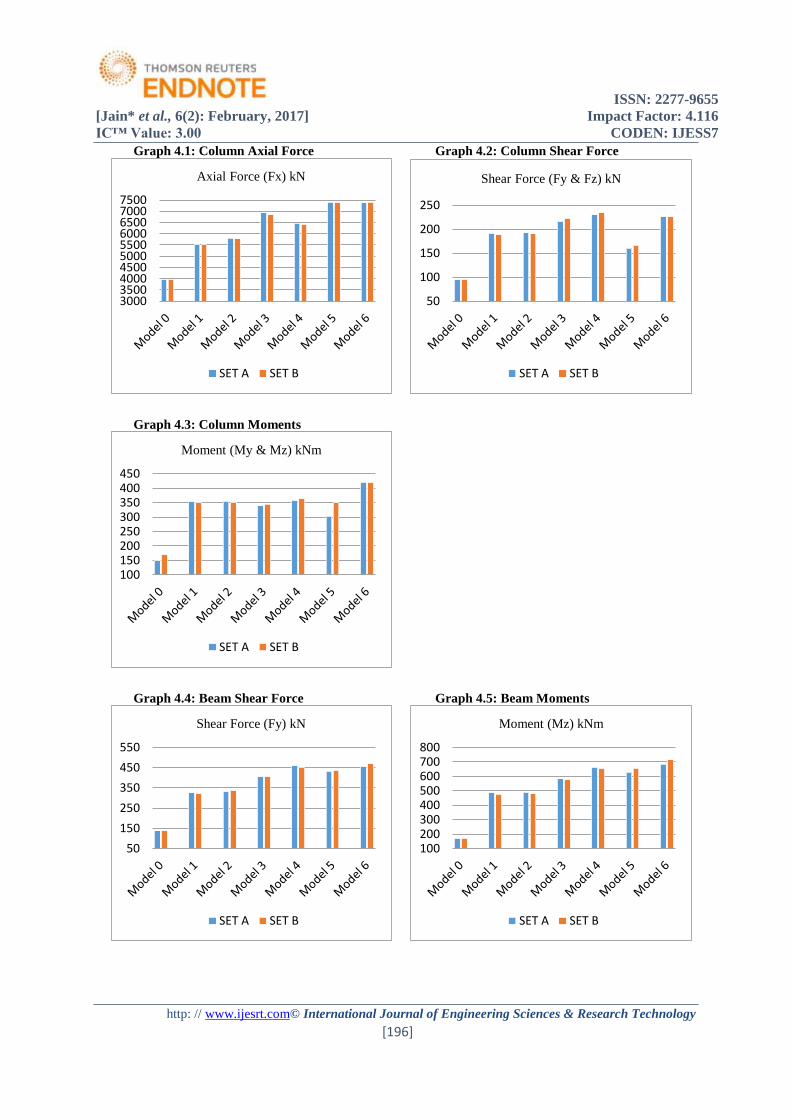
Graph 4.1: Column Axial Force Graph 4.2: Column Shear Force
Graph 4.3: Column Moments
Graph 4.4: Beam Shear Force Graph 4.5: Beam Moments
3000350040004500500055006000650070007500
Axial Force (Fx) kN
SET A SET B
50
100
150
200
250
Shear Force (Fy & Fz) kN
SET A SET B
100150200250300350400450
Moment (My & Mz) kNm
SET A SET B
50
150
250
350
450
550
Shear Force (Fy) kN
SET A SET B
100200300400500600700800
Moment (Mz) kNm
SET A SET B
ISSN: 2277-9655
[Jain* et al., 6(2): February, 2017] Impact Factor: 4.116
IC™ Value: 3.00 CODEN: IJESS7
http: // www.ijesrt.com© International Journal of Engineering Sciences & Research Technology
[197]
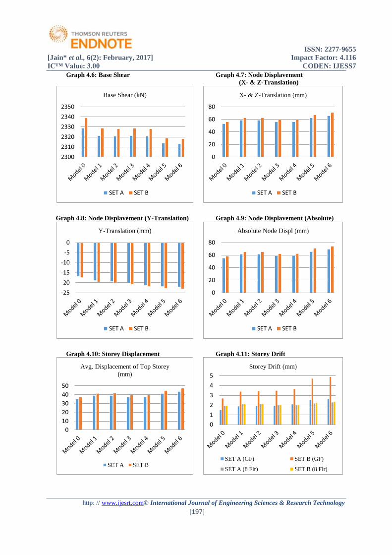
Graph 4.6: Base Shear Graph 4.7: Node Displavement
(X- & Z-Translation)
Graph 4.8: Node Displavement (Y-Translation) Graph 4.9: Node Displavement (Absolute)
Graph 4.10: Storey Displacement Graph 4.11: Storey Drift
2300
2310
2320
2330
2340
2350
Base Shear (kN)
SET A SET B
0
20
40
60
80
X- & Z-Translation (mm)
SET A SET B
-25
-20
-15
-10
-5
0
Y-Translation (mm)
SET A SET B
0
20
40
60
80
Absolute Node Displ (mm)
SET A SET B
0
10
20
30
40
50
Avg. Displacement of Top Storey
(mm)
SET A SET B
0
1
2
3
4
5
Storey Drift (mm)
SET A (GF) SET B (GF)
SET A (8 Flr) SET B (8 Flr)
ISSN: 2277-9655
[Jain* et al., 6(2): February, 2017] Impact Factor: 4.116
IC™ Value: 3.00 CODEN: IJESS7
http: // www.ijesrt.com© International Journal of Engineering Sciences & Research Technology
[198]
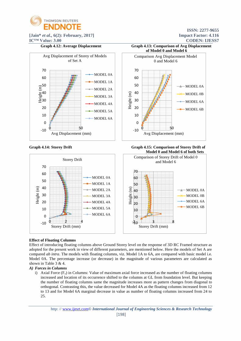
Graph 4.12: Average Displacement Graph 4.13: Comparison of Avg Displacement
of Model 0 and Model 6
Graph 4.14: Storey Drift Graph 4.15: Comparison of Storey Drift of
Model 0 and Model 6 of both Sets
Effect of Floating Columns
Effect of introducing floating columns above Ground Storey level on the response of 3D RC Framed structure as
adopted for the present work in view of different parameters, are mentioned below. Here the models of Set A are
compared ab intra. The models with floating columns, viz. Model 1A to 6A, are compared with basic model i.e.
Model 0A. The percentage increase (or decrease) in the magnitude of various parameters are calculated as
shown in Table 3 & 4.
A) Forces in Columns
i) Axial Force (Fx) in Columns: Value of maximum axial force increased as the number of floating columns
increased and location of its occurrence shifted to the columns at GL from foundation level. But keeping
the number of floating columns same the magnitude increases more as pattern changes from diagonal to
orthogonal. Contrasting this, the value decreased for Model 4A as the floating columns increased from 12
to 13 and for Model 6A marginal decrease in value as number of floating columns increased from 24 to
25.
-10
0
10
20
30
40
50
60
70
0 50
Hei
ght
(m)
Avg Displacement (mm)
Avg Displacement of Storey of Models
of Set A
MODEL 0A
MODEL 1A
MODEL 2A
MODEL 3A
MODEL 4A
MODEL 5A
MODEL 6A
-10
0
10
20
30
40
50
60
70
0 50H
eight
(m)
Avg Displacement (mm)
Comparison Avg Displacement Model
0 and Model 6
MODEL 0A
MODEL 0B
MODEL 6A
MODEL 6B
-10
0
10
20
30
40
50
60
70
0 2 4
Hei
ght
(m)
Storey Drift (mm)
Storey Drift
MODEL 0A
MODEL 1A
MODEL 2A
MODEL 3A
MODEL 4A
MODEL 5A
MODEL 6A
-10
0
10
20
30
40
50
60
70
-2 3 8
Hei
ght
(m)
Storey Drift (mm)
Comparison of Storey Drift of Model 0
and Model 6
MODEL 0A
MODEL 0B
MODEL 6A
MODEL 6B
ISSN: 2277-9655
[Jain* et al., 6(2): February, 2017] Impact Factor: 4.116
IC™ Value: 3.00 CODEN: IJESS7
http: // www.ijesrt.com© International Journal of Engineering Sciences & Research Technology
[199]
ii) Shear Forces (Fy & Fz) in Y- and Z-direction: Due to symmetry in plan and loading as well, the values of
shear forces in both directions are same for all the models. About 25% of the columns in diagonal pattern
are floated initially in model 1A and 2A, Shear forces increased by more than double (increased by
~100%) as compared with basic model. The models with orthogonal pattern show the higher values as
compare to diagonal pattern, though the numbers of floating columns are same. In both cases shear forces
increased further when central column is floated. Shear force in Model 5A (24 FC) is lowest, 1.7 times
(70% higher), among models with floating columns exceptionally. Maximum shear force magnitude in
Model 6A is almost equal to Model 4A, though it has double numbers of floating columns. For all the
models, location of maximum shear force are at I floor which is occurring at sixth floor in Model 0A.
iii) Moments (My & Mz) about Y- and Z-directions: Since structure is symmetric in geometry as well as
loading, the Moments about both the lateral axes are same. In models 1A to 4A with 12 (or 13) floating
columns, moment values increased by about 2.4 times (increased by about 140%) but remains 2 times
(104%) when 24 columns floated (Model 5A) and is about 2.8 times (183%) when 25 columns floated,
for Model 6A. Location of maximum moment is below GL in Model 0A and for rest of the models it
appears in columns at I floor except for Model 5A in which the location is ground floor.
B) Forces in Beams: i) Shear Forces (Fy & Fz) in Y- and Z-direction: Shear force in Z-direction (lateral) is much less and can be
ignored. Shear force in Y-direction increased to about 2.4 times when one-fourth columns are floated in
diagonal pattern (Model 1A & 2A). The Shear Force increased to 3 times when pattern changes to
orthogonal with same number of floating columns (Model 3A) and further increased to more than 3.3
when central column also floated. The value remains almost same as orthogonal pattern when 50%
columns are floated. The location of occurrence shifted to I floor from 7th floor.
ii) Moments (My & Mz) about Y- and Z-directions: Moment about Y-axis (vertical) is very very less (can be
seen in the tables) as compared to moment about Z-axis and hence, it is ignored. Moment about Z-axis
increased about 3 times when 25% floating columns are present in diagonal pattern but when patter
changes to orthogonal moment becomes 3.5 to 4 times i.e. increased by about 250-300%. Same is the
situation when floating columns increased to 50% (Model 5A & 6A). Location of occurrence of absolute
maximum moment shifted from top floor to 1st/Ground Floor.
C) Base Shear:
Base shear depends upon the Seismic weight of the whole building. When columns are floated without
changing the dimensions of other structural members, it obvious that the Seismic weight of the whole
building will be reduced, and hence the Base Shear. Results above also confirm the same. As the number of
floating columns increased, the magnitude of base shear decreased accordingly, though marginally.
D) Node Displacement: i) X- and Z-Translation: Since the model is about both the orthogonal axes the values of translations of
nodes in X- and Z- Direction are same. Results show that the maximum Translation is at top floor hence
only those values are compared. Translation increased by 11% when 25% floating columns are provided
in diagonal pattern but increased by only 5-6% when pattern is orthogonal. As the % of floating columns
increased to 50%, the value is also increased by 17% (Model5A) and by 24% (Model 6A).
ii) Y-Translation: When number and patter of floating columns changes according to Model 1A to 6A,
value of translation also gradually increased by 12% to 31%. Negative value indicates the downward
displacement of nodes.
iii) Absolute Translation: Translation increased by 11% when 25% floating columns are provided in
diagonal pattern but increased by only 6-7% when pattern is orthogonal. As the % of floating columns
increased to 50%, the value is also increased by 19% (Model5A) and by 25% (Model 6A).
E) Average Storey Displacement and Storey Drift:
The maximum value of Average Storey Displacement occurs at top storey only and varies in the same
pattern as X- (or Z-) Translation as above. Average Storey Displacement for full height of the building can
be observed in Graph 4.12.
Store Drift is compared at two levels viz. at Ground Floor Level and at 8th Floor Level as these levels are
found critical and comparable. The value of storey drift at 8th floor is higher than that at ground floor in
model without floating columns. These values increased when columns are floated. In Model 1A & 2A,
values increased by 26-28% and 9% respectively and in Model 3A, these values increased by 30% & 4%.
The value of drift at 8th floor for Models 1A & 2A remains larger than the value at ground floor and for
Model 3A value of drift at 8th floor is slightly higher than that at ground floor. But for rest of the models this
pattern is reversed i.e. the value of drift at ground floor exceeds the value at 8th floor. In Model4A drift
ISSN: 2277-9655
[Jain* et al., 6(2): February, 2017] Impact Factor: 4.116
IC™ Value: 3.00 CODEN: IJESS7
http: // www.ijesrt.com© International Journal of Engineering Sciences & Research Technology
[200]
increased by 39% at ground floor and by 4% at 8th floor and in Model 5A & 6A it increased by more than
70% at ground floor and 13% & 19% respectively at 8th floor. Notwithstanding this, the values of Storey
drift are within safe limit as prescribed by the IS codes. Storey Drift for full height of the building can be
observed in Graph 4.14.
Effect of variation in Floor Height
Effect of variation in floor height of Ground Storey can be understood by comparing various parameters
(absolute maximum values) of the models of Set B with that of Set A. The percentage increase (or decrease) in
the magnitude of various parameters of corresponding Models are calculated and tabulated in Table 5 & 6.
i) Column Forces, Beam Forces, Base Shear: It was observed that there is not much variation in maximum
absolute values of these parameters and also the location of occurrence also remains unchanged for
maximum parameters, so not discussed here.
ii) Node Displacement, Average Storey Displacement and Storey Drift: The values of Node displacement and
Average storey displacement of top floor increased by 5-8% for Set B Models as compared with Set A
Models and similarly the value of storey drift at 8th floor is marginally increased in the range of 1.3-2.2%.
But a significant variation is observed, increment by 80-85%, in the values of Storey Drift at ground floor
where floor height is increased by 1m and also the number of columns was reduced thereat. The variation in
Average Storey Displacement and Storey Drift for full height of the building can be seen in Graph No. 4.13
& 4.15 respectively.
CONCLUSION In the present work a comparative study is carried out on effect of provision of floating columns under seismic
conditions assuming zone IV. The study is based on response of an 3D RCC framed G+20 residential building
which is reflected through various parameters such as Axial Forces, Shear Forces & Moments in columns &
beams, Node Displacement, Storey Displacement and Storey Drift. Floating columns were introduced above
ground floor level in different positions and various patterns. The effect of variation in storey height was also
studied by varying the storey height of ground floor. All the models of were analysed with the help of
STAAD.Pro software and results were compared with the results of models without floating columns. Following
conclusions were drawn in light of above comparisons.
Building with uniform storey height
The values of all the parameters increase significantly with increase in number of floating columns except Base
Shear, which is getting reduced.
When one-fourth columns are required to be floated, the diagonal pattern is a better option as compared to the
orthogonal pattern from design point of view as the increment in governing forces is lesser in diagonal pattern.
But from displacement consideration orthogonal pattern proves to be better.
Location of Maximum Absolute Axial force in column shifted from foundation level to GF where lesser number
of columns is present whereas Shear Forces and Moment shifted to 1st floor from 6th floor and below ground
floor respectively.
Appearance of Maximum absolute of Fy & Mz in beams shifted from 7th floor as in normal building (one-third
height) to 1st floor (where floating columns started).
Maximum value of storey drift is observed at 8th floor level in building without floating columns and building
with one fourth floating columns whereas when floating columns increased, the maximum value found to be at
ground floor.
Building with increased storey height of Ground Floor
The maximum absolute value of parameters related to displacement not much increased (about 5-7%) but the
storey drift at ground floor is very much increased (about 80-85%). It can be concluded that the variation in
storey height should be avoided and if it is unavoidable, may be controlled by increasing the area of cross-
sections of columns thereat.
Variation in the value of various parameters related to forces in columns and beams are very marginal.
FUTURE SCOPE
The present research work is done by analysing the models of G+20 building, symmetrical in plan by equivalent
static method using STAAD.Pro V8i and compared on the basis of ten parameters. Research can be further
extended by keeping in view the following points:
a) Adopting Dynamic analysis method;
b) Assuming Unsymmetrical building;
c) Analysing taller structure;
ISSN: 2277-9655
[Jain* et al., 6(2): February, 2017] Impact Factor: 4.116
IC™ Value: 3.00 CODEN: IJESS7
http: // www.ijesrt.com© International Journal of Engineering Sciences & Research Technology
[201]
d) Using other tools for analysing such as ETABS, SAP, etc.
REFERENCES [1] Tanveer Asif Zerdi, Syed Aftab Hussain, Mohammed Ali, Mahreen Naaz Zerdi, Md. Haroon, Seismic
Analysis of RCC Building with and without floating columns using ETABS Software and its comparison
with Zone II to Zone V, Indian Journal of Research, Volume-5, Issue-5, pp - 179 & 180, May-2016.
[2] Sarika Yadav, Raksha Parolkar, Seismic Behaviour of Multi-storey buildings having Floating Columns,
International Journal of Civil and Structural Engineering Research, Volume-4, Issue-1, pp 87-94, April-
2016.
[3] Avinash Pardhi, Parakh Shah, et al, International Journal of Advanced Technology in Engineering and
Science, Volume-4, Issue-3, pp 615-621, March 2016.
[4] Gaurav Kumar, Megha Kalra, Review Paper on Seismic Analysis of RCC Frame Structures with Floating
Columns, International Journal of Advanced Technology in Engineering and Science, Volume-4, Special
Issue-01, pp 125-128, February 2016.
[5] T. Chandrshekhar, J. Vara Prasad, B. Sudharshan Reddy, Comparison of Seismic Analysis of a Floating
Column Building and a Normal Building using ETABS-2013, International Journal & Magzine of
Engineering, Technology, Management and Research, Volume-3, Issue-2, pp 1099-1110, February 2016.
[6] Ms. Priyanka D. Motghare, Numerical Studies of RCC Frame with different position of Floating Columns,
International Journal of Progresses in Engineering, Management, Science and Humanities, Volume-2,
Issue-1, 2016.
[7] Stella Evangeline, D. Satish, E. V. Raghava Rao, Pushover Analysis for RC building with and without
Floating Columns, International Journal of Advancement in Research & Technology, Volume-4, Issue-11,
pp 51-55, November 2015.
[8] Priyanka kumara, Dr. Mrs. N. R. Dhamge, Analysis of Multi-storey building with Floating Column,
International Journal for Scientific Research & Development, Volume-3, Issue-8, pp 398-401, 2015.
[9] Badgire Udhav S, Shaikh A. N., Maske Ravi G., Analysis of Multi-storey building with Floating Columns,
International Journal of Engineering Research, Volume-4, Issue-9, pp 475-478, September 2015.
[10] Kavya N., Dr. K. Manjunatha, Sachin P Dyappanavar, Seismic Evaluation of Multi-storey RC Building
with and without Floating Column, International Research Journal of Engineering and Technology,
Volume-2, Issue-6, pp 361-365, September 2015.
[11] Shivli Roy and Gargi Danda De, Comparative Studies of Floating Column of different Multi-storeyed
Building, International Journal for Research in Applied Science & Engineering Technology, Volume-3,
Issue-8, pp 474-482, August 2015.
[12] Sarita Singla and Ashfi Rahman, Effect of Floating Column on Seismic Response of Multi-storeyed RC
framed building, International Journal of Engineering Research and Technology, Volume-4, Issue-6, pp
1131-1136, June 2015
[13] Isha Rohilla, S.M. Gupta and Babita Saini, Seismic Response of Multi-storey Irregular Building with
Floating Column, International Journal of Research in Engineering and Technology, Volume-4, Issue-3, pp
506-518, March 2015.
[14] Sabri S. and Praveen J.V., Seismic Analysis of Multi-storey Building with Floating Column, International
Journal of Civil and Structural Engineering Research, Volume-2, Issue-2, pp 12-23, October 2014 – March
2015.
[15] Srikanth M.K. and Yogeendra R. Holebagilu, Seismic Response of Complex Buildings with Floating
Column for Zone II and Zone V, International Journal of Engineering Research, Volume-2, Issue-4, pp 1-
11, 2014.
[16] T. Raja Sekhar and P.V. Prasad, Study of Behaviour of Seismic Analysis of Multi Storied Building with
and without Floating Column, Caribbean Journal of Science and Technology, Volume-2, pp 697-710,
2014.
[17] A.P. Mundada and S.G. Sawdatkar, Comparative Seismic Analysis of Multi-storey Building with and
without Floating Column, International Journal of Current Engineering and Technology, Volume-4, Issue-
5, pp 3395-3400, October 2014.
[18] Sreekanth Gandla Nanabala, Pradeep Kumar Ramancharla, Arunakanthi E., Seismic Analysis of a Normal
Building and Floating Column Building, International Journal of Engineering Research and Technology,
Volume-3, Issue-9, pp 981-987, September 2014

ISSN: 2277-9655
[Jain* et al., 6(2): February, 2017] Impact Factor: 4.116
IC™ Value: 3.00 CODEN: IJESS7
http: // www.ijesrt.com© International Journal of Engineering Sciences & Research Technology
[202]
[19] Keerthi Gowda B.S. and Syed Tajoddeen, Seismic Analysis of Multi-storey Building with Floating
Columns, Proceedings of First Annual Conference on Innovations and Development in Civil Engineering,
ACIDIC-2014 NITK, Surathkal, India, pp 528-535, May 2014.
[20] Pratyush Malaviya, Saurav, Comparative Study of effect of Floating Columns on the Cost Analysis of a
Structure designed on STAAD Pro V8i, International Journal of Scientific & Engineering Research,
Volume-5, Issue-5, pp 22-34, May 2014.
[21] Prerna Nautiyal, Saleem Akhtar and Geeta Batham, Seismic Response Evaluation of RC Frame Building
with Floating Column considering different Soil Conditions, International Journal of Current Engineering
and Technology, Volume-4, Issue-1, pp 132-138, February 2014.
[22] IS Codes:
a) IS 456-2000 Plain & Reinforced Concrete – Code of Practice
b) IS 1893 (Part 1):2002, Indian Standard Criteria for Earthquakes Resistant of Design Structures.
c) IS 4326:1993, Indian Standard Code of practice for Earthquake Resistant Design and Construction of
Buildings.
d) IS 13827:1993, Indian Standard Guidelines for improving Earthquake Resistant of Earthen Buildings.
e) IS 13828:1993, Indian Standard Guidelines for improving Earthquake Resistant of Low Strength Masonry
Buildings.
f) IS 13920:1993, Indian Standard Code for practice for Ductile Detailing of Reinforced Concrete Structures
Subjected to Seismic Forces
[23] STAAD.Pro V8i – Software of Bentley Systems Inc. for Structural Analysis and Design.


![IJESRTijesrt.com/issues /Archives-2014/June-2014/76.pdf · http: // (C)International Journal of Engineering Sciences & Research Technology [492-506] alternative ingredient or material](https://img.pdfslide.us/doc/110x75/5e3d1d4cd064885c7d22e638/archives-2014june-201476pdf-http-cinternational-journal-of-engineering.jpg)


![IJESRTijesrt.com/issues /Archive-2018/July-2018/39.pdfOxygen (DO) value as well as strong color [9]. Biological, Physico-chemical and Biochemical plant are mainly used for textile](https://img.pdfslide.us/doc/110x75/607f71ea1c57ec386871a6ed/archive-2018july-201839pdf-oxygen-do-value-as-well-as-strong-color-9-biological.jpg)