Embed Size (px)
Citation preview

Architectures for Networks and Service
Semester I
I
master TSAC1 ARS
(Mixed version: English – Romanian)
E. Borcoci, UPB
2015-2016

TSAC 1- ARS-Sem I 2015-2016
TSAC1-ARS -E.Borcoci- UPB -2015-2016 2
Note : Acest curs este o continuare a cursurilor an IV sem I, II:
Communicatii de date
Arhitecturi si protocoale de comunicatie
Retele si Servcii
A se vedea si complementele din ANEXE

TSAC 1- ARS-Sem I 2015-2016
TSAC1-ARS -E.Borcoci- UPB -2015-2016 3
CONTENTS
1 MULTIPLE PLANES ARCHITECTURES 5
1.1 PRINCIPLES 5 1.2 SIGNALLING ISSUES 7
1.2.1 Example: QoS signaling 7 1.2.2 Example of out of band signalling: Session Initiation Protocol (SIP) 8 1.2.3 Standardization Effort in separation Data Plane-Control Plane 10
1.2.3.1 NSIS ( Next Step in Signalling) 10 1.2.3.2 IETF WG ForCES Forwarding and Control Element Seperaration, 2003 10
1.3 BUSINESS MODELS EXAMPLES 11 1.3.1 BM for Multimedia Communication Architectures 11
1.3.1.1 Customers and Users 11 1.3.1.2 Providers (PR) 11 1.3.1.3 Multiple Plane Architecture and Business Actors 13 1.3.1.4 Service Level Agreements/Specifications (SLA/SLS) 13
1.3.2 Novel BMs and actors (in the perspective of Future Internet) 14 1.3.2.1 Virtualisation-based systems 14 1.3.2.2 BM in Cloud Computing 15
1.4 EXAMPLES OF MULTIPLE PLANE ARCHITECTURES 17 1.4.1 IEEE 802.16 multi-plane stack ( lower layers) 17 1.4.2 Generic Example of a multi-plane architecture 19
1.4.2.1 An Architecture oriented to multimedia distribution 20 1.4.3 Next Generation Networks Architecture- high level view 21
1.4.3.1 Architectural layers: vertical and horizontal decomposition 22 1.4.3.1.1 Transport Stratum (TS) Functions 23 1.4.3.1.2 Service Stratum Functions 25 1.4.3.1.3 Management Functions 26 1.4.3.1.4 End-User Functions 27
1.5 SDN BASIC ARCHITECTURE 27 1.6 GENERAL LIST OF ACRONYMS 31

TSAC 1- ARS-Sem I 2015-2016
TSAC1-ARS -E.Borcoci- UPB -2015-2016 4
Table of Figures
Figure 1-1 Example of (ITU-T) Multiple Plane architecture- for QoS assurance.................................. 7
Figure 1-2 Diagram of a request, acceptance, setup and termination of a call....................................... 9
Figure 1-3 Basic SIP signaling configuration ..................................................................................... 10
Figure 1-4 Example of a generic multiple plane architecture ............................................................... 13
Figure 1-5 Generic IP Business Model (I) - and business relationships (SLA) ................................... 14
Figure 1-6 Example: IP Business Models (II) - Hub model and Cascade model................................. 14
Figure 1-7 Cloud access overview ....................................................................................................... 15
Figure 1-8 The NIST Conceptual Reference Model ............................................................................. 16
Figure 1-9 Interactions between the Actors in Cloud Computing (NIST) ............................................ 17
Figure 1-10 Basic IEEE 802.16 multi-plane protocol stack.................................................................. 18
Figure 1-11 (IEEE 802.16g-05/008r2, December 2005)...................................................................... 18
Figure 1-12 Relation IEEE802.16 vs. WiMAX Forum NWG ............................................................. 19
Figure 1-13 Generic example of a multi-plane architecture................................................................ 19
Figure 1-14 Business actors and multi-domain infrastructure............................................................... 20
Figure 1-15 QoS assurance methods in ENTHRONE architecture...................................................... 21
Figure 1-16 NGN Architecture.............................................................................................................. 22
Figure 1-17 NGN layered architecture [4] ........................................................................................... 23
Figure 1-18 NGN Functional Architecture [4]...................................................................................... 24
Figure 1-19 Layered Architectural Management Model and Function Areas (FCAPS)....................... 27
Figure 1-20 SDN generic architectture.................................................................................................. 28
TSAC 1- ARS-Sem I 2015-2016
TSAC1-ARS -E.Borcoci- UPB -2015-2016 5
1 MULTIPLE PLANES ARCHITECTURES
(English)
1.1 Principles
Ongoing standardization : IETF, ITU-T , ETSI, IEEE, 3GPP
• Telecom originated layered architectures: more than one architectural plane
• IETF (TCP/IP- Internet) stack – originally only one plane
o (data + control + management)
Nowadays- recognized the need of defining several cooperating architectural planes
Reasons: Real systems/networks deals with:
- user data flow transfer
- network resources ( paths, links, buffers, etc. ) should be controlled
- short time scale, long time scale
- high level services should be controlled (short and long time scale)
Architectural Planes
• Data plane ( DPl)- transport of user data traffic directly:
o Examples of functions:
� Main traditional function
• Forwarding
� QoS – related (transfer the user data flows and accomplish the traffic control
mechanisms to assure the desired level of QoS)
• traffic classification,
• packet marking
• traffic policing (reactive action)
• traffic shaping
• queuing and scheduling
� buffer management
� congestion avoidance
• Control plane (CPl)
o controls the pathways for user data traffic
o short term actions for resource and traffic engineering and control, including routing.
o Examples
� Main traditional function
• Routing ( routes computation, intra and inter-domains)
� Traffic Engineering and QoS – related
• Admission control (preventive action)

TSAC 1- ARS-Sem I 2015-2016
TSAC1-ARS -E.Borcoci- UPB -2015-2016 6
• Resource reservation.
o In multi-domain environment the MPl and also CPl are logically divided in two sub-
planes: inter-domain and intra-domain. This approach allows each domain to have its
own management and control policies and mechanisms.
• Management plane (MPl)
o the operation, administration, and management aspects of the resources and services
to serve user data traffic
o long term actions related to resource and traffic management in order to assure the
desired QoS levels for the users and also efficient utilization of the network resources
o Examples of finctions:
� Monitoring ( hierarchical, i.e. on several levels)
� Management Policies (management based not on fixed configuration of
network elements but on set of rules),
� Service Management,
� Service and network restoration.
• Summary examples of multiple plane architectures (DPl + CPl + MPl):
• (early) Circuit switching-based systems: (2G)GSM, old- telecom arch. ISDN , BISDN
� reason: telecom design philosophy (user data have been seen long time ago -
from the beginning of telecom systems as separate entities from signalling and
management) data
� User(Data) plane, Control Plane, Mgmt Plane.
• (more recent )Packet-switching based – systems : TCP/IP
� Currently the arch. becomes multi-plane (DPl + CPl + MPl)
• IEEE 802.16 ( WiMAX),
• 3G, 4G (LTE, LTE-A), 5G
• Newest: Software Defined Networking (SDN)
o Clear separation ( including physical) :
� Data plane (forwarding)- contains Forwading
Elements ( FE)
� Control plane - contains centralised Controllers

TSAC 1- ARS-Sem I 2015-2016
TSAC1-ARS -E.Borcoci- UPB -2015-2016 7
Figure 1-1 Example of (ITU-T) Multiple Plane architecture- for QoS assurance
1.2 Signalling Issues
Signaling = actions performed in the control plane :
- convey application (or network) performance requirements
- reserve network resources across the network
- discover routes
- general control messages
- QoS related signalling
1.2.1 Example: QoS signaling
In band
- signalling info is part of the associated data traffic( typically presented in a particular header field
of the data packets. –(e.g., the TOS field in IPv4 as in DiffServ and 802.1p)
- Performed in the data plane ⇒ neither introduces additional traffic into the network nor incurs setup
delay for the data traffic.
- not suitable for resource reservation or QoS routing, which needs to be done a priori before data
transmission
- in-band signaling by definition is path-coupled (signaling nodes must be collocated with routers)
Out of band
- signalling info - carried by dedicated packets, separate from the associated data traffic. - introduces

TSAC 1- ARS-Sem I 2015-2016
TSAC1-ARS -E.Borcoci- UPB -2015-2016 8
extra traffic into the network and incurs an overhead for delivering desired network performance
it entails the use of a signaling protocol and further processing above the network layer, which tends
to render slower responses than in-band signaling.
- lends itself naturally to resource reservation or QoS routing.
- depending on whether the signaling path is closely tied to the associated data path, signaling is path-
coupled or decoupled
Path-coupled
- signaling nodes must be collocated with routers
signaling messages - routed only through the nodes that are potentially on the data path.
- advantage of reduced overall signaling processing cost (since it leverages network- layer routing
tasks)
- disadvantage of inflexibility in upgrading routers or in integrating control entities (e.g., policy
servers) not on the data path (or nontraditional routing methods)
If a path-coupled mechanism involves a signaling protocol, routers need to support the protocol and
be able to process related signaling messages
- Example of a path-coupled signaling protocol : RSVP
Path-decoupled
- signaling messages are routed through nodes that are not assumed to be on the data path
only out-of-band signaling may be path-decoupled. (to date, most out-of-band QoS signaling schemes
are path coupled.)
- signaling nodes should be dedicated and separate from routers
- advantage of flexibility in deploying and upgrading signaling nodes independent of routers or in
integrating control entities not on the data path
- disadvantage of added complexity and cost in overall processing and operational tasks.
Example: Session Initiation Protocol for VoIP, videoconference, etc.
1.2.2 Example of out of band signalling: Session Initiation Protocol (SIP)
• SIP (Session Initiation Protocol) is a signaling protocol, widely used for setting up,
connecting and disconnecting communication sessions, typically voice or video calls over
the Internet.
• SIP is a standardized protocol with its basis coming from the IP community and in most cases
uses UDP or TCP.
• The protocol can be used for setting up, modifying and terminating two-party (unicast), or
multiparty (multicast) sessions consisting of one or more media streams. Modifications can
include changing IP addresses or/or ports, inviting more participants, and adding or deleting
the media streams.
SIP is an application layer control protocol that supports five parts of making and stopping communications.

TSAC 1- ARS-Sem I 2015-2016
TSAC1-ARS -E.Borcoci- UPB -2015-2016 9
It does not provide services, therefore it acts with other protocols to provide these services, one of
which is typically RTP that carries the voice for a call. The five parts of setting up and terminating
calls that SIP handles are:
• User Location: Determines where the end system is that will be used for a call.
• User Availability: Determination of the willingness (availability) of the called party to engage
in a call.
• User Capabilities: Determination of the media and parameters which will be used for the call.
• Session Setup: Establishment of the session parameters from both parties (ringing).
• Session Management: Invoking the services including transfer, termination, and modifying
the sessions parameters.
SIP has a request/response transaction model
- each transaction consists of a request that invokes a particular method or function on
the server and at least one response.
Figure 1-2 Diagram of a request, acceptance, setup and termination of a call.
Note: the media flow – voice packets- do not circulate on the same path as SIP messages, but the path
is selected by the routing function of the network.

TSAC 1- ARS-Sem I 2015-2016
TSAC1-ARS -E.Borcoci- UPB -2015-2016 10
Figure 1-3 Basic SIP signaling configuration
1.2.3 Standardization Effort in separation Data Plane-Control Plane
1.2.3.1 NSIS ( Next Step in Signalling)
- Standards efforts underway specifically dealing with QoS signaling- e.g. IETF nsis working group
- developing a flexible signaling framework with path-coupled QoS signaling as its initial major
application
- a QoS signaling protocol defined under the framework - expected to address the limitations of RSVP
On path-decoupled signaling there seems not enough support in the IETF for a new project after
some explorative discussion
1.2.3.2 IETF WG ForCES Forwarding and Control Element Seperaration, 2003
� A. Doria, et al., Forwarding and Control Element Separation (ForCES) Protocol
Specification. RFC 5810 (Proposed Standard), Mar. 2010
� A parallel approach to SDN
� some common goals with SDN and Open Networking Foundation (ONF)
� Differences:
� ForCES: the internal network device architecture is redefined as the control
element separated from the forwarding element, but the combined entity is
still represented as a single network element to the outside world
• Aim: to combine new forwarding hardware with third-party control
within a single network device where the separation is kept within
close proximity (e.g., same box or room)
� SDN: Contrl Plane (CPl) is totally moved from net device
� FORCES published documents on : arch. framework, interactions, modelling
language, forwarding element (FE) functions, protocol between Ctrl and FE

TSAC 1- ARS-Sem I 2015-2016
TSAC1-ARS -E.Borcoci- UPB -2015-2016 11
1.3 Business Models Examples
Business Model = Set of actors having different roles (technical and/or organizational) in a complex
multi-actor system (offering connectivity services and high level services)
BM determine essentially the architecture of such a system
Note: to not confound this BM with a BM related to pure economic issues.
1.3.1 BM for Multimedia Communication Architectures
1.3.1.1 Customers and Users
• Customer (CST) (may be a “subscriber”) :
- entity, having legal ability to subscribe to QoS-based services offered by Providers
(PR) or Resellers (RS)
- target recipients of QoS-based services: CST/PR or CST/RS interaction
- Examples of CS: Householders, SMEs, large corporations, universities or public
organisations
• Service Level Agreements (SLA)- concluded between CS and providers
CST differentiation by : size , type of business, type of services required
• User (US)
- entity (human or process) - named by a CST and appropriately identified by PR for
actually requesting/accessing and using the QoS-based services cf. SLAs
- USs are end-users of the services, they can only exist in association with a CST
- may be associated with one or several CST using services according to the agreed
SLAs of the respective CST. (e.g. Company = Customer, End User = employee)
Note: In the current public internet, the majority of users are “subscribers” for Connectivity services
and maybe for a subset of high level services (e.g e-mail)
- frequently there is no SLA concluded for high level services quality; e.g for media
A/V streaming, IPTV, etc.
- best effort access to high level services is practised but with no guarantees
1.3.1.2 Providers (PR)
PR types :
• (High Level) Service Providers (SP)
• IP Network Providers (NP)
• Physical Connectivity Providers (PHYP) (or PHY infrastructure Providers)
• Resellers (RS)
• Content Providers (CP)
Network Providers (NPs)
- offer QoS-based plain IP connectivity services
- own and administer an IP network infrastructure
- may interact with Access Network Providers' (ANP) or CS can be connected directly
to NPs
- Expanding the geographical span of NPs
- Interconnected NPs - corresponding peering agreements
- IP NPs differentiation: small ( e.g. for a city) , medium (region) and large ( e.g.
continental)
(High Level) Service Providers (HLSP or SPs)
- offer higher-level (possible QoS-based) services e.g. : e-mail, VoIP, VoD, IPTV,
A/VC, etc.
- owns or not an IP network infrastructure

TSAC 1- ARS-Sem I 2015-2016
TSAC1-ARS -E.Borcoci- UPB -2015-2016 12
- administer a logical infrastructure to provision services (e.g. VoIP gateways, IP
videoservers, content distribution servers)
- may rely on the connectivity services offered by NPs (SPs Providers' interact with
NPs following a customer-provider paradigm based on SLAs
- expanding the geographical scope and augmenting the portfolio of the services
offered ⇒ SP may interact with each other
- size : small, medium and large
Physical Connectivity Providers (PHYP)
- offer physical connectivity services between determined locations
- services may also be offered in higher layers (layer-3 e.g. IP), (but only between
specific points)
- distinguished by their target market:
• Facilities (Infrastructure) Providers (FP)
• Access Network Providers (ANP) (could be seen as distinct stakeholders)
FPs services - are mainly offered to IP NPs (link-layer connectivity, interconnect with their peers
FPs differentiation : size of technology deployment means
ANPs - connect CST premises equipment to the SPs or NPs equipment
- own and administer appropriate infrastructure
- may be differentiated by
- technology (e.g. POTS, FR, ISDN, xDSL, WLAN, Ethernet, WiMAX, hybrid)
- their deployment means and their size
- may not be present as a distinct stakeholder in the chain of QoS-service delivery
- may be distinct administrative domains, interacting at a business level with SPs /NPs and/or
CSTs
Interactions between Providers
- mainly governed by the legislations of the established legal telecom regulation framework
- may follow a customer-provider and/or a consumer-producer paradigm on the basis of
SLAs
Reseller (RS)
- intermediaries in offering the QoS-based services of the PRs to the CSTs
- offer market-penetration services (e.g. sales force, distribution/selling points) to PRs for
promoting and selling their QoS-based services in the market
- may promote the QoS-based services of the PRs either 'as they are' or with 'value-added',
however adhering to the SLAs of the services as required by the 'Providers'
- interact with :
• CSTs on a customer-provider paradigm (SLA based)
• PRs based upon respective commercial agreements..
Different types RSs:
- according to whether they introduce value-added or not
- their market penetration means
- size ( # of of points of presence and/or sales force)
RSs examples: Dealers, electronic/computers commercial chains, service portals
Content Provider (CP)
- an entity (organisation) gathering/creating, maintain, and distributing digital
information.
- owns/operates hosts = source of downloadable content

TSAC 1- ARS-Sem I 2015-2016
TSAC1-ARS -E.Borcoci- UPB -2015-2016 13
- might not own any networking infrastructure to deliver the content
- content is offered to the customers or service providers.
- can contain : Content Manager(CM); several Content Servers (CS
1.3.1.3 Multiple Plane Architecture and Business Actors
Service Plane
Control Plane
Management Plane
Data Plane
CC ANP CP/CS SP NP
Inter-domain
manager
Figure 1-4 Example of a generic multiple plane architecture
• “Business” Actors
High Level - Service Providers (SP)
Content Providers (CP) ( can own separate Content Servers- CS)
Connectivity Services - Network Providers (NP)
Content Consumers (CC)
Access Services - Network Providers (AC)
• Any actor might have one or several functionalities depenfing on its role in the overall
architecture.
1.3.1.4 Service Level Agreements/Specifications (SLA/SLS)
SLA
• it is a contract : documented result of a negotiation between a customer and a provider
of a service that specifies the levels of availability, serviceability, performance,
operation or other attributes of the transport service
• SLA contains technical and non-technical terms and conditions
• May be established offline or online (using negotiation oriented-protocols)
Service Level Specification (SLS)
• It is a part of SLA
• SLS = set of technical parameters and their values, defining the service, offered by the provbider
to the customer
o e.g. service offered to a traffic stream by a network domain (e.g. Diffserv domain)

TSAC 1- ARS-Sem I 2015-2016
TSAC1-ARS -E.Borcoci- UPB -2015-2016 14
(HIGH LEVEL)
SERVICE
PROVIDER 1
USER
RESELLER
CUSTOM ER IP NETWORK
PROVIDER 1
PHYSICAL
CONNECTIVITY
PROVIDER 1
PROVIDER/
OPERATOR 1
HIGH LEVEL
SERVICE
PROVIDER N
IP NETWORK
PROVIDER M
PHYSICAL
CONNECTIVITY
PROVIDER P
. . . . .
May be joined
within the same
entity
. . . . .
. . . . .
Content
Provider
USER
USER
Figure 1-5 Generic IP Business Model (I) - and business relationships (SLA)
SERVICE
PROVIDER
USER
CUSTOM ER
CO NTENT
PRO VIDER
CO NTENT
M ANAGER
CO NTENT
SERVER
IP NETW ORK
PRO VIDER N
PRO VIDER
1
3.n 3.2 3.1
2
5
6 IP NETW ORK
PRO VIDER N
PH YSICAL
CONNECTIVITY
PROVIDER
PROVIDER
PHYSICA L
CO NNECTIVITY
PRO VIDER
Data
4. Data pipe QoS guaranteed
established through actions 3.x
…
…
3.1
3.2 3.n
Cascade model
Hub model
Figure 1-6 Example: IP Business Models (II) - Hub model and Cascade model
1.3.2 Novel BMs and actors (in the perspective of Future Internet)
1.3.2.1 Virtualisation-based systems
Virtual Network Provider (VNP)

TSAC 1- ARS-Sem I 2015-2016
TSAC1-ARS -E.Borcoci- UPB -2015-2016 15
- composes and configures and offer Virtual Network slices, i.e., a set of virtual
resources at request of higher layers, as a consequence of its provisioning policy or
during self-healing operations
- this approach avoids for the higher layers to establish direct relationships with
infrastructure providers and to take care of inter-domain connections at physical
layer.
Virtual Network Operator (VNO)
- manages and exploits the VNEt s provided by VNPs , on behalf of HLSPs or end
users
Note: the same organisational entity migh play the both roles :VNP and VNO
1.3.2.2 BM in Cloud Computing
CC: a model for enabling ubiquitous, convenient, on-demand network access
• to a shared pool of configurable computing resources (e.g., networks, servers, storage,
applications, and services)
• that can be rapidly provisioned and released with minimal management effort or service
provider interaction.
Figure 1-7 Cloud access overview
The cloud model defined by NIST: National Institute of Standards and Technology USA, is
composed of • five essential characteristics
• three service models
• four deployment models.
Basic Characteristics
• On-demand self-service ( “pay as you go” concept)
• Broad network access
• Resource pooling
• Rapid elasticity.
• Measured service.
Service Models
Software as a Service (SaaS): consumer can use the provider’s applications running on a cloud
infrastructure

TSAC 1- ARS-Sem I 2015-2016
TSAC1-ARS -E.Borcoci- UPB -2015-2016 16
Platform as a Service (PaaS): consumer can deploy onto the cloud infrastructure consumer-
created or acquired applications created using programming languages, libraries, services, and tools supported by the provider.
Infrastructure as a Service (IaaS): consumer can provision processing, storage, networks, and
other fundamental computing resources.
Extensions ( ITU-T) : Network as a Service – NaaS; Communication as a Service- CaaS, etc.
Note These notions have been generalised : XaaS ( Everything as a Service)
Deployment Models
Private cloud; Community cloud; Public cloud; Hybrid cloud
The NIST Conceptual Reference Model
NIST cloud computing reference architecture identifies the major actors, their activities and
functions in cloud computing.
The diagram depicts a generic high-level architecture and is intended to facilitate
- the understanding of the requirements,
- uses,
- characteristics and
- standards of cloud computing.
Five major actors: cloud consumer(ClCs), cloud provider(ClP), cloud carrier(ClCr), cloud auditor
(ClA) and cloud broker(ClBr). Each actor is an entity (a person or an organization) that participates in a transaction or process and/or
performs tasks in cloud computing (Table 1).
Figure 1-8 The NIST Conceptual Reference Model
Cloud Business Model ( NIST)
Actor Definition
Cloud Consumer (ClC) A person or organization that maintains a business relationship with, and
uses service from, Cloud Providers.

TSAC 1- ARS-Sem I 2015-2016
TSAC1-ARS -E.Borcoci- UPB -2015-2016 17
Cloud Provider (ClP) A person, organization, or entity responsible for making a service
available to interested parties.
Cloud Auditor (ClA) A party that can conduct independent assessment of cloud services,
information system operations, performance and security of the cloud
implementation.
Cloud Broker (ClB) An entity that manages the use, performance and delivery of cloud
services, and negotiates relationships between Cloud Providers and Cloud
Consumers.
Cloud Carrier ( ClCr) An intermediary that provides connectivity and transport of cloud services
from Cloud Providers to Cloud Consumers.
Example of interactions among the actors A cloud consumer may request cloud services from a cloud provider directly or via a cloud
broker. - A cloud auditor conducts independent audits and may contact the others to collect necessary
information.
Figure 1-9 Interactions between the Actors in Cloud Computing (NIST)
Service Level Agreements
• ClCs need SLAs to specify the technical performance requirements fulfilled by a cloud
provider.
• SLAs : quality of service, security, remedies for performance failures.
• A ClP may also list in the SLAs a set of promises explicitly not made to consumers, i.e.
limitations, and obligations that ClCs must accept.
• A cloud consumer can freely choose a ClP with better pricing and more favorable terms
• Typically a ClP’s pricing policy and SLAs are non-negotiable, unless the customer expects
heavy usage and might be able to negotiate for better contracts.
Depending on the services, activities and usage scenarios can be different among cloud consumers.
1.4 Examples of Multiple Plane Architectures
1.4.1 IEEE 802.16 multi-plane stack ( lower layers)
IEEE 802.16 : PHY + MAC
Multiple plane architecture: Data Plane(DPl), Control Plane (CPl), Management Plane (MPl)

TSAC 1- ARS-Sem I 2015-2016
TSAC1-ARS -E.Borcoci- UPB -2015-2016 18
Figure 1-10 Basic IEEE 802.16 multi-plane protocol stack
Figure 1-11 (IEEE 802.16g-05/008r2, December 2005)

TSAC 1- ARS-Sem I 2015-2016
TSAC1-ARS -E.Borcoci- UPB -2015-2016 19
Figure 1-12 Relation IEEE802.16 vs. WiMAX Forum NWG
1.4.2 Generic Example of a multi-plane architecture
Stra
tum
: Ap
plic
atio
n
An
d S
erv
ice
s S
tratu
m: T
ran
sp
ort
Da
ta P
lan
e
Application
Application
Data flow-user
Inter-domain
Resources and traffic Mng. Access & “Core”
Intra-domain Resources and traffic Mng.
Access & “Core”
Services and session Control
Co
ntro
l Pla
n
Control Resurse
Inter & Intra domain
Service Mng. (Planning provisioning,
Offering, monitoring)
Ma
na
ge
me
nt P
lan
e
Control flow
Figure 1-13 Generic example of a multi-plane architecture

TSAC 1- ARS-Sem I 2015-2016
TSAC1-ARS -E.Borcoci- UPB -2015-2016 20
1.4.2.1 An Architecture oriented to multimedia distribution
Example: Enthrone” European FP6 research 2006-2008 project
“End-to-End QoS through Integrated Management of Content, Networks and Terminals”
Business Actors: Includes the complex business model: CP, SP, CC, NP, ANP
• CC- Content consumer (Company, End users)
o Customer ( org), End user
• CP- Content Provider
o CPM content provider manager
o CS1, CS2, - Content Servers
• SP- Service Provider (high level services)
• NP- Network Provider (connectivity services)
• ANP – Access Network Providers
NP3
SM&RM
Content
Provider
Content
Server
Service
Provider
NP1
SM&RM NP2
SM&RM
Content
Consumers
SM&RM = Service Mgmt and
Resource Mgmt
Figure 1-14 Business actors and multi-domain infrastructure
General objectives:
• to Offer high level services: Video on Demand (VoD), Streaming, E-learning, Multimedia
distribution, IPTV (basically uni-directional)
• over heterogeneous network technology and Over multiple independent domains
• to manage, in an integrated way the whole chain of protected content handling transport and
delivery to user terminals across heterogeneous networks, while offering QoS-enabled
services
o methods of QoS control:
� provisioning (offline and online)
� adaptation of flows to network capabilities

TSAC 1- ARS-Sem I 2015-2016
TSAC1-ARS -E.Borcoci- UPB -2015-2016 21
NP1
ENTHRONE
NP2
AN
Content
Consumers
Content
Provider QoS quasi-static resource provisioning
QoS dynamic adaptation loop
Figure 1-15 QoS assurance methods in ENTHRONE architecture
Multiple plane architecture:
• DPl, CPl, MPl
• NGN like prinnciples: separation of transport and services
• Creation of an service overlay over IP networks
1.4.3 Next Generation Networks Architecture- high level view
• Standardization Players
• ATIS NGN FG: Alliance for Telecommunication Industry Solutions, Next Generation Networks
Focus Group - USA
• ITU-T NGN FG: International Telecommunication Union (Telecom), Next Generation Networks
Focus Group
• ETSI TISPAN: European Telecommunications Standards Institute, Telecoms & Internet
converged Services & Protocols for Advanced Networks
• 3GPP: Third Generation Partnership – standardization in Mobile 3G networks
NGN
• packet-based network
• able to provide Telecommunication multiple services
• able to make use of multiple broadband,
• QoS-enabled transport technologies
• service-related functions are independent from underlying transport-related technologies.
• enables unfettered access for users to networks and to competing service providers and/or services
of their choice.
• supports generalized mobility which will allow consistent and ubiquitous provision of services to
users.
Key requirements of an NGN Architecture
• Trust: Operator should be able to trust the network. User should be able to trust the operator
• Reliability: Users should find it reliable
• Availability: Network should always be available
• Quality: Able to control Quality of the Service
• Accountability: Determine usage of the Service

TSAC 1- ARS-Sem I 2015-2016
TSAC1-ARS -E.Borcoci- UPB -2015-2016 22
• Legal: Comply with laws in the local jurisdictions
• Generalized Mobility support
Note: Classical Internet cannot respond in very controllable manner to the above requirements
NGN characteristics
NGN: new telecommunications network for broadband fixed access
• facilitates convergence of networks and services
• enables different business models across access, core network and service domains
• it is an IP based network
• IETF Session Initiation Protocol (SIP) will be used for call & session control
•3GPP release 6 (2004) IMS will be the base for NGN IP Multimedia Subsystem
• enables any IP access to Operator IMS; from
Mobile domain
Home domain
Enterprise domain
• enables service mobility
• enables interworking towards circuit switched networks
• maintains Service Operator control for IMS signaling & media traffic
Transport Level
Applications and
Service Level
Management Plane
User (Data)
Plane
Control Plane
INTERNET
SCN
Figure 1-16 NGN Architecture
1.4.3.1 Architectural layers: vertical and horizontal decomposition

TSAC 1- ARS-Sem I 2015-2016
TSAC1-ARS -E.Borcoci- UPB -2015-2016 23
Figure 1-17 NGN layered architecture [4]
� The NGN functions are divided into service and transport strata according to
Recommendation Y.2011.
� End-user functions are connected to the NGN by the user-to-network interface (UNI),
� Other networks are interconnected through the network-to-network interface (NNI).
• Clear identification of the UNI and NNI is important to accommodate a wide
variety of off-the-shelf customer equipment while maintaining business boundaries
and demarcation points in the NGN environment.
� The application-to-network interface (ANI) forms a boundary with respect to third-party
application providers.
�
1.4.3.1.1 Transport Stratum (TS) Functions
• provide connectivity for all components and physically separated functions within the
NGN.
• IP – is the transport technology for NGN.
• provides IP connectivity for both EU equipment outside the NGN, and controllers and
enablers that usually reside on servers inside the NGN.
• provides end-to-end QoS, (desirable NGN feature)
• TS is divided into access networks and the core network, with a function linking the two
portions.
Access Functions
- manages end-user access to the network
- access-technology-dependent ( W-CDMA, xDSL, Cable access, Ethernet, optical, etc.)
TSAC 1- ARS-Sem I 2015-2016
TSAC1-ARS -E.Borcoci- UPB -2015-2016 24
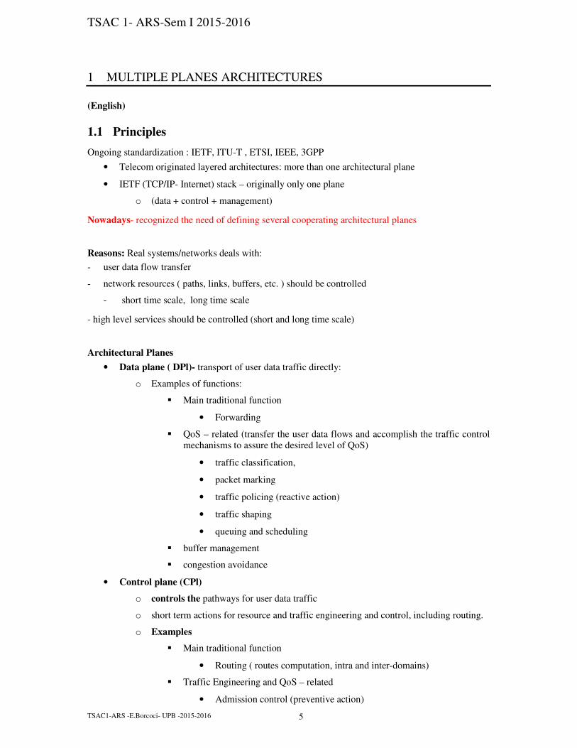
Figure 1-18 NGN Functional Architecture [4]
Access Transport Functions(Data Plane)
- transports information across the access network.
- provide QoS control mechanisms dealing directly with user traffic: buffer management,
queuing and scheduling, packet filtering, traffic classification, marking, policing, and shaping.
Edge Functions —used for traffic processing when access traffic is merged into the core network.
Core Transport Functions (Data Plane) - information transport throughout the core network.
- differentiate the quality of transport in the network, according to interactions with the
transport control functions.
- provide QoS mechanisms dealing directly with user traffic: buffer management, queuing
and scheduling, packet filtering, traffic classification, marking, policing and shaping, gate control, and
firewalls.
Network Attachment Control Functions (NACF)
- provide registration at the access level and initialization of end-user functions for accessing
NGN services.
- provide network-level identification/authentication
- manage the IP address space of the access network, and authenticate access sessions
- announce the contact point of the NGN service and application functions to the end user.
-i.e. NACF assist end-user equipment in registering and starting use of the NGN.

TSAC 1- ARS-Sem I 2015-2016
TSAC1-ARS -E.Borcoci- UPB -2015-2016 25
Resource and Admission Control Functions (RACF)
- provide AC and gate control functionalities, including control of network address and port
translation (NAPT) and differentiated services field code points (DSCPs).
- AC involves checking authentication based on user profiles, through the network attachment
control functions.
- It also involves authorization based on user profiles, (cf. operator-specific policy
rules and resource availability: AC function verifies whether a resource request (e.g., for
bandwidth) is allowable given the remaining resources, as opposed to resources that are
already provisioned or used).
The RACFs interact with transport functions to control one or more of the following functionalities
in the transport layer: packet filtering, traffic classification, marking and policing, bandwidth
reservation and allocation, NAPT, antispoofing of IP addresses, NAPT/FW traversal, and usage
metering.
Transport User Profile Functions
- This FB represents the compilation of user and other control data into a single “user profile”
function in the transport stratum.
- This function may be specified and implemented as a set of cooperating DBs with
functionality residing in any part of the NGN.
Gateway Functions
- provide capabilities to interwork with other networks: e.g. PSTN, ISDN-based networks and
the Internet.
- support interworking with other NGNs belonging to other administrators.
- The NNI for other networks applies to both the control and transport levels, including border
gateways.
- Interactions between the control and transport levels may take place directly or through the
transport control functionality.
Media Handling Functions —media resource processes for providing services, such as generating
tone signals, transcoding, and conference bridging.
1.4.3.1.2 Service Stratum Functions
- provide session-based and nonsession-based services, including subscribe/notify
for presence information and a message method for instant message exchange.
- provide all of the network functionality associated with existing PSTN/ISDN services and
capabilities and interfaces to legacy customer equipment.

TSAC 1- ARS-Sem I 2015-2016
TSAC1-ARS -E.Borcoci- UPB -2015-2016 26
Note: session is a semi-permanent interactive information interchange, also known as a dialogue, a
conversation or a meeting, between two or more communicating devices, or between a computer and
user
A session is set up or established at a certain point in time, and then torn down at some later
point. An established communication session may involve more than one message in each direction.
A session is typically, but not always, stateful, meaning that at least one of the communicating
parts needs to save information about the session history in order to be able to communicate, as
opposed to stateless communication, where the communication consists of independent requests with
responses.
An established session is the basic requirement to perform a connection-oriented communication.
A session also is the basic step to transmit in connectionless communication modes. However any
unidirectional transmission does not define a session.
Service and Control Functions —session control functions, a registration function, and authentication
and authorization functions at the service level. They can include functions controlling media
resources (i.e., specialized resources).
Service User Profile Functions —
- represent the compilation of user data and other control data into a single user profile
function in the service stratum.
- This function may be specified and implemented as a set of cooperating databases with
functionality residing in any part of the NGN.
Application Functions —
- NGNs support open APIs enabling third-party service providers to apply NGN capabilities
to create enhanced services for NGN users.
- All application functions (both trusted and untrusted) and third-party service providers
access NGN service stratum capabilities and resources through servers or gateways in the service
stratum.
1.4.3.1.3 Management Functions
- enable the NGN operator to manage the network and provide NGN services with the
expected quality, security, and reliability.
- These functions are allocated in a distributed manner to each functional entity (FE).
- They interact with network element (NE) management, network management, and service
management FEs.
[Note : Classic Telecom vision on management ( TMN = TEleco Mgmt Network)
TMN defines a hierarchy of logical layers:

TSAC 1- ARS-Sem I 2015-2016
TSAC1-ARS -E.Borcoci- UPB -2015-2016 27
Figure 1-19 Layered Architectural Management Model and Function Areas (FCAPS)
The classic TMN functionalities: 5 major areas of management
• F: fault
• C: configuration
• A: accounting
• P: performance
• S: security.
End note]
The NGN management functions include charging and billing functions.
These functions interact with each other in the NGN to collect accounting information, which
provides the NGN operator with resource utilization data enabling the operator to properly bill users.
The charging and billing functions support the collection of data for both later processing (offline
charging) and near-real-time interactions with applications such as those for prepaid services (online
charging).
1.4.3.1.4 End-User Functions
The interfaces to the end user are both physical and functional (control) interfaces,
No assumptions are made about the diverse customer interfaces and customer networks that
may be connected to the NGN access network.
All customer equipment categories are supported in the NGN, from singleline legacy
telephones to complex corporate networks.
End-user equipment may be either mobile or fixed.
1.5 SDN Basic Architecture
TSAC 1- ARS-Sem I 2015-2016
TSAC1-ARS -E.Borcoci- UPB -2015-2016 28
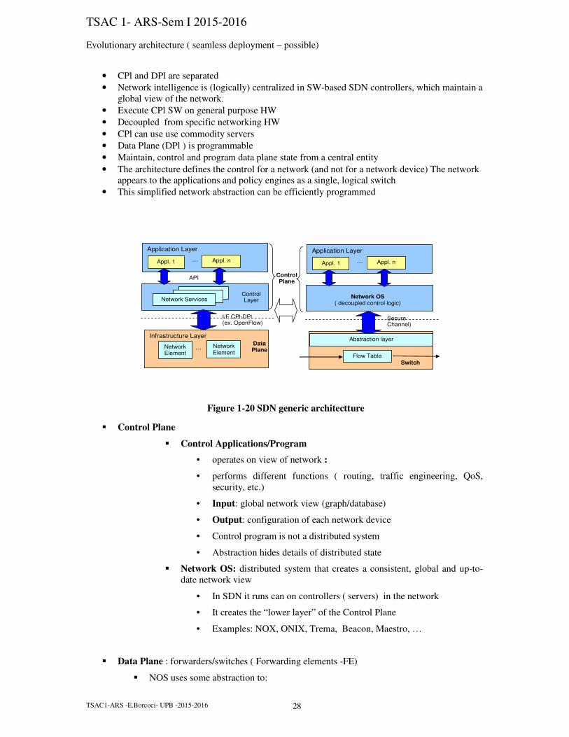
Evolutionary architecture ( seamless deployment – possible)
• CPl and DPl are separated
• Network intelligence is (logically) centralized in SW-based SDN controllers, which maintain a
global view of the network.
• Execute CPl SW on general purpose HW
• Decoupled from specific networking HW
• CPl can use use commodity servers
• Data Plane (DPl ) is programmable
• Maintain, control and program data plane state from a central entity
• The architecture defines the control for a network (and not for a network device) The network
appears to the applications and policy engines as a single, logical switch
• This simplified network abstraction can be efficiently programmed
Infrastructure Layer
Application Layer
Appl. 1 … Appl. n
I/F CPl-DPl (ex. OpenFlow)
Data Plane
Network Services
Network Element
Network Element
…
Control Plane
Application Layer
Appl. 1 … Appl. n
Secure Channel)
Switch
Flow Table
Abstraction layer
Network OS ( decoupled control logic)
API
Control Layer
Figure 1-20 SDN generic architectture
� Control Plane
� Control Applications/Program
• operates on view of network :
• performs different functions ( routing, traffic engineering, QoS,
security, etc.)
• Input: global network view (graph/database)
• Output: configuration of each network device
• Control program is not a distributed system
• Abstraction hides details of distributed state
� Network OS: distributed system that creates a consistent, global and up-to-
date network view
• In SDN it runs can on controllers ( servers) in the network
• It creates the “lower layer” of the Control Plane
• Examples: NOX, ONIX, Trema, Beacon, Maestro, …
� Data Plane : forwarders/switches ( Forwarding elements -FE)
� NOS uses some abstraction to:

TSAC 1- ARS-Sem I 2015-2016
TSAC1-ARS -E.Borcoci- UPB -2015-2016 29
� Get state information from FE
� Give control directives to FE
� Advantages
� Centralization allows:
� To alter network behavior in real-time and faster deploy new applications and network
services (hours, days not weeks or months as today).
� flexibility to configure, manage, secure, and optimize network resources via dynamic,
automated SDN programs ( not waiting for vendors) .
� APIs facilitate implementation of:
� common network services: routing, multicast, security, access control, bandwidth
management, QoS, traffic engineering, processor and storage optimization, energy
usage
� policy management, custom tailored to meet business objectives
� Easy to define and enforce consistent policies across both wired and wireless
connections on a campus
� SDN control and applications layers, business apps can operate on an abstraction of the
network, leveraging network services and capabilities without being tied to the details of their
implementation
� Manage the entire network : intelligent orchestration and provisioning systems
� ONF studies open APIs to promote multi-vendor management:
� possibility for on-demand resource allocation, self-service provisioning,
truly virtualized networking, and secure cloud services.

TSAC 1- ARS-Sem I 2015-2016
TSAC1-ARS -E.Borcoci- UPB -2015-2016 30

TSAC 1- ARS-Sem I 2015-2016
TSAC1-ARS -E.Borcoci- UPB -2015-2016 31
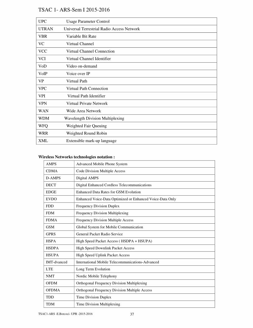
1.6 General list of acronyms
AAA Authentication, Authorisation and Accounting
ABR Available Bit Rate
AC Admission Control
ADSL Asymmetric Digital Subscriber Line
AF Assured Forwarding
AN Access Network
ANG Access Network Gateway
AP Access Point
API Application Programming Interface
AQ&S Advanced Queuing and Scheduling
AQM Advanced (Queue) Management
AR Access Router
ARP Address Resolution Protocol
ARQ Automatic Repeat Request
AS Autonomous System
ATM Asynchronous Transfer Mode
BA Behaviour Aggregate
BB Bandwidth Broker
BE Best Effort
BGP Border Gateway Protocol
BISDN Broadband Integrated Services Digital Network
BR Border Router
CA Congestion Avoidance
CAC Connection Admission Control
CAS Channel Associated Signalling
CBQ Class Based Queuing
CBR Constraint-based Routing
CBR Constant Bit Rate
CC Content Consumer
CDMA Code Division Multiple Access
CDV Cell Delay Variation
CER Cell Error Rate
CES Circuit Emulation Service
CIM Common Information Model
CL Connectionless

TSAC 1- ARS-Sem I 2015-2016
TSAC1-ARS -E.Borcoci- UPB -2015-2016 32
CLI Command Line Interface
CLP Cell Loss Priority
CLR Cell Loss Rate
CMR Cell Misinsertion Rate
CO Connection Oriented
COPS Common Open Policy Service Protocol
CP Content Provider
CPCS Common Part Convergence Sublayer
CPE Customer Premises Equipment
CR Core Router
CS Convergence sublayer (adaptation)
cSLA Customer Service Level Agreement
cSLS SLS between customers and providers
cSLS Customer Service Level Specification
DB Database
DCCP Datagram Congestion Control Protocol
DI Digital Item
DiffServ Differentiated Services
DLCI Data Link Connection Identifier
DNS Domain Name Service
DS Differentiated Services (DiffServ), IETF Working Group
DSCP Differentiated Services Code Point
DSL Digital Subscriber Line
DSLAM Digital Subscriber Line Access Multiplexer
DVA Distance Vector Algorithm
DVB-S Digital Video Broadcast- Sattelite
DVB-T Digital Video Broadcast- Terrestrial
E2E End-to-End
ECN Explicit Congestion Notification
EF Expedited Forwarding
EFSM Extended Finite State Machines
EG Exterior(Border) Gateway
ER Edge Router
ES/H End System/Host
FCFS First Come First Served
FDM Frequency Division Multiplexing
FDMA Frequency Division Multiple Access
FEC Forward Error Control
FEC Forwarding Equivalence Class

TSAC 1- ARS-Sem I 2015-2016
TSAC1-ARS -E.Borcoci- UPB -2015-2016 33
FIFO First-In First-Out (queue)
FR Frame Relay
GFC Generic Flow Control
GK Gate Keeper
GOP Group of Pictures
GPS Global Position System
GRED Generalized RED
GSM Global System for Mobile Communication
GW Gateway
HDSL High bit-rate Digital Subscriber Line
HEC Header Error Check
HTML Hypertext Mark-up Language
HTTP Hyper Text Transfer Protocol (IETF, W3C)
H-WRR Hierarchical WRR
IAB Internet Architecture Board
ICMP Internet Control Messages Protocol
IE Information Element
IEEE Institute of Electrical and Electronics Engineers
IETF Internet Engineering Task Force
IG Interior Gateway( Router)
IMA Inverse Multiplexing ATM
IMS IP Multimedia Subsystem
IntServ Integrated Services
IP Internet Protocol
IPC Inter Process Communication
IRTF Internet Research Task Force
IS Intermediate System
LAN Local Area Network
LANE LAN emulation
LAPD Link Access Procedure for D Channel
LB Leaky Bucket
LDAP Large Directories Access Protocol
LDP Label Distribution Protocol
LLC Logical Link Control
LSP Label Switched Path
LSR Label Switched Route
LVC Label Virtual Circuit
MAC Medium Access Control
MAN Metropolitan Area Network

TSAC 1- ARS-Sem I 2015-2016
TSAC1-ARS -E.Borcoci- UPB -2015-2016 34
MCTD Mean Cell Transfer Delay
MDT Mean down-time
MF Multi Field
MGCP Media Gateway Control Protocol
MGW Media Gateway
MIB Management Information Base
MPEG Moving Picture Experts Group
MPLS Multiprotocol Label Switching
MPOA Multiprotocol over ATM
MSC Message Sequence Chart
MT Mobile Terminal
MTTR Mean time to repair/patch
NC Network Controller
NE Network Element
NGN Next Generation Network
NLRI Network Layer Reachability Information
NM Network Manager
NNI Network Network Interface
NP Network Provider
NPA Network Point of Attachment ( Physical Address)
NQoS Network QoS
nrt-VBR Non-real-time Variable Bit Rate
NSAP Network Service Access Point
NSIS Next Steps in Signalling
NTP Network Time Protocol
OA Ordered Aggregate
OAM Operation and Maintenance
OFDM Orthogonal Frequency Division Multiplexing
OSF Open Software Foundation
OSI - RM Open System Interconnection - Reference Model
OSPF Open Shortest Path First
PBM Policy Based Management
PBNM Policy Based Network Management
PCM Pulse Code Modulation
PDB Per Domain Behaviour
PDH Plesiochronous Digital Hierarchy
PDP Policy Decision Point
PDU Protocol Data Unit
PDV Packet Delay Variation

TSAC 1- ARS-Sem I 2015-2016
TSAC1-ARS -E.Borcoci- UPB -2015-2016 35
PEP Policy Enforcement Point
PHB Per Hop Behaviour
PHP Penultimate Hop Popping
PID Program Identifier
PIM Protocol Independent Multicast
PMD Physical Medium Dependent
PMT Policy management tool
PNNI Private Network-Network Interface
POSIX Portable Operating System Interface
POTS Plain Old Telephone Service
PPP Point to Point Protocol
PQ Priority Queuing
PQoS Perceived QoS
PR Policy Repository
PRIO Priority
pSLA Provider Service Level Agreement
pSLS SLS between providers
pSLS Provider Service Level Specification
PSTN Public Switched Telephone Network
PT Payload Type
PTD Packet Transfer Delay
QC Quality of Service Class
QoS Quality of Services
RARP Reverse Address Resolution Protocol
RED Random Early Drop
RFC Request for Comments
RIP Routing Information Protocol
RM Resource Manager
RSVP Resource reservation protocol
rt -VBR Real-time Variable Bit Rate
RTCP Realtime Control Protocol
RTD Round Trip Delay
RTP Realtime Transport Protocol
RTT Round Trip Time
SAC Subscription Admission Control
SAP Service Access Point
SAR Segmentation/reassembling
SCTP Stream Control Transmission Protocol
SDH Synchronous Digital Hierarchy

TSAC 1- ARS-Sem I 2015-2016
TSAC1-ARS -E.Borcoci- UPB -2015-2016 36
SDR Service Discovery Repository
SDU Service Data Unit
SIP Session Initiation Protocol
SLA Service Level Agreement
SLS Service Level Specification
SM Service Manager
SMI Structure of Management Information
SMTP Simple Mail Transfer Protocol
SNDAP Subnetwork Dependent Network Access Protocol
SNDCP Subnetwork Dependent Convergence Protocol
SNMP Simple Network Management Protocol
SOAP Simple Object Access Protocol
SONET Synchronous Optical Network
SP Service Provider
SQL Structured Query Language
SS7 Signalling System No.7
SSCS Service Specific Convergence Sublayer
STP Signaling Transfer Point
SVC Signalling Virtual Channels
TBF Token Bucket Flow
TC Traffic Control
TCP Transmission Control Protocol
TCS Traffic Conditioning Specification
TD Traffic Demand
TDM Time Division Multiplexing
TDM Terminal Device Manager
TE Traffic Engineering
TLI Transport Layer Interface
TME Existing Subscriptions TM
TMN New Subscriptions TM
TP Traffic Policing
TS Traffic Shaping
TSAP Transport Service Access Point
TSPEC Traffic Specification
TT Traffic Trunk
UBR Unspecified Bit Rate
UDP User Datagram Protocol
UED User Environment Description
UNI User network Interface
TSAC 1- ARS-Sem I 2015-2016
TSAC1-ARS -E.Borcoci- UPB -2015-2016 37
UPC Usage Parameter Control
UTRAN Universal Terrestrial Radio Access Network
VBR Variable Bit Rate
VC Virtual Channel
VCC Virtual Channel Connection
VCI Virtual Channel Identifier
VoD Video on-demand
VoIP Voice over IP
VP Virtual Path
VPC Virtual Path Connection
VPI Virtual Path Identifier
VPN Virtual Private Network
WAN Wide Area Network
WDM Wavelength Division Multiplexing
WFQ Weighted Fair Queuing
WRR Weighted Round Robin
XML Extensible mark-up language
Wireless Networks technologies notation :
AMPS Advanced Mobile Phone System
CDMA Code Division Multiple Access
D-AMPS Digital AMPS
DECT Digital Enhanced Cordless Telecommunications
EDGE Enhanced Data Rates for GSM Evolution
EVDO Enhanced Voice-Data Optimized or Enhanced Voice-Data Only
FDD Frequency Division Duplex
FDM Frequency Division Multiplexing
FDMA Frequency Division Multiple Access
GSM Global System for Mobile Communication
GPRS General Packet Radio Service
HSPA High Speed Packet Access ( HSDPA + HSUPA)
HSDPA High Speed Downlink Packet Access
HSUPA High Speed Uplink Packet Access
IMT-dvanced International Mobile Telecommunications-Advanced
LTE Long Term Evolution
NMT Nordic Mobile Telephony
OFDM Orthogonal Frequency Division Multiplexing
OFDMA Orthogonal Frequency Division Multiple Access
TDD Time Division Duplex
TDM Time Division Multiplexing

TSAC 1- ARS-Sem I 2015-2016
TSAC1-ARS -E.Borcoci- UPB -2015-2016 38
TDMA Time Division Multiple Access
TD-SCDMA Time Division Synchronous Code Division Multiple Access
UMTS Universal Mobile Telecom System
WIMAX Worldwide Interoperability for Microwave Access
WCDMA Wideband Code Division Multiple Access