Embed Size (px)
Citation preview
J. Appl. Environ. Biol. Sci., 4(7S)193-198, 2014
© 2014, TextRoad Publication
ISSN: 2090-4274 Journal of Applied Environmental
and Biological Sciences
www.textroad.com
* Corresponding Author: Nauman Anwar Baig, Department of Electrical Engineering, NUST College of EME. Email: [email protected]
Architecture for Range, Doppler and Direction finding Radar
Nauman Anwar Baig1, Mohammad Bilal Malik
1, Asim Ejaz
1, Khalid Munawar
2
1Department of Electrical Engineering, NUST College of EME
2Department of Electrical Engineering, KAU Saudi Arabia
Received: September 1, 2014
Accepted: November 13, 2014
ABSTRACT
Radar signal processing is a well-established field. Accurate and efficient information extraction related to
target is main goal of a radar designer. As it has applications in many areas, different architectures have been
proposed for its signal processor. Radar capable of localizing a target can be used with missile launcher to hit
the target. A radar signal processor with range, Doppler and direction of arrival estimation is presented with
its architecture on FPGA.
KEYWORDS: Radar; Target; FPGA; Correlation; Doppler; Direction of arrival.
1. INTRODUCTION
Radars can be used for ground and air surveillance. History of Radar lies back to world-war II [1]. A
pulse Doppler radar is capable of finding range, Doppler and direction of a target. Architectures of Radar
signal processors are given in [2] specifically for Automotive applications is given in [3]. Pulse Doppler
radar transmits pulses and the reflected Echoes are processed to target’s information. The reflected pulses
return to the Radar antenna, which are processed using FPGA, DSP etc. to obtain required parameters. In
this paper, we have discussed Radar signal processor of a Pulse Doppler radar capable of finding range,
Doppler and direction. Method for finding direction of arrival using 2x2 Array is discussed with its
embedded architecture. Design methods and FPGA block diagram discussed are helpful for a Radar
designer.
The organization of this paper is now presented. Section II in this paper discusses the algorithm used for
finding range and Doppler of target. Section III gives the design methodology of the Radar signal processor
and details of FPGA are shown in that section. Estimation of direction of arrival using array is presented in
section VII. Finally section VII concludes the paper.
2. Algorithm for Range/Doppler Processing. Radar Antenna transmits pulses with a PRF of 600 Hz,
each PRI is 3ms long with 20 % duty cycle. The received pulses after reflection are stacked in a matrix.
There are 214
samples in one PRI (3 ms) after A/D. Fig. 1 shows the stacked pulses for 2 targets.
Figure1. Stacked pulses
The Matrix is then passed through column wise FFT which gives Doppler axis [4]. After which
correlation is performed row wise which results in range axis. Correlation is performed by using the fast
correlation procedure [5]. After correlation of the rows, peaks are obtained corresponding to targets. The
primary axis represents range and secondary axis represents Doppler. Thresholding gives much smoother
peaks. The summary of algorithm[4] is shown below in Fig. 2
193
BAIG et al.,2014
Figure 2. Algorithm Flow Diagram
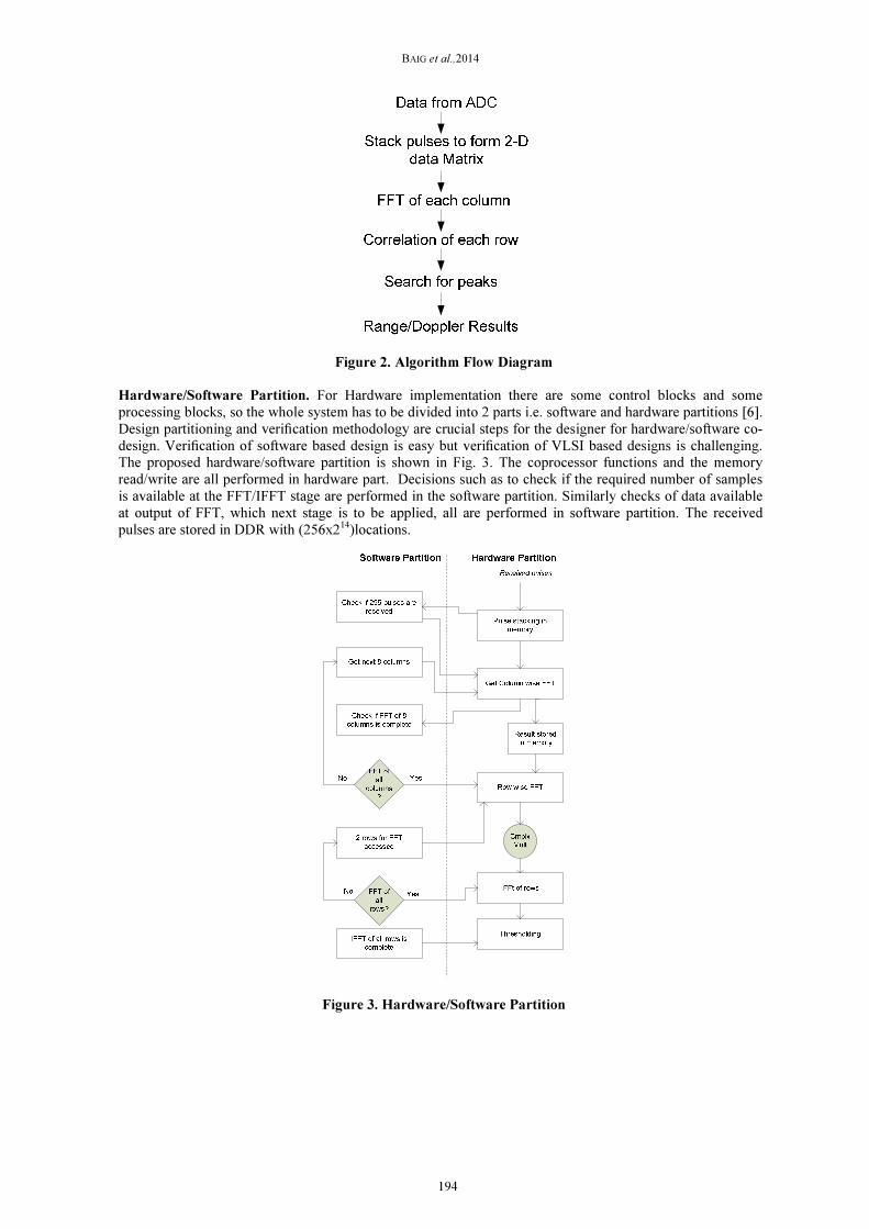
Hardware/Software Partition. For Hardware implementation there are some control blocks and some
processing blocks, so the whole system has to be divided into 2 parts i.e. software and hardware partitions [6].
Design partitioning and verification methodology are crucial steps for the designer for hardware/software co-
design. Verification of software based design is easy but verification of VLSI based designs is challenging.
The proposed hardware/software partition is shown in Fig. 3. The coprocessor functions and the memory
read/write are all performed in hardware part. Decisions such as to check if the required number of samples
is available at the FFT/IFFT stage are performed in the software partition. Similarly checks of data available
at output of FFT, which next stage is to be applied, all are performed in software partition. The received
pulses are stored in DDR with (256x214
)locations.
Figure 3. Hardware/Software Partition
194
J. Appl. Environ. Biol. Sci., 4(7S)193-198, 2014
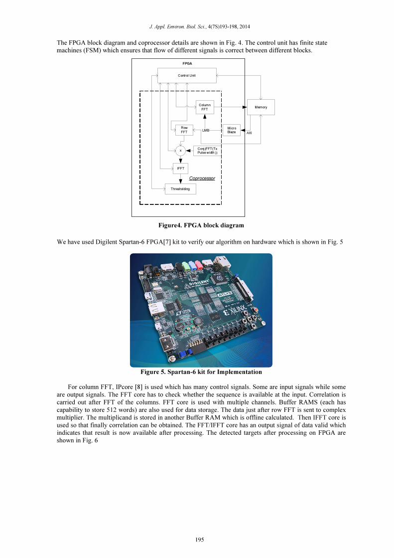
The FPGA block diagram and coprocessor details are shown in Fig. 4. The control unit has finite state
machines (FSM) which ensures that flow of different signals is correct between different blocks.
Control Unit
Thresholding
Conj (FFT(Tx Pulse width ))
IFFT
Row
FFT
Column
FFTMemory
x
FPGA
Micro Blaze
LMBAXI
Coprocessor
Figure4. FPGA block diagram
We have used Digilent Spartan-6 FPGA[7] kit to verify our algorithm on hardware which is shown in Fig. 5
Figure 5. Spartan-6 kit for Implementation
For column FFT, IPcore [8] is used which has many control signals. Some are input signals while some
are output signals. The FFT core has to check whether the sequence is available at the input. Correlation is
carried out after FFT of the columns. FFT core is used with multiple channels. Buffer RAMS (each has
capability to store 512 words) are also used for data storage. The data just after row FFT is sent to complex
multiplier. The multiplicand is stored in another Buffer RAM which is offline calculated. Then IFFT core is
used so that finally correlation can be obtained. The FFT/IFFT core has an output signal of data valid which
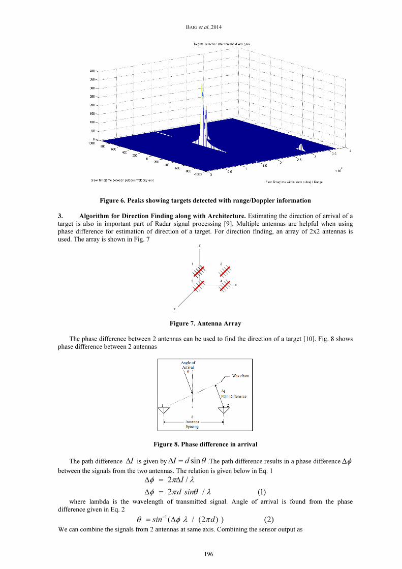
indicates that result is now available after processing. The detected targets after processing on FPGA are
shown in Fig. 6
195
BAIG et al.,2014
Figure 6. Peaks showing targets detected with range/Doppler information
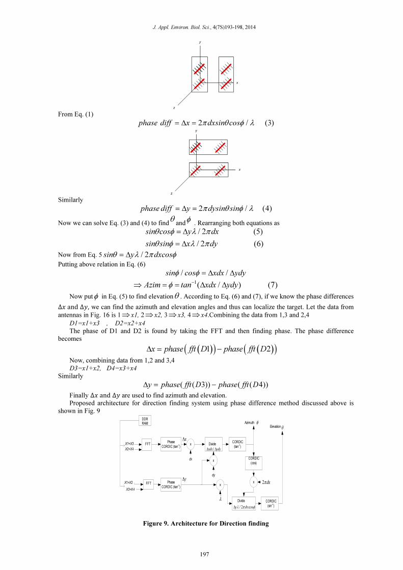
3. Algorithm for Direction Finding along with Architecture. Estimating the direction of arrival of a
target is also in important part of Radar signal processing [9]. Multiple antennas are helpful when using
phase difference for estimation of direction of a target. For direction finding, an array of 2x2 antennas is
used. The array is shown in Fig. 7
Figure 7. Antenna Array
The phase difference between 2 antennas can be used to find the direction of a target [10]. Fig. 8 shows
phase difference between 2 antennas
Figure 8. Phase difference in arrival
The path difference I∆ is given by sinI d θ∆ = .The path difference results in a phase difference φ∆
between the signals from the two antennas. The relation is given below in Eq. 1
2 /
2 / (1)
I
d sin
φ π λ
φ π θ λ
∆ = ∆
∆ =
where lambda is the wavelength of transmitted signal. Angle of arrival is found from the phase
difference given in Eq. 2 1 / ( (2 ) ) (2) sin dθ φ λ π−
= ∆
We can combine the signals from 2 antennas at same axis. Combining the sensor output as
196
J. Appl. Environ. Biol. Sci., 4(7S)193-198, 2014
From Eq. (1)
2 / (3)phase diff x dxsin cosπ θ φ λ= ∆ =
Similarly
2 / (4)phase diff y dysin sinπ θ φ λ= ∆ =
Now we can solve Eq. (3) and (4) to findθ
andφ
. Rearranging both equations as
/ 2 (5)
/ 2 (6)
sin cos y dx
sin sin x dy
θ φ λ π
θ φ λ π
= ∆
= ∆
Now from Eq. 5 / 2sin y dxcosθ λ π φ= ∆
Putting above relation in Eq. (6)
/ /sin cos xdx ydyφ φ = ∆ ∆
1( / ) (7)Azim tan xdx ydyφ −
⇒ = = ∆ ∆
Now putφ in Eq. (5) to find elevationθ . According to Eq. (6) and (7), if we know the phase differences
∆� and ∆�, we can find the azimuth and elevation angles and thus can localize the target. Let the data from
antennas in Fig. 16 is 1⇒ x1, 2⇒ x2, 3⇒ x3, 4⇒ x4.Combining the data from 1,3 and 2,4
D1=x1+x3 , D2=x2+x4
The phase of D1 and D2 is found by taking the FFT and then finding phase. The phase difference
becomes
( )( ) ( )( )1 2x phase fft D phase fft D∆ = −
Now, combining data from 1,2 and 3,4
D3=x1+x2, D4=x3+x4
Similarly
( ( )) ( ( ))3 4y phase fft D phase fft D∆ = −
Finally ∆� and ∆� are used to find azimuth and elevation.
Proposed architecture for direction finding system using phase difference method discussed above is
shown in Fig. 9
x
DDR RAM
CORDIC(tan-1)
DividePhase
CORDIC (tan-1)FFT
/xdx ydy∆ ∆
X1+X3
X2+X4
dx
x∆
CORDIC(sin -1)
Divide
Phase CORDIC (tan-1)
FFT
dyy∆
X3+X4
X1+X2
x
x
λ
Azimuth φ
CORDIC(cos)
x 2 dxπ
/ 2 cosy dxλ π φ∆
θElevation
Figure 9. Architecture for Direction finding
197

BAIG et al.,2014
4. Conclusions. Pulse Doppler Radar signal processor for air surveillance is simulated using MATLAB
and then FPGA is used for testing the algorithm on processor. The design approach is explained with
hardware/software partition and system block diagram. Antenna array system for direction finding was
presented with its architecture. The results for simulation and hardware show that our system is working fine
in presence of noisy signals.
5. Acknowledgement. The authors would like to thank NUST and HEC for the financial support. We
also appreciate the help given by Zeeshan, Waqas and Razi Ahmed.
REFERENCES
[1] Jeff Duda, “A History of Radar Meteorology:People, Technology, and Theory”.
[2] Charles Buenzli, Lee Owen, Fred Rose, “Hardware/Software Codesign of a Scalable Embedded Radar
Signal Processor”, VHDL International Users' Forum, 1997.
[3] Kim, Y.Ju, and J.Lee, “Design and implementation of a full-digital pulse-doppler radar system for
automotive applications,” Consumer Electronics (ICCE), 2011 IEEE International Conference on
.IEEE, 2011, pp.563–564.
[3] M.Skolnik, Introduction to Radar Systems 3/E. McGraw-HillEducationPvt.Ltd,2001.
[4] Richards, M.A., Fundamentals of Radar Signal Processing, Mc-Graw Hill, 2005.
[5] Byron Edde, Radar: Principles, Technology, Applications,Pearson education.
[6] Shoab Ahmed Khan, Digital Design of Signal Processing Systems, a Practical Approach, John Willey
and Sons.
[7] Digilent, Atlys Spartan-6.
[8] Xilinx datasheet, Logi CORE IP Fast Fourier Transform v7.1, DS 260, 2011.
[9] ]Nauman Anwar Baig, Mohammad Bilal Malik, “Comparison of Direction of Arrival (DOA) Estimation
Techniques for Closely Spaced Targets”, International Conference on Intelligence and Information
Technology, IEEE (ICIIT), vol. 2, 345-350, 2010, Pakistan.
[10] Bassem R. Mahafza, “Radar Systems Analysis and Design Using MATLAB”, CHAPMAN &
HALL/CRCBoca Raton London New York Washington, D.C.
198