Embed Size (px)
Citation preview

Architecture, Analysis &Design of Skyscraper
Under the esteemed guidance of
Mr. Botsa Srinivasa Rao
M. Tech, Structural Engineering, IIT Guwahati
Lecturer, RGUKT – Nuzvid
By
N091918 – M Venu
N100246 – K N S Varsha
N100505 – M Ravi Teja
N100603 – Ch Chandra Kala
N100654 – J L Harika(Civil Engineering, Batch 2016)

Contents
o Introduction
o Software
o Structural Systems
o Planning
o Architecture
o Loads
o Shear wall
o Modelling
o Analysis
25-Apr-16 B. Tech Project - RGUKT Nuzvid 2
o Design
o Results
o Conclusion
o Future scope
o References

Introduction
• Scarcity of land
• Leaping demand for business and residential space
• Thriving economies and booming populations
• Broad casting and research facilities
• Advancements and innovations in structural systems
• Desire for aesthetics
• Tallness of building is more often relative
• Skyscrapers are in general a height greater than 150m
25-Apr-16 B. Tech Project - RGUKT Nuzvid 3

Introduction (Contd.)
• ‘skyscraper’ was coined in 1880s
• Steel has made it all possible
• 1st ever tall building
• Home Insurance Building in Chicago
• Height - 42 m.
• Greater than 150 m as per CTBUH
• Super tall (>300 m)
• Mega tall (>600 m)
• Greater than 15 m as per NBC
• Greater than 21 m as per US General Laws
25-Apr-16 B. Tech Project - RGUKT Nuzvid 4

Softwares
• ETABS (Extended Three dimensional Analysis of Building
Structures) – Computers and Structure Inc.
• Revit Architecture - Autodesk
• AutoCAD – Autodesk
• Pile - Oasys
• MS Excel - Microsoft
25-Apr-16 B. Tech Project - RGUKT Nuzvid 5

Components of tall buildings
• Floor systems
• Gravity load resisting systems
• Lateral load resisting systems
• Connections
• Damping systems
25-Apr-16 B. Tech Project - RGUKT Nuzvid 6

Structural systems
• Knowing the skeleton
25-Apr-16 B. Tech Project - RGUKT Nuzvid 7
Fig.1 Evolution of Structural Systems

Structural systems (Contd.)
• Knowing the interlinks
25-Apr-16 B. Tech Project - RGUKT Nuzvid 8
Fig.2 Classification of Structural Systems

Structural systems (Contd.)
• Moment resisting frames
• Shear frames
• Frame with shear resisting trusses – Interacting
• End channel framed tube with interior trusses – Partial tube
• Exterior framed tube or bundled tube
• Exterior diagonalized tube
25-Apr-16 B. Tech Project - RGUKT Nuzvid 9
Fig.3 Framed tube

Preferred structural system
• Tube in Tube (Hull and Core)
• Similar to Hollow Cantilever beam
• More column free space
• Lateral stiffness by the perimeter frame
• Maximum bending rigidity
• Flange frames normal to the wind carry axial loads
• Web frames parallel to the wind carry shear
25-Apr-16 B. Tech Project - RGUKT Nuzvid 10
Structural systems (Contd.)
Fig.4 Unfolded plane frame

Planning
25-Apr-16 B. Tech Project - RGUKT Nuzvid 11
• Core covers 25% of the total built up area
• Built up area: 13, 600 sq. m
• Core : 3,400 sq. m
Fig.5 Proposed layout of the skyscraper

Planning (Contd.)
• Built up area : 936 sq. m
• Core area: 234 sq. m
• Minimum built up area: 800 sq. m
25-Apr-16 B. Tech Project - RGUKT Nuzvid 12
Fig.6 Scaled layout – Tube in tube

Planning (Contd.)
• Flange planes – overturning moment
• Web planes – lateral shear force
25-Apr-16 B. Tech Project - RGUKT Nuzvid 13
Fig.7 Total layout of the skyscraper

Planning (Contd.)
Child Bed rooms
M Bed room
M Bed room M Bed room
M Bed room
Child Bed rooms
Kitchen
Child Bed rooms Child Bed rooms
Kitchen
Core with elevators
Dining
Dining
Fig.8 Floor plan of the residential stories
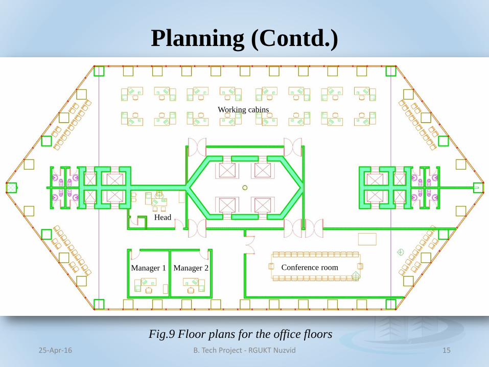
Planning (Contd.)
25-Apr-16 B. Tech Project - RGUKT Nuzvid 15
Conference room
Working cabins
Manager 1 Manager 2
Head
Fig.9 Floor plans for the office floors

Planning (Contd.)
25-Apr-16 B. Tech Project - RGUKT Nuzvid 16
Terrace area
Res
taura
nt
Res
taura
nt
Elevators Elevators
Spine
Fig.10 Floor plans for the restaurant
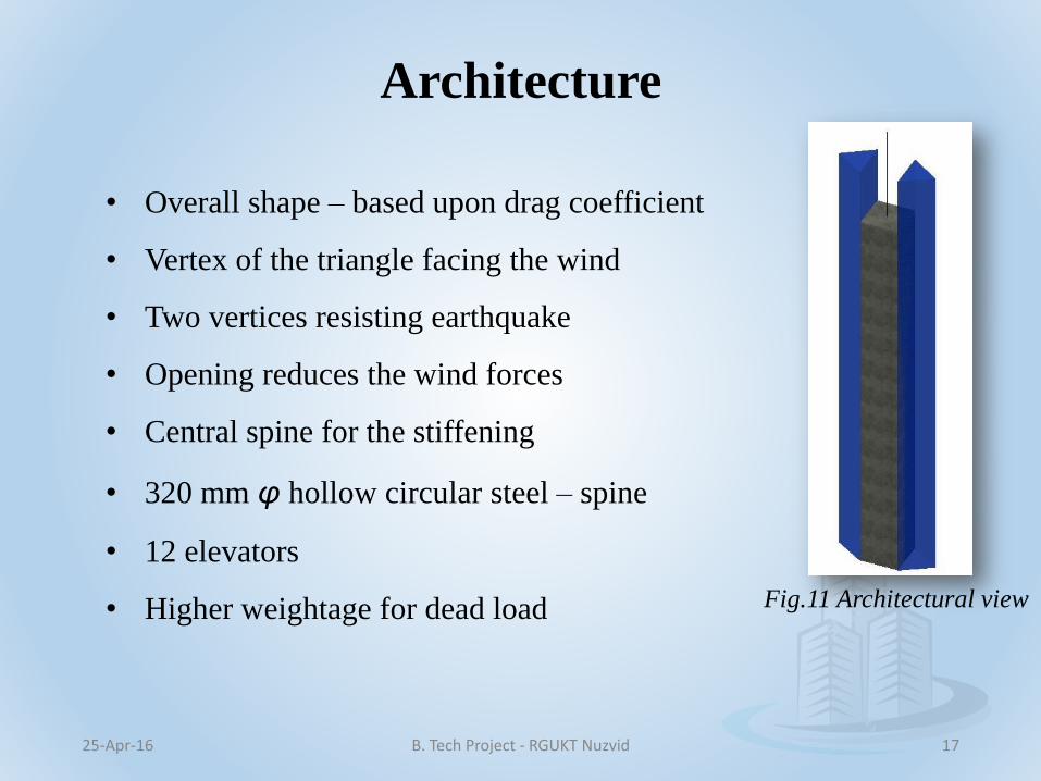
Architecture
• Overall shape – based upon drag coefficient
• Vertex of the triangle facing the wind
• Two vertices resisting earthquake
• Opening reduces the wind forces
• Central spine for the stiffening
• 320 mm φ hollow circular steel – spine
• 12 elevators
• Higher weightage for dead load
25-Apr-16 B. Tech Project - RGUKT Nuzvid 17
Fig.11 Architectural view
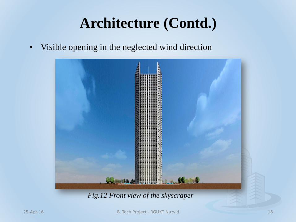
Architecture (Contd.)
• Visible opening in the neglected wind direction
25-Apr-16 B. Tech Project - RGUKT Nuzvid 18
Fig.12 Front view of the skyscraper

Architecture (Contd.)
• Front yard and rear yards – 10 m. each
• Side yard – 6 m
• Total plot area: 2674 sq. m
25-Apr-16 B. Tech Project - RGUKT Nuzvid 19
Fig.13 Front perspective

Architecture (Contd.)
• Front door – 1.5 m each
25-Apr-16 B. Tech Project - RGUKT Nuzvid 20
Fig.14 Entrance through revolving doors

Architecture (Contd.)
• Bed room – 23. 88 sq. m
• Minimum – 12 sq. m
25-Apr-16 B. Tech Project - RGUKT Nuzvid 21
Fig.15 Bed room
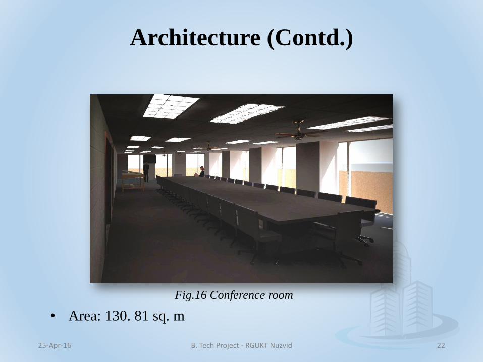
Architecture (Contd.)
• Area: 130. 81 sq. m
25-Apr-16 B. Tech Project - RGUKT Nuzvid 22
Fig.16 Conference room

Architecture (Contd.)
• Terrace area: 695 sq. m
25-Apr-16 B. Tech Project - RGUKT Nuzvid 23
Fig.17 Sky line view

Architecture (Contd.)
• Area of each restaurant: 82.50 sq. m
25-Apr-16 B. Tech Project - RGUKT Nuzvid 24
Fig.18 Inner view of restaurant

Architecture (Contd.)
• Analogous to isometric view
25-Apr-16 B. Tech Project - RGUKT Nuzvid 25
Fig.19 Perspective view

Loads• Dead load
• Live load
• Earthquake load
• Wind load (Arrow indicates the direction of wind)
25-Apr-16 B. Tech Project - RGUKT Nuzvid 26
𝐶𝑑 = 1.2 𝐶𝑑 = 1.4
𝐶𝑑 = 2.0 𝐶𝑑 = 2.2
𝐶𝑑 = 2.2 𝐶𝑑 = 1.5
Fig.20 Drag coefficients for different shapes

Loads (Contd.)
• Seismic zone – III
• Critical wind and MCE will not occur simultaneously
• Considering equivalent static design base shear
25-Apr-16 B. Tech Project - RGUKT Nuzvid 27
S. No Parameter Magnitude/Description
1. Basic Wind speed (Vb) 50 m/sec
2. Terrain Category 4
3. Class of the structure C
4. TopographyNumerous large high closely
spaced obstructions
5. Life of the structure(N) 100 yrs.
6. Wind zone 5
Table.1 Wind data for the skyscraper

Shear wall
25-Apr-16 B. Tech Project - RGUKT Nuzvid 28
Fig.21 Models – 1,2,3,4

Shear wall (Contd.)
25-Apr-16 B. Tech Project - RGUKT Nuzvid 29
Fig. 22 Model - 5

Shear wall (Contd.)
25-Apr-16 B. Tech Project - RGUKT Nuzvid 30
Fig.23 Maximum Joint displacements under gravity loading
0
1
2
3
4
5
6
7
0 1 2 3 4 5 6 7 8
Sto
rey N
o
Joint displacement (mm)
Joint displacements for gravity loading
without shear wall
Shear wall at Core
Shear wall at edges
Shear wall at Corners
At core without beams

Shear wall (Contd.)
25-Apr-16 B. Tech Project - RGUKT Nuzvid 31
Fig. 24 Applied Lateral loading the joints of floors
0 100 200 300 400 500
Story 6
Story 5
Story 4
Story 3
Story 2
Story 1
Base
Lateral load onto the floors
Lateral load(kN)

Shear wall (Contd.)
25-Apr-16 B. Tech Project - RGUKT Nuzvid 32
Fig.25 Maximum Joint displacements under Gravity loading + Lateral loading
0
1
2
3
4
5
6
7
0 15 30 45 60 75 90 105 120 135 150 165 180 195 210 225 240 255
Sto
rey N
o
Displacement(mm)
With Lateral loading

Shear wall (Contd.)
25-Apr-16 B. Tech Project - RGUKT Nuzvid 33
Efficiency of the models
With Gravity loading alone,
Model 5 = Model 2 > Model 4 = Model 3 > Model 1
With Gravity loading + Lateral loading
Model 5 ≈ Model 2 > Model 4 > Model 3 > Model 1

Modelling
• Grid based modelling of the structure
• Columns for the hull
• Connecting through beams
• Core with Shear Walls
• Replicate up to 50 stories
• Defining material and section properties
• Assigning material and section properties
• Defining load cases, patterns and combinations
• Applying the loads
• Setting load cases to run, analysis and design
25-Apr-16 B. Tech Project - RGUKT Nuzvid 34

Modelling (Contd.)
25-Apr-16 B. Tech Project - RGUKT Nuzvid 35
Fig.26 Grid and Columns for the hull
Fig.27 3 D view of story 1
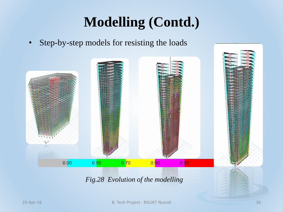
Modelling (Contd.)
25-Apr-16 B. Tech Project - RGUKT Nuzvid 36
Fig.28 Evolution of the modelling
• Step-by-step models for resisting the loads
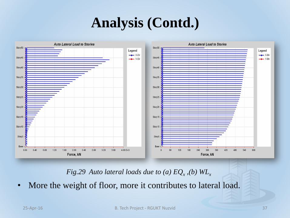
Analysis (Contd.)
25-Apr-16 B. Tech Project - RGUKT Nuzvid 37
Fig.29 Auto lateral loads due to (a) EQx ,(b) WLx
• More the weight of floor, more it contributes to lateral load.
Analysis
• 40 columns and 300 beams
• In the columns
• Critical combination – 1.5(DL+FFL+EQy)
• Max. axial force (P) = 86,769.8 kN; Column in Story 1
• Max. moment (M2) = 5717.6 kN – m; Column in story 8
• In the beams
• Critical combination – 1.5(DL+FFL-EQx)
• Beam beside the core in story 15
• Max. V2 = 2595.34 kN
• Max. M3 = 6265.50 kN-m
25-Apr-16 B. Tech Project - RGUKT Nuzvid 38

Analysis (Contd.)
25-Apr-16 B. Tech Project - RGUKT Nuzvid 39
Fig.30 Drifts for diaphragm (a) without outriggers ,(b) with outriggers
• Outrigger truss – W 40 X 593 of Fe 415
• Location: Every one – third height

Analysis (Contd.)
25-Apr-16 B. Tech Project - RGUKT Nuzvid 40
• Maximum sway: 1 in 357
• Range: 1 in 800 - 1 in 200
Fig.31 Displacements
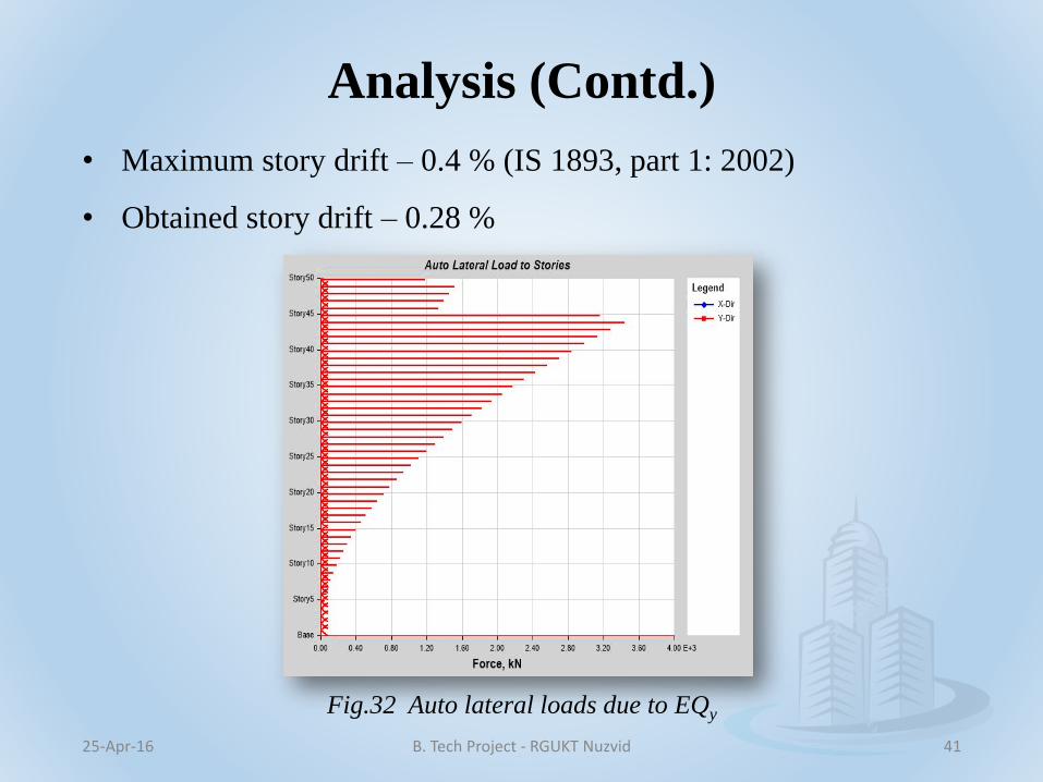
Analysis (Contd.)
25-Apr-16 B. Tech Project - RGUKT Nuzvid 41
• Maximum story drift – 0.4 % (IS 1893, part 1: 2002)
• Obtained story drift – 0.28 %
Fig.32 Auto lateral loads due to EQy

Analysis (Contd.)
25-Apr-16 B. Tech Project - RGUKT Nuzvid 42
Fig.33 Story shears and overturning moment
• Base shear force – 93, 000 kN
• Overturning moment (x) – 46 X 106 kN-m
• Overturning moment (y) – 65 X 106 kN-m

Analysis (Contd.)
25-Apr-16 B. Tech Project - RGUKT Nuzvid 43
• Modal analysis – deflected shape and direction
• 12 modes – may vary based on time period
• Arbitrary scaling
• Period of vibration decreases with increase in mode number
Fig.34 All the mode shapes
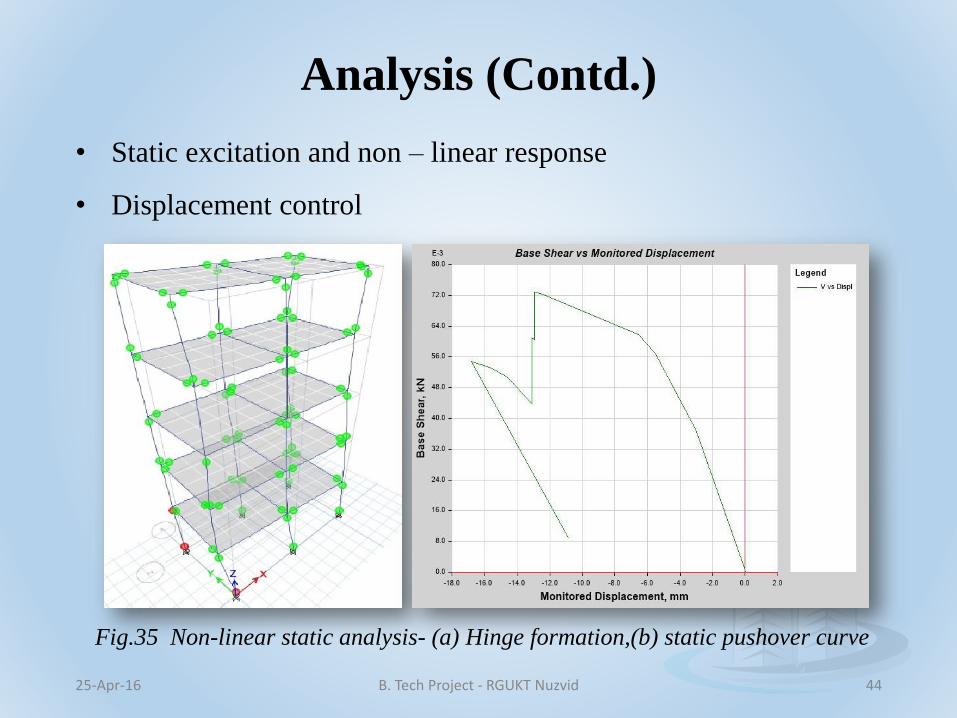
Analysis (Contd.)
25-Apr-16 B. Tech Project - RGUKT Nuzvid 44
Fig.35 Non-linear static analysis- (a) Hinge formation,(b) static pushover curve
• Static excitation and non – linear response
• Displacement control

Design
• Beam design – IS 456: 2000
• Reinforcement – 1.99 %
25-Apr-16 B. Tech Project - RGUKT Nuzvid 45
Fig.36 Location of critical beams

• Composite column design
• Embedded I section: W 40 X 593
25-Apr-16 B. Tech Project - RGUKT Nuzvid 46
Design (Contd.)
Fig.37 Beam cross-section
1000mm X 1000mm
Fig.38 Colum cross-section
1500mm X 1500mm
• 50 mm φ longitudinal rebars
• Symmetry reduces crookedness
• Torsional moment – 0.0094 kN – m (negligible for design)

• Composite column design
• Code: AISC 360 -10
25-Apr-16 B. Tech Project - RGUKT Nuzvid 47
Design (Contd.)
Fig.39 Column capacity ratios
• Max. vertical load from an isolated column = 86,770 kN
25-Apr-16 B. Tech Project - RGUKT Nuzvid 48
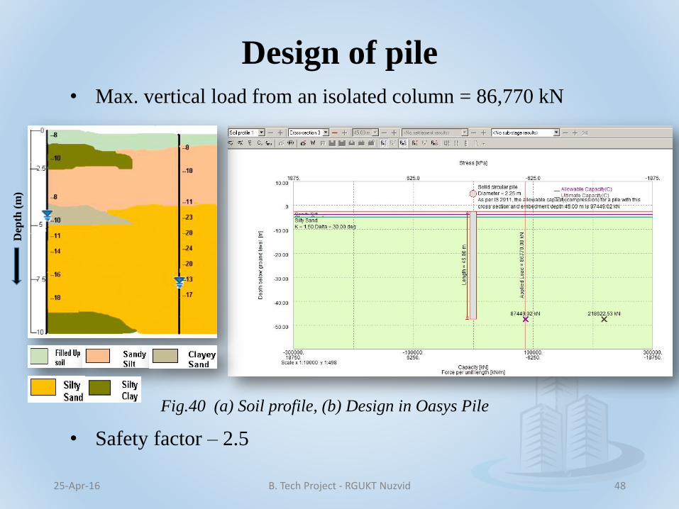
Design of pile
Dep
th (
m)
• Safety factor – 2.5
Fig.40 (a) Soil profile, (b) Design in Oasys Pile

25-Apr-16 B. Tech Project - RGUKT Nuzvid 49
Conclusions
• Architectural views are drawn
• Reduction in torsional moment because of symmetry
• Lateral sway is 44% less compared with the existing ones
• Lateral drift is 0.28% only
• Drift is 86% lesser compared to that of threat to human safety
• Comprehensive Linear static analysis
• Composite Columns are designed
• Isolated pile is designed
• Tube-in-tube system is well appreciated

25-Apr-16 B. Tech Project - RGUKT Nuzvid 50
Future scope
• Increase in base dimension and height of skyscraper
• Employing work station for further analyses
• Non-linear Static analysis by hinge formation
• Non-linear Dynamic analysis for real time response
• Max. displacement during the disasters can be identified
• Design of pile cap over the piles and/or spun piles
References• Aainawala M. S, Dr. Pajgade P. S (2014), “Design of Multistoried R.C.C. Buildings with
and without Shear Walls”, International Journal of Engineering Sciences and Research
Technology, ISSN 2277-9655, Vol.3 (7).
• Taranath B. S (1988), “Structural Analysis and Design of Tall Buildings”, McGraw – Hill
Publishing Company Ltd., ISBN 0-07-062878-5.
• Ali M, Moon K. S (2007), “Structural Developments in Tall Buildings: Current Trends
and Future Prospects”, Architectural Science Review, Vol. 50.3, pp. 2015-223.
• Wagh S.A, Waghe U. P (2014), “Comparative Study of R.C.C and Steel Concrete
Composite Structures”, Int. Journal of Engineering Research and Applications, Vol.4,
Issue 4, pp.369-376.
• David Spires, Arora J.S (1990), “Optimal Design of Tall RC-Framed Tube Buildings”,
Journal of Structural Engineering, ASCE, Vol. 116, No.4.
• Aminmansour A (2010), “Integrated Design and Construction of Tall Buildings”, Journal
of Architectural Engineering, ASCE, Vol. 53.
• Alaghmandan M, Elnimeiri M (2013), “Reducing impact of wind on tall buildings through
design and aerodynamic modifications”, ASCE, pp. 847 -856.
• Chang P.C, Foutch D. A (1984), “Static and dynamic modeling and analysis of tube
frames”, Journal of Structural Engineering, ASCE, Vol.110, No.12, pp.2955-2975.
• Baker W. F et al. (2009),”The Challenges in Designing the World’s Tallest Structure: The
Burj Dubai Tower”, Structures Congress, ASCE, pp. 1471-1480.
25-Apr-16 B. Tech Project - RGUKT Nuzvid 51

25-Apr-16 B. Tech Project - RGUKT Nuzvid 52