Embed Size (px)
Citation preview
DCN Next Generation
en Architect’s &Engineer’sSpecifications

About this Document
PurposeWhen preparing a specification, tender or quotation for a Bosch DCN Next Generation installation, it may be necessary to supply a detailed functional description of all equipment supplied. The Architect’s and Engineer’s Specifications presented in this publication are intended to be used for these purposes, and may be copied and/or reproduced as required.
ScopeDCN Next Generation can be coupled to other systems and networks like Integrus or CobraNet. This Architect’s and Engineer’s Specifications only contains the functional description specific for the DCN Next Generation system.
AudienceThese Architect’s and Engineer’s Specifications meet the needs of contractors, consultants and other professionals involved in project management, or in designing, specifying and procuring congress systems.
CopyrightRobert Bosch GmbH, Germany, owns copyright of these specifications but authorized professional persons and organizations for the purpose of compiling tenders, specification proposals and related documentation in support of their sales and project management activities may reproduce them in whole or in part.
Document FormatThe Architect’s and Engineer’s Specifications are available as a digital document in the Word format (.doc). All references to pages, figures, tables, etc. in this digital document contain hyperlinks to the referenced location.
Special note: conference definitionFor the purpose of this specification, a conference is any gathering of delegates where audio amplification is required
DCN Next Generation Architect’s & Engineer’s Specifications en | 4
Table of contents
1 Introduction.................................................22 Scope of Specification................................23 System summary........................................23.1 System overview...........................................23.2 System functions...........................................23.3 Compliance...................................................23.4 System configuration....................................23.5 System installation and interconnection........23.6 System operation..........................................23.7 Conference or discussion units.....................23.8 First-line system maintenance......................24 Functional description of the system without PC control 24.1 Microphone management.............................24.1.1 System operator............................................24.1.2 Chairman......................................................24.1.3 Delegate........................................................24.2 Vote processing and display.........................24.2.1 Chairman......................................................24.2.2 Delegate........................................................24.3 Interpretation.................................................24.3.1 System operator............................................24.3.2 Interpreter booth equipment..........................24.4 Intercom........................................................24.5 Distribution....................................................24.5.1 Infra-red distribution system..........................24.6 Connecting peripheral equipment.................24.6.1 Hall displays..................................................24.6.2 External system connections........................24.7 Automatic camera control.............................24.7.1 System operator............................................25 Functional description for system with PC control 25.1 Microphone management.............................25.1.1 System operator............................................25.1.2 Chairman......................................................25.1.3 Delegate........................................................25.2 Vote processing and display.........................25.2.1 System operator............................................25.2.2 Chairman......................................................25.2.3 Delegate........................................................25.3 Delegate identification...................................25.4 Interpretation.................................................25.4.1 System operator............................................25.4.2 Interpreter booth equipment..........................25.5 Intercom........................................................25.6 Distribution....................................................25.6.1 Infra-red distribution system..........................25.7 Connecting peripheral equipment.................25.7.1 Hall displays..................................................25.7.2 Printers..........................................................25.7.3 External system connections........................25.8 Automatic camera control.............................26 Contribution equipment.............................26.1 Tabletop discussion units..............................26.1.1 Discussion unit with fixed microphone..........26.1.2 Basic Discussion unit....................................26.1.3 Discussion unit with Channel Selector..........2
Bosch Security Systems | December 2011
DCN Next Generation Architect’s & Engineer’s Specifications en | 5
6.1.4 Discussion Unit with Dual Channel Selectors26.1.5 Discussion Unit with Voting...........................26.1.6 Discussion Unit with Voting and Channel Selector 26.1.7 Pluggable microphone..................................26.1.8 Rims for Discussion Units.............................26.1.9 Buttons for Chairman Discussion Unit..........26.1.10............Buttons for Dual Use Discussion Unit 26.1.11..................Cable clamps for Discussion Unit 26.1.12................................Discussion unit Suitcase 26.1.13...........................Flight Case Discussion Unit 26.2 Tabletop Conference units............................26.2.1 Standard Conference Unit.............................26.2.2 Conference unit with channel selector..........26.2.3 Full Function Conference Unit.......................26.2.4 Conference Chairman Unit............................26.2.5 Pluggable microphone..................................26.2.6 Suitcase for Conference units.......................26.2.7 Intercom Handset..........................................26.2.8 Flight Case Conference Unit.........................26.3 Flush-mounted units.....................................26.3.1 Flush mount interface...................................26.3.2 Hand-held microphone..................................26.3.3 Microphone Connection Panel......................26.3.4 Microphone Control Panel.............................26.3.5 Priority Panel.................................................26.3.6 Loudspeaker Panel.......................................26.3.7 Voting Panel..................................................26.3.8 Voting and Card Panel..................................26.3.9 Blank Panel...................................................26.3.10.......................................................End Caps 26.3.11.......................................................Couplings 26.3.12..................................Flush Positioning Tools 26.3.13...................................Flush Extraction Tools 26.3.14..........................................Intercom Handset 26.3.15.......................................Table Top Housings 26.3.16.....................................................Voting Unit 26.3.17.......................................Voting Unit Chinese 26.4 Wireless discussion units..............................26.4.1 Wireless Discussion Unit...............................26.4.2 Wireless Discussion Unit with Channel Selector 26.4.3 Wireless Dual Discussion Unit......................26.4.4 Wireless Discussion Unit with Dual Channel Selector 26.4.5 Wireless Discussion Unit with Voting............26.4.6 Wireless Discussion Unit with Voting and Channels Selector 26.4.7 Short Pluggable Pluggable microphone........26.4.8 Rims for Discussion Units.............................26.4.9 Buttons for Chairman Discussion Unit..........26.4.10............Buttons for Dual Use Discussion Unit 26.4.11.....Battery Pack for Wireless Discussion Unit 26.4.12..Power Adaptor for Wireless Discussion Unit 26.4.13...............................Wireless Battery Charger 26.4.14...................Flight Case for WCCU and WAP 26.4.15..Roller Case for 10 wireless discussion units 26.4.16. .Flight Case for 10 wireless discussion units 27 Interpretation and Language Distribution Equipment 27.1 Interpreter Desk............................................27.2 Interpreter Headphones................................27.3 Channel Selector unit....................................27.4 Table Top Housings......................................27.5 Lightweight Stereo Headphones...................2
Bosch Security Systems | December 2011
DCN Next Generation Architect’s & Engineer’s Specifications en | 6
7.6 Under-the-Chin Stereo Headphones.............27.7 Single Earphone...........................................27.8 High Quality Dynamic Headphones..............27.9 Induction Loop Neckband.............................27.10 Flight Case....................................................28 Central Control Equipment........................28.1 Basic Central Control Unit.............................28.2 Central control unit........................................28.3 Wireless Access Point..................................28.4 Extension Power Supply...............................28.5 Digital Audio Expander.................................28.6 Audio Expander............................................28.7 Cobranet Interface........................................28.8 Feedback Suppressor...................................28.9 ID Card Encoder...........................................28.10 ID Cards........................................................29 Application software...................................29.1 Introduction...................................................29.2 PC Control Software.....................................29.2.1 Server application.........................................29.2.2 Configuration.................................................29.2.3 Operator application......................................29.2.4 Print application............................................29.3 Microphone Management.............................29.4 Delegate Database.......................................29.5 Parliamentary Voting.....................................29.6 Attendance Registration and Access Control29.7 Application Programmable Interface.............29.8 Streaming Meeting Data...............................29.9 ID Card Encoding..........................................29.10 Simultaneous Interpretation..........................29.11 Individual Channels.......................................29.12 Stand Alone Camera Control........................29.13 Synoptic Microphone and Voting..................210 Information displays...................................210.1 Data Distribution Board.................................210.2 Video Display................................................210.3 Numeric Hall Display.....................................210.4 Alphanumeric Hall Display............................210.5 Geographic Hall Display................................211 Cameras and accessories..........................211.1 Video Switcher..............................................211.2 Video Switcher Keyboard..............................211.3 AutoDome Controller....................................211.4 AutoDome System........................................211.5 Color Camera................................................211.6 LCD Monitor..................................................212 Installation Equipment................................212.1 Trunk Splitter.................................................212.2 Tap-Off Unit..................................................212.3 Extension Cable............................................212.4 cable locking clamps.....................................212.5 Termination plug for cable.............................212.6 Optical network Splitter.................................212.7 Fiber interface without Address.....................212.8 Optical Network Cables.................................212.9 Optical cable & connector tool kit..................212.10Optical cable couplers..................................213 Technical Data..............................................2
Bosch Security Systems | December 2011
DCN Next Generation Architect’s & Engineer’s Specifications en | 7
1 IntroductionThe DCN Next Generation is a conference control system that provides both the users and owners of assembly venues with a versatile means of fulfilling conference requirements. These may range from small gatherings without an operator or chairman to major international events requiring full conference control, interpretation, language distribution, electronic voting and delegate identification facilities.
The modular design of the system enables the required facilities to be specified in any desired configuration, permitting a high degree of system flexibility. The system conforms to all the relevant ISO and IEC standards.
2 Scope of SpecificationThis specification shall cover the provision, installation and maintenance of the DCN Next Generation system that includes specified functions for chairman and delegate identification, participation and voting. It shall also cover simultaneous interpretation on up to 31 separate language channels plus the floor language, and camera control for displaying active delegates on hall displays and monitors. Furthermore it shall cover the provisions of an optical network for advantaged coupling to both analog and digital audio systems, Infrared Language Distribution system and Cobra Net. Next to that this specification shall cover PC control software to control the DCN Next Generation systems by means of a PC or any other remote controller.
3 System summary
3.1 System overviewThe conference system shall provide digital signal processing and transmission of all audio signals via a network system. It shall be low susceptible for mobile phones. It shall provide versatility, high audio quality, data transmission security and simplicity of operation and installation. It shall be possible to use the conference system via a PC running user-friendly software. The software shall assist in preparation, controlling and monitoring.
The conference system shall be a modular system. It shall be possible to connect elements of a system simply and quickly, using a daisy-chain or loop-through configuration. Systems shall be expanded or reduced in size by adding or removing equipment. The conference system shall be suitable for situations from small, informal gatherings up to international multi-lingual congresses up to 31 languages and floor. It shall also be
Bosch Security Systems | December 2011
DCN Next Generation Architect’s & Engineer’s Specifications en | 8
possible to couple rooms with little language to a full size system with up to 31 languages.The range of conference system products shall include central control devices, simultaneous interpretation and language distribution equipment, application-specific software modules, information display systems and installation equipment. This range shall be complemented by external equipment such as video, displays, PCs, monitors, booster amplifiers, cameras and accessories, loudspeakers and printers, all of which shall be fully compatible and easily integrated into the conference system.
Signal transmission and processing shall be by means of advanced digital-audio technology. This advanced digital-audio technology shall result in high-level audio performance (bandwidth up to 20 kHz) with no losses in signal quality or level during transmission. There shall be virtually no background noise, interference, crosstalk or distortion (signal to noise should be at least 80 dB).
A thin, flexible twin-coaxial cable and a thin twin-optical cable shall carry all the system's digital signals. It shall be generally possible to run these cables through existing ducting and cable conduits. The cables shall be able to carry up to 32 high-quality contribution channels, 32 high-quality distribution channels, and 10 separate data channels for messages and other information. It shall be possible to 'tap' these cables at any point to connect extra conference system equipment. Power shall be supplied to all devices via these cables.
The wireless network of the conference system shall be digitally protected via 128bit AES Rijndael encryption against tapping or eavesdropping. It shall operate in the 2.4 GHz band, which is license-free worldwide. The intelligent system shall have features for automatic subscription blocking, to prevent further subscriptions if the administrator forgets to close the subscription process.The wireless discussion system shall have a Wireless Access Point linked to the Central Control Unit using an optical network, which provides digital optical communication and power supply over a single cable.
The Wireless Access Point of the wireless discussion system shall have a second optical network connector to allow the system network to be expanded from a single branch to a redundant loop configuration, to ensure communication between Wireless Access Point and the Central Control Unit in case one of the cables is disconnected or has a malfunction.
The Central Control Unit shall have a built-in tone control function for loudspeakers in contribution devices. This function shall be available by means of a menu based user interface at the front panel.
The conference system shall provide six main functions that facilitate the progress of conferences.
Firstly, the conference system shall provide full facilities for sound management, including speech input by delegates, chairman and other participants, and the amplification and relaying of speech to all participants, under the control of the conference chairman and/or the system operator.
Secondly, the conference system shall provide the possibility to connect wireless or wired delegate units.
Thirdly, the conference system shall make it possible for a number of additional electronic functions, such as delegate identification (with a card reader or unique personal identification number for each delegate) to be added. This shall ensure that no unauthorized persons can participate in the proceedings.
Electronic voting, which allows delegates to enter votes discreetly on the individual control devices shall be possible, together with automatic vote totaling presentation of the results to a chairman display, delegate display or hall display.
Fourthly, the conference system shall provide facilities for simultaneous interpretation. These shall include facilities for relaying the floor language to interpreters’ booths, and for distributing the interpreted language(s) and the floor language to delegates requiring them.
Fifthly, the conference system shall provide facilities for camera control. These shall include facilities for automatically switching camera outputs to hall displays or monitors.
Sixthly, the conference system shall have an optical network for advanced audio coupling to infrared language distribution systems, CobraNet network, analog and digital audio input / output devices.
All these functions shall be provided by the conference system. The system shall be simple and logical to operate by all personnel concerned as well as by delegates, interpreters, chairmen and operators, and shall comply with accepted professional standards and practices for all the functions provided.
3.2 System functionsThe conference system in its most complete configuration shall provide all of the following functions by means of purpose built professional equipment:
controlling delegate unit microphones either fully automatically or manually by the chairman and/or system operator
registering a delegate’s request-to-speak, and automatic handling of the waiting list by means of a queuing procedure, with display of participants speaking and delegates on the waiting list on personal LCD screens, monitors and/or a hall display
Bosch Security Systems | December 2011
DCN Next Generation Architect’s & Engineer’s Specifications en | 9
allowing communication between operator, chairman, and/or delegates and interpreters via an intercom channel
electronic voting by delegates, with or without access control by means of identifying cards, and with facilities for secret or open voting and computing and display of results on individual displays, monitors and/or a hall display
identifying delegates to the chairman and/or system operator by name and/or seat number
controlling and distributing simultaneous interpretations in up to 31 different languages plus the original floor language, with language channel allocations under the control of the system operator
providing interpretation facilities that meet commonly accepted professional standards, and comply with the relevant ISO and IEC standards
displaying status information by means of the system operator’s monitor, personal displays for chairman, delegates and interpreters, and/or a hall display
making certain facilities available to other external systems for special purposes, including public address, Cobra net, control of fixed and moveable cameras, data and speech registration, hard-copy printing, and video display facilities
entering system parameters and delegate database files for pre-selection, control and display of system status and operating modes for all functions carried out by a system operator from a central control position
configuring and controlling a camera switching system to ensure that speaking delegates are displayed on hall displays and monitors
All equipment shall be capable of being combined as required to reach the desired specification in terms of system size and/or functions, and shall be capable of later field extension by the addition of the required functions and extra devices.
3.3 ComplianceThe conference system shall comply with all applicable regulations and standards for equipment of this type, and especially with the ISO 2603 standard for interpretation equipment and IEC 60914 minimum requirements for congress equipment. In addition, the system shall comply with all applicable international, national and local regulations for the design, construction and installation of electrical equipment.
3.4 System configurationThe conference system shall be an integrated modular configuration, with some or all of the following system components: a control position comprising a Central Control Unit
(or devices) with a personal computer interpreter positions with facilities for speech,
incoming language selection and outgoing language channel selection
listeners positions with language distribution facilities, headphones, loudspeakers, etc.
display facilities with monitors, TVs and hall displays
interface facilities for external devices and systems such as video cameras, printers, data and speech recorders, and a public address system
remote control of certain conference system functions via third-party equipment and an RS232 port
3.5 System installation and interconnection
Installation of the system shall be based on a modular concept, controlled by the CCU up to 245 devices.
Additionally multiple CCUs can work as one system for up to 4000 delegate positions.
Wiring to the delegates’ and interpreters’ positions shall be via a special 4-core cable with purpose-designed 6-pole connectors. The connectors shall have a pole configuration that conforms to the DIN specifications for 6-pole connectors. It shall use series cabling (loop-through or series-connected branch topology) for interconnection of the contribution equipment. The contribution equipment shall be free standing (table-top units) or built-in to furnishings (flush-mounted units). The modular principle of system configuration and the loop-though interconnection technique shall remain the same for both types of equipment.
A Trunk-Cable Splitter shall be available for dividing trunk-line cabling, to assist installers in achieving an optimum trunk-line layout. A Tap-Off Unit shall be available for creating short-circuit proof tap-off points on the trunk-line cabling. The installation and interconnection procedure shall feature some or all of the following: loop-through or series-connected branch cabling
shall be used for connection of the delegate and chairman devices
loop-through or series-connected branch cabling shall be used for connection of the interpreter and language distribution devices
Wiring to central equipment shall be via a special twin optical fiber plus two copper cores combined in one cable. This cable is terminated with purpose designed connectors. The optical part of the connectors shall be SC compatible. It shall use series cabling with possibility for redundancy (loop-through or series-connected branch topology) for interconnection of the central equipment. The equipment shall be free-standing (table-top devices) or built into 19” racks.
An Optical Network Splitter shall be available for dividing optical network cabling, to assist installers in achieving an optimum optical network layout. A Fiber Interface shall be available for creating long distance
Bosch Security Systems | December 2011

DCN Next Generation Architect’s & Engineer’s Specifications en | 10
connection by converting from plastic to optical fibers. The installation and interconnection procedure shall feature some or all of the following: loop-through or series-connected branch cabling
shall be used for connection of the central equipment interface facilities to Cobranet and Infrared
Distribution Systems, analog and digital audio devices
3.6 System operationOperation and/or control of the system shall be possible at a number of different levels: technician, using one or more pre-set modes of
operation that give automatic control over conference proceedings. These pre-set modes are selected using a menu based user interface at the front panel of the Central Control Unit.
delegate, using one or more automatic pre-set modes that give delegates limited control in discussion proceedings;
system operator(s), using one or more software programs running on a PC(s) connected to the system.
either single or multi PC systems shall be supported.
Appropriate control facilities shall be provided for each of these levels.
3.7 Conference or discussion unitsThere shall be four types of delegate- and chairman contribution devices: conference, discussion, flush mount and wireless-discussion. Conference and flush mount devices shall be intended for larger congresses where more facilities are required for participants. Discussion devices shall be intended for smaller-scale discussions and gatherings.Discussion devices shall be functionally similar to conference devices, but shall not offer LCD screens for information display. Conference, discussion and flush mount devices shall use the same system cabling and shall be fully compatible and interchangeable with each other. Conference and discussion devices shall be suitable for table-top use and flush-mounting.
3.8 First-line system maintenanceThe system design shall permit fast and effective fault location and correction by local personnel. This shall be supported by built-in self-diagnostic functions. Spare parts kits and instructions shall be provided.
In the event of a breakdown in system data communication with the PC, the system shall automatically revert to basic operational mode permitting continuance of interpretation.
Pre-selected system status and information entered into the system shall not be lost in the event of mains failure. In such a situation, the system shall automatically and
immediately return to its last operating status when power is restored.
Bosch Security Systems | December 2011
DCN Next Generation Architect’s & Engineer’s Specifications en | 11
4 Functional description of the system without PC control
The conference system in a stand-alone configuration (without a PC and software) shall provide the chairman with a high degree of control over conference proceedings and delegate participation.
4.1 Microphone managementMicrophone management shall cover the way in which conference system microphones are switched on and off, how many microphones may be simultaneously active, and under which microphone operation mode the system shall operate. Microphone management shall be carried out by the chairman and/or programmed into the Central Control Unit.
4.1.1 System operatorSelection and pre-setting of the system microphone operating mode shall be under the control of the system operator via the Central Control Unit. A selection of operating modes shall be provided, including: open mode (automatic control with up to four
simultaneous speakers); override mode (‘first-in, first-out’), with up to four
simultaneous speakers; voice activated mode. push-to-talk
In open mode:delegates can enable their microphones with themicrophone button on their contribution devices. When the maximum number of delegates speak, the next delegate that enables his or her microphone is added to a request-to-speak list. The microphone is not enabled until another delegate disables his or her microphone.
In override mode (‘first-in, first out mode’):delegates can activate their microphones withthe microphone button on their contribution device. When the maximum number of delegates speak, the next delegate that activates his or her microphone automatically deactivates the microphone thatwas activated for the longest time.In voice activation mode:delegates can enable their microphones with their voices. The maximum number of delegates that can speak at the same time is the same as the maximum number of enabled microphones. Delegates can mute their microphones with the microphone button on their contribution devices.
In push-to-talk (PTT) modethe delegates can activate their microphones with the microphone button on their contribution devices. The
microphone is activated as long as the microphone button is pushed. When the maximum number of delegates speak, the other delegates cannot activate their microphones.
4.1.2 ChairmanControl of delegate participation shall be in the hands of the chairman, using the Chairman Unit. The chairman has priority over other participating delegates. There shall be two types of Chairman units:
The Chairman Discussion Unit shall have a priority and a microphone button for speaking. The unit shall incorporate a fixed or pluggable microphone with a flexible stem and a loudspeaker. An illuminated red indicator on the microphone shall indicate that the microphone is active. An additional red LED circular indicator round the microphone button on the chairman unit shall also indicate that the microphone is active. The chairman shall be able to speak at any desired time by activation of his/her microphone. Two headphone sockets shall be available. The Chairman Discussion Unit shall be free standing or flush mountable. It shall be possible to specify a Chairman Discussion Unit with: extra-long microphone stem.It shall be possible to specify a Chairman Discussion Unit with one of the following additions: voting with 5 buttons with confirmation LEDs and
present indicator a channel selector with channel select buttons and
LCD screen showing channel number and abbreviated channel name
voting with 5 buttons with confirmation LEDs and present indicator and a channel selector with channel select buttons and LCD screen showing channel number and abbreviated channel name
dual channel selector with individual volume control, individual channel select buttons and individual LCD screen showing channel number and abbreviated channel name
The Chairman Conference Unit shall have a priority and a microphone button for speaking and five soft buttons keys for voting and/or control functions. The unit shall incorporate a pluggable microphone with a flexible stem and a fold-away loudspeaker. A red indicator on the microphone on/off button shall indicate that the microphone is active. An additional red LED indicator on the Chairman unit and loudspeaker shall also indicate that the microphone is active. The chairman shall be able to speak at any desired time by activation of his/her microphone. The Chairman Conference unit shall have a graphic LCD screen, a chip-card reader, a channel selector with two volume controls, and two headphone connectors. It shall be possible to connect an Intercom Handset and Cradle for communication with the interpreters, delegates or operator. It shall be possible to connect an external condenser microphone (for example, of a headset). Information on the LCD screen shall be
Bosch Security Systems | December 2011

DCN Next Generation Architect’s & Engineer’s Specifications en | 12
available. It shall be possible to monitor the numbers of participants speaking and delegates waiting to speak. It shall be possible to cancel all requests-to-speak. An external contact shall be available to provide external present and fraud functionality. The Chairman Conference Unit shall be free standing or flush mountable.
4.1.3 DelegateThere shall be two types of Delegate units:
The Delegate Discussion Unit shall have a button for request-to-speak. The unit shall incorporate a fixed or pluggable microphone with a flexible stem and a loudspeaker. The Delegate Discussion Unit shall have a circular indicator round the request-to-speak button. This indicator shall light green when the delegate is list in the request list; it shall light red when the microphone is on.The microphone shall have an indicator that lights green when request-to-speak is accepted by the system; it shall light red when the microphone is on. Two headphone sockets shall be available. The Delegate Discussion Unit shall be free standing or flush mountable. It shall be possible to add an auxiliary button that is used for usher call.It shall be possible to specify a Delegate Discussion Unit with: extra-long microphone stem. dual use facility with individual full function
request-to-speak buttonIt shall be possible to specify a Delegate Discussion Unit with one of the following: voting with 5 buttons with confirmation LEDs and
present indicator a channel selector with channel select buttons and
LCD screen showing channel number and abbreviated channel name
voting with 5 buttons with confirmation LEDs and present indicator and a channel selector with channel select buttons and LCD screen showing channel number and abbreviated channel name
dual channel selector with individual volume control, individual channel select buttons and individual LCD screen showing channel number and abbreviated channel name
The Delegate Conference Unit shall have a button for request-to-speak and five soft buttons for voting and response registering functions. The unit shall incorporate a pluggable microphone with a flexible stem and a fold-away loudspeaker. The Delegate Conference Unit shall have an indicator above the request-to-speak button. This indicator shall light green when the delegate is list in the request list; it shall light red when the microphone is on.The microphone shall have an indicator that lights green when request-to-speak is accepted by the system; it shall light red when the microphone is on.
When a request-to-speak has been entered, green LEDs shall light to confirm that a request-to-speak has been made. A request-to-speak shall subsequently be cancelled by a second operation of the request-to-speak button.The green LEDs shall flash when the delegate is first in the request list and shall be the next one to get the floor.
Units with a graphic LCD screen shall display 'request accepted', 'request cancelled' 'speak now', response accepted and response cancelled messages when appropriate.
Information on the LCD screen shall be available. It shall be possible to monitor the numbers of participants speaking and delegates waiting to speak.
Flush mounted Delegate units (other than tabletop units) shall have separate microphones, which may be fixed (stem or goose-neck) or detachable (hand-held).
Facilities shall be provided for the connection and use of other microphone types having the same basic facilities as the delegate units. Participation of a delegate may be via a hand-held microphone, gooseneck microphone, stem microphone or tie-clip microphone which functions as a delegate unit.
Individual request-to-speak button shall be available.
Individual flush-mounted or built-in loudspeaker units shall be provided for speech relay of the floor language to delegate positions. Provision shall be made for the automatic muting of this loudspeaker at a delegate unit whenever the microphone at that delegate unit is activated.
4.2 Vote processing and displayElectronic voting shall allow delegates to cast their votes using four of the five voting buttons on their Delegate Units. The votes shall be automatically totaled up by the system and presented on LCD screens of Chairman Conference Units and Delegate Conference Units, and on hall displays. The parliamentary voting shall be controlled by the chairman.
4.2.1 ChairmanThe Chairman Conference Unit shall have control buttons to page, start, suspend, re-start and stop the parliamentary voting procedure. When the page button is pressed an attention tone is audible to indicate the delegates a voting round is about to start. When the vote start button is pressed, the vote starts. The hold button shall allow voting to be suspended under the chairman’s control. The stop button shall terminate the voting procedure. The chairman shall be able to cast a vote using three soft buttons (Yes, No, Abstain) on the Chairman Unit. These buttons shall have yellow LED indicators. If voting has been suspended, it shall be exclusively possible for the chairman who started the voting procedure to change his/her vote and re-start or
Bosch Security Systems | December 2011
DCN Next Generation Architect’s & Engineer’s Specifications en | 13
stop the voting. The Chairman Conference Unit shall have a graphical LCD screen for display of voting results information.
The Chairman Discussion Unit shall include an integrated electronic voting function. This shall comprise five buttons that allows the chairman to register present and cast votes in parliamentary voting. Yellow LED indicators shall provide confirmation of the vote cast by the chairman.
4.2.2 DelegateThe Delegate Unit shall include an integrated electronic voting function. This shall comprise five buttons that allow delegates to register present and cast votes in parliamentary voting. Yellow LED indicators shall provide confirmation of the vote cast by a delegate. Delegate Units with an LCD screen shall display the text; ‘present’, ‘yes’, ‘no’ and ‘abstain’ before the delegate has voted, and also show the total number of participants present, ‘yes’ votes, ‘no’ votes, abstentions, and participants who have not voted.
4.3 InterpretationThe system shall include provision for simultaneous interpretation facilities on up to 31 language channels, with a maximum of six interpreter desks able to be connected in each booth.
The interpretation system shall provide control facilities for the routing of floor and relay languages to the interpreters, and for the distribution of interpretation and floor languages to delegates.
4.3.1 System operatorThe interpretation system shall include pre-setting facilities for language channel allocation, routing and interlocks under control of the system operator. This shall be carried out from the install mode of the Interpreter Desk.
It shall be possible for the interpreter to allocate the interpretation languages freely to the 31 interpretation channels, and to edit these language allocations whenever required.
Each Interpreter Desk shall have two language channels, A and B. Channel A shall normally be used for output languages directly interpreted from the floor language, and channel B shall be used for an output language for relay interpretation.
Each interpreter shall be able to pre-set and edit the language channel routings on both A and B channels on his/her Interpreter Desk. The interpreter shall be able to assign free selection of output language channel number on interpretation channel B. Three microphone interlock settings for between booths shall be available on Interpreter Desks. These settings shall determine whether
microphones have to be switched off before other microphones can become active, or whether an override facility can be implemented, or neither.
4.3.2 Interpreter booth equipmentThe conference system shall be able to accommodate up to six Interpreter Desks with LCD Screen per booth. Each desk shall be provided with a pluggable cardioid condenser microphone on a flexible stem, two output sockets for connection of a headphone and one for connection of a headset. An illuminated red ring on the microphone shall indicate that the microphone is active. An additional indicator round the microphone button shall light red to show that the microphone is active. It shall light green to show that the booth is not in use. A built-in loudspeaker with volume control and channel selection possibility shall automatically switch off when any microphone in the booth becomes active. A microphone on/off button and a microphone mute key shall be provided. Tone and volume controls shall be provided for the headphone outputs. The number of language channels programmed into the Interpreter Desk during set up shall automatically become the number of channels available on each electronic program selector.
Selection of language output channel under control of the interpreter shall be restricted to the choice of output channels A or B; channel A for normal interpretation of the floor language, and channel B for relay interpretation, which can also be used as ‘auto relay’ language for interpretation from exotic languages.
Selection of channel A or channel B shall be by means of ‘A select’ and ‘B select’ buttons. Whenever channel A or channel B is enabled by the interpreter, the corresponding output language preset for that channel shall be displayed by means of a text display in the Interpreter Desk. This display shall also show language name and language number.
Indicators in the graphical LCD screen above the channel selection buttons shall be provided to indicate the selection of either channel A or channel B and. Yellow LED indicators shall be provided to indicate that the selected output channel is already engaged by another interpreter.
When channel B is selected at a particular interpreter desk, the interpreted language from that desk shall automatically be transmitted to the corresponding distribution channels and to other interpreter booths for relay interpretation into other languages (if the ‘auto relay’ function is enabled).
A green LED indicator shall be provided to show when the ‘auto relay’ function is in operation, that is, the language being received by an interpreter is a relayed interpretation. A select key shall be provided to allow fast switching between the floor language and the ‘auto
Bosch Security Systems | December 2011

DCN Next Generation Architect’s & Engineer’s Specifications en | 14
relay’ language. A green LED indicator shall illuminate to show which has been selected.
When free selection of output language channel B is enabled, the interpreter at that desk shall be able to select any of the available output language channels for his/her interpretation by using a ‘channel select’ button. This status shall be indicated in the graphic LCD screen above the channel select button.
A rotary selector switch shall be provided in each interpreter desk to allow pre-selection of five incoming language channels. Pressing the rotary shall set the selected incoming channel to language number one. The graphical LCD screen shall provide confirmation of the pre-selected language channels or floor language. The graphical LCD screen on the Interpreter Desk shall display an abbreviation of the selected language, the corresponding language number, and an indication of whether the interpretation is direct (shown by a ‘+’) or indirect (shown by a ‘-’). Also the graphical LCD screen shall show an overview of abbreviations of all available languages and an indicator per language of whether the interpretation is direct (shown by a ‘+’) or indirect (shown by a ‘-‘).
When the microphones in a booth are switched off, the floor language will be transmitted into the output channel for which no microphone is switched on. A push button shall be provided to allow two-way voice communication between interpreter and the chairman via an intercom channel. A push button shall be provided to allow two-way voice communication between interpreter and the operator via an intercom channel. A push button shall be provided to request the speaker to slow down the speed of speech. A push button shall be provided to allow the interpreter to request for help. A push button shall be provided to allow the interpreter to read received text message.
When the microphone is switched on while listening to an incoming channel which is the same as the outgoing channel, the incoming audio shall switch automatically to floor.
4.4 IntercomThe conference system network shall allow two intercom channels to be configured for two-way communication between chairman, operator, delegates and interpreters. The intercom handset shall be connected to the Chairman Conference Unit or Delegate Conference Units to use Intercom. The interpreter desk shall use the available microphone and headphones to perform intercom. All communication shall be between the assigned intercom operator or assigned chairman and one other delegate or interpreter.
4.5 DistributionDistribution of the interpreted languages to the chairman and delegates shall be via the system cabling to Chairman Units, Delegate Units with Channel Selectors, Interpreter Desks or Electronic Channel Selector Panels. There shall also be the possibility to distribute languages via an infrared distribution system.
4.5.1 Infra-red distribution systemThe infra-red distribution system shall use an infra-red transmitter connected to the conference system via an optical cable. The infra-red system shall provide interference-free, high-quality audio distribution, which shall enable delegates to listen to language interpretations at conferences. It shall avoid disturbance from lighting systems by operating in the 2 to 8 MHz frequency band. It shall provide high-quality audio signals by employing advanced digital technology to minimize transmission errors and increase the signal-to-noise ratio. It shall enable the transmission of up to 32 separate channels. It shall also be possible to transmit a lesser number of higher-quality audio signals by 'combining' channels.
The transmitter shall be the central element in the system. It shall accept inputs from either analog or digital sources, modulate these signals on to carrier waves and transmit the waves to infra-red radiators located elsewhere in the conference venue. The transmitter shall be suitable for 19-inch rack or table-top mounting and shall have a dedicated slot for accommodating special interface modules to ensure compatibility with these external signal sources.
The infra-red radiators shall output a modulated infra-red signal which conference delegates shall be able to receive on portable infra-red receivers. This infra-red signal shall be demodulated by the receivers and an audio signal shall be made available at an output that accepts headphones. The delegate shall be able to listen to the audio signal via the headphones. The system shall be wireless and the delegates shall require no physical connection to the system. One or more infra-red radiators shall be installed and positioned in accordance with their technical specifications.
The system shall be of a modular design and it shall be possible to connect various combinations of a system. Systems shall be expanded or reduced in size by adding or removing equipment.
The full range of the infra-red products shall include a transmitter, radiators and receivers. This range shall be complemented by headphones, battery charging equipment and radiator mounting equipment, all of which shall be fully compatible with and easily integrated into the system.
Signal transmission and processing shall be by means of advanced digital audio and infra-red technology. This advanced digital and infra-red technology shall result in
Bosch Security Systems | December 2011
DCN Next Generation Architect’s & Engineer’s Specifications en | 15
high level sound quality and speech intelligibility with no losses in signal quality or level during transmission. There shall be virtually no background noise, interference, cross talk or distortion.
4.6 Connecting peripheral equipmentProvision shall be made for interconnection of the conference system with various external devices and systems as required.
4.6.1 Hall displaysProvision shall be made for system output to a numeric display panel serving as a hall display. The hall display panel shall comprise an electro-luminescent display, light-emitting diodes, liquid crystal, plasma or incandescent lamp displays, depending on the prevailing conditions in the conference hall.
The Numeric Hall Display shall show the total voting results. System output to the Numeric Hall Display shall be by means of a Data Distribution Board connected to the conference system.
4.6.2 External system connectionsAdditional facilities shall be provided for the connection of external system equipment. These facilities shall comprise at least: a least two audio line (balanced and unbalanced)
outputs for connection to a public address system, audio mixers and/or to a voice logging system for audio registration of all spoken conference proceedings
at least two audio line (balanced and unbalanced) inputs to allow connection of audio sources
both analog (balanced and unbalanced) and digital (AES/EBU SPDIF) audio output of all language channels to allow broadcast-, recording- and sound distribution equipment to be connected to the conference system
both analog (balanced and unbalanced) and digital (AES/EBU SPDIF) input output of all language channels to allow remote interpretation or music distribution
coupling to CobraNet to allow versatile audio distribution and contribution over long distances
use of a telephone coupler for connection to a remote participant or Conference system
insertion of an external sound processing device such as a graphic equalizer in the audio path of the delegate loud-speakers
4.7 Automatic camera controlIt shall be possible to use an automatic camera control system to ensure that speaking delegates are automatically displayed on hall displays or monitors. The system shall be controlled by the microphone activity of the delegate- and chair-man units. The system shall allow camera control by means of fixed or moveable cameras with zoom lenses, pan and tilt heads and prepositions.
Use of high-speed dome cameras shall be preferred. It shall be possible to connect up to 256 cameras to cover a maximum of 1000 delegate positions. There shall be video outputs for connecting at least one operator monitor and four audience displays. It shall be possible to display the names of speaking delegates in the video picture with one or two text lines comprising 16 characters each. An automatic camera control software application shall be available to configure and control the system. This shall be available in two versions, one for stand-alone systems, and the other for systems with PC control.
4.7.1 System operatorSystem configuration shall only require the use of a temporary PC with dedicated software for this camera control application. After downloading the configuration parameters to the central control equipment, the temporary PC shall be removed. The system operator shall be able to override the automatic camera selection and settings by using a control keyboard connected to the video switcher/control device.
Bosch Security Systems | December 2011
DCN Next Generation Architect’s & Engineer’s Specifications en | 16
5 Functional description for system with PC control
The conference system under operator control shall provide the operator with full control over conference proceedings and delegate participation. Operator control of the conference system shall be via one or more PCs running application software modules. The software shall run under Windows® on one or more PCs.The software applications are modular, and the operator shall be able to configure a control system according to the needs of the congress application. The software modules shall be protected for unauthorized copying by a license key.
5.1 Microphone managementMicrophone management shall cover the way in which conference system microphones are switched on and off, how many microphones may be simultaneously active, and under which microphone operation mode the system shall operate. Microphone management shall be carried out by the system operator and chairman. Two software modules, Microphone Management and Synoptic Microphone Control, shall provide the means for almost all microphone management requirements.
5.1.1 System operatorSetting microphone-related parameters in preparation for a conference and controlling microphone operation during a conference shall be under the control of the system operator via the software running on a PC. The operator shall be provided with visual monitoring facilities via the PC monitor, and audio monitoring facilities via headphones at the operator's position.Six operating modes shall be provided: Control by operator with request-to-speak list
(manual). Control by operator with request-to-speak list and
response list. Control by delegate with request-to-speak list
(open). Control by delegate with override of other delegate
microphones (first-in, first-out). Control by delegate with Push-To-Talk. Control by delegate with voice activation.
In control by operator with request list mode:provision shall be made for the system operator to pre-select the delegate sequence, activate the microphones of successive delegates in the pre-selected sequence, edit the list of pre-selected delegates during proceedings, and select any delegate for immediate microphone activation. Delegates shall be able to make requests to speak during a conference by activating a key on the delegate unit. Delegate microphones shall only be made active by the system operator. A list of delegates requesting to speak,
as well as those currently speaking, shall be displayed on the system operator's monitor (and hall display, if used). It shall be possible for the system operator to cancel all requests-to-speak at any time.
In control by operator with request and response list mode:it shall be possible for delegates to make a response request. This request shall be given temporary priority, and shall appear at the top of the request list. When such a response request is promoted to active status, the current speaker shall be deactivated, but remain on the speakers list, and the response delegate shall be promoted to the 'response' list. There shall be a maximum of five response requests, only one of which shall be active at any time.
In control by delegate with request list mode:delegates requesting to speak shall automatically join a waiting list, and their microphones shall be activated in turn as speaking delegates switch off their microphones. A list of delegates requesting to speak, as well as those currently speaking, shall be displayed on the system operator's monitor (and hall display, if used). It shall be possible for the system operator to cancel all requests-to- speak at any time.
In control by delegate with override mode ('first-in, first-out' mode):delegates requesting to speak shall immediately join the group of speakers, while at the same time; the current speaker first having joined the group of speakers shall leave it. Provision shall be made for the system operator to preset a limited speaking time from one to 60 minutes, after which the microphone of the following delegate in the waiting list shall automatically be activated and that of the currently speaking delegate switched off.
In control by delegate with Push-To-Talk mode:delegates requesting to speak must press and hold the microphone button.
In control by delegate with voice activated mode:delegates shall activate their microphones automatically by speaking (no on/off key shall be required). They shall automatically be given active status while speaking. No operator action shall be required. Provision shall be made for the system operator to enter the geographical locations of all delegates within the hall so that the locations of those delegates with activated microphones can be shown graphically on the system operator's monitor.Provision shall be made to allow only authorized delegates having identified themselves as such by means of a card reader or PIN code to participate in the proceedings. It shall be possible to specify a 3-, 4- or 5-digit PIN code.
Bosch Security Systems | December 2011

DCN Next Generation Architect’s & Engineer’s Specifications en | 17
Provision shall be made for the system operator to enter the names and other details of delegates into the system, so that when they identify themselves to the conference system their names are automatically shown on the monitor or hall display.
Provision shall be made for the entered information and system parameters to be saved. Provision shall be made to print hard copies of certain conference-related parameters.
5.1.2 ChairmanControl of delegate participation in the conference shall be in the hands of the chairman, using the Chairman Unit. The chairman shall have priority over other delegates in participation in the conference, although a priority status shall also be assignable to other delegates by the system operator, using the appropriate software. It shall be possible to configure special microphone status to any delegate with a valid seat number by entering their details into a notebook. A delegate on the notebook shall be granted immediate access to the speakers list. The delegate unit shall have a yellow indicator, to indicate that the delegate unit is listed in the notebook. Chairmen shall automatically be included in the notebook.
There shall be two types of Chairman units:
The Chairman Discussion Unit shall have a priority and a microphone button for speaking. The unit shall incorporate a fixed or pluggable microphone with a flexible stem and a loudspeaker. An illuminated red indicator on the microphone shall indicate that the microphone is active. An additional red LED circular indicator round the microphone button on the chairman unit shall also indicate that the microphone is active. The chairman shall be able to speak at any desired time by activation of his/her microphone. Two headphone sockets shall be available. The Chairman Discussion Unit shall be free standing or flush mountable. It shall be possible to specify a Chairman Discussion Unit with an extra-long microphone stem.It shall be possible to specify a Chairman Discussion Unit with one of the following additions: voting with 5 buttons with confirmation LEDs and
present indicator a channel selector with channel select buttons and
LCD screen showing channel number and abbreviated channel name
voting with 5 buttons with confirmation LEDs and present indicator and a channel selector with channel select buttons and LCD screen showing channel number and abbreviated channel name
dual channel selector with individual volume control, individual channel select buttons and individual LCD screen showing channel number and abbreviated channel name
The Chairman Conference Unit shall have a priority and a microphone button for speaking and five soft buttons keys for voting and/or control functions. The unit shall incorporate a pluggable microphone with a flexible stem and a fold-away loudspeaker. A red indicator on the microphone on/off button shall indicate that the microphone is active. An additional red LED indicator on the Chairman unit and loudspeaker shall also indicate that the microphone is active. The chairman shall be able to speak at any desired time by activation of his/her microphone. The Chairman Conference unit shall have a graphic LCD screen, a chip-card reader, a channel selector with two volume controls, and two headphone connectors. It shall be possible to connect an Intercom Handset and Cradle for communication with the interpreters, delegates or operator. It shall be possible to connect an external condenser microphone (for example, of a headset). Information on the LCD screen shall be available. It shall be possible to monitor the numbers of participants speaking and delegates waiting to speak. It shall be possible to cancel all requests-to-speak. An external contact shall be available to provide external present and fraud functionality. The Chairman Conference Unit shall be free standing or flush mountable.
5.1.3 DelegateThere shall be two types of Delegate units:
The Delegate Discussion Unit shall have a button for request-to-speak. The unit shall incorporate a fixed or pluggable microphone with a flexible stem and a loudspeaker. The Delegate Discussion Unit shall have a circular indicator round the request-to-speak button. This indicator shall light green when a request-to-speak is accepted by the system; it shall light red when the microphone is on.The microphone shall have an indicator that lights green when request-to-speak is accepted by the system; it shall light red when the microphone is on. Two headphone sockets shall be available. The Delegate Discussion Unit shall be free standing or flush mountable. It shall be possible to add an auxiliary button that is used for usher call.It shall be possible to specify a Delegate Discussion Unit with: extra-long microphone stem. dual use facility with individual full function
request-to-speak buttonIt shall be possible to specify a Chairman Discussion Unit with one of the following additions: voting with 5 buttons with confirmation LEDs and
present indicator a channel selector with channel select buttons and
LCD screen showing channel number and abbreviated channel name
voting with 5 buttons with confirmation LEDs and present indicator and a channel selector with channel select buttons and LCD screen showing channel number and abbreviated channel name
Bosch Security Systems | December 2011

DCN Next Generation Architect’s & Engineer’s Specifications en | 18
dual channel selector with individual volume control, individual channel select buttons and individual LCD screen showing channel number and abbreviated channel name
The Delegate Conference Unit shall have a button for request-to-speak and five soft buttons for voting and response registering functions. The unit shall incorporate a pluggable microphone with a flexible stem and a fold-away loudspeaker. The Delegate Conference Unit shall have an indicator above the request-to-speak button. This indicator shall light green when a request-to-speak is accepted by the system; it shall light red when the microphone is on.The microphone shall have an indicator that lights green when request-to-speak is accepted by the system; it shall light red when the microphone is on.
When a request-to-speak has been entered, green LEDs shall light to confirm that a request-to-speak has been made. A request-to-speak shall subsequently be cancelled by a second operation of the request-to-speak button.The green LEDs shall flash when the delegate is first in the request list and shall be the next one to get the floor.
Units with a graphic LCD screen shall display 'request accepted', 'request cancelled' 'speak now', response accepted and response cancelled messages when appropriate.
Information on the LCD screen shall be available. It shall be possible to monitor the numbers of participants speaking and delegates waiting to speak.
Flush mounted Delegate units (other than tabletop units) shall have separate microphones, which may be fixed (stem or goose-neck) or detachable (hand-held).
Facilities shall be provided for the connection and use of other microphone types having the same basic facilities as the delegate units. Participation of a delegate may be via a hand-held microphone, gooseneck microphone, stem microphone or tie-clip microphone which functions as a delegate unit.
Individual request-to-speak button shall be available.
Individual flush-mounted or built-in loudspeaker units shall be provided for speech relay of the floor language to delegate positions. Provision shall be made for the automatic muting of this loudspeaker at a delegate unit whenever the microphone at that delegate unit is activated.
Provision shall be made for up to 15 delegates to be assigned priority status. The designated delegates with priority status shall be able to speak at any desired time by activation of their microphones. The priority status shall be indicated by a yellow LED at the delegate unit.
5.2 Vote processing and displayElectronic voting shall allow delegates to cast their votes using the five soft buttons on their Delegate Units. The votes shall be automatically totaled up by the system and presented on LCD screens of Chairman Conference Units and Delegate Conference Units, and on hall displays. A number of voting modes may be selected by the operator. These are: Parliamentary voting, For/Against voting, Audience Response voting, Rating voting, Multiple Choice voting and Opinion Poll voting. Voting shall be controlled by the system operator and/or chairman.
5.2.1 System operatorThe system operator shall be able to specify the following voting-related parameters: voting result display options vote type; open or closed display of interim results required quorum required majority timed vote
The system operator shall also be able to carry out vote preparation, including the following: creating and editing voting scripts assigning a name and number to voting motions assigning a description to voting motions specifying a quorum and/or majority for each voting
motion
The following voting mode shall be possible: Parliamentary voting - delegates cast their votes
simultaneously (present, no, abstain or yes using four of the five soft keys on the delegate unit). All votes shall be totaled up and displayed on personal LCD screens, LCD screens of Chairman Units and Delegate Units, and on hall displays, both during voting and for one minute after voting is completed
5.2.2 ChairmanThe Chairman Conference Unit shall have control buttons to page, start, suspend, re-start and stop the parliamentary voting procedure. When the page button is pressed an attention tone is audible to indicate the delegates a voting round is about to start. When the vote start button is pressed, the pre-selected voting mode will start. The hold button shall allow voting to be suspended under the chairman’s control. The stop button shall terminate the voting procedure. The chairman shall be able to cast a vote using three soft buttons (Yes, No, Abstain) on the Chairman Unit. These buttons shall have yellow LED indicators. If voting has been suspended, it shall be exclusively possible for the chairman who started the voting procedure to change his/her vote and re-start or stop the voting. The Chairman Conference Unit shall have a graphical LCD screen which provides information about the motion number, motion description and voting results.
Bosch Security Systems | December 2011

DCN Next Generation Architect’s & Engineer’s Specifications en | 19
The Chairman Discussion Unit shall include an integrated electronic voting function. This shall comprise five buttons that allows the chairman to register present and cast votes in parliamentary voting. Yellow LED indicators shall provide confirmation of the vote cast by the chairman.
5.2.3 DelegateThe Delegate Unit shall include an integrated electronic voting function. This shall comprise five soft buttons that allow delegates to cast votes in parliamentary voting. Yellow LED indicators shall provide confirmation of the vote cast by a dele-gate. Delegate Units with a graphic LCD screen shall display the text; 'present', 'yes', 'no’, and ‘abstain' before the delegate has voted, and also show the total number of participants present, 'yes' votes, ‘no’ votes, abstentions, and participants who have not voted. The LCD screen shall provide information about the motion number and motion description.Provision shall be made for positive delegate identification in voting. This shall be possible by using the present button on delegate units, by presenting an identification card to a card reader built into specific types of delegate unit or by presenting an identification card and entering a PIN code via the five buttons on delegate units. It shall be possible for the system operator to pre-select a voting procedure in which only delegates who have first identified themselves are able to participate.
5.3 Delegate identificationIt shall be possible at the choice of the system operator to pre-set the system so that participation in the conference and/or use of the voting function by delegates are possible only after an authorized delegate has satisfied authorization requirements. This shall be done by using the present button on delegate units, by presenting an identification card to a card reader built into specific types of delegate unit or by presenting an identification card and entering a PIN code via the five buttons on delegate units.
It shall be possible for the names of delegates to be assigned to their respective cards by entry of their names and other details at the operator's position.
When prior delegate identification is required, the Graphic LCD screen on the Delegate Unit shall indicate to the delegate that the identification has been accepted by the conference system, and that the delegate may participate in the subsequent conference procedure.
The delegate identification cards shall be uniquely coded. The PIN codes shall be assigned using the digits 1 to 5. Insertion by a delegate of the identification card (or entering the correct PIN code and identification card) shall indicate presence (if set in voting procedure). It shall be possible to display a list of present or absent delegates and a total list of pre-sent and absent delegates at the operator's position and on hall displays.
5.4 InterpretationThe system shall include provision for simultaneous interpretation facilities on up to 31 language channels, with a maximum of six interpreter desks able to be connected in each booth.
The interpretation system shall provide full control facilities for the routing of floor and relay languages to the interpreters, and for the distribution of interpretation languages to delegates. There shall be facilities for monitoring any language channel in the conference system.
The Simultaneous Interpretation software module shall provide the means for almost all simultaneous interpretation and language distribution requirements.
5.4.1 System operatorThe 31-channel interpretation system shall include pre-setting facilities for language channel allocation and routing under control of the system operator. This shall be carried out from a PC running the Simultaneous Interpretation DCN software module.
It shall be possible for the system operator to allocate the interpretation languages freely to the language channels, and to edit these language allocations whenever required.
Each Interpreter Desk shall have three outgoing language channels, A, B and B-toggle. Channel A shall normally be used for output languages directly interpreted from the floor language, channel B and B-toggle shall be used for an output language for relay interpretation. The B-channel shall be fast changeable between B and B toggle.
The system operator shall be able to pre-set and edit the language channel routings on both A, B and B toggle channels to all Interpreter Desks in the system. The system operator shall be able to assign free selection of output language channel number on interpretation channel A, B and B toggle to any of the Interpreter Desks.
The system operator shall be able to release facilities to the Interpreter Desks in steps according to the requirements of each particular situation, thereby facilitating and clarifying operation by the interpreters. The system operator shall be able to switch on and switch off each individual interpreter microphone.The system operator shall be able to see a help request of each indivudal interpreter.The system operator shall be able to see speak requests.
5.4.2 Interpreter booth equipmentThe interpretation system shall be able to accommodate up to six Interpreter Desks with Graphical LCD Screen per booth.
Each desk shall be provided with a pluggable cardioid condenser microphone on a flexible stem, two output
Bosch Security Systems | December 2011
DCN Next Generation Architect’s & Engineer’s Specifications en | 20
sockets for connection of a headphone and one for connection of a headset. An illuminated red ring on the microphone shall indicate that the microphone is active. An additional indicator round the microphone button shall light red to show that the microphone is active. It shall light green to show that the booth is not in use. A built-in loudspeaker with volume control and channel selection possibility shall automatically switch off when any microphone in the booth becomes active. A microphone on/off button and a microphone mute key shall be provided. Tone and volume controls shall be provided for the headphone outputs. The number of language channels programmed into the Interpreter Desk during set up shall automatically become the number of channels available on each electronic program selector.
Selection of language output channel under control of the interpreter shall be restricted to the choice of output channels A, B or B toggle; channel A for normal interpretation of the floor language, and channel B and B toggle for relay interpretation, which can also be used as 'auto relay' language for interpretation from exotic languages.
Selection of channel A, channel B or channel B toggle shall be by means of 'A select' and 'B select' buttons. Whenever channel A, channel B or channel B toggle is enabled by the interpreter, the corresponding output language preset for that channel shall be displayed by means of a text display in the Interpreter Desk. This display shall also show language name and language number.
Indicators in the graphical LCD screen above the channel selection buttons shall be provided to indicate the selection of either channel A, channel B or channel B toggle and. Yellow LED indicators shall be provided to indicate that the selected output channel is already engaged by another interpreter.
When channel B or channel B toggle is selected at a particular interpreter desk, the interpreted language from that desk shall automatically be transmitted to the corresponding distribution channels and to other interpreter booths for relay interpretation into other languages (if the 'auto relay' function is enabled).
A green LED indicator shall be provided to show when the ‘auto relay’ function is in operation, that is, the language being received by an interpreter is a relayed interpretation. A select key shall be provided to allow fast switching between the floor language and the ‘auto relay’ language. A green LED indicator shall illuminate to show which has been selected.
When free selection of output language channel B or channel B toggle is enabled, the interpreter at that desk shall be able to select any of the available output language channels for his/her interpretation by using a ‘channel select’ button. This status shall be indicated in the graphic LCD screen above the channel select button.
A rotary selector switch shall be provided in each interpreter desk to allow pre-selection of five incoming language channels. The graphical LCD screen shall provide confirmation of the pre-selected language channels or floor language. The graphical LCD screen on the Interpreter Desk shall display an abbreviation of the selected language, the corresponding language number, and an indication of whether the interpretation is direct (shown by a ‘+’) or indirect (shown by a ‘-’).
When the microphones in a booth are switched off, the floor language will be transmitted into the output channel for which no microphone is switched on. A push button shall be provided to allow two-way voice communication between interpreter and the chairman via an intercom channel. A push button shall be provided to allow two-way voice communication between interpreter and the operator via an intercom channel. A push button shall be provided to request the speaker to slow down the speed of speech. A push button shall be provided to allow the interpreter to request for help. A push button shall be provided to allow the interpreter to read received text message.
5.5 IntercomThe conference system network shall allow two intercom channels to be configured for two-way communication between chairman, operator, delegates and interpreters. The intercom handset shall be connected to the Chairman Conference Unit or Delegate Conference Units to use Intercom. The interpreter desk shall use the available microphone and headphones to perform intercom. The system operator shall be able to route private calls between chairman, delegates and interpreters and him/herself. The Intercom software module shall provide the means for satisfying almost all intercom requirements.
5.6 DistributionDistribution of the interpreted languages to the chairman and delegates shall be via the system cabling to Chairman Units, Delegate Units with Channel Selectors, Interpreter Desks or Electronic Channel Selector Panels. There shall also be the possibility to distribute languages via an infrared distribution system.
5.6.1 Infra-red distribution systemThe infra-red distribution system shall use an infra-red transmitter connected to the conference system via an optical cable. The infra-red system shall provide interference-free, high-quality audio distribution, which shall enable delegates to listen to language interpretations at conferences. It shall avoid disturbance from lighting systems by operating in the 2 to 8 MHz frequency band. It shall provide high-quality audio signals by employing advanced digital technology to minimize transmission errors and increase the signal-to-noise ratio. It shall enable the transmission of up to 32 separate channels. It
Bosch Security Systems | December 2011
DCN Next Generation Architect’s & Engineer’s Specifications en | 21
shall also be possible to transmit a lesser number of higher-quality audio signals by 'combining' channels.
The transmitter shall be the central element in the system. It shall accept inputs from either analog or digital sources, modulate these signals on to carrier waves and transmit the waves to infra-red radiators located elsewhere in the conference venue. The transmitter shall be suitable for 19-inch rack or table-top mounting and shall have a dedicated slot for accommodating special interface modules to ensure compatibility with these external signal sources.
The infra-red radiators shall output a modulated infra-red signal which conference delegates shall be able to receive on portable infra-red receivers. This infra-red signal shall be demodulated by the receivers and an audio signal shall be made available at an output that accepts headphones. The delegate shall be able to listen to the audio signal via the headphones. The system shall be wireless and the delegates shall require no physical connection to the system. One or more infra-red radiators shall be installed and positioned in accordance with their technical specifications.
The system shall be of a modular design and it shall be possible to connect various combinations of a system. Systems shall be expanded or reduced in size by adding or removing equipment.
The full range of the infra-red products shall include a transmitter, radiators and receivers. This range shall be complemented by headphones, battery charging equipment and radiator mounting equipment, all of which shall be fully compatible with and easily integrated into the system.
Signal transmission and processing shall be by means of advanced digital audio and infra-red technology. This advanced digital and infra-red technology shall result in high level sound quality and speech intelligibility with no losses in signal quality or level during transmission. There shall be virtually no background noise, interference, cross talk or distortion.
5.7 Connecting peripheral equipmentProvision shall be made for interfacing the conference system with various external devices and systems as required.
5.7.1 Hall displaysProvision shall be made for system output to an alphanumeric, numeric or geographic display panel serving as a hall display. The hall display panel shall comprise an electro-luminescent display, light-emitting diodes, liquid crystal, plasma or incandescent lamp displays, depending on the prevailing conditions in the conference hall.
The Numeric Hall Display shall show the total voting results and voting countdown time. System output to the Numeric Hall Display shall by means of the Data Distribution Board, connected to the conference system.
The Alphanumeric Hall Display shall show microphone information such as speakers list or request-to-speak list, voting results and motion information, and messages. The display information shall be generated using the relevant software modules and sent to the Alphanumeric Hall Display via the Text/Status Display software module. System output to the Alphanumeric Hall Display shall be by means of the Data Distribution Board, connected to the conference system.
The Geographic Hall Display shall comprise lamp modules of three different colors to show how each delegate has voted, either according to the seating plan or by name or district. System output to the Geographic Hall Display panel shall be by means of the Data Distribution Board, connected to the conference system.
5.7.2 PrintersTwo printer outputs shall be provided for connection of printers for hard-copy registration of conference-related information such as microphone activity, error messages and voting results with headings. A single-line printer shall be used to print information such as microphone activity and label printing. A laser printer shall be used to print information such as voting results with headings.
5.7.3 External system connectionsAdditional facilities shall be provided for the connection of external system equipment. These shall comprise at least: a PC-driven interface for control of external
equipment such as video cameras (via a video control matrix), video displays
a least two audio line (balanced and unbalanced) outputs for connection to a public address system, audio mixers and/or to a voice logging system for audio registration of all spoken conference proceedings
at least two audio line (balanced and unbalanced) inputs to allow connection of audio sources
both analog (balanced and unbalanced) and digital (AES/EBU SPDIF) audio output of all language channels to allow broadcast-, recording- and sound distribution equipment to be connected to the conference system
both analog (balanced and unbalanced) and digital (AES/EBU SPDIF) input output of all language channels to allow remote interpretation or music distribution
coupling to CobraNet to allow versatile audio distribution and contribution over long distances
use of a telephone coupler for connection to a remote participant or Conference system
Bosch Security Systems | December 2011

DCN Next Generation Architect’s & Engineer’s Specifications en | 22
insertion of an external sound processing device such as a graphic equalizer in the audio path of the delegate loudspeakers
communication port for connecting third-party control equipment.
5.8 Automatic camera controlIt shall be possible to use an automatic camera control system to ensure that speaking delegates are automatically displayed on hall displays or monitors. The system shall be controlled by the microphone activity of the delegate- and chair-man units. The system shall allow camera control by means of fixed or moveable cameras with zoom lenses, pan and tilt heads and prepositions. Use of high-speed dome cameras shall be preferred. It shall be possible to connect up to 256 cameras to cover a maximum of 1000 delegate positions.There shall be video outputs for connecting at least one operator monitor and four audience displays. It shall be possible to display the names of speaking delegates in the video picture with one or two text lines comprising 16 characters each. An automatic camera control software application shall be available to configure and control the system.
Bosch Security Systems | December 2011

DCN Next Generation Architect’s & Engineer’s Specifications en | 23
6 Contribution equipment
6.1 Tabletop discussion units
6.1.1 Discussion unit with fixed microphone
The Discussion Unit with fixed microphone shall enable participants to speak, register a request-to-speak and listen to the speaker. The microphone stem shall be flexible. The unit shall accommodate two headphone connections, so the speaker can be heard clearly even in situations with excessive background noise. The built-in loudspeaker shall be muted when the microphone is on to prevent acoustic feedback.Rims shall be available in a range of colors to match the interior.Provision shall be made so the unit can be used a delegate unit or as a chairman unit. Separate chairman buttons shall be available.To lock the loop-through cable, a cable clamp shall be available. The unit shall be available with two different microphone lengths and shall be in light- and dark-colored bases.
The unit shall have the following Features and Benefits Low susceptibility to mobile phone
interference Compact, attractive and ergonomic
design Fixed or pluggable microphone Built-in loudspeaker Headphone output level reduction to
prevent acoustic feedback (active when listening to the floor and when the microphone is on)
Usable as delegate unit or chairman unit
The unit shall have the following Controls and Indicators Microphone with red or green indicator Microphone button with a red, green or yellow
illuminated ring. Red indicates microphone is active, green indicates request-to-speak accepted, and yellow indicates ‘VIP’.
VIP indicator is lit when the delegate is part of the notebook (only available if PC Software is used)
Headphone volume control buttons Recessed ‘De-init’ switch
The unit shall have the following Interconnections Two 3.5 mm headphone sockets (0.14 in) stereo jack
type 2 m (78.7 in) cable terminated within a molded six-
pole circular connector. Six-pole circular connector for loop-through
connections
The unit shall have the following Technical SpecificationsElectricalFrequency response 30 Hz – 20 kHzHeadphone load > 32 ohm < 1k ohmimpedanceOutput power 2 x 15 mW/32 ohm
MechanicalMounting Tabletop (portable or fixed mounting)
and flush mountingDimensions (H x W x D) (without microphone)Tabletop 61 x 190 x 116 mm (2.4 x 7.5 x 4.6 in)Flush mounted 6 x 190 x 120 mm (0.2 x 7.5 x 4.7 in)Microphone lengths
300 mm or 470 mmWeight
880 g (1.94 lb) or 895 g (1.97 lb)Color top Silver (RAL 9022)Color base Light Gray (RAL 000 7500) or
Charcoal (PH 10736)
The product shall be or similar to:
DCN-DISS-L Discussion Unit with Microphoneshort microphone, light base
DCN-DISS-D Discussion Unit with Microphoneshort microphone, dark base
DCN-DISL-L Discussion Unit with Microphone long microphone, light base
DCN-DISL-D Discussion Unit with Microphone long microphone, dark base
6.1.2 Basic Discussion unitThe Basic Discussion Unit shall enable participants to speak, register a request-to-speak and listen to the speaker. A socket shall be provided to connect the pluggable microphones. The unit shall also accommodate two separate headphone connections with individual volume control on either side of the unit, allowing one unit to serve two delegates. It shall be convertible to a full dual-use unit by replacing the microphone button with two separated microphone buttons for individual microphone control and individual delegate identification.The built-in loudspeaker speaker shall be muted when the microphone is on to prevent acoustic feedback.Different rims shall be available to allow matching with the interior.Provisions shall be made so the unit can be used as a single delegate unit, as a dual delegate unit, as a chairman unit or as a single delegate unit with auxiliary button. The versatile auxiliary button shall be used as an usher call, for example.To lock the loop-through cable, a cable clamp shall be available.The unit shall be available in light- and dark-colored bases.
Bosch Security Systems | December 2011

DCN Next Generation Architect’s & Engineer’s Specifications en | 24
The unit shall have the following Features and Benefits Low susceptibility to mobile phone interference Compact, attractive and ergonomic design Pluggable microphone Built-in loudspeaker Headphone output level reduction to prevent
acoustic feedback (active when listening to the floor and when the microphone is on) *
Usable as delegate unit, dual delegate unit, chairman unit or single delegate unit with auxiliary button
The unit shall have the following Controls and Indicators Microphone button with a red, green or yellow
illuminated ring. Red indicates microphone is active, green indicates request-to-speak accepted, and yellow indicates ‘VIP’. *
VIP indicator is lit when the delegate is part of the notebook (only available if PC Software is used)
Two individual headphone volume control buttons Recessed ‘De-init’ switch
The unit shall have the following Interconnections Socket for pluggable microphone Two 3.5 mm headphone sockets (0.14 in) stereo
jack type 2 m (78.7 in) cable terminated within a molded six-
pole circular connector. Six-pole circular connector for loop-through
connections
* When unit is used in Dual Delegate mode, this function shall be available individually.
The unit shall have the following Technical SpecificationsElectricalFrequency response 30 Hz – 20 kHzHeadphone load > 32 ohm < 1k ohmimpedanceOutput power 2 x 15 mW/32 ohm
MechanicalMounting Tabletop (portable or fixed mounting)
and flush mountingDimensions (H x W x D) (without microphone)Tabletop 61 x 190 x 116 mm (2.4 x 7.5 x 4.6 in)Flush mounted 6 x 190 x 120 mm (0.2 x 7.5 x 4.7 in)Weight 800 g (1.76 lb)Color top Silver (RAL 9022)Color base Light Gray (RAL 000 7500) or
Charcoal (PH 10736)
The product shall be or similar to:
DCN-DISD-L Basic Discussion Unitpluggable microphone, light base
DCN-DISD-D Basic Discussion Unitpluggable microphone, dark base
6.1.3 Discussion unit with Channel SelectorThe Discussion Unit with Channel Selector shall enable participants to speak, register a request-to-speak and listen to the speaker. A socket shall be provided to connect the pluggable microphones. The unit shall have a built-in channel selector that makes it suitable for discussions in which more than one language is used and simultaneous interpretations are available. The channel selector shall include two up and down channel select buttons and a display showing the number and the abbreviation of the languages, enabling rapid selection of the required language channel. The unit shall accommodate two headphone connections.The built-in loudspeaker speaker shall be muted when the microphone is on to prevent acoustic feedback.A variety of rims shall be available, so the unit can be matched to the interior.Provisions shall be made so the unit can be used a delegate unit or as a chairman unit.To lock the loop-through cable, a cable clamp shall be available.The unit shall be available in light- and dark-colored bases.
The unit shall have the following Features and Benefits Low susceptibility to mobile phone interference Compact, attractive and ergonomic design Pluggable microphone Channel selector with number and abbreviated
channel name Built-in loudspeaker Headphone output level reduction to prevent
acoustic feedback (active when listening to the floor and when microphone is on)
Usable as delegate or chairman unit
The unit shall have the following Controls and Indicators Alphanumeric display for language channel selection
with number and abbreviated channel name Socket for pluggable microphones (DCN-MICS or
DCN-MICL) Microphone button with a red, green or yellow
illuminated ring. Red indicates microphone is active, green indicates request-to-speak accepted, and yellow indicates ‘VIP’.
VIP indicator is lit when the delegate is part of the notebook (only available if PC Software is used)
Headphones have volume control buttons Recessed ‘De-init’ switch
The unit shall have the following Interconnections Socket for pluggable microphone Two 3.5 mm headphones sockets (0.14 in) stereo
jack type 2 m (78.7 in) cable terminated with in a molded six-
pole circular connector. Six-pole circular connector for loop-through
connections
The unit shall have the following Technical Specifications
Bosch Security Systems | December 2011
DCN Next Generation Architect’s & Engineer’s Specifications en | 25
ElectricalFrequency response 30 Hz – 20 kHzHeadphone load > 32 ohm < 1k ohmimpedanceOutput power 2 x 15 mW/32 ohm
MechanicalMounting Tabletop (portable or fixed mounting)
and flush mountingDimensions (H x W x D) (without microphone)Tabletop 61 x 190 x 116 mm (2.4 x 7.5 x 4.6 in)Flush mounted 6 x 190 x 120 mm (0.2 x 7.5 x 4.7 in)Weight 800 g (1.76 lb)Color top Silver (RAL 9022)Color base Light Gray (RAL 000 7500) or
Charcoal (PH 10736)
The product shall be or similar to:
DCN-DISCS-L Discussion Unit with Channel Selectorpluggable microphone, light base
DCN-DISCS-D Discussion Unit with Channel Selectorpluggable microphone, dark base
6.1.4 Discussion Unit with Dual Channel Selectors
The Discussion Unit with Dual Channel Selectors shall enable participants to speak, register a request-to-speak and listen to the speaker. A socket shall be provided to connect a pluggable microphone. The unit shall have two built-in channel selectors with headphone connections with individual volume controls on either side of the unit, allowing one unit to serve two delegates. The channel selectors shall make it suitable for discussions in which more than one language is used and simultaneous interpretations are available. Each of the channel selectors shall include up and down channel select keys and a display showing the number and the abbreviation of the channel name, enabling rapid selection of the required language channel.Provisions shall be made so the unit can be a full dual use unit by replacing the microphone button with two separated microphone buttons for individual microphone control and individual delegate identification. The built-in loudspeaker shall be muted when the microphone is on to prevent acoustic feedback.Different colored rims shall be available to allow matching with the interior.Provisions shall be made so the unit can be used as a single delegate unit, as a dual delegate unit, as a chairman unit or as a single delegate unit with an auxiliary button. The versatile auxiliary button shall be used as an usher call, for example.To lock the loop-through cable, a cable clamp shall be available.The unit shall be available in light- and dark-colored bases.
The unit shall have the following Features and Benefits Low susceptibility to mobile phones
Compact, attractive and ergonomic design Pluggable microphone Two channel selectors with number and abbreviated
channel name Built-in loudspeaker Headphone output level reduction to prevent
acoustic feedback (active when listening to the floor and when the microphone is on) *
Usable as delegate unit, dual delegate unit, chairman unit or single delegate unit with auxiliary button
The unit shall have the following Controls and Indicators Two alphanumeric displays for language channel
selection with number and abbreviated channel name Microphone button with a red, green or yellow
illuminated ring. Red indicates microphone is active, green indicates request-to-speak accepted, and yellow indicates ‘VIP’. *
VIP indicator is lit when the delegate is part of the notebook (only available if PC Software is used)
Two individual headphone volume control buttons Recessed ‘De-init’ switch
The unit shall have the following Interconnections Socket for pluggable microphone Two 3.5 mm headphones sockets (0.14 in) stereo
jack type 2 m (78.7 in) cable terminated within a molded six-
pole circular connector. Six-pole circular connector for loop-through
connections* When unit is used in Dual Delegate mode, this function shall be available individually.
The unit shall have the following Technical SpecificationsElectricalFrequency response 30 Hz – 20 kHzHeadphone load > 32 ohm < 1k ohmimpedanceOutput power 2 x 15 mW/32 ohm
MechanicalMounting Tabletop (portable or fixed mounting)
and flush mountingDimensions (H x W x D) (without microphone)Tabletop 61 x 190 x 116 mm (2.4 x 7.5 x 4.6 in)Flush mounted 6 x 190 x 120 mm (0.2 x 7.5 x 4.7 in)Weight 800 g (1.76 lb)Color top Silver (RAL 9022)Color base
Light Gray (RAL 000 7500)Charcoal (PH 10736)
The product shall be or similar to:
DCN-DISCS-L Discussion Unit with Dual Channel Selector
pluggable microphone, light baseDCN-DISCS-D Discussion Unit with Dual Channel Selector
Bosch Security Systems | December 2011
DCN Next Generation Architect’s & Engineer’s Specifications en | 26
pluggable microphone, dark base
6.1.5 Discussion Unit with Voting This Discussion Unit with Voting shall enable participants to speak, register a request-to-speak, listen to the speaker and vote. A socket shall be provided to connect the pluggable microphones. The unit shall have five voting buttons for all types of voting. The yellow indicator rings around the voting buttons shall be used to prompt users to register their presence, to start voting and to confirm their votes. The unit’s attendance LED shall light yellow when the delegate is present.The unit shall also accommodate two headphone connections, so the speaker can be heard clearly even in situations with excessive background noise.The built-in loudspeaker speaker shall be muted when the microphone is on to prevent acoustic feedback.A variety of rims shall be available, so the unit can be matched to the interior. Provisions shall be made so the unit can be used a delegate unit, as a chairman unit or as a delegate unit with auxiliary button. The auxiliary button shall be a versatile function, which can be used as an usher call for example.To lock the loop-through cable, a cable clamp shall be available.The unit shall be available in light- and dark-colored bases.
The unit shall have the following Features and Benefits Low susceptibility to mobile phone interference Compact, attractive and ergonomic design Pluggable microphone Five voting buttons Built-in loudspeaker Headphone output level reduction to prevent
acoustic feedback (active when listening to the floor and when the microphone is on)
Usable as a delegate unit or as a chairman unit
The unit shall have the following Controls and Indicators Five voting buttons with indicator rings around the
buttons Unit activity / delegate presence indicator Microphone button with a red, green or yellow
illuminated ring. Red indicates microphone is active, green indicates request-to-speak accepted, and yellow indicates ‘VIP’.
VIP indicator is lit when the delegate is part of the notebook (only available if PC Software is used)
Headphone volume control buttons Recessed ‘De-init’ switch
The unit shall have the following Interconnections Socket for pluggable microphone Two 3.5 mm headphone sockets (0.14 in) stereo
jack type 2 m (78.7 in) cable terminated within a molded six-
pole circular connector. Six-pole circular connector for loop-through
connections
The unit shall have the following Technical SpecificationsElectricalFrequency response 30 Hz – 20 kHzHeadphone load > 32 ohm < 1k ohmimpedanceOutput power 2 x 15 mW/32 ohm
MechanicalMounting Tabletop (portable or fixed mounting)
and flush mountingDimensions (H x W x D) (without microphone)Tabletop 61 x 190 x 116 mm (2.4 x 7.5 x 4.6 in)Flush mounted 6 x 190 x 120 mm (0.2 x 7.5 x 4.7 in)Weight 800 g (1.76 lb)Color top Silver (RAL 9022)Color base
Light Gray (RAL 000 7500)Charcoal (PH 10736)
The product shall be or similar to:
DCN-DISV-L Discussion Unit with Votingpluggable microphone, light base
DCN-DISV-D Discussion Unit with Votingpluggable microphone, dark base
6.1.6 Discussion Unit with Voting and Channel Selector
The Discussion Unit with Voting and Channel Selector shall enable participants to speak, register a request-to-speak, and listen to the speaker and vote. A socket shall be provided to connect the pluggable microphones. The unit shall have five voting buttons for all types of voting. The yellow indicator rings around the voting buttons shall be used to prompt users to register their presence, to start voting and to confirm their vote. The unit’s attendance LED shall light yellow when the delegate is present.The unit shall have a built-in channel selector, which makes it suitable for discussions in which more than one language is used and simultaneous interpretations are available.The channel selector shall include up and down channel select keys and a display showing the number and the abbreviation of the languages, enabling rapid selection of the required language channel. The unit shall also accommodate two headphones connections.The built-in loudspeaker shall be muted when the microphone is on to prevent acoustic feedback.A variety of rims shall be available to allow matching to the interior.Provision shall be made se the unit can be used as a delegate unit, as a chairman unit or as a delegate unit with auxiliary button.The versatile auxiliary button shall be used as an usher call, for example.To lock the loop-through cable, a cable clamp shall be available.
Bosch Security Systems | December 2011

DCN Next Generation Architect’s & Engineer’s Specifications en | 27
The unit shall be available in light- and dark-colored bases.
The unit shall have the following Features and Benefits Low susceptibility to mobile phone interference Compact, attractive and ergonomic design Channel selector with number and abbreviated
channel name Built-in loudspeaker Headphone output level reduction to prevent
acoustic feedback. (active when listening to the floor and when the microphone is on)
Usable as a delegate unit or as a chairman unit
The unit shall have the following Controls and Indicators Five voting buttons with indicator rings around the
buttons Unit activity / delegate presence indicator Alphanumeric display for language channel selection
with number and abbreviated channel name Microphone button with a red, green or yellow
illuminated ring. Red indicates microphone is active, green indicates request-to-speak accepted, and yellow indicates ‘VIP’
VIP indicator is lit when the delegate is part of the notebook (only available if PC Software is used)
Headphones volume control buttons Recessed ‘De-init’ switch
The unit shall have the following Interconnections Socket for pluggable microphone Two 3.5 mm headphone sockets (0.14 in) stereo
jack type 2 m (78.7 in) cable terminated within a molded six-
pole circular connector Six-pole circular connector for loop-through
connections
The unit shall have the following Technical SpecificationsElectricalFrequency response 30 Hz – 20 kHzHeadphone load > 32 ohm < 1k ohmimpedanceOutput power 2 x 15 mW/32 ohm
MechanicalMounting Tabletop (portable or fixed mounting)
and flush mountingDimensions (H x W x D) (without microphone)Tabletop 61 x 190 x 116 mm (2.4 x 7.5 x 4.6 in)Flush mounted 6 x 190 x 120 mm (0.2 x 7.5 x 4.7 in)Weight 800 g (1.76 lb)Color top Silver (RAL 9022)Color base
Light Gray (RAL 000 7500)Charcoal (PH 10736)
The product shall be or similar to:
DCN-DISVCS-L Discussion Unit with Voting and Channel Selector
pluggable microphone, light baseDCN-DISVCS-D Discussion Unit with Voting and Channel Selector
pluggable microphone, dark base
6.1.7 Pluggable microphoneThe pluggable microphone shall be an innovative, stylish and ergonomically designed microphone with an adjustable stem, which simply plugs and fasten directly into any unit. The microphone shall have a unidirectional response for optimum performance even in noisy conditions, and shall include an indicator that is red when the microphone is on and green when the delegate unit is in the request state. The microphone shall be available with two stem lengths.
The unit shall have the following Features and Benefits Uni-directional microphone on adjustable stem Built-in plop and windshield
The unit shall have the following Controls and Indicators Red or green illuminator. Red indicates microphone
is active, green indicates request-to-speak accepted
The unit shall have the following Interconnections Connector to plug and fasten the microphone
The unit shall have the following Technical SpecificationsMechanicalMounting Plug and fasten into any unitsLength
310 mm (12.2 in)480 mm (18.9 in)
Weight100 g (0.22 lb)115 g (0.25 lb)
Color Silver (RAL 9022)
The product shall be or similar to:
DCN-MICS Pluggable Microphone Short stemDCN-MICL Pluggable Microphone Long stem
6.1.8 Rims for Discussion UnitsA rim shall complete the discussion units. A variety of rims with different finishes shall be are available to allow matching with any interior.
The unit shall have the following Technical SpecificationsMechanicalMounting Click and fit on any discussion unitColor
Silver (RAL 9022) high glossSilver (RAL 9022)Charcoal (PH 10736)High gloss metal
Bosch Security Systems | December 2011

DCN Next Generation Architect’s & Engineer’s Specifications en | 28
Semi gloss metal
The product shall be or similar to:
DCN-DISR-SRH Set of 10 rims for Discussion unitSilver, High gloss
DCN-DISR-SR Set of 10 rims for Discussion unitSilver
DCN-DISR-D Set of 10 rims for Discussion unitDark
DCN-DISRM-H Set of 10 rims for Discussion unitMetal, High gloss
DCN-DISRM-S Set of 10 rims for Discussion unitMetal, Semi gloss
6.1.9 Buttons for Chairman Discussion UnitThe buttons for Chairman Discussion Units shall replace the single microphone button on a Discussion unit when used in chairman mode. These buttons shall also be useable for the Discussion unit in Auxiliary control mode
The unit shall have the following Technical SpecificationsMechanicalMounting Click and fit on any Discussion unitColor Silver (RAL 9022)
The product shall be or similar to:
DCN-DISBCM 10 sets of buttons for Chairman Discussion unit
6.1.10Buttons for Dual Use Discussion UnitButtons for Dual Use Discussion Units shall replace the single microphone button on a discussion unit when used in dual delegate mode.
The unit shall have the following Technical SpecificationsMechanicalMounting Click and fit on any Discussion unitColor Silver (RAL 9022)
The product shall be or similar to:
DCN-DISBDD 10 sets of buttons for Dual use Discussion unit
6.1.11Cable clamps for Discussion UnitCable clamps for Discussion Unit shall secure loop-through cable to next unit.
The unit shall have the following Technical SpecificationsMechanicalMounting Click and fit on any discussion unitColor Charcoal (PH 10736)
The product shall be or similar to:
DCN-DISCLM Sets of 25 cable clamps for Discussion unit
6.1.12Discussion unit SuitcaseThe suitcase shall hold 10 discussion units and microphones. It shall not require unplugging the microphones.
The unit shall have the following Features and Benefits Rugged construction with reinforced corners Simplifies packing and unpacking Easy to carry and store
The unit shall have the following Technical SpecificationsMechanicalDimensions 430 x 665 x 255 mm(H x W x D) (16,9 x 26,2 x 10 in)Weight 9,3 kg (20,5 lb)Color gray
6.1.13Flight Case Discussion Unit
The flight suitcase shall be used for storing and transportation up to 10 discussion units.
The flight case shall have the following physical characteristics:
Dimensions (H x W x D) 430 x 665 x 255 mm (16.9 x 26.2 x 10 in)
Weight 9.3 kg (20.5 lbs)
Finish Dark gray
The storage suitcase shall be the DCN-FCDIS or similar.
6.2 Tabletop Conference units
6.2.1 Standard Conference UnitThe standard conference unit shall enable delegates to speak, register a request-to-speak, register a response request, and listen to the speaker and vote. It shall have low susceptibility to interference from mobile phones. A socket shall be provided to connect the pluggable microphones. The flat-panel loudspeaker shall offer superior acoustics with minimal feedback, thus increasing intelligibility. It shall automatically be muted when the microphone is activated. It shall be possible to fold down the loudspeaker. There shall be five voting buttons for all kind of voting. An external contact shall be available to connect external fingerprint readers.
The unit shall have the following Features and Benefits Low susceptibility to mobile phones Compact, attractive delegate unit Built-in fold-away flat-panel loudspeaker
Bosch Security Systems | December 2011
DCN Next Generation Architect’s & Engineer’s Specifications en | 29
Five voting buttons Cable connections located underneath the unit External present and fraud contact
The unit shall have the following Controls and Indicators Built-in fold-away flat-panel loudspeaker,
automatically muted if a microphone is on Microphone ‘on/off ’ or ‘request-to-speak’ button ‘Microphone on’ indicator at the top of the
loudspeaker Tri-color indicator above the microphone button:
Red microphone-on indicator Green ‘Request-to-speak’ confirmation
indicator Yellow ‘VIP’ indicator. ‘VIP’ is lit when
the delegate unit is part of the notebook, which is only available when PC control software is used.
Five voting buttons with yellow LED confirmation indicators. These can be used to register:– PRESENT, YES (+), NO (-), ABSTAIN (X),
(parliamentary voting)– Numerals: 1 to 5 (multiple choice or opinion
polls)– Rating scale: - -, -, 0, +, ++ (audience response)
The unit shall have the following Interconnections Socket for pluggable microphone 2 m (78.7 in) cable terminated in a molded six-pole
circular connector Six-pole circular connector for loop-through
connections Eight-pole modular jack connector for Intercom
Handset and external present and Fraud contact e.g., a fingerprint reader
The unit shall have the following Technical SpecificationsMechanicalMounting Tabletop (portable or fixed mounting)
and flush mountingDimensions (H x W x D) (without microphone)Tabletop 50 x 275 x 155 mm (2.0 x 10.8 x 6.1
in)Flush mounted 30 x 275 x 155 mm (1.2 x 10.8 x 6.1
in)Weight 1.4 kg (3.1 lb)Color top Charcoal (PH 10736) with silver (RAL
9022) panelColor base Charcoal (PH 10736)
The product shall be or similar to:
DCN-CON Concentus Unitpluggable microphone, voting
6.2.2 Conference unit with channel selectorThe conference unit with channel selector shall be similar to the standard conference unit, but shall include a built-in language channel selector. This shall make it suitable
for conferences where more than one language is used and simultaneous interpretations are available. The channel selector shall include up and down select keys and a 2-digit display with backlighting, enabling rapid selection of the required language channel. Channel selection shall be automatically limited to the number of language channels available. The flat-panel loudspeaker shall offer superior acoustics with minimal feedback, thus increasing intelligibility. It shall be possible to fold down the loudspeaker.
The unit shall have the following Features and Benefits Low susceptibility to mobile phones Compact, attractive delegate unit Built-in fold-away flat-panel loudspeaker Five voting buttons Cable connections located underneath the unit External present and fraud contact
The unit shall have the following Controls and Indicators Channel selector with channel number display with
back lighting and channel select keys (up/down) Headphone volume control on each side of the unit Built-in fold-away flat-panel loudspeaker,
automatically muted if a microphone is on Microphone ‘on/off ’ or ‘request-to-speak’ button ‘Microphone-on’ indicator at the top of the
loudspeaker Tri-color indicator above the microphone button:
Red microphone on indicator Green ‘Request-to-speak’ confirmation
indicator Yellow ‘VIP’ indicator. ‘VIP’ is lit when
the delegate unit is part of the notebook, which is only available when PC control software is used.
Five voting buttons with yellow LED confirmation indicators These can be used to register:– PRESENT, YES (+), NO (-), ABSTAIN (X),
(parliamentary voting)– Numerals: 1 to 5 (multiple choice or opinion
polls)– Rating scale: - -, -, 0, +, ++ (audience response)
The unit shall have the following Interconnections Socket for pluggable microphone 2 m (74.74 in) cable terminated in a
molded six-pole circular connector Socket for external microphone or headset
microphone Six-pole circular connector for loop-
through connections Eight-pole modular jack connector for
Intercom Handset and external present and fraud contact e.g., a fingerprint reader
Left and right 3.5 mm headphones sockets (0.14 in) stereo jack type
Connection for external 3.5 mm (0.14 in) microphone or headset microphone stereo jack type.
Bosch Security Systems | December 2011

DCN Next Generation Architect’s & Engineer’s Specifications en | 30
The unit shall have the following Technical SpecificationsElectricalHeadphone connectionFrequency response 30 Hz – 20 kHzLoad impedance > 32 ohmOutput power 2 x 15 mW/32 ohmHeadset connectionFrequency response 30 Hz – 20 kHzLoad impedance > 32 ohmOutput power 2 x 15 mW / 32 ohmNominal microphone 7 mVrmsinput levelOverload microphone >124 mVrmsinput levelInterface dataRecommended external microphone type (or headset microphone)Element: Electret-condenserPolar pattern Omni directionalOperating voltage 5 VdcSensitivity 62 dB at 1200 ohm
(0 dB = 1 V/mbar at 1 kHz)Frequency response 100 Hz to 14 kHzConnector 3.5 mm (0.14 in) jack mono or stereo
MechanicalMounting Tabletop (portable or fixed mounting)
and flush mountingDimensions (H x W x D) (without microphone)Tabletop 50 x 275 x 155 mm (2.0 x 10.8 x 6.1
in)Flush mounted 30 x 275 x 155 mm (1.2 x 10.8 x 6.1
in)Weight 1.4 kg (3.1 lb)Color top Charcoal (PH 10736) with silver (RAL
9022) panelColor base Charcoal (PH 10736)
The product shall be or similar to:
DCN-CONCS Concentus Unit with Channel Selectorpluggable microphone, voting, channelselector, 2 headphone connections
6.2.3 Full Function Conference UnitThe full function conference unit shall be similar to the conference unit with channel selector, but shall also include a chip card reader and a graphic display with backlighting. When a chip card is inserted into the card reader, the graphic LCD screen shall automatically displays user-related information in the language assigned to the delegate chip card. The graphic LCD screen shall have permanent backlighting, and shall be able to display characters from complex European languages or icon-based-scripts such as Chinese. Channel selection shall be automatically limited to the number of language channels available. The flat-panel loudspeaker shall offer superior acoustics with minimal feedback, so
increasing intelligibility. It shall be possible to fold down the loudspeaker
The unit shall have the following Features and Benefits low susceptibility to mobile phones Compact, attractive delegate unit Built-in fold-away flat-panel loudspeaker Five voting buttons Cable connections located underneath the unit External present and fraud contact
The unit shall have the following Controls and Indicators Channel selector with channel number display with
back lighting and channel select keys (up/down) Headphone volume control on each side of the unit Graphic LCD screen. Typical displays include:
– button description– multi-lingual user instructions– information on the number of current speakers– request-to-speak information and confirmation– voting results– remaining/elapsed speech time– public and personal messages– additional user information
Five button with LED indicators (for use in combination with the graphic LCD screen). The soft buttons can provide users with display information such as messages, conference- and microphone user-related information. Depending on the application software the five soft buttons can be used as voting buttons with confirmation indicators (yellow LEDs), enabling the user to register:– PRESENT, YES(+), NO (-), ABSTAIN (X),
(parliamentary voting)– Numerals: 1 to 5 (multiple choice or opinion
poll voting)– Rating scale: - -, - 0, +, ++ (audience response)
Identification and access control by card reader with or without PIN
Built-in fold-away flat-panel loudspeaker, automatically muted if a microphone is on
Microphone ‘on/off ’ or ‘request-to-speak’ button ‘Microphone on’ indicator at the top of the
loudspeaker Tri-color indicator above the microphone button:
Red microphone on indicator Green ‘Request-to-speak’ confirmation
indicator Yellow ‘VIP’ indicator. ‘VIP’ is lit when
the delegate unit is part of the notebook, which is only available when PC control software is used
The unit shall have the following Interconnections Socket for pluggable microphone 2 m (78.7 in) cable terminated in a molded six-pole
circular connector
Bosch Security Systems | December 2011
DCN Next Generation Architect’s & Engineer’s Specifications en | 31
Socket for external microphone or headset microphone
Six-pole circular connector for loop-through connections
Eight-pole modular jack connector for Intercom Handset and external present and fraud contact e.g., a. fingerprint reader
Left and right 3.5 mm headphones sockets (0.14 in) stereo jack type
Connection for external 3.5 mm (0.14 in) microphone or headset microphone, stereo jack type
The unit shall have the following Technical SpecificationsElectricalHeadphone connectionFrequency response 30 Hz – 20 kHzLoad impedance > 32 ohmOutput power 2 x 15 mW/32 ohmHeadset connectionFrequency response 30 Hz – 20 kHzLoad impedance > 32 ohmOutput power 2 x 15 mW / 32 ohmNominal microphone 7 mVrmsinput levelOverload microphone >124 mVrmsinput levelInterface dataRecommended external microphone type (or headset microphone)Element: Electret-condenserPolar pattern Omni directionalOperating voltage 5 VdcSensitivity 62 dB at 1200 ohm
(0 dB = 1 V/mbar at 1 kHz)Frequency response 100 Hz to 14 kHzConnector 3.5 mm (0.14 in) jack mono or stereo
MechanicalMounting Tabletop (portable or fixed mounting)
and flush mountingDimensions (H x W x D) (without microphone)Tabletop 50 x 275 x 155 mm (2.0 x 10.8 x 6.1
in)Flush mounted 30 x 275 x 155 mm (1.2 x 10.8 x 6.1
in)Weight 1.4 kg (3.1 lb)Color top Charcoal (PH 10736) with silver (RAL
9022) panelColor base Charcoal (PH 10736)
The product shall be or similar to:
DCN-CONFF Concentus Unit Full Functionpluggable microphone, voting, channelselector, 2 headphone connections,graphical display
6.2.4 Conference Chairman UnitThe chairman unit shall have all the necessary facilities to enable the user to chair a conference. It shall have low susceptibility to interference from mobile phones. The conference chairman unit shall include a microphone priority button. When pressed, the priority button shall cause all currently active delegate microphones to be temporarily or permanently switched off, allowing the chairman to take control of the meeting. The chairman unit shall be able to be used to start, stop or suspend voting, cancel a request-to-speak, turn off all active microphones and recall messages for display. A graphic LCD screen with permanent backlighting shall be able to display characters from complex European languages or icon-based scripts such as Chinese. Channel selection is automatically limited to the number of language channels available. The flat-panel loudspeaker shall offer superior acoustics with minimal feedback, so increasing intelligibility. It shall be possible to fold down the loudspeaker
The unit shall have the following Features and Benefits Low susceptibility to mobile phones Compact, attractive delegate unit Built-in fold-away flat-panel loudspeaker Five voting buttons Cable connections located underneath the unit External present and fraud contact
The unit shall have the following Controls and Indicators Priority key which causes an optional chime tone to
sound while temporarily or permanently muting all active delegate units. The chairman microphone remains active as long as the priority button is pressed.
Channel selector with channel number display with back lighting and channel select keys (up/down)
Headphone volume control on each side of the unit Graphic LCD screen. Typical displays include:
– button description– multi-lingual user instructions– information on the number of current speakers– request-to-speak information and confirmation– voting results– remaining/elapsed speech time– public and personal messages– additional user information
Five button with LED indicators (for use in combination with the graphic LCD screen). The soft buttons can provide users with display information such as messages, conference- and microphone user-related information. Depending on the application software the five soft buttons can be used as voting buttons with confirmation indicators (yellow LEDs), enabling the user to register:– PRESENT, YES(+), NO (-), ABSTAIN (X),
(parliamentary voting)– Numerals: 1 to 5 (multiple choice or opinion
poll
Bosch Security Systems | December 2011
DCN Next Generation Architect’s & Engineer’s Specifications en | 32
voting)– Rating scale: - -, - 0, +, ++ (audience response)
Identification and access control by card reader with or without PIN
Built-in fold-away flat-panel loudspeaker, automatically muted if a microphone is on
Microphone ‘on/off ’ or ‘request-to-speak’ button ‘Microphone on’ indicator at the top of the
loudspeaker Tri-color indicator above the microphone button:
Red microphone on indicator Green ‘Request-to-speak’ confirmation
indicator Yellow ‘VIP’ indicator. ‘VIP’ is lit when
the delegate unit is part of the notebook, which is only available when PC control software is used.
The unit shall have the following Interconnections Socket for pluggable microphone 2 m (78.7 in) cable terminated in a molded six-pole
circular connector Socket for external microphone or headset
microphone Six-pole circular connector for loop-through
connections Eight-pole modular jack connector for Intercom
Handset and external present and fraud contact e.g., fingerprint reader
Left and right 3.5 mm (0.14 in) headphones sockets, stereo jack type
Connection for 3.5 mm (0.14 in) external microphone or headset microphone stereo jack type
The unit shall have the following Technical SpecificationsElectricalHeadphone connectionFrequency response 30 Hz – 20 kHzLoad impedance > 32 ohmOutput power 2 x 15 mW/32 ohmHeadset connectionFrequency response 30 Hz – 20 kHzLoad impedance > 32 ohmOutput power 2 x 15 mW / 32 ohmNominal microphone 7 mVrmsinput levelOverload microphone >124 mVrmsinput levelInterface dataRecommended external microphone type (or headset microphone)Element: Electret-condenserPolar pattern Omni directionalOperating voltage 5 VdcSensitivity 62 dB at 1200 ohm
(0 dB = 1 V/mbar at 1 kHz)Frequency response 100 Hz to 14 kHzConnector 3.5 mm (0.14 in) jack mono or stereo
MechanicalMounting Tabletop (portable or fixed mounting)
and flush mountingDimensions (H x W x D) (without microphone)Tabletop 50 x 275 x 155 mm (2.0 x 10.8 x 6.1
in)Flush mounted 30 x 275 x 155 mm (1.2 x 10.8 x 6.1
in)Weight 1.4 kg (3.1 lb)Color top Charcoal (PH 10736) with silver (RAL
9022) panelColor base Charcoal (PH 10736)
The product shall be or similar to:
DCN-CONCM Concentus Chairman Unitpluggable microphone, voting, channelselector, 2 headphone connections,graphical display, priority key
6.2.5 Pluggable microphoneThe pluggable microphone shall be an innovative, stylish and ergonomically designed microphone with an adjustable stem, which simply plugs and fasten directly into any unit. The microphone shall have a unidirectional response for optimum performance even in noisy conditions, and shall include an indicator that is red when the microphone is on and green when the delegate unit is in the request state. The microphone shall be available with two stem lengths.
The unit shall have the following Features and Benefits Uni-directional microphone on adjustable stem Built-in plop and windshield
The unit shall have the following Controls and Indicators Red or green illuminator. Red indicates microphone
is active, green indicates request-to-speak accepted
The unit shall have the following Interconnections Connector to plug and fasten the microphone
The unit shall have the following Technical SpecificationsMechanicalMounting Plug and fasten into any unitsLength
310 mm (12.2 in)480 mm (18.9 in)
Weight100 g (0.22 lb)115 g (0.25 lb)
Color Silver (RAL 9022)
The product shall be or similar to:
DCN-MICS Pluggable Microphone Short stemDCN-MICL Pluggable Microphone Long stem
Bosch Security Systems | December 2011
DCN Next Generation Architect’s & Engineer’s Specifications en | 33
6.2.6 Suitcase for Conference unitsThis suitcase shall accommodate 10 conference units. There shall also be a special cover compartment for housing 10 microphones (standard and long).
The unit shall have the following Features and Benefits Rugged construction with reinforced corners Simplifies packing and unpacking Easy to carry and store
The unit shall have the following Technical SpecificationsMechanicalMounting Mounting six-pole mini XLR connectorDimensions 430 x 665 x 255 mm(H x W x D) (16.90 x 26.20 x 10.00 in)Weight 9.3 kg (20.50 lb)Color dark gray
6.2.7 Intercom HandsetThe Intercom Handset shall be a lightweight, compact and robust handset with a cradle. It shall enable private 2-way conversation between conference participants. The handset shall be hard-wired to the cradle by a coiled cable, 0.5 m (19.6 in) long when coiled, and 2 m (78.7 in) uncoiled. The cable shall be terminated with a six-pole RJ45 connector for connection to conference and flush mounted units. The unit shall be easily mounted to a tabletop or wall.
The unit shall have the following Features and Benefits Ideal for intercom applications For use with all Concentus and Dual Delegate
Interface Can be permanently mounted to wall, chair or
tabletop
The unit shall have the following Interconnections Six-pole RJ45 socket
The unit shall have the following Technical SpecificationsMechanicalMounting tabletop or wall-mounted using
the 2 screw holes on the cradleDimensions (H x W) 53 x 210 mm (2.08 x 8.26 in)Weight 250 g (0.55 lb)Color charcoal (PH 10736)
The product shall be or similar to:
LBB 3555/00 Intercom Handset and Cradle
6.2.8 Flight Case Conference Unit
The flight suitcase shall be used for storing and transportation up to 10 conference units including microphones.
The flight case shall have the following physical characteristics:
Dimensions (H x W x D) 430 x 665 x 255 mm (16.9 x 26.2 x 10 in)
Weight 9.3 kg (20.5 lbs)
Finish Dark gray
The storage suitcase shall be the DCN-FCCON or similar.
6.3 Flush-mounted units
6.3.1 Flush mount interfaceThe flush shall enable a number of functions to be added, making it suitable for chairmen and delegates. Such functions shall include facilities for connecting a Voting Panel, with or without a Card reader. In addition, two separate audio inputs shall be provided, each selectable for use with or without phantom supplied microphones such as condenser or dynamic types.Both inputs shall be useable as a line inputs. Each input shall be assigned its own seat number, allowing serving two delegate positions.The unit shall be suitable for Hand-Held Microphones or Pluggable Microphones. In addition, the unit shall provide a single connection for an Intercom Handset.Settings shall be available to assign the interface for use as a delegate unit, a dual delegate, chairman unit, entrance/exit unit or ambient microphone. The ambient microphone is located in the conference venue, and shall automatically switch on when no other delegate unit or chairman unit microphones are active.Two 3.5 mm (0.14 in) stereo jack sockets shall be provided for connection to headphones or to loudspeaker panel (DCN-FLSP). The loudspeaker output shall switch off when the corresponding input is switched on. The unit shall be mounted free-standing on a tabletop, mounted on a wall, or discreetly mounted into tabletops or into the arm rests of chairs etc.
The unit shall have the following Features and Benefits Dual Delegate mode for two microphones and two
voting and card panels Two microphone/line inputs Outputs to headphones or loudspeakers Range of mounting options Use for entrance/exit registration Shared microphone with dual microphone control
The unit shall have the following Controls and Indicators Three Switches per input with the following
possibilities:– Microphone or line selection– Asymmetrical microphone input, symmetrical
microphone/ line input, or symmetrical microphone input with phantom power selection
Bosch Security Systems | December 2011
DCN Next Generation Architect’s & Engineer’s Specifications en | 34
– Input attenuation selection of 0, 6, 12 or 18 dB +/- 3 dB input level fine adjustment potentiometer per input Interconnection
Two balanced audio inputs for line (0 dB) or microphone (-60 dB) sources with or without a phantom power supply. (2 x eight-pole 262° DIN-type socket)
Remote control inputs (switches) and outputs (LEDs) matching the microphones and control panels-
Two 3.5 mm (0.14 in) loudspeaker or headphone output connectors stereo jack socket
2 m (78.7 in) cable terminated with a molded six-pole circular connector
Six-pole circular connector for loop-through system Switch to select the different modes of the interface:
Dual delegate, Chairman, Dual delegate, one microphone, Dual delegate, muted loudspeakers, Single delegate, Entrance/Exit unit, Ambient microphone
The unit shall have the following Interconnections Two RJ11 connectors for Microphone Control Panel,
Priority Panel, Voting Panel and Voting and Card Panel
RJ11 connector for Intercom Handset Two balanced audio inputs for microphones Phantom power supply (2 x eight-pole 262° DIN-
type socket) Remote control inputs (switches) and outputs
(LEDs) matching Six-pole circular connector for loop-through system
cabling 2 m (78.7 in) cable terminated with a molded six-
pole circular connector
The unit shall have the following Technical SpecificationsMechanicalMounting on wall, under tabletop or seat, in
arm rest or in cable ductDimensions 35 x 100 x 170 mm (1 .37 x 3.93 (H x W x D) x 6.69 in) (excl. cables)Weight 500 g (1.10 lb)Color charcoal (PH 10736)
The product shall be or similar to:
DCN-DDI Dual Delegate Interface
6.3.2 Hand-held microphoneThe hand-held microphone shall be is a uni-directional, condenser microphone with built-in plop and windshield. It shall fit comfortably into the hand and is ideal for applications where the speaker is not stationary. A microphone on/off button and LED indicator lamps shall be built into the microphone housing. Two of these microphones shall be able to connect to the flush mount interface. The unit shall be available with a strait or with a coiled cable.
The unit shall have the following Features and Benefits Light, portable microphone Built-in plop and windshield On/off switch and LED status indicators 5 m (196.8 in) cable
The unit shall have the following Controls and Indicators Condenser microphone with built-in plop and
windshield Microphone on/off or request-to-speak button ‘Microphone on’ indicator (red LED) ‘Request-to-speak’ confirmation indicator (green
LED)
The unit shall have the following Interconnections cable terminated with an eight-pole 262° DIN-type
plug
The unit shall have the following Technical SpecificationsMechanicalMounting using a clamp the
microphone may be mounted on astand, wall or on a chair
Dimensions 215 x 30 mm (8.46 x 1 .18 in)(H x W)Cable length
5 mcoiled 0.4 m, un-coiled 1.4 m
Weight 350 gColor Charcoal (PH 10736)
The product shall be or similar to:
DCN-FHH Hand-held microphoneDCN-FHH-C Hand-held microphone with coiled cable
6.3.3 Microphone Connection PanelThe microphone connection panel shall connect pluggable microphones to one of the audio inputs to the flush mount interface.The microphone connection panel shall have an output, which controls the output level of the channel selector. This means that when the microphone is active the output level of the channel selector shall be reduced to prevent acoustic feedback.
The unit shall have the following Features and Benefits IF design award Channel selector output level control.
The unit shall have the following Interconnections 2 m cable (78.7 in) terminated with eight-pole 2620
DIN-type plug. Connector to control output level reduction of the
channel selector (AMP173977-2 socket).
The unit shall have the following Technical Specifications
Bosch Security Systems | December 2011
DCN Next Generation Architect’s & Engineer’s Specifications en | 35
MechanicalMounting In combination with couplings and
end caps in any surroundingDimensions 40 x 50 x 50 mm(H x W x D)Weight 10 gColor DCN-FMIC, silver (RAL 9022),
DCN-FMIC-D, dark (graphite gray).
The product shall be or similar to:
DCN-FMIC and DCN-FMIC-D Microphone Connection Panel
6.3.4 Microphone Control PanelThe Microphone Control Panel shall be connected to the flush mount interface via one of the RJ11 control inputs.
The unit shall have the following Features and Benefits IF design award Microphone on/off button Red Microphone on indicator Green request indicator Orange VIP indicator
The unit shall have the following Controls and Indicators One microphone control button Three color illuminated ring around the microphone
button The illuminated ring around the button can operate in several states:Red.Microphone is activeFlashing red*Last minute of speech time is active.GreenThe delegate is listed in the request list.Flashing greenThe delegate is the first in the request list and the next one to get the floor.YellowThe delegate is part of the Notebook and can control its microphone without interaction of the operator.
The unit shall have the following Interconnections Two RJ11 connectors, one for connection to flush
mount Interface and one for loop through.
The unit shall have the following Technical SpecificationsMechanicalMounting Click-to-fit in a metal panel with a
thickness of 2 mm or in combinationwith couplings and end caps in anysurrounding
Dimensions 40 x 50 x 50 mm(H x W x D)Weight 200 gColor DCN-FMICB, silver (RAL 9022)
DCN-FMICB-D, dark (graphite gray)
The product shall be or similar to:
DCN-FMICB and DCN-FMICB-D Microphone Control Panel
6.3.5 Priority PanelThe Priority Panel shall be connected to the flush mount interface to one of the RJ11 control inputs.
The unit shall have the following Features and Benefits IF design award Priority on/off button Red Microphone on indicator
The unit shall have the following Controls and Indicators One microphone control button Red color illuminated ring around the microphone
button
The unit shall have the following Interconnections two RJ11 connectors one for connection to DCN-
DDI Dual Delegate Interface and one for loop through
The unit shall have the following Technical SpecificationsMechanicalMounting Click-to-fit in a metal panel with a
thickness of 2 mm or in combinationwith couplings and end caps in anysurrounding
Dimensions 40 x 50 x 50 mm(H x W x D)Weight 200 gColor DCN-FPRIOB, silver (RAL 9022)
DCN-FPRIOB-D, dark (graphite gray)
The product shall be or similar to:
DCN-FPRIOB and DCN-FPRIOB-D Priority Panel
6.3.6 Loudspeaker PanelThis loudspeaker panel shall be intended for use in combination with the flush mount interface. It shall consist of a loudspeaker behind a round grille. Also shall be included is a 2 m cable, terminated with a 3.5 mm stereo jack plug.
The unit shall have the following Features and Benefits IF design award Angled for better intelligibility
The unit shall have the following Interconnections 2 m (78.7in) cable terminated with 3.5mm (0.14 in)
stereo jack.
The unit shall have the following Technical SpecificationsMechanical
Bosch Security Systems | December 2011

DCN Next Generation Architect’s & Engineer’s Specifications en | 36
Mounting Click-to-fit in a metal panel with athickness of 2 mm or in combinationwith couplings and end caps in anysurrounding
Dimensions 40 x 100 x 100 mm(H x W x D)Weight 203 gColor DCN-FLSP, silver (RAL 9022)
DCN-FLSP-D, dark (graphite gray)
The product shall be or similar to:
DCN-FLSP and DCN-FLSP-D Loudspeaker Panel
6.3.7 Voting PanelThe unit shall allow attendance registration and six types of voting: parliamentary, audience response, multiple choice, opinion poll, rating and for/against.The yellow LED confirmation indicators shall be used to prompt the user to indicate presence and to vote and to confirm registration of what is voted.The unit shall have an external present contact, which can be used for an external present or fraud switch. Fingerprint readers are typical for the external present contact use.The blue LED unit active indicator shall show that the system is in normal operation.Provision shall be made so the unit can be click-to-fit mounted in a metal panel with a thickness of 2 mm or can be mounted in combination with couplings and end caps in any surface.The combination of the voting unit with the end caps shall be very stylish, and shall fit in both modern and traditionally designed meeting rooms.The unit shall be connected to the flush mount interface.
The unit shall have the following Features and Benefits IF design award External Present contact LED vote confirmation indicators LED unit active indicator
The unit shall have the following Controls and Indicators Five voting buttons with yellow confirmation
indicators to register: Present, yes (+), no (-) and abstain (x) (attendance registration, parliamentary voting and for/against) Numerals: 1 to 5 (multiple choice or opinion polls, rating) Rating scale: - -, -, 0, +, ++ (audience response).
One unit active indicator. The blue LED indicates that the system is in normal operation.
One de-init/init button (rear side of the unit).
The unit shall have the following Interconnections Two RJ11 connectors, one for connection to DCN-
DDI Dual Delegate Interface and one for loop through.
Connector for an external present contact (AMP173977-3 socket).
The unit shall have the following Technical SpecificationsMechanicalMounting Click-to-fit in a metal panel with a
thickness of 2 mm or in combinationwith couplings and end caps in anysurrounding
Dimensions 40 x 100 x 82 mm(H x W x D)Weight 81 gColor DCN-FV, silver (RAL 9022)
DCN-FV-D, dark (graphite gray)
The product shall be or similar to:
DCN-FV and DCN-FV-D Voting Panel
6.3.8 Voting and Card PanelThe Voting and Card Panel shall have the same functionality as the voting panel and shall be extended with an ID card reader.The ID card reader shall enable identification of delegates to the conference system as well as providing a convenient facility that shall ensure only authorized delegates can participate in voting sessions or general conference proceedings such as microphone use.The Yellow unit active indicator shall indicate the validity of the ID card.The unit shall be connected to the flush mount interface.
The unit shall have the following Features and Benefits IF design award Identification with ID card External Present contact LED vote confirmation indicators LED unit active indicator
The unit shall have the following Controls and Indicators Five voting buttons with yellow confirmation
indicators to register: Present, yes (+), no (-) and abstain (x) (attendance registration, parliamentary voting and for/against) Numerals: 1 to 5 (multiple choice or opinion polls, rating) Rating scale: - -, -, 0, +, ++ (audience response).
One unit active indicator. The blue LED indicates that the system is in normal operation. The yellow LED indicates the validity of the ID card.
One de-init/init button (rear side of the unit).
The unit shall have the following Interconnections Two RJ11 connectors, one for connection to DCN-
DDI Dual Delegate Interface and one for loop through.
Connector for an external present contact (AMP173977-3 socket).
The unit shall have the following Technical SpecificationsMechanicalMounting Click-to-fit in a metal panel with a
Bosch Security Systems | December 2011
DCN Next Generation Architect’s & Engineer’s Specifications en | 37
thickness of 2 mm or in combinationwith couplings and end caps in anysurrounding
Dimensions 40 x 100 x 82 mm(H x W x D)Weight 104 gColor DCN-FVCRD, silver (RAL 9022)
DCN-FVCRD-D, dark (graphite gray)
The product shall be or similar to:
DCN-FVCRD and DCN-FVCRD-D Voting and Card Panel
6.3.9 Blank PanelThe blank panel shall neatly closes off a slot in a flush mounted unit that is not in use. Provisions shall be taken so the panel can be removed if a future expansion requires the available slot.
The unit shall have the following Features and Benefits IF design award
The unit shall have the following Technical SpecificationsMechanicalMounting Click-to-fit in a metal panel with a
thickness of 2 mm or in combinationwith couplings and end caps in anysurrounding
Dimensions 40 x 100 mm(H x W)Weight 17 gColor DCN-FBP, silver (RAL 9022)
DCN-FBP-D, dark (graphite gray)
The product shall be or similar to:
DCN-FBP and DCN-FBP-D Set of 10 Blank Panels
6.3.10End CapsMatching end caps shall give a finishing touch to the flush mounted devices. Two end caps shall be needed per flush mount position.
The unit shall have the following Features and Benefits IF design award
The unit shall have the following Technical SpecificationsMechanicalMounting Click-to-fit in DCN-FCOUP couplingsDimensions 40 x 100 x 82 mm(H x W)Weight 2 gColor DCN-FEC, silver (RAL 9022)
DCN-FEC-D, dark (graphite gray)
The product shall be or similar to:
DCN-FEC and DCN-FEC-D Set of 50 End Caps
6.3.11CouplingsThe couplings shall be used to flush mount and connect flush mount panels and ends caps.
The unit shall have the following Technical SpecificationsMechanicalMounting screw in cut out in table topDimensions 40 x 100 x 82 mm(H x W)Weight 12 gColor Black
The product shall be or similar to:
DCN-FCOUP Set of 50 couplings
6.3.12Flush Positioning ToolsThe flush mount elements shall be positioned easily by using flush positioning tools.
The unit shall have the following Technical SpecificationsMechanicalWeight 31 gColor Charcoal (PH 10736)
The product shall be or similar to:
DCN-FPT Flush Positioning Tool
6.3.13Flush Extraction ToolsThe flush mount elements shall be removed easily by using flush extraction tools.
The unit shall have the following Technical SpecificationsMechanicalWeight 26 gColor Charcoal (PH 10736)
The product shall be or similar to:
DCN-FET Flush Extraction Tools
6.3.14Intercom HandsetThe Intercom Handset shall be a lightweight, compact and robust handset with a cradle. It shall enable private 2-way conversation between conference participants. The handset shall be hard-wired to the cradle by a coiled cable, 0.5 m (19.6 in) long when coiled, and 2 m (78.7 in) uncoiled. The cable shall be terminated with a six-pole RJ45 connector for connection to conference and flush mounted units. The unit shall be easily mounted to a tabletop or wall.
The unit shall have the following Features and Benefits
Bosch Security Systems | December 2011
DCN Next Generation Architect’s & Engineer’s Specifications en | 38
Ideal for intercom applications For use with all Concentus and Dual Delegate
Interface Can be permanently mounted to wall, chair or
tabletop
The unit shall have the following Interconnections Six-pole RJ45 socket
The unit shall have the following Technical SpecificationsMechanicalMounting tabletop or wall-mounted using
the 2 screw holes on the cradleDimensions (H x W) 53 x 210 mm (2.08 x 8.26 in)Weight 250 g (0.55 lb)Color charcoal (PH 10736)
The product shall be or similar to:
LBB 3555/00 Intercom Handset and Cradle
6.3.15Table Top HousingsThis housing shall enable the flush mounted panels to be used in tabletop applications. The panel shall simply click into place in the housing. It shall be for use with the voting unit, but it can also be used for other flush mounted unit such as the channel selector unit.Provision shall be made so for permanent applications, the housing can be fixed to the tabletop.
The unit shall have the following Technical SpecificationsMechanicalMounting free-standing or fixed on the table topDimensions 40 x 100 x 82 mm(H x W)Weight 243 gColor Charcoal (PH 10736)
The product shall be or similar to:
DCN-TTH Set of 10 Table Top Housings
6.3.16Voting UnitThe unit shall allow attendance registration and six types of voting: parliamentary, audience response, multiple choice, opinion poll, rating and for/against.The yellow LED confirmation indicators shall prompt the user to indicate presence and to vote and to confirm registration of what is voted.The blue LED unit active indicator shall show that the system is in normal operation. The blue LED shall flash when the unit detects a communication fault.The combination of the voting unit with the end caps shall form a very stylish design, which shall fit in both modern and traditional meeting rooms.The direct connection to the network cable shall results into an economic solution for positions, which only require voting facilities.
The unit shall have the following Features and Benefits IF design award Allows parliamentary voting, numerals and rating
scale LED vote confirmation indicators LED unit active indicator Easily mountable Stylish design, which fits both modern and
traditional meeting rooms Direct loop through connection to the network Economic solution for positions, which only require
voting facilities.
The unit shall have the following Controls and Indicators Five voting buttons with yellow confirmation
indicators to register: Present, yes (+), no (-) and abstain (x) (attendance registration, parliamentary voting and for/against) Numerals: 1 to 5 (multiple choice or opinion polls, rating) Rating scale: - -, -, 0, +, ++ (audience response)
One unit active indicator. The blue LED indicates that the system is in normal operation. The blue LED flashes when the unit detects a communication fault.
One de-init/init button (rear side of the unit)
The unit shall have the following Interconnections 1 m (39.4 in) cable terminated with a molded six-
pole male circular connector 1 m (39.4 in) cable terminated with a molded six-
pole female circular connector for loop-through connection to the network
The unit shall have the following Technical SpecificationsMechanicalMounting Click-to-fit in a metal panel with a
thickness of 2 mm or in combinationcouplings and end caps in anysurrounding
Dimensions 40 x 100 x 82 mm(H x W x D)Weight 250 gColor DCN-FVU, silver (RAL 9022)
DCN-FVU-D, dark (graphite gray)
The product shall be or similar to:
DCN-FVU and DCN-FVU-D Voting Unit
6.3.17Voting Unit ChineseThe unit shall be used for attendance registration, parliamentary voting and for/against voting. It shall be provided with colored voting buttons and Chinese text. The texts shall be: present, yes, no and abstain and the colors shall be respectively: white, green, red and yellow. The yellow LED confirmation indicators shall be used to prompt the user to indicate presence and to vote and to confirm registration of what is voted.
Bosch Security Systems | December 2011

DCN Next Generation Architect’s & Engineer’s Specifications en | 39
The blue LED unit active indicator shall show that the system is in normal operation. The blue LED shall flash when the unit detects a communication fault.The combination of the voting unit with the end caps shall form a very stylish design, which shall fit in both modern and traditional meeting rooms.The direct connection to the network cable shall be an economic solution for positions that only require voting facilities.
The unit shall have the following Features and Benefits IF design award Colored voting buttons Chinese text LED unit active indicator Stylish design, which fits both modern and
traditional meeting rooms Direct loop through connection to the network LED vote confirmation indicators Allows parliamentary voting Economic solution for positions that only require
voting facilities.
The unit shall have the following Controls and Indicators Four voting buttons with yellow confirmation
indicators to register: present, yes, no and abstain One unit active indicator. The blue LED indicates
that the system is in normal operation. The blue flashes when the unit detects a communication fault.
One de-init/init button (rear side of the unit)
The unit shall have the following Interconnections 1 m (39.4 in) cable terminated with a molded six-
pole male circular connector 1 m (39.4 in) cable terminated with a molded six-
pole female circular connector for loop-through connection to the network
The unit shall have the following Technical SpecificationsMechanicalMounting Click-to-fit in a metal panel with a
thickness of 2 mm or in combinationcouplings and end caps in anysurrounding
Dimensions 40 x 100 x 82 mm(H x W x D)Weight 250 gColor DCN-FVU-CN, silver (RAL 9022)
DCN-FVU-CN-D, dark (graphite gray)
The product shall be or similar to:
DCN-FVU-CN and DCN-FVU-CN-D Voting Unit Chinese
6.4 Wireless discussion units
6.4.1 Wireless Discussion UnitWireless discussion unit for use as delegate or chairman unit. The Wireless Discussion Unit shall offer the following features and benefits: It can be used as delegate or chairman unit. The unit
has easy replaceable microphone control buttons to convert from delegate to chairman unit.
Main functions are to speak when the microphone is active or to listen to a speaker via the built-in loudspeaker or via connected headphones.
Microphone activity is operator controlled or manually by the delegate when the microphone control button is pressed. Depending on system settings, the delegate is put on the request-to-speak-list when the maximum of active microphones is reached.
When used in chairman mode, the unit has an extra main function by means of the priority button.
With the priority button the chairman can temporarily deactivate the microphones of all delegates and activate his own microphone. Depending on system settings a chime-tone can be played when the button is pressed and the speakers- and request-to-speak list can be erased.
The unit shall have two headphone connections, one on either side of the unit.
The unit shall have headphone volume control. Pluggable microphone with short or long stem,
respectively 310 mm, 480 mm (12.2 in, 18.9 in). Easy removable and rechargeable Lithium-Ion
battery pack. Easy place-able rims available in a range of colors to
match interior It operates in the 2.4 GHz (license free) band with
high signal-to-noise ratio. It is digital protected against interference from other
external wireless equipment and against unauthorized eavesdropping.
When the automatic microphone-off function is enabled, the microphone will be switched off 30 seconds after the delegate has stopped speaking.
The unit shall search automatically for its own wireless network.
The unit shall switch-off automatically when it is out of system range for more than 15 minutes.
The headphones and built-in loudspeaker have volume mute function to prevent acoustic feedback when microphone is on.
The unit shall have the following controls and indicators: Microphone button with illuminated ring; red
(active) or green (request-to-speak accepted) Priority button (available when used as chairman
unit) Headphone volume control buttonsLED indicators on rear:
Out-of-range
Bosch Security Systems | December 2011
DCN Next Generation Architect’s & Engineer’s Specifications en | 40
Battery low Controls under base: Mode select switches.
The unit shall have the following Interconnection: socket to connect short stem (310 mm (12.2 in)) or
long stem (480 mm (18.9 in)) pluggable microphone 2 x 3.5 mm (0.14 in) headphone sockets (stereo jack
type) DC power input (accessible when battery pack is
removed for external power supply)
The unit shall have the following Technical SpecificationsElectricalFrequency response 30 Hz – 20 kHzHeadphone load > 32 ohm < 1k ohmimpedanceOutput power 2 x 15 mW/32 ohm
MechanicalMounting Tabletop (portable or fixed mounting)
and flush mountingDimensions (H x W x D) (without microphone)Tabletop 61 x 190 x 160 mm (2.4 x 7.5 x 6.3 in)Flush mounted 6 x 190 x 120 mm (0.2 x 7.5 x 4.7 in)Weight 700 g (1.54 lb) with batteryColor top Silver (RAL 9022)Color base Light Gray (RAL 000 7500) or
Charcoal (PH 10736)
The product shall be or similar to:Bosch DCN-WD-D Wireless Discussion Unit
6.4.2 Wireless Discussion Unit with Channel Selector
Wireless discussion unit for use as delegate or chairman unit. The unit shall offer the following features and benefits: It can be used as delegate or chairman unit. The unit
has easy replaceable microphone control buttons to convert from delegate to chairman unit.
Main functions are to speak when the microphone is active or to listen to a speaker via the built-in loudspeaker or via connected headphones.
Microphone activity is operator controlled or manually by the delegate when the microphone control button is pressed. Depending on system settings, the delegate is put on the request-to-speak-list when the maximum of active microphones is reached.
When used in chairman mode, the unit has an extra main function by means of the priority button.
With the priority button the chairman can temporarily deactivate the microphones of all delegates and activate his own microphone. Depending on system settings a chime-tone can be played when the button is pressed and the speakers- and request-to-speak list can be erased.
The unit shall have a built-in channel selector that makes it suitable for discussions in which more than one language is used and simultaneous interpretations are available.
The channel selector shall include two up and down channel select buttons and a display showing the number and the abbreviation of the languages, enabling rapid selection of the required language channel.
The unit shall have two headphone connections, one on either side of the unit.
The unit shall have headphone volume control. Pluggable microphone with short or long stem,
respectively 310 mm, 480 mm (12.2 in, 18.9 in). Easy removable and rechargeable Lithium-Ion
battery pack. Easy place-able rims available in a range of colors to
match interior It operates in the 2.4 GHz (license free) band with
high signal-to-noise ratio. It is digital protected against interference from other
external wireless equipment and against unauthorized eavesdropping.
When the automatic microphone-off function is enabled, the microphone will be switched off 30 seconds after the delegate has stopped speaking.
The unit shall search automatically for its own wireless network.
The unit shall switch-off automatically when it is out of system range for more than 15 minutes.
The headphones and built-in loudspeaker have volume mute function to prevent acoustic feedback when microphone is on.
The unit shall have the following controls and indicators: Microphone button with illuminated ring; red
(active) or green (request-to-speak accepted) Priority button (available when used as chairman
unit) Headphone volume control buttons Channel Selector up / down control buttons Alphanumeric display for language channel selection
with number and abbreviated channel nameLED indicators on rear:
Out-of-range Battery low
Controls under base: Mode select switches.
The unit shall have the following Interconnections: socket to connect short stem (310 mm (12.2 in)) or
long stem (480 mm (18.9 in)) pluggable microphone 2 x 3.5 mm (0.14 in) headphone sockets (stereo jack
type) DC power input (accessible when battery pack is
removed for external power supply)
The unit shall have the following Technical SpecificationsElectricalFrequency response 30 Hz – 20 kHz
Bosch Security Systems | December 2011

DCN Next Generation Architect’s & Engineer’s Specifications en | 41
Headphone load > 32 ohm < 1k ohmimpedanceOutput power 2 x 15 mW/32 ohm
MechanicalMounting Tabletop (portable or fixed mounting)
and flush mountingDimensions (H x W x D) (without microphone)Tabletop 61 x 190 x 160 mm (2.4 x 7.5 x 6.3 in)Flush mounted 6 x 190 x 120 mm (0.2 x 7.5 x 4.7 in)Weight 710 g (1.57 lb) with batteryColor top Silver (RAL 9022)Color base Light Gray (RAL 000 7500) or
Charcoal (PH 10736)
The product shall be or similar to:Bosch DCN-WDCS-D Wireless Discussion Unit with Channel
6.4.3 Wireless Dual Discussion UnitWireless discussion unit for use as delegate, dual-delegate or chairman unit.The unit shall offer the following features and benefits: It can be used as delegate, dual delegate or chairman
unit. The unit has easy replaceable microphone control buttons to convert from delegate, to dual-delegate, or to chairman unit.
Main functions are to speak when the microphone is active or to listen to a speaker via the built-in loudspeaker or via connected headphones.
Microphone activity is operator controlled or manually by the delegate when the microphone control button is pressed. Depending on system settings, the delegate is put on the request-to-speak-list when the maximum of active microphones is reached.
When used in chairman mode, the unit has an extra main function by means of the priority button.
With the priority button the chairman can temporarily deactivate the microphones of all delegates and activate his own microphone. Depending on system settings a chime-tone can be played when the button is pressed and the speakers- and request-to-speak list can be erased.
When used in dual-delegate mode, the system will recognize that two delegates are sharing the unit. One delegates uses the left microphone button, the other uses the right microphone button.
When used in single delegate with auxiliary mode, the delegate can use the left but to activate auxiliary and the right button for microphone control.
The unit shall have two headphone connections, one for each delegate individually.
The unit shall have two headphone volume controls, one for each delegate individually.
Pluggable microphone with short or long stem, respectively 310 mm, 480 mm (12.2 in, 18.9 in).
Easy removable and rechargeable Lithium-Ion battery pack.
Easy place-able rims available in a range of colors to match interior
It operates in the 2.4 GHz (license free) band with high signal-to-noise ratio.
It is digital protected against interference from other external wireless equipment and against unauthorized eavesdropping.
When the automatic microphone-off function is enabled, the microphone will be switched off 30 seconds after the delegate has stopped speaking.
The unit shall search automatically for its own wireless network.
The unit shall switch-off automatically when it is out of system range for more than 15 minutes.
The headphones and built-in loudspeaker have volume mute function to prevent acoustic feedback when microphone is on.
The unit shall have the following controls and indicators: Microphone button with illuminated ring; red
(active) or green (request-to-speak accepted) Priority button (available when used as chairman
unit) Two individual sets of headphone volume control
buttonsLED indicators on rear:
Out-of-range Battery low
Controls under base: Mode select switches
The unit shall have the following Interconnections: socket to connect short stem (310 mm (12.2 in)) or
long stem (480 mm (18.9 in)) pluggable microphone 2 x 3.5 mm (0.14 in) headphone sockets (stereo jack
type) DC power input (accessible when battery pack is
removed for external power supply)
The unit shall have the following Technical SpecificationsElectricalFrequency response 30 Hz – 20 kHzHeadphone load > 32 ohm < 1k ohmimpedanceOutput power 2 x 15 mW/32 ohm
MechanicalMounting Tabletop (portable or fixed mounting)
and flush mountingDimensions (H x W x D) (without microphone)Tabletop 61 x 190 x 160 mm (2.4 x 7.5 x 6.3 in)Flush mounted 6 x 190 x 120 mm (0.2 x 7.5 x 4.7 in)Weight 715 g (1.57 lb) with batteryColor top Silver (RAL 9022)Color base Light Gray (RAL 000 7500) or
Charcoal (PH 10736)
The product shall be or similar to:Bosch DCN-WDD-D Wireless Dual Discussion Unit
Bosch Security Systems | December 2011
DCN Next Generation Architect’s & Engineer’s Specifications en | 42
6.4.4 Wireless Discussion Unit with Dual Channel Selector
Wireless discussion unit for use as delegate, dual delegate or chairman unit. The unit shall offer the following features and benefits: It can be used as delegate, dual delegate or chairman
unit. The unit has easy replaceable microphone control buttons to convert from delegate to chairman unit.
Main functions are to speak when the microphone is active or to listen to a speaker via the built-in loudspeaker or via connected headphones.
Microphone activity is operator controlled or manually by the delegate when the microphone control button is pressed. Depending on system settings, the delegate is put on the request-to-speak-list when the maximum of active microphones is reached.
When used in chairman mode, the unit has an extra main function by means of the priority button.
With the priority button the chairman can temporarily deactivate the microphones of all delegates and activate his own microphone. Depending on system settings a chime-tone can be played when the button is pressed and the speakers- and request-to-speak list can be erased.
When used in dual-delegate mode, the system will recognize that two delegates are sharing the unit. One delegates uses the left microphone button, the other uses the right microphone button.
When used in single delegate with auxiliary mode, the delegate can use the left but to activate auxiliary and the right button for microphone control.
The unit shall have two built-in channel selectors that makes it suitable, to serve two delegates, for discussions in which more than one language is used and simultaneous interpretations are available.
Both channel selectors shall include two up and down channel select buttons and a display showing the number and the abbreviation of the languages, enabling rapid selection of the required language channel.
The unit shall have two headphone connections, one for each delegate individually.
The unit shall have two headphone volume controls, one for each delegate individually.
Pluggable microphone with short or long stem, respectively 310 mm, 480 mm (12.2 in, 18.9 in).
Easy removable and rechargeable Lithium-Ion battery pack.
Easy place-able rims available in a range of colors to match interior
It operates in the 2.4 GHz (license free) band with high signal-to-noise ratio.
It is digital protected against interference from other external wireless equipment and against unauthorized eavesdropping.
When the automatic microphone-off function is enabled, the microphone will be switched off 30 seconds after the delegate has stopped speaking.
The unit shall search automatically for its own wireless network.
The unit shall switch-off automatically when it is out of system range for more than 15 minutes.
The headphones and built-in loudspeaker have volume mute function to prevent acoustic feedback when microphone is on.
The unit shall have the following controls and indicators: Microphone button with illuminated ring; red
(active) or green (request-to-speak accepted) Priority button (available when used as chairman
unit) Two individual sets of headphone volume control
buttons Two individual sets of Channel Selector up / down
control buttons Two alphanumeric displays for language channel
selection with number and abbreviated channel nameLED indicators on rear:
Out-of-range Battery low
Controls under base: Mode select switches.
The unit shall have the following Interconnections: socket to connect short stem (310 mm (12.2 in)) or
long stem (480 mm (18.9 in)) pluggable microphone 2 x 3.5 mm (0.14 in) headphone sockets (stereo jack
type) DC power input (accessible when battery pack is
removed for external power supply)
The unit shall have the following Technical SpecificationsElectricalFrequency response 30 Hz – 20 kHzHeadphone load > 32 ohm < 1k ohmimpedanceOutput power 2 x 15 mW/32 ohm
MechanicalMounting Tabletop (portable or fixed mounting)
and flush mountingDimensions (H x W x D) (without microphone)Tabletop 61 x 190 x 160 mm (2.4 x 7.5 x 6.3 in)Flush mounted 6 x 190 x 120 mm (0.2 x 7.5 x 4.7 in)Weight 730 g (1.61 lb) with batteryColor top Silver (RAL 9022)Color base Light Gray (RAL 000 7500) or
Charcoal (PH 10736)
The product shall be or similar to:Bosch DCN-WDDCS-D Wireless Discussion Unit with Dual Channel Selector
6.4.5 Wireless Discussion Unit with VotingWireless discussion unit for use as delegate or chairman unit. The unit shall offer the following features and benefits:
Bosch Security Systems | December 2011
DCN Next Generation Architect’s & Engineer’s Specifications en | 43
It can be used as delegate or chairman unit. The unit has easy replaceable microphone control buttons to convert from delegate to chairman unit.
The unit shall have five voting buttons with illuminated confirmation ring around the buttons.
Main functions are to speak when the microphone is active or to listen to a speaker via the built-in loudspeaker or via connected headphones.
Microphone activity is operator controlled or manually by the delegate when the microphone control button is pressed. Depending on system settings, the delegate is put on the request-to-speak-list when the maximum of active microphones is reached.
When used in chairman mode, the unit has an extra main function by means of the priority button.
With the priority button the chairman can temporarily deactivate the microphones of all delegates and activate his own microphone. Depending on system settings a chime-tone can be played when the button is pressed and the speakers- and request-to-speak list can be erased.
The unit shall have two headphone connections, one on either side of the unit.
The unit shall have headphone volume control. Pluggable microphone with short or long stem,
respectively 310 mm, 480 mm (12.2 in, 18.9 in). Easy removable and rechargeable Lithium-Ion
battery pack. Easy place-able rims available in a range of colors to
match interior It operates in the 2.4 GHz (license free) band with
high signal-to-noise ratio. It is digital protected against interference from other
external wireless equipment and against unauthorized eavesdropping.
When the automatic microphone-off function is enabled, the microphone will be switched off 30 seconds after the delegate has stopped speaking.
The unit shall search automatically for its own wireless network.
The unit shall switch-off automatically when it is out of system range for more than 15 minutes.
The headphones and built-in loudspeaker have volume mute function to prevent acoustic feedback when microphone is on.
The unit shall have the following controls and indicators: Microphone button with illuminated ring; red
(active) or green (request-to-speak accepted) Priority button (available when used as chairman
unit) Five voting buttons with illuminated confirmation
ring around the buttons Presence confirmed indication LED (for Voting) Headphone volume control buttonsLED indicators on rear:
Out-of-range Battery low
Controls under base: Mode select switches.
The unit shall have the following interconnections: socket to connect short stem (310 mm (12.2 in)) or
long stem (480 mm (18.9 in)) pluggable microphone 2 x 3.5 mm (0.14 in) headphone sockets (stereo jack
type) DC power input (accessible when battery pack is
removed for external power supply)
The unit shall have the following Technical SpecificationsElectricalFrequency response 30 Hz – 20 kHzHeadphone load > 32 ohm < 1k ohmimpedanceOutput power 2 x 15 mW/32 ohm
MechanicalMounting Tabletop (portable or fixed mounting)
and flush mountingDimensions (H x W x D) (without microphone)Tabletop 61 x 190 x 160 mm (2.4 x 7.5 x 6.3 in)Flush mounted 6 x 190 x 120 mm (0.2 x 7.5 x 4.7 in)Weight 720 g (1.58 lb) with batteryColor top Silver (RAL 9022)Color base Light Gray (RAL 000 7500) or
Charcoal (PH 10736)
The product shall be or similar to:Bosch DCN-WDV-D Wireless Discussion Unit with Voting
6.4.6 Wireless Discussion Unit with Voting and Channels Selector
Wireless discussion unit for use as delegate or chairman unit. The unit shall offer the following features and benefits: It can be used as delegate or chairman unit. The unit
has easy replaceable microphone control buttons to convert from delegate to chairman unit.
The unit shall have five voting buttons with illuminated confirmation ring around the buttons.
Main functions are to speak when the microphone is active or to listen to a speaker via the built-in loudspeaker or via connected headphones.
Microphone activity is operator controlled or manually by the delegate when the microphone control button is pressed. Depending on system settings, the delegate is put on the request-to-speak-list when the maximum of active microphones is reached.
When used in chairman mode, the unit has an extra main function by means of the priority button.
With the priority button the chairman can temporarily deactivate the microphones of all delegates and activate his own microphone. Depending on system settings a chime-tone can be played when the button is pressed and the speakers- and request-to-speak list can be erased.
Bosch Security Systems | December 2011

DCN Next Generation Architect’s & Engineer’s Specifications en | 44
The unit shall have a built-in channel selector that makes it suitable for discussions in which more than one language is used and simultaneous interpretations are available.
The channel selector shall include two up and down channel select buttons and a display showing the number and the abbreviation of the languages, enabling rapid selection of the required language channel.
The unit shall have two headphone connections, one on either side of the unit.
The unit shall have headphone volume control. Pluggable microphone with short or long stem,
respectively 310 mm, 480 mm (12.2 in, 18.9 in). Easy removable and rechargeable Lithium-Ion
battery pack. Easy place-able rims available in a range of colors to
match interior It operates in the 2.4 GHz (license free) band with
high signal-to-noise ratio. It is digital protected against interference from other
external wireless equipment and against unauthorized eavesdropping.
When the automatic microphone-off function is enabled, the microphone will be switched off 30 seconds after the delegate has stopped speaking.
The unit shall search automatically for its own wireless network.
The unit shall switch-off automatically when it is out of system range for more than 15 minutes.
The headphones and built-in loudspeaker have volume mute function to prevent acoustic feedback when microphone is on.
The unit shall have the following controls and indicators: Microphone button with illuminated ring; red
(active) or green (request-to-speak accepted) Priority button (available when used as chairman
unit) Five voting buttons with illuminated confirmation
ring around the buttons Presence confirmed indication LED (for Voting) Headphone volume control buttons Channel Selector up / down control buttons Alphanumeric display for language channel selection
with number and abbreviated channel nameLED indicators on rear:
Out-of-range Battery low
Controls under base: Mode select switches.
The units shall have the following interconnection facilities: socket to connect short stem (310 mm (12.2 in)) or
long stem (480 mm (18.9 in)) pluggable microphone 2 x 3.5 mm (0.14 in) headphone sockets (stereo jack
type) DC power input (accessible when battery pack is
removed for external power supply)
The unit shall have the following Technical SpecificationsElectricalFrequency response 30 Hz – 20 kHzHeadphone load > 32 ohm < 1k ohmimpedanceOutput power 2 x 15 mW/32 ohm
MechanicalMounting Tabletop (portable or fixed mounting)
and flush mountingDimensions (H x W x D) (without microphone)Tabletop 61 x 190 x 160 mm (2.4 x 7.5 x 6.3 in)Flush mounted 6 x 190 x 120 mm (0.2 x 7.5 x 4.7 in)Weight 735 g (1.62 lb) with batteryColor top Silver (RAL 9022)Color base Light Gray (RAL 000 7500) or
Charcoal (PH 10736)
The product shall be or similar to:Bosch DCN-WDVCS-D Wireless Discussion Unit with voting and Channel Selector
6.4.7 Short Pluggable Pluggable microphoneThe pluggable microphone shall be an innovative, stylish and ergonomically designed microphone with an adjustable stem, which simply plugs and fasten directly into any unit. The microphone shall have a unidirectional response for optimum performance even in noisy conditions, and shall include an indicator that is red when the microphone is on and green when the delegate unit is in the request state. The microphone shall be available with two stem lengths.
The unit shall have the following Features and Benefits Uni-directional microphone on adjustable stem Built-in plop and windshield
The unit shall have the following Controls and Indicators Red or green illuminator. Red indicates microphone
is active, green indicates request-to-speak accepted
The unit shall have the following Interconnections Connector to plug and fasten the microphone
The unit shall have the following Technical SpecificationsMechanicalMounting Plug and fasten into any unitsLength
310 mm (12.2 in)480 mm (18.9 in)
Weight100 g (0.22 lb)115 g (0.25 lb)
Color Silver (RAL 9022)
The product shall be or similar to:
DCN-MICS Pluggable Microphone Short stem
Bosch Security Systems | December 2011
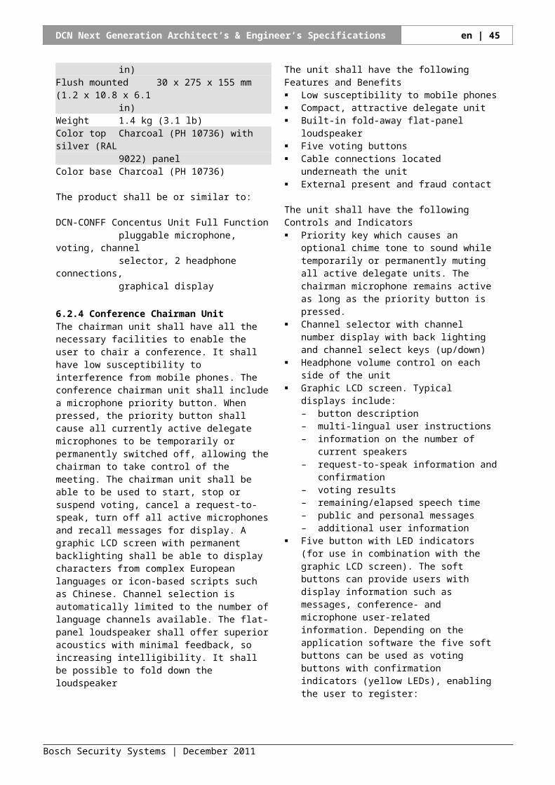
DCN Next Generation Architect’s & Engineer’s Specifications en | 45
DCN-MICL Pluggable Microphone Long stem
6.4.8 Rims for Discussion UnitsA rim shall complete the discussion units. A variety of rims with different finishes shall be are available to allow matching with any interior.
The unit shall have the following Technical SpecificationsMechanicalMounting Click and fit on any discussion unitColor
Silver (RAL 9022) high glossSilver (RAL 9022)Charcoal (PH 10736)High gloss metalSemi gloss metal
The product shall be or similar to:DCN-DISR-SRH Set of 10 rims for Discussion unit
Silver, High glossDCN-DISR-SR Set of 10 rims for Discussion unit
Silver DCN-DISR-D Set of 10 rims for Discussion unit
DarkDCN-DISRM-H Set of 10 rims for Discussion unit
Metal, High glossDCN-DISRM-S Set of 10 rims for Discussion unit
Metal, Semi gloss
6.4.9 Buttons for Chairman Discussion UnitThe buttons for Chairman Discussion Units shall replace the single microphone button on a Discussion unit when used in chairman mode. These buttons shall also be useable for the Discussion unit in Auxiliary control mode
The unit shall have the following Technical SpecificationsMechanicalMounting Click and fit on any Discussion unitColor Silver (RAL 9022)
The product shall be or similar to:DCN-DISBCM 10 sets of buttons for Chairman Discussion unit
6.4.10Buttons for Dual Use Discussion UnitButtons for Dual Use Discussion Units shall replace the single microphone button on a discussion unit when used in dual delegate mode.
The unit shall have the following Technical SpecificationsMechanicalMounting Click and fit on any Discussion unitColor Silver (RAL 9022)
The product shall be or similar to:
DCN-DISBDD 10 sets of buttons for Dual use Discussion unit
6.4.11 Battery Pack for Wireless Discussion Unit
The lithium-ion battery is the power source for the wireless discussion units. The unit shall have the following characteristics: It allows up to 20 hours typical use from a full
charge, with listen to speech ratio of 80/20. It shall be fully charged from empty in 3 hours. It shall have lithium-ion cells to avoid charge
degradation. It shall provide maximum flexibility for scheduling
recharges (no need to fully discharge batteries before recharging).
It shall have a built-in microprocessor to control charging current and prevent overloading.
The unit shall have the following Controls and Indicators: push-to-test button and 5 charge capacity LEDs, to
test remaining capacity
The unit shall have the following Technical SpecificationsElectricalOutput Voltage 7.2VDCCapacity 4800 mAhOutput power 2 x 15 mW/32 ohm
MechanicalDimensions (Height x Width x Depth) = 61.5 x 136
x 22 mm (2.4 x 5.5 x 0,9 in)Weight 215 g (0.47 lb)Color Charcoal (PH 10736)
The product shall be or similar to:Bosch DCN-WLIION-D BatteryPack
6.4.12Power Adaptor for Wireless Discussion Unit
The power supply enables wireless discussion units to be used without a battery.
The unit shall have the following Technical SpecificationsElectricalInput Voltage 100-240 VAC (50 – 60 Hz), 150mAOutput Voltage 9VDC (500mA)
MechanicalDimensions (Height x Width x Depth) = 65.5 x 57
x 28 mm (2.56 x 2.24 x 1.1 in)Weight 100 g (0.22 lb)
The power product shall or similar to:DCN-WPS Power Supply for Wireless Discussion unit
Bosch Security Systems | December 2011
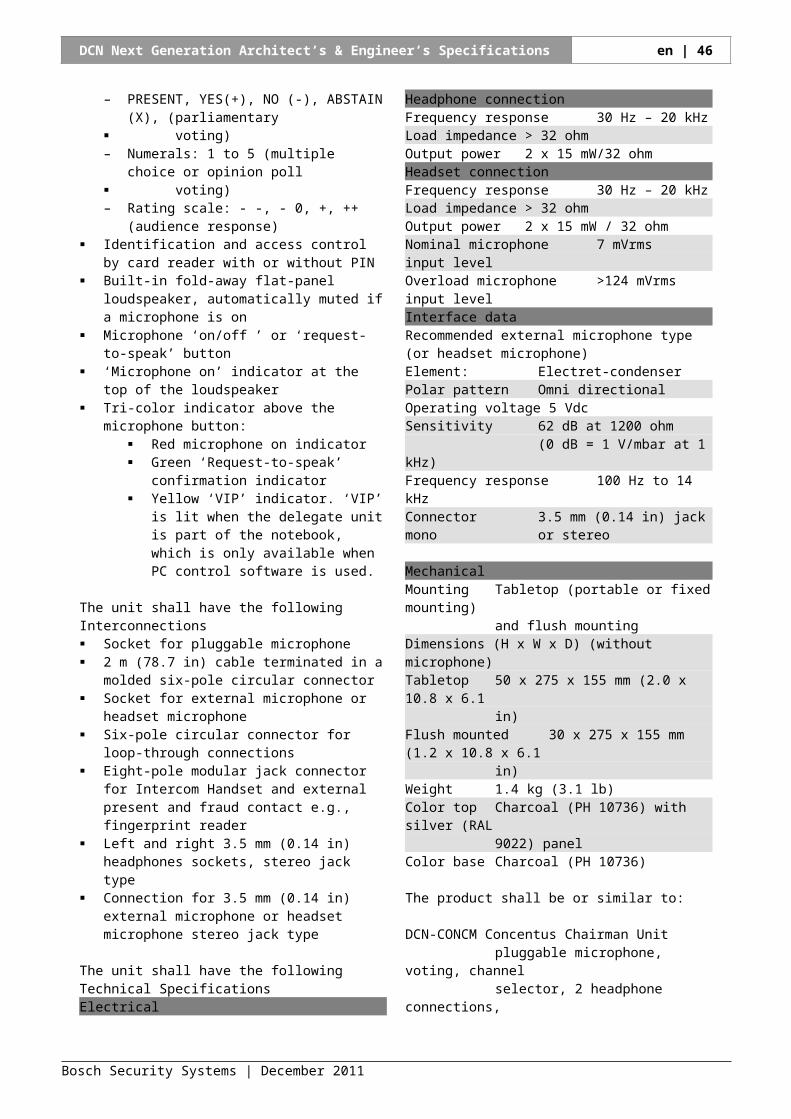
DCN Next Generation Architect’s & Engineer’s Specifications en | 46
6.4.13Wireless Battery ChargerThe charger is used to charge batteries of wireless discussion units.
The unit shall offer the following features and benefits: Simultaneous charging of up to 5 lithium-ion battery
packs It shall have loop-through mains connector, to
cascade more chargers to one mains socket It shall have an auto-ranging PSU, from 100 – 240
VAC The charging status of each pack is shown on
individual charge capacity indicator LEDs Mains power indicator LED The unit is suitable for tabletop use, or can be wall
mounted with a bracket
The unit shall have the following Technical SpecificationsElectricalSupply Voltage 100-240 VAC (50 – 60 Hz)Maximum power consumption 190W
MechanicalDimensions (H x W x D) 340 x 195 x 82 mm (13.4 x
7.6 x 3.2 in)Weight 1.4 kg (3.08 lb)Color Charcoal (PH 10736)
The product shall be or similar to:DCN-WCH05 Wireless Battery Charger
6.4.14Flight Case for WCCU and WAPThis flight case is used for transportation and storage of a central control unit and a wireless access point.
The product shall comply with the following characteristics: It shall have a robust construction with reinforced
corners It shall have a shaped interior to hold a central
control unit, a wireless access point and a network cable
It shall have a dividing foam partition, when removed the flight case can hold two central control units
The unit shall have the following Technical SpecificationsMechanicalDimensions (H x W x D) 480 x 510 x 295 mm (18.9 x
20.1 x 11.46 in)Weight 6 kg (13.2 lb)Color Light grey
The product shall be or similar to:DCN-WFCCCU Flight Case for Wireless CCU and WAP
6.4.15Roller Case for 10 wireless discussion units
This roller case is used for transportation and storage of 10 wireless discussion units and two wireless battery chargers.
The unit shall comply with the following characteristics: It shall have a robust construction with reinforced
corners It shall have a shaped interior to hold 10 wireless
discussion units, including short or long microphones
It shall also holds 2 battery chargers and 10 batteries It shall have fitted wheels for easily transportation
The unit shall have the following Technical SpecificationsMechanicalDimensions (H x W x D) 695 x 765 x 500 mm (27.4 x
30.1 x 19.7 in)Weight 26.4 kg (58.2 lb)Color Light grey
The product shall be or similar to:DCN-RCWD10 Roller Case for 10 Wireless Discussion Units
6.4.16Flight Case for 10 wireless discussion units
This flight case is used for transportation and storage of ten wireless discussion units and two wireless battery chargers.
The product shall comply with the following characteristics: It shall have a robust construction with reinforced
corners It shall have a shaped interior to hold 10 wireless
discussion units It shall hold 10 pluggable microphones, short or long It shall also holds 2 battery chargers and 10 batteries It shall have two fitted wheels and an extra handgrip
for easily transportation
The unit shall have the following Technical SpecificationsMechanicalDimensions (H x W x D) 820 x 500 x 300 mm (32.3 x
19.7 x 12 in)Weight 13.8 kg (30.4 lb)Color Light grey
The product shall be or similar to:DCN-FCWD10 Flight Case for 10 Wireless Discussion Units
Bosch Security Systems | December 2011
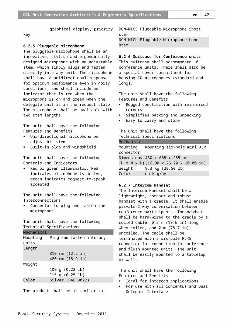
DCN Next Generation Architect’s & Engineer’s Specifications en | 47
7 Interpretation and Language Distribution Equipment
7.1 Interpreter DeskThe interpreter desk shall be a single-user interpreter desk with a stylish and modern design. It shall fully conform to internationally agreed standards. Clear positioning per functional area of the desk controls shall allow intuitive operation without mistakes. The interpreter desk shall be available with a light- and a dark-colored base
The product shall have the following Features and Benefits Low susceptibility to mobile phones Ergonomic design and features for visually impaired Up to 31 interpretation channels and the original
floor language with an audio bandwidth of 20 kHz A graphic LCD with backlighting for bright
information display under low light level conditions 5 pre-select keys for relay languages with activation
indication at the display Microphone push button with a red or green
illuminated ring Light- or dark-colored base
The product shall have the following Controls and Indicators A and B output channel with status and selection
indication at the display All channels have channel number, language names
and quality level indicated at the display Ergonomic design and features for visually impaired
such as a pimple at the middle button and beeps to indicate microphone on / off and double relay selected
Built-in loudspeaker with language channel selector Speech timer to indicate elapsed time of
interpretation Speak slowly facility to alert the current speaker to
slow down Help request to an operator or usher Booth telephone and intercom indicator A maximum of six desks can be installed in per
booth Table top and flush mountable Pluggable microphone Automatic headset selection when headset connected Easy programming via menus on the display after
entering the programming mode Microphone key with surrounding red “on-air”
indicator and green for “booth not in use” Mute key Help key Slow (speak slowly) key
Operator and chairman intercom call keys (for future use)
Message key with yellow LED indicator (for future use)
Telephone and Intercom call yellow LED indicators A and B channel engaged yellow LED indicators Rotary step control for channel settings (and other
functions)Pressing this button sets the selection to the first available channel
LCD with backlighting showing selected and activated output channel with channel numbers and abbreviated language names
Loudspeaker rotary volume control Headphone rotary volume control Headphone rotary bass and treble tone controls Beep on/off key Five Relay language pre-select keys Floor/auto-relay key with green LED indicators Rotary step control (same as for speaking section) to
select the relay languages for the relay pre-select keys and the loudspeaker channel. Pressing this button sets the selection to the first available channel
LCD with backlighting, showing selected relay language with channel numbers, abbreviated names and quality indicators. Also the selected loudspeaker channel with abbreviated name is shown
The product shall have the following Interconnections Six-pole microphone socket Headphone or headset connector five-pole 180° Din
type socket wired according to IEC 574-3) 6.3 mm (0.25 in) and 3.5 mm (0.14 in) stereo jack
headphone connectors 2 m 78.8 in) cable with molded six-pole circular
connector Six-pole circular socket for loop-through connection
to the network Eight-pole modular jack connector for connection to
booth telephone, intercom and booth on-air sign
The product shall have the following Technical SpecificationsElectricalHeadphone connectionFrequency response 30 Hz – 20 kHzLoad impedance > 32 ohmOutput power 2 x 30 mW/32 ohmHeadset connectionFrequency response 30 Hz – 20 kHzLoad impedance > 32 ohmOutput power 60 mW / 32 ohmNominal microphone 7 mVrmsinput levelOverload microphone >124 mVrmsinput level
MechanicalMounting Free-standing or mounted on a table
Bosch Security Systems | December 2011
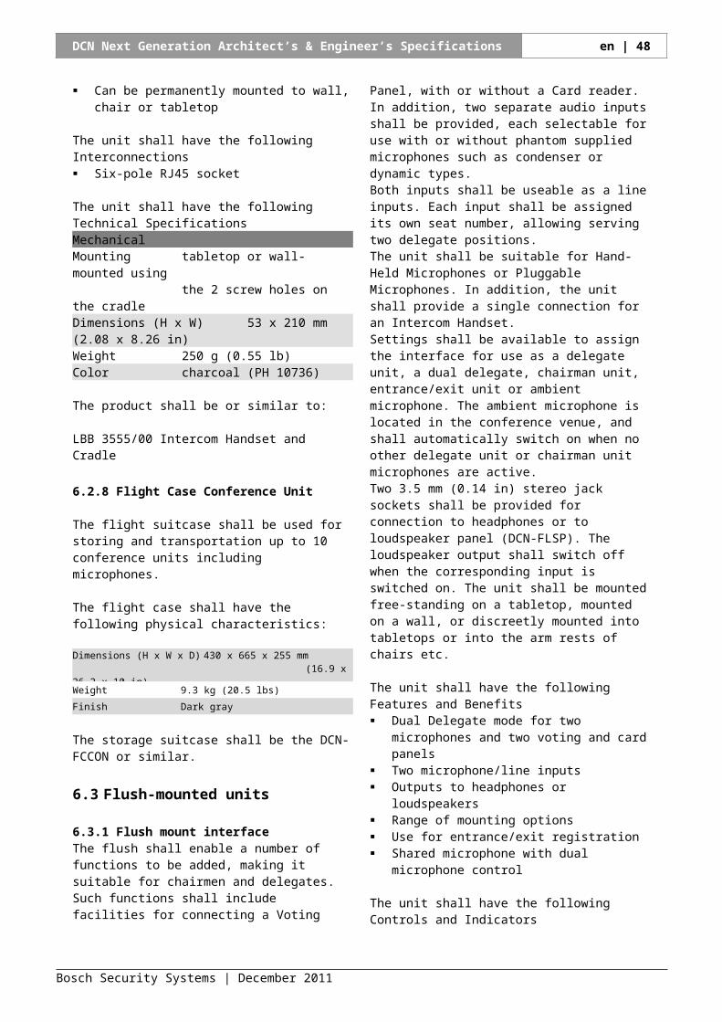
DCN Next Generation Architect’s & Engineer’s Specifications en | 48
Dimensions 82 x 330 x 170 mm (3.2 x(H x W x D) 13 x 6.7 in) (with microphone)Slope 25 degreesWeight 1.3 kg (2.87 lbs)Color top Silver (RAL 9022)Color base
Light Gray (RAL 000 7500)Color base
Charcoal (PH 10736)
The product shall be or similar to:
DCN-IDESK-L Interpreter Desk with light baseDCN-IDESK-D Interpreter Desk with dark base
7.2 Interpreter HeadphonesThe interpreter headphones shall be lightweight, dynamic headphones.
The product shall have the following Features and Benefits Replaceable ear pads
The product shall have the following Interconnections 1.5 m (59.0 in) cable terminated with a 6.3 mm (0.25
in) stereo jack plug
The product shall have the following Technical SpecificationsElectricalImpedance 2 x 720 ohmFrequency response 250 Hz to 13 kHz (-10 dB)Power handling capacity 200 mWSensitivity (1 kHz) 97 dB SPL/earpiece at0
dBV/system96 dBSPL/earpiece at1 mW/earpiece
MechanicalWeight 78 g (0.17 lb)Color Black/gray
The product shall be or similar to:
LBB 9095/30 Interpreter HeadphonesLBB 9095/50 Set of 25 pairs of replacement ear pads
Suitcase for interpreter deskThe suitcase for the interpreter desk shall accommodate 2 desks, 2 microphones and accessories such as headsets, headphones and tabletop reading-lights.
The product shall have the following Features and Benefits Rugged construction with reinforced corners Simplifies packing and unpacking Easy to carry and store
The product shall have the following Technical Specifications
MechanicalDimensions (H x W x D) 235 x 530 x 385 mm
(9.3 x 20.9 x 15.2 in)Weight (empty) 6 kg (13 lbs)Color Dark Gray
7.3 Channel Selector unitThe channel selector unit shall be a compact and stylish single-user audio channel selector for listening by headphone. It shall provide a choice of up to 32 high-quality audio channels used for distribution of interpretation and floor channels.
The product shall have the following Features and Benefits No audio output until the headphone is connected. Automatically adapts to available channels Stylish and modern design Built-in “Silent” function; no audio output until one
of the keys has been pressed to eliminate audible noise from the headphones when not in use.
Upon insertion of a headphone the default “floor” channel (channel 0) is selected with a comfortable headphone volume and the dimmed backlighting is activated.
Flush mountable in tabletops, on top or at the front, or in arm rests of seats.
Two push-buttons (up/down) for channel selection Two push-buttons (up/down) for headphone volume
control Backlit 2-digit LCD for channel number indication
The product shall have the following Interconnections 3.5 mm (0.14 in) mm stereo jack headphone
connector Connector for external headphone 2 m (78.7 in) cable with a molded six-pole circular
connector Six-pole circular connector for loop-through
interconnection
The product shall have the following Technical SpecificationsElectricalFrequency response 30 Hz – 20 kHzHeadphone load > 32 ohm < 1k ohmimpedanceOutput power 2 x 15 mW/32 ohm
MechanicalMounting Flush mountedDimensions (H x W x D) 40 x 100 x 100 mm
(1 .6 x 3.9 x 3.9 in)Weight 0.3 kg (0.66 lb)Color Silver (RAL 9022)
The product shall be or similar to:
DCN-FCS Channel Selector unit for 32 channels
Bosch Security Systems | December 2011
DCN Next Generation Architect’s & Engineer’s Specifications en | 49
7.4 Table Top HousingsThis housing shall enable the flush mounted panels to be used in tabletop applications. The panel shall simply click into place in the housing. It shall be for use with the voting unit, but it can also be used for other flush mounted unit such as the channel selector unit.Provision shall be made so for permanent applications, the housing can be fixed to the tabletop.
The unit shall have the following Technical SpecificationsMechanicalMounting free-standing or fixed on the table topDimensions 40 x 100 x 82 mm(H x W)Weight 243 gColor Charcoal (PH 10736)
The product shall be or similar to:
DCN-TTH Set of 10 Table Top Housings
7.5 Lightweight Stereo Headphones
Lightweight stereo headphones shall offer high quality sound reproduction.
The product shall have the following Features and Benefits Replaceable ear pads Separate available solid washable ear pads
The product shall have the following Interconnections 1 .3 m (51.2 in) cable terminated with 3.5 mm (0.14
in) angled stereo jack plug
The product shall have the following Technical SpecificationsElectricalImpedance 32 ohm per earpieceAudio frequency response 50 Hz to 20 kHz (-10 dB)Power handling capacity 50 mWSensitivity (1 kHz) 98 dB SPL/earpiece at
1 mW/earpiece
MechanicalWeight 70 g (0.16 lb)Finish Charcoal (PH 10736)
with silver
The product shall be or similar to:
LBB 3443/00 Lightweight Stereo HeadphonesLBB 3443/50 Set of 100 pairs of replacement ear padsHDP-LWSP Set of 50 pairs solid ear pads
7.6 Under-the-Chin Stereo HeadphonesThe product shall have the following Features and Benefits
Ergonomic design for use under the chin Replaceable ear tips
The product shall have the following Interconnections 1 .2 m (47.3 in) cable terminated with 3.5 mm (0.14
in) angled stereo jack plug
The product shall have the following Technical SpecificationsElectricalImpedance 150 ohm per earpieceAudio frequency response 50 Hz to 5 kHz (-10 dB)Power handling capacity 60 mWSensitivity (1 kHz) 107 dB SPL/earpiece at
1 mW/earpiece
MechanicalWeight 33 g (0.07 lb)Finish Black
The product shall be or similar to:
LBB 3441/10 Under-the-Chin Stereo HeadphonesLBB 3441/50 Set of 1.000 replacement ear tips
7.7 Single EarphoneThe product shall have the following Features and Benefits Ergonomic design for use under the chin Replaceable ear tips
The product shall have the following Interconnections 1 .2 m (47.2 in) cable terminated with 3.5 mm (0.14
in) stereo jack plug
The product shall have the following Technical SpecificationsElectricalImpedance 32 ohmAudio frequency response 100 Hz to 5 kHz (-10 dB)Power handling capacity 5 mWSensitivity (1 kHz) 114 dB SPL/earpiece at 1
mW/earpiece
MechanicalWeight 25 g (0.06 lb)Finish Dark gray
The product shall be or similar to:
LBB 3442/00 Single Earphone
7.8 High Quality Dynamic Headphones
This high quality dynamic microphone shall be a durable dynamic headphones offering high-quality sound reproduction.
Bosch Security Systems | December 2011
DCN Next Generation Architect’s & Engineer’s Specifications en | 50
The product shall have the following Features and Benefits Replaceable ear pads
The product shall have the following Interconnections 1 .2 m (47.2 in) cable terminated with 3.5 mm (0.14
in) stereo jack plug
The product shall have the following Technical SpecificationsElectricalImpedance 720 ohm per earpieceAudio frequency response 250 Hz to 13 kHz (-10 dB)Power handling capacity 200 mWSensitivity (1 kHz) 96 dB SPL/earpiece at
1 mW/earpiece
MechanicalWeight 25 g (0.06 lb)Finish Dark gray
The product shall be or similar to:
LBB 3015/04 High Quality Dynamic HeadphonesLBB 9095/50 Set of 25 pairs of replacement ear pads
7.9 Induction Loop Neckband
The induction loop neckband shall be suitable for use with the receivers.
The induction loop neckband shall have the following physical and electrical characteristics:
Connection 0.9 m (3 ft) cable with 3.5 mm (0.14 in) gold-plated jack plug
Impedance 28 ohms at 1 kHz
Magnetic Field Strength 100 mA/m 15 cm (6 in) above loop at 85 μW at 1 kHz input (IEC 60118-4)
Weight 45 g (0.10 lb)
Finish Charcoal with silver
The induction loop neckband shall be the HDP-ILN or similar.
7.10 Flight Case
The flight suitcase shall be used for storing and transportation up to 2 interpreter desks.
The flight case shall have the following physical characteristics:
Dimensions (H x W x D) 235 x 530 x 385 mm (9.3 x 20.9 x 15.2 in)
Weight 6 kg (13 lbs)
Finish Dark gray
The storage suitcase shall be the DCN-FCIDSK or similar.
Bosch Security Systems | December 2011
DCN Next Generation Architect’s & Engineer’s Specifications en | 51
8 Central Control Equipment
8.1 Basic Central Control UnitThe basic central control unit (CCU) shall include features for controlling delegate microphones, distributing simultaneous interpretation and conducting voting sessions, all without an operator.
The product shall have the following Features and Benefits IF design award Control for up to 245 wired Contribution units Control facilities for an unlimited number of channel
selectors 2 x 32 high-quality audio channels Basic microphone management facilities Four operational microphone modes:
Open: microphone button control with request-to-speak (Auto)
Override: microphone button with override of activated microphones (FIFO)
Voice: voice activated microphones Push-to-talk (push and hold button to speak)
Number of open microphones between 1 and 4 Basic voting control for parliamentary voting
procedure. Delegates can register ‘Present’, ‘Yes’, ‘No’ and ‘Abstain’. The Concentus Chairman unit can start, stop and suspend the voting. The total results can be displayed on hall displays and on the LCD screens of the units. Also included is a page function, which activates a voting tone. The chairman can use this tone to indicate that a voting round is about to start.
Basic simultaneous interpretation function with as many as 31 language channels plus one floor channel
Basic intercom function with a function to assign intercom operator and intercom chairman (both can be called from the interpreter desk)
Automatic camera control 2 audio line inputs and 2 audio line outputs Adjustable sensitivity for the audio inputs Adjustable level for the audio outputs Audio insertion facility to connect external audio
processing devices or telephone couplers Configuration of CCU and system via a display and
a single rotary push button Each CCU can be assigned a unique name by the
installer for easy identification VU meter readings to monitor audio inputs and
audio outputs. The audio can be monitored using headphones
19” (2U) housing for table top or rack mounting Handgrips for easy transportation 19” rack mounting brackets, detachable feet and
mounting accessories included System installation and user instruction on DVD
ROM
The product shall have the following Controls and Indicators Power on/off switch at the
front 2 x 16 Character LCD display
at front for status information and CCU configuration
Rotary control at front to navigate through the LCD menus
Three red LED overload indicators for the DCN network outputs at the rear
The product shall have the following Interconnections Euro mains socket with built-in fuse, matching
mains cable (1.7 m [5.58 ft]) included Three DCN outlet sockets including locking facility
for connection of units Two stereo Cinch unbalanced audio line inputs One three-pole XLR balanced audio line output Two stereo Cinch unbalanced audio line outputs 1 x headphone output 3.5 mm (0.14 in) stereo One Ethernet connection for Control PC or Open
Interface One RS-232 serial data connector for Camera
control
The product shall have the following Technical SpecificationsElectricalSupply voltage 100/240 Vac 50-60 HzPower consumption 295 WDCN system supply 40 VDC, max 85 W per DCN
socketTotal supply power 255 WRS-232 connection nine-pole Sub-D female socketFrequency response 30Hz – 20 kHz (-3dB at
nominal level)THD at nominal level < 0.5 %Cross talk attenuation > 85 dB at 1 kHzDynamic range > 90 dBSignal–to-noise ratio > 87 dBAAudio inputsCinch nominal input 24 dBV (+/- 6dB)Cinch maximum input +0 dBVAudio outputsXLR nominal output 12 dBV (+6/- 24 dB)XLR maximum output +12 dBVCinch nominal output 24 dBV (+6/- 24 dB)Cinch maximum output +0 dBV
MechanicalMounting Free-standing or mounted
in a 19”-rackDimensions (H x W x D) 88 x 483 x 350 mm
(with brackets, withoutfeet)92 x 440 x 350 mm(without brackets, with
Bosch Security Systems | December 2011
DCN Next Generation Architect’s & Engineer’s Specifications en | 52
feet)Weight 7.9 kgColor Charcoal (PH 10736) with
silver
The product shall be or similar to:DCN-CCUB2 Basic Central Control Unit
8.2 Central control unitIn combination with a PC, the central control unit (CCU) shall bring greater sophistication to conference control. Users shall be able to access an extensive range of software modules, each with a specific function in controlling and monitoring a conference. These modules shall expand the capacity to manage a conference. In the event of PC failure, this Central Control Unit shall revert to its stand-alone operation mode, enabling the conference to proceed.
The product shall have the following Features and Benefits IF design award Control for up to 245 wired and 245 wireless
Contribution units Control facilities for an unlimited number of channel
selectors 2 x 32 high quality audio channels Optical network for coupling the CCU to Integrus
transmitter for Infra Red languages distribution, Wireless Access Point for wireless discussion units and to Audio Expanders and Cobranet Interfaces to allow a variety of audio contribution and distribution facilities • Optical network designed for redundant cabling. Can be either single branch or redundant loop
Basic microphone management facilities Four operational microphone modes:
Open: microphone button control with request-to-speak (Auto)
Override: microphone button with override of activated microphones (FIFO)
Voice: voice activated microphones Push-to-talk (push and hold button to speak)
Number of open microphones between 1 and 4 Basic voting control for parliamentary voting
procedure. Delegates can register ‘Present’, ‘Yes’, ‘No’ and ‘Abstain’. The Concentus Chairman unit can start, stop and suspend the voting. The total results can be displayed on hall displays and on the LCD screens of the units. Also a page function is included which activates a voting tone. With this tone the chairman can indicate that a voting round is about to start.
Basic simultaneous interpretation function with as many as 31 language channels plus one floor channel
Basic intercom function with function to assign intercom operator and intercom chairman (both can be called from the interpreter desk)
Automatic camera control
Extended conference facilities when using control PC software or remote controllers
2 audio line inputs and 2 audio line outputs Adjustable sensitivity for the audio inputs Adjustable level for the audio outputs Audio insertion facility to connect external audio
processing devices or telephone couplers Configuration of CCU and system via a display and
a single rotary push button Each CCU can be assigned a unique name by the
installer for easy identification VU meter readings to monitor audio inputs and
audio outputs. The audio can be monitored using a headphone
19” (2U) housing for table top or rack mounting Handgrips for easy transportation 19” rack mounting brackets, detachable feet and
mounting accessories included System installation and user instruction on DVD
ROM
The product shall have the following Controls and Indicators Power on/off switch at front 2 x 16 Character LCD display at the front for status
information and CCU configuration Rotary control at the front to navigate through the
LCD menus Three red LED overload indicators for the DCN
network outputs at the rear Two red LED overload indicators for the optical
connections at the rear
The product shall have the following Interconnections Euro mains socket with built-in fuse, matching 1.7 m
mains cable ( (66.9 in) included Three DCN outlet sockets including locking facility
for connection of units Two optical network connections for connection of
Integrus transmitters, various Audio Expanders, CobraNet interfaces and Wireless Access Point
Two three-pole XLR balanced audio line inputs with optional galvanic separation.
Two stereo Cinch unbalanced audio line inputs Two three-pole XLR balanced audio line output with
galvanic separation. Two stereo Cinch unbalanced audio line outputs 1 x headphone output 3.5 mm (0.14 in) stereo One Ethernet connection for Control PC, Open
Interface or slave CCU One RS-232 serial data connectors for controlling
cameras
The product shall have the following Technical SpecificationsElectricalSupply voltage 100/240 Vac 50-60 HzPower consumption 295 WDCN system supply 40 VDC, max 85 W per DCN
socketOptical network supply 40 VDC, max 85 W
Bosch Security Systems | December 2011
DCN Next Generation Architect’s & Engineer’s Specifications en | 53
Total supply power 255 WRS-232 connection 2 x nine-pole Sub-D female
socketFrequency response 30Hz – 20 kHz (-3dB at
nominal level)THD at nominal level < 0.5 %Cross talk attenuation > 85 dB at 1 kHzDynamic range > 90 dBSignal–to-noise ratio > 87 dBAAudio inputsXLR nominal input 12 dBV (+/- 6dB)XLR maximum input +12 dBVCinch nominal input 24 dBV (+/- 6dB)Cinch maximum input +0 dBVAudio outputsXLR nominal output 12 dBV (+6/- 24 dB)XLR maximum output +12 dBVCinch nominal output 24 dBV (+6/- 24 dB)Cinch maximum output +0 dBV
MechanicalMounting Free-standing or mounted
in a 19”-rackDimensions (H x W x D) 88 x 483 x 350 mm
(with brackets, withoutfeet)92 x 440 x 350 mm(without brackets, withfeet)
Weight 7.9 kgColor Charcoal (PH 10736)
with silver
The product shall be or similar to:DCN-CCU2 Central Control Unit
8.3 Wireless Access PointThe wireless access point (WAP) shall link the central control unit with wireless discussion units.
The wireless access point shall offer the following features and benefits: It shall have secure wireless communication between
the WAP and the wireless discussion units is in the 2.4 GHz band, which is license-free worldwide.
To ensure security, the communication with wireless discussion units shall be digitally protected.
It shall be able to cover at least an area of 900 square meters (10.000 square ft).
It shall be powered and it shall communicate with the central control unit via a single network.
It shall have two optical network connectors, so it can be used in a single branch or redundant loop configuration.
It shall be possible to mount it to a wall, ceiling, or floor-stand by using the universal bracket.
It shall have LED indicators to show the status of the wireless discussion system.
The product shall have the following Technical Specifications
MechanicalMounting Free-standing or mounted
in a 19”-rackDimensions 59 x 284.5 x 201 mm(H x W x D) (2.3 x 11.2 x 7.9 in)
(with bracket)Weight 907 g (2 lb) with bracket
643 g (1.4 lb) without bracketColor Light grey (RAL 000 7500)
The product shall be or similar to:DCN-WAP Wireless Access Point
8.4 Extension Power SupplyThe Extension Power Supply unit shall be used in combination with a CCU to supply extra power to the network.
The product shall have the following Features and benefits Easy to connect to the network Maximum supply power of 255 W Installable at any convenient point in the system
cabling due to its built-in network splitter Using loop-through cabling Switches on automatically when the CCU is
switched on All outputs are protected against short circuit Freestanding on a tabletop or mounted in a 19” rack
The product shall have the following Controls and Indicators “Power on” LED indicator Three indicators to indicate network outlet overload
(red LEDs)
The product shall have the following Interconnections Euro-mains socket with built-in fuse holder, mains
cable 1.7 m (66.9 in) included 2 m (78.7 in) DCN cable with molded six-pole
circular connector Six-pole circular socket for loop-through connection
to the network Three outlet sockets for connection of units, plus
extension power supplies. Each socket is protected against short-circuit (3 x six-pole circular sockets)
The product shall have the following Technical SpecificationsElectricalSupply voltage 105, 115, 125, 220, 230,
240 Vac., 50/60 HzPower consumption 350 WSystem supply 40 VDC, max 85W per socket
MechanicalMounting Free-standing on a table top
Bosch Security Systems | December 2011
DCN Next Generation Architect’s & Engineer’s Specifications en | 54
or mounted in a 19” rack unit(requires 2U, _19” width)
Dimensions 100 x 220 x 308 mm(H x W x D) (3.9 x 8.7 x 12.1 in)Weight 8.3 kg (18.3 lbs)Color cabinet Light gray (PH 10736)Color handles Dark gray (PH 10736)
The product shall be or similar to:
DCN-EPS Extension Power SupplyDCN-EPS-UL Extension Power Supply UL/CSA
intended for North-America region
8.5 Digital Audio ExpanderThe digital audio expander shall contribute digital audio to and distribute digital audio from the system.
The product shall have the following Features and Benefits IF design award Room coupling facility Versatile audio distribution facility Optical network for coupling to the CCU AES/EBU or SPDIF Sample-rate converters (8 – 96 kHz) Automatic Gain Control Designed for redundant network cabling. The
network can be either single branch or redundant loop.
Four audio channels in for floor and interpretation channels
Four audio channels out for floor and interpretation channels (16-bit 44.1 kHz)
Flexible routing of floor and interpretation channels Configuration of the Digital Audio Expander via a
display and a single rotary push button Each Digital Audio Expander can be assigned a
unique name by the installer for easy identification VU meter readings to monitor audio inputs and
audio outputs. The audio can be monitored using headphones
19” (2U) housing for table top or rack mounting Handgrips for easy transportation 19” rack mounting brackets, detachable feet and
mounting accessories included Unit is powered from the network
The product shall have the following Controls and Indicators 2 x 16 Character LCD display for status display and
configuration of the Audio Expander Rotary control at the front to navigate through the
LCD menus
The product shall have the following Interconnections Two optical network connections for connecting to
CCU Two 3-pole XLR AES/EBU stereo inputs for 2 audio
channels per input
Two Cinch SPDIF stereo inputs for 2 audio channels per input
Two 3-pole XLR AES/EBU stereo outputs for 2 audio channels per output
Two Cinch SPDIF stereo outputs for 2 audio channels per output
8 x control inputs to enable audio inputs and audio outputs
5 x control outputs to indicate channel engaged state • 1 x headphone output 3.5 mm (0.14 in) stereo
The product shall have the following Technical SpecificationsElectricalSupply voltage 24 – 48 VdcPower consumption 6 WFrequency response 30 Hz – 20 kHzTHD at nominal level < 0.5 %
MechanicalMounting Free-standing or mounted
in a 19”-rackDimensions (H x W x D) 88 x 483 x 350 mm
(with brackets, withoutfeet)92 x 440 x 350 mm(without brackets, withfeet)
Weight 6 kgColor Charcoal (PH 10736)
with silver
The product shall be or similar to:PRS-4DEX4 Digital Audio Expander
8.6 Audio ExpanderThe audio expander shall contribute audio to and distribute audio from the system.
The product shall have the following Features and Benefits IF design award Room coupling facility Versatile audio distribution facility Optical network for coupling to the CCU Designed for redundant network cabling. The
network can be either single branch or redundant loop
Four audio line inputs (of which 2 can be configured as microphone input) for floor and interpretation channels
Four audio line outputs for floor and interpretation channels
Flexible routing of floor and interpretation channels Adjustable sensitivity for the audio inputs Adjustable level for the audio outputs Configuration of the Audio Expander via a display
and one single rotary push button
Bosch Security Systems | December 2011
DCN Next Generation Architect’s & Engineer’s Specifications en | 55
Each Audio Expander can be assigned a unique name by the installer for easy identification
VU meter readings to monitor audio inputs and audio outputs. The audio can be monitored using a headphone
19” (2U) housing for table top or rack mounting Handgrips for easy transportation 19” rack mounting brackets, detachable feet and
mounting accessories included The unit is powered from the network
The product shall have the following Controls and Indicators 2 x 16 Character LCD display for status display and
configuration of the Audio Expander Rotary control at the front to navigate through the
LCD menus
The product shall have the following Interconnections Two optical network connections for connecting to
the CCU Four three-pole XLR balanced audio line inputs with
galvanic separation Four stereo Cinch unbalanced audio line inputs Four three-pole XLR balanced audio line output with
galvanic separation Four stereo Cinch unbalanced audio line outputs 8 x control inputs to enable audio inputs and audio
outputs 5 x control outputs to indicate channel engaged state 1 x headphone output 3.5 mm (0.14 in) stereo
The product shall have the following Technical SpecificationsElectricalSupply voltage 24 – 48 VdcPower consumption 7.6 WFrequency response 30 Hz – 20 kHz (-3dB at
nominal level)THD at nominal level < 0.5 %Cross talk attenuation > 85 dB at 1 kHzDynamic range > 90 dBSignal–to-noise ratio > 87 dBAAudio line inputsXLR nominal input 0 dBV (±6 dB)XLR maximum input + 12 dBVCinch nominal input 12 dBV (±6 dB)Cinch maximum input + 0 dBVAudio microphone inputsNominal input 57 dBV (±6 dB)Maximum input 26 dBVPhantom supply 12 V ± 1 V @ 15 mAAudio line outputsXLR nominal output 12 dBV (+ 6/- 24 dB)XLR maximum output + 12 dBVCinch nominal output 24 dBV (+ 6/- 24 dB)Cinch maximum output + 0 dBV
MechanicalMounting Free-standing or mounted
in a 19”-rack
Dimensions 88 x 483 x 350 mm(H x W x D) (with brackets, without
feet)92 x 440 x 350 mm(without brackets, withfeet)
Weight 6 kg (13 lbs)Color Charcoal (PH 10736)
with silver
The product shall be or similar to:LBB 4402/00 Audio Expander
8.7 Cobranet InterfaceThe Cobranet Interface shall interface audio from the conference system to a CobraNet network using standard Ethernet networks.
The product shall have the following Features and Benefits IF design award Room coupling facility Versatile audio distribution facility CobraNet compatible using Ethernet Optical network for coupling to the CCU Automatic Gain Control Designed for redundant network cabling. The
network can be either single branch or redundant loop.
Four audio inputs for floor and interpretation channels
Four audio outputs for floor and interpretation channels
Flexible routing of floor and interpretation channels Configuration of the Cobranet Interface audio
channel routing via a display and a single rotary push button
Configuration of the Cobranet Interface with software tools included
Each Cobranet Interface can be assigned a unique name by the installer for easy identification
VU meter readings to monitor audio inputs and audio outputs. The audio can be monitored using a headphone.
19” (2U) housing for table top or rack mounting Handgrips for easy transportation 19” rack mounting brackets, detachable feet and
mounting accessories included The unit is powered from the network.
The product shall have the following Controls and Indicators 2 x 16 Character LCD display for status display and
audio channel routing of the Cobranet Interface. Rotary control at front to navigate through the LCD
menus
The product shall have the following Interconnections
Bosch Security Systems | December 2011

DCN Next Generation Architect’s & Engineer’s Specifications en | 56
Two optical network connections for connecting to the CCU.
Two RJ45 Ethernet connectors for the CobraNet. 8 x control inputs to enable audio inputs and audio
outputs 5 x control outputs to indicate channel engaged state 1 x headphone output 3.5 mm (0.14 in) stereo
The product shall have the following Technical SpecificationsElectricalSupply voltage 24 – 48 VdcPower consumption 10.5 WFrequency response 30 Hz – 20 kHzTHD at nominal level < 0.5 %CobraNetPhysical layer EthernetChannels 4 in / 4 out per device. Max
64 on CobraNetCompliance IEEE 802.3Audio transport 16-, 20-, 24-bitSample rate 48 kHzLatency 5.33 ms
MechanicalMounting Free-standing or mounted
in a 19”-rackDimensions 88 x 483 x 350 mm(H x W x D) (with brackets, without feet)
92 x 440 x 350 mm(without brackets, with feet)
Weight 7 kgColor Charcoal (PH 10736)
with silver
The product shall be or similar to:
LBB 4404/00 Cobranet Interface
8.8 Feedback SuppressorThe feedback suppressor shall use a powerful DSP with a patented algorithm to suppress acoustic feedback. It shall eliminate feedback by actively filtering out the unwanted room reverb using an echo-cancellation and de-reverberation algorithm. By adding masked (inaudible) noise to the output signal or by shifting the frequency of the output signal by 5 Hz, the feedback suppressor shall be able to detect the reverb component of the signal and shall remove it before feedback occurs, leaving the original signal intact.
The product shall have the following Features and Benefits Patented feedback suppression algorithm Suppresses feedback before it occurs Automatically adapts to the acoustical situation Up to 12 dB additional gain before feedback occurs Balanced line or microphone input with phantom
supply Second microphone input with automatic mixer
The product shall have the following FunctionsThe adaptive filter shall be able to switch between fast mode and accurate mode. The fast mode shall be used for situations where the microphone position changes over time, like in a discussion system with multiple switching microphones. The accurate mode shall be for situations with a fixed microphone position, such as on a pulpit where the acoustical environment is more stable. The adaptive filter shall allow converging more slowly to suppress the reverb components even more. Depending on the acoustical environment and the chosen mode of operation, up to 12dB of additional gain shall be possible before acoustic feedback occurs.The feedback suppressor shall feature a built-in automatic mixer for the two microphone inputs. In many situations, like on a rostrum, pulpit or conference table, two microphones shall be used to better capture the voice of a moving speaker, although this often increases the risk of acoustic feedback. To counter this, the automatic mixer in the feedback suppressor shall automatically reduce the gain of the microphone with the lowest signal input and increases the gain of the microphone with the highest signal input. This way, it shall ‘track’ the moving speaker for optimum speech intelligibility, and the maximum feedback margin is maintained by keeping the summed gain constant. Even when the feedback suppressor is switched to ‘bypass’, the automatic mixer function shall remain operational.
The product shall have the following Controls and Indicators Power switch Bypass / Active switch with yellow / green LED Calibrate button. To start fast calibration cycle Signal indicators
Overload @ 0 dBFS, red Present @ -40 dBFS, green Auto Mix enabled, green Calibrate, yellow
Certifications and ApprovalsEMC emission acc. to EN 55103-1EMC immunity acc. to EN 55103-2
The product shall have the following Technical SpecificationsElectricalMains voltage 230 Vac/115 Vac, ±10%,
50/60HzMax power consumption 50 VAMax mains inrush current 1 .5A @ 230 Vac / 3A @
115 VacSample rate (fs) 32 kHzFrequency response 125 Hz – 15 kHzDistortion <0.1% @ 1 kHzGain (bypass mode) 0 dB Line, in 24/36/48
dBMic in
Gain (active mode) 0 dB Line in24/36/48 dB Mic in
Bosch Security Systems | December 2011
DCN Next Generation Architect’s & Engineer’s Specifications en | 57
S/N >90 dBSignal delay < 11 msDecorrelator Frequency shift, 5 Hz
upMasked noise
Line / Mic input 1 (3-pin XLR, 5-pin DIN, balanced)Max input level 18 / 6 / -6 dBV Line in
-18 / -30 / -42 dBVMic in
Impedance 10 kohm / 2 kohm(Line / Mic)
CMRR >25 dB (50 Hz-20kHz)
Phantom power 16 V (Mic only,switchable)
Priority control Loop through of pin 4and 5 of DIN
Mic input 2, Mic (3-pin XLR, 5-pin DIN, balanced)Max input level 18 / -30 / -42 dBVImpedance 2 kohmPhantom power 16 V (switchable)Priority control Loop through of pin 4
and 5 of DINLine input 3, Line (Cinch, unbalanced)Max input level 18 / 6 / -6 dBVImpedance 20 kohmLine output 1 (3-pin XLR, balanced)Max output level 18 / 6 / -6 dBV (Line
in) 6 dBV (Mic in)Impedance <100 ohmLine output 2 (Cinch, unbalanced)Max output level 8 / 6 / -6 dBV (Line in)
6 dBV (Mic in)Impedance <100 ohmMic output 3 (5-pin DIN, balanced)Max output level 22 / -34 / -46 dBV
(Line in) 34 dBV (Micin)
Impedance <100 ohmPriority control Loop through of pin 4
and 5 of DIN frominputs
MechanicalDimensions 56 x 430 x 270 mm with
feet, without mountingbrackets19” 1U with mountingbrackets, without feet
Weight 3 kg
EnvironmentalOperating temperaturerange 10°C to +55°CStorage temperaturerange 40°C to +70°CRelative humidity <95%
The product shall be or similar to:
LBB 1968/00 Plena Feedback Suppressor
8.9 ID Card EncoderID card encoder shall be used in combination with the ID Card Encoder software. The ID card encoder shall encode delegate ID cards
The product shall have the following Technical SpecificationsMechanicalDimensions 90x 70 x 16.5 mmWeight 145 g
The product shall be or similar to:
LBB 4157/00 ID Card Encoder
8.10 ID CardsIC cards shall be standard credit-card format ID cards. The ID cards shall be used by delegates to identify them to the conference system.
The product shall have the following Features and Benefits Attractive design Ample space for a name or other
delegate personal information. Clear instructions showing how to
insert the card into a reader.
The product shall have the following Technical SpecificationsMechanicalDimensions (HxW) 85 x 54 mm
The product shall be or similar to:
LBB 4159/00 Set of 100 ID Cards
Bosch Security Systems | December 2011

DCN Next Generation Architect’s & Engineer’s Specifications en | 58
9 Application software
9.1 IntroductionThe application shall be modular and shall support the following operating system: Windows 7 Home Premium (32 or 64 bits) or above.
Any combination of the module shall be possible to activate depending on the required functionality.The software modules shall be protected for copying by a license key.
The software shall be prepared for all languages supported by the Microsoft Windows operating system.
9.2 PC Control SoftwareThe control software shall be the main module and shall be used as a platform on which all other modules run.
The product shall have the following Features and Benefits Meeting and agenda support User management Client server solution. Off-line configuration Multi PC Support for wired and wireless contribution
equipment On screen help facility
Split configuration and operating applications Setting master volume levels Single and multi point control of system installation In-conference warning message when installation
configuration changes or when errors appear User management to assign functionality to
individual system users SQL database to store and retrieve all configuration
data and settings.
The product shall consist of four software components: Server which shall manage, control and monitor the
conference system Configuration application which shall provide
system installation and meeting preparation Operator application which shall provide system
monitoring and meeting control Print application which shall provide printing of
voting results
9.2.1 Server applicationThe server shall have the following Functions Monitor and control of the conference data. It runs on the background and links all applications. SQL database stores all data and settings.
Status report of database connection and system connection.
Error logging for quick diagnostics.
9.2.2 Configuration The configuration application shall be a powerful and effective module for installers and system operators configuring and setting up the system.
The configuration application shall have the following Features and Benefits Easy step-by-step pre-configuration which makes it
exceptionally ergonomic. Off-line system configuration. Administrator user management: defining users and
user groups with group privileges like view- and control rights.
Installer system setup: defining seats and synopticlayouts.
Operator meeting preparation: voting templates, participating delegates, authorizations for each meeting, the agenda, lists of speakers and voting scripts.
System channel and language definition Microphone and channel tests
9.2.3 Operator applicationThe operator application shall be a powerful and effective module for system operators to control the meeting
The operator application shall have the following Features and Benefits Full meeting control. Touch screen optimized. Ribbon technology giving the user a graphical
representation of all main functions, which makes it very intuitive to use.
Functionality depending on user rights and system license.
Synoptic microphone control, voting results, Individual microphone sensitivity control, battery status and signal status.
Ergonomically designed synoptic shapes and shadings help the color-impaired people to distinguish different statuses.
Quick-links to jump instantaneously to configuration application to make adjustment to the pre-configuration.
9.2.4 Print applicationThe print application shall be a powerful and effective module for vote results printing
The print application shall have the following Features and Benefits Automatic print of vote results
Bosch Security Systems | December 2011

DCN Next Generation Architect’s & Engineer’s Specifications en | 59
The product shall be or similar to:
DCN-SW Conference Software Main Module
9.3 Microphone ManagementThe Microphone Management module shall provide the user with a powerful and easy-to-use tool that shall bring all aspects of microphone management to a single point of control.
The product shall have the following Features and Benefits Prepare request-to-speak lists Group and individual speech timers Notebook Various microphone control options Extensive range of options for microphone-related
parameters
The product shall have the following FunctionsMicrophones shall be controlled using the name (or device number) of the delegate. The user shall be able to select microphones for the speakers list (active microphones) or prepare a request list.It shall be possible to give notebook status to delegates, which means they shall not have to join the request list and shall enjoy specific privileges not granted to other delegates. The microphone type shall be specifiable for the notebook. The possibilities shall be: ‘Button’ where delegates activate their microphones
by pressing their microphone buttons. (In this mode, the ‘VIP’ LED of the contribution units is illuminated.)
‘Operator’ where the microphones of active delegates are activated by the operator
‘Voice’ where the microphones of the delegates are voice-controlled
The conference system shall automatically recognize an assigned chairman unit and shall automatically add it to the notebook.
Microphone Management shall offer a number of microphone control options. These options are: Control by operator with request-to-speak list
(manual). Control by operator with request-to-speak list and
response list. Control by delegate with request-to-speak list
(open). Control by delegate with override of other delegate
microphones (first-in, first-out). Control by delegate with voice activation. Control by delegate with Push-To-Talk.
Each mode allows a different level of both operator and delegate microphone control, so all general conferences can be covered. For example, smaller, informal discussions require very little operator microphone control, so a mode such as microphone control by delegate would be ideal. For a full-scale international
conference with hundreds of participants, control by operator with request-to-speak list would be more appropriate. The operator can specify whether one, two, three or four normal delegate microphones can be active simultaneously. It is also possible to specify whether delegates are allowed to cancel requests-to-speak or switch their microphones off. The amount of time delegates are allowed to speak can be defined for the current speaker, response speaker, individual delegates and for delegate groups.
It shall also possible to give delegates additional microphone activation privileges, which means they do not have to join the request list and can enjoy certain other privileges not granted to other delegates. The microphone type must be specified for the notebook. The possibilities shall be: ‘Chair’ for chairman microphones. ‘Button’ where delegates activate their microphones
by pressing their microphone button (in this mode the‘VIP’LED of the contribution units is illuminated).
‘Operator’ where the microphones of more active delegates are activated by the operator.
‘Voice’ where the microphones are voice activated. ‘PTT’ where microphones are activated by using Push-To-Talk.Both DCN Next Generation and DCN Wireless systemsautomatically recognize an assigned chairman unit andwill automatically add it to the notebook.
The product shall be or similar to:
DCN-SWMM Microphone Management
9.4 Delegate DatabaseThe Delegate Database module shall allow users to compile a comprehensive database of information relating to participants at a conference or meeting.
The product shall have the following Features and Benefits Comprehensive database creation for all delegates Re-use of delegate information across meetings Define vote and microphone authorization for each
individual participants
The product shall allow users to compile a comprehensive database of information relating to delegates. During the meeting preparation stage the delegates can be assigned to the meeting as participants. The advantage of this method is that delegates participating in multiple meetings only need to be entered once and can be assigned to any desired meeting without re-entering the same delegate information again.
All information will be entered via the configuration application, before or during conference proceedings. A considerable amount of data can be specified for each conference participant. All delegate specific information
Bosch Security Systems | December 2011

DCN Next Generation Architect’s & Engineer’s Specifications en | 60
like: delegate name, delegate country, delegate group and delegate unit display language, can be re-used and does not need to be re-entered for every meeting. At meeting preparation it is possible to grant or deny authorization to individual delegates in a specific meeting for microphone, and voting use; also the voting weight can be defined.
All delegate information will be input via the configuration application. For some entries (first name, last name) the only restriction is the number of characters entered. For other entries (country, group, etcetera.), the input can easily be selected from a list of options that is presented by the system. This option list is automatically controlled by the system. When the user enters a text it is automatically added to the list.
By defining the correct user rights a delegate information entry PC client can be created. This entry client can be placed at the lobby of a conference hall entrance, where the registration officer can enter delegate information and assigning the delegate to the desired meeting.
The product shall be or similar to:
DCN-SWDB Delegate Database
9.5 Parliamentary VotingThe Parliamentary Voting module shall allow users to compile voting scripts and control voting.
The product shall have the following Features and Benefits Complete operator control of parliamentary voting
sessions Extensive motion preparation facilities Output voting results to printers Wide range of vote-related parameter options
The product shall cover a number of functions including vote preparation, specifying vote-related parameters, and starting and controlling voting.In the configuration application voting is prepared as in the operator application the voting can be started and results can be shown.
Voting is an optional part of every agenda entry. Voting can consist of a number of proposals or motions, each of which will be voted on.The preparation of the voting is done in two steps. First a template needs to be defined. The template contains more general settings like automatic print, secret, majority and many more. Secondly a single vote can be created. Now the number, name subject, template and answer set must be defined. Also a link to a document can be defined which can be activated from the operator application. This document can be used as extra information for a specific vote.
It shall be possible for the operator to select the desired vote from the prepared voting list and starts the vote; participants can use their units to register votes. The operator has full control over the voting procedure, and can stop or suspend a vote at any time. It is also possible to start a vote which is not prepared before (ad-hoc voting).
The software program shall offer the possibility of displaying cast answers and the final result of a vote on the PCs screens. Optional delegate units with a display facility can display the vote results. There is also a facility of automatically print-out the vote results once the vote is completed.
The product shall be or similar to:
DCN-SWPV Parliamentary Voting
9.6 Attendance Registration and Access Control
The Attendance Registration & Access Control software module shall be used to register attendance of delegates in a conference meeting, and to control access to the conference facilities in the conference room.
The product shall have the following Features and Benefits Attendance Registration using ID-card with or
without PIN-code, or present button Access Control using ID-card with or without
PINcode or PIN-code only All data instantly available to operator Print function to reproduce data
The functionality of the software shall fall into two categories:Attendance Registration:It shall be possible to specify entrance requirements that delegates have to meet before entering the meeting. This normally means delegates have to insert an ID-card in a card reader, either at the entrance to the meeting or at the conference unit. Registration at a conference unit can also be done by pressing the ‘Present’ button. It is possible to display lists on-screen of all ‘present’ and ‘absent’ delegates, and print hard copies.
Access Control:The settings specified for Attendance Registration shall be able to be used for access control. This means that although delegates can enter the meeting, they cannot use any of the conference unit’s facilities (such as microphone and voting) without access requirements. Access is controlled by means of ID- cards, with or without PIN-code (free seating). There is an option whereby delegates register attendance at the entrance using an ID-card reader, and a specific conference unit is than made available for them (fixed seating).
Bosch Security Systems | December 2011
DCN Next Generation Architect’s & Engineer’s Specifications en | 61
Access control shall be able to do on the conference unit only by ID-card with or without PIN-code or PIN-code only (fixed seating).
The product shall be or similar to:
DCN-SWAT Attendance Registration and Access Control
9.7 Application Programmable Interface
The Application Programmable Interface module shall be deployed as Microsoft.Net components to be used by 3rd party applications to modify, add, remove and update a subset of the application software configuration data.
The product shall have the following Features and Benefits Exchange and synchronize delegate and participants
information with 3rd party systems Import of vote scripts Encoding ID cards solution for 3rd party systems Example C-Sharp source code available Extensive software developer manual available
It shall be possible to connect a 3rd party application to the Conference Software server as a client in the same way as the Configuration Application does. All changes applied through the Application Programmable Interface module affect the meeting- configuration and currently active meeting immediately. All changes applied to the configuration data of a currently active meeting, will be actualized immediately to the operational state of the system.
The product shall offer a number of options. These options are: Add or remove delegates to the system. This implies
per delegate:o Definition of title, first, middle and last nameo ID-card assignmento Assignment to a group (e.g. political party)o Language assignment
Update delegate information Encode ID-card for a delegate Assign or remove delegates as participant to or from
a prepared or active meeting. This implies per participants:o Assignment to the meetingo Assignment to a seat
Add or remove votes to/from a voting script of a prepared or active meeting. This implies per voting:o Assignment to voting scripto Definition of voting template to useo Definition of voting answer set to useo Definition of voting 100% setting
Update voting information in a voting script of a prepared or active meeting
Example C-Sharp source code and extensive software developer manual available on DCN-SW DVD
The product shall be or similar to:
DCN-SWAPI Application Programmable Interface
9.8 Streaming Meeting DataThe Streaming Meeting Data module shall act as an interface to provide meeting data such as current speakers, request lists, vote results and other information to video screens or video projectors.
The product shall have the following Features and Benefits XML streams for easy processing and logging Interface to video client applications to display
meeting data by using video screens or video projectors
Video client application available Example C-Sharp source code Software developer manual available
The product shall not require any user interaction of an operator; it shall consist of a software interface from the Conference Software Server to any number of client applications.The interface shall consist of streams containing meeting data in XML format. Every time an activity (e.g. microphone on/off, start/stop vote) takes place data is send over the XML stream.The stream can be picked up by a video client application which is connected to a video screen or a video projector to display the meeting data.
The product shall be or similar to:
DCN-SWSMD Streaming Meeting Data
9.9 ID Card EncodingThe ID Card Encoding module shall be used for encoding ID-cards. ID-cards are used to identify delegates during a meeting.
The product shall be or similar to:
DCN-SWID ID Card Encoding
9.10 Simultaneous InterpretationThe Simultaneous Interpretation module shall be used to prepare simultaneous interpretation, control facilities and monitor interpreter activities during a conference. It accommodates 31 interpreter booths, each with up to 6 interpreter desks.
The software shall offer a number of options. These options are: Operator control of interpreter microphones
Bosch Security Systems | December 2011

DCN Next Generation Architect’s & Engineer’s Specifications en | 62
Configure and control interpretation facilities Monitor interpreter activities Adjust individual microphone sensitivity of
interpreter desks
In the configuration application, it shall be possible for the operator to define the maximum number of system channels to be used for interpretation. The operator can prepare the interpretation settings for each meeting. These settings consist of the following: number of interpretations, language channel names, interpreter microphone interlock mode, enabling / disabling of speak slowly, and floor distribution.Icons representing the interpreter desk and the booths can be placed on the synoptic layout for controlling and status information.
It shall be possible for the operator to view the status of the interpretation in two ways. One is the Interpretation Distribution status list. This list is an overview of all interpretation languages, and contains the following: channel number, translating booth and desk number, and channel quality. Operators may also use the synoptic layout, which features interpreter desk and booth icons. The operator may control the microphone and microphone sensitivity of interpreter desks via the synoptic layout.
The product shall be or similar to:
DCN-SWSI Simultaneous Interpretation
9.11 Individual ChannelsThe Individual Channels software shall be used to route individual delegate microphone audio signals to the system audio channels. These individual audio channels can be received by Audio Expanders or Cobranet Interfaces.
The product shall have the following Features and Benefits Easy routing of individual audio channels Up to 26 Individual Channels can be defined
The product shall be or similar to:
DCN-SWIND Individual Channels
9.12 Stand Alone Camera ControlThe Stand Alone Camera Control software shall interface with an analog video matrix and fixed and movable camera’s.
The product shall have the following Features and Benefits On-screen Pan, Tilt and zoom control Supports Windows 7 For use with wired and wireless systems Print-out of configuration setting
On-screen help facility
The camera assigned to the position shall be activated when the corresponding chairman or delegate microphone is activated. When none of the microphones are active, an overview camera will be automatically selected. The image can be displayed on projectors or other screens together with information about the current speaker if required (such as delegate identification). The system operator has a dedicated screen, which also displays information about which camera is active. This system provides an extra dimension to conference proceedings.
The software will run on a PC which is temporarily connected to configure the wired or wireless conference system and the analog video matrix or movable camera.With this PC the camera positions can be defined using the on-screen Pan, Tilt and Zoom control and stored as prepositions in the Autodome camera. At the same time a delegate position is linked to a camera preposition.When all delegate positions are linked to camera prepositions the configuration needs to be uploaded to the conference system where it will be stored persistent in the central control unit.
It shall be possible to print and store the configuration file on the temporarily PC for later use. In case help or more information is needed the on-screen help can be activated from the software. After configuration the PC will be removed and video matrix or Autodome is directly connected to the conference system.
The product shall be or similar to:
DCN-SWSACC Stand Alone Camera Control
9.13 Synoptic Microphone and VotingThe Synoptic Microphone and Voting software shall provide a range of conference facilities whenused in combination with a wireless or wired conference system. The available functions shall include automatic seat assignment, synoptic microphone monitoring and control, and voting management.
The product shall have the following Features and Benefits Synoptic room overview for monitoring and
controlling the microphones Voting control with individual results Real-time voting results displayed in Microsoft
PowerPoint® On-screen help in many languages
The user interface shall be based on a graphical representation of the conference venue. When a device is connected to the system it is automatically recognized and an icon is created for it on the on-screen room layout. The icons display information about device status and can be used by the operator to select individual devices
Bosch Security Systems | December 2011

DCN Next Generation Architect’s & Engineer’s Specifications en | 63
for remote control functions. If a device becomes disconnected from the system, a red cross is displayed on top of its icon to alert the operator.
The Synoptic Microphone and Voting Software shall be able to operate in the following modes, depending on the required task: Assignment mode allows you to assign names to
microphone icons. The positions of the icons on the room layout can also be changed using the standard windows ‘drag & drop’.
Microphone control mode allows you to observe and control the state of each individual microphone. Microphones can be switched on and off, or placed in the ‘request to speak’ queue.
Battery and signal view mode shows the remaining battery charge time and the signal strength for each wireless discussion unit
Voting result mode shows individual results in different colors according to votes cast
The application shall provide parliamentary voting functionality. The system operator can summon delegates to vote, as well as starting and stopping voting sessions. Final vote results can be automatically printed or exported to a file; the software can also be configured to send realtime voting information to Microsoft PowerPoint® for display.
The product shall be or similar to:
DCN-SWSMV Synoptic Microphone and Voting Software
Bosch Security Systems | December 2011
DCN Next Generation Architect’s & Engineer’s Specifications en | 64
10 Information displays
10.1 Data Distribution Board
The data distribution board shall be a printed circuit board that is used with digital equipment such as hall displays, recorder systems and camera controllers and shall provide a data communication link. Transparent data transport between data communication boards in the conference system shall be possible, i.e. for remote control of slide projectors, lights, blinds, projection screens etc. It shall be intended for mounting in external equipment, and shall include an RS232 communication port with a baud rate of 9600 or 1200 baud - selectable by an on-board dip switch. Opto-couplers shall isolate it from the conference system. It shall be possible to be powered by conference system supply or an external power source. Other function shall be to control indicators to show speak slowly and help request from interpreters.
The product shall have the following Features and Benefits Drives hall displays Allows transparent data transport for remote control
of external equipment Speak slowly and help indicator control
The product shall have the following Controls and Indicators Initialization button with LED indication
The product shall have the following Interconnections 2 m (78.7 in) cable terminated with a molded six-
pole circular connector Multi-pole PCB connector for:
– External initialization button and LED– 8-bit parallel data input and output
Nine-pole D-sub socket for RS232 output
The product shall have the following Technical SpecificationsElectricalExternal supply 7.5 - 35 Vdc.
MechanicalDimensions (H x W) 100 x 200 mm (3.93 x
7.87 in)
The product shall be or similar to:
DCN-DDB Data Distribution Board
10.2 Video Display
The video display shall display conference-related information in the conference venue. The information shall consist of text, numbers and graphical elements like bar charts. All information available from the conference system shall be displayed.
10.3 Numeric Hall DisplayThe Numeric Hall Display shall be a dot matrix display with a built-in power supply and shall be suitable for displaying voting results and elapsed/remaining voting time. It shall be supplied ready for use with an installed Data Distribution Board. The following voting information shall be displayed:• Elapsed/remaining time• Present• Yes• No• Abstain• Not Voted
10.4 Alphanumeric Hall DisplayThe Alphanumeric Hall Display shall be a dot matrix display with a built-in power supply and shall be suitable for displaying microphone information, voting results and motion information, and messages. This information shall be generated in the relevant software modules and sent to the alphanumeric hall display via the Text/Status Display software module. The maximum number of display lines shall be 10 and the maximum number of characters per line shall be 33. The Alphanumeric Hall Display shall be supplied ready-for-use with an installed Data Distribution Board.
10.5 Geographic Hall DisplayThe Geographic Hall Display shall be an LED display with a built-in power supply and shall be suitable for displaying voting results according to the geographical location of the voters or by a list showing delegate names and countries. Each connected contribution unit in the conference venue shall be represented by three different colored LEDs that show how each delegate has voted ('YES', 'NO', ABSTAIN'). The Geographic Hall Display shall be supplied ready-for-use with an installed Data Distribution Board.
11Cameras and accessories
11.1 Video SwitcherThe video switcher shall provide automatic camera switching in conference venues. It shall be easily configured using the conference system software and a video switcher keyboard. It shall ensure that cameras are
Bosch Security Systems | December 2011
DCN Next Generation Architect’s & Engineer’s Specifications en | 65
automatically switched to cover the speaking delegate in conferences.Either fixed or dome cameras shall be able to be connected. There shall be five video outputs used to connect hall displays or monitors.
The product shall have the following Features and Benefits 16 camera inputs and five video outputs Control of AutoDome Series dome cameras 48-character on-screen display Compact single bay construction
The product shall have the following Interconnections BNC Video inputs and monitor outputs Console, RS232 port for external PC or control
interface (CCU of DCN system) - 9-pin D-type connector
Biphase out, multiple ports (12 for LTC 8200) for camera control - removable screw terminal connection blocks.
Keyboards, Multiple ports (4 for LTC 8200) for keyboard connection - 6-pin RS485 ports for Allegiant Keyboard use.
The product shall have the following Technical SpecificationsElectricalRated voltage 220 to 240 Vac. (50/60
Hz)Voltage range 198 to 264 Vac.Power consumption 50 WorRated voltage 120 Vac. (50/60 Hz)Voltage range 100 to 140 Vac.Power consumption 50 W
Video input signal 0.5 Vpp to 2 Vpp(composite negativesync.)
Gain Unity ± 2 % (75 W)Video bandwidth (-3 dB) 25 MHz
MechanicalDimensions (W x D x H) 440 x 305 x 40 mm
(17.3 x 12 x 1 .7 in)Weight 4 kg (8.8 lb)Mounting Rack mounting brackets
included
The product shall be or similar to:
Type number
No. of video inputs
No. of video outputs
Max. No. of keyboards
LTC 8100 8 2 2LTC 8200 16 5 3LTC 8300 32 6 4
11.2 Video Switcher KeyboardThe keyboard shall be used with video switcher. It shall provide a convenient means of operating and configuring the switcher. It shall be equipped with a variable-speed pan and tilt joystick control for positioning cameras, and shall have an attractive screen for displaying camera information.
The product shall have the following Features and Benefits Full-function, ergonomically-designed keyboard Variable speed joystick control 48-character on-screen display
The product shall have the following Technical SpecificationsMechanicalDimensions 220 x 51 x 155 mm(W x D x H) (8.7 x 2 x 6.11 in)Weight 0.55 kg (1 .2 lb)
The product shall be or similar to:
LTC 8555/00 Allegiant Keyboard
11.3 AutoDome ControllerThis AutoDome Controller shall have the same functionality as a video switcher keyboard and video switcher to configure and control an AutoDome system. It shall be required in the conference systems with direct camera control to pre-position an AutoDome system. The AutoDome shall be temporarily connected for this purpose to the AutoDome Controller for setting the pre-positions as required for the different microphone units. After this, setting the AutoDome system shall be connected to the central control unit. The AutoDome Controller shall be needed to change the programmed pre-positions when required.
The product shall have the following Technical SpecificationsElectricalRated voltage 220 to 240 Vac. (50/60
Hz)Voltage range 195.5 to 253 Vac.Power consumption 6 WorRated voltage 120 Vac. (50/60 Hz)Voltage range 105 to 132 Vac.Power consumption 6 W
MechanicalDimensions 220 x 101 x 155 mm(W x D x H) (8.7 x 4 x 6.11 in)Weight 0.55 kg (1 .2 lb)
The product shall be or similar to:
LTC 5136/51 AutoDome Controller230Vac
Bosch Security Systems | December 2011

DCN Next Generation Architect’s & Engineer’s Specifications en | 66
LTC 5136/61 AutoDome Controller120Vac
11.4 AutoDome SystemThe AutoDome system shall allow total observation of a large area with a single camera system. The system, with its built-in camera, driver and integral high-speed pan and tilt shall provide 360° observation. It shall be possible to program the system with up to 99 pre-positions.
The product shall have the following Features and Benefits- Integral camera pan/tilt and receiver/driver system- 360 degrees observation- High-speed pan/tilt operation- Up to 99 pre-positions
The product shall have the following FunctionsThe AutoDome system shall be ideal for conference venues. Its powerful auto-focus zoom lens shall allow it to produce clear, close-up shots of speaking delegates, in all sizes of congress venue. The high-speed pan-tilt shall quickly switch positions, and the 360° angle of operation shall cover all microphone positions can be covered.The dome system shall be compact, lightweight system and shall contain a high-performance 1/4-inch color CCD camera with an 26:1 auto-iris, auto-focus zoom lens. Additional zoom power shall be provided by a 12 x digital electronic zoom.Integral high-speed pan/tilt and variable speed operation shall allow accurate, high-speed camera positioning. The camera, lens and pan/tilt module shall be able to easily be removed from the domed enclosure to simplify installation and service.The cameras shall be either suspended or in a pendant mount.
The product shall be or similar to:
VG4-313-CCS0
VG4-323-CCS0
Camera type In-ceiling In-ceilingTV standard PAL NTSCPower 24 Vac/50 Hz 24 Vac/60 HzClear bubble Yes YesPower supply No
transformer included.
No transformer included.
VG4-313-PCS2W
VG4-323-PCS2W
Camera type Pendant PendantTV standard PAL NTSCPower 230 Vac/50
Hz120 Vac/60 Hz
Clear bubble Yes YesPower supply Transformer
included in Wall mount
Transformer included in Wall mount
11.5 Color CameraThe color camera shall be compact rugged, 1/3-inch image format digital color CCD cameras. The cameras shall come with a lens wizard that automatically detects the type of lens installed and shall provide an OSD guide that allows the installer to easily adjust the lens level and focus without special tools or filters.
The product shall have the following Features and Benefits- 1/3-inch format CCD imager- High sensitivity- Easy to install- Accepts AC or DC voltages
The product shall have the following FunctionsThe cameras shall incorporate a bi-directional communication capability embedded in the video signal. This communication shall create the possibility so technicians can check status, change camera settings and update firmware.
The product shall have the following Technical SpecificationsElectricalPower Consumption 4 W, excluding lens.Imager Interline transfer CCD 1/3-inch image
format.Active Picture ElementsPAL Models 752 H x 582 V.NTSC Models 768 H x 494 V.
MechanicalConnectors Video Output Video/DC-IRIS
connector BNC 4-pin EIA-JCamera mountingTop and Bottom, 1/4-inch 20 UNC.Lens mounting C and CS.Dimensions 58 x 66 x 122 mm (2.28 x 2.6 x(H x W x D) 4.8 inch).Weight 0.45 kg (0.99 lb).
The product shall be or similar to:
LTC 0455/10 Series Color Camera12 V, PAL
LTC 0455/20 Series Color Camera12 V, NTSC
LTC 0455/50 Series Color Camera230 V, PAL
LTC 0455/60 Series Color Camera230 V, NTSC
11.6 LCD MonitorThe monitor shall be is a high-resolution, high performance liquid crystal display (LCD) video monitor. It shall be possible to be used as an operator display with the conference system software. The monitor shall
Bosch Security Systems | December 2011
DCN Next Generation Architect’s & Engineer’s Specifications en | 67
include a 48-cm (19-inch) color thin film transistor (TFT) active matrix LCD panel with 1280 by 1024 pixels.
The product shall have the following Features and Benefits- High-resolution–500 TVL, 1280 x 1024–image- Picture-in-Picture or split screen function for
viewing video on the PC screen - Analog RGB, digital DVI, and digital HDMI inputs
Space-saving, compact design- Two (2) composite BNC inputs and loop-through
outputs- Y/C (S-video) and loop-through video and audio
inputs- Long-life fluorescent backlight maintains optimal
screen brightness (300 cd/m2) throughout monitor life
- 3-D comb filter and de-interlace circuitry for high quality video
- Trigger and Auto Switching features allow the monitors to change input sources
- Easy to use controls with remote and on-screen menu display Front panel control lockout
The product shall have the following Technical SpecificationsElectricalRated Voltage 110/230 VAC, 50/60 HzVoltage Range 90 to 256 VACPower at Rated Voltage <50WSync Format PAL/NTSCLCD Panel TFT LCDScreen Size 376 (H) x 301 (V) mm
(14.8 x 11.9 in)Viewable Picture 483mm (19 in) measured diagonally AreaPixel Pitch 0.294 (H) x 0.294 (V) mmResolution 1280 x 1024 pixels; 500
TVL TypicalAspect Ratio 5:4
MechanicalCabinet electrolytic galvanized iron
Charcoal blackDimensionsLCD Panel 428.5 x 379.0 x 79.5 mm (WxDxH) (16.6 x 14.9 x 3.3 in)Weight 6.36 kg (14.0 lb)
The product shall be or similar to:UML-192-90
Bosch Security Systems | December 2011
DCN Next Generation Architect’s & Engineer’s Specifications en | 68
12 Installation Equipment
12.1 Trunk SplitterThe Trunk Splitter shall be used in conjunction with the system installation to divide the trunk-line cabling, thus it shall allow system installers to optimize layout of the trunk-line and contribution equipment to suit the conference venue. The Trunk Splitter shall come complete with cable restraining clamps and includes mounting holes for fixing to a floor or wall.
The product shall have the following Interconnections 2 m (78.7 in) long cable terminated with a molded
six-pole circular connector Six-pole circular connector for loop-through
connections 2 x six-pole circular connector for trunk cable
splitting and pulse regeneration purposes
The product shall have the following Technical SpecificationsMechanicalMounting Floor, cable duct or wall
mountingDimensions (H x W x D) 35 x 49 x 140 mm
(1 .4 x 1 .9 x 5.5 in)Weight 0.3 kg (0.66 lb)Color Charcoal (PH 10736)
The product shall be or similar to:
LBB 4114/00 Trunk splitter
12.2 Tap-Off UnitThe Tap-Off Units shall create short-circuit proof tap-off points on the trunk line cabling. Each tap-off point shall allow for connection of up to five channel selector panels or one contribution unit. A Tap-Off Unit shall consist of two tap-off points. The Tap-Off Unit shall come complete with cable restraining clamps and shall include mounting holes for fixing purposes.
The product shall have the following Interconnections 2 m (78.7 in) long cable terminated with a molded
six-pole circular connector Six-pole circular connector for loop-through
connections 2 x six-pole circular connector for trunk cable
splitting and pulse regeneration purposes Short-circuit proof tap-off points at the system cable
The product shall have the following Technical SpecificationsElectricalMax power at Tap-offs 4.5 W each
MechanicalMounting Floor, cable duct or wall
mountingDimensions (H x W x D) 35 x 49 x 140 mm
(1 .4 x 1 .9 x 5.5 in)Weight 0.3 kg (0.66 lb)Color Charcoal (PH 10736)
The product shall be or similar to:
LBB 4115/00 Tap-Off Unit
12.3 Extension CableThe product shall have the following Technical SpecificationsMechanicalGray PVC sheath 6 mm (0.24 in) dia.
The product shall be or similar to:
LBB 4116/00 100mm DCN installation cablewithout connectors
LBB 4116/02 Extension Cable 2 m (6.6 ft)terminated with connectors
LBB 4116/05 Extension Cable 5 m (16.0 ft)terminated with connectors
LBB 4116/10 Extension Cable 10 m (33.0 ft)terminated with connectors
LBB 4116/15 Extension Cable 15 m (49.2 ft)terminated with connectors
LBB 4116/25 Extension Cable 20 m (66.0 ft)terminated with connectors
LBB 4116/25 Extension Cable 25 m (82.0 ft)terminated with connectors
12.4 cable locking clampsThe product shall be or similar to:
LBB 4117/00 Set of 25 cable locking clamps
12.5 Termination plug for cableThe termination plug shall be used with opened-ended system cabling.
The product shall be or similar to:
LBB 4118/00 Termination plug for cable
12.6 Optical network SplitterThe optical network splitter shall be used in conjunction with the system installation to tap off two branches from the optical network cable run.
The product shall have the following Features and Benefits Redundant network connection
Bosch Security Systems | December 2011
DCN Next Generation Architect’s & Engineer’s Specifications en | 69
Power on indicator Error indication Powered externally (48 V DC) or from the CCU External power is not fed into the main cable run Automatically powered from the external power
supply Maximum power feed to tap-off outlets can be
reduced Repeater function to extend the cable length with 50 meter (164 ft)
The product shall have the following Controls and Indicators 2 LEDs for diagnostics Jumpers to select maximum power fed to the tap offs
Interconnection 2 optical network connection for main run 2 optical network connection for tap off External power supply connector
The product shall have the following Technical SpecificationsMechanicalMounting By 2 screws in bracketDimensions (H x W x D) 200 x 82.5 x 28.9 mm(with and without bracket) (7.8 x 3.2 x 1 .1 in)Weight 0.3 kg (0.66 lb)Color Charcoal gray
The product shall be or similar to:
LBB 4410/00 Optical network Splitter
12.7 Fiber interface without AddressThe fiber interface shall be used in conjunction with the system installation and shall convert from plastic optical network cable to glass optical fiber and vice versa.
The product shall have the following Features and Benefits Redundant network connection Power on indicator Error indication Powered externally (48 V DC) or from the CCU Automatically powered from the external power
supply
The product shall have the following Controls and Indicators 2 LEDs for diagnostics 2 control inputs (for future use)
The product shall have the following Interconnections 1 optical network connection for plastic optical fiber 1 optical network connection for glass optical fiber External power supply connector
The product shall have the following Technical Specifications
MechanicalMounting By 2 screws in bracketDimensions (H x W x D) 200 x 82.5 x 28.9 mm(with and without bracket) (7.8 x 3.2 x 1 .1 in)Weight 0.3 kg (0.66 lb)Color Charcoal gray
The product shall be or similar to:
LBB 4414/10 Fiber interface without Address
12.8 Optical Network CablesThis shall be a special cable with 2 plastic fibers for data and audio communication and 2 copper cores for the power supply. The cable shall be supplied with the network connectors fitted. This cable shall be used to connect the CCU to audio expanders.The network cables shall be supplied in different lengths. The extension (/xx) on the type number indicates the length of the cable.
The product shall be or similar to:
LBB 4416/00 100 installation network cablewithout connectors
LBB 4416/01 Optical Network cable 0.5 m (1 .6 ft)terminated with connectors
LBB 4416/02 Optical Network cable 2 m (6.6 ft)terminated with connectors
LBB 4416/05 Optical Network cable 5 m (16 ft)terminated with connectors
LBB 4416/10 Optical Network cable 10 m (33 ft)terminated with connectors
LBB 4416/20 Optical Network cable 20 m (66 ft)terminated with connectors
LBB 4416/50 Optical Network cable 50 m (164 ft)terminated with connectors
12.9 Optical cable & connector tool kitThe tool kit contains the following items: Standard cutting pliers Stripping pliers Crimping pliers POF cutting/stripping tool POF positioning and indent tool Torx screw driver Spare cutting system
The product shall be or similar to:
LBB 4418/00 Optical cable & connector tool kit
12.10 Optical cable couplersCable couplers shall be used to couple optical network cable assemblies for extension.
The product shall be or similar to:
LBB 4419/00 Set of 10 optical cable couplers
Bosch Security Systems | December 2011

DCN Next Generation Architect’s & Engineer’s Specifications en | 70
Bosch Security Systems | December 2011
DCN Next Generation Architect’s & Engineer’s Specifications en | 71
13 Technical DataThe conference system shall be conformed to the international standard IEC 60914, the international standard for conference systems.
The conference system shall have the following technical specification.
MicrophonesFrequency response 100 Hz to 16 kHzTransducer type condenserDirectional pattern cardioidSensitivity 9.3mV at 85dB SPL
(Rl=3k3, U=5V)Max. SPL for THD <3% 110 dBEquivalent input noise level 24 dB lin, 21 dBA
Transmission links From delegate to interpreter From delegate to delegate From interpreter to delegate From interpreter to interpreter From auxiliary input to delegate From auxiliary input to interpreter From delegate to auxiliary output From interpreter to auxiliary outputFrequency response 125 Hz to 20 kHz*Harmonic distortion <0.5%Harmonic distortion <1%at overloadCrosstalk attenuation >80 dBat 4 kHzDynamic range >90 dB*Intercom links 125 Hz to 5 KHz
Combined units Delegate microphone with transmission link to
interpreter headphone Delegate microphone with transmission link to
delegate headphone Delegate microphone with transmission link to
auxiliary output Interpreter microphone with transmission link to
interpreter headphone
Interpreter microphone with transmission link to delegate headphone
Interpreter microphone with transmission link to auxiliary output
Typical frequency 125 Hz (-8 dB) to 16response kHz (-8 dB)Front-to-random >4.6 dBsensitivity indexRated equivalent sound <24 dB (A)pressure level due toinherent noiseTotal harmonic <1%distortion at overloadCrosstalk attenuation >96 dB
System electrical and electro-acoustic characteristicsNominal input level 85 dB SPLOverload input level 110 dB SPLAutomatic gain reduction 25 dB interpretationat Overload input level channels, 21 dB delegate(not for PA-floor output)loudspeaker channelOperator master gain 24 x 1 dB and OFF (Mute)control
System environmental conditionsWorking conditions Fixed/stationary/
transportableTemperature range- transport 20 °C to +55 °C (-4 °F to 131 °F)- operating +5 °C to +45 °C (41 °F to 113 °F)Relative humidity 15 - 90% max.Safety According to IEC 60065, and according to CAN/CSA-E65 (Canada
and USA) and UL6500
Bosch Security Systems | December 2011
Microphone frequency response
Microphone polar pattern

DCN Next Generation Architect’s & Engineer’s Specifications en | 72
EMC emission According to harmonizedstandard EN 55103-1and FCC Rules (Part 15)complying with the limits fora class A digital device
EMC immunity According to harmonizedstandard EN 55103-2
EMC approvals Affixed with the CE mark.ESD According to harmonized
standard EN 55103-1Mains harmonics According to harmonized
standard EN 55103-1Other legal requirementsNo cadmium used other
than in the Nickel-Cadmiumbattery housed in the centralunit
Shock resistance According to IEC 60069 - 2 - 29 Eb
Vibration resistance According to IEC 60068 – 2- 6 Fc
Bosch Security Systems | December 2011
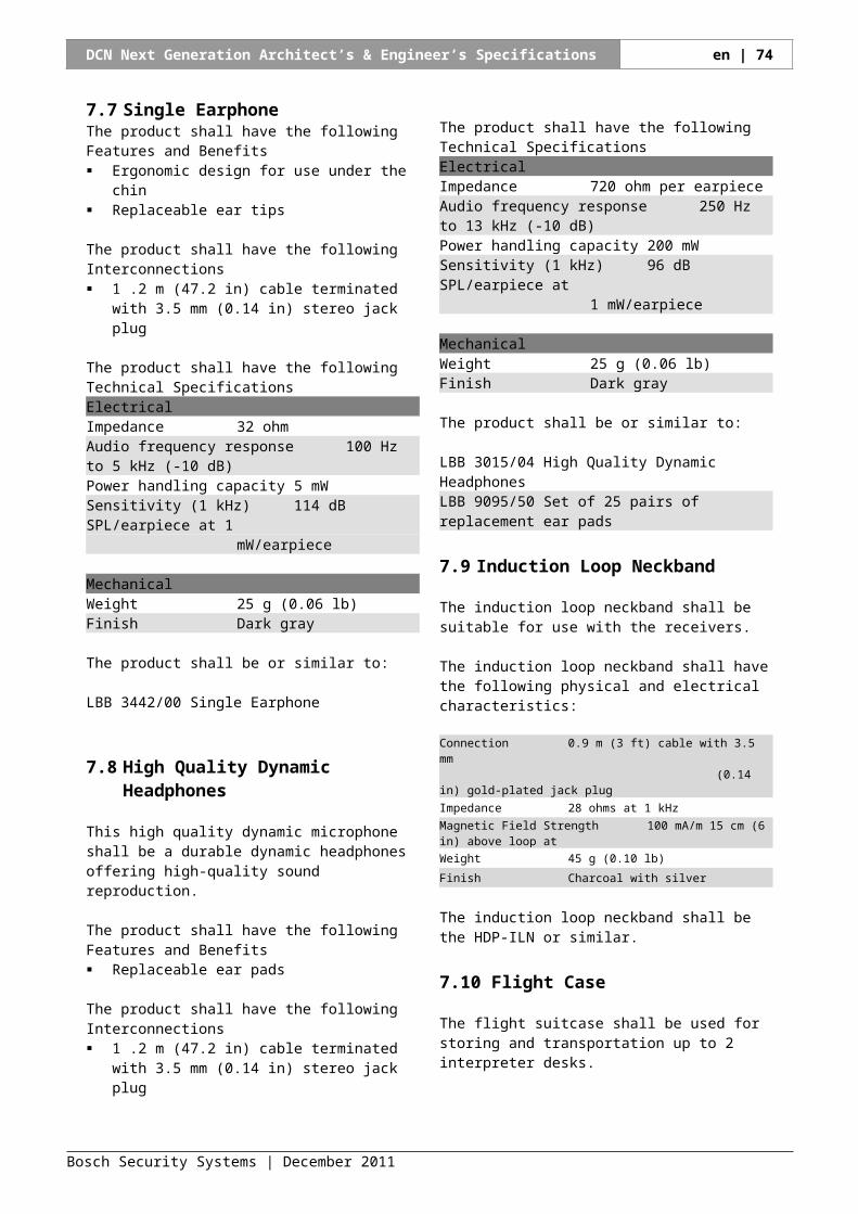
For more information please visit www.boschsecurity.com
© 2011 Bosch Security Systems B.V.Data subject to change without noticeDecember 2011