Embed Size (px)
Citation preview
Specifications
Additional information can be found online at www.heatilator.com
63-1/8" [1603]74" [1880]
15-5/8"[397]
48-1/2"[1232]
4"[102]
63"[1600]
8-9/16"[217]
Ø 8" [203]
1" [25]70" [1778]
17-1/8"[435]
18-5/8"[471]
47-3/4"[1213]
2-3/8"[60]
8-9/16"[217]
8-9/16"[217]
24-1/2"[622]
8-7/8"[225]
2-3/4"[70]
7-1/4"[184]
23-3/4"[603]
GAS ACCESS ELECTRICAL ACCESS
CENTERED ON APPLIANCE
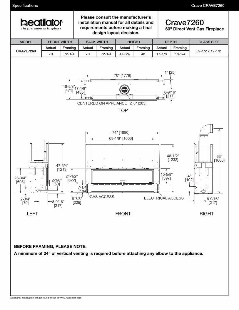
Please consult the manufacturer’s installation manual for all details and requirements before making a final
design layout decision.
Crave726060" Direct Vent Gas Fireplace
Crave CRAVE7260
MODEL FRONT WIDTH BACK WIDTH HEIGHT DEPTH GLASS SIZE
CRAVE7260Actual Framing Actual Framing Actual Framing Actual Framing
59-1/2 x 12-1/270 72-1/4 70 72-1/4 47-3/4 48 17-1/8 18-1/4
TOP
FRONTLEFT RIGHT
BEFORE FRAMING, PLEASE NOTE:
A minimum of 24" of vertical venting is required before attaching any elbow to the appliance.
Crave CRAVE7260
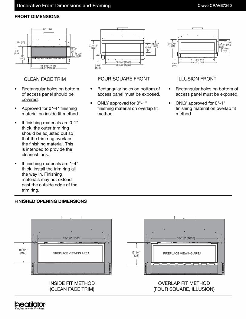
CLEAN FACE TRIM FOUR SQUARE FRONT ILLUSION FRONT
FRONT DIMENSIONS
FINISHED OPENING DIMENSIONS
Decorative Front Dimensions and Framing
25"[635]
24"[610]
13-1/8"[333]
16-3/4"[425]
64-5/16" [1634]
63" [1600]
61-3/16" [1554]
5/8" [16]27-5/16"
[692]
5-7/8"[149]
60-3/4" [1543]69-5/8" [1769]
12-5/8"[321]
21-3/8"[543]
27-5/16"[694]
5-7/8"[149]
61-1/8" [1553]69-1/2" [1765]
12-1/8"[308]
21-3/8"[543]
19-7/16"[494]
INSIDE FIT METHOD(CLEAN FACE TRIM)
FIREPLACE VIEWING AREA15-3/4"[400]
63-1/8" [1603]
OVERLAP FIT METHOD(FOUR SQUARE, ILLUSION)
FIREPLACE VIEWING AREA17-1/4"[438]
63-1/8" [1603]
• Rectangular holes on bottom of access panel should be covered.
• Approved for 0"-4" finishing material on inside fit method
• If finishing materials are 0-1” thick, the outer trim ring should be adjusted out so that the trim ring overlaps the finishing material. This is intended to provide the cleanest look.
• If finishing materials are 1-4” thick, install the trim ring all the way in. Finishing materials may not extend past the outside edge of the trim ring.
• Rectangular holes on bottom of access panel must be exposed.
• ONLY approved for 0"-1" finishing material on overlap fit method
• Rectangular holes on bottom of access panel must be exposed.
• ONLY approved for 0"-1" finishing material on overlap fit method
Specifications
GS/HTL/CRAVE7260_0618
PRODUCT LISTING CODES
US ANSI Z21.88-2014
CAN CSA 2.33-2014
UL307B
Additional information can be found online at www.heatilator.com
Product information provided is not complete and is subject to change without notice. Product installation must adhere strictly to instructions accompanying product to avoid risk of fire and potential injury.
Lakeville, MN Phone: (800) 927-6841Web: www.heatilator.com
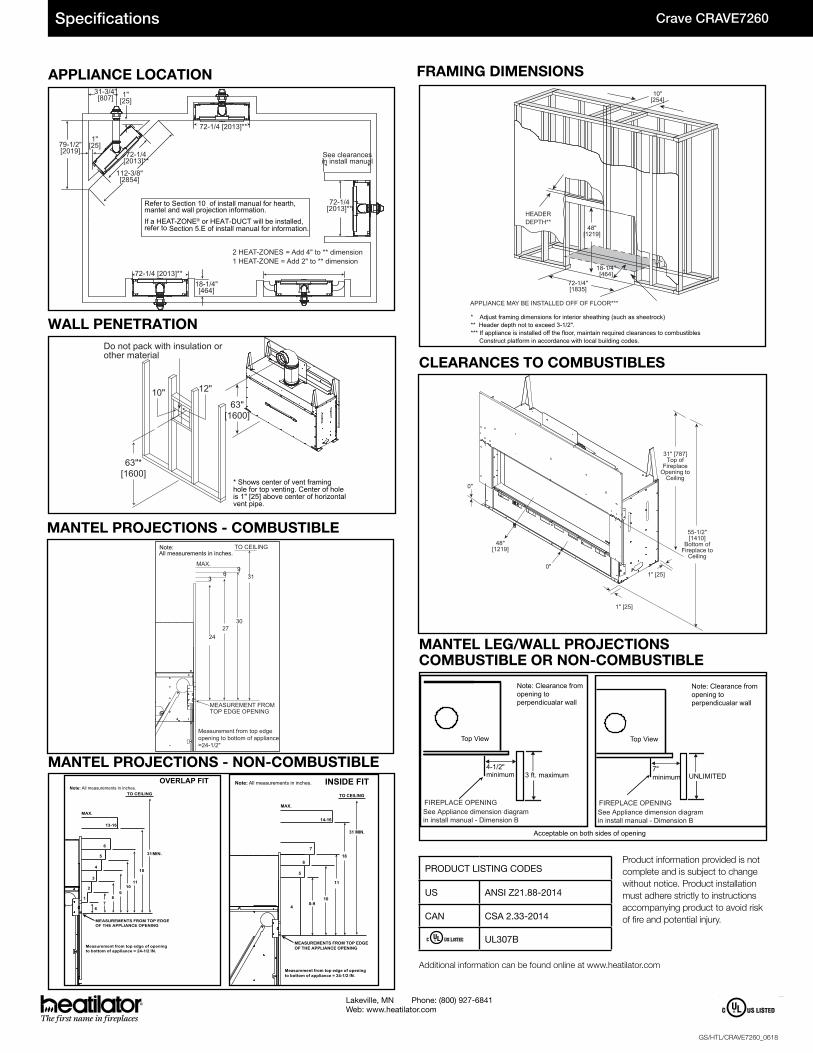
APPLIANCE LOCATION
WALL PENETRATION
MANTEL LEG/WALL PROJECTIONS COMBUSTIBLE OR NON-COMBUSTIBLE
112-3/8"[2854]
79-1/2"[2019] 72-1/4
[2013]**
72-1/4[2013]**
72-1/4 [2013]**
72-1/4 [2013]**18-1/4"[464]
31-3/4"[807] 1"
[25]
1"[25]
See clearancesin install manual
Refer to Section 10 of install manual for hearth, mantel and wall projection information. If a HEAT-ZONE® or HEAT-DUCT will be installed,refer to Section 5.E of install manual for information.
2 HEAT-ZONES = Add 4" to ** dimension1 HEAT-ZONE = Add 2" to ** dimension
FRAMING DIMENSIONS
CLEARANCES TO COMBUSTIBLES
48"[1219]
72-1/4"[1835]
10"[254]
HEADERDEPTH**
18-1/4"[464]
APPLIANCE MAY BE INSTALLED OFF OF FLOOR***
* Adjust framing dimensions for interior sheathing (such as sheetrock)** Header depth not to exceed 3-1/2".*** If appliance is installed off the floor, maintain required clearances to combustibles Construct platform in accordance with local building codes.
Note: All measurements in inches.
MEASUREMENTS FROM TOP EDGE OF THE APPLIANCE OPENING
4
5
6
13-16
3
2
1
67
89
1011
18
31
MAX.
MIN.
TO CEILING
Measurement from top edge of openingto bottom of appliance = 24-1/2 IN.
OVERLAP FIT
MEASUREMENTS FROM TOP EDGE OF THE APPLIANCE OPENING
4
5
6
14-16
0-910
18
31 MIN.
MAX.
TO CEILING
Measurement from top edge of openingto bottom of appliance = 24-1/2 IN.
7
11
INSIDE FITNote: All measurements in inches.
MEASUREMENT FROMTOP EDGE OPENING
2427
30
31
TO CEILING
96
3
Measurement from top edgeopening to bottom of appliance=24-1/2"
MAX.
Note: All measurements in inches.
MANTEL PROJECTIONS - NON-COMBUSTIBLE
MANTEL PROJECTIONS - COMBUSTIBLE
63"*[1600]
10" 12"
63"[1600]
Do not pack with insulation orother material
* Shows center of vent framinghole for top venting. Center of holeis 1" [25] above center of horizontalvent pipe.
3 ft. maximum4-1/2"minimum
FIREPLACE OPENINGSee Appliance dimension diagram in install manual - Dimension B
Note: Clearance from opening to perpendicualar wall
Top View
FIREPLACE OPENINGSee Appliance dimension diagram in install manual - Dimension B
Note: Clearance from opening to perpendicualar wall
Top View
7"minimum UNLIMITED
Acceptable on both sides of opening
48"[1219]
0"
1" [25]
1" [25]
31" [787]Top of
FireplaceOpening to
Ceiling0"
55-1/2"[1410]
Bottom ofFireplace to
Ceiling
Crave CRAVE7260


![Crave [music] Mag](https://img.pdfslide.us/doc/110x75/568c36fa1a28ab02359a0b71/crave-music-mag.jpg)