Embed Size (px)
DESCRIPTION
This review article is focusing in presenting a brief look on the archaeological photogrammetry and its uses. Also it gives a general presentation about the world heritage documentation and the visualization tools that are using to visualize the documented world heritage.
Citation preview
ARCHAEOLOGICAL PHOTOGRAMMETRY
AND
WORLD HERITAGE DOCUMENTATION
Review Article
By
Dr. Mostafa Abdel-Bary Ebrahim
Civil Engineering Department
Faculty of Engineering
Assiut University
February 2003
Archaeological Photogrammetry
and World Heritage Documentation
CONTENTS
Page
ABSTRACT ……………………………………………………………………………….. 1
CHAPTER 1 INTRODUCTION …………………………………..……………………. 2
CHAPTER 2 ARCHAEOLOGICAL PHOTOGRAMMETRY ………………………. 3
2.1 Introduction …………………………………………………………………………… 3
2.2 Definitions of Archaeology and Photogrammetry ………………………………….. 3
2.3 History of Photogrammetry and its Use in the Archaeology ………………….……. 4
2.4 Types of Photogrammetry Used in the Archaeological Applications ……………… 6
2.4.1 Introduction ……………………………………………………………………… 6
2.4.2 Arial Photogrammetry and Arial Archaeology ………………………….……. 7
2.4.3 Terrestrial Photogrammetry ……………………………………………………. 9
2.4.4 Close-Range Photogrammetry ………………………………………………….. 9
2.5 The Photogrammetric Techniques used in the Archaeological applications ………. 12
2.5.1 Introduction …………………………………………………………………….. 12
2.5.2 Analogue System ……………………………………………………………….. 12
2.5.3 Semi-analytical System ………………………………………………………… 12
2.5.4 Analytical System ………………………………………………………………. 13
2.5.5 Digital System …………………………………………………………………… 13
2.6 Fields of Application for Photogrammetry and Imaging in Archaeology………….. 14
2.6.1 Introduction ……………………………………………………………………. 14
2.6.2 Prospection and Landscape Archaeology…………………………………….. 14
2.6.3 Excavation………………………………………………………………………. 15
2.6.4 Recording of Caves, Mining and Cave Paintings……………………………. 17
2.6.5 Recording of Finds……………………………………………………………… 18
Page
CHAPTER 3 WORLD HERITAGE DOCUMENDATION …………………………… 20
3.1 Introduction …………………………………………………………………………… 20
3.2 The used methods for Documenting the World Heritage ………………………….. 23
3.2.1 Rectification ………..……………………………………………………………. 23
3.2.2 Draping ………………………………………………………………………….. 24
3.2.3 Digital Projector ………………………………………………………………… 25
3.3Visualization Tools for the Documented World Heritage….………………………... 28
3.3.1 Introduction …………………………………………………………………….. 28
3.3.2 Images ……………………………………………………………………………
28
3.3.3 DXF Files ………………………………………………………………………..
28
3.3.4 Animations ……………………………………………………………………… 29
3.3.5 VRML (Virtual Reality Modeling Language) ………………………………... 29
3.4 Examples of the Documented World Heritage ……………………………………… 31
CONCULSION ……………………………………………………………………………. 38
REFERENCES …………………………………………………………………………….. 39
ABSTRACT
No doubt that we are in need to find out a way to document our heritage in a
reasonable way which keep it in save with all its fine details. There are lots of
researches, which have been done to document the world heritage.
In past, the only way to document the world heritage was writing the target
description in files and keep it in a save place. This method was dangerous
something as it’s very easy to loose the document by fire or bad saving
condition.
As the photogrammetric science is existed, it has been used in the field of
archaeology for several aims. The application of the photogrammetry in the
archaeological field is called Archaeological Photogrammetry.
Fields of application for photogrammetry in archaeology can be Prospection
and Landscape Archaeology, Excavation, Recording of Caves, Mining and Cave
Paintings, and Recording of Finds.
All the Photogrammetric types are used in the Archaeological field, Arial,
Terrestrial, and close-range. Also, all the Photogrammetric techniques are used
in that field without any limitations.
Nowadays with the development of the computer science and its uses, the
documentation of the world heritage became easier and accurate. It can be done
by using what is called “Digital Photogrammetry”. This depends mainly in the
imagery and computer models. Lots of methods, techniques, and softwares are
used to document the world heritage. Some of these methods end with a special
techniques and software, but some others using the already exist commercial
softwares.
In this review article, all the areas that concerning the Archaeological
Photogrammetry and world heritage documentation will be presented.
CHAPTER 1
INTRODUCTION
Documentation and conservation of cultural heritage are being increasingly seen as tasks of
national, ultimately international priority. Due to the digital techniques, photogrammetry now
appears as more efficient and inexpensive; today ’s user-oriented software is easier to handle
by non-experts, thus widening the potential spectrum of application in architectural and
archaeological recording (Petros PATIAS,J uergen PEIPE, 2000) .
Different types and techniques of photogrammetry are used in the field of archaeology for
excavation and documentation the world heritage.
This review article is focusing in presenting a brief look on the archaeological
photogrammetry and its uses. Also it gives a general presentation about the world heritage
documentation and the visualization tools that are using to visualize the documented world
heritage.
Chapter 2 is about the Archaeological Photogrammetry, which contains definitions of
Archaeology And Photogrammetry, history of Photogrammetry and its use in the
Archaeology, types of Photogrammetry used in the Archaeological Applications (Arial,
terrestrial, and close-range photogrammetry), and the photogrammetric techniques used in the
Archaeological Applications (Analogue, Semi-analytical, analytical and digital).
Chapter 3 talkes about the World Heritage Documentation. In this chapter, the used methods
in documenting the world heritage are presented. These methods are: the rectification,
draping, the digital projector. Also, a full description of the visualization tools for the
documented world heritage is presented. The presented visualization tools are: Images, DXF
files, animations, and VRML (virtual reality modeling language). Some of the archaeological
photogrammetry applications and world heritage documentation examples are presented.
At last, a conclusion about the subject is written to view the main elements and features of the
subjects. A list of references is provided for further review.
CHAPTER 2
ARCHAEOLOGICAL PHOTOGRAMMETRY
2.1 Introduction
Archaeological Photogrammetry is defined as the use of the photogrammetric types and
techniques in the field of archaeology. It is considered as one of the most important
applications of Photogrammetry. In the next sections, photogrammetry and archaeology will
be defined, a brief history of the photogrammetry and its use in archaeology will be presented,
and the photogrammetric types and techniques used in the archaeological field will be
presented too.
2.2 Definitions of the Archaeology and Photogrammetry
Archaeology
It is defined as the branch of anthropology that studies prehistoric people and their
cultures [Site 1]. There have been also multiple definitions of what archaeology is through
the history of the discipline. Several of these definitions define archaeology as a discipline
largely concerned with artifacts, in particular pottery, potshards, and arrow points, or with the
excavation of large scale sites such as palaces and ancient pyramids. Alternate definitions
define archaeology as the study of antiquity, emphasizing the archaic nature of archaeological
remains. By and large however, such definitions are incomplete. Reflecting the historical and
theoretical biases of the early stages of archaeology as a discipline. Archaeology has become
a science that is no longer the archaic study of antiquity and ancient archaic artifacts; rather it
has become a dynamic study focusing upon cultural relevance, cultural context, and the vast
overall scheme of a given archaeological picture of a given peoples. How archaeology
accomplishes this is by examining in whole, not the gross obvious evidence such as large
pots, jewel encrusted shrines, and large temples, but rather, archaeology has come to focus
upon smaller scale and less spectacular remains as well. By focusing upon less obvious
remains, the science itself has shifted from a study dominated by treasure hunting and half
composed (if not wrong) theories of culture, to a science which attempts to understand
holistically the context and culture of a given site and the gross overall completeness of a
culture [Site 2].
Photogrammetry
It can be defined as the art, science and technology of obtaining reliable information about
physical objects and the environment through processes of recording, measuring and
interpreting photographic images and patterns of recorded radiant electromagnetic energy
(Slama, 1980). It’s also defined as the technique of measuring objects (2D or 3D) from photo-
grammes. It’s said commonly photographs, but it may be also imagery stored electronically
on tape or disk taken by video or CCD cameras or radiation sensors such as scanners [Site 3].
2.3 History of Photogrammetry and its Use in the Archaeology
Since the beginning of the photogrammetric science, it has been applied in the field of
archaeology. A brief history of photogrammetry and its uses in the archaeology field can be
presented as mentioned in the Technical University of Vienna web site [Site 3 & 4] as
follows:
Brief History of photogrammetry
1851: Only a decade after the invention of the „Daguerrotypie“ by Daguerre and
Niepce, the _tereo officer Aime Laussedat develops the first
photogrammetrical devices and methods. He is seen as the initiator of
photogrammetry.
1858: The German architect A. Meydenbauer develops photogrammetrical
techniques for the documentation of buildings and installs the first
photogrammetric institute in 1885 (Royal Prussian Photogrammetric
Institute).
1866: The Viennese physicist Ernst Mach publishes the idea to use the stereoscope
to estimate volumetric measures.
1885: The ancient ruins of Persepolis were the first archaeological object recorded
photogrammetrically.
1889: The first German manual of photogrammetry was published by C. Koppe.
1896: Eduard Gaston and Daniel Deville present the first stereoscopical instrument
for vectorized mapping.
1897/98: Theodor Scheimpflug invents the double projection.
1901: Pulfrich creates the first „Stereocomparator“ and revolutionates the mapping
from stereopairs.
1903: Theodor Scheimpflug invents the „Perspektograph“, an instrument for optical
rectification.
1910: The ISP (International Society for Photogrammetry), now ISPRS, was
founded by E. Dolezal in Austria.
1911: The Austrian Th. Scheimpflug finds a way to create rectified photographs. He
is considered as the initiator of aerial photogrammetry, since he was the first
succeeding to apply the photogrammetrical principles to aerial photographs.
1913: The first congress of the ISP was held in Vienna.
Until 1945: development and improvment of measuring (=„metric“) cameras and
analogue plotters.
1964: First architectural tests with the new stereometric camera-system, which had
been invented by Carl Zeiss, Oberkochen and Hans Foramitti, Vienna.
1964: Charte de Venise.
1968: First international Symposium for photogrammetrical applications to
historical monuments was held in Paris – Saint Mandé.
1970: Constitution of CIPA (Comité International de la Photogrammétrie
Architecturale) as one of the international specialized committees of
ICOMOS (International Council on Monuments and Sites) in cooperation
with ISPRS. The two main activists were Maurice Carbonnell, France, and
Hans Foramitti, Austria.
1970ies: The analytical plotters, which were first used by U. Helava in 1957,
revolutionate photogrammetry. They allow to apply more complex methods:
aerotriangulation, bundle-adjustment, the use of amateur cameras etc.
1980ies: Due to improvements in computer hardware and software, digital
photogrammetry is gaining more and more importance.
Brief History of Aerial Archaeology
Aerial archaeology is an old prospection technique. The first attempts, to use the distant view
for archaeological purposes were already made during the last century. There are only a few
aerial photographs from the early times. Among these are recordings of Stonehendge (what
else would you expect?) from 1906 and the Forum Romanum (1906 to 1908). They were
made out of balloons.
More systematic recordings were done during World War I, when German military aviators -
instructed by Theodor Wiegand - photographed ruined towns and cities in Sinai. In these
years, airplanes were used the first time with aerial archaeology.
In the 1920s, aerial archaeology got a theoretical background. Two persons are to be
mentioned here: O.G.S. Crawford in England and P.A. Poidebard in Syria. Crawford is said to
be the inventor of scientific aerial archaeology. In March 1923, he gave a lecture to the Royal
Geographical Society, where he showed aerial views of the "Celtic fields", old soil marked
field boundaries at Windmill Hill, which he had photographed during 1922. In 1924, he made
the first archaeological flying season over Wessex, producing several black and white plates
of a very high quality.
After World War II, also the other western European countries started with systematic aerial
archaeological research work. Dr. J.K. St.Joseph began flying over England. He was head of
the Cambridge University Collection of Aerial Photographs (CUCAP) until 1980.
In Austria, flying was prohibited until 1928, due to the peace terms after World War I. In the
1930s, aerial archaeological photographs were made at the "Braunsberg" and in the nearby
area of Carnuntum, Lower Austria. In 1931, a sequence of vertical photographs from the
Braunsberg was analyzed by E. Nischer-Falkenhof to support his excavations.
In Austria, systematic aerial archaeological research had its beginnings in 1961. In this year, a
section for aerial photography was founded within the Austrian Society for Prehistory by G.
Spitzer and an archive for aerial photographs was installed. Contacts were made with the
Austrian air force. These were intensivated by the then student H. Friesinger, who became
leader of the aerial archaeological section a few years later.
Almost two decades later, in 1979, it became part of the Institute for Prehistory in Vienna and
necessary instruments for analysis of aerial photographs were purchased. Over the years,
better standards and a broader range of applications were requested, so that the archive got
modern photogrammetrical hard- and software. By now, the aerial archive is the only
institution in Austria, which is seriously dealing with aerial archaeology .
2.4 Types of the Photogrammetry used in the Archaeological applications
2.4.1 Introduction
The types of Photogrammetry are depending mainly on the way that the photos have been
taken. The photos can be taken from Airplane, from the ground, or inside doors. It can be
taken by using metric cameras or non-metric cameras. It can be taken by using analog
cameras or digital cameras.
The basic fields of application in the science of Photogrammetry are defined as aerial
Photogrammetry and terrestrial Photogrammetry which include an important branch which
has a numerous of applications, it is called Close range Photogrammetry.
2.4.2 Arial Photogrammetry and Arial Archaeology
Arial Photogrammetry
Aerial Photogrammetry is the branch of Photogrammetry, which deals with the aerial
photographs, which commonly classified as either vertical or oblique photographs. Vertical
photos are taken with the camera axis directed as nearly vertically as possible. For many
practical applications the simple procedures suitable for analyzing truly vertical photos may
also be used for tilted photos without serious consequences. Precise Photogrammetry
instruments and procedures have been developed, whoever, that make it possible rigorously
accounts for tilt with no loss of accuracy at all. Oblique aerial photographs are exposed with
camera axis intentionally tilted away from vertical. A high oblique photograph includes the
horizon while a low oblique does not. In case of terrestrial Photogrammetry, the vertical
photos are called normal photos, and the oblique photos are called convergent photos.
Introduction to Aerial Archaeology
It is common opinion that an aerial archaeologist is sitting in an airplane, trying to discover
archaeological sites and to take a few nice photographs of them.
This is (somehow) true. But aerial archaeology is more than just taking photographs, although
this was and sometimes is still considered to be its main subject. In fact, it goes far beyond the
mere acquisition of data, and you even don’t need photographs to perform aerial archaeology:
you can use also satellite images, thermal images or airborne radar images. To perform aerial
archaeology means above all, to make archaeological use of this kind of remotely sensed
information.
The terms "aerial" or "remotely sensed information" already indicate, how aerial archaeology
works: it uses the distant view. Archaeological sites show up on the ground surface,
depending on their state of preservation, by light-shadow-contrasts (shadow marks), tonal
differences in the soil (soil marks) or differences in height and color of the cultivated cereal
(crop marks). In that way, settlements, graveyards, fortifications etc. produce specific
structures that can be identified easier from a high viewpoint.
In principle, you could see an archaeological feature also while standing on it, but like a cat
on the carpet, you would not be able to realize any pattern, that could give you a bit more
information about WHAT this site could be like. If you choose a more distant viewpoint (even
if it’s only a ladder or a building), the structures become clearer to you and the pattern
becomes understandable.
Aerial Archaeology and Prospection
Today, it is not only the upstanding remains of our cultural heritage that is increasingly
threatened with destruction. There is an even bigger amount of archaeological sites still
hidden in the subsoil. Many of them are in a very bad condition due to intensive agriculture
and the exploitation of our resources. Others are already vanished. If these were prior
unknown - which comes true of a good deal - they are leaving irretrievable holes in the
archaeological landscape. To prevent this, the archaeologist tries to detect, document and map
archaeological sites, aiming to protect them or at least to extract from them as much
information as possible, before they are destroyed. This is called "archaeological
prospection".
In the public opinion, archaeology is mostly connected with excavation. As a matter of fact,
excavation is performed rather as a final step; it is somehow seen as the last resort to protect
our cultural heritage by "destroying" a site scientifically, before it is deserted by bulldozers.
Excavation of sites solely because of scientific interest is very rare nowadays. Today, the
archaeologist is much more concerned with the non-destructive protection of sites, which is -
by the way - cheaper. Therefore, a broad range of prospecting techniques have been
developed.
Each of these prospection techniques has different aims, methods, advantages and drawbacks.
None of them can be seen as the "non plus ultra".
Aerial archaeology is one of the oldest prospection methods. It is very productive and (in
relation to other methods) cheap, because you can cover quite a large area within a small
number of flighing-hours and you can use any existing aerial photograph for your
interpretation. A good example to illustrate this is the vertical aerial photograph of the area
around Hornsburg in Lower Austria.
On the other hand, this picture shows also some of the limitations of aerial archaeology: there
are plenty of factors (as soil type, climate, flying hour, vegetation etc...), which affect the
visibility of sites. In many cases, as for example at the two middle Neolithic ditch systems in
our picture, only the mayor structures (in our case the ditches) show up on the surface. The
settlements around them are in this photograph invisible, although they probably could be
seen under different circumstances. Therefore, it is important, to combine different
prospection techniques. Doing this, you can use the advantages of each, thus enabling
optimized results. In Vienna, we have already experience in the combination of geophysical
prospection with aerial archaeology [Site 12].
2.4.3 Terrestrial Photogrammetry
Terrestrial Photogrammetry is an important branch of the science of Photogrammetry. It deals
with photographs taken with a camera located on the surface of the earth. Unlike aerial
photography, with terrestrial photography the cameras are usually accessible, so that direct
measurements can be made to obtain exposure station position. Camera angular orientation
can also usually be measured or set to fixed values, so that all elements of exterior orientation
of a terrestrial photo may be commonly known and do not need to be calculated (Wolf, 1974)
(External orientation is the exposure station space co-ordinates and the inclined angles of the
photo plane with an arbitrary space axis). These known exterior orientation parameters are a
source of control for terrestrial photos, replacing in whole or in part the necessity for locating
control points in the object space.
Terrestrial photography may be static (photos of stationary objects) or dynamic (photos of
moving objects). For static photography, slow, fine-grained, high-resolution film may be used
and exposures made by simply removing a lens cap (shutter) for a short time. Stereopairs can
be obtained by using a single camera and making exposures at both ends of a base line. In
taking dynamic terrestrial photos, fast films and rapid shutter speeds are necessary. If
stereopairs of dynamic occurrences are required, two cameras located at the end of a base line
must make simultaneous exposures (Wolf, 1974). Nowadays the term terrestrial
Photogrammetry doesn’t use any more, because of the fast improvement in close range
techniques and its wide applications.
2.4.4 Close-Range Photogrammetry
Close range Photogrammetry is a branch of terrestrial Photogrammetry in which the
photographs are taken from a limited object distance. The value of the object distance is not
fixed at a certain value but it differs from one case to another. Wolf, 1974 defined close range
Photogrammetry where the object distance is up to about 100 meter, but Torlegard, 1976
mentioned that the range is limited by a certain distance, for instance 1000 ft. In 1981
Torlegard added that the maximum distance for close range Photogrammetry is 300 meter and
the minimum is a fraction of millimeter. Karara, 1989, ensured the same range of object
distances of 300 meter as a maximum limit, while the minimum distance is essentially zero
(say a fraction of a millimeter) to encompass macro-and microscopic photographs. Hottier,
1976, suggested the range of close range Photogrammetry as from 0 to 200 meters.
Close range Photogrammetry is similar to classical topographic Photogrammetry in many
respects, in particular when the solution is carried out analytically. An important and
fundamental difference between the two types is in the definition and realization of datum. In
topographic Photogrammetry the datum is realized through geodetic control points, which are
kept fixed or are heavily weighted in the solution. In close range Photogrammetry, control is
provided usually by precise measurements, which are of a distinctly differential natural (Papo,
1982). In close range Photogrammetry, not only central projection (bundles and pencils of
rays) is used for mathematical models of image formation, but also parallel projection,
scanner generated images (direction or distance) and others. Not only are camera and film
used as sensor system, but also x-rays, scanning and transmission electron microscopes;
photodiode arrays with analogue or digital output are also suitable for Photogrammetric
measurements. In close range Photogrammetry the derived quantities, which result from the
measurements, may, for example, be area, volume, angle and lack of flatness. Time is
sometimes the fourth dimension in close range photogrammetry, yielding speed, acceleration
and deformation. (Torlegard, 1981)
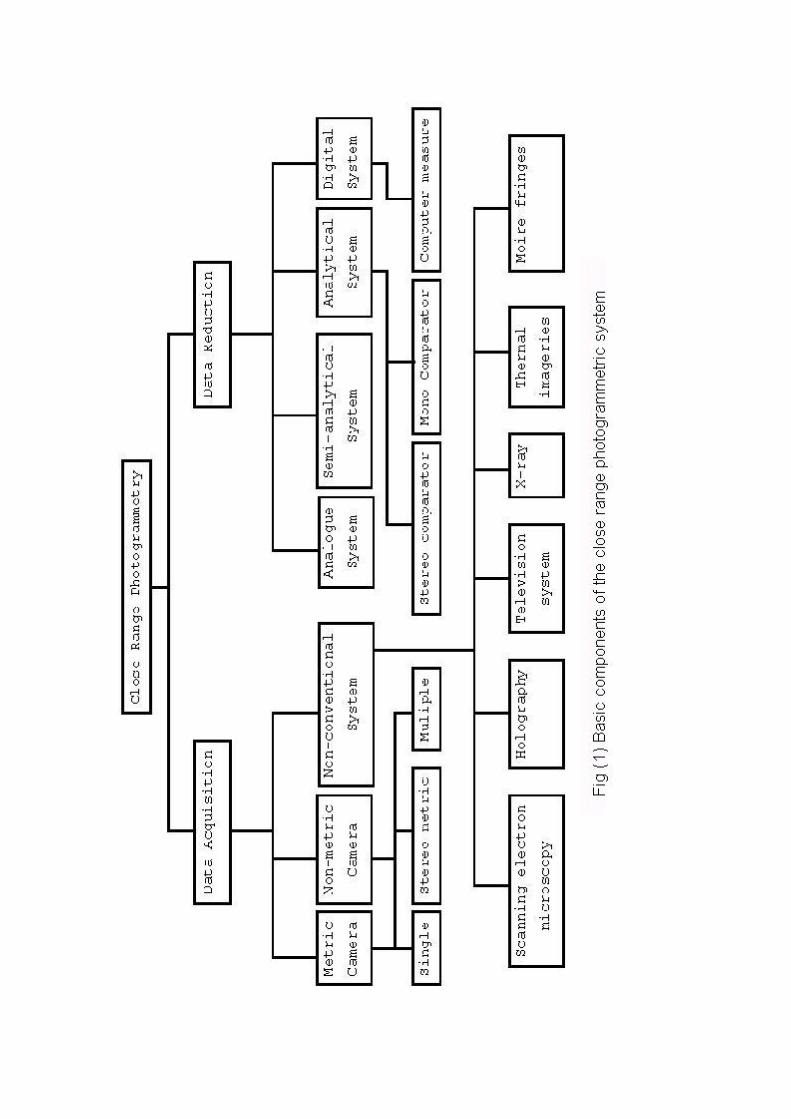
Back to the history of close range photogrammetry, since its early days, the first and for most
application of photogrammetry was in the field of topographic mapping. In recent years
photogrammetry has been applied in other fields such as medical science, architecture,
archaeology, industry, civil and structural engineering. Close range photogrammetry has been
used also in a lot of differences fields especially after the wide using of the digital images in
photogrammetry. Figure (1) shows the close range system scheme.
2.5 The Photogrammetric Techniques Used in the Archaeological Applications
2.5.1 Introduction
Photogrammetry has different techniques’ systems, which are different in the used
instruments and in the used data reduction systems. These techniques are analogue system,
semi-analytical system, analytical system and digital system. Some of these techniques are not
used nowadays.
2.5.2 Analogue System
Analog photogrammetric systems are represented by conventional photogrammetric plotters
of optical and mechanical design, which are basically special-purpose analog computers.
As such, they inherently operate on-line by providing a geometrically accurate optical
feedback from the model space to operator-observed image spaces and by preserving the
continuity of processing.
Special plotting instruments, introduced for use in conjunction with stereometric and single
metric cameras, have been available. Such plotters were, in general, designed for the normal
case of photogrammetry, and thus the term “normal-case of stereoplotters” is sometimes used
to refer to this group of instruments.
The analog photogrammetry is suitable for data reduction from metric photographs but is not
recommended for precision evaluation of non-metric photography in view if the rather large
and sometimes irregular lens and film distortions associated with non-metric photography.
The analog photogrammetry cycle was from around 1900 to about 1960 which initiated by
two inventions: stereoscopy and the introduction of suitable sensor platforms.(Karara, 1989)
2.5.3 Semi-analytical System
Semi-analytical photogrammetry usually utilizes an analog stereoplotter for basic measuring
tasks together with numerical (analytical) evaluation. In its most common form the
stereoplotter is used to form a stereomodel of the object by performing optical/mechanical
relative orientation. Subsequent absolute orientation (scaling and leveling) is done
analytically. At this stage, corrections for model deformations can be applied. The use of a
stereoplotter rather than a comparator and the added flexibility resulting from the analytical
phase can make this type of evaluation quite attractive for users.
This approach has great potential because the general trend towards analytical plotters and
digital procedures in the mapping industry may free older high precision analog instruments
for bargain prices, which together with small computers provide an ideal, highly accurate and
economical means to tackle close range photogrammetric projects. (Karara,1989)
2.5.4 Analytical System
Analytical photogrammetry deals with the solution problems by mathematical computations,
by using measurement data obtained from the photograph (image) as input. Suitable
mathematical models are used to represent relations between points in the object, their
corresponding images and errors in the system.
Analytical photogrammetry is, however, rapidly becoming more and more complex. Increased
complexity does not necessarily mean increasing worth. By being more complex, it may
become less used because of the concern of the potential user. In this respect, it would be
pertinent to emphasize that such situations call for wisest possible treatments of
photogrammetric resources and all involved technologies with sensible innovations at all
stages (Sanjib, 1988).
The analytical photogrammetry cycle is from around 1899 onward. The evolution of the
analytical photogrammetry was from around 1960 onward which initiated by the invention of
the electronic computer (Karara, 1989).
2.5.5 Digital System
Digital photogrammetry system is essentially a sequential process in which either the hard-
copy photographs are first digitized or the images are directly acquired with digital cameras;
then the digital data are processed in computers some times with human interference and
some times without. As such, digital photogrammetry involves the practice of using pixels
and image processing techniques to arrive at geometric information.
The most distinguishing characteristic of a digital image, as compared with a continuous-tone
hard-copy image, is that it is formed by a set of discrete, very small, but finite, picture
element, or pixels. Each pixel is essentially a square area (e.g. 25 X 25 micrometers) of
uniform photo density. Therefore, image measurements are often expressed in terms of pixels
and fractions thereof. The CCD camera produces such a digital image, which is processed on-
line.
The digital photogrammetry cycle is from around 1980 onward. The transition from analytical
to digital photogrammetry has been a quiet and gradual one and was initiated by the advent of
satellites, starting with Sputnik in the U.S.S.R. in 1975. The development of digital
photogrammetry has been going parallel with the development of remote sensing.
Photogrammetry has been used quite a lot lately for the mapping of archaeological sites and
for the registration and documentation of excavation findings. Photogrammetric software and
Digital Photogrammetric Stations (DPS) have not been easy to use tools for any archaeologist
since the knowledge and experience bakground needed for this purpose is very demanding. A
DPS user should be familiar on the use of computers and should have specialized knowledge
on CAD programs, besides the obvious need of photogrammetric knowledge (Vassilios
Tsioukas, Petros Patias, 2002).
2.6 Fields of Application for Photogrammetry and Imaging in Archaeology
2.6.1 Introduction
Photogrammetry and imaging have a lot of applications in the field of archaeology, which
illustrate the importance of using such sciences in the archaeological field. Here is a (certainly
not complete) list of fields of application for photogrammetry and imaging in archaeology
[Site 7].
2.6.2 Prospection and Landscape Archaeology
- Analysis of vertical and oblique photographs: in most cases, archaeologists want to
have exact and detailed mappings of the archaeological information that can be seen
in vertical and oblique photographs.
- Visualization of a site’s topography: contour lines, digital terrain models or profiles of
the surface can be depicted together with archaeological information from photos or
from results of excavations.
- Digital orthophotos: they are a very important aid for archaeology. Structures
showing up on the surface are depicted together with all of the image-information.
Image enhancement, pattern recognition and subsequently expert systems are
applicable with orthophotos.
- Combination of the data mentioned above with results from other (especially
geophysical) prospection techniques within a GIS system.
- Landscape archaeologists are in need of data made by satellites; they are mostly used
for “Predictive Modeling”, that is to assess the likelihood of finding significant
archaeological materials in given areas.
2.6.3 Excavation
Different kinds of excavations require different solutions:
- Rescue excavations: very fast solutions, accuracy is second place
- Stratigraphic excavations: 3-D models of strata
- Excavations of graveyards and burial sites: sometimes several thousands of skeletons;
standardized recording procedure
- Excavations of settlements without stone walls: recording procedures can change
depending on features; any used system must be adaptable
- Excavations of settlements with stone walls: to go on with excavation, walls and
pavements must be removed - they have to be documented first; (especially
excavations in towns can be very complicated); documentation of wall-paintings;
- Excavations in moist areas: organic materials (tools, wooden pavements, wooden
walls etc...) have to be recorded instantly
- Excavations in remote areas without infra structure (desert, jungle, mountain...)
- Excavations underwater: there are special problems, which require sophisticated
resolutions;
- Excavation of hunter-gatherer sites that require different solutions.
Examples:
1- Gars/Thunau, Early Medieval Church
The slavic settlement of Gars/Thunau is being excavated since 1965. In 1987, the foundations
of an early medieval church were found. These were documented during the excavation using
a stereometric camera (SMK 40 and 120). The glass plates were analyzed using an analytical
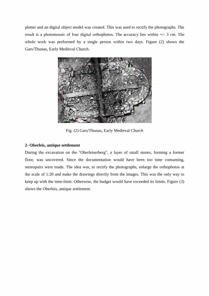
plotter and an digital object model was created. This was used to rectify the photographs. The
result is a photomosaic of four digital orthophotos. The accuracy lies within +/- 3 cm. The
whole work was performed by a single person within two days. Figure (2) shows the
Gars/Thunau, Early Medieval Church.
Fig. (2) Gars/Thunau, Early Medieval Church
2- Oberleis, antique settlement
During the excavation on the "Oberleiserberg", a layer of small stones, forming a former
floor, was uncovered. Since the documentation would have been too time consuming,
stereopairs were made. The idea was, to rectify the photographs, enlarge the orthophotos at
the scale of 1:20 and make the drawings directly from the images. This was the only way to
keep up with the time-limit. Otherwise, the budget would have exceeded its limits. Figure (3)
shows the Oberleis, antique settlement.
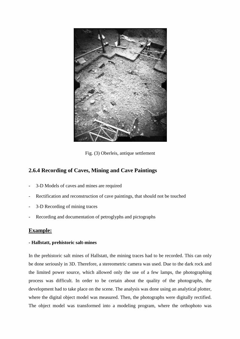
Fig. (3) Oberleis, antique settlement
2.6.4 Recording of Caves, Mining and Cave Paintings
- 3-D Models of caves and mines are required
- Rectification and reconstruction of cave paintings, that should not be touched
- 3-D Recording of mining traces
- Recording and documentation of petroglyphs and pictographs
Example:
- Hallstatt, prehistoric salt-mines
In the prehistoric salt mines of Hallstatt, the mining traces had to be recorded. This can only
be done seriously in 3D. Therefore, a stereometric camera was used. Due to the dark rock and
the limited power source, which allowed only the use of a few lamps, the photographing
process was difficult. In order to be certain about the quality of the photographs, the
development had to take place on the scene. The analysis was done using an analytical plotter,
where the digital object model was measured. Then, the photographs were digitally rectified.
The object model was transformed into a modeling program, where the orthophoto was
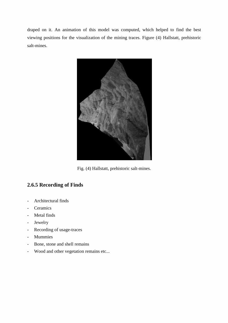
draped on it. An animation of this model was computed, which helped to find the best
viewing positions for the visualization of the mining traces. Figure (4) Hallstatt, prehistoric
salt-mines.
Fig. (4) Hallstatt, prehistoric salt-mines.
2.6.5 Recording of Finds
- Architectural finds
- Ceramics
- Metal finds
- Jewelry
- Recording of usage-traces
- Mummies
- Bone, stone and shell remains
- Wood and other vegetation remains etc...
Example:
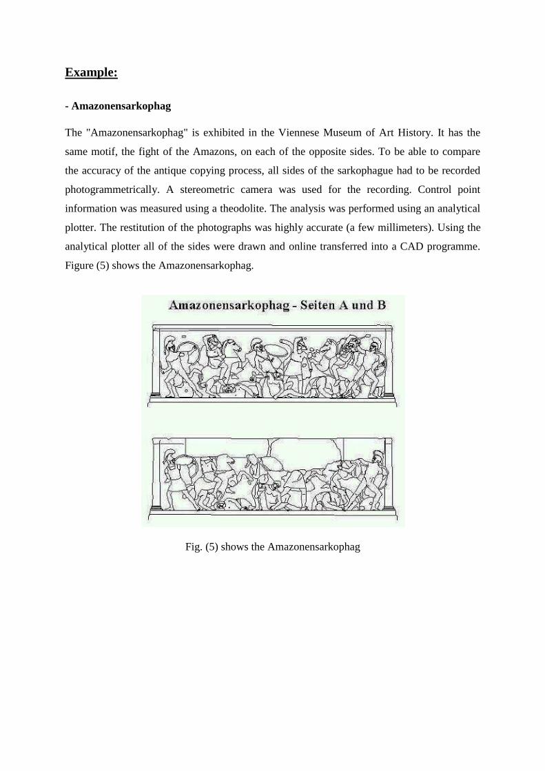
- Amazonensarkophag
The "Amazonensarkophag" is exhibited in the Viennese Museum of Art History. It has the
same motif, the fight of the Amazons, on each of the opposite sides. To be able to compare
the accuracy of the antique copying process, all sides of the sarkophague had to be recorded
photogrammetrically. A stereometric camera was used for the recording. Control point
information was measured using a theodolite. The analysis was performed using an analytical
plotter. The restitution of the photographs was highly accurate (a few millimeters). Using the
analytical plotter all of the sides were drawn and online transferred into a CAD programme.
Figure (5) shows the Amazonensarkophag.
Fig. (5) shows the Amazonensarkophag
CHAPTER 3
WORLD HERITAGE DOCUMENDATION
3.1 Introduction
A lot of precious old cultural heritages remain all over the world. These heritages are of great
value for human being in both history and art. Some of these old cultural heritages face a
crisis that these are going to be collapsed naturally and/or artificially. These become gradually
worse by weathering, plants, animals and human activities. Appropriate treatments for these
are urgently requested at present. Although various technologies have been attempted to
preserve or restore old cultural heritages, it is the most important to record the current status
of the object precisely and preservation or restoration histories of them accurately. These
records are necessary to monitor status of both damaged parts and restored parts of the target.
A restoration researcher can make an appropriate preservation or restoration plan based on
these records. However, precise and accurate records of an old cultural heritage are not
necessarily available. Precise records of the current status of the object have been available by
photogrammetric technique (Kenji Hongo, et al, 2000).
The graphic representation of historical monuments is traditionally performed with the
assistance of tape measure. With this purpose, all the necessary elements for its representation
are measured is based on direct measurements on the monument. These measurements are
time consuming dependent on the conservation state of the monument. They can even damage
the monument. After the Second World War, the conservation of monuments was motivated,
leading, in 1964, to elaboration of the International Charter about conservation and restoration
of monuments, known as Charter of Venice. Since then, several countries began to establish
programs for maintenance of their historical monuments. The International Council of
Monuments and Sites – ICOMOS recommended that each country should constitute a
photogrammetric record of its monuments and sites, since photogrammetry is considered the
main and more advanced method for surveying (Simone da SILVA * , Quintino
DALMOLIN, 2000).
When we talk about the word World Heritage Documentation, it comes to our mind three of
the most famous international organizations, which are concerning about it. These
organizations are: UNESCO, CIPA, and IOCOMS. These international organizations are fully
or partially concerned of the world heritage preservation, conservation and documentation.
The UNESCO
It is the United Nations Educational, Scientific and Cultural Organization. Its constitution was
adopted by the London Conference in November 1945, and entered into effect on the 4th of
November 1946 when 20 states had deposited instruments of acceptance.
It currently has 188 Member States (as of 19 October 1999).
The main objective of UNESCO is to contribute to peace and security in the world by
promoting collaboration among nations through education, science, culture and
communication in order to further universal respect for justice, for the rule of law and for the
human rights and fundamental freedoms which are affirmed for the peoples of the world,
without distinction of race, sex, language or religion, by the Charter of the United Nations.
[Site 8]
The CIPA
It is the international committee for architectural photogrammetry. In 1970, the CIPA has
been set up as a joint committee between the two non-governmental organizations ICOMOS,
the international council on monuments and sites, and ISPRS, the international society of
photogrammetry and remote sensing, with the “specific task to promote the development of
photogrammetry for the surveying of monuments and sites and for the international
cooperation in this area; to establish links between architects, archaeologists and
conservations on the one side and photogrammetry technologists and technicians on the other;
to arrange for the ex-change and circulation of ideas, knowledge, experience and results of
researches; to develop contacts with the appropriate institution s and with firms specializing in
the execution of photogrammetric surveys or the building of photogrammetric equipment.”
(CIPA Statutes 1979). (Peter Waldhaeusl, 1997)
CIPA Working Groups / Task Groups [Site 9]
WG 1 - Recording, Documentation and Information Management
WG 2 - Cultural Heritage Information Systems
WG 3 - Simple Methods for Architectural Photogrammetry
WG 4 - Digital Image Processing
WG 5 - Archaeology and Photogrammetry
WG 6 - Surveying Methods for Heritage Recorders
WG 7 – Photography
WG 8 - Cultural Landscapes
TG 1 - Non-professional Heritage Recorders
TG 2 - Single Images in Conservation
The ICOMOS
It is an international, non-governmental organization dedicated to the conservation of the
world's historic monuments and sites. The organization was founded in 1965, as a result of the
international adoption of the Charter for the Conservation and Restoration of Monuments and
Sites in Venice the year before. Today the organization has National Committees in over 107
countries.
ICOMOS is UNESCO's principal advisor in matters concerning the conservation and
protection of monuments and sites. With IUCN-The World Conservation Union, ICOMOS
has an international role under the World Heritage Convention to advise the World Heritage
Committee and UNESCO on the nomination of new sites to the World Heritage List.
Through its 21 International Scientific Committees of experts from around the world, and
through its triennial General Assembly, ICOMOS seeks to establish international standards
for the preservation, restoration, and management of the cultural environment. Many of these
standards have been promulgated as Charters by the organization as a result of adoption by
the ICOMOS General Assembly.
ICOMOS activities are governed by a set of Statutes, which were adopted by the Fifth
General Assembly in Moscow on May 22nd, 1978. [Site 10]
ICOMOS Aims and Activates:
- To bring together conservation specialists from all over the world and serve as a
forum for professional dialogue and exchange;
- To collect, evaluate and disseminate information on conservation principles,
techniques and policies;
- To co-operate with national and international authorities on the establishment of
documentation centers specializing in conservation;
- To work for the adoption and implementation of international conventions on the
conservation and enhancement of architectural heritage;
- To participate in the organization of training programs for conservation specialists on
a world-wide scale;
- To put expertise of highly qualified professionals and specialists at the service of the
international community.
3.2 The Used Methods for Documenting the World Heritage
Several photogrammetric methods are used for world heritage documentations. All of them
are different in techniques or in visualization. At past, the world heritage documentation was
done by writing the target description in softcopy files. Some times photos were taken
additional to the description of the target. Nowadays, the digital methods have taken the first
place in documenting the world heritage. In the next sections, a full description of the used
digital photogrammetric methods in the field of the world heritage documentation
(rectification, draping, digital projector) will be presented.
3.2.1 Rectification
The rectification techniques normally deform the original image so to eliminate non-
parallelism effects of focal plane of the camera and of the object to survey. Having an image,
in a raster form, there are some simple algorithms that permit rectifying operation in an
effective way and without particular limits. Among the points which build up an object plane
and the points which build up an image of the same object obtained with a camera, there is a
relationship that hang together every point of the object to a point of the image and vice versa.
By means of this procedure it is possible to rebuild an orthogonal projection starting from
whatever camera picture of the object even if very sloped. About the computation of the
parameters which defines the transformation, this is done by writing the equations for almost
four points of known co-ordinates on the objects and by solving the equation system that
comes from: generally, are known more than the four points strictly necessary: in this case,
the minimum least squares adjustment must be applied (Fondelli et al, 1991).
The rectified photography method has continued to provide a valued product and is still
produced through photogrammetric resources. However, some groups such as archaeologists
have taken to this method quite extensively. The technique continues to be carried out in a
very straightforward way. Equipment need not be metric, professional cameras and
conventional enlargers being quite adequate. The camera (or more strictly the negative or
focal plane) is aligned parallel to an area of facade. Scale is introduced in some way, and the
resulting photographic point is produced exactly to this defined scale.
Today, with a powerful PC on almost every desk and with numerous software packages
around, digital methods for rectifying images are becoming extremely lucrative. Several
commercial companies, and research institutes have produced and currently marking relevant
software, which takes care of camera tilts. A couple of available packages have been
described in Geogopoulos and Tournas, 1994.
An interesting research towards a low coast digital rectification system is reported by Patias,
1991. The system is developed at the School of Surveying Engineering of the Aristotale
University of Thessaloniki and involves the use of low cost off-the-shelf hardware
components to produce the final result.
Atkinson, 1996 has mentioned some of the used software in rectification such as Fotomass
and Galileo Siscam (now Selesmar Siscam). Essentially, these programs either take in a
scanned image of a photograph, or work from the digitizing of points on the photographic
image on a digitizing tablet.
3.2.2 Draping
Draping is a type of covering the 3D model by the rectified image. It called some times
“bitmap” or “texture map”. There is a lot of trying to obtain the architectural object with its
real shape as a 3D model. The main idea of draping is to make a rectification for the images,
which will be used first, then assign them to the correspondence part in the 3D model to be
rendered through a rendering software.
Pomaska G., 1996 has stated that Photorealistic rendering is based upon assigning materials to
the entities of a CAD-model. In addition to the material model, a light model has to be
designed. Materials are bitmap patterns, which are repeated like tiles in columns and rows
until the entity boundary is completely covered. So called bitmap decals are not tiled. They
consist of a single instance of the image. A bitmap decal has to be scaled correctly to fit the
planar mapping projection. If the source of the bitmap does not deliver the appropriate scale, a
scale factor in x- and y-direction can be defined. Calculation can be performed from pixel
information delivered by the digital imaging software compared with the dimensions from the
drawing editor. Orientation of the bitmaps has to be defined through an origin point in the x-
y-plane. Excluded color options allow masking from the bitmaps. The effect is, that the
background is visible through those masking areas.
Streilein A. 1996 has draped a texture map with original image data on a CAD model of Otto-
Wagner-Pavillon by using a JVC GR-S77E camcorder video camera.
Wiedemann A. 1996, has presented a new approach for the generation of architectural
orthoimages using surface models, based on a CAD model of the object. The model is
supposed to consist of surface elements, plane or curved. All surface elements of the CAD
model are orthogonally projected onto the reference plane. For each grid element the
elevation above or below the reference plane are calculated and stored in a corresponding
digital surface model with the same grid distance as the required orthoimage.
These are some example of the application of the bitmap or the similar approaches, which try
to obtain the 3D model of the object with its real shape. In the next section the new general
digital projector approach will be presented.
3.2.3 Digital Projector
At the Institute of Geodesy at the University of Innsbruck Ebrahim M. made an effort to
contribute to this development. The current contact to architects, conservationists and
archaeologists lead to a fertile and constructive co-operation. The acceptance of respective
lectures in architectural photogrammetry made the realization of a number of smaller and
larger projects in some countries possible. The participation at international scientific
initiatives allowed verifying and advancing own developments. The concept of the ”digital
projector” approach is on the one hand a new rigorous digital photogrammetric tool and on
the other hand takes into account the demand for an object oriented, three-dimensional
reconstruction of monuments (Ebrahim M. 1998).
Considering an architectural restitution first a complete reconstruction of the building’s shape
has to be done using e.g. any digital matching methods (e.g. Streilein, 1995) or a bundle
adjustment program (Kager, 1980) followed by a definition of lines and surfaces in a CAD
environment. A few of the already used images are then chosen to do a “digital slide
projection” onto the surface to achieve a restitution of the architectural details on the facades
of the building. The surfaces of the different objects are not restricted to planes but were also
of regular curved shape (e.g. cylinder etc.) and even irregular or free formed shape.
On the contrary to the conventional ”rectification” of metric photographs the ”Digital
Projector’s” concept is a strict object oriented three-dimensional restitution of the whole
object without almost any conditions and limitations. The approach is based on a reversion of
the situation during exposure. The process of reconstruction of a monument to get a virtual
computer model happens in 3 steps. In the first step the cameras inner geometry and its
position and orientation during exposure as well as the building’s characteristic framework of
outlines and faces is to be reconstructed mathematically. To get a homogenous solution of the
total object these elements are computed in a so-called ”bundle adjustment” where a probable
result of the whole measurement system will be created. Beside of this way the restitution of
the outlines may also come from an analytical plotters result. In the next step within a CAD
environment this framework will be reviewed and if necessary completed where also
additional measurements (photos, tape, theodolit, etc.) can be added. After that the 3D model
will be closed defining faces between the structure lines and will be investigated for leakage
performing a rendering process. The face model that arises from that step will be used as a
kind of ”projection screen” and can be of very different degree of details. In the third step
happens the actual reprojection of the photos [Hanke, Ebrahim, 1996].
Similar to a slide projector some selected photos are projected to the surface model of the
monument. The selection is done regarding the visibility and its direction of projection. The
”Digital Projectors” own the same inner geometry and relative position as the related cameras.
These values come out of the bundle adjustment can be different for all cameras.
The approach is so general that not only architectural applications but also archaeological
documentation, medical or forensic applications are possible. As the restitution is strict object
oriented there is no problem combining very different photos of the same object. The use of
close shots for interesting details and overview shots to include neighboring objects with less
resolution of projection is also possible without problems and shows the flexibility of the
approach. It is also possible to combine the inner and outer parts of a building. Some of the
projectors just have to be situated in the inner space and do the virtual projection onto the
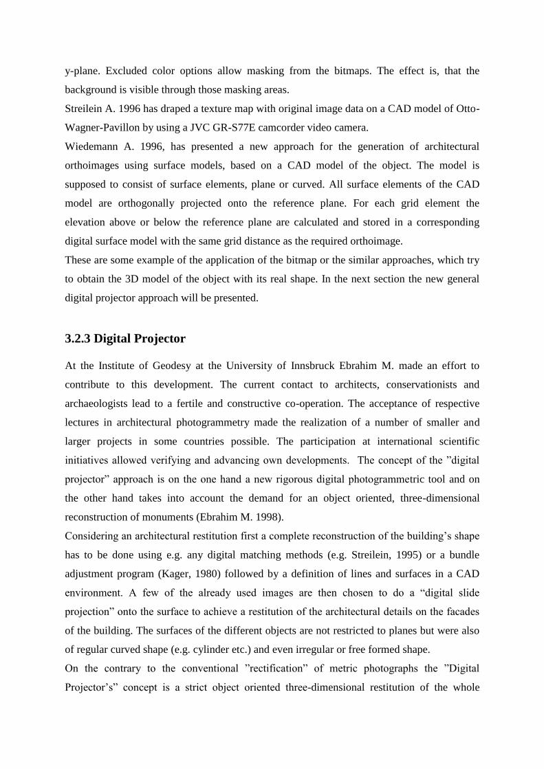
inner walls. Figure (6) illustrates the scheme of the approach, which shows the system of the
data flow from data acquisition to the final virtual 3D-computer model.
Fig.(6) The approach data flow scheme
Using this approach any measurements of any details on the facades can be done easily. No
detail of the object can be neglected, none can be forgotten, and no prior filtering of details
has preceded this using. The full information of the original photos is available in the results.
The accuracy that can be achieved is mainly correlated to the particular of details on the
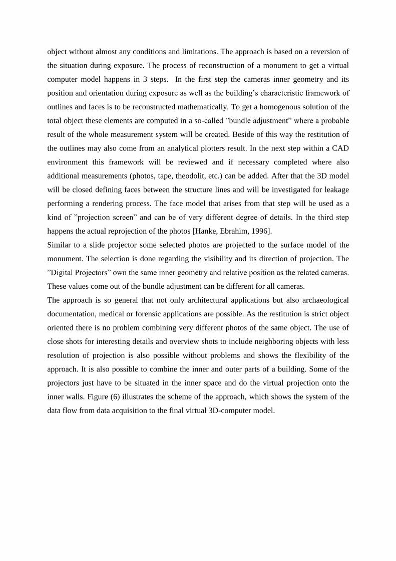
geometric reconstruction of the surface. Figure (7) shows the projection system.
Fig. (7) The projection system.
3.3 Visualization Tools for the Documented World Heritage
3.3.1 Introduction
There are a lot of visualization methods, which show the results of the documented world
heritage. These tools are different, they can be in two dimensions or three dimension, static or
dynamic. In case of two dimensions as example, they can be as true color image, shaded
model image, or rendered model image. In case of three dimensions, they can be as wireframe
(DXF file), or virtual reality model (VRM). Animation is a moved two dimension images in
sequence. Every type of these visualization tools has some special different file format.
3.3.2 Images
Image as defined by Murray and VanRyper, 1994 is a visual representation of graphics data
displayed on the display surface of an out put device. It consists of a sequence of pixels,
which have their gray values. Each pixel has its co-ordinates in relation to the image frame.
The resolution of an image is the measure of detail within an image. The resolution of an
image is its physical size (number of pixels wide by number of scan lines long). The
resolution of a display is the number of scans lines it may display.
Images as results of close range photogrammetry can be orthoimages or perspective images.
In orthoimages one can take a measurements in two dimensions, but a perspective image is
just a visualization tool and one cannot take a measurement from it.
Images have a lot of graphics file format, which is the definition of a file structure used for the
storage of graphics data. As example of the image file format: bmp, jpg, gif, tag, tif... A full
description for these formats is given in Murray and vanRyper, 1994.
3.3.3 DXF Files
It is a vector format files, which designed with vector data, interchange in mind but is vendor-
controlled and originated as a format supporting a single application. In addition DXF was
specifically tailored for CAD information useful in the construction of mechanical, electrical,
and architectural drawings. DXF therefore supports not only common vector elements such as
circles and polygons, but also complex objects frequently used in CAD renderings, such as
three-dimensional objects, and hatching. Each DXF consists of five sections: a header; tables;
blocks; entities sections and an end-of-file marker.
DXF files are very good tools to show the 3-dimension wireframe because they contains the
lines and points in three dimension co-ordinates. Because these files contain also the data of
the surfaces between the points, rendering and shading can be done to show the surfaces of
the 3-dimension model.
3.3.4 Animations
Animation formats have been around for some time. The basic idea is that of the flip-books
you played with as a kid. Rapidly display one image superimposed over another to make it
appear as if the objects in the image are moving. Very primitive animation formats store
entire images that are displayed in sequence, usually in a loop. Slightly more advanced
formats store only a single image, but multiple color maps for the image. By loading in a new
color map, the colors in the image change, and the objects appear to move. Advanced
animation formats store only the differences between two adjacent images (called frames) and
update only the pixels that have actually changed as each frame is displayed. A display rate of
10-15 frames per second is typical for cartoon-like animation. Video animation usually
requires a display rate of 20 frames per second or better to produce a smoother motion.
By using animation as a visualization tool, one can show the objects from different direction
and from different point of views. It runs automatically as one construct the frames and we
cannot control the motion of the object through displaying. We can walk around or fly over
the object as we want, but we have to construct the frames first from the point of view, which
we want.
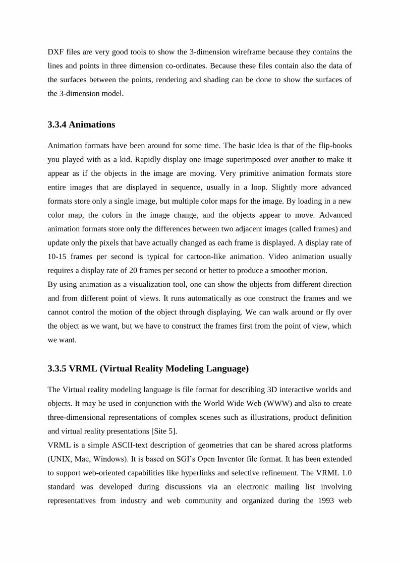
3.3.5 VRML (Virtual Reality Modeling Language)
The Virtual reality modeling language is file format for describing 3D interactive worlds and
objects. It may be used in conjunction with the World Wide Web (WWW) and also to create
three-dimensional representations of complex scenes such as illustrations, product definition
and virtual reality presentations [Site 5].
VRML is a simple ASCII-text description of geometries that can be shared across platforms
(UNIX, Mac, Windows). It is based on SGI’s Open Inventor file format. It has been extended
to support web-oriented capabilities like hyperlinks and selective refinement. The VRML 1.0
standard was developed during discussions via an electronic mailing list involving
representatives from industry and web community and organized during the 1993 web
conference. The first VRML browser, WebSpace, was unveiled during the 1995 web
conference in Darmstadt, Germany [Site 6].
VRML has been designed to fulfill the following requirements:
- Authorability: make it possible to develop application generators and editors, as well as to
import data from other industrial formats.
- Completeness: provide all information necessary for implementation and address a complete
feature-set for wide industry acceptance.
- Composability: the ability to use elements of VRML in combination and thus allow re-
usability.
-Extensibility: the ability to add new elements.
- Implementability: capable of implementation on a wide range of systems.
- Multi-user potential: should not preclude the implementation of multi-user environments.
- Orthogonality: the elements of VRML should be independent of each other, or any
dependencies should be structured and well defined.
- Performance: the elements should be designed with the emphasis on interactive
performance on a variety of computing platforms.
- Scalablity: the elements of VRML should be designed for infinitely large compositions.
- Standard Practice: only those elements that reflect existing practice, that are necessary to
support existing practice, or that are necessary to support proposed standards should be
standardized.
- Well-structured: an element should have a well-defined interface and a simply stated
unconditional purpose. Multipurpose elements and side effects should be avoided.
In VRML file, one can control his moving through or around the 3-dimensional objects.
VRML files can be with texture or without. There is a lot of software, which produce a
VRML files, and in the other hand there is a lot of browsers, which can browse a VRML.
Each of these browsers is different from the others in some facility, but all of them have the
ability to walk through and around the objects or fly over them.
The big advantage of VRML files that one can control his moving by the mouse to show
every details in the objects and this gives him the ability to make zoom to the object or show
it from a distance. This is a big difference between the animation and VRML, while animation
is run automatically depending on the already defined frames and the moving path of the
frame creating tool. Also there is another big and important difference between animation and
VRML that animation is a two-dimensional environment, but VRML is a three-dimensional
environment.
3.4 Examples of the Documented World Heritage
As mentioned before the photogrammetry has a wide range of applications in the field of
documenting the world heritage. There are a lot of examples, which demonstrate the powerful
of the photogrammetric technique for such applications. In the next sections, some of the
applications of the digital photogrammetry in the field of world heritage documentation will
be presented.
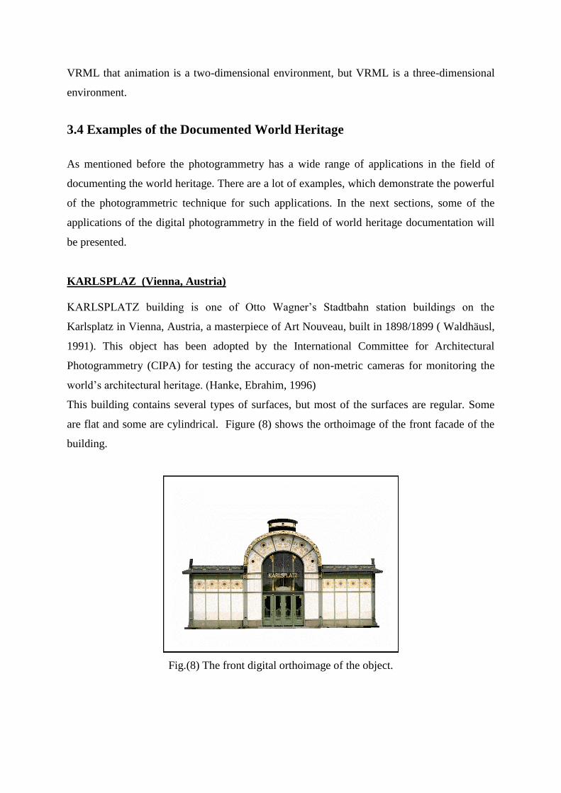
KARLSPLAZ (Vienna, Austria)
KARLSPLATZ building is one of Otto Wagner’s Stadtbahn station buildings on the
Karlsplatz in Vienna, Austria, a masterpiece of Art Nouveau, built in 1898/1899 ( Waldhäusl,
1991). This object has been adopted by the International Committee for Architectural
Photogrammetry (CIPA) for testing the accuracy of non-metric cameras for monitoring the
world’s architectural heritage. (Hanke, Ebrahim, 1996)
This building contains several types of surfaces, but most of the surfaces are regular. Some
are flat and some are cylindrical. Figure (8) shows the orthoimage of the front facade of the
building.
Fig.(8) The front digital orthoimage of the object.
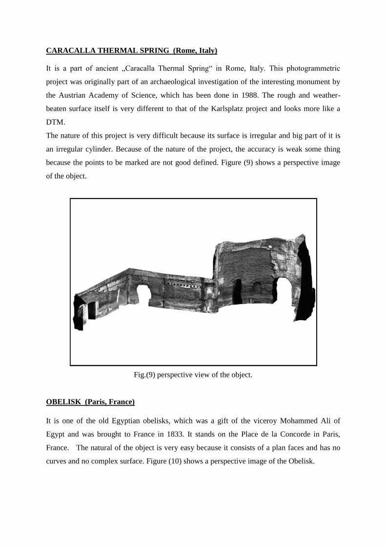
CARACALLA THERMAL SPRING (Rome, Italy)
It is a part of ancient „Caracalla Thermal Spring“ in Rome, Italy. This photogrammetric
project was originally part of an archaeological investigation of the interesting monument by
the Austrian Academy of Science, which has been done in 1988. The rough and weather-
beaten surface itself is very different to that of the Karlsplatz project and looks more like a
DTM.
The nature of this project is very difficult because its surface is irregular and big part of it is
an irregular cylinder. Because of the nature of the project, the accuracy is weak some thing
because the points to be marked are not good defined. Figure (9) shows a perspective image
of the object.
Fig.(9) perspective view of the object.
OBELISK (Paris, France)
It is one of the old Egyptian obelisks, which was a gift of the viceroy Mohammed Ali of
Egypt and was brought to France in 1833. It stands on the Place de la Concorde in Paris,
France. The natural of the object is very easy because it consists of a plan faces and has no
curves and no complex surface. Figure (10) shows a perspective image of the Obelisk.
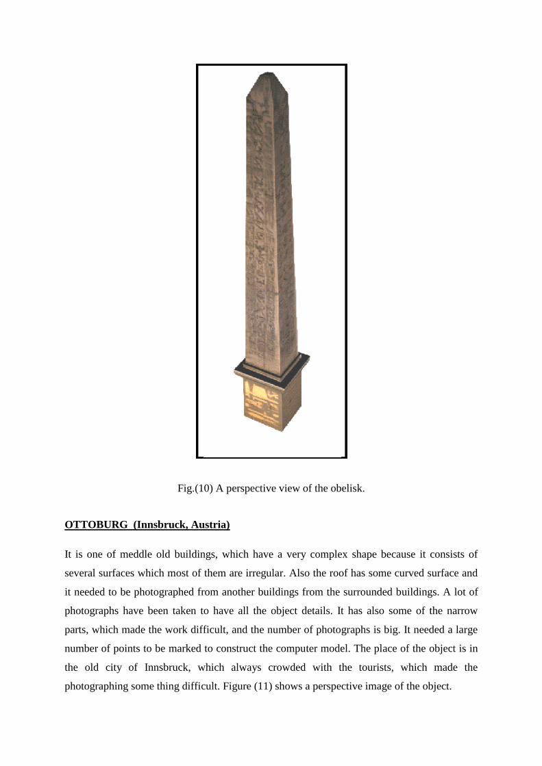
Fig.(10) A perspective view of the obelisk.
OTTOBURG (Innsbruck, Austria)
It is one of meddle old buildings, which have a very complex shape because it consists of
several surfaces which most of them are irregular. Also the roof has some curved surface and
it needed to be photographed from another buildings from the surrounded buildings. A lot of
photographs have been taken to have all the object details. It has also some of the narrow
parts, which made the work difficult, and the number of photographs is big. It needed a large
number of points to be marked to construct the computer model. The place of the object is in
the old city of Innsbruck, which always crowded with the tourists, which made the
photographing some thing difficult. Figure (11) shows a perspective image of the object.
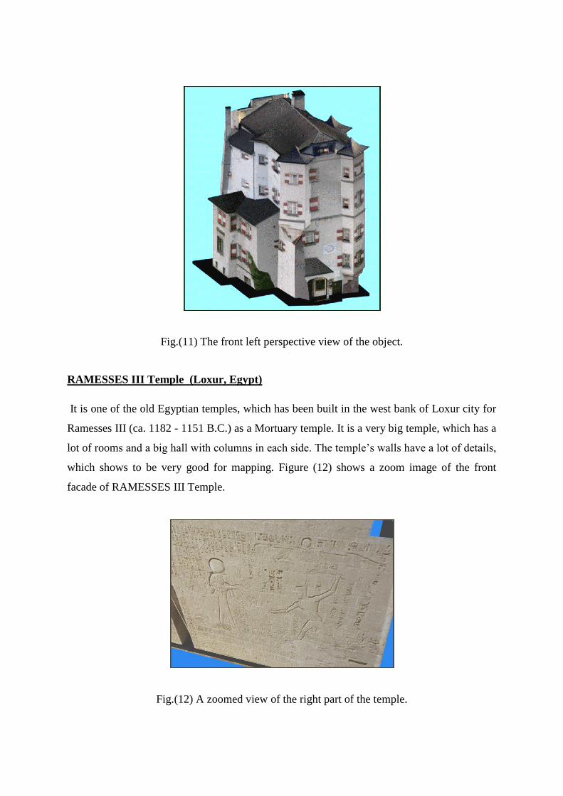
Fig.(11) The front left perspective view of the object.
RAMESSES III Temple (Loxur, Egypt)
It is one of the old Egyptian temples, which has been built in the west bank of Loxur city for
Ramesses III (ca. 1182 - 1151 B.C.) as a Mortuary temple. It is a very big temple, which has a
lot of rooms and a big hall with columns in each side. The temple’s walls have a lot of details,
which shows to be very good for mapping. Figure (12) shows a zoom image of the front
facade of RAMESSES III Temple.
Fig.(12) A zoomed view of the right part of the temple.
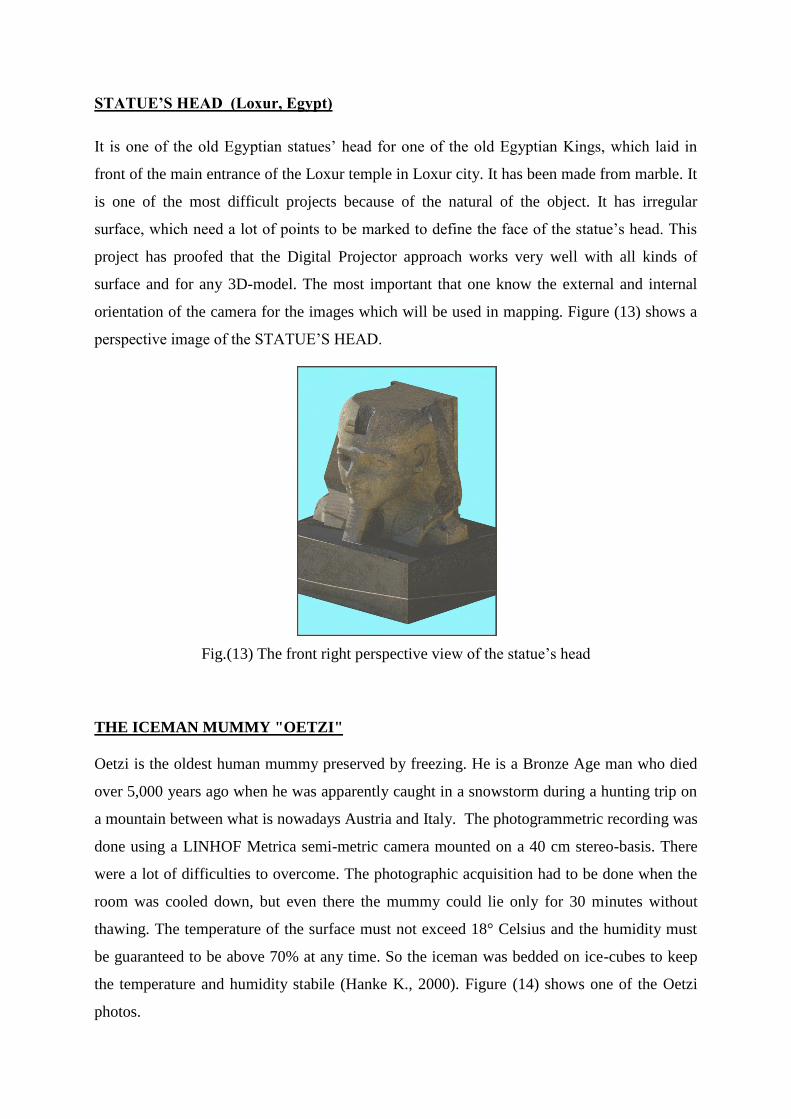
STATUE’S HEAD (Loxur, Egypt)
It is one of the old Egyptian statues’ head for one of the old Egyptian Kings, which laid in
front of the main entrance of the Loxur temple in Loxur city. It has been made from marble. It
is one of the most difficult projects because of the natural of the object. It has irregular
surface, which need a lot of points to be marked to define the face of the statue’s head. This
project has proofed that the Digital Projector approach works very well with all kinds of
surface and for any 3D-model. The most important that one know the external and internal
orientation of the camera for the images which will be used in mapping. Figure (13) shows a
perspective image of the STATUE’S HEAD.
Fig.(13) The front right perspective view of the statue’s head
THE ICEMAN MUMMY "OETZI"
Oetzi is the oldest human mummy preserved by freezing. He is a Bronze Age man who died
over 5,000 years ago when he was apparently caught in a snowstorm during a hunting trip on
a mountain between what is nowadays Austria and Italy. The photogrammetric recording was
done using a LINHOF Metrica semi-metric camera mounted on a 40 cm stereo-basis. There
were a lot of difficulties to overcome. The photographic acquisition had to be done when the
room was cooled down, but even there the mummy could lie only for 30 minutes without
thawing. The temperature of the surface must not exceed 18° Celsius and the humidity must
be guaranteed to be above 70% at any time. So the iceman was bedded on ice-cubes to keep
the temperature and humidity stabile (Hanke K., 2000). Figure (14) shows one of the Oetzi
photos.
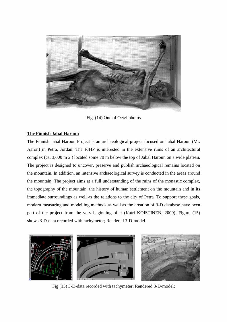
Fig. (14) One of Oetzi photos
The Finnish Jabal Haroun
The Finnish Jabal Haroun Project is an archaeological project focused on Jabal Haroun (Mt.
Aaron) in Petra, Jordan. The FJHP is interested in the extensive ruins of an architectural
complex (ca. 3,000 m 2 ) located some 70 m below the top of Jabal Haroun on a wide plateau.
The project is designed to uncover, preserve and publish archaeological remains located on
the mountain. In addition, an intensive archaeological survey is conducted in the areas around
the mountain. The project aims at a full understanding of the ruins of the monastic complex,
the topography of the mountain, the history of human settlement on the mountain and in its
immediate surroundings as well as the relations to the city of Petra. To support these goals,
modern measuring and modelling methods as well as the creation of 3-D database have been
part of the project from the very beginning of it (Katri KOISTINEN, 2000). Figure (15)
shows 3-D-data recorded with tachymeter; Rendered 3-D-model
Fig (15) 3-D-data recorded with tachymeter; Rendered 3-D-model;
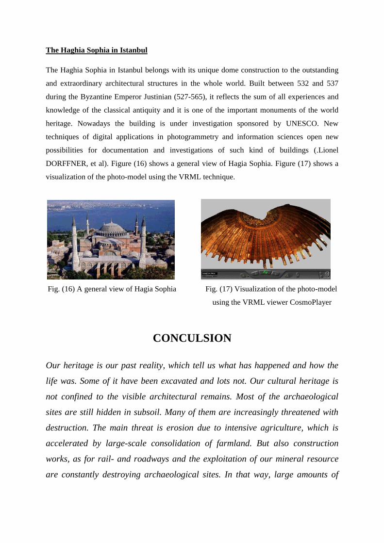
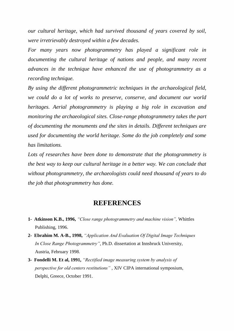
The Haghia Sophia in Istanbul
The Haghia Sophia in Istanbul belongs with its unique dome construction to the outstanding
and extraordinary architectural structures in the whole world. Built between 532 and 537
during the Byzantine Emperor Justinian (527-565), it reflects the sum of all experiences and
knowledge of the classical antiquity and it is one of the important monuments of the world
heritage. Nowadays the building is under investigation sponsored by UNESCO. New
techniques of digital applications in photogrammetry and information sciences open new
possibilities for documentation and investigations of such kind of buildings (.Lionel
DORFFNER, et al). Figure (16) shows a general view of Hagia Sophia. Figure (17) shows a
visualization of the photo-model using the VRML technique.
Fig. (16) A general view of Hagia Sophia Fig. (17) Visualization of the photo-model
using the VRML viewer CosmoPlayer
CONCULSION
Our heritage is our past reality, which tell us what has happened and how the
life was. Some of it have been excavated and lots not. Our cultural heritage is
not confined to the visible architectural remains. Most of the archaeological
sites are still hidden in subsoil. Many of them are increasingly threatened with
destruction. The main threat is erosion due to intensive agriculture, which is
accelerated by large-scale consolidation of farmland. But also construction
works, as for rail- and roadways and the exploitation of our mineral resource
are constantly destroying archaeological sites. In that way, large amounts of
our cultural heritage, which had survived thousand of years covered by soil,
were irretrievably destroyed within a few decades.
For many years now photogrammetry has played a significant role in
documenting the cultural heritage of nations and people, and many recent
advances in the technique have enhanced the use of photogrammetry as a
recording technique.
By using the different photogrammetric techniques in the archaeological field,
we could do a lot of works to preserve, conserve, and document our world
heritages. Aerial photogrammetry is playing a big role in excavation and
monitoring the archaeological sites. Close-range photogrammetry takes the part
of documenting the monuments and the sites in details. Different techniques are
used for documenting the world heritage. Some do the job completely and some
has limitations.
Lots of researches have been done to demonstrate that the photogrammetry is
the best way to keep our cultural heritage in a better way. We can conclude that
without photogrammetry, the archaeologists could need thousand of years to do
the job that photogrammetry has done.
REFERENCES
1- Atkinson K.B., 1996, “Close range photogrammetry and machine vision”, Whittles
Publishing, 1996.
2- Ebrahim M. A-B., 1998, “Application And Evaluation Of Digital Image Techniques
In Close Range Photogrammetry”, Ph.D. dissertation at Innsbruck University,
Austria, February 1998.
3- Fondelli M. Et al, 1991, “Rectified image measuring system by analysis of
perspective for old centers restitutions” , XIV CIPA international symposium,
Delphi, Greece, October 1991.
4- Georgopoulos A and Tournas E., 1994, “Digital rectification using a PC”,
International archive of photogrammetry and remote sensing, Melbourne, Australia,
March, 1994
5- Hanke K.and Ebrahim M. A-B., 1996, “A general approach for object oriented 3D-
mapping in digital close range photogrammetry” , International archive of
photogrammetry and remote sensing, Vol. XXXI, Part B5, Vienna, Austria, 1996.
6- Hanke K., 2000, “The Photogrammetric Contribution To Archaeological
Documentation Of Prehistory”, International Archives Of Photogrammetry And
Remote Sensing, Volum XXXIII, part B5/1, Amsterdam, July 2000.
7- Hottier Ph., 1976, “Accuracy of close range analytical restitution: practical
experiments and prediction”, Photogrammetric engineering and remote sensing, 42,
(3), 1976
8- Kager H., 1980, “Das interaktive Programmsystem ORIENT im Einsatz”,
International archive of photogrammetry, Hamburg, Vol. XXIII/5 1980.
9- Karara H.K., 1989, “Non-topographic photogrammetry”,American society of
photogrammetry, second edition, 1989.
10- Katri KOISTINEN, 2000, “3d Documentation For Archaeology During Finnish
Jabal Haroun Project”, International Archives Of Photogrammetry And Remote
Sensing, Volum XXXIII, part B5/1, Amsterdam, July 2000
11- Kenji Hongo, Ryuji Matsuoka, Seiju Fujiwara, Katsuhiko Masuda, and Shigeo
Aoki, 2000, “Development Of Image-Based Information System For Restoration Of
Cultural Heritage”, International Archives Of Photogrammetry And Remote Sensing,
Volum XXXIII, part B5/1, Amsterdam, July 2000
12- Lionel DORFFNER, Karl KRAUS, Josef TSCHANNERL, Orhan ALTAN ,
Sitki KـLـR, and G ِ nül TOZ , 2000, “Hagia Sophia - Photogrammetric Record Of
A World Cultural Heritage”, International Archives Of Photogrammetry And Remote
Sensing, Volum XXXIII, part B5/1, Amsterdam, July 2000.
13- Murray J.D. and VanRyper W., 1994, “Encyclopaedia of graphics file formats”,
O’Reilly & Associates, Inc., First edition, 1994.
14- Papo H.B., 1982, “Free net analysis in close range photogrammetry”,
Photogrammetric engineering and remote sensing, 48, (4), 1982
15- Patias P., 1991, “Architectural photogrammetry goes to the digital darkroom”, XIV
CIPA international symposium, Delphi, Greece, October 1991.
16- Peter Waldhaeusl, 1997, “Mass-Documentation of Architecture and its Environment
Objective and Tasks for CIPA and its Working Groups”, CIPA international
Symposium, volum XXXII, Part C1B, Goeteborg, Sweden, October 1997.
17- Petros PATIAS ,Juergen PEIPE, 2000, “Photogrammetry And Cad/Cam In
Culture And Industry - An Ever Changing Paradigm”, International Archives Of
Photogrammetry And Remote Sensing, Volum XXXIII, part B5/2, Amsterdam, July
2000..
18- Petros Patias, Aristotle University of Thessaloniki, 2002, “A Low-Cost, 3D-
Visualization and Measuring Tool in the Service of Archaeological Excavations”,
Computer Applications and Quantitative Methods in Archaeology Conference, CAA,
"The Digital Heritage of Archaeology", Heraklion, Crete, Greece, 2-6 April, 2002,
[Site: http://www.caa2002.gr/abstracts_papers/36.html]
19- Pomaska G., 1996, “Implementation of digital 3D-models in building surveys based
on multiimage photogrammetry”, International archive of photogrammetry and
remote sensing, Vol XXXI, part B5, Vienna, Austria 1996.
20- Sanjib K., 1988, “Analytical photogrammetry”, Pergamon Press, second edition,
1988
21 - Simone da SILVA * , Quintino DALMOLIN, 2000, “Recording Of Historical
Monuments For Mono-Differential Restitution”, International Archives Of
Photogrammetry And Remote Sensing, Volum XXXIII, part B5/1, Amsterdam, July
2000.
22- Slama C., 1980, “Manual of Photogrammetry”, American society of
photogrammetry, forth edition, 1980.
23- Streilein A., 1995, “Videogrammetry and CAAD for arcitectural restitution of Otto-
Wagner-Pavillion in Vienna”.
24- Torlegard K., 1976, “Stat-of-the-art of close range photogrammetry”,
Photogrammetric engineering and remote sensing, 42, (1), 1976
25- Torlegard K., 1981, “Development of non-topographic photogrammetry and its
future”, Paper presented at the fifth anniversary meeting of the Finnish society of
photogrammetry on Sept. 25, 1981.
26- Wolf P.R., 1974, “Element of photogrammetry”, Mc-Grew Hill Kogakusha, Ltd,
1974
[Site 1] http://define.ansme.com/words/a/archaeology.html
[Site 2] http://www.geocities.com/Griffinlady/papers/theory/archaeology.html
[Site 3] http://www.univie.ac.at/Luftbildarchiv/wgv/intro.htm
[Site 4] http://www.univie.ac.at/Luftbildarchiv/intro/aa_hist.htm

[Site 5] http://vrml.sgi.com /moring-worlds /spec /part1 /introduction.html
[Site 6] http://vag.vrml.org /vrml2.0 /final /spec /index.html
[Site 7] http://www.univie.ac.at/Luftbildarchiv/wgv/appl.htm
[Site 8] http://www.unesco.org/general/eng/about/what.shtml
[Site 9] http://cipa.icomos.org/wgroups.html
[Site 10] http://www.international.icomos.org/about.htm
[Site 12] http://www.univie.ac.at/Luftbildarchiv/intro/aa_aaint.htm