Embed Size (px)
DESCRIPTION
Â
Citation preview

RESEARCH


N
S
EW
N
S
W E
N
S
W E
WINTER WINDS
SUMMER WINDS
Existing Site Conditions
The proposed site sits in Roxbury and is owned by the Boston Water and Sewer Commission nearby. In a dense urban area such as this, it is important to consider what kind of effect buildings have on their neighbors. The first objective of the Site and Ecology team was to analyze existing solar and wind conditions and climate data around the proposed site. Using this data, the team then illustrated scenarios using eight basic housing typologies and solar information to demonstrate fundamental active and passive strategies for maximizing daylight exposure and responding to local wind patterns.
Existing Site
This diagram illustrates the position of the sun at 12:00
pm on the summer solstice. At noon, the sun is at an angle
of 70 degrees from the ground and rises 60 degrees east
of true north. Rooms with larged glazed areas facing
the northeastern edge of the site would run the risk of
overheating in the hot summer sun.
At 12:00 pm on the winter solstice, the sun is at an angle of
25 degrees from the ground and rises 120 degrees east of
true north. Ideally, buildings on the site would have some
glazing oriented towards the southeast corner of the site
so as to passively heat rooms using the winter midday sun.
Winds in June, July, and August typically blow northwest
and west from the Atlantic Ocean and are necessary for
providing passive ventilation during these hot and humid
months. Winter winds blow down faster, colder, and more
frequently in a southeast direction, so positioning buildings
with perimeters on the north and west edges of the site
would help to block the surrounding open spaces from
bitter winds.
Winter Sun (Dec 21) Prevailing Winds, Summer + WinterSummer Sun (Jun 21)
32

Solar Radiation
The solar radiation map illustrates the annual surface irradiation based on Boston’s climate. The warmest colors represent the most concentrated irradiation. The cooler colors receive less sunlight and show areas with less irradiation. The amount of usable solar energy shown in this map can be utilized for passive heating strategies, especially flat panel photovoltaics.
The map shows a high potential for collecting solar energy in this area. Boston takes advantage of this byimplementing this renewable energy strategy in many of its buildings. Across the street from the site even, the Boston Water & Sewer Commission takes advantage of the solar energy through a roof mounted solar panel system.
Solar Envelope
The solar envelopes depicted in the diagrams to the right represent the ideal volume for a building on the site so as not to shade the surrounding buildings. The parameters used in generating this visualization include input for the shape of the lots, the range of daylight hours desired, and the latitude (42 degrees).
When the daylight hours is set to 11-1 pm, it is clear that the majority of the building’s mass should be concentrated on the southwest corner of the site so as to mitigate shading. At the 2-4 pm position, however, the solar envelope is nearly flat. It would be impossible to build anything within that volume. The information drawn from this study is that a building can be designed on the site in such a way that it does not shade the surrounding area at midday, it will still end up putting other buildings in shadow during the mid- to late afternoon.
Individual lots, 2-4 pm Individual lots, 11-1 pm
Entire site, 11-1 pm
1500135012001050900750600450300150
0
kWhm-2
N
54

Solar Fan
The solar fan takes the desired open space of a design and projects a volume demonstrating the area that needs to be kept clear to minimize shade on the open space. The solar fan helps to determine the cuts on our ideal masses that would allow for adequate sunlight on the outdoor spaces created on the site.
The parameters used in generating this visualization include input for the shape of the open space, average first frost (October 1st), latitude (42 degrees) and the desired amount of sunlight per day (4 hours for the purposes of our study). The first frost date defines when solar access is most critical for open spaces for purposes of passive heating.
The example to the right illustrates solar fans in light red. The dark red portions are where the solar fan cuts into the proposed building masses.
“L”
“U”
Carved block “Z”
“T”
Perimeter block
Carved block with point block Bar
Typologies
Massing scenarios were tested on the 4 plots of the site using 8 general forms common to many contemporary housing projects. Each typology was designed to a floor area ratio of 3 and a maximum height of 70 feet. Masses consisting of double loaded corridoors were set at 60 feet wide and single loaded at 30 feet wide. After each scheme of typologies was configured, the solar fan was calculated to determine what massing changes should be made to the buildings to maximize daylighting. The schemes were then reimagined to take advantage of daylighting as a passive strategy.
76

Typology Trial, Scheme 1
Because the courtyards in the western and northern quardrants are large and open and the buildings are 70’ tall, the solar fan cuts in Step 2 are significant.
The U shaped volume in the southern quardrant would not be feasible due to low FAR, but the L and T shaped volumess could be modified to have wider, lower bars. Ultimately, it is important to striking a balance between the size of the courtyard and the proportions of the bar.
The edge formed on the northern quadrant begins to block winter winds from the northwest.
Step 1, Pure Volume Step 2, Solar Fan Cut
Step 4, Revised VolumeStep 3, Remaining Volume
Solar fan
Cuts made by solar fan
Typology Trial, Scheme 2
Step 1, Pure Volume Step 2, Solar Fan Cut
Step 4, Revised VolumeStep 3, Remaining Volume
Once again, the volumes that fully enclose their courtyards are most impacted by the solar fan cuts. Notice that the L volume on the northern quadrant is the same height as the perimeter block on the western quadrant but is less affected by the solar fan. The smaller perimeter blocks have smaller courtyards but are also strongly affected by the solar fan.
98

The solar fan cut shown in Step 2 requires moderate edits to each volume. The perimeter block on the north quadrant and the U volume on the east quadrant are edited down to one or two levels, far below the required FAR of 3.
The small carved block on the southern quadrant is not likely to be feasible design option, as its edited form in Step 4 would be difficult to design units for.
If one were to design their site based on the solar data provided, a perimeter type such as the U would only be feasible if it was low to the ground and with wider proportions like the building on the western quadrant.
Typology Trial, Scheme 3
Step 1, Pure Volume Step 2, Solar Fan Cut
Step 4, Revised VolumeStep 3, Remaining Volume
Step 3, Remaining Volume
Typology Trial, Scheme 4
Step 1, Pure Volume Step 2, Solar Fan Cut
Step 4, Revised VolumeStep 3, Remaining Volume
In the fourth scheme, the largest cuts are made on the T and U volumes due to their height and the size of the courtyards. It becomes apparent that it is not feasible for these large courtyards to have sun for four hours a day without shade. The northernmost open space is also exposed to prevailing winds from the northwest during the winter time. The designer must either accept shaded courtyards that are colder and less appealing, or scale them down.
The carved blocks are less impacted by the solar fan, but this is admittedly a less common housing typology, and the designer may face challenges with units getting
1110

Typology Trial, Scheme 5
Step 1, Pure Volume Step 2, Solar Fan Cut
Step 4, Revised VolumeStep 3, Remaining Volume
Typology Trial, Scheme 6
Step 1, Pure Volume Step 2, Solar Fan Cut
Step 4, Revised VolumeStep 3, Remaining Volume
The scheme forms one large courtyard between the volumes on the northern and western quadrants. Like the previous scheme, building up the northeastern edge is working well and the mirrored version becomes lower to accommodate solar access as the sun moves westward across the sky.
This scheme begins to find a solution on the northern quadrant. The massive bar on its northeastern edge is working well but the smaller extrusion coming off of it is significantly eroded by the solar fan because the open space on either side of it are of considerable size. The southern edge of both the eastern and southern quadrants are eroded to allow for daylighting during the winter months and for wind during the summer months.
1312

Typology Trial, Scheme 7
Step 1, Pure Volume Step 2, Solar Fan Cut
Step 4, Revised VolumeStep 3, Remaining Volume
In this scheme, the open spaces are nearing their optimal size; the building heights are under 40 feet, and because of this the solar fans are less intrusive. The east-west orientation of the bar volumes on the northern quadrant also allow for maximum daylighting as the sun moves across the sky. The southern quadrant experiments with a “Z” typology. Ultimately it is not feasible on the smaller plots because the required height for this volume to reach the FAR of 3 casts too much shadow onto the smaller, divided open spaces. Not only that, but this volume is configured as a 30’ wide single loaded building — less than ideal for designing and placing residential units.
Typology Trial, Scheme 8
Step 1, Pure Volume Step 2, Solar Fan Cut
Step 4, Revised VolumeStep 3, Remaining Volume
The final scheme follows the success of the previous scheme by deploying the strategy of low, east-west bars in the western quadrant while continuing to open spaces divided. The “U” shaped volume on the southern quadrant is taller than the ideal of the other quadrants, but it is still moderately successful because its opening is oriented towards the south to for daylighting during the winter months.
1514

Design Recommendations Environmentally Driven
Design recommendations fall under two categories: ‘Standard Driven’ and ‘Environmentally Driven.’
‘Environmentally Driven’ recommendations are based on ideal open spaces and solar orientation. The priority of these recommendations is to maximize solar energy and daylighting potential.
‘Standard Driven’ recommendations stem from set requirements for residential buildings. Realistic building dimensions and FAR are the parameters used to make these types of conclusions. The FAR used is 3 with a maximum building height of 70’. Building widths used are either 30’ for a single loaded corridor and 60’ for a double loaded corridor.
W
E
Build up the northeastern edge of the site. This applies to
the northern and eastern quadrants. Buildings here can be
taller and wider forming an edge on the site that won’t eat
into the daylight of the open spaces.
Build Up Orient East-West
The larger northern and western quadrants of the site
work best when there are fragmented open spaces with
lower buildings rather than taller buildings with larger
more vast open spaces. Bar buildings are good options for
this strategy because they can be repeated uniformly to
form the proper series of outdoor spaces with adequate
day lighting. Placement of these masses will work best in
an east to west bar orientation to give the majority of the
masses exposure to southern light.
The smaller plots on the southern and eastern quadrants
of the site work best with one large open space. Lower
masses work better here too which, through the FAR,
result in wider, double loaded typologies as favorable
choices. This shortening also opens up the site as whole to
further exposure to the south.
At 12:00 pm on the winter solstice, the sun is at an angle of
25 degrees from the ground and rises 120 degrees east of
true north. Ideally, buildings on the site would have some
glazing oriented towards the southeast corner of the site
so as to passively heat rooms using the winter midday sun.
Divide the Open Spaces Open the Southern EdgeForm a Singular Open Space
The perimeter blocks generally do not work and in many
cases were cut away turning them into more of a “U”
type mass. Ideally the “U” typologies work best when
opening up to the south for exposure to summer winds and
southern light.
1716

Design Recommendations Standard Driven
Certain typologies are not possible at all because of the
FAR of 3 combined with the set height limit of 70’. The
carved block typology typically doesn’t work. The small
series of enclosed interior courtyards as open spaces
cannot function properly in terms or area or day lighting.
For residential buildings, this typology is also unrealistic
and doesn’t create the space required for repetitive
apartment units to fit inside of it.
Singular bar typologies are not feasible on the site either.
When working within the requirements, the masses simply
become too tall. This applies both for double and single
loaded bars.
Height Restrictions Designable DimensionsFeasible Widths
When working with the set FAR, keeping the masses lower
and wider tends to work better than narrow and tall. This
strategy allows for more sunlight to enter the site and for
less shading onto other buildings.
1918

PROTOTYPE

AGGREGATION_CONCEPT DIAGRAMARCH 5110 URBAN HOUSING
EMILY WEISER

SECTION AXONARCH 5110 URBAN HOUSING
EMILY WEISER
STUDIOS1 BEDSAMENITIESPARKCIRCULATIONPARKING
14,400 GSF28,750 GSF2,825 GSF5,345 GSF14,600 GSF15,000 GSF

BUILDING AXONARCH 5110 URBAN HOUSING
6.5 stories, single loaded corridor building32 studios (40%)46 1 bedrooms (60%)70,920 GSFFAR: 4.73Lot coverage ratio: .72
EMILY WEISER

GROUND FLOOR PLANARCH 5110 URBAN HOUSING
EMILY WEISER

FLOOR PLAN LEVEL 3ARCH 5110 URBAN HOUSING
10,380 GSF/typical floor7,700 ASF/typical floor
EMILY WEISER

UNIT FLOOR PLANSARCH 5110 URBAN HOUSING
EMILY WEISER
STUDIO450 SF32 UNITS
1 BEDROOM625 SF46 UNITS
10’ 25’ 50’
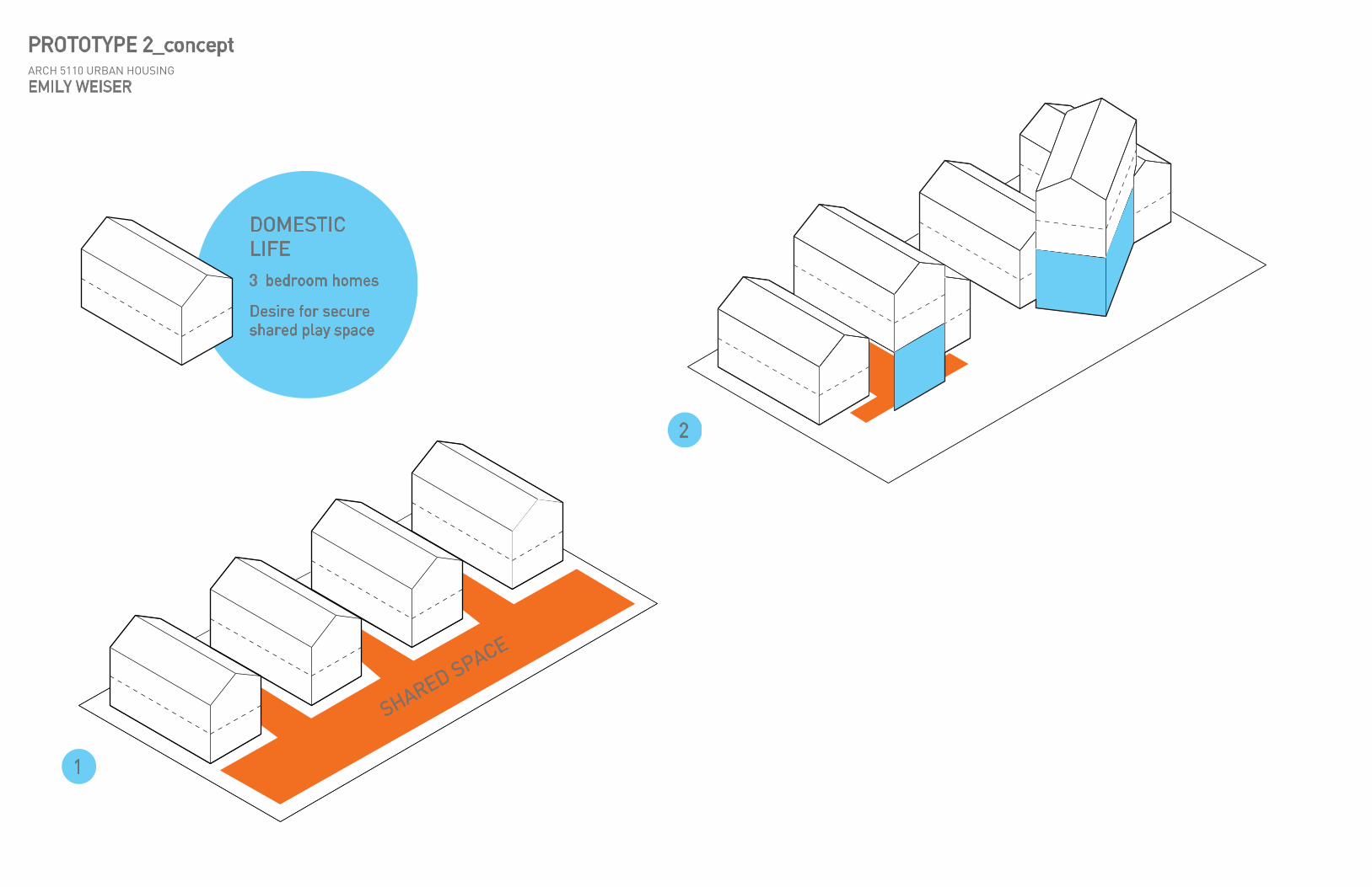
PROTOTYPE 2_conceptARCH 5110 URBAN HOUSING
EMILY WEISER
DOMESTIC LIFE
1
2
3 bedroom homes
Desire for secure shared play space

STAIR
THREE LEVELS

25’-10”
19’-4” 21
’-8”
17’-0”
770 ASF

MID REVIEW


CITY AND SUBURB BLOCK STUDY
NORTH END
SOUTH END
ROXBURY
& BEYOND
NORTH END
SOUTH END
ROXBURY
& BEYOND

BLOCK STUDY OF THE VILLAGE
LAYER:Urban perimeter block
LAYER:Urban rowhouse
UNIT and shared open space

PARKING LOTS ARE THE ONLY THING SHARED.
IS OUR BACKYARD SECURE?
UNPROGRAMMED GREEN SPACE = UNTAPPED POTENTIAL.
WHAT IS THE STATE
OF FAMILY-ORIENTED
HOUSING IN BOSTON?

PROGRAM AXONHOUSING MID REVIEWEMILY WEISER

TRANSVERSE SECTIONHOUSING MID REVIEWEMILY WEISER

TYPICAL UNIT PLANS HOUSING MID REVIEWEMILY WEISER
THREE BEDROOM (A)900 SF26 3BED UNITS TOTAL (20%)
THREE BEDROOM (B)1,125 SF


BLOCK STUDY
LAYER:Urban perimeter block
LAYER:Exterior corridor and communal spaces UNIT and shared space


TRANSVERSE SECTIONHOUSING MID REVIEWEMILY WEISER

TYPICAL UNIT PLANS HOUSING MID REVIEWEMILY WEISER
STUDIO450 SF64 UNITS (48%)
ONE BEDROOM570 SF26 UNITS (20%)
TWO BEDROOM710 SF16 UNITS (12%)

LONGITUDINAL SECTIONHOUSING MID REVIEWEMILY WEISER

GROUND FLOOR SITE PLANHOUSING MID REVIEWEMILY WEISER

SECOND FLOOR PLANHOUSING MID REVIEWEMILY WEISER

THIRD + FOURTH FLOOR PLANSHOUSING MID REVIEWEMILY WEISER

FIFTH + SIXTH FLOOR PLANSHOUSING MID REVIEWEMILY WEISER


FINAL REVIEW

HOUSING AND IDENTITY fall 2014

SITE PLAN

RESIDENTIAL FABRICtraditional perimeter housing and alternate urban strategies

���� ��������������������� ���������
��������������������
������������������������������������ ���
EXISTING URBAN ISSUES what’s driving the design?
LACK OF SECURITY
RESIDUAL GREEN SPACE
NO SHARED SPACES

PROCESS DIAGRAM7KH�ȌUVW�VWHS�LV�WR�FRQWURO�SXEOLF�FLUFXODWLRQ�DQG�DFFHVV�WR�WKH�VLWH��&UHDWLQJ�D�SOLQWK�OLPLWV�SXEOLF�DFFHVV�ZKLOH�WKH�FUHDWLRQ�RI�DQ�RSHQ�FRXUW\DUG�LV�LQYLWLQJ�WR�DOO��7KH�DSDUWPHQW�EORFN�HYROYHV�WR�KROG�PRUH�RI�WKH�FRXUW\DUG�ZKLOH�D�VHFRQG�OD\HU�RI�JUHHQ�VSDFH�LV�FUHDWHG�LQ�WKH�SOLQWK��7KH�KRXVLQJ�V\VWHPV�WKHQ�DUH�LQWURGXFHG�DQG�GHYHORSHG�

MASSING STRATEGIESWKH�GRPHVWLF�SURWRW\SH
IDENTITY7KH�PRVW�EDVLF�LGHD�RI�D�KRXVH�ZLWK�LWV�VTXDUH�DSSHDUDQFH�DQG�SLWFKHG�URRI�LV�D�V\PERO�UHSUHVHQWLQJ�KRPH�DQG�LGHDV�RI�FRPIRUW�DQG�VHFXULW\��
URBAN DENSITY7KH�KRXVLQJ�LV�SXVKHG�WR�WKH�SHULPHWHU�DQG�RSHUDWHV�OLNH�GLUHFW�DFFHVV�URZKRXVHV�
DIVERSITY&DUYLQJ�RXW�YROXPHV��UDLVLQJ�EXLOGLQJ�KHLJKWV�FUHDWHV�QHZ�SRLQWV�RI�DFFHVV�DQG�YDULHG�KRXVLQJ�RSWLRQV�

SECTION AXON WKH�URZKRXVH�DQG�VWUHHW�HGJH

MASSING STRATEGIESW\SLFDO�SHULPHWHU�EORFN�GHVLJQ

MASSING STRATEGIESDQ�H[WURYHUWHG�FRUULGRU

MASSING STRATEGIESHPEHGGLQJ�SXEOLF�VSDFHV�LQ�WKH�FRUULGRU

BELOW GRADE PLAN

GROUND FLOOR PLAN

RESIDENTIAL FLOOR PLAN VHFRQG�ȍRRU

UNIT PLAN WKUHH�EHGURRP�URZKRXVH
ȍRRU�RQH
NH\
ȍRRU�WZR

UNIT PLAN WKUHH�EHGURRP�URZKRXVH
ȍRRU�RQH
NH\
ȍRRU�WZR

UNIT PLAN VWXGLR
NH\

UNIT FACADES RQH�VWXGLR��RQH�URZKRXVH
glazing
JUH\�EULFNEULFN�VFUHHQ�ZLWK�JOD]LQJ�EHKLQG
PHWDO�SDQHO

ELEVATION + SECTION

ELEVATION

SECTION

PERSPECTIVE