Embed Size (px)
DESCRIPTION
Arch Dam
Citation preview
CECW-ED
Engineer Manual1110-2-2201
Department of the ArmyU.S. Army Corps of Engineers
Washington, DC 20314-1000
EM 1110-2-2201
31 May 1994
Engineering and Design
ARCH DAM DESIGN
Distribution Restriction StatementApproved for public release; distribution is
unlimited.
DEPARTMENT OF THE ARMY EM 1110-2-2201U.S. Army Corps of Engineers
CECW-EG Washington, DC 20314-1000
ManualNo. 1110-2-2201 31 May 1994
Engineering and DesignARCH DAM DESIGN
1. Purpose. This manual provides information and guidance on the design, analysis,and construction of concrete arch dams.
2. Applicability. This manual applies to HQUSACE elements, major subordinate com-mands, districts, laboratories, and field operating activities (FOA) having civilworks responsibilities.
3. Discussion. This manual provides general information, design criteria andprocedures, static and dynamic analysis procedures, temperature studies, concretetesting requirements, foundation investigation requirements, and instrumentation andconstruction information for the design of concrete arch dams.
FOR THE COMMANDER:
WILLIAM D. BROWNColonel, Corps of EngineersChief of Staff
DEPARTMENT OF THE ARMY EM 1110-2-2201U.S. Army Corps of Engineers
CECW-ED Washington, D.C. 20314-1000
ManualNo. 1110-2-2201 31 May 1994
Engineering and DesignARCH DAM DESIGN
Table of Contents
Subject Paragraph Page
CHAPTER 1. INTRODUCTION
Purpose and Scope--------------------------- 1-1 1-1Applicability----------------------------- 1-2 1-1References-------------------------------- 1-3 1-1Definitions------------------------------- 1-4 1-2
CHAPTER 2. GENERAL DESIGN CONSIDERATIONS
Dam Site---------------------------------- 2-1 2-1Length-Height Ratio----------------------- 2-2 2-1Smooth Abutments-------------------------- 2-3 2-1Angle Between Arch and Abutment----------- 2-4 2-1Arch Abutments---------------------------- 2-5 2-2Foundation-------------------------------- 2-6 2-3Foundation Deformation Modulus------------ 2-7 2-3Effect of Overflow Spillway--------------- 2-8 2-4
CHAPTER 3. SPILLWAYS, OUTLET WORKS AND APPURTENANCES,AND RESTITUTION CONCRETE
Introduction------------------------------ 3-1 3-1Spillways--------------------------------- 3-2 3-1Outlet Works------------------------------ 3-3 3-8Appurtenances----------------------------- 3-4 3-13Restitution Concrete---------------------- 3-5 3-24
CHAPTER 4. LOADING COMBINATIONS
General----------------------------------- 4-1 4-1Loading Combinations---------------------- 4-2 4-2Selection of Load Cases for Various
Phases of Design------------------------ 4-3 4-5
i

EM 1110-2-220131 May 94
Subject Paragraph Page
CHAPTER 5. DESIGN LAYOUT
General Design Process-------------------- 5-1 5-1Levels of Design-------------------------- 5-2 5-1Procedure--------------------------------- 5-3 5-2Manual Layout----------------------------- 5-4 5-2Preliminary Stress Analyses--------------- 5-5 5-13Evaluation of Results--------------------- 5-6 5-14Improvement of Design--------------------- 5-7 5-14Presentation of Design Layout------------- 5-8 5-15Computer-assisted Layouts----------------- 5-9 5-20
CHAPTER 6. STATIC ANALYSIS
Introduction------------------------------ 6-1 6-1Design Data Required---------------------- 6-2 6-1Method of Analysis------------------------ 6-3 6-3Structural Modeling----------------------- 6-4 6-5Presentation of Results------------------- 6-5 6-17Evaluation of Stress Results-------------- 6-6 6-18
CHAPTER 7. EARTHQUAKE RESPONSE ANALYSIS
Introduction------------------------------ 7-1 7-1Geological-Seismological Investigation---- 7-2 7-1Design Earthquakes------------------------ 7-3 7-3Earthquake Ground Motions----------------- 7-4 7-3Finite Element Modeling Factors
Affecting Dynamic Response-------------- 7-5 7-6Method of Analysis------------------------ 7-6 7-12Evaluation and Presentation of Results---- 7-7 7-14
CHAPTER 8. TEMPERATURE STUDIES
Introduction------------------------------ 8-1 8-1Operational Temperature Studies----------- 8-2 8-1Construction Temperatures Studies--------- 8-3 8-15
CHAPTER 9. STRUCTURAL PROPERTIES
Introduction------------------------------ 9-1 9-1Material Investigations------------------- 9-2 9-1Mix Designs------------------------------- 9-3 9-3Testing During Design--------------------- 9-4 9-6Properties To Be Assumed Prior
To Testing------------------------------ 9-5 9-10
ii
EM 1110-2-220131 May 94
Subject Paragraph Page
CHAPTER 10. FOUNDATION INVESTIGATIONS
Introduction------------------------------ 10-1 10-1Site Selection Investigations------------- 10-2 10-1Geological Investigations of
Selected Dam Site----------------------- 10-3 10-2Rock Mechanics Investigations------------- 10-4 10-11Rock Mechanics Analyses------------------- 10-5 10-18
CHAPTER 11. CRITERIA
Static------------------------------------ 11-1 11-1Dynamic----------------------------------- 11-2 11-3
CHAPTER 12. INSTRUMENTATION
Introduction------------------------------ 12-1 12-1General Considerations-------------------- 12-2 12-1Monitoring Movement----------------------- 12-3 12-2Monitoring Stresses and Strains----------- 12-4 12-5Seepage Monitoring------------------------ 12-5 12-5Pressure Monitoring----------------------- 12-6 12-5Temperature Monitoring-------------------- 12-7 12-6General Layout Requirements--------------- 12-8 12-6Readout Schedule-------------------------- 12-9 12-12
CHAPTER 13. CONSTRUCTION
Introduction------------------------------ 13-1 13-1Diversion--------------------------------- 13-2 13-1Foundation Excavation--------------------- 13-3 13-5Consolidation Grouting and Grout
Curtain--------------------------------- 13-4 13-5Concrete Operations----------------------- 13-5 13-10Monolith Joints--------------------------- 13-6 13-13Galleries and Adits----------------------- 13-7 13-23Drains------------------------------------ 13-8 13-27Appurtenant Structures-------------------- 13-9 13-28
iii
EM 1110-2-220131 May 94
CHAPTER 1
INTRODUCTION
1-1. Purpose and Scope.
a. This manual provides general information, design criteria and proce-dures, static and dynamic analysis procedures, temperature studies, concretetesting requirements, foundation investigation requirements, and instrumenta-tion and construction information for the design of concrete arch dams. Theguidance provided in this manual is based on state of the art in this field aspracticed at the time of publication. This manual will be updated as changesin design and analysis of arch dams are developed. The information on designand analysis presented in this manual is only applicable to arch dams whosehorizontal and vertical sections are bounded by one or more circular arcs or acombination of straight lines and circular arcs.
b. This manual is a product of the Arch Dam Task Group which is a com-ponent of the Computer-Aided Structural Engineering (CASE) Program of theU.S. Army Corps of Engineers (USACE). Task group members are from the USACE,U.S. Bureau of Reclamation (USBR), and the Federal Energy Regulatory Commis-sion (FERC). Individual members and others contributing to this manual are asfollows: Donald R. Dressler (CECW-ED), Jerry L. Foster (CECW-ED), G. RayNavidi (CEORH-ED), Terry W. West (FERC), William K. Wigner (CESAJ-EN), H.Wayne Jones (CEWES-IM), Byron J. Foster (CESAD-EN), David A. Dollar (USBR),Larry K. Nuss (USBR), Howard L. Boggs (USBR, retired/consultant), Dr. YusofGhanaat (QUEST Structures/consultant) and Dr. James W. Erwin (USACE,retired/consultant).
c. Credit is given to Mr. Merlin D. Copen (USBR, retired) who inspiredmuch of the work contained in this manual. Mr. Copen’s work as a consultantto the U.S. Army Engineer District, Jacksonville, on the Corps’ first double-curved arch dam design, Portugues Arch Dam, gave birth to this manual. Pro-fessor Ray W. Clough, Sc. D. (Structures consultant), also a consultant to theJacksonville District for the design of the Portugues Arch Dam, providedinvaluable comments and recommendations in his review and editing of thismanual.
1-2. Applicability. This manual is applicable to all HQUSACE elements, majorsubordinate commands, districts, laboratories, and field operating activitieshaving civil works responsibilities.
1-3. References and Related Material.
a. References. References are listed in Appendix A.
b. Related Material. In conjunction with this manual and as part ofthe Civil Works Guidance Update Program, a number of design and analysis toolshave been developed or enhanced for use by USACE districts. A brief descrip-tion is as follows:
1-1

EM 1110-2-220131 May 94
(1) Arch Dam Stress Analysis System (ADSAS) (U.S. Bureau of Reclamation(USBR) 1975). This is the computerized version of the trial load method ofanalyzing arch dams developed by the Bureau of Reclamation. ADSAS has beenconverted from mainframe to PC and a revised, user-friendly manual has beenprepared. ADSAS is a powerful design tool which has been used in the designof most modern arch dams in the United States.
(2) Graphics-Based Dam Analysis Program (GDAP) (Ghanaat 1993a). GDAPis a finite element program for static and dynamic analysis of concrete archdams based on the Arch Dam Analysis Program (ADAP) that was developed by theUniversity of California for the USBR in 1974. The GDAP program is PC-basedand has graphics pre- and postprocessing capabilities. The finite elementmeshes of the dam, foundation rock, and the reservoir are generated automati-cally from a limited amount of data. Other general-purpose finite elementmethod (FEM) programs can also be used for the analysis of arch dams.
(3) Interactive Graphics Layout of Arch Dams (IGLAD) is an interactivePC-based program for the layout of double-curvature arch dams. The programenables the designer to prepare a layout, perform necessary adjustments, per-form stress analyses using ADSAS, and generate postprocessing graphics anddata. This program was developed by the USACE.
1-4. Definitions. Terminology used in the design and analysis of arch damsis not universal in meaning. To avoid ambiguity, descriptions are defined andshown pictorially, and these definitions will be used throughout this manual.
a. Arch (Arch Unit). Arch (or arch unit) refers to a portion of thedam bounded by two horizontal planes, 1 foot apart. Arches may have uniformthickness or may be designed so that their thickness increases gradually onboth sides of the reference plane (variable thickness arches).
b. Cantilever (Cantilever Unit). Cantilever (or cantilever unit) is aportion of the dam contained between two vertical radial planes, 1 foot apart.
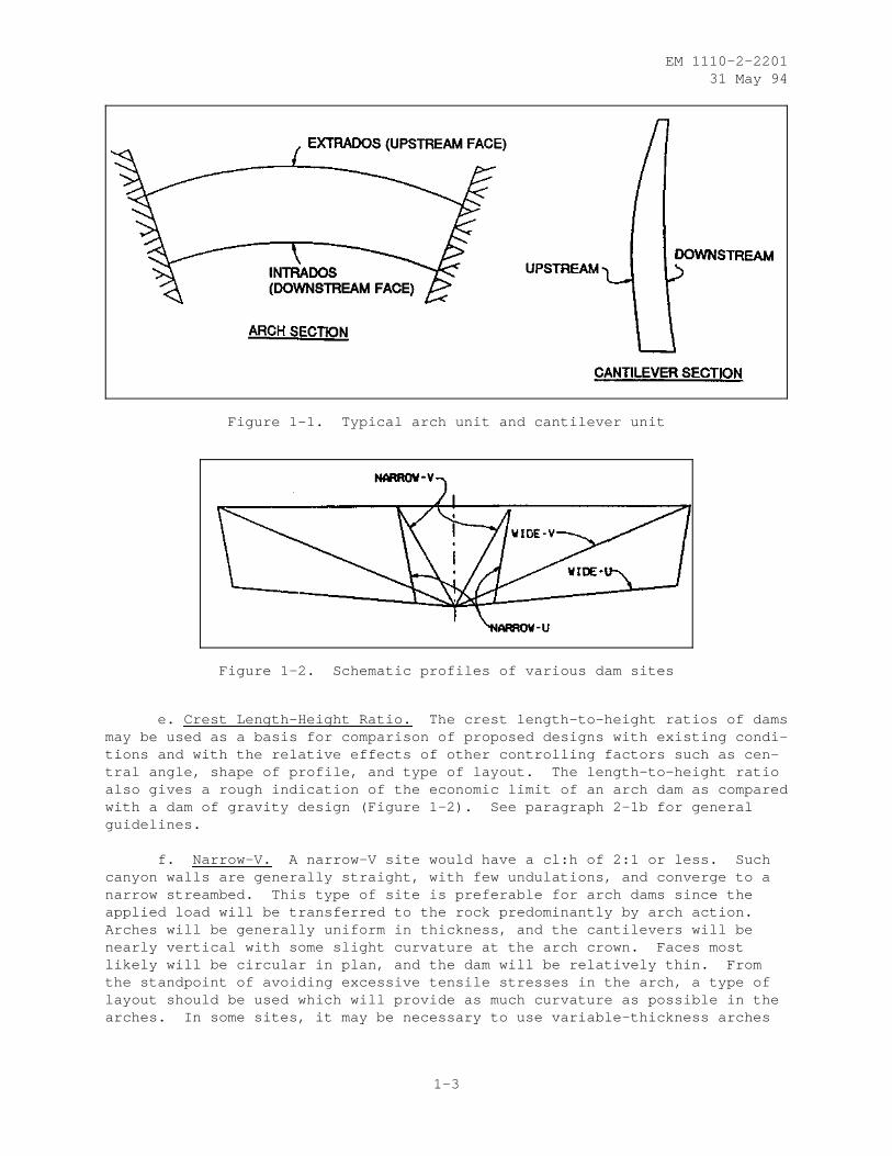
c. Extrados and Intrados. The terminology most commonly used inreferring to the upstream and downstream faces of an arch dam is extrados andintrados. Extrados is the upstream face of arches and intrados is the down-stream face of the arches. These terms are used only for the horizontal(arch) units; the faces of the cantilever units are referred to as upstreamand downstream, as appropriate. See Figure 1-1 for these definitions.
d. Site Shape. The overall shape of the site is classified as anarrow-V, wide-V, narrow-U, or wide-U as shown in Figure 1-2. These terms,while being subjective, present the designer a visualization of a site formfrom which to conceptually formulate the design. The terms also help thedesigner to develop knowledge and/or experience with dams at other sites.Common to all arch dam sites is the crest length-to-height ratio, cl:h.Assuming for comparison that factors such as central angle and height of damare equal, the arches of dams designed for wider canyons would be more flexi-ble in relation to cantilever stiffness than those of dams in narrow canyons,and a proportionately larger part of the load would be carried by cantileveraction.
1-2
EM 1110-2-220131 May 94
Figure 1-1. Typical arch unit and cantilever unit
Figure 1-2. Schematic profiles of various dam sites
e. Crest Length-Height Ratio. The crest length-to-height ratios of damsmay be used as a basis for comparison of proposed designs with existing condi-tions and with the relative effects of other controlling factors such as cen-tral angle, shape of profile, and type of layout. The length-to-height ratioalso gives a rough indication of the economic limit of an arch dam as comparedwith a dam of gravity design (Figure 1-2). See paragraph 2-1b for generalguidelines.
f. Narrow-V. A narrow-V site would have a cl:h of 2:1 or less. Suchcanyon walls are generally straight, with few undulations, and converge to anarrow streambed. This type of site is preferable for arch dams since theapplied load will be transferred to the rock predominantly by arch action.Arches will be generally uniform in thickness, and the cantilevers will benearly vertical with some slight curvature at the arch crown. Faces mostlikely will be circular in plan, and the dam will be relatively thin. Fromthe standpoint of avoiding excessive tensile stresses in the arch, a type oflayout should be used which will provide as much curvature as possible in thearches. In some sites, it may be necessary to use variable-thickness arches
1-3
EM 1110-2-220131 May 94
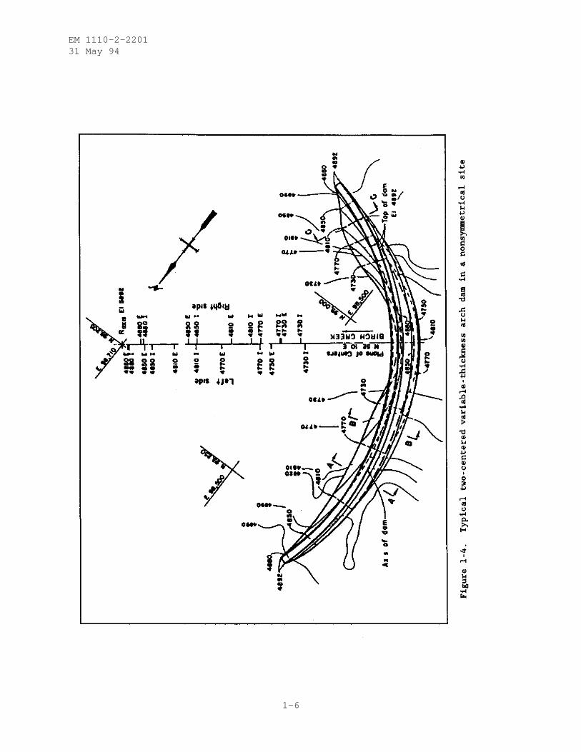
with a variation in location of circular arc centers to produce greater curva-ture in the lower arches. Figure 1-4 shows an example of a two-centered vari-able-thickness arch dam for a nonsymmetrical site.
g. Wide-V. A wide-V site would have a cl:h of 5:1 or more. The upperlimit for cl:h for arch dams is about 10:1. Canyon walls will have more pro-nounced undulations but will be generally straight after excavation, converg-ing to a less pronounced v-notch below the streambed. Most of the live loadwill be transferred to rock by arch action. Arches will generally be uniformin thickness with some possible increase in thickness near the abutments. The"crown" (central) cantilever will have more curvature and base thickness thanthat in a narrow-V of the same height. In plan, the crest most likely wouldbe three-centered and would transition to single-center circular arches at thestreambed. Arches would be thicker than those in the narrow-V site.
h. Narrow-U. In narrow-U sites, the canyon walls are near vertical inthe upper half of the canyon. The streambed width is fairly large, i.e., per-haps one-half the canyon width at the crest. Above 0.25h, most of the liveload will be transferred to rock by arch action. Below 0.25h, the live loadwill increasingly be supported by cantilever action toward the lowest point.There the cantilevers have become stubby while the arches are still relativelylong. The upper arches will be uniform in thickness but become variable inthickness near the streambed. The crown cantilever will have more curvaturethan the crown cantilever in a narrow-V site of equal height. Faces willgenerally be circular in plan. Arches will be thin because of the narrowsite. In dams constructed in U-shaped canyons, the lower arches have chordlengths almost as long as those near the top. In such cases, use of avariable-thickness arch layout will normally give a relatively uniform stressdistribution. Undercutting on the upstream face may be desirable to eliminateareas of tensile stress at the bases of cantilevers.
i. Wide-U. Wide-U sites are the most difficult for an arch dam designbecause most of the arches are long compared to the crest length. In thelower 0.25h, much of the live load is carried by cantilever action because thelong flexible arches carry relatively little load. In this area, cantileverthickness tends to increase rapidly to support the increased water pressure.Arch thickness variation in the horizontal direction may range from uniform atthe crest to variable at the streambed. The transition will most likely occurat about the upper one-third level. The crown cantilever here should have themost curvature of any type of site.
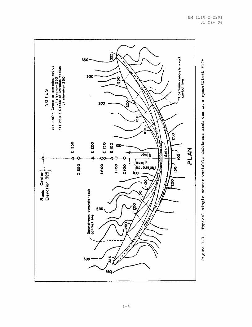
j. Reference Plane. As shown in Figures 1-3 through 1-5, the referenceplane is a vertical radial plane usually based in the streambed. The refer-ence plane contains the crown cantilever and the loci of the central centersas shown in Figure 1-6. It is from this plane that the angle to the archabutment is measured. Also shown are the axis and axis center. The axis is avertical surface curved in plan intersecting the crown cantilever at the crestand upstream face. The axis is developed in plan by the axis radius which isthe distance between the axis and the axis center located downstream. Amethod of estimating values for these terms will be described in a later sec-tion. The reference plane will theoretically consist of one, two, or threeplanes of centers. One plane of centers is used to describe arches in a sym-metrical site as shown in Figure 1-3. Two planes of centers are used todescribe arches in nonsymmetrical sites as shown in Figure 1-4. Three planes
1-4
EM 1110-2-220131 May 94
1-5
EM 1110-2-220131 May 94
1-6
EM 1110-2-220131 May 94
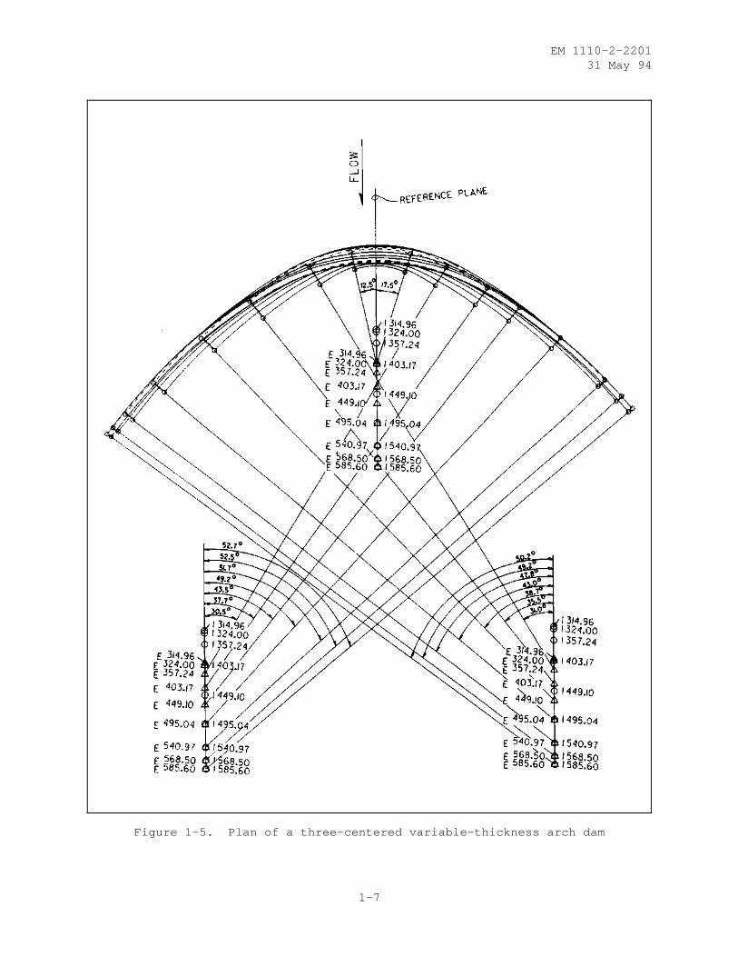
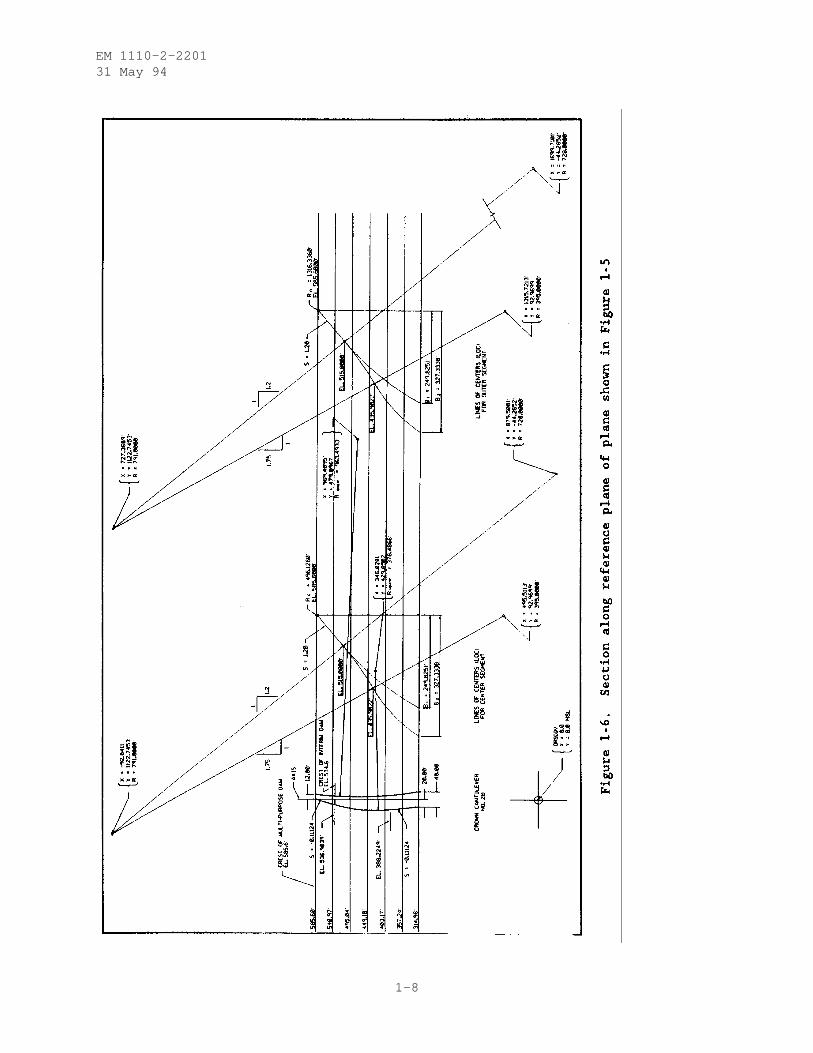
Figure 1-5. Plan of a three-centered variable-thickness arch dam
1-7
EM 1110-2-220131 May 94
1-8
EM 1110-2-220131 May 94
of centers are used to describe a three-centered arch dam as shown inFigure 1-5.
k. Crown Cantilever. The crown cantilever is defined as the maximumheight vertical cantilever and is usually located in the streambed. It isdirected radially toward the axis center. The crown cantilever and the archcrowns are at the same location on symmetrical arch dams. On nonsymmetricalarch dams, the arch crowns will be offset toward the longer side. Maximumradial deflections will occur at the crown cantilever of symmetrical dams butgenerally between the crown cantilever and arch crowns on nonsymmetrical archdams.
l. Single Curvature. Single-curvature arch dams are curved in planonly. Vertical sections, or cantilevers, have vertical or straight slopedfaces, or may also be curved with the limitation that no concrete overhangsthe concrete below. These types of shapes were common prior to 1950.
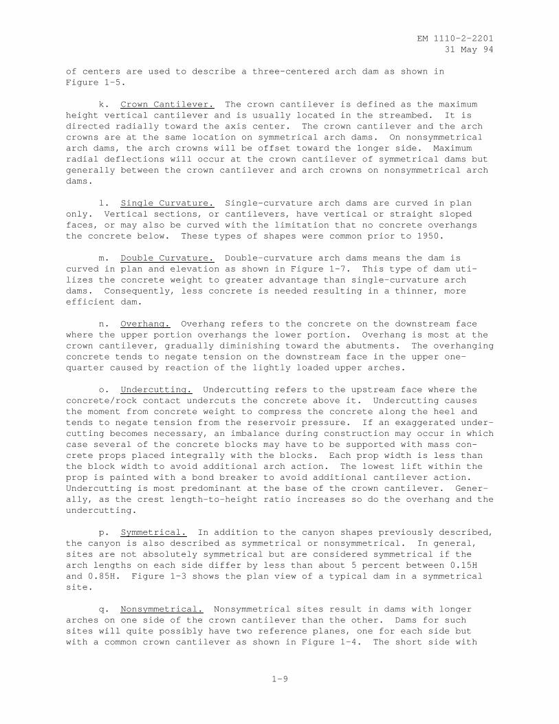
m. Double Curvature. Double-curvature arch dams means the dam iscurved in plan and elevation as shown in Figure 1-7. This type of dam uti-lizes the concrete weight to greater advantage than single-curvature archdams. Consequently, less concrete is needed resulting in a thinner, moreefficient dam.
n. Overhang. Overhang refers to the concrete on the downstream facewhere the upper portion overhangs the lower portion. Overhang is most at thecrown cantilever, gradually diminishing toward the abutments. The overhangingconcrete tends to negate tension on the downstream face in the upper one-quarter caused by reaction of the lightly loaded upper arches.
o. Undercutting. Undercutting refers to the upstream face where theconcrete/rock contact undercuts the concrete above it. Undercutting causesthe moment from concrete weight to compress the concrete along the heel andtends to negate tension from the reservoir pressure. If an exaggerated under-cutting becomes necessary, an imbalance during construction may occur in whichcase several of the concrete blocks may have to be supported with mass con-crete props placed integrally with the blocks. Each prop width is less thanthe block width to avoid additional arch action. The lowest lift within theprop is painted with a bond breaker to avoid additional cantilever action.Undercutting is most predominant at the base of the crown cantilever. Gener-ally, as the crest length-to-height ratio increases so do the overhang and theundercutting.
p. Symmetrical. In addition to the canyon shapes previously described,the canyon is also described as symmetrical or nonsymmetrical. In general,sites are not absolutely symmetrical but are considered symmetrical if thearch lengths on each side differ by less than about 5 percent between 0.15Hand 0.85H. Figure 1-3 shows the plan view of a typical dam in a symmetricalsite.
q. Nonsymmetrical. Nonsymmetrical sites result in dams with longerarches on one side of the crown cantilever than the other. Dams for suchsites will quite possibly have two reference planes, one for each side butwith a common crown cantilever as shown in Figure 1-4. The short side with
1-9
EM 1110-2-220131 May 94
Figure 1-7. Example of single- and double-curvature dams
the steeper-wall canyon will have shorter radii and exhibit more arch action.Whereas the longer side, abutting into the flatter slope, will have less archaction and will be relatively thicker along the abutments. In general, themaximum deflection at each elevation will not occur at the crown cantileverbut more toward the midpoint of each arch. A different axis radius for eachside will be necessary. To maintain continuity, however, each pair of linesmust lie along the reference plane. In some cases the axis radius (R axis ) maybe different on each side, and the arches may be uniform or variable in thick-ness. A region of stress concentration is likely to exist in an arch damhaving a nonsymmetrical profile. In some cases improvements of a nonsymmetri-cal layout by one or a combination of the following methods may be warranted:by excavating deeper in appropriate places, by constructing an artificialabutment, or by reorienting and/or relocating the dam.
r. Lines of Centers. A line in space which is the loci of centers forcircular arcs is used to describe a face of the dam. For uniform-thicknessarches, a single line of centers will describe the extrados and intradosfaces. Variable-thickness arches require two lines of centers. Nonsym-metrical sites need one or two lines of centers for each side of the dam.Three-centered arches have three lines of centers as shown in Figure 1-6. Itshould be noted in Figure 1-6 that the lines of centers for the outer segmentsare identical and only one pair is shown. Also, in Figure 1-6, arches ofvariable thickness are used below elevation 515 feet.
s. Constant Center. A constant-center dam has a vertical line at theaxis center to describe the center for all arches. All arches are uniform inthickness and the crown cantilever is representative of all vertical sections.
1-10
EM 1110-2-220131 May 94
t. Single Center. Single-center constant thickness arches have thesame center describing the extrados and the intrados which means all archesare uniform in thickness between abutments. Single-center variable-thicknessarches have different centers describing the extrados and the intrados; how-ever, both lie along the reference plane. The lines of centers need not bevertical but must be coplanar with the crown cantilever. This arch shape isapplicable to narrow canyon sites such as those with cl:h less than 3:1.
u. Two Centered. In two-centered arches, both planes are coplanar withthe crown cantilever. The left plane contains the extrados and intrados linesof centers required to properly shape the left side of the arches as measuredfrom the crown cantilever to the abutments. The right plane of centers con-tains the extrados and intrados lines of centers for the right-side arches.
v. Three Centered. With three-centered arches, only the center segmentis coplanar with the crown cantilever. The center segment and outer segmentare coplanar at an angle of compound curvature as measured from the referenceplane. Three-centered arches approximate an ellipse. Figure 1-5 shows atypical three-centered arch. A parabola can be approximated by using straighttangents in the outer segment instead of arcs. Three-centered or ellipticalarches can be used advantageously in wide-U or V-shaped canyons. Ellipticalarches have the inherent characteristics of conforming more nearly to the lineof thrust for wide sites than do circular arches. Consequently, the concreteis stressed more uniformly throughout its thickness. Because of the smallerinfluences from moments, elliptical arches require little, if any, variablethickness.
1-11
EM 1110-2-220131 May 94
CHAPTER 2
GENERAL DESIGN CONSIDERATIONS
2-1. Dam Site. Unlike a concrete gravity dam which carries the entire loadby its self weight, an arch dam obtains its stability by both the self weightand, to a great extent, by transmitting the imposed loads by arch action intothe valley walls. The geometry of the dam site is, therefore, the most basicconsideration in the selection of an arch dam. As a general rule, an arch damrequires a site with abutments of sufficient strength to support the archthrust. On special occasions artificial abutments - thrust blocks - may beused in the absence of suitable abutment(s); see Chapter 3 for additionaldiscussion on thrust blocks.
2-2. Length-Height Ratio. Traditionally, most of the arch dams in theUnited States have been constructed in canyon sites with length-height ratiosof less than 4 to 1. Although the greatest economic advantage may be realizedfor a length-height ratio of less than 4 to 1, sites with greater ratiosshould also be given serious consideration. With the present state of the artin arch dam design automation, it is now possible to obtain "optimum design"for sites which would have been considered difficult in the past. An arch dammust be given first consideration for a site with length-height ratio of 3 orless. For sites having length-height ratios between 3 and 6, an arch dam maystill provide the most feasible structure depending on the extent of founda-tion excavation required to reach suitable material. The effect of factorsother than length-height ratio becomes much more predominant in the selectionprocess for dam sites with length-height ratios greater than 6. For thesesites a careful study must be performed with consideration given to the diver-sion requirements, availability of construction material, and spillway andoutlet works requirements. The results of these studies may prove the archdam as a viable choice for wider sites.
2-3. Smooth Abutments. The arch dam profile should be made as smooth aspracticable. The overall appearance on each abutment should resemble a smoothgeometric curve composed of one or two parabolas or hyperbolas. One point ofcontraflexure in the profile of each abutment will provide for a smooth forcedistribution along the rock contact. Each original ground surface may have avery irregular profile before excavation, but the prominent points should beremoved together with removing weathering to sound rock. Each abutment sur-face irregularity of peaks and valleys represents points of force concentra-tion at the peaks and correspondingly less force in the valleys. As can bereadily surmised, design difficulties lead to structural inefficiencies, moreconcrete, and increased costs. Thus, it is generally prudent engineering fromthe beginning to overexcavate the rock and provide for a smooth profile. Atthe microscale, the abutment should be made smooth, that is, rock knobsremaining after the macroexcavation should, after consensus with thegeologist, be removed. Generally, the excavation lines shown in the specifi-cations have tolerances such a s ± 1 foot in 20 feet.
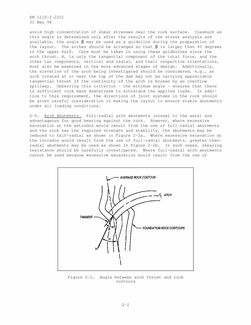
2-4. Angle Between Arch and Abutment. Given a geometrically suitable site,another important consideration of an arch dam is the rock contour lines, orthe angle which the arches make with the abutment rock contour lines. Theangle α in Figure 2-1 should, as a general rule, be greater than 30 degrees to
2-1
EM 1110-2-220131 May 94
avoid high concentration of shear stresses near the rock surface. Inasmuch asthis angle is determined only after the results of the stress analysis areavailable, the angle β may be used as a guideline during the preparation ofthe layout. The arches should be arranged so that β is larger than 40 degreesin the upper half. Care must be taken in using these guidelines since thearch thrust, H, is only the tangential component of the total force, and theother two components, vertical and radial, and their respective orientations,must also be examined in the more advanced stages of design. Additionally,the elevation of the arch being investigated should be considered, e.g., anarch located at or near the top of the dam may not be carrying appreciabletangential thrust if the continuity of the arch is broken by an overflowspillway. Observing this criterion - the minimum angle - ensures that thereis sufficient rock mass downstream to withstand the applied loads. In addi-tion to this requirement, the directions of joint systems in the rock shouldbe given careful consideration in making the layout to ensure stable abutmentsunder all loading conditions.
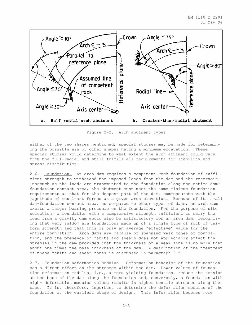
2-5. Arch Abutments. Full-radial arch abutments (normal to the axis) areadvantageous for good bearing against the rock. However, where excessiveexcavation at the extrados would result from the use of full-radial abutmentsand the rock has the required strength and stability, the abutments may bereduced to half-radial as shown in Figure 2-2a. Where excessive excavation atthe intrados would result from the use of full-radial abutments, greater-than-radial abutments may be used as shown in Figure 2-2b. In such cases, shearingresistance should be carefully investigated. Where full-radial arch abutmentscannot be used because excessive excavation would result from the use of
Figure 2-1. Angle between arch thrust and rockcontours
2-2
EM 1110-2-220131 May 94
Figure 2-2. Arch abutment types
either of the two shapes mentioned, special studies may be made for determin-ing the possible use of other shapes having a minimum excavation. Thesespecial studies would determine to what extent the arch abutment could varyfrom the full-radial and still fulfill all requirements for stability andstress distribution.
2-6. Foundation. An arch dam requires a competent rock foundation of suffi-cient strength to withstand the imposed loads from the dam and the reservoir.Inasmuch as the loads are transmitted to the foundation along the entire dam-foundation contact area, the abutment must meet the same minimum foundationrequirements as that for the deepest part of the dam, commensurate with themagnitude of resultant forces at a given arch elevation. Because of its smalldam-foundation contact area, as compared to other types of dams, an arch damexerts a larger bearing pressure on the foundation. For the purpose of siteselection, a foundation with a compressive strength sufficient to carry theload from a gravity dam would also be satisfactory for an arch dam, recogniz-ing that very seldom are foundations made up of a single type of rock of uni-form strength and that this is only an average "effective" value for theentire foundation. Arch dams are capable of spanning weak zones of founda-tion, and the presence of faults and shears does not appreciably affect thestresses in the dam provided that the thickness of a weak zone is no more thanabout one times the base thickness of the dam. A description of the treatmentof these faults and shear zones is discussed in paragraph 3-5.
2-7. Foundation Deformation Modulus. Deformation behavior of the foundationhas a direct effect on the stresses within the dam. Lower values of founda-tion deformation modulus, i.e., a more yielding foundation, reduce the tensionat the base of the dam along the foundation and, conversely, a foundation withhigh- deformation modulus values results in higher tensile stresses along thebase. It is, therefore, important to determine the deformation modulus of thefoundation at the earliest stage of design. This information becomes more
2-3
EM 1110-2-220131 May 94
critical when there are indications that the deformation modulus for one abut-ment may be drastically different than for the other abutment. Having thisknowledge at early stages of design, the structural designer can shape the damproperly so that excessive stresses are avoided. A foundation should not beconsidered inadequate solely because of low values of deformation moduli.Foundation grouting may improve the deformation behavior of the rock mass andshould be considered in determining the deformation moduli used in the designof the dam. When deformation values smaller than 500,000 pounds per squareinch (psi) are present, the question of how much a grouting program canimprove the foundation becomes critical, and a thorough stress analysis shouldbe performed using a reasonable range of deformation moduli. The design isacceptable if the dam stresses are within allowable stresses under all assumedconditions.
2-8. Effect of Overflow Spillway. If an overflow type of spillway is usedand is located near the center of the dam, no arch action is considered abovethe crest elevation of the spillway. If a spillway is located near one sideof the dam, there may be some arch action above the crest elevation of thespillway. In either case, the upper portion of the dam above the spillwaycrest must be designed to withstand the effects of the loading imposed abovethe crest by water pressure, concrete mass, temperature, and earthquake.
2-4
EM 1110-2-220131 May 94
CHAPTER 3
SPILLWAYS, OUTLET WORKS AND APPURTENANCES,AND RESTITUTION CONCRETE
3-1. Introduction. This chapter describes the influence of voids through thearch dam and structural additions outside the theoretical limits of the archdam. Voids through the dam in the radial direction are spillways, accessadits, and outlet works, in the tangential direction are adits, galleries, andtunnels, and in the vertical direction are stairway wells and elevator shafts.Often associated with spillways and outlet works are blockouts or chambers forgate structures. External structures are restitution concrete which includesthrust blocks, pads, pulvino, socle, or other dental type concrete, spillwayflip buckets on the downstream face, and corbels on the upstream face.
3-2. Spillways. Numerous types of spillways are associated with arch dams.Each is a function of the project purpose, i.e., storage or detention, or tobypass flood flows or flows that exceed diversion needs. Spillways for con-crete dams may be considered attached or detached.
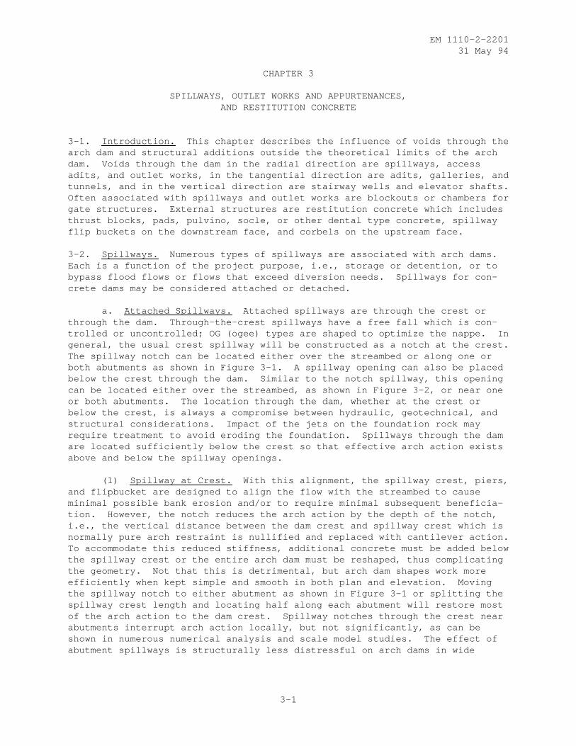
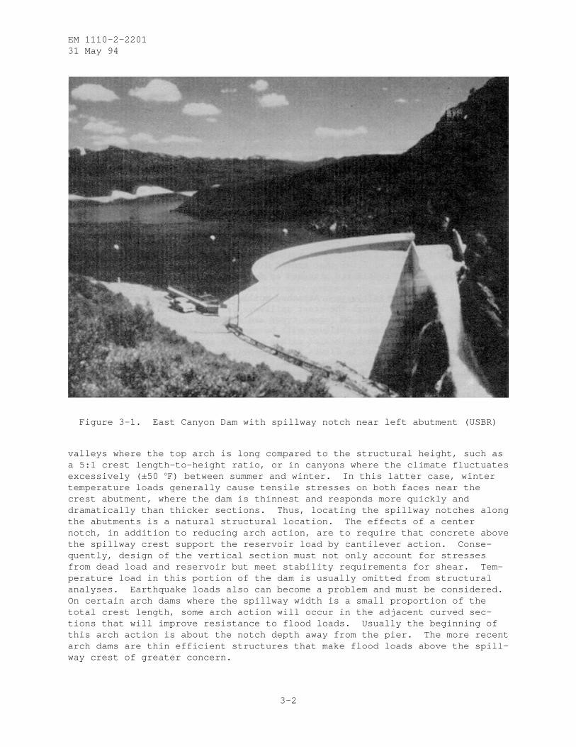
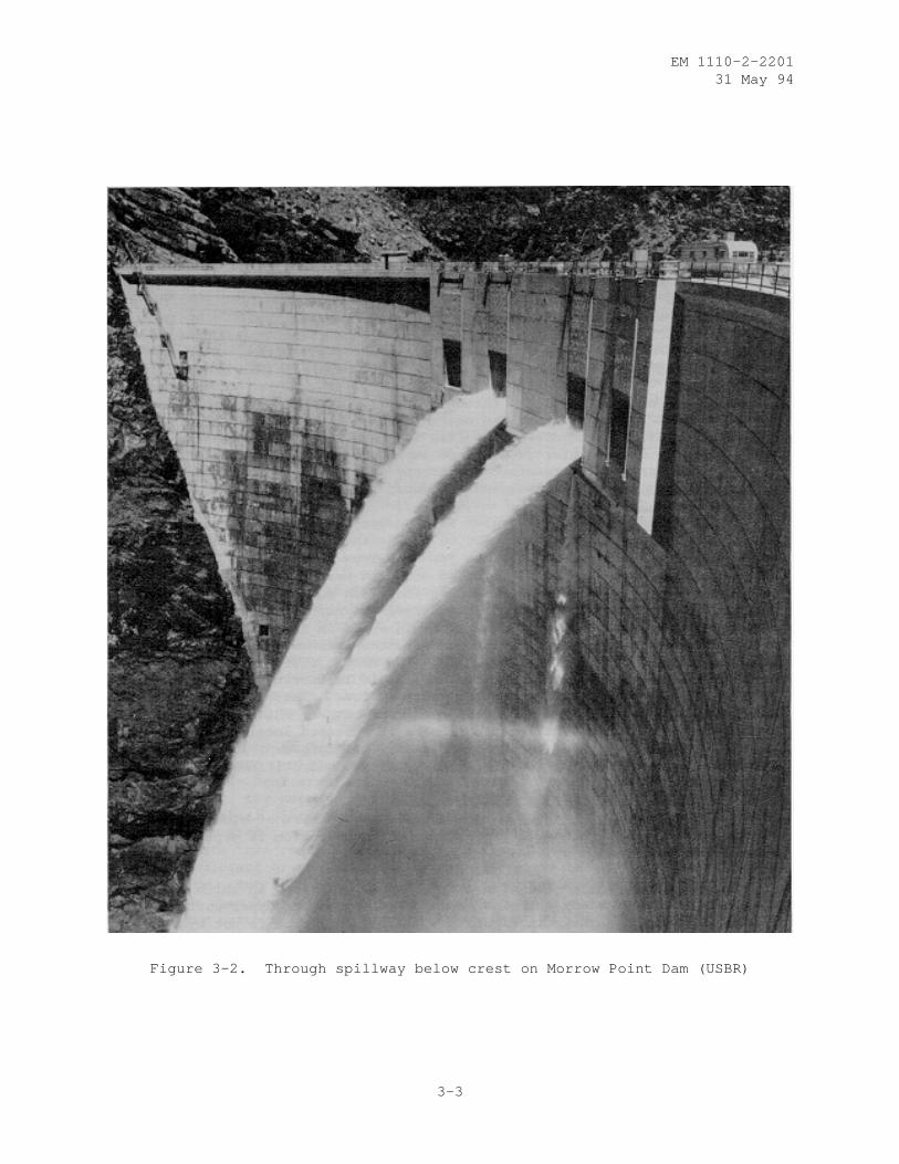
a. Attached Spillways. Attached spillways are through the crest orthrough the dam. Through-the-crest spillways have a free fall which is con-trolled or uncontrolled; OG (ogee) types are shaped to optimize the nappe. Ingeneral, the usual crest spillway will be constructed as a notch at the crest.The spillway notch can be located either over the streambed or along one orboth abutments as shown in Figure 3-1. A spillway opening can also be placedbelow the crest through the dam. Similar to the notch spillway, this openingcan be located either over the streambed, as shown in Figure 3-2, or near oneor both abutments. The location through the dam, whether at the crest orbelow the crest, is always a compromise between hydraulic, geotechnical, andstructural considerations. Impact of the jets on the foundation rock mayrequire treatment to avoid eroding the foundation. Spillways through the damare located sufficiently below the crest so that effective arch action existsabove and below the spillway openings.
(1) Spillway at Crest. With this alignment, the spillway crest, piers,and flipbucket are designed to align the flow with the streambed to causeminimal possible bank erosion and/or to require minimal subsequent beneficia-tion. However, the notch reduces the arch action by the depth of the notch,i.e., the vertical distance between the dam crest and spillway crest which isnormally pure arch restraint is nullified and replaced with cantilever action.To accommodate this reduced stiffness, additional concrete must be added belowthe spillway crest or the entire arch dam must be reshaped, thus complicatingthe geometry. Not that this is detrimental, but arch dam shapes work moreefficiently when kept simple and smooth in both plan and elevation. Movingthe spillway notch to either abutment as shown in Figure 3-1 or splitting thespillway crest length and locating half along each abutment will restore mostof the arch action to the dam crest. Spillway notches through the crest nearabutments interrupt arch action locally, but not significantly, as can beshown in numerous numerical analysis and scale model studies. The effect ofabutment spillways is structurally less distressful on arch dams in wide
3-1
EM 1110-2-220131 May 94
Figure 3-1. East Canyon Dam with spillway notch near left abutment (USBR)
valleys where the top arch is long compared to the structural height, such asa 5:1 crest length-to-height ratio, or in canyons where the climate fluctuatesexcessively (±50 oF) between summer and winter. In this latter case, wintertemperature loads generally cause tensile stresses on both faces near thecrest abutment, where the dam is thinnest and responds more quickly anddramatically than thicker sections. Thus, locating the spillway notches alongthe abutments is a natural structural location. The effects of a centernotch, in addition to reducing arch action, are to require that concrete abovethe spillway crest support the reservoir load by cantilever action. Conse-quently, design of the vertical section must not only account for stressesfrom dead load and reservoir but meet stability requirements for shear. Tem-perature load in this portion of the dam is usually omitted from structuralanalyses. Earthquake loads also can become a problem and must be considered.On certain arch dams where the spillway width is a small proportion of thetotal crest length, some arch action will occur in the adjacent curved sec-tions that will improve resistance to flood loads. Usually the beginning ofthis arch action is about the notch depth away from the pier. The more recentarch dams are thin efficient structures that make flood loads above the spill-way crest of greater concern.
3-2
EM 1110-2-220131 May 94
Figure 3-2. Through spillway below crest on Morrow Point Dam (USBR)
3-3
EM 1110-2-220131 May 94
(2) Spillways Below Crest (thru Spillways). Spillways are constructedthrough the arch dam at some optimal distance below the dam crest to reducethe plunge and provide for additional discharge. The spillway may be visual-ized as multiple orifices, either round or rectangular, and controlled withsome type of gates. The set of openings either may be centered over thestreambed as shown in Figure 3-2 or split toward either or both abutments.The set is surrounded by mass concrete and locally reinforced to preserve, forthe analyses, the assumption of a homogenous and monolithic structure. Withthis in mind, local reinforcement and/or added mass concrete must be designedso that the dam as a whole is not affected by the existence of the spillway.To minimize disruption of the flow of forces within the dam, the several open-ings should be aligned with the major principal compressive stresses resultingfrom the most frequent loading combination. Around the abutment, the majorprincipal stresses on the downstream face are generally normal to the abut-ment. This alignment would tend to stagger the openings, thus creating designdifficulties. In practice, however, all openings are aligned at the sameelevation and oriented radially through the dam. If necessary, each orificemay be directed at a predetermined nonradial angle to converge the flows forenergy dissipation or to direct the flow to a smaller impact area such as astilling basin or a reinforced concrete impact pad. Between each orifice,within a set, are normal reinforced concrete piers designed to support thegravity load above the spillway and the water force on the gates.
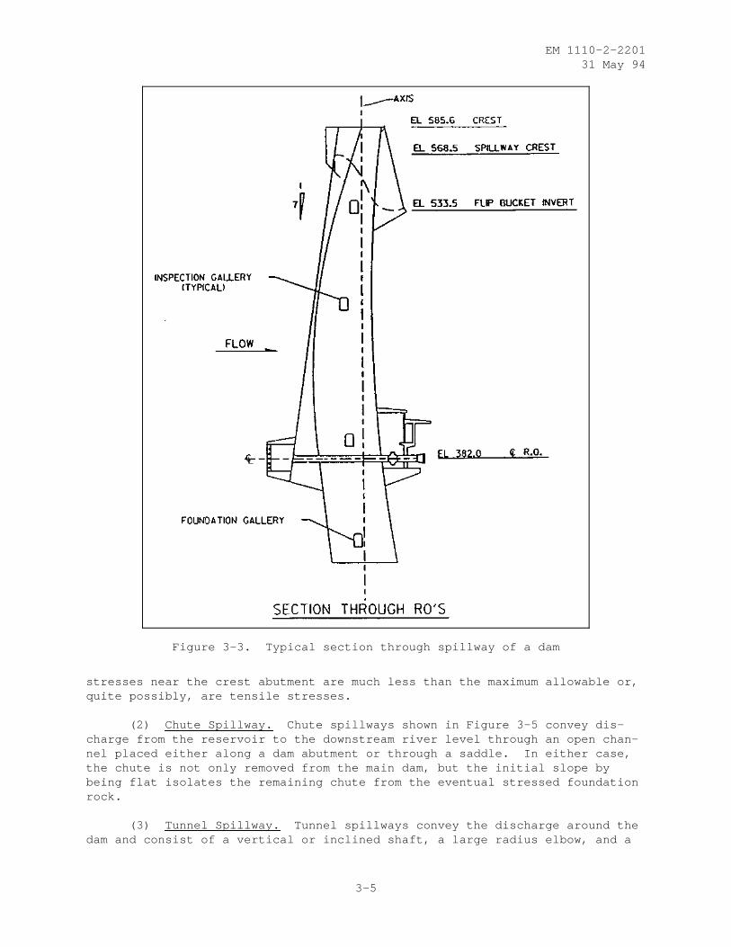
(3) Flip Bucket. The massive flip bucket, depending on site condi-tions, may be located near the crest to direct the jet impact near the dam toeor farther down the face to flip the jet away from the toe. In either case,the supporting structure is constructed of solid mass concrete generally withvertical sides. By judiciously limiting its width and height, the supportingstructure may be designed not to add stiffness to any of the arches or canti-levers. To assure this result, mastic is inserted in the contraction jointsto the theoretical limits of the downstream face defined before the flipbucket was added as shown in Figure 3-3. The mastic disrupts any arch actionthat might develop. For the same reason, mastic is inserted during construc-tion in the OG corbel overhang on the upstream face. These features protectthe smooth flow of stresses and avoid reentrant corners which may precipitatecracking or spalling. Cantilever stiffness is enhanced locally but not enoughto cause redistribution of the applied loads. Reinforcement in the supportingstructure and accompanying training walls will not add stiffness to the archdam.
b. Detached Spillways. Detached spillways consist of side channel,chute, tunnel, and morning glory spillways. The selection is dependent uponsite conditions.
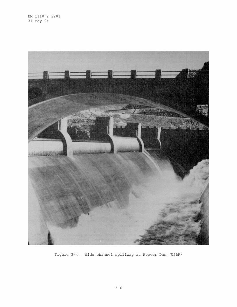
(1) Side Channel. The side channel spillway is one in which the con-trol weir is placed along the side of and parallel to the upper portion of thedischarge channel as shown in Figure 3-4. While this type is not hydrauli-cally efficient nor inexpensive, it is used where a long overflow crest isdesired to limit the surcharge head, where the abutments are steep, or wherethe control must be connected to a narrow channel or tunnel. Consequently, bybeing entirely upstream from the arch dam, the spillway causes no interferencewith the dam and only has a limited effect on the foundation. Similarly,along the upstream abutment, any spillway interference is mitigated by theusual low stresses in the foundation caused by the dam loads. Usually,
3-4
EM 1110-2-220131 May 94
Figure 3-3. Typical section through spillway of a dam
stresses near the crest abutment are much less than the maximum allowable or,quite possibly, are tensile stresses.
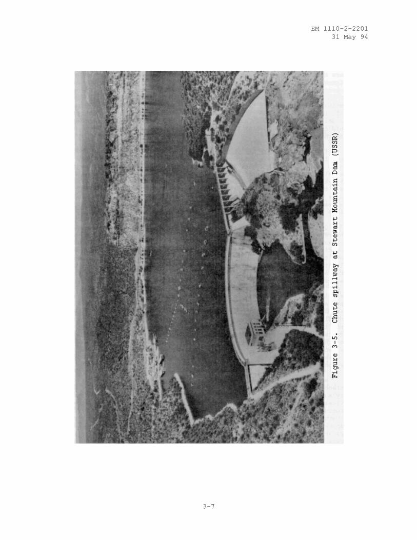
(2) Chute Spillway. Chute spillways shown in Figure 3-5 convey dis-charge from the reservoir to the downstream river level through an open chan-nel placed either along a dam abutment or through a saddle. In either case,the chute is not only removed from the main dam, but the initial slope bybeing flat isolates the remaining chute from the eventual stressed foundationrock.
(3) Tunnel Spillway. Tunnel spillways convey the discharge around thedam and consist of a vertical or inclined shaft, a large radius elbow, and a
3-5
EM 1110-2-220131 May 94
Figure 3-4. Side channel spillway at Hoover Dam (USBR)
3-6
EM 1110-2-220131 May 94
3-7
EM 1110-2-220131 May 94
horizontal tunnel at the downstream end. Tunnel spillways may presentadvantages for damsites in narrow canyons with steep abutments or at siteswhere there is danger to open channels from snow or rock slides. The tunnelalignment usually traverses the stressed foundation and consequently should beat least one abutment thickness from the concrete to rock contact. Any needfor increased spacing would be based on structural height and applied loadcombinations. Note that these tunnels are designed to flow up to 75 percentfull, in which case in situ and superimposed stresses from the dam may governthe design. The corollary is that the tunnel walls must be strong enough toavoid creating a weakness in the foundation and subsequent stability problemswith the dam.
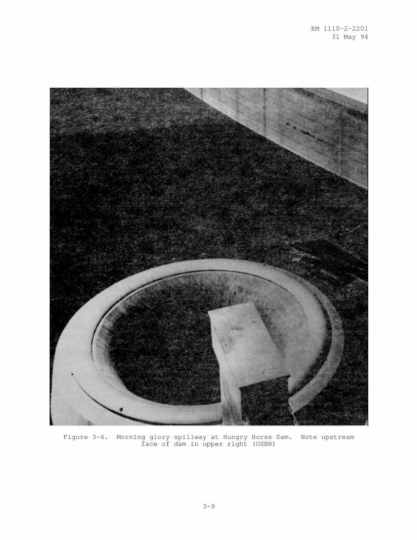
(4) Morning Glory Spillway. A morning glory spillway such as thatshown in Figure 3-6 is one in which the water enters over a horizontally posi-tioned lip, which is circular in plan, and then flows to the downstream riverchannel through a horizontal or near horizontal tunnel. A morning gloryspillway usually can be used advantageously at damsites in narrow canyonswhere the abutments rise steeply or where a diversion tunnel is available foruse as the downstream leg. If a vertical drop structure is to be locatedupstream, it should not interfere structurally with the dam. A sloping tunneloffers the same concerns as previously discussed.
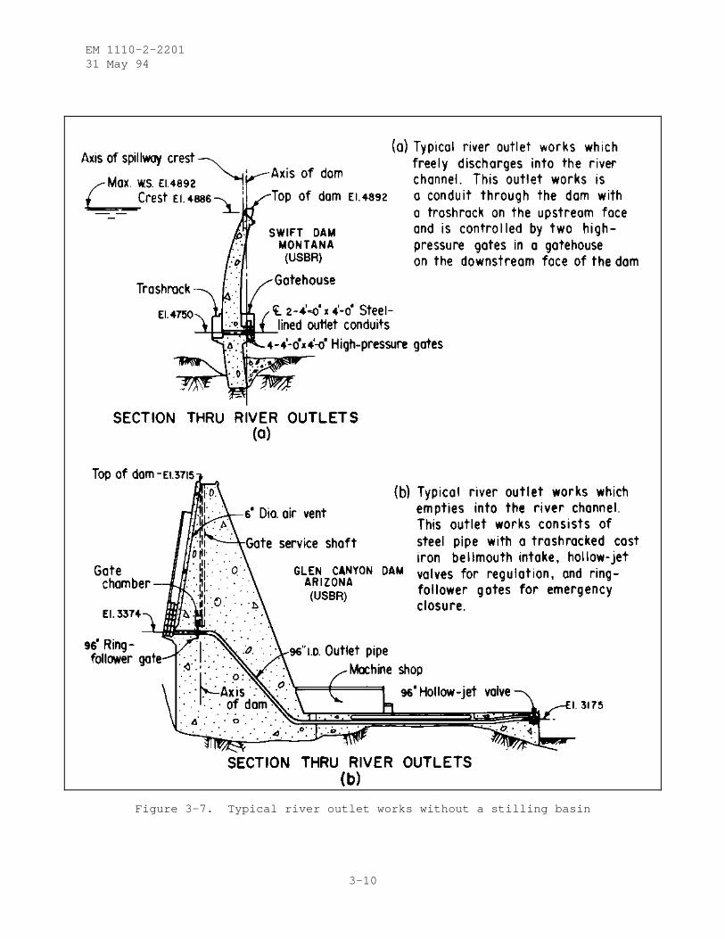
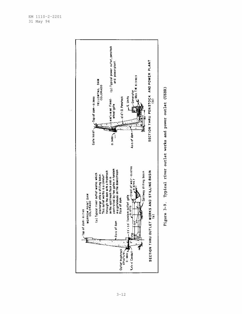
3-3. Outlet Works. Outlet works are a combination of structures and equip-ment required for the safe operation and control of water released from areservoir to serve downstream needs. Outlet works are usually classifiedaccording to their purpose such as river outlets, which serve to regulateflows to the river and control the reservoir elevation, irrigation or munici-pal water supply outlets, which control the flow of water into a canal, pipe-line, or river to satisfy specified needs, or, power outlets, which providepassage of water to turbines for power generation. In general, outlet worksdo not structurally impact the design of an arch dam as shown in Figure 3-7.The major difficulty may lie in adapting the outlet works to the arch dam,especially a small double-curvature thin arch dam where the midheight thick-ness may be 25 feet or less. Taller and/or heavier dams will have a signifi-cant differential head between the intake and the valve or gate house, and theconduit may have several bends. All of the features can be designed and con-structed but not without some compromise. Outlet works should be located awayfrom the abutments to avoid interference with the smooth flow of stresses intothe rock and smooth flow of water into the conduit. A nominal distance of10 diameters will provide sufficient space for convergence of stresses pastthe conduit.
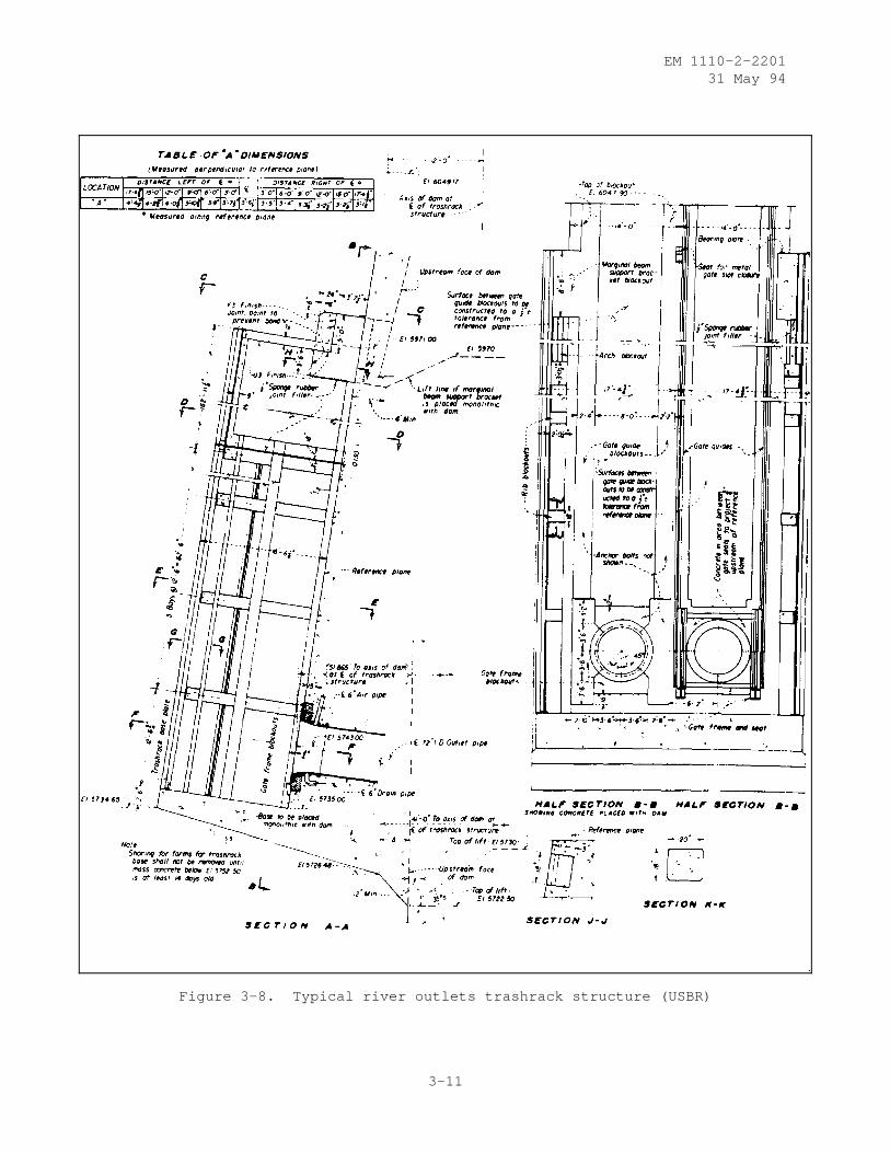
a. Intake Structures. Intake structures, in addition to forming theentrance into the outlet works, may accommodate control devices and the neces-sary auxiliary appurtenances such as trashracks, fish screens, and bypassdevices (Figure 3-8). An intake structure usually consists of a submergedstructure on the upstream face or an intake tower in the reservoir. Verticalcurvature on the upstream face may result in more than usual massive concretecomponents as shown in Figure 3-9 to provide a straight track for the stoplogs or bulkhead gate. A compromise to relieve some of the massiveness is torecess portions of the track into the dam face. This recess which resembles arectangular notch in plan reduces the stiffness of those arches involved notonly at the notch but for some lateral distance, depending on the notch depth.
3-8
EM 1110-2-220131 May 94
Figure 3-6. Morning glory spillway at Hungry Horse Dam. Note upstreamface of dam in upper right (USBR)
3-9
EM 1110-2-220131 May 94
Figure 3-7. Typical river outlet works without a stilling basin
3-10
EM 1110-2-220131 May 94
Figure 3-8. Typical river outlets trashrack structure (USBR)
3-11
EM 1110-2-220131 May 94
3-12
EM 1110-2-220131 May 94
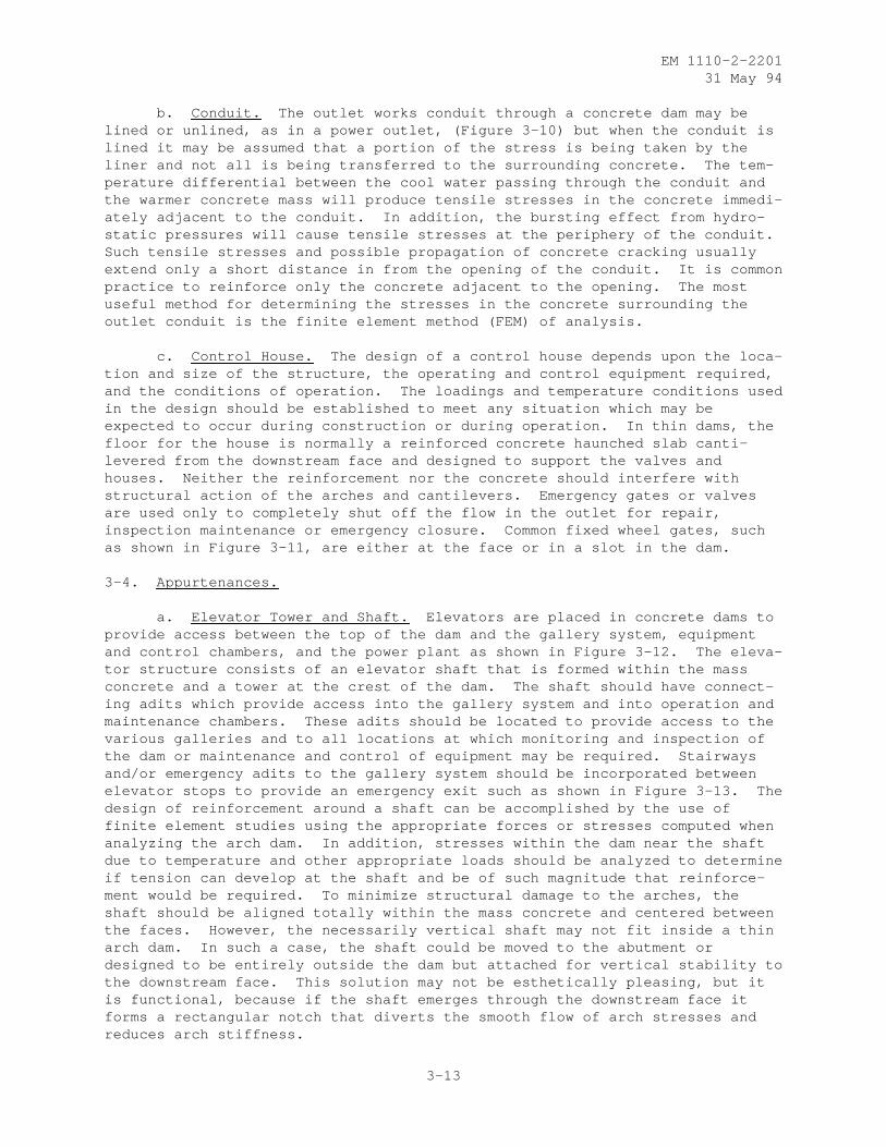
b. Conduit. The outlet works conduit through a concrete dam may belined or unlined, as in a power outlet, (Figure 3-10) but when the conduit islined it may be assumed that a portion of the stress is being taken by theliner and not all is being transferred to the surrounding concrete. The tem-perature differential between the cool water passing through the conduit andthe warmer concrete mass will produce tensile stresses in the concrete immedi-ately adjacent to the conduit. In addition, the bursting effect from hydro-static pressures will cause tensile stresses at the periphery of the conduit.Such tensile stresses and possible propagation of concrete cracking usuallyextend only a short distance in from the opening of the conduit. It is commonpractice to reinforce only the concrete adjacent to the opening. The mostuseful method for determining the stresses in the concrete surrounding theoutlet conduit is the finite element method (FEM) of analysis.
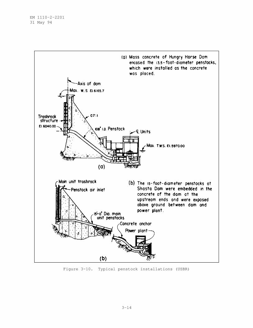
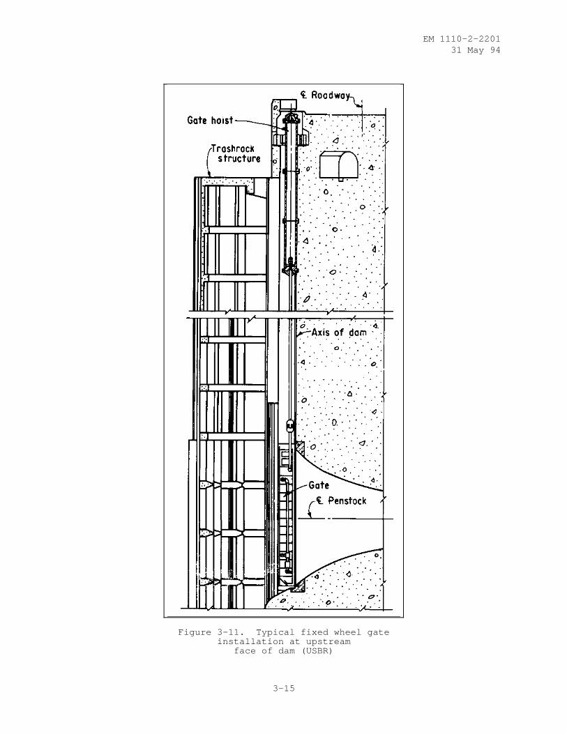
c. Control House. The design of a control house depends upon the loca-tion and size of the structure, the operating and control equipment required,and the conditions of operation. The loadings and temperature conditions usedin the design should be established to meet any situation which may beexpected to occur during construction or during operation. In thin dams, thefloor for the house is normally a reinforced concrete haunched slab canti-levered from the downstream face and designed to support the valves andhouses. Neither the reinforcement nor the concrete should interfere withstructural action of the arches and cantilevers. Emergency gates or valvesare used only to completely shut off the flow in the outlet for repair,inspection maintenance or emergency closure. Common fixed wheel gates, suchas shown in Figure 3-11, are either at the face or in a slot in the dam.
3-4. Appurtenances.
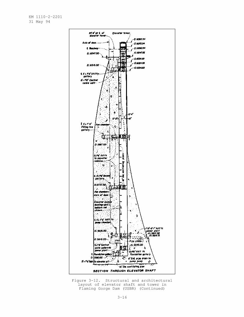
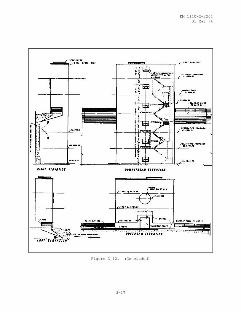
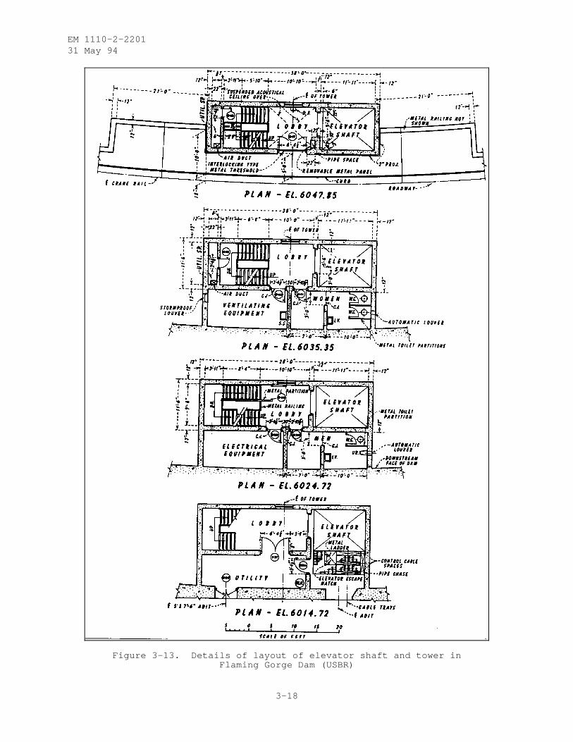
a. Elevator Tower and Shaft. Elevators are placed in concrete dams toprovide access between the top of the dam and the gallery system, equipmentand control chambers, and the power plant as shown in Figure 3-12. The eleva-tor structure consists of an elevator shaft that is formed within the massconcrete and a tower at the crest of the dam. The shaft should have connect-ing adits which provide access into the gallery system and into operation andmaintenance chambers. These adits should be located to provide access to thevarious galleries and to all locations at which monitoring and inspection ofthe dam or maintenance and control of equipment may be required. Stairwaysand/or emergency adits to the gallery system should be incorporated betweenelevator stops to provide an emergency exit such as shown in Figure 3-13. Thedesign of reinforcement around a shaft can be accomplished by the use offinite element studies using the appropriate forces or stresses computed whenanalyzing the arch dam. In addition, stresses within the dam near the shaftdue to temperature and other appropriate loads should be analyzed to determineif tension can develop at the shaft and be of such magnitude that reinforce-ment would be required. To minimize structural damage to the arches, theshaft should be aligned totally within the mass concrete and centered betweenthe faces. However, the necessarily vertical shaft may not fit inside a thinarch dam. In such a case, the shaft could be moved to the abutment ordesigned to be entirely outside the dam but attached for vertical stability tothe downstream face. This solution may not be esthetically pleasing, but itis functional, because if the shaft emerges through the downstream face itforms a rectangular notch that diverts the smooth flow of arch stresses andreduces arch stiffness.
3-13
EM 1110-2-220131 May 94
Figure 3-10. Typical penstock installations (USBR)
3-14
EM 1110-2-220131 May 94
Figure 3-11. Typical fixed wheel gateinstallation at upstream
face of dam (USBR)
3-15
EM 1110-2-220131 May 94
Figure 3-12. Structural and architecturallayout of elevator shaft and tower inFlaming Gorge Dam (USBR) (Continued)
3-16
EM 1110-2-220131 May 94
Figure 3-12. (Concluded)
3-17
EM 1110-2-220131 May 94
Figure 3-13. Details of layout of elevator shaft and tower inFlaming Gorge Dam (USBR)
3-18
EM 1110-2-220131 May 94
b. Bridges. Bridges may be required on the top of the dam to carry ahighway over the spillway or to provide roadway access to the top of the damat some point other than its end. Design criteria for highway bridges usuallyconform to the standard specifications adopted by the American Association ofState Highway Officials and are modified to satisfy local conditions and anyparticular requirement of the project. Bridges, regardless of how heavy,whether of steel or concrete, or with fixed or pinned connections, are notconsidered sufficiently strong to transfer arch loads from one mass concretepier to the other.
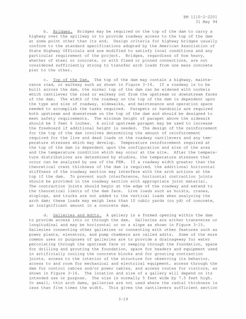
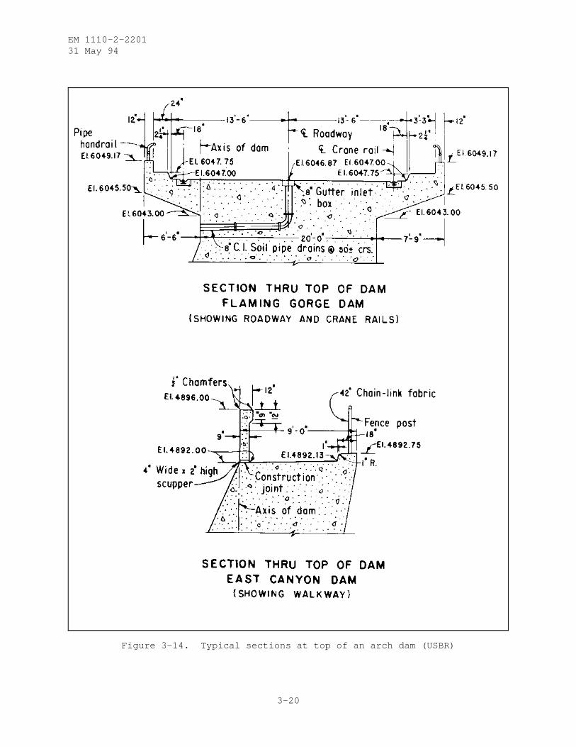
c. Top of the Dam. The top of the dam may contain a highway, mainte-nance road, or walkway such as shown in Figure 3-14. If a roadway is to bebuilt across the dam, the normal top of the dam can be widened with corbelswhich cantilever the road or walkway out from the upstream or downstream facesof the dam. The width of the roadway on the top of the dam is dependent uponthe type and size of roadway, sidewalks, and maintenance and operation spaceneeded to accomplish the tasks required. Parapets or handrails are requiredboth upstream and downstream on the top of the dam and should be designed tomeet safety requirements. The minimum height of parapet above the sidewalkshould be 3 feet 6 inches. A solid upstream parapet may be used to increasethe freeboard if additional height is needed. The design of the reinforcementfor the top of the dam involves determining the amount of reinforcementrequired for the live and dead loads on the roadway cantilevers and any tem-perature stresses which may develop. Temperature reinforcement required atthe top of the dam is dependent upon the configuration and size of the areaand the temperature condition which may occur at the site. After the tempera-ture distributions are determined by studies, the temperature stresses thatoccur can be analyzed by use of the FEM. If a roadway width greater than thetheoretical crest thickness of the dam is required, the additional horizontalstiffness of the roadway section may interfere with the arch actions at thetop if the dam. To prevent such interference, horizontal contraction jointsshould be provided in the roadway section with appropriate joint material.The contraction joints should begin at the edge of the roadway and extend tothe theoretical limits of the dam face. Live loads such as hoists, cranes,stoplogs, and trucks are not added to the vertical loads when analyzing thearch dam; these loads may weigh less than 10 cubic yards (cu yd) of concrete,an insignificant amount in a concrete dam.
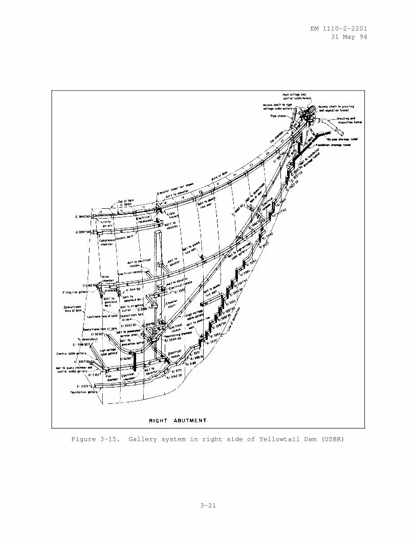
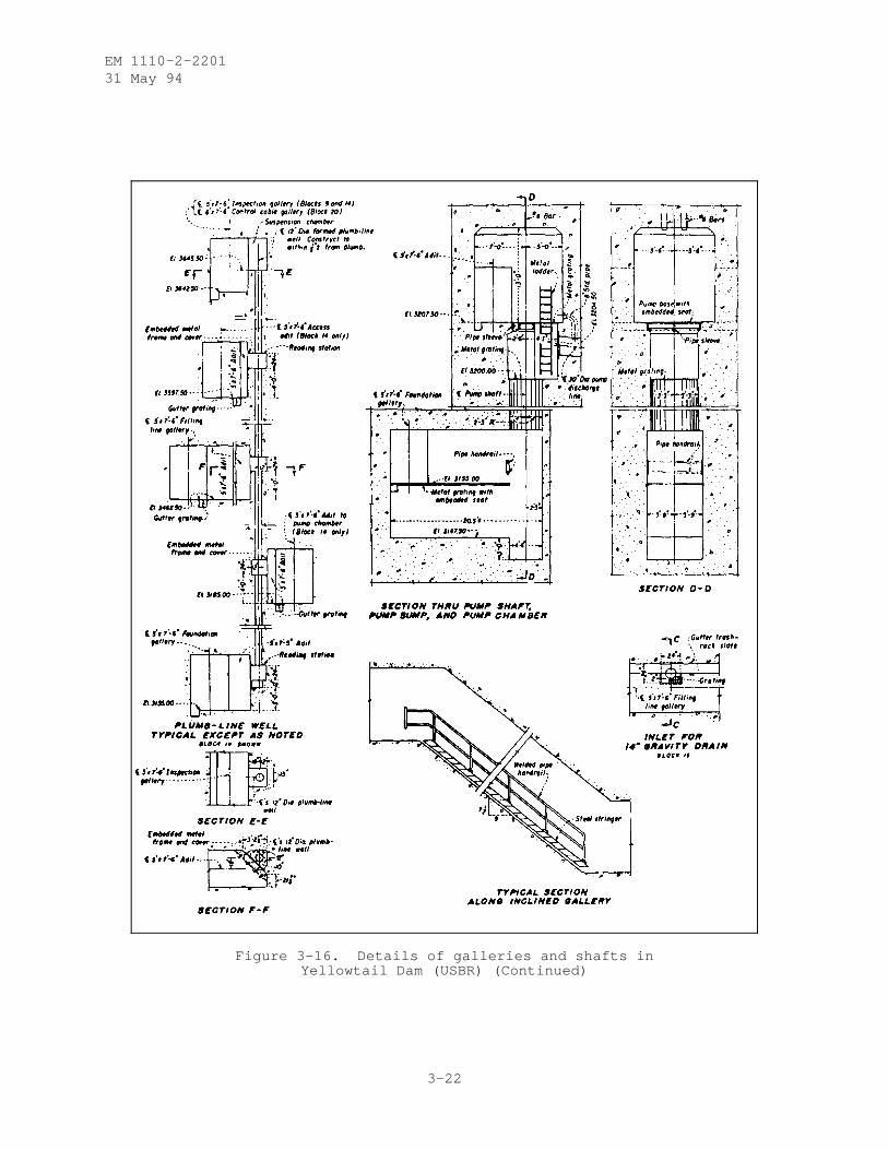
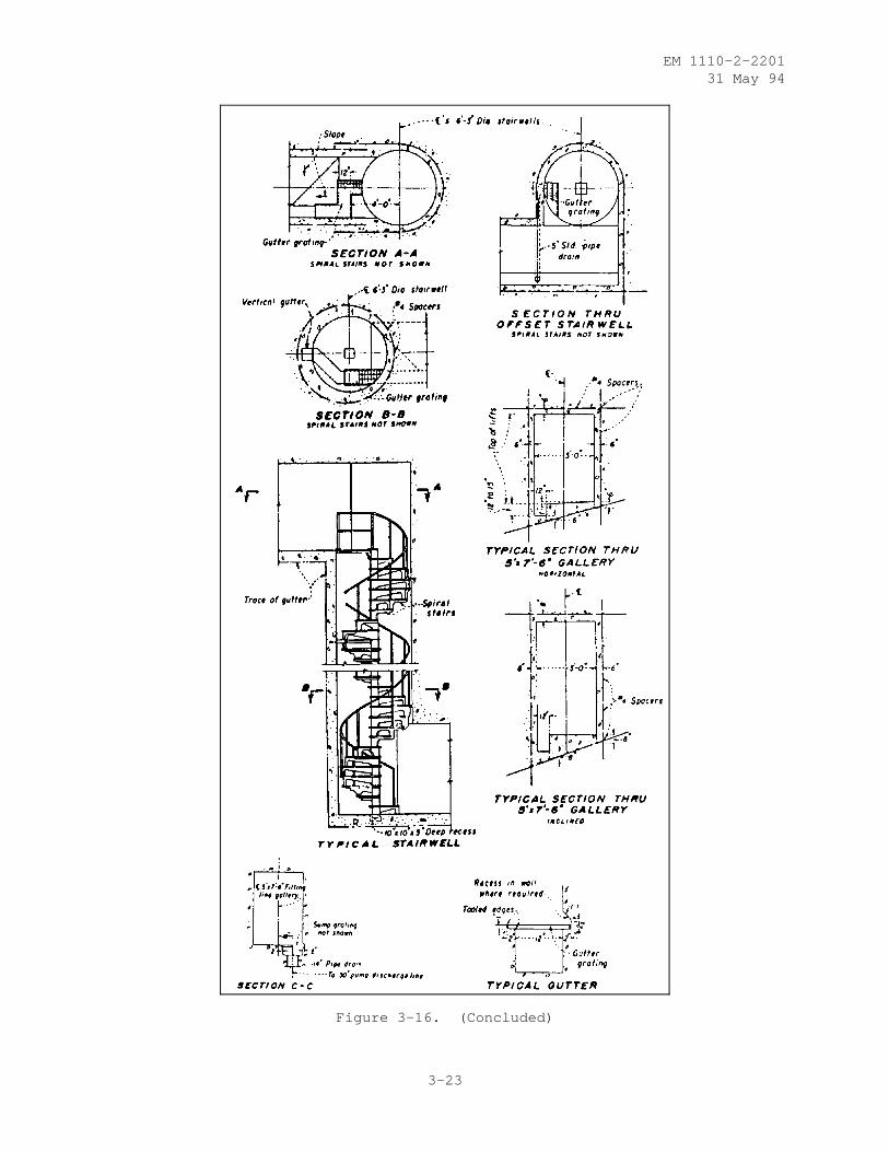
d. Galleries and Adits. A gallery is a formed opening within the damto provide access into or through the dam. Galleries are either transverse orlongitudinal and may be horizontal or on a slope as shown in Figure 3-15.Galleries connecting other galleries or connecting with other features such aspower plants, elevators, and pump chambers are called adits. Some of the morecommon uses or purposes of galleries are to provide a drainageway for waterpercolating through the upstream face or seeping through the foundation, spacefor drilling and grouting the foundation, space for headers and equipment usedin artificially cooling the concrete blocks and for grouting contractionjoints, access to the interior of the structure for observing its behavior,access to and room for mechanical and electrical equipment, access through thedam for control cables and/or power cables, and access routes for visitors, asshown in Figure 3-16. The location and size of a gallery will depend on itsintended use or purpose. The size is normally 5 feet wide by 7.5 feet high.In small, thin arch dams, galleries are not used where the radial thickness isless than five times the width. This gives the cantilevers sufficient section
3-19
EM 1110-2-220131 May 94
Figure 3-14. Typical sections at top of an arch dam (USBR)
3-20
EM 1110-2-220131 May 94
Figure 3-15. Gallery system in right side of Yellowtail Dam (USBR)
3-21
EM 1110-2-220131 May 94
Figure 3-16. Details of galleries and shafts inYellowtail Dam (USBR) (Continued)
3-22
EM 1110-2-220131 May 94
Figure 3-16. (Concluded)
3-23
EM 1110-2-220131 May 94
modulus to perform as intended. A distance of two diameters on either side ofthe gallery provides sufficient thickness to mitigate the high verticalstresses that concentrate along the gallery walls and to develop the necessarysection modulus. In thin arch dams, access galleries can be designed smallerthan 5 feet wide such as an elliptically shaped gallery 2 feet wide by 8 feethigh that contains lighting across the top, a noncorrosive grating for pedes-trian traffic, and provides space for drainage.
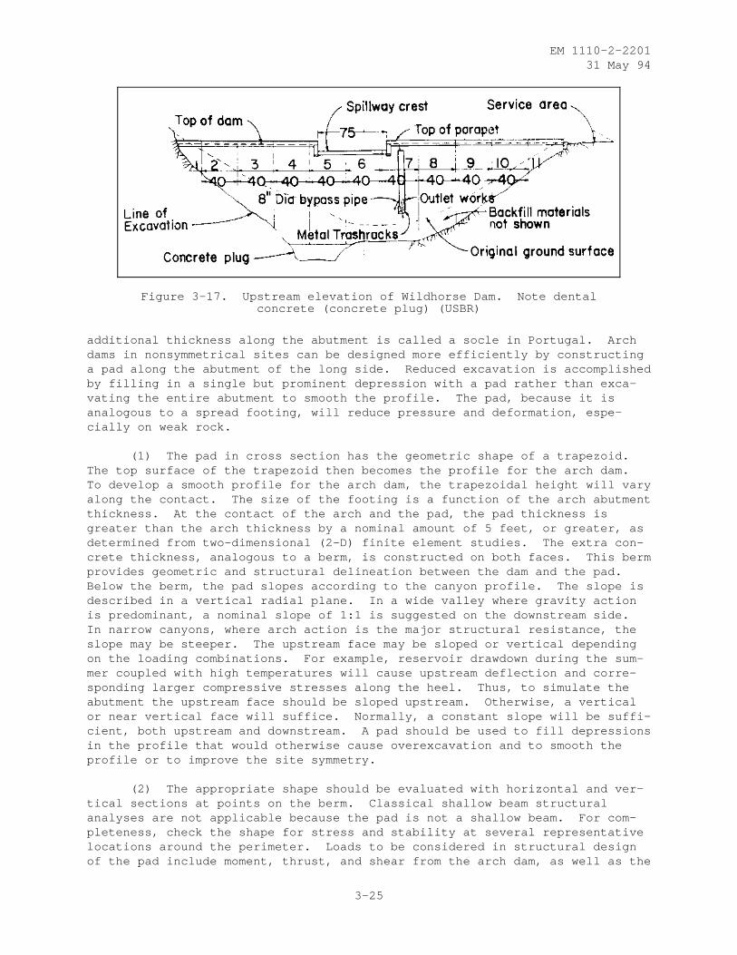
3-5. Restitution Concrete. Because of topographical and geological features,all damsites are nonsymmetrical and have an irregular profile; however, duringthe design of an arch dam, a significant saving in keyway excavation may beachieved by building up certain regions of the footprint with mass concrete toform an artificial foundation and provide a smooth perimeter for the dam. Ata particular site, restitution concrete may be local "dental" concrete, themore extensive "pad," or "thrust blocks" along the crest. In each case, thelongitudinal and transverse shape is different for different design purposes,and, accordingly, restitution concrete may be extensive upstream, downstream,or around the perimeter of the dam. In keeping with the concept of efficiencyand economy, each arch dam design should be made as geometrically simple aspossible; the optimum is a symmetrical design. With this in mind, restitutionconcrete can be added to the foundation to smooth the profile and make thesite more symmetrical, and/or provide a better distribution of stresses to thefoundation. Restitution concrete is added to the rock contact either beforeor during construction; the concrete mix is the same mass concrete used toconstruct the dam.
a. Dental Concrete. Dental concrete is used to improve local geologi-cal or topographical discontinuities that might adversely affect stability ordeformation as shown in Figure 3-17. Discontinuities include joints, seams,faults, and shattered or inferior rock uncovered during exploratory drillingor final excavation that make complete removal impractical. The necessaryamount of concrete replacement in these weak geological zones is usuallydetermined from finite element analyses in which geologic properties, geo-metric limits, and internal and/or external loads are defined. For relativelyhomogenous rock foundations with only nominal faulting or shearing, the fol-lowing approximate formulas can be used for determining the depth of dentaltreatment:
d = 0.002b H + 5 for H greater than or equal to 150 feetd = 0.3b + 5 for H less than 150 feet
where
H = height of dam above general foundation level, in feetb = width of weak zone, in feet, andd = depth of excavation of weak zone below surface of adjoining
sound rock, in feet
b. Pad. A concrete pad is added to the foundation to smooth the archdam profile, to make the site more symmetrical, to reduce excavation, and/orto provide a better distribution of stresses on the foundation. To smooth theprofile, pad concrete is placed around the arch dam perimeter, made irregulardue to topography or geology, such as in box canyons or bridging low-strengthrock types. Such treatment is not unique to the United States. The
3-24
EM 1110-2-220131 May 94
Figure 3-17. Upstream elevation of Wildhorse Dam. Note dentalconcrete (concrete plug) (USBR)
additional thickness along the abutment is called a socle in Portugal. Archdams in nonsymmetrical sites can be designed more efficiently by constructinga pad along the abutment of the long side. Reduced excavation is accomplishedby filling in a single but prominent depression with a pad rather than exca-vating the entire abutment to smooth the profile. The pad, because it isanalogous to a spread footing, will reduce pressure and deformation, espe-cially on weak rock.
(1) The pad in cross section has the geometric shape of a trapezoid.The top surface of the trapezoid then becomes the profile for the arch dam.To develop a smooth profile for the arch dam, the trapezoidal height will varyalong the contact. The size of the footing is a function of the arch abutmentthickness. At the contact of the arch and the pad, the pad thickness isgreater than the arch thickness by a nominal amount of 5 feet, or greater, asdetermined from two-dimensional (2-D) finite element studies. The extra con-crete thickness, analogous to a berm, is constructed on both faces. This bermprovides geometric and structural delineation between the dam and the pad.Below the berm, the pad slopes according to the canyon profile. The slope isdescribed in a vertical radial plane. In a wide valley where gravity actionis predominant, a nominal slope of 1:1 is suggested on the downstream side.In narrow canyons, where arch action is the major structural resistance, theslope may be steeper. The upstream face may be sloped or vertical dependingon the loading combinations. For example, reservoir drawdown during the sum-mer coupled with high temperatures will cause upstream deflection and corre-sponding larger compressive stresses along the heel. Thus, to simulate theabutment the upstream face should be sloped upstream. Otherwise, a verticalor near vertical face will suffice. Normally, a constant slope will be suffi-cient, both upstream and downstream. A pad should be used to fill depressionsin the profile that would otherwise cause overexcavation and to smooth theprofile or to improve the site symmetry.
(2) The appropriate shape should be evaluated with horizontal and ver-tical sections at points on the berm. Classical shallow beam structuralanalyses are not applicable because the pad is not a shallow beam. For com-pleteness, check the shape for stress and stability at several representativelocations around the perimeter. Loads to be considered in structural designof the pad include moment, thrust, and shear from the arch dam, as well as the
3-25
EM 1110-2-220131 May 94
reservoir pressure. The load on the massive footing for a cantilever shouldalso include its own weight. Two-dimensional FEMs are ideally suited to shapeand analyze the various loads and load combinations. Reshaping and reanalysisthen can also be easily accomplished.
(3) Construction of the pad may occur before or during construction ofthe arch dam. For example, if the foundation rock is very hard and/or mas-sive, higher-strength concrete can be placed months before the arch is con-structed. In this way, the pad concrete has time to cure and perhaps moreclosely approximate the actual foundation conditions. Or, as with the soclewhere a slightly different geometric shape is required at the arch abutmentthan at the top of the footing, the more efficient method is to construct thefooting monolithic with the arch dam, in blocks, and lifts. Special formingdetails are necessary at the berm; above and below the berm, normal slip form-ing is sufficient. Artificial cooling and contraction joint grouting is rec-ommended to avoid radial crack propagation into the dam from future shrinkageand settlement. As with the arch dam, no reinforcing steel is necessary inthe foundation shaping concrete. Longitudinal contraction joints should beavoided to prevent possible tangential crack propagation into the dam. If,during construction, a significant crack should appear in the foundation ordam concrete and continue to run through successive lifts, a proven remedy isto provide a mat of reinforcing steel on the next lift of the block with thecrack but not necessarily across contraction joints.
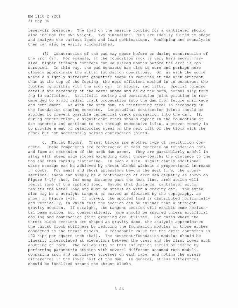
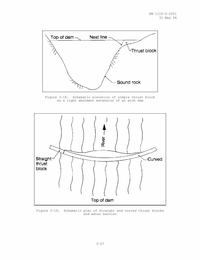
c. Thrust Blocks. Thrust blocks are another type of restitution con-crete. These components are constructed of mass concrete on foundation rockand form an extension of the arch dam crest. They are particularly useful insites with steep side slopes extending about three-fourths the distance to thetop and then rapidly flattening. In such a site, significantly additionalwater storage can be achieved by thrust blocks without a proportional increasein costs. For small and short extensions beyond the neat line, the cross-sectional shape can simply be a continuation of arch dam geometry as shown onFigure 3-18; thus, for some distance past the neat line, arch action willresist some of the applied load. Beyond that distance, cantilever actionresists the water load and must be stable as with a gravity dam. The exten-sion may be a straight tangent or curved as dictated by the topography, asshown in Figure 3-19. If curved, the applied load is distributed horizontallyand vertically, in which case the section can be thinner than a straightgravity section. If straight, the tangent section will exhibit some horizon-tal beam action, but conservatively, none should be assumed unless artificialcooling and contraction joint grouting are utilized. For cases where thethrust block sections are shaped as gravity dams, the analysis approximatesthe thrust block stiffness by reducing the foundation modulus on those archesconnected to the thrust blocks. A reasonable value for the crest abutments is100 kips per square inch (ksi). The abutment/foundation modulus should belinearly interpolated at elevations between the crest and the first lower archabutting on rock. The reliability of this assumption should be tested byperforming parametric studies with several different assumed rock moduli,comparing arch and cantilever stresses on each face, and noting the stressdifferences in the lower half of the dam. In general, stress differencesshould be localized around the thrust blocks.
3-26
EM 1110-2-220131 May 94
Figure 3-18. Schematic elevation of simple thrust blockas a right abutment extension of an arch dam
Figure 3-19. Schematic plan of straight and curved thrust blocksand water barrier
3-27
EM 1110-2-220131 May 94
CHAPTER 4
LOADING COMBINATIONS
4-1. General. Arch dams are designed for the same loads as other dams withthe exception of the temperature load which has a significant influence inarch dam design as compared to gravity dam design. The loads for which anarch dam must be designed are as follows:
a. Dead Load. Dead load is due to the weight of the concrete plus theappurtenant structures. The unit weight of the concrete is based on the labo-ratory test results of the mix design; however, for preliminary design a unitweight of 150 pounds per cubic foot (pcf) can be used. The weight of theappurtenances is normally negligible compared to the weight of the dam and maybe neglected in static design. In the case of a massive, overflow-ogee-weirspillway or massive outlet works, it may be prudent to include these struc-tures in the finite element model used for static and dynamic analyses.
b. Temperature Load. The temperature load results from the differencesbetween the closure (grouting) temperature and concrete temperatures in thedam during its operation. The closure temperature is the concrete temperatureat the time of grouting of the contraction joints. This temperature, which ineffect is the datum for all the future temperature loading, is determined fromthe results of the stress analyses of the dam under different loading combina-tions. Another way to describe the closure temperature may be to consider itas a stress-free temperature (only for dams that are grouted). For example,if an arch dam is grouted at 55 oF, there will not be any stresses due to thetemperature loading in the dam as long as the operating temperature of the damremains at 55 oF. However, once the concrete temperature exceeds 55 oF, theresulting positive temperature loading will cause compressive stresses in thearches which in turn result in deflection into the reservoir. The opposite istrue when in the winter the concrete temperature goes below 55 oF. In thiscase, the arches will experience tension which would cause deflection down-stream. The selection of the closure temperature usually involves a compro-mise between the ideal stress distribution in the dam and practical consider-ations such as the feasibility of achieving the desired closure temperature.The closure (grouting) temperature is one of the most important constructionparameters in arch dams because once the monolith joints are grouted, thestructure is assumed to become monolithic and the arch action begins. Follow-ing the determination of the closure temperature, the individual blocks shouldbe sized to prevent cracking during construction and to provide satisfactorycontraction joint opening for grouting.
(1) The following hypothetical example may help explain the role of thetemperature load - and that of the closure temperature - in arch dams. Con-sider an arch dam to be designed for a site with uniform air and water temper-atures of 65 oF, i.e., no seasonal cyclic temperature changes in the air andreservoir. Neglecting the effect of the solar radiation, the operationalconcrete temperature is then the same as that of the air and reservoir:65 oF. It is further assumed that there is no fluctuation in the reservoirlevel, so the dam is subjected to the full reservoir load at all times. Sincethe hydrostatic load in this example produces large tensile stresses along theheel of the cantilevers, the design objective would be to counteract the
4-1
EM 1110-2-220131 May 94
tensile stresses by introducing a large temperature load which would cause thecantilevers to deflect into the reservoir. This objective can be accomplishedby choosing the lowest possible closure temperature - say 35 oF - which wouldresult in a 30- oF (65 oF - 35 oF) temperature load.
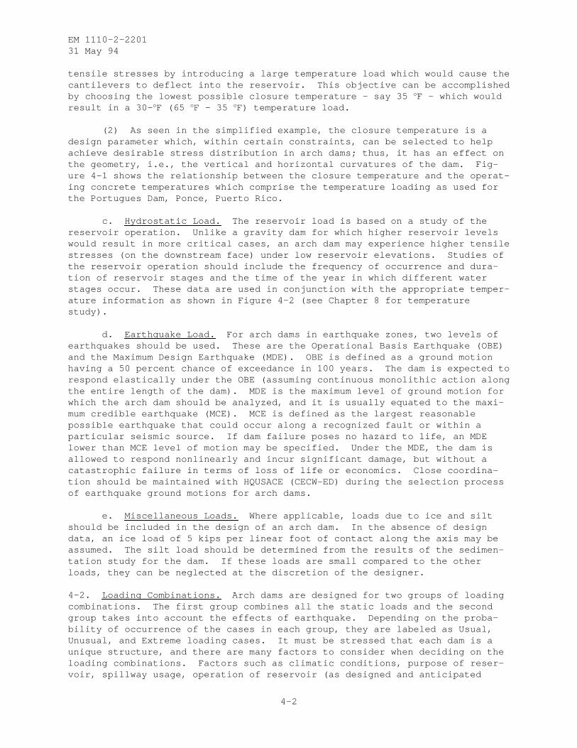
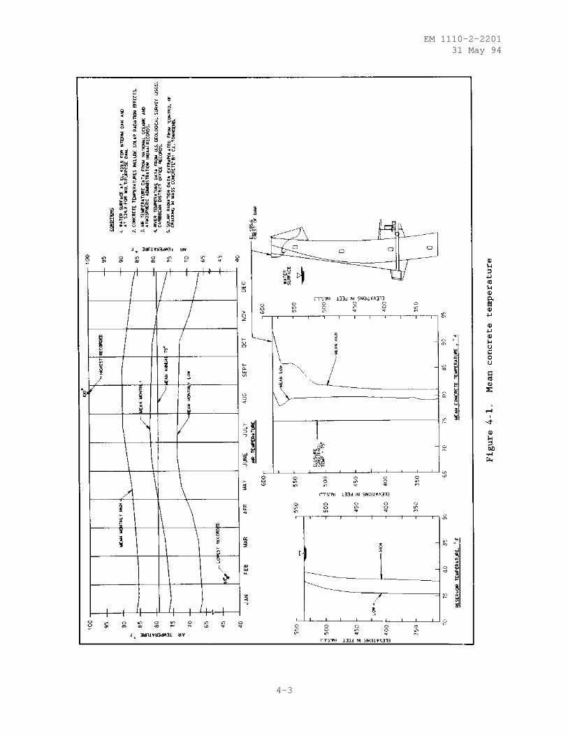
(2) As seen in the simplified example, the closure temperature is adesign parameter which, within certain constraints, can be selected to helpachieve desirable stress distribution in arch dams; thus, it has an effect onthe geometry, i.e., the vertical and horizontal curvatures of the dam. Fig-ure 4-1 shows the relationship between the closure temperature and the operat-ing concrete temperatures which comprise the temperature loading as used forthe Portugues Dam, Ponce, Puerto Rico.
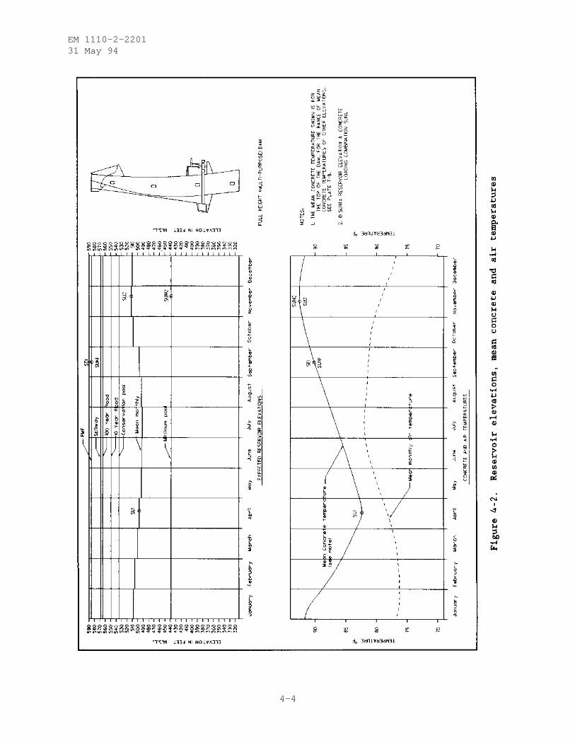
c. Hydrostatic Load. The reservoir load is based on a study of thereservoir operation. Unlike a gravity dam for which higher reservoir levelswould result in more critical cases, an arch dam may experience higher tensilestresses (on the downstream face) under low reservoir elevations. Studies ofthe reservoir operation should include the frequency of occurrence and dura-tion of reservoir stages and the time of the year in which different waterstages occur. These data are used in conjunction with the appropriate temper-ature information as shown in Figure 4-2 (see Chapter 8 for temperaturestudy).
d. Earthquake Load. For arch dams in earthquake zones, two levels ofearthquakes should be used. These are the Operational Basis Earthquake (OBE)and the Maximum Design Earthquake (MDE). OBE is defined as a ground motionhaving a 50 percent chance of exceedance in 100 years. The dam is expected torespond elastically under the OBE (assuming continuous monolithic action alongthe entire length of the dam). MDE is the maximum level of ground motion forwhich the arch dam should be analyzed, and it is usually equated to the maxi-mum credible earthquake (MCE). MCE is defined as the largest reasonablepossible earthquake that could occur along a recognized fault or within aparticular seismic source. If dam failure poses no hazard to life, an MDElower than MCE level of motion may be specified. Under the MDE, the dam isallowed to respond nonlinearly and incur significant damage, but without acatastrophic failure in terms of loss of life or economics. Close coordina-tion should be maintained with HQUSACE (CECW-ED) during the selection processof earthquake ground motions for arch dams.
e. Miscellaneous Loads. Where applicable, loads due to ice and siltshould be included in the design of an arch dam. In the absence of designdata, an ice load of 5 kips per linear foot of contact along the axis may beassumed. The silt load should be determined from the results of the sedimen-tation study for the dam. If these loads are small compared to the otherloads, they can be neglected at the discretion of the designer.
4-2. Loading Combinations. Arch dams are designed for two groups of loadingcombinations. The first group combines all the static loads and the secondgroup takes into account the effects of earthquake. Depending on the proba-bility of occurrence of the cases in each group, they are labeled as Usual,Unusual, and Extreme loading cases. It must be stressed that each dam is aunique structure, and there are many factors to consider when deciding on theloading combinations. Factors such as climatic conditions, purpose of reser-voir, spillway usage, operation of reservoir (as designed and anticipated
4-2
EM 1110-2-220131 May 94
4-3
EM 1110-2-220131 May 94
4-4
EM 1110-2-220131 May 94
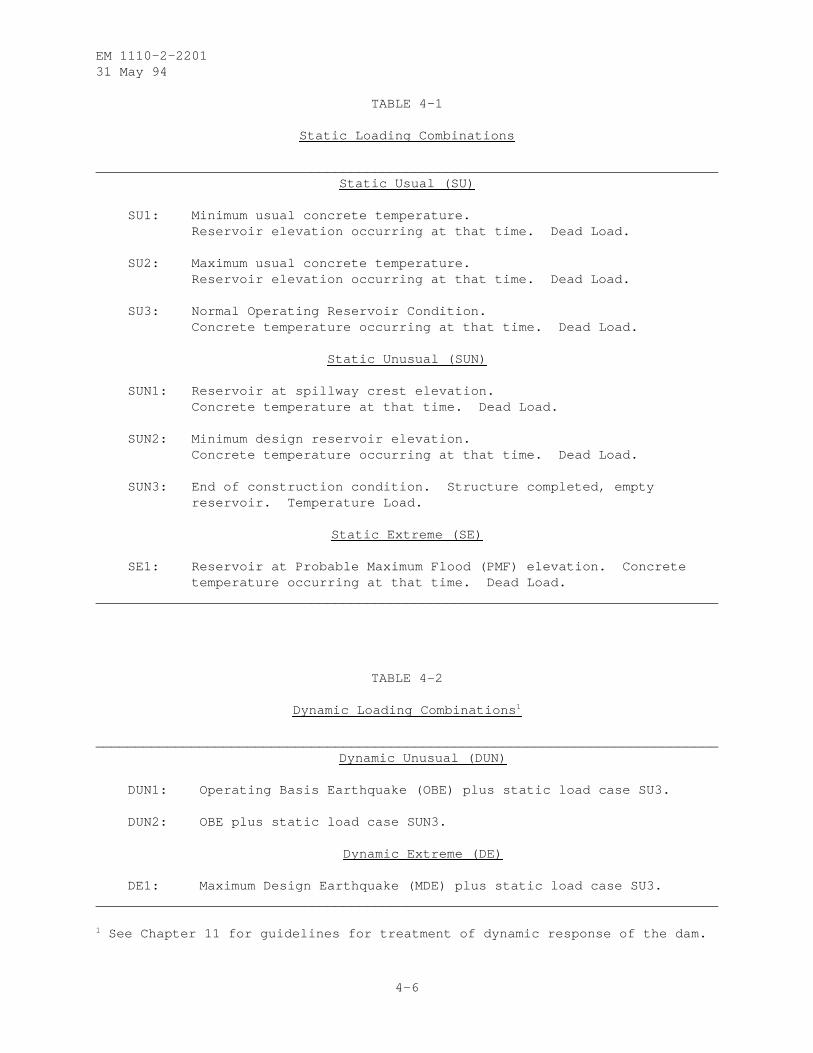
actual), and location have direct bearing on the approach taken in determiningand combining the loads and the classification of the loading combinations.Figure 4-2 illustrates the selection of the loading combinations for thePortugues Dam, Ponce, Puerto Rico. Tables 4-1 and 4-2 present the static anddynamic loading combinations which must be investigated as a minimum. Theallowables and factors of safety are discussed in Chapter 11.
4-3. Selection of Load Cases for Various Phases of Design.
a. Reconnaissance. No detailed design is required during reconnais-sance studies. The study in this phase is limited to the volume computationas discussed in Chapter 6 for the purpose of comparative studies with othertypes of dams. Of course, it is assumed that a suitable site exists for anarch dam based on the geometry of the site and the type of foundationmaterial.
b. Feasibility. Limited design work should be accomplished during thisphase of the design. From the results of the basic hydrology study, the pre-liminary loading combinations should be established and the temperature load-ing on the dam should be estimated from a study of similar projects. Basicdimensions of the dam should be determined using the procedure discussed inChapter 6 to the extent necessary to obtain the data required for stressanalysis. Only a static design analysis using two opposing loading combina-tions is required at this time. Based on the results of the stress analysis,a number of trials and adjustments in the geometry may be required to obtainacceptable stress distribution throughout the dam.
c. Preconstruction Engineering and Design (PED). Detailed design andanalysis of the dam are to be performed during the PED phase with the resultspresented in various Feature Design Memoranda (FDM). The load cases must beestablished at the earliest stages of this phase. The temperature loadingneeds to be determined from the results of the temperature study which isinitiated at beginning of PED, and the final reservoir elevations, their dura-tions, and the time of year in which these reservoir stages are expected mustbe determined in order to develop the loading combinations as shown in Fig-ure 4-2. The selection of the loads for the loading combinations should begiven careful consideration. As an example related to Figure 4-2, it is con-sidered prudent to select the middle of September for the probable maximumflood (PMF), although theoretically the PMF could happen at any time duringthe 12-month cycle. The rationale is that it is more likely for the PMF tooccur in the middle of the wet season - for this particular site - than anyother time. The significance of the above example is in the "concrete temper-ature occurring at that time," in accordance with case SE1, Table 4-1. If thePMF is assumed to happen in April when the mean concrete temperature is at itslowest, there would be a very small temperature on the dam (as shown by theclosure temperature and the mean low concrete curve in Figure 4-1) which wouldresult in too much conservatism. The opposite would be true if the PMF isassumed in November.
4-5
EM 1110-2-220131 May 94
TABLE 4-1
Static Loading Combinations
______________________________________________________________________________Static Usual (SU)
SU1: Minimum usual concrete temperature.Reservoir elevation occurring at that time. Dead Load.
SU2: Maximum usual concrete temperature.Reservoir elevation occurring at that time. Dead Load.
SU3: Normal Operating Reservoir Condition.Concrete temperature occurring at that time. Dead Load.
Static Unusual (SUN)
SUN1: Reservoir at spillway crest elevation.Concrete temperature at that time. Dead Load.
SUN2: Minimum design reservoir elevation.Concrete temperature occurring at that time. Dead Load.
SUN3: End of construction condition. Structure completed, emptyreservoir. Temperature Load.
Static Extreme (SE)
SE1: Reservoir at Probable Maximum Flood (PMF) elevation. Concretetemperature occurring at that time. Dead Load.
______________________________________________________________________________
TABLE 4-2
Dynamic Loading Combinations 1
______________________________________________________________________________Dynamic Unusual (DUN)
DUN1: Operating Basis Earthquake (OBE) plus static load case SU3.
DUN2: OBE plus static load case SUN3.
Dynamic Extreme (DE)
DE1: Maximum Design Earthquake (MDE) plus static load case SU3.______________________________________________________________________________
1 See Chapter 11 for guidelines for treatment of dynamic response of the dam.
4-6
EM 1110-2-220131 May 94
CHAPTER 5
DESIGN LAYOUT
5-1. General Design Process. Design of an arch dam involves the layout of atentative shape for the structure, preliminary static stress analysis of thislayout, evaluation of the stress results, and refinement of the arch damshape. Several iterations through the design process are necessary to producea satisfactory design which exhibits stress levels within an acceptable range.The final dam layout that evolves from the iterative design process is thenstatically analyzed by the finite element method. "Static analysis" refers tothe analysis performed after a layout has been achieved through the designprocess. "Preliminary stress analysis" refers to the method of analysisperformed during the iterative design process to investigate the state ofstress for tentative layouts. The computer program ADSAS (Arch Dam StressAnalysis System) (USBR 1975) is used for the preliminary stress analysis andis discussed in more detail in paragraph 5-5. GDAP (Graphics-based Dam Analy-sis Program) (Ghanaat 1993a) is a special purpose finite element program, spe-cifically developed for the analysis of arch dams. GDAP is discussed in moredetail in Chapter 6. Preliminary stress analyses are relatively quick andinexpensive to run compared to the static analysis which is more detailed,both in its input as well as its output. Although past history has shown thatresults from both procedures are comparable, an arch dam layout that reachesthe static analysis phase may still require refinement, pending evaluation ofstatic analysis results.
5-2. Levels of Design. There are three phases of the life cycle process of aproject for which layouts are developed; reconnaissance, feasibility, and PED.The degree of refinement for a layout is determined by the phase for which thedesign is developed.
a. Reconnaissance Phase. Of the three phases mentioned in para-graph 5-2, the least amount of engineering design effort will be expended inthe reconnaissance phase. Examination of existing topographic maps in con-junction with site visits should result in the selection of several potentialsites. When selecting sites during the reconnaissance phase, emphasis shouldbe placed on site suitability, i.e., sites with adequate canyon profiles andfoundation characteristics.
(1) Reconnaissance level layouts for different sites can be producedquickly from the empirical equations discussed in paragraph 5-4. Empiricalequations to determine concrete quantities from these layouts are presented inparagraph 5-6. Alternatively, the structural engineer may elect to basereconnaissance level layouts on previous designs which are similar in height,shape of profile, loading configuration, and for which stresses are satisfac-tory. However, it should be pointed out that most arch dams which have beenconstructed to date are single-center. Because the technology exists todaywhich simplifies the layout of more efficient, multicentered arch dams, mostdams that will be designed in the future will be of the multicentered variety.Therefore, basing a tentative, reconnaissance level layout on an existingsingle-center arch dam may result in conservative estimates of concretequantity.
5-1
EM 1110-2-220131 May 94
(2) Topographic maps or quad sheets that cover an adequate reach ofriver provide sufficient engineering data for this phase. From this region,one or more potential sites are selected. The areas around these sites areenlarged to 1:50 or 1:100 scale drawings. These enlarged topographic sheetsand the empirical formulas in paragraphs 5-4 and 5-6 will produce the geometryand concrete volume for a reconnaissance level layout.
b. Feasibility Phase. Designs during the feasibility phase are used inthe selection of the final site location and as a basis for establishing thebaseline cost estimate. Feasibility designs are made in greater detail thanreconnaissance designs since a closer approximation to final design isrequired.
(1) As a result of the work performed during the reconnaissance phase,the structural engineer should now have available one or more potential sitesto evaluate during the feasibility phase. Using the iterative layout processdiscussed in paragraph 5-4, tentative designs will be plotted, analyzed, eval-uated, and refined for each potential site until a proposed layout evolvesthat provides the best balance between minimal concrete volume and minimumstress level. Load cases to be analyzed during the feasibility phase arediscussed in Chapter 4. From the sites evaluated and their respective lay-outs, the structural engineer will select the most economical design, and thiswill be carried into the PED phase. A baseline cost estimate will be devel-oped for the final layout.
(2) The iterative layout process requires a certain amount of topo-graphic and subsurface information. However, these data should be obtainedwith the knowledge that funds for feasibility studies are limited. Aerialtopographic surveys of potential sites are required as well as a few coreborings to determine an approximation of the depth of overburden. Loadingconditions, as discussed in Chapter 4, should be defined.
c. Preconstruction Engineering and Design. Design work during thisphase is presented in the FDM which is also used to develop contract plans andspecifications. The final design layout produced during the feasibility stageis subjected to further static and dynamic analysis during the PED phase. Anyremaining load cases that have not been analyzed during the feasibility phaseshould be analyzed and evaluated at this time. This may require that anymissing data (operating conditions, thermal loads, etc.) be finalized prior tothe analysis. If results from all of the preliminary stress analysis loadcases indicate the final layout is acceptable, design may proceed to thestatic FEM analysis. Otherwise, the layout requires refinement.
5-3. Procedure. A single-center, variable-thickness, arch dam is assumed forthe purpose of discussion. The procedure for laying out other types of archdams differs only in the way the arches are defined.
5-4. Manual Layout. Although the term "Layout of an arch dam" implies asingle procedure, layout actually consists of an iterative, refining processinvolving several layouts, each successive one improving on the previous. Thefirst of these layouts require the structural designer to assume some initialparameters which will define the shape of the arch dam. As stated in para-graph 5-2a(2), a 1:50- or 1:100-scale topographic map of a dam site isrequired before layout begins. If possible, the contours should represent
5-2
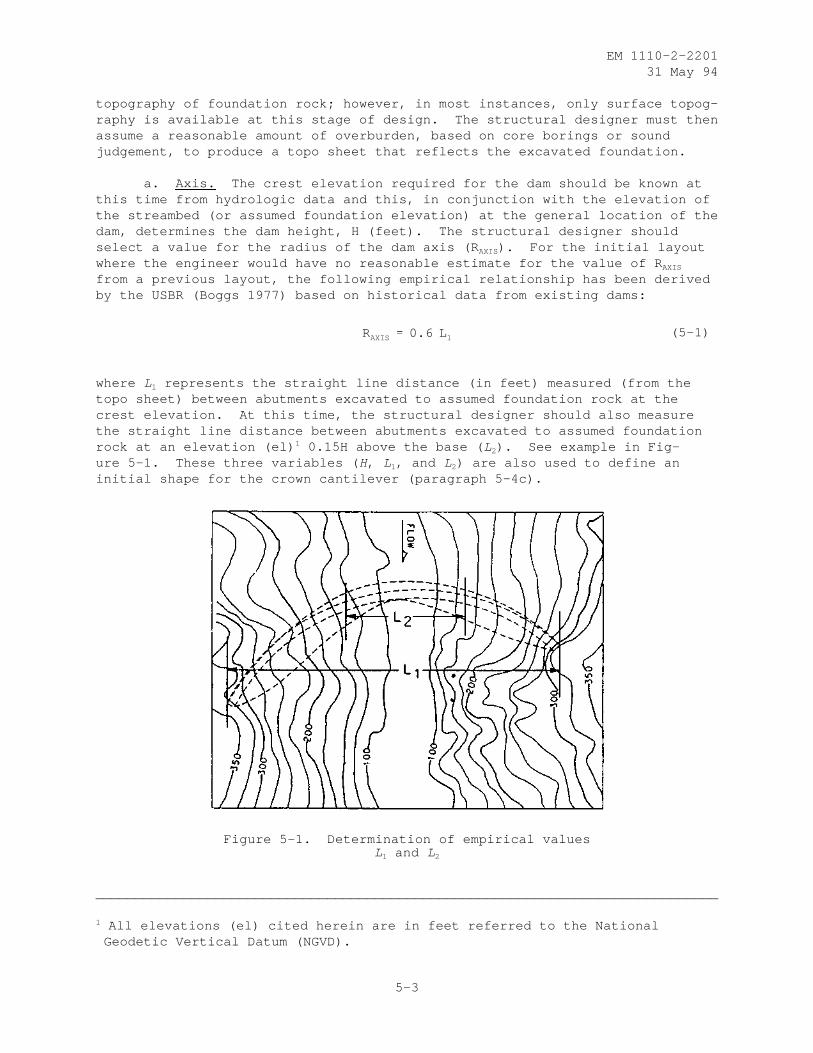
EM 1110-2-220131 May 94
topography of foundation rock; however, in most instances, only surface topog-raphy is available at this stage of design. The structural designer must thenassume a reasonable amount of overburden, based on core borings or soundjudgement, to produce a topo sheet that reflects the excavated foundation.
a. Axis. The crest elevation required for the dam should be known atthis time from hydrologic data and this, in conjunction with the elevation ofthe streambed (or assumed foundation elevation) at the general location of thedam, determines the dam height, H (feet). The structural designer shouldselect a value for the radius of the dam axis (R AXIS). For the initial layoutwhere the engineer would have no reasonable estimate for the value of R AXIS
from a previous layout, the following empirical relationship has been derivedby the USBR (Boggs 1977) based on historical data from existing dams:
(5-1)RAXIS 0.6 L 1
where L1 represents the straight line distance (in feet) measured (from thetopo sheet) between abutments excavated to assumed foundation rock at thecrest elevation. At this time, the structural designer should also measurethe straight line distance between abutments excavated to assumed foundationrock at an elevation (el) 1 0.15H above the base ( L2). See example in Fig-ure 5-1. These three variables ( H, L1, and L2) are also used to define aninitial shape for the crown cantilever (paragraph 5-4c).
Figure 5-1. Determination of empirical valuesL1 and L2
______________________________________________________________________________
1 All elevations (el) cited herein are in feet referred to the NationalGeodetic Vertical Datum (NGVD).
5-3
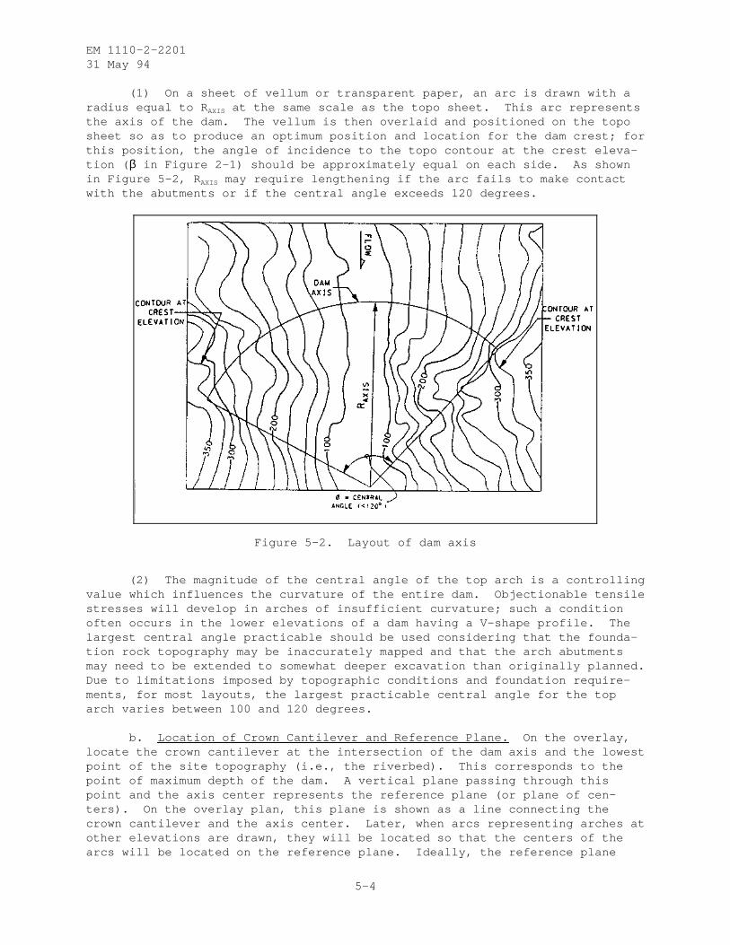
EM 1110-2-220131 May 94
(1) On a sheet of vellum or transparent paper, an arc is drawn with aradius equal to R AXIS at the same scale as the topo sheet. This arc representsthe axis of the dam. The vellum is then overlaid and positioned on the toposheet so as to produce an optimum position and location for the dam crest; forthis position, the angle of incidence to the topo contour at the crest eleva-tion ( β in Figure 2-1) should be approximately equal on each side. As shownin Figure 5-2, R AXIS may require lengthening if the arc fails to make contactwith the abutments or if the central angle exceeds 120 degrees.
Figure 5-2. Layout of dam axis
(2) The magnitude of the central angle of the top arch is a controllingvalue which influences the curvature of the entire dam. Objectionable tensilestresses will develop in arches of insufficient curvature; such a conditionoften occurs in the lower elevations of a dam having a V-shape profile. Thelargest central angle practicable should be used considering that the founda-tion rock topography may be inaccurately mapped and that the arch abutmentsmay need to be extended to somewhat deeper excavation than originally planned.Due to limitations imposed by topographic conditions and foundation require-ments, for most layouts, the largest practicable central angle for the toparch varies between 100 and 120 degrees.
b. Location of Crown Cantilever and Reference Plane. On the overlay,locate the crown cantilever at the intersection of the dam axis and the lowestpoint of the site topography (i.e., the riverbed). This corresponds to thepoint of maximum depth of the dam. A vertical plane passing through thispoint and the axis center represents the reference plane (or plane of cen-ters). On the overlay plan, this plane is shown as a line connecting thecrown cantilever and the axis center. Later, when arcs representing arches atother elevations are drawn, they will be located so that the centers of thearcs will be located on the reference plane. Ideally, the reference plane
5-4
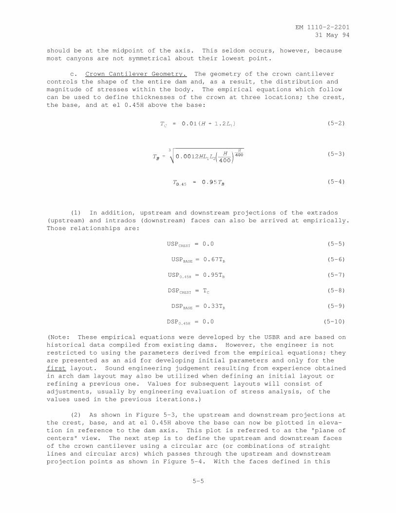
EM 1110-2-220131 May 94
should be at the midpoint of the axis. This seldom occurs, however, becausemost canyons are not symmetrical about their lowest point.
c. Crown Cantilever Geometry. The geometry of the crown cantilevercontrols the shape of the entire dam and, as a result, the distribution andmagnitude of stresses within the body. The empirical equations which followcan be used to define thicknesses of the crown at three locations; the crest,the base, and at el 0.45H above the base:
(5-2)
(5-3)
(5-4)
(1) In addition, upstream and downstream projections of the extrados(upstream) and intrados (downstream) faces can also be arrived at empirically.Those relationships are:
USPCREST = 0.0 (5-5)
USPBASE = 0.67T B (5-6)
USP0.45H = 0.95T B (5-7)
DSPCREST = TC (5-8)
DSPBASE = 0.33T B (5-9)
DSP0.45H = 0.0 (5-10)
(Note: These empirical equations were developed by the USBR and are based onhistorical data compiled from existing dams. However, the engineer is notrestricted to using the parameters derived from the empirical equations; theyare presented as an aid for developing initial parameters and only for thefirst layout. Sound engineering judgement resulting from experience obtainedin arch dam layout may also be utilized when defining an initial layout orrefining a previous one. Values for subsequent layouts will consist ofadjustments, usually by engineering evaluation of stress analysis, of thevalues used in the previous iterations.)
(2) As shown in Figure 5-3, the upstream and downstream projections atthe crest, base, and at el 0.45H above the base can now be plotted in eleva-tion in reference to the dam axis. This plot is referred to as the "plane ofcenters" view. The next step is to define the upstream and downstream facesof the crown cantilever using a circular arc (or combinations of straightlines and circular arcs) which passes through the upstream and downstreamprojection points as shown in Figure 5-4. With the faces defined in this
5-5
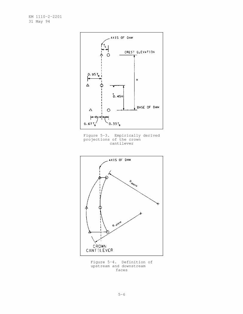
EM 1110-2-220131 May 94
Figure 5-3. Empirically derivedprojections of the crown
cantilever
Figure 5-4. Definition ofupstream and downstream
faces
5-6
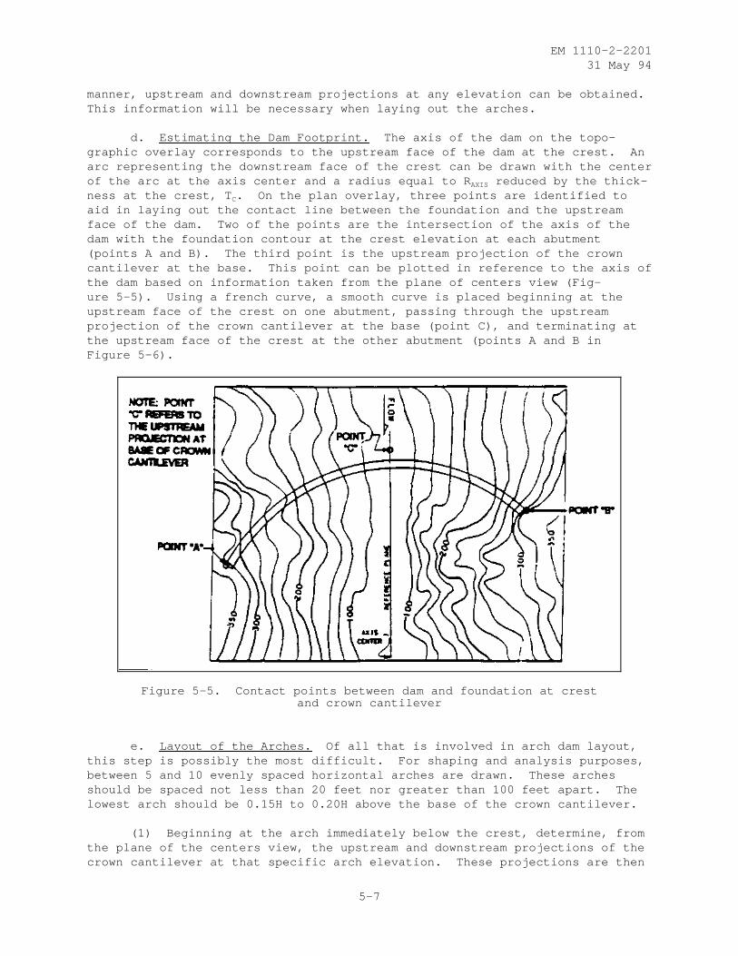
EM 1110-2-220131 May 94
manner, upstream and downstream projections at any elevation can be obtained.This information will be necessary when laying out the arches.
d. Estimating the Dam Footprint. The axis of the dam on the topo-graphic overlay corresponds to the upstream face of the dam at the crest. Anarc representing the downstream face of the crest can be drawn with the centerof the arc at the axis center and a radius equal to R AXIS reduced by the thick-ness at the crest, T C. On the plan overlay, three points are identified toaid in laying out the contact line between the foundation and the upstreamface of the dam. Two of the points are the intersection of the axis of thedam with the foundation contour at the crest elevation at each abutment(points A and B). The third point is the upstream projection of the crowncantilever at the base. This point can be plotted in reference to the axis ofthe dam based on information taken from the plane of centers view (Fig-ure 5-5). Using a french curve, a smooth curve is placed beginning at theupstream face of the crest on one abutment, passing through the upstreamprojection of the crown cantilever at the base (point C), and terminating atthe upstream face of the crest at the other abutment (points A and B inFigure 5-6).
Figure 5-5. Contact points between dam and foundation at crestand crown cantilever
e. Layout of the Arches. Of all that is involved in arch dam layout,this step is possibly the most difficult. For shaping and analysis purposes,between 5 and 10 evenly spaced horizontal arches are drawn. These archesshould be spaced not less than 20 feet nor greater than 100 feet apart. Thelowest arch should be 0.15H to 0.20H above the base of the crown cantilever.
(1) Beginning at the arch immediately below the crest, determine, fromthe plane of the centers view, the upstream and downstream projections of thecrown cantilever at that specific arch elevation. These projections are then
5-7
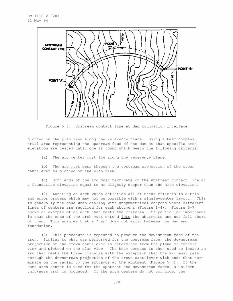
EM 1110-2-220131 May 94
Figure 5-6. Upstream contact line at dam-foundation interface
plotted on the plan view along the reference plane. Using a beam compass,trial arcs representing the upstream face of the dam at that specific archelevation are tested until one is found which meets the following criteria:
(a) The arc center must lie along the reference plane.
(b) The arc must pass through the upstream projection of the crowncantilever as plotted on the plan view.
(c) Both ends of the arc must terminate on the upstream contact line ata foundation elevation equal to or slightly deeper than the arch elevation.
(2) Locating an arch which satisfies all of these criteria is a trialand error process which may not be possible with a single-center layout. Thisis generally the case when dealing with unsymmetrical canyons where differentlines of centers are required for each abutment (Figure 1-4). Figure 5-7shows an example of an arch that meets the criteria. Of particular importanceis that the ends of the arch must extend into the abutments and not fall shortof them. This ensures that a "gap" does not exist between the dam andfoundation.
(3) This procedure is repeated to produce the downstream face of thearch. Similar to what was performed for the upstream face, the downstreamprojection of the crown cantilever is determined from the plane of centersview and plotted on the plan view. The beam compass is then used to locate anarc that meets the three criteria with the exception that the arc must passthrough the downstream projection of the crown cantilever with ends that ter-minate on the radial to the extrados at the abutment (Figure 5-7). If thesame arch center is used for the upstream and downstream faces, a uniformthickness arch is produced. If the arch centers do not coincide, the
5-8
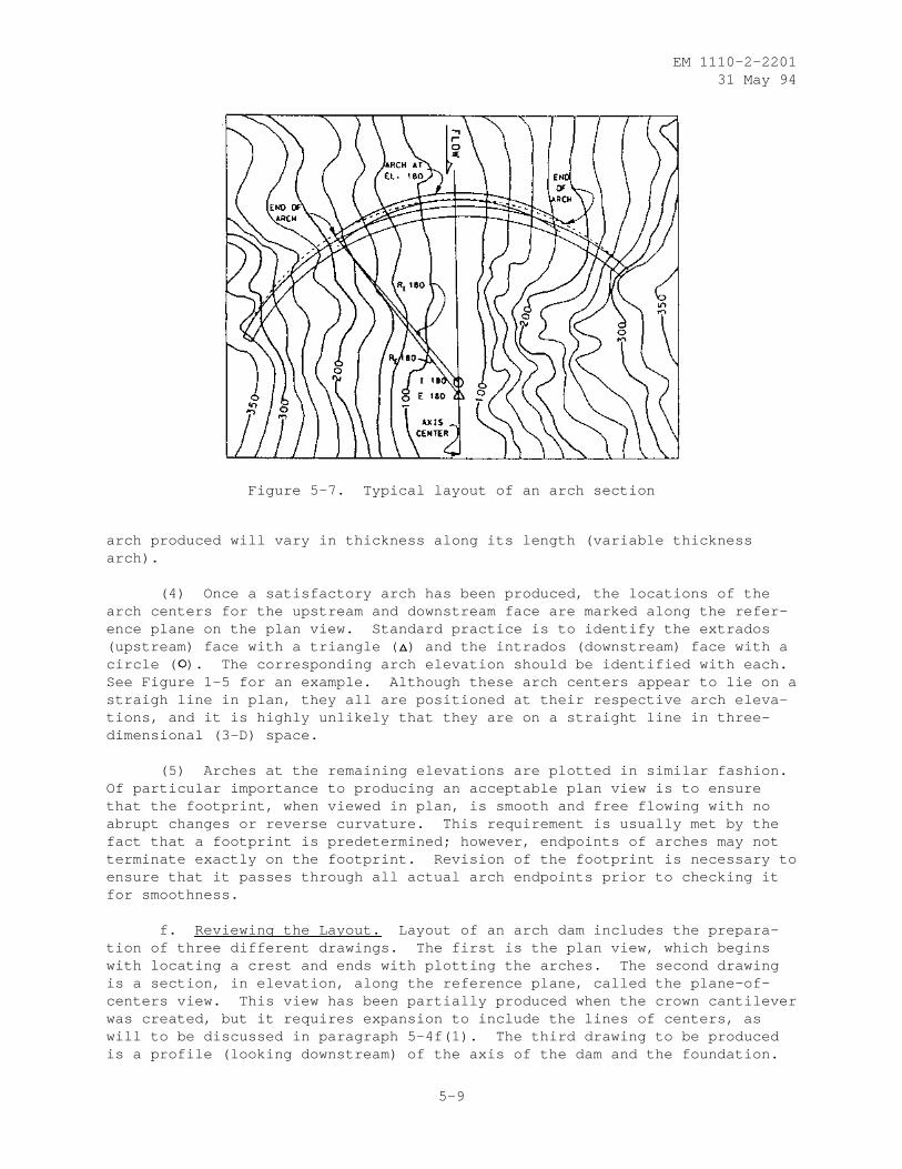
EM 1110-2-220131 May 94
Figure 5-7. Typical layout of an arch section
arch produced will vary in thickness along its length (variable thicknessarch).
(4) Once a satisfactory arch has been produced, the locations of thearch centers for the upstream and downstream face are marked along the refer-ence plane on the plan view. Standard practice is to identify the extrados(upstream) face with a triangle ( ) and the intrados (downstream) face with acircle ( ). The corresponding arch elevation should be identified with each.See Figure 1-5 for an example. Although these arch centers appear to lie on astraigh line in plan, they all are positioned at their respective arch eleva-tions, and it is highly unlikely that they are on a straight line in three-dimensional (3-D) space.
(5) Arches at the remaining elevations are plotted in similar fashion.Of particular importance to producing an acceptable plan view is to ensurethat the footprint, when viewed in plan, is smooth and free flowing with noabrupt changes or reverse curvature. This requirement is usually met by thefact that a footprint is predetermined; however, endpoints of arches may notterminate exactly on the footprint. Revision of the footprint is necessary toensure that it passes through all actual arch endpoints prior to checking itfor smoothness.
f. Reviewing the Layout. Layout of an arch dam includes the prepara-tion of three different drawings. The first is the plan view, which beginswith locating a crest and ends with plotting the arches. The second drawingis a section, in elevation, along the reference plane, called the plane-of-centers view. This view has been partially produced when the crown cantileverwas created, but it requires expansion to include the lines of centers, aswill to be discussed in paragraph 5-4f(1). The third drawing to be producedis a profile (looking downstream) of the axis of the dam and the foundation.
5-9
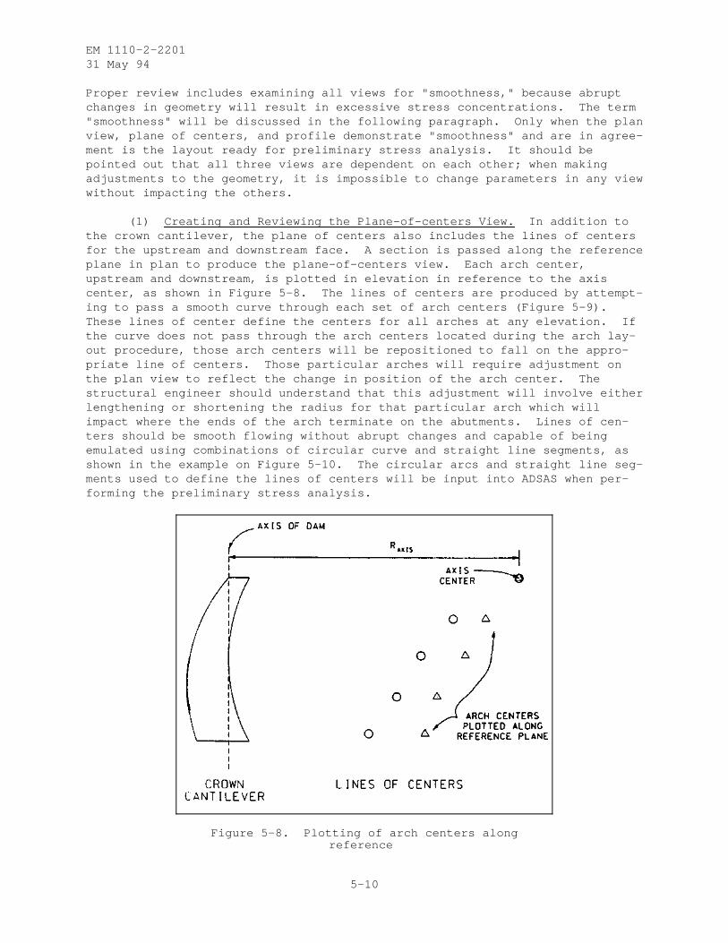
EM 1110-2-220131 May 94
Proper review includes examining all views for "smoothness," because abruptchanges in geometry will result in excessive stress concentrations. The term"smoothness" will be discussed in the following paragraph. Only when the planview, plane of centers, and profile demonstrate "smoothness" and are in agree-ment is the layout ready for preliminary stress analysis. It should bepointed out that all three views are dependent on each other; when makingadjustments to the geometry, it is impossible to change parameters in any viewwithout impacting the others.
(1) Creating and Reviewing the Plane-of-centers View. In addition tothe crown cantilever, the plane of centers also includes the lines of centersfor the upstream and downstream face. A section is passed along the referenceplane in plan to produce the plane-of-centers view. Each arch center,upstream and downstream, is plotted in elevation in reference to the axiscenter, as shown in Figure 5-8. The lines of centers are produced by attempt-ing to pass a smooth curve through each set of arch centers (Figure 5-9).These lines of center define the centers for all arches at any elevation. Ifthe curve does not pass through the arch centers located during the arch lay-out procedure, those arch centers will be repositioned to fall on the appro-priate line of centers. Those particular arches will require adjustment onthe plan view to reflect the change in position of the arch center. Thestructural engineer should understand that this adjustment will involve eitherlengthening or shortening the radius for that particular arch which willimpact where the ends of the arch terminate on the abutments. Lines of cen-ters should be smooth flowing without abrupt changes and capable of beingemulated using combinations of circular curve and straight line segments, asshown in the example on Figure 5-10. The circular arcs and straight line seg-ments used to define the lines of centers will be input into ADSAS when per-forming the preliminary stress analysis.
Figure 5-8. Plotting of arch centers alongreference
5-10
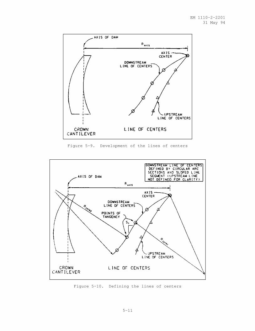
EM 1110-2-220131 May 94
Figure 5-9. Development of the lines of centers
Figure 5-10. Defining the lines of centers
5-11
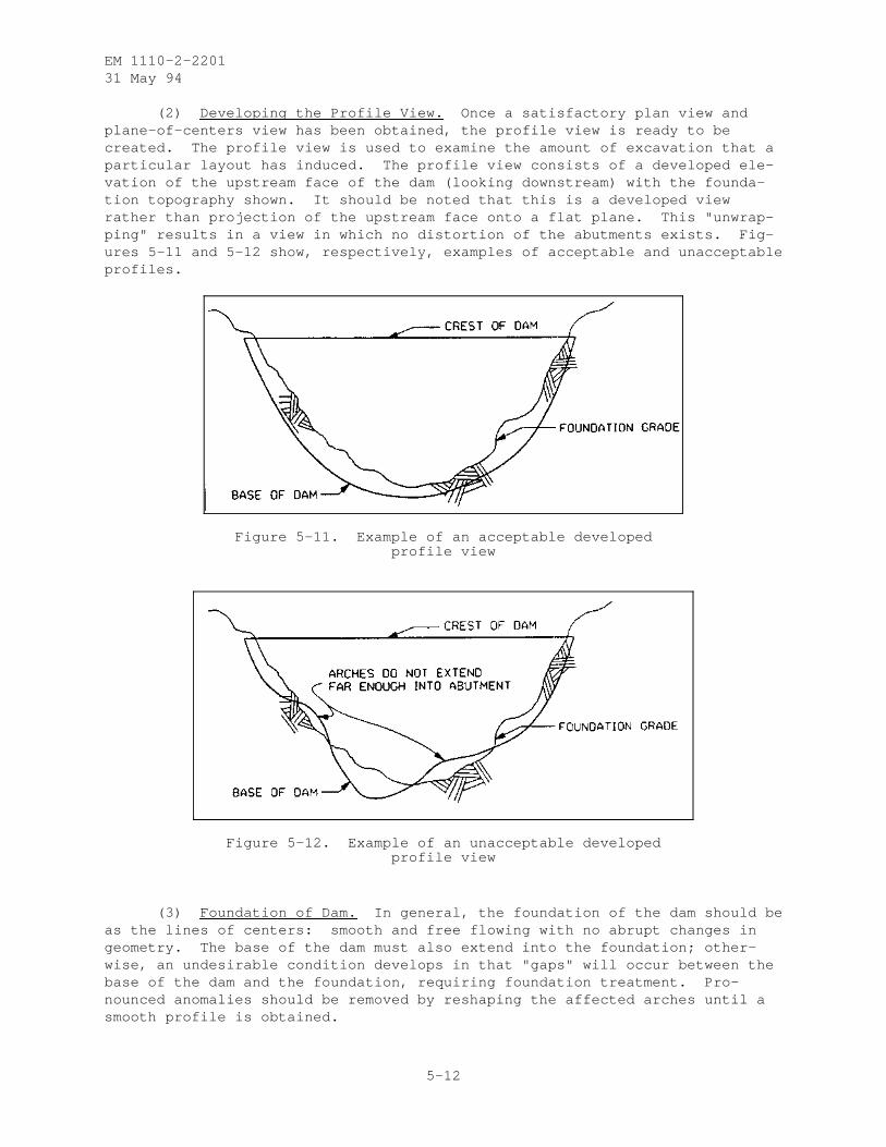
EM 1110-2-220131 May 94
(2) Developing the Profile View. Once a satisfactory plan view andplane-of-centers view has been obtained, the profile view is ready to becreated. The profile view is used to examine the amount of excavation that aparticular layout has induced. The profile view consists of a developed ele-vation of the upstream face of the dam (looking downstream) with the founda-tion topography shown. It should be noted that this is a developed viewrather than projection of the upstream face onto a flat plane. This "unwrap-ping" results in a view in which no distortion of the abutments exists. Fig-ures 5-11 and 5-12 show, respectively, examples of acceptable and unacceptableprofiles.
Figure 5-11. Example of an acceptable developedprofile view
Figure 5-12. Example of an unacceptable developedprofile view
(3) Foundation of Dam. In general, the foundation of the dam should beas the lines of centers: smooth and free flowing with no abrupt changes ingeometry. The base of the dam must also extend into the foundation; other-wise, an undesirable condition develops in that "gaps" will occur between thebase of the dam and the foundation, requiring foundation treatment. Pro-nounced anomalies should be removed by reshaping the affected arches until asmooth profile is obtained.
5-12
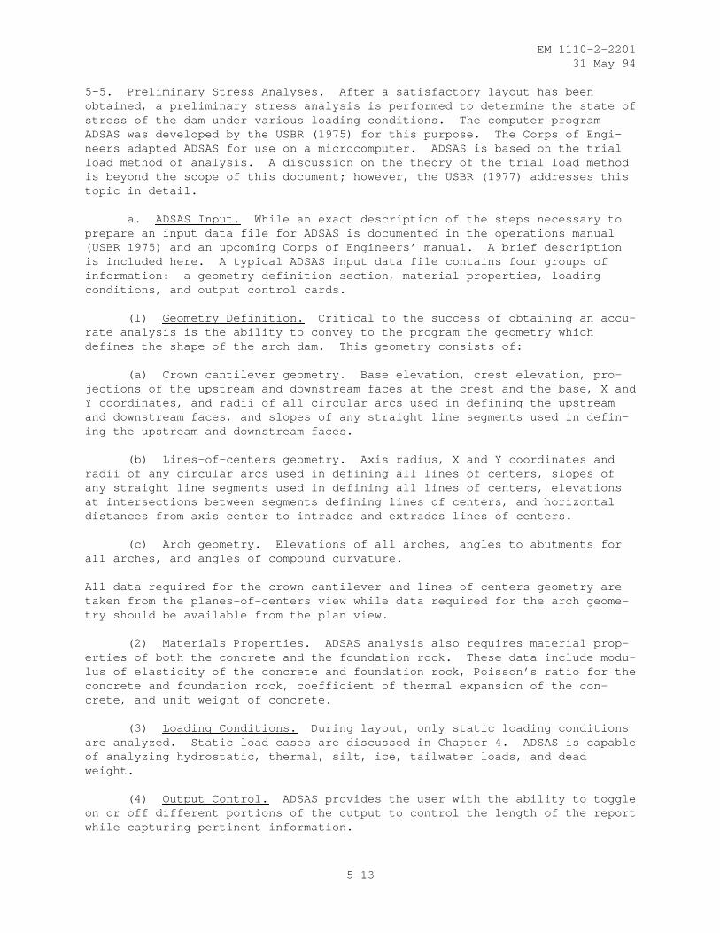
EM 1110-2-220131 May 94
5-5. Preliminary Stress Analyses. After a satisfactory layout has beenobtained, a preliminary stress analysis is performed to determine the state ofstress of the dam under various loading conditions. The computer programADSAS was developed by the USBR (1975) for this purpose. The Corps of Engi-neers adapted ADSAS for use on a microcomputer. ADSAS is based on the trialload method of analysis. A discussion on the theory of the trial load methodis beyond the scope of this document; however, the USBR (1977) addresses thistopic in detail.
a. ADSAS Input. While an exact description of the steps necessary toprepare an input data file for ADSAS is documented in the operations manual(USBR 1975) and an upcoming Corps of Engineers’ manual. A brief descriptionis included here. A typical ADSAS input data file contains four groups ofinformation: a geometry definition section, material properties, loadingconditions, and output control cards.
(1) Geometry Definition. Critical to the success of obtaining an accu-rate analysis is the ability to convey to the program the geometry whichdefines the shape of the arch dam. This geometry consists of:
(a) Crown cantilever geometry. Base elevation, crest elevation, pro-jections of the upstream and downstream faces at the crest and the base, X andY coordinates, and radii of all circular arcs used in defining the upstreamand downstream faces, and slopes of any straight line segments used in defin-ing the upstream and downstream faces.
(b) Lines-of-centers geometry. Axis radius, X and Y coordinates andradii of any circular arcs used in defining all lines of centers, slopes ofany straight line segments used in defining all lines of centers, elevationsat intersections between segments defining lines of centers, and horizontaldistances from axis center to intrados and extrados lines of centers.
(c) Arch geometry. Elevations of all arches, angles to abutments forall arches, and angles of compound curvature.
All data required for the crown cantilever and lines of centers geometry aretaken from the planes-of-centers view while data required for the arch geome-try should be available from the plan view.
(2) Materials Properties. ADSAS analysis also requires material prop-erties of both the concrete and the foundation rock. These data include modu-lus of elasticity of the concrete and foundation rock, Poisson’s ratio for theconcrete and foundation rock, coefficient of thermal expansion of the con-crete, and unit weight of concrete.
(3) Loading Conditions. During layout, only static loading conditionsare analyzed. Static load cases are discussed in Chapter 4. ADSAS is capableof analyzing hydrostatic, thermal, silt, ice, tailwater loads, and deadweight.
(4) Output Control. ADSAS provides the user with the ability to toggleon or off different portions of the output to control the length of the reportwhile capturing pertinent information.
5-13

EM 1110-2-220131 May 94
5-6. Evaluation of Results. Evaluation requires a thorough examination ofall the analytical output. Types of information to be reviewed are the crowncantilever description, intrados and extrados lines of centers, geometricalstatistics, dead load stresses and stability of blocks during construction,radial and tangential deflections and angular deformations, loading distribu-tions, arch and cantilever stresses, and principal stresses. If any aspect ofthe design is either incorrect or does not comply with established criteria,modifications must be made to improve the design.
a. Resultant Components. Evaluation of the arch dam may also includeexamination of the resultants along the abutments. These resultants are sepa-rated into three components; radial, tangential, and vertical. The combinedradial and tangential resultant should be directed into the abutment rock. Inthe lower arches, that abutment may tend to parallel the surface contours ordaylight into the canyon. Prudent engineering suggests that the resultant beturned into the abutment. The solution may be a combination of increasingstiffness in the upper arches or flexibility in the lower arches. The effectis mitigated by including the vertical component which then directs the totalresultant downward into the foundation.
b. Volume of Concrete. One major factor of a layout that requiresevaluation is the volume of concrete that is generated. ADSAS computes thisvolume as part of its output. If a quantity is desired without proceedingthrough a preliminary stress analysis (as for a reconnaissance layout), thatvalue can be arrived at empirically by the following equation (see para-graph 5-4a for definition of variables):
(5-11)v 0.000002H 2L2
(H 0.8L 2)L1 L2
0.0004HL 1[H L1]
The volume of concrete calculated in ADSAS or derived from Equation 5-11 doesnot reflect mass concrete in thrust blocks, flip buckets, spillways, or otherappurtenances.
5-7. Improvement of Design. The best of alternative designs will havestresses distributed as uniformly as possible within allowable limits combinedwith a minimum of concrete. Where to terminate a design and accept a finallayout based on these criteria are difficult in some dams with widely varyingloading conditions, such as with a flood control dam which has periods of lowand high reservoir elevations. The primary means of effecting changes in thebehavior of the dam is by adjusting the shape of the structure. Whenever theoverall stress level in the structure is far below the allowable limits, con-crete volume can be reduced, thereby utilizing the remaining concrete moreefficiently and improving the economy. Following are some examples of how adesign can be improved by shaping.
a. Loads and Deflections. Load distribution and deflection patternsshould vary smoothly from point to point. Often when an irregular patternoccurs, it is necessary to cause load to be shifted from the vertical canti-lever units to the horizontal arches. Such a transfer can be produced bychanging the stiffness of the cantilever relative to the arch.
5-14
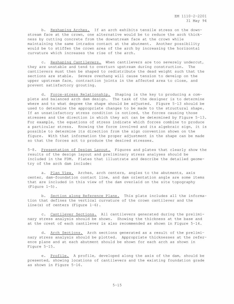
EM 1110-2-220131 May 94
b. Reshaping Arches. If an arch exhibits tensile stress on the down-stream face at the crown, one alternative would be to reduce the arch thick-ness by cutting concrete from the downstream face at the crown whilemaintaining the same intrados contact at the abutment. Another possibilitywould be to stiffen the crown area of the arch by increasing the horizontalcurvature which increases the rise of the arch.
c. Reshaping Cantilevers. When cantilevers are too severely undercut,they are unstable and tend to overturn upstream during construction. Thecantilevers must then be shaped to redistribute the dead weight such that thesections are stable. Severe overhang will cause tension to develop on theupper upstream face, contraction joints in the affected area to close, andprevent satisfactory grouting.
d. Force-stress Relationship. Shaping is the key to producing a com-plete and balanced arch dam design. The task of the designer is to determinewhere and to what degree the shape should be adjusted. Figure 5-13 should beused to determine the appropriate changes to be made to the structural shape.If an unsatisfactory stress condition is noticed, the forces causing thosestresses and the direction in which they act can be determined by Figure 5-13.For example, the equations of stress indicate which forces combine to producea particular stress. Knowing the force involved and its algebraic sign, it ispossible to determine its direction from the sign convention shown on thefigure. With that information the proper adjustment in the shape can be madeso that the forces act to produce the desired stresses.
5-8. Presentation of Design Layout. Figures and plates that clearly show theresults of the design layout and preliminary stress analyses should beincluded in the FDM. Plates that illustrate and describe the detailed geome-try of the arch dam include:
a. Plan View. Arches, arch centers, angles to the abutments, axiscenter, dam-foundation contact line, and dam orientation angle are some itemsthat are included in this view of the dam overlaid on the site topography(Figure 1-5).
b. Section along Reference Plane. This plate includes all the informa-tion that defines the vertical curvature of the crown cantilever and theline(s) of centers (Figure 1-6).
c. Cantilever Sections. All cantilevers generated during the prelimi-nary stress analysis should be shown. Showing the thickness at the base andat the crest of each cantilever is also recommended as shown in Figure 5-14.
d. Arch Sections. Arch sections generated as a result of the prelimi-nary stress analysis should be plotted. Appropriate thicknesses at the refer-ence plane and at each abutment should be shown for each arch as shown inFigure 5-15.
e. Profile. A profile, developed along the axis of the dam, should bepresented, showing locations of cantilevers and the existing foundation gradeas shown in Figure 5-16.
5-15
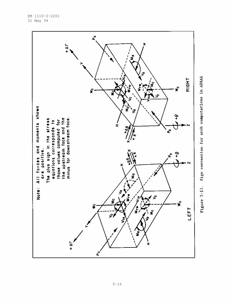
EM 1110-2-220131 May 94
5-16
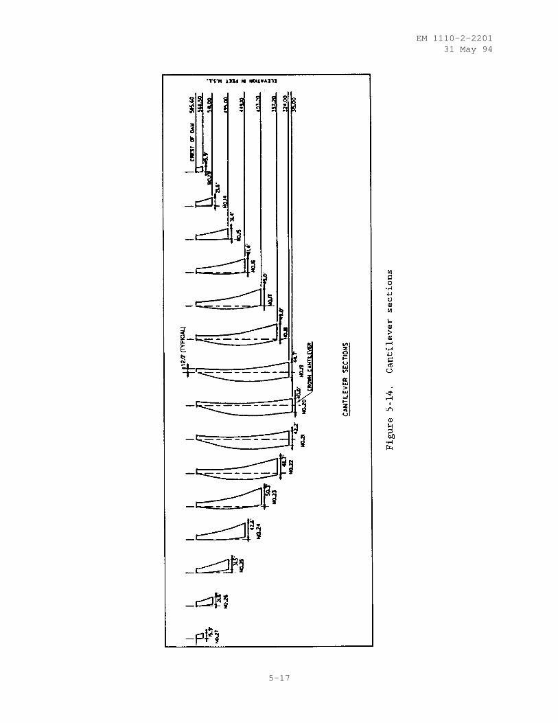
EM 1110-2-220131 May 94
5-17
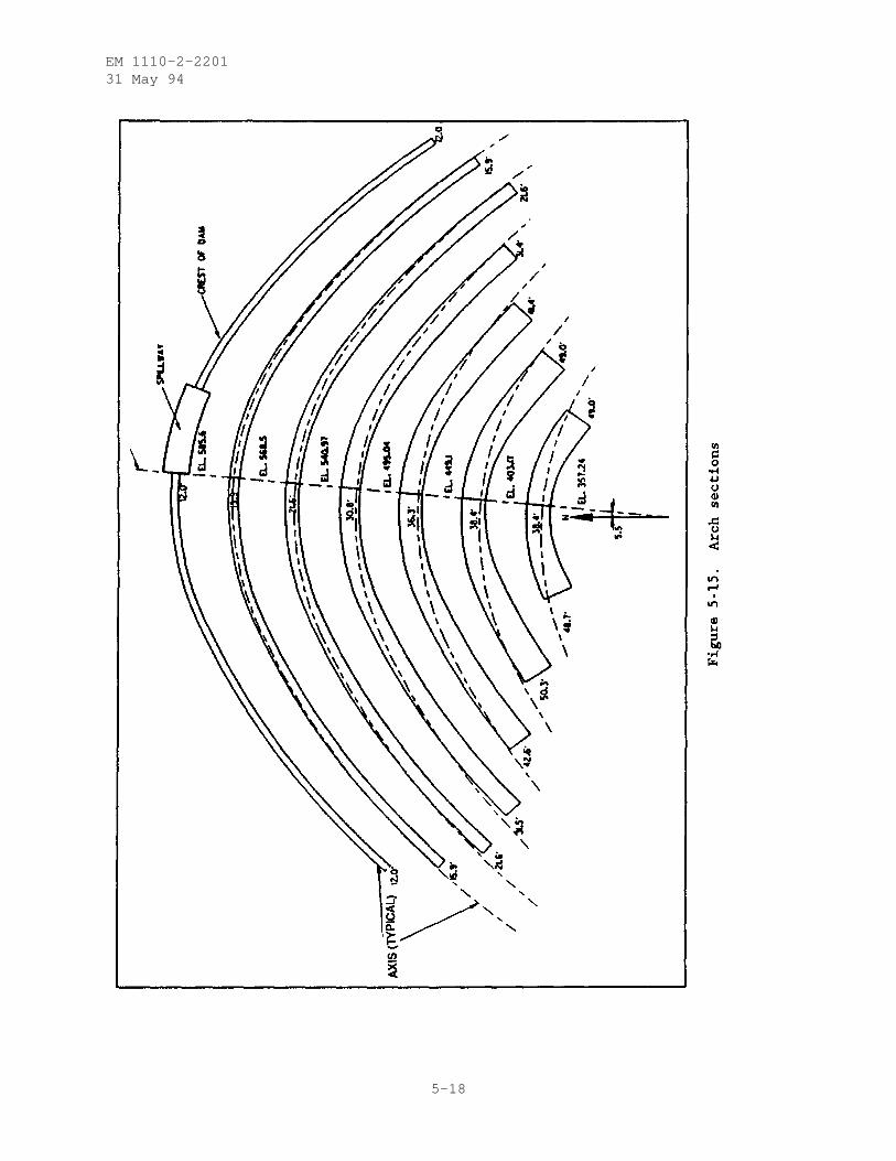
EM 1110-2-220131 May 94
5-18
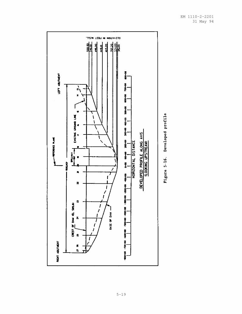
EM 1110-2-220131 May 94
5-19
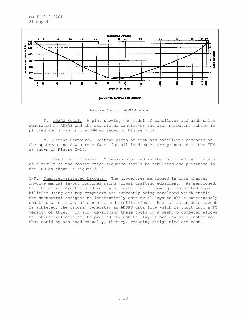
EM 1110-2-220131 May 94
Figure 5-17. ADSAS model
f. ADSAS Model. A plot showing the model of cantilever and arch unitsgenerated by ADSAS and the associated cantilever and arch numbering scheme isplotted and shown in the FDM as shown in Figure 5-17.
g. Stress Contours. Contour plots of arch and cantilever stresses onthe upstream and downstream faces for all load cases are presented in the FDMas shown in Figure 5-18.
h. Dead Load Stresses. Stresses produced in the ungrouted cantileversas a result of the construction sequence should be tabulated and presented inthe FDM as shown in Figure 5-19.
5-9. Computer-assisted Layouts. The procedures mentioned in this chapterinvolve manual layout routines using normal drafting equipment. As mentioned,the iterative layout procedure can be quite time consuming. Automated capa-bilities using desktop computers are currently being developed which enablethe structural designer to interactively edit trial layouts while continuouslyupdating plan, plane of centers, and profile views. When an acceptable layoutis achieved, the program generates an ADSAS data file which is input into a PCversion of ADSAS. In all, developing these tools on a desktop computer allowsthe structural designer to proceed through the layout process at a faster ratethan could be achieved manually, thereby, reducing design time and cost.
5-20
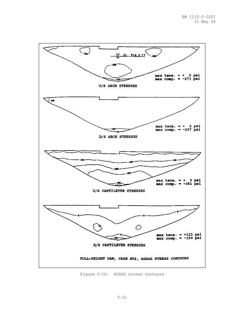
EM 1110-2-220131 May 94
Figure 5-18. ADSAS stress contours
5-21
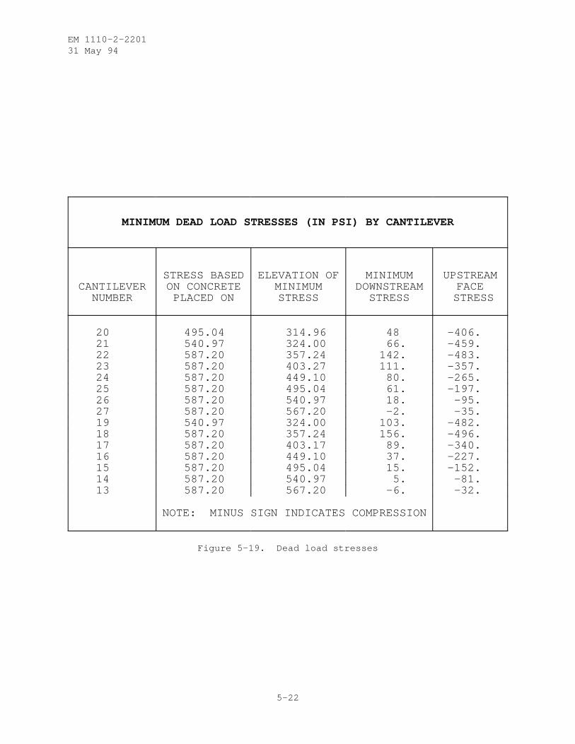
EM 1110-2-220131 May 94
MINIMUM DEAD LOAD STRESSES (IN PSI) BY CANTILEVER
CANTILEVERNUMBER
STRESS BASEDON CONCRETE
PLACED ON
ELEVATION OFMINIMUMSTRESS
MINIMUMDOWNSTREAM
STRESS
UPSTREAMFACE
STRESS
20 495.04 314.96 48 -406.21 540.97 324.00 66. -459.22 587.20 357.24 142. -483.23 587.20 403.27 111. -357.24 587.20 449.10 80. -265.25 587.20 495.04 61. -197.26 587.20 540.97 18. -95.27 587.20 567.20 -2. -35.19 540.97 324.00 103. -482.18 587.20 357.24 156. -496.17 587.20 403.17 89. -340.16 587.20 449.10 37. -227.15 587.20 495.04 15. -152.14 587.20 540.97 5. -81.13 587.20 567.20 -6. -32.
NOTE: MINUS SIGN INDICATES COMPRESSION
Figure 5-19. Dead load stresses
5-22
EM 1110-2-220131 May 94
CHAPTER 6
STATIC ANALYSIS
6-1. Introduction. This chapter describes static analysis of concrete archdams using the FEM. The purpose of FEM analysis is to perform more accurateand realistic analysis by eliminating many assumptions made in the traditionalmethods. The main advantages of FEM are its versatility and its ability forexploring foundation conditions and representing the more realistic interac-tion of dam and foundation rock. In particular, nonhomogeneous rock proper-ties, weak zones, clay or gouge seams, and discontinuities in the foundationmay be considered in the analysis to evaluate their effects on the stressdistribution. The cracked sections or open joints in the structure can bemodeled; thrust blocks and the spillway openings in the crest are appropri-ately included in the mathematical models; and the stresses around the galler-ies and other openings can be investigated.
6-2. Design Data Required. Design data needed for structural analysis of aconcrete arch dam are: Poisson’s ratio, strength and elastic properties ofthe concrete, Poisson’s ratio and deformation modulus of the foundation rock,unit weight and coefficient of thermal expansion of the concrete, geometricdata of the dam layout, geometric data of spillway openings and thrust blocks,operating reservoir and tailwater surfaces, temperature changes within thedam, probable sediment depth in the reservoir, probable ice load, and theuplift pressure. A description of each data type is as follows:
a. Concrete Properties. The material properties of the concrete foruse in static analysis are influenced by mix proportions, cement, aggregate,admixtures, and age. These data are not available beforehand and should beestimated based on published data and according to experience in similardesign and personal judgment; however, actual measured data should be used inthe final analysis as they become available. The concrete data needed for theanalysis are:
(1) Sustained modulus of elasticity
(2) Poisson’s ratio
(3) Unit weight
(4) Compressive strength
(5) Tensile strength
(6) Coefficient of thermal expansion
The sustained modulus of elasticity is used in the analyses of the staticloads to account for the creep effects. In the absence of long-term testdata, a sustained modulus of elasticity equal to 60 to 70 percent of theinstantaneous modulus may be used. The standard test method for measurementof the concrete properties is given in Chapter 9.
6-1
EM 1110-2-220131 May 94
b. Foundation Properties. The foundation data required for structuralanalysis are Poisson’s ratio and the deformation modulus of the rock support-ing the arch dam. Deformation modulus is defined as the ratio of appliedstress to resulting elastic plus inelastic strains and thus includes theeffects of joints, shears, and faults. Deformation modulus is obtained byin situ tests (Structural Properties, Chapter 9) or is estimated from elasticmodulus of the rock using a reduction factor (Von Thun and Tarbox 1971 (Oct)).If more than one material type is present in the foundation, an effectivedeformation modulus should be used instead. For nonhomogeneous foundations,several effective deformation modulus values may be needed to adequatelydefine the foundation characteristics.
c. Geometric Data. The necessary data for constructing a finiteelement mesh of an arch dam is obtained from drawings containing informationdefining the geometry of the dam shape. These include the plan view and sec-tion along the reference plane, as shown in Figures 1-5 and 1-6. In practice,arch dams are geometrically described as multicentered arches with their cen-ters varied by elevation in addition to the arch opening angles and radiivarying for each side with elevation. Elliptical arch shapes may be approxi-mated for the various elevations by three-centered arches including centralsegments with shorter radii and two outer segments with equal but longerradii. The basic geometric data of a multicentered dam at each elevation forthe upstream and downstream faces are as follows:
(1) Radius of central arcs
(2) Radius of outer arcs
(3) Angles to point of compounding curvatures
(4) Angles to abutments
(5) Location of centers of central arcs
Preparation of finite element mesh data from these geometric data is very timeconsuming because most general-purpose finite element programs cannot directlyhandle these data or the similar ADSAS input data; however, GDAP (Ghanaat1993a), a specialized arch dam analysis program, can automatically generatecoordinates of all nodal points, element data, element distributed loads, andthe nodal boundary conditions from such limited geometric data or evendirectly from ADSAS input data for any arch dam-foundation system. Geometricdata for modeling thrust blocks, spillway openings, and other structural fea-tures are obtained directly from the associated design drawings.
d. Static Loads. The basic loads contributing to the design or safetyanalysis of arch dams are gravity, reservoir water, temperature changes, silt,ice, uplift, and earthquake loads. The data needed to specify each individualstatic load are described in this section. Earthquake loads and their effectsare discussed in Chapter 7, and the various load combinations are presented inChapter 4.
(1) Gravity Loads. Gravity loads due to weight of the material arecomputed from the unit weight and geometry of the finite elements. The deadweight may be applied either to free-standing cantilevers without arch action
6-2
EM 1110-2-220131 May 94
to simulate the construction process or to the monolithic arch structure withall the contraction joints grouted. Although the first assumption usually ismore appropriate, a combination of the two is more realistic in situationswhere the vertical curvature of the cantilevers is so pronounced that it isnecessary to limit the height of free-standing cantilevers by grouting thelower part of the dam. In those cases, a gravity load analysis which closelyfollows the construction sequence is more representative. The weight of theappurtenant structures that are not modeled as part of the finite elementmodel but are supported by the dam, if significant, are input as externalconcentrated loads and are applied to the supporting nodal points.
(2) Reservoir Water. Most finite element programs such as the GDAP andSAP-IV handle hydrostatic loads as distributed surface loads. The surfaceloads are then applied to the structure as concentrated nodal loads. There-fore, hydrostatically varying surface pressure can be specified by using areference fluid surface and a fluid weight density as input.
(3) Temperature. Temperature data needed in structural analysis resultfrom the differences between the closure temperature and concrete temperatureexpected in the dam during its operation. Temperature changes include highand low temperature conditions and usually vary: by elevation, across thearch, and in the upstream-downstream direction. Temperature distribution inthe concrete is determined by temperature studies (Chapter 8) considering theeffects of transient air and water temperatures, fluctuation of reservoirlevel, and the solar radiation. The nonlinear temperature distribution cal-culated in these studies is approximated by straight line distribution throughthe dam thickness for the use in structural analysis performed in using shellelements. However, if several solid elements are used through the thickness,a nonlinear temperature distribution can be approximated.
(4) Silt. Arch dams often are subjected to silt pressures due to sedi-mentary materials deposited in the reservoir. The saturated silt loads aretreated as hydrostatically varying pressures acting on the upstream face ofthe dam and on the valley floor. A silt reference level and the weight den-sity of the equivalent fluid are needed to specify the silt pressures.
(5) Ice. Ice pressure can exert a significant load on dams located athigh altitudes and should be considered as a design load when the ice cover isrelatively thick. The actual ice pressure is very difficult to estimatebecause it depends on a number of parameters that are not easily available.In that case, an estimate of ice pressure as given in Chapter 4 may be used.
(6) Uplift. The effects of uplift pressures on stress distribution inthin arch dams are negligible and, thus, may be ignored; however, uplift canhave a significant influence on the stability of a thick gravity-arch dam andshould be considered in the analysis. For more discussion on the subject,refer to "Theoretical Manual for Analysis of Arch Dams" (Ghanaat 1993b).
6-3. Method of Analysis. The static analysis of an arch dam should be basedon the 3-D FEM. The FEM is capable of representing the actual 3-D behavior ofan arch dam-foundation system and can handle any arbitrary geometry of the damand valley shape. Furthermore, the method can account for a variety of loadsand is equally applicable to gravity arch sections as well as to slender anddoubly curved arch dam structures.
6-3
EM 1110-2-220131 May 94
a. The FEM is essentially a procedure by which a continuum such as anarch dam structure is approximated by an assemblage of discrete elementsinterconnected only at a finite number of nodal points having a finite numberof unknowns. Although various formulations of the FEM exist today, only thedisplacement-based formulation which is the basis for almost all major practi-cal structural analysis programs is described briefly here. The displacement-based FEM is an extension of the displacement method that was used extensivelyfor the analysis of the framed and truss type structures before the FEM wasdeveloped (Przemieniecki 1968). Detailed formulations of the FEM are given byZienkiewicz (1971), Cook (1981), and Bathe and Wilson (1976). Application ofthe method to the analysis of arch dams is presented in the "TheoreticalManual for Analysis of Arch Dams" (Ghanaat 1993b). Following is an outline ofthe finite element computer analysis for static loads, as a sequence of ana-lytical steps:
(1) Divide the dam structure and the foundation rock into an appropri-ate number of discrete subregions (finite elements) connected at joints callednodal points. For a discussion of mesh density, see paragraph 6-4.
(2) Compute the stiffness matrix of each individual element accordingto the nodal degrees of freedom and the force-displacement relationshipsdefining the element.
(3) Add the stiffness matrices of the individual elements to form thestiffness matrix of the complete structure (direct stiffness method).
(4) Define appropriate boundary conditions and establish equilibriumconditions at the nodal points. The resulting system of equations for theassembled structure may be expressed as:
(6-1)ku p
where
k = stiffness matrixu = displacement vectorp = load vector
(5) Solve the system of equations for the unknown nodal displacementsu.
(6) Calculate element stresses from the relationship between the ele-ment strains and the nodal displacements assuming an elastic strain-stressrelationship.
b. Most general-purpose finite element computer programs follow theseabove analytical steps for static structural analysis, but their applicabilityto arch dams may be judged by whether they have the following characteristics:
(1) An efficient graphics-based preprocessor with automatic mesh gener-ation capabilities to facilitate development of mathematical models and tocheck the accuracy of input data.
6-4
EM 1110-2-220131 May 94
(2) Efficient and appropriate finite element types for realistic repre-sentation of the various components of the dam structure.
(3) Efficient programming methods and numerical techniques appropriatefor the solution of large systems with many degrees of freedom.
(4) Postprocessing capabilities providing graphics for evaluation andpresentation of the results.
c. SAP-IV (Bathe, Wilson, and Peterson 1974) and GDAP (Ghanaat 1993a)are two widely used programs for the analysis of arch dams. These programsare briefly described here. SAP-IV is a general-purpose finite element com-puter program for the static and dynamic analysis of linearly elastic struc-tures and continua. This program has been designed for the analysis of largestructural systems. Its element library for dam analysis includes eight-nodeand variable-number-node, 3-D solid elements. The program can handle variousstatic loads including hydrostatic pressures, temperature, gravity due toweight of the material, and concentrated loads applied at the nodal points.However, the program lacks pre- and postprocessing capabilities. Thus, finiteelement meshes of the dam and foundation must be constructed manually from theinput nodal coordinates and element connectivities. Also, the computed stressresults are given in the direction of local or global axes and cannot beinterpreted reliably unless they are transformed into dam surface arch andcantilever stresses by the user.
d. GDAP has been specifically designed for the analysis of arch dams.It uses the basic program organization and numerical techniques of SAP-IV buthas pre- and postprocessing capabilities in addition to the special shellelements. The thick-shell element of GDAP, which is represented by its mid-surface nodes, uses a special integration scheme that improves bending behav-ior of the element by reducing erroneous shear energy. The 16-node shell isthe other GDAP special dam analysis element; this retains all 16-surface nodesand uses incompatible modes to improve the bending behavior of the element.In addition to the shell elements, eight-node solid elements are also providedfor modeling the foundation rock. The preprocessor of GDAP automaticallygenerates finite element meshes for any arbitrary geometry of the dam and thevalley shape, and it produces various 3-D and 2-D graphics for examining theaccuracy of mathematical models. The postprocessor of GDAP displays nodaldisplacements and provides contours of the dam face arch and cantilever stres-ses as well as vector plots of the principal stresses acting in the faces.
e. Other general-purpose FEM programs, such as ABAQUS (Hibbitt,Karlsson, and Sorenson 1988), GTSTRUDL (Georgia Institute of Technology 1983),etc., can also be used in the analysis of arch dams. Special care should beused to assure that they have the characteristics identified in para-graph 6-3b. Also, the stress results from general-purpose FEM programs may becomputed in local or global coordinates and, therefore, may need to be trans-lated into surface arch and cantilever stresses by the user prior topostprocessing.
6-4. Structural Modeling. Arch dams are 3-D systems consisting of a concretearch supported by flexible foundation rock and impounding a reservoir ofwater. One of the most important requirements in arch dam analysis is todevelop accurate models representative of the actual 3-D behavior of the
6-5
EM 1110-2-220131 May 94
system. A typical finite element idealization of a concrete arch dam and itsfoundation rock is shown in Figure 6-1. This section presents general guide-lines on structural modeling for linear-elastic static analysis of single archdams. The guidelines aim to provide a reasonable compromise between theaccuracy of the analysis and the computational costs. They are primarilybased on the results of numerous case studies and not on any rigorous mathe-matical derivation. The procedures and guidelines for developing mathematicalmodels of various components of an arch dam are as follows:
a. Dam Model. An appropriate finite element mesh for an arch dam canonly be achieved by careful consideration of the dam geometry and the type ofanalysis for which the dam is modeled. For example, the finite element modelof a double-curvature thin-shell structure differs from the model of a thickgravity-arch section. Furthermore, a structural model developed solely for alinear-elastic analysis generally is not appropriate for a nonlinear analysis.
(1) Number of Element Layers. Arch dam types may be divided, accordingto the geometry of their cross sections, into thin, moderately thin, and thickgravity-arch sections. Table 6-1 identifies each of these types with regardto crest thickness (t c) and base thickness (t b), each expressed as a ratio tothe height (H). Also shown is the ratio of base-to-crest thickness. Each ofthese dam types may be subject to further classification based on the geometryof arch sections as described in Chapter 1. The GDAP element library containsseveral elements for modeling the dam and foundation, as described previouslyand shown in Figures 6-2, 6-3, and 6-4. The body of a thin arch dam, usuallycurved both in plan and elevation, is best represented by a combination ofspecial-purpose shell elements available in the GDAP program (Figures 6-2b,6-4c and d). The general 3-D solid element shown in Figure 6-4b, which mayhave from 8 to 21 nodes, can also be used, but these are not as accurate asthe GDAP shell elements in representing bending moments and shear deformationsof thin shell structures. In either case, a single layer of solid elementswhich use quadratic displacement and geometry interpolation functions in thedam face directions and linear interpolation in the dam thickness direction issufficient to accurately represent the body of the dam (Figure 6-1). Thesefinite elements are discussed in more detail in the "Theoretical Manual forAnalysis of Arch Dams" (Ghanaat 1993b).
(a) Moderately thin arch dams are modeled essentially similar to thethin arch dams, except that 3-D solid elements should be used near the baseand the abutment regions where the shell behavior assumption becomes invaliddue to excessive thickness of the arch.
(b) Gravity-arch dams should be modeled by two or more layers of solidelements in the thickness direction depending on their section thickness. Anyof the solid elements shown in Figures 6-4a, b, or d may be used to model thedam. It is important to note that multilayer element meshes are essential todetermine a detailed stress distribution across the thickness and to provideadditional element nodes for specifying nonlinear temperature distributions.
(2) Size of the Dam Mesh. There are no established rules for selectingan optimum mesh size for subdividing an arch dam in the surface directions.The best approach, however, is to define and analyze several meshes of differ-ent element types and sizes and then select the one that is computationally
6-6
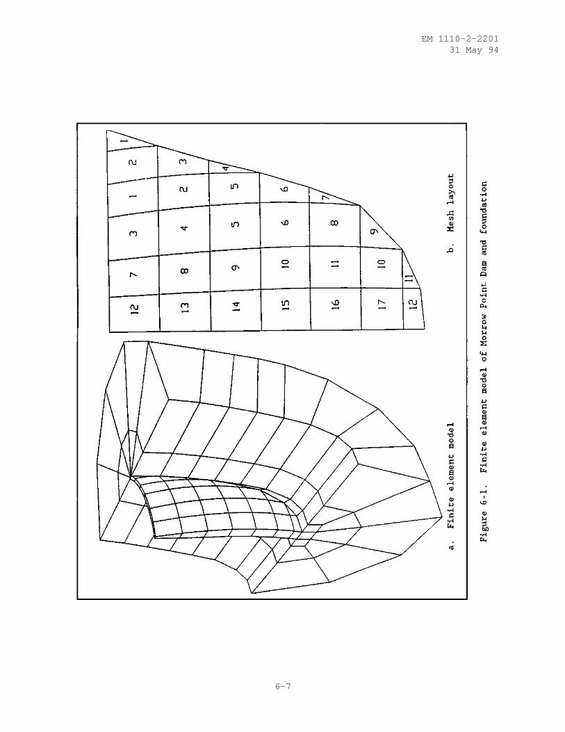
EM 1110-2-220131 May 94
6-7
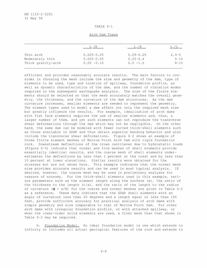
EM 1110-2-220131 May 94
TABLE 6-1
Arch Dam Types
______________________________________________________________________________t c /H t b /H t b /t c
Thin arch 0.025-0.05 0.09-0.25 2.9-5Moderately thin 0.025-0.05 0.25-0.4 5-10Thick gravity-arch 0.05 -0.10 0.5 -1.0 8-15______________________________________________________________________________
efficient and provides reasonably accurate results. The main factors to con-sider in choosing the mesh include the size and geometry of the dam, type ofelements to be used, type and location of spillway, foundation profile, aswell as dynamic characteristics of the dam, and the number of vibration modesrequired in the subsequent earthquake analysis. The size of the finite ele-ments should be selected so that the mesh accurately matches the overall geom-etry, the thickness, and the curvature of the dam structures. As the damcurvature increases, smaller elements are needed to represent the geometry.The element types used to model a dam affect not only the required mesh sizebut greatly influence the results. For example, idealization of arch damswith flat face elements requires the use of smaller elements and, thus, alarger number of them, and yet such elements can not reproduce the transverseshear deformations through the dam which may not be negligible. On the otherhand, the same dam can be modeled with fewer curved thick-shell elements suchas those available in GDAP and thus obtain superior bending behavior and alsoinclude the transverse shear deformations. Figure 6-2 shows an example ofthree finite element meshes of Morrow Point Arch Dam with rigid foundationrock. Downstream deflections of the crown cantilever due to hydrostatic loads(Figure 6-5) indicate that normal and fine meshes of shell elements provideessentially identical results, and the coarse mesh of shell elements under-estimates the deflections by less than 1 percent at the crest and by less than10 percent at lower elevations. Similar results were obtained for thestresses but are not shown here. This example indicates that the normal meshsize provides accurate results and can be used in most typical analysis. Ifdesired, however, the coarse mesh may be used in preliminary analyses forreasons of economy. For the thick-shell elements used in this example, vari-ous parameters such as the element length along the surface (a), the ratio ofthe thickness to the length (t/a), and the ratio of the length to the radiusof curvature ( φ = a/R) for the coarse and normal meshes are given in Table 6-2as a reference. These data indicate that the GDAP shell elements with anangle of curvature less than 20 degrees and a length equal or less than 150feet, provide sufficient accuracy for practical analysis of arch dams withsimple geometry and size comparable to that of Morrow Point Dam. For otherarch dams with irregular foundation profile, or with attached spillway, orwhen the lower-order solid elements are used, a finer mesh than that shown inTable 6-2 may be required.
b. Foundation Model. An ideal foundation model is one which extends toinfinity or includes all actual geological features of the rock and extends to
6-8
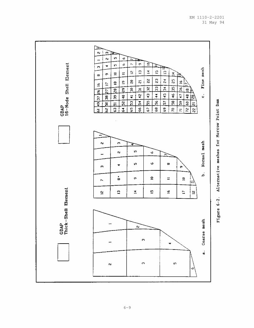
EM 1110-2-220131 May 94
6-9
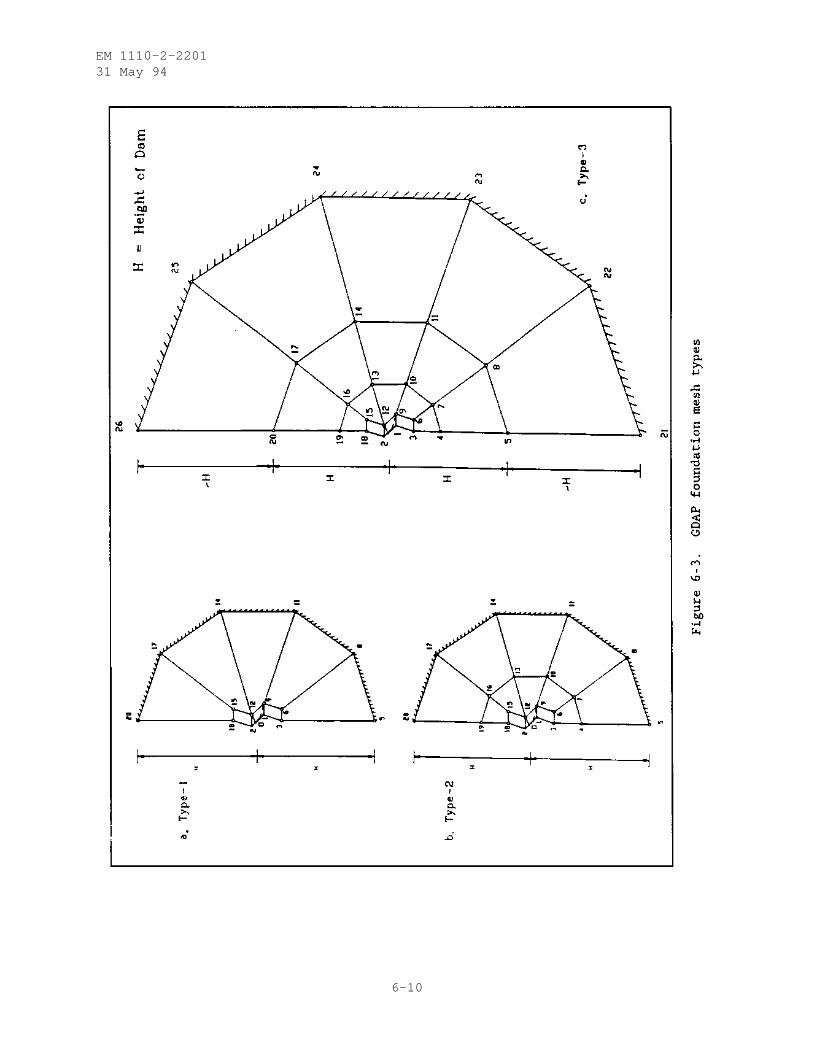
EM 1110-2-220131 May 94
6-10
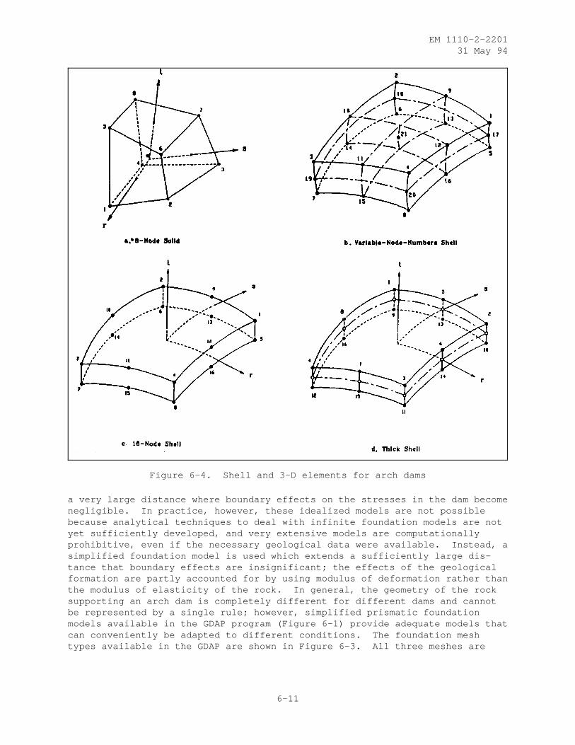
EM 1110-2-220131 May 94
Figure 6-4. Shell and 3-D elements for arch dams
a very large distance where boundary effects on the stresses in the dam becomenegligible. In practice, however, these idealized models are not possiblebecause analytical techniques to deal with infinite foundation models are notyet sufficiently developed, and very extensive models are computationallyprohibitive, even if the necessary geological data were available. Instead, asimplified foundation model is used which extends a sufficiently large dis-tance that boundary effects are insignificant; the effects of the geologicalformation are partly accounted for by using modulus of deformation rather thanthe modulus of elasticity of the rock. In general, the geometry of the rocksupporting an arch dam is completely different for different dams and cannotbe represented by a single rule; however, simplified prismatic foundationmodels available in the GDAP program (Figure 6-1) provide adequate models thatcan conveniently be adapted to different conditions. The foundation meshtypes available in the GDAP are shown in Figure 6-3. All three meshes are
6-11
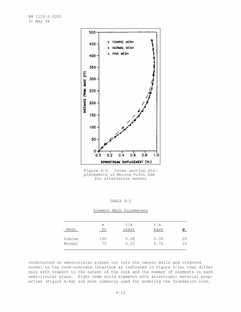
EM 1110-2-220131 May 94
Figure 6-5. Crown section dis-placements of Morrow Point Dam
for alternative meshes
TABLE 6-2
Element Mesh Parameters
____________________________________________________a t/a t/a
Mesh ft crest base φ
Coarse 150 0.08 0.34 20Normal 75 0.15 0.70 10____________________________________________________
constructed on semicircular planes cut into the canyon walls and orientednormal to the rock-concrete interface as indicated in Figure 6-1a; they differonly with respect to the extent of the rock and the number of elements in eachsemicircular plane. Eight-node solid elements with anisotropic material prop-erties (Figure 6-4a) are most commonly used for modeling the foundation rock.
6-12
EM 1110-2-220131 May 94
The foundation mesh is arranged so that smaller elements are located adjacentto the dam-foundation contact surface and the elements become larger towardthe boundaries of the model. The size of elements used near the interface iscontrolled by the dam thickness, and the size of the larger elements dependson the extent of foundation mesh and the number of elements to be used in eachsection.
(1) Effects of Foundation Deformability. The importance of foundationinteraction on the displacements and stresses resulting from loading an archdam has long been recognized. The results of a parametric study of MorrowPoint Dam, presented in Figures 6-6 through 6-8, demonstrate qualitatively therelative importance of the foundation modulus on the dam response. Threevalues of the rock modulus were considered: (a) rigid, (b) the same modulusas the concrete, and (c) one-fifth (1/5) the modulus of concrete. The analy-ses were made only for hydrostatic loads, and the effect of water load actingon the flexible foundation at the valley floor and on the flanks was alsoinvestigated. Figure 6-6 shows the deformation patterns while Figure 6-8compares the arch and cantilever stresses along the crown cantilever section.Deformations clearly are strongly affected by the rock modulus. The rotationof foundation rock, caused by the reservoir water, results in a slight rota-tion of the dam section in the upstream direction which is more pronounced forweaker rocks. Stresses also are considerably affected by foundation flexibil-ity as compared with the rigid foundation assumption and are further increasedby the weight of the impounded water which causes deformations of the founda-tion rock at the valley floor and flanks. It is important to realize thatactual foundations are seldom uniform and may have extensive weak zones. Insuch cases different values of rock modulus should be assigned to differentzones so that the variability effects may be assessed.
(2) Size of the Foundation-Rock Region. To account for the flexibilityeffects of the foundation rock, an appropriate volume of the foundation shouldbe included in the dam-foundation model to be analyzed; however, the amount offlexibility that is contributed by the foundation rock in actual field condi-tions has not been established. Larger foundation meshes can provide greaterflexibility; however, if more finite elements are used to subdivide thefoundation rock, greater data preparation and computational efforts arerequired. Moreover, the increased flexibility also can be obtained by using areduced foundation modulus. Therefore, the foundation idealization modelspresented in Figure 6-3 may be sufficient to select the minimum mesh extent(i.e., radius of semicircle R ƒ) which adequately represents the foundationflexibility effects. In static analysis, flexibility of foundation affectsdisplacements and stresses induced in the dam. For practical analysis, theminimum Rƒ is selected as a distance beyond which increasing R ƒ has negligibleeffects on the displacements and stresses in the dam. The static displace-ments along the crown cantilever of Morrow Point Dam for two concrete to rockmodulus ratios and for three foundation mesh types are shown in Figure 6-7.These results and the stress results (not shown here) suggest that foundationmesh type-1 is adequate for most practical analyses and especially for founda-tions in which the rock modulus is equal to or greater than the concretemodulus. For very flexible foundation rocks, however, mesh type-3 with an R ƒ
equal to two dam heights should be used.
6-13
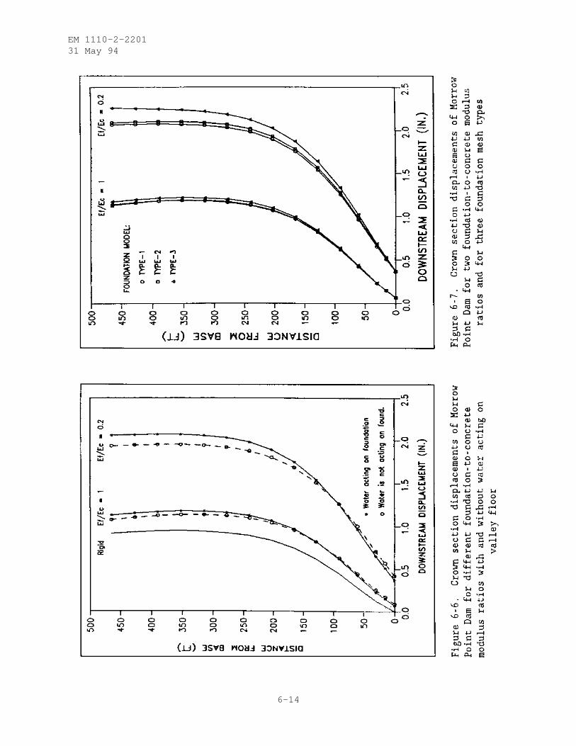
EM 1110-2-220131 May 94
6-14
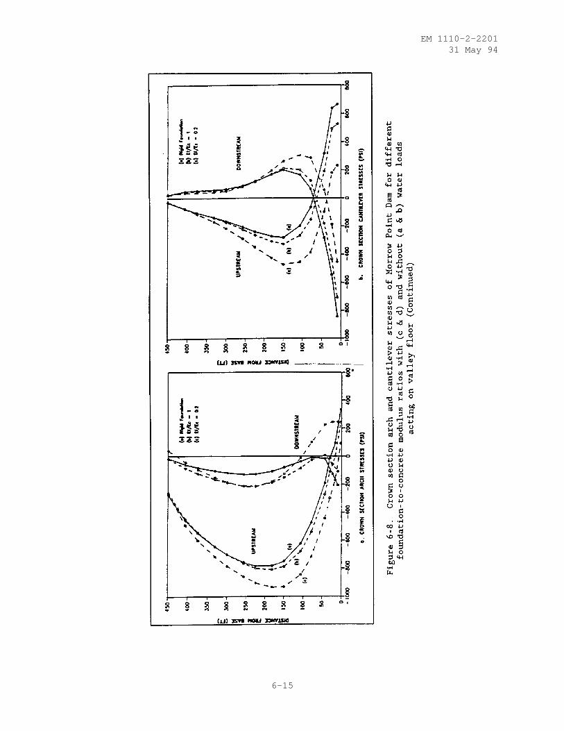
EM 1110-2-220131 May 94
6-15
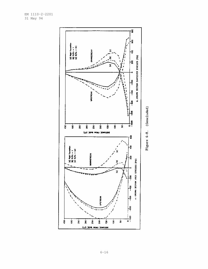
EM 1110-2-220131 May 94
6-16
EM 1110-2-220131 May 94
c. Appurtenant Structures. All modern dams include a number ofappurtenant structures and devices such as thrust blocks, spillways, gal-leries, and other openings. The effects of such appurtenances, if signifi-cant, should be considered in the analysis by including them in the finiteelement model of the dam structure.
(1) Thrust Blocks. Thrust blocks are often used as an artificial abut-ment where the foundation rock does not extend high enough to support thearches. Their main function is to resist the forces transmitted by the upperarches and transfer them to sound foundation rock at their base. They are acritical component of an arch dam design and should be included appropriatelyas part of the finite element model of the dam-foundation system. Thrustblocks may be adequately modeled using 8-node elements or any variation of8-to-20 node solid elements shown in Figures 6-4a and 6-4b. Several elementlayers are usually required to match the arch mesh at the junction and toaccount for excessive thickness of the thrust block.
(2) Spillways, Galleries, and Other Openings. Arch dams may bedesigned to accommodate spillways and various other openings such as gal-leries, sluiceways, and river outlets. Stresses usually tend to concentrateexcessively in the area of such openings, and care should be taken to reducetheir effects. The large cuts made at the crests of arch dams to provideopenings for overflow spillways should be included in the finite element modelof the dam structure in order to assess their effects on the stress distribu-tion. If necessary, the design of the dam should be modified to transfer loadaround the opening in the crest or to proportion the dam thickness to reducethe resulting stress concentrations. Spillways provided by tunnels or sidechannels that are independent of the arch dam are analyzed and designed sepa-rately; thus, they are not included in the finite element model of the dam.
(3) Other Openings Such as the Galleries, Sluiceways, and River Out-lets. These openings introduce a local disturbance in the prevalent stressfield and, in general, weaken the structure locally; however, the size ofthese openings usually does not have a significant influence on the overallstiffness of the dam structure, and their effect on the stress distributionmay be ignored if adequate reinforcing is provided to carry the forces aroundthe openings. Therefore, such openings need not be considered in the finiteelement mesh provided that the openings are small and adequately reinforced.
6-5. Presentation of Results. An important aspect of any finite elementanalysis is that of selecting and presenting essential information from theextensive results produced. It is extremely helpful to have the results pre-sented in graphical form, both for checking and evaluation purposes. Theresults should contain information for the complete structure to make a judge-ment regarding the dam safety, as well as to determine whether the boundarylocations are suitable or whether there are inconsistencies in the stressdistribution.
a. The basic results of a typical static analysis of an arch dam con-sist of nodal displacements and element stresses computed at various elementlocations. As a minimum, nodal displacements and surface stresses for thedesign load combinations specified in Chapter 4 should be presented. Addi-tional displacement and stress results due to the individual load pattern are
6-17
EM 1110-2-220131 May 94
also desirable because they provide basic information for interpretation ofthe indicated dam behavior.
b. Nodal displacements are computed in most computer analyses and aredirectly available. They are simply presented as deflected shapes acrossselected arches and cantilevers or for the entire dam structure in the form of3-D plots. However, consideration should be given to whether the displace-ments should be indicated in global (x,y) coordinates, or in terms of radialand tangential components for each surface node. The stresses usually arecomputed with respect to a global coordinate system but they should be trans-formed to surface arch, cantilever, and principal stress directions to sim-plify their interpretation. The arch and cantilever stress quantities usuallyare plotted as stress contours on each dam face, while the principal stresseson each face are presented in the form of vector plots as shown in Figure 6-9.In addition, plots of the arch and cantilever stresses determined across theupper arch section and along the cantilever sections are desirable for furtherdetailed study of the stresses.
6-6. Evaluation of Stress Results.
a. Evaluation of the stress results should start with careful examina-tion of the dam response to assure the validity of the computed results.Nodal displacements and stresses due to the individual loads are the mostappropriate data for this purpose. In particular, displacements and stressesacross the upper arch and the crown cantilever sections are extremely helpful.Such data are inspected for any unusual distributions and magnitudes thatcannot be explained by intuition and which differ significantly from theresults for similar arch dams. Once the accuracy of the analytical resultshas been accepted, the performance of the dam for the postulated loading com-binations must be evaluated.
b. This second stage of evaluation involves comparing the maximum cal-culated stresses with the specified strength of the concrete according to thecriteria established in Chapter 11. The analysis should include the effectsof all actual static loads that will act on the structure during the opera-tions, in accordance with the "Load Combinations" criteria presented in Chap-ter 4. The largest compressive and tensile stress for each load combinationcase should be less than the compressive and tensile strength of the concreteby the factors of safety specified for each design load combination. Whendesign criteria for all postulated loads are met and the factors of safety arein the acceptable range, the design is considered satisfactory, or, in thecase of an existing dam, it is considered safe under the static loads. How-ever, if calculated tensile stresses exceed the cracking strength of the con-crete or the lift joints or if tensile stresses are indicated across thevertical monolith joints, the possibility of tension cracking and joint open-ing must be considered and judgement is required to interpret the results.
(1) Under the static loads, a well designed arch dam should developessentially compressive stresses that are significantly less than the compres-sive strength of the concrete; however, tensile stresses may be developedunder multiple loading combinations, particularly when the temperature drop islarge and other conditions are unfavorable. Although unreinforced concretecan tolerate a limited amount of tensile stress, it is important to keep the
6-18
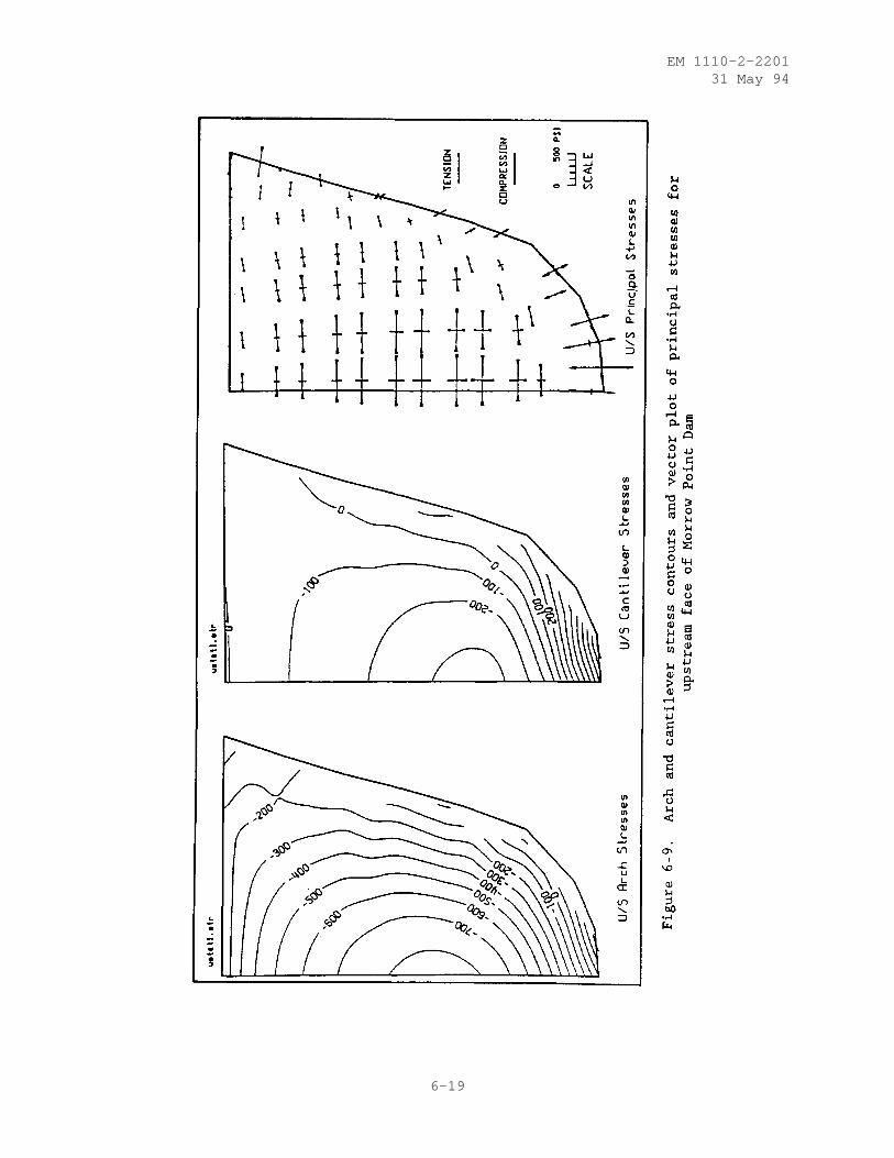
EM 1110-2-220131 May 94
6-19
EM 1110-2-220131 May 94
tension to a minimum so that the arch has sufficient reserve strength if sub-jected to additional seismic loads. Vertical (cantilever) tensile stressescan be minimized by vertical arching and overhanging of the crest, but theamount by which this can be done is limited by the stress and stability ofindividual cantilever blocks during the construction process. When the designlimits are reached or, as in the case of many existing dams, when the dam isnot designed for severe loading conditions, some cracking could occur at thebase and near the abutments. Linear-elastic analyses often indicate largestresses near the geometric discontinuity at the foundation contact. However,it is important to note that the tensile stresses indicated at the base of thearch dams by linear-elastic analyses are partly fictitious because these anal-yses do not take into account the limited bond between the concrete and foun-dation rock as well as the joints in the rock that could open when subjectedto tensile forces. In this situation, a more realistic estimate of staticstresses at the base of the dam may be obtained by a linear-elastic analysisthat uses a reduced foundation deformation modulus to decrease the tension inthe fractured rock.
(2) Arch dams rely significantly on arch action to transfer horizontalloads to the foundation. Therefore, in general, compressive arch stresses areexpected throughout the dam; however, the analyses of monolithic arch damswith empty reservoirs, with low water levels, or with severe low temperatureshave indicated that zones of horizontal tensile stresses can develop on theupstream and downstream dam faces. These tensile stresses combined with addi-tional tensile stresses due to temperature drop tend to open the verticalcontraction joints which are expected to have little or no tensile strength.It is apparent that joint opening will relieve any indicated arch tensilestresses, and the corresponding loads can be redistributed to cantileveraction provided that tensile arch stresses are limited to only a small portionof the dam.
(3) Shear stresses are rarely a problem in an arch dam; nevertheless,they should be checked to make sure that they remain within the allowablelimits.
c. In conclusion, the results of a linear elastic analysis are validonly if the cracking or joint openings that occur in the dam are minor and thetotal stiffness of the structure is not affected significantly. Therefore, itis necessary to evaluate the extent of cracking and to judge whether or not astate of no tension can safely be achieved in the dam and its foundation. Ifappreciable cracking is indicated, it is desirable to investigate its extentand its effects on actual stresses and deflections by analytical procedures.An approximate investigation based on a simplified nonlinear analysis may bemade by eliminating the tension areas by iteration and reanalyzing the arch.
6-20

EM 1110-2-220131 May 94
CHAPTER 7
EARTHQUAKE RESPONSE ANALYSIS
7-1. Introduction. A dynamic method of analysis is required to properlyassess the safety of existing concrete arch dams and to evaluate proposeddesigns for new dams that are located in regions with significant seismicity.Dynamic analysis is also performed to determine the adequacy of structuralmodifications proposed to improve the seismic performance of old dams. Theprediction of the actual dynamic response of arch dams to earthquake loadingsis a very complicated problem and depends on several factors including inten-sity and characteristics of the design earthquakes, interaction of the damwith the foundation rock and reservoir water, computer modeling, and the mate-rial properties used in the analysis. Detailed descriptions of the recom-mended dynamic analysis procedures are provided in the "Theoretical Manual forAnalysis of Arch Dams" (Ghanaat 1993b). Guidance concerning the seismic stud-ies needed to specify the design earthquake ground motions, methods of analy-sis, parameters influencing the dam response, and the presentation andevaluation of the analysis results are discussed in this chapter.
7-2. Geological-Seismological Investigation. Estimation of appropriate seis-mic excitation parameters is an important aspect of the seismic design, analy-sis, and evaluation of new and existing dams. Concrete arch dams built inseismic regions may be subjected to ground shaking due to an earthquake at thedam site or, more likely, to ground motions induced by distant earthquakes.In addition, large dams may experience earthquakes triggered at the dam siteimmediately following the reservoir impoundment or during a rapid drawdown.However, such reservoir-induced earthquakes are usually no greater than thoseto be expected without the reservoir, and they do not augment the seismicityof the region. The estimation of future earthquake ground motions at a damsite requires geological, seismological, geophysical, and geotechnical inves-tigations. The primary purposes of these studies are to establish thetectonic and geologic setting at and in the vicinity of the dam site, to iden-tify active faults and seismic sources, to collect and analyze the historicand instrumental seismic data, and to study the foundation conditions at thedam site that form the basis for estimating the ground motions. However, thelack of necessary data or difficulty in obtaining them, as well as numerousuncertainties associated with the source mechanism and the seismic wave propa-gation, often complicate the estimation process of ground motions. Therefore,at the present time seismic parameters for dam projects are approximated byempirical relations and through simplified procedures that decouple or neglectthe effects of less understood phenomena. The primary factors that must beconsidered in determination of the seismic parameters for dam projects arediscussed in the following paragraphs.
a. Regional Geologic Setting. A study of regional geology is requiredto understand the overall geologic setting and seismic history of a dam site.The study area, as a minimum, should cover a 100 km radius around the site.But in some cases it may be extended to as far as 300 km in order to includeall significant geologic features such as major faults and to account forarea-specific attenuation of earthquake ground motion with distance. A typi-cal geologic study consists of:
7-1

EM 1110-2-220131 May 94
(1) Description of the plate tectonic setting of the dam regiontogether with an account of recent movements.
(2) Regional geologic history and physiographic features.
(3) Description of geologic formations, rock types, soil deposits.
(4) Compilation of active faults in the site region and assessment ofthe capability of faults to generate earthquakes.
(5) Characterization of each capable fault in terms of its maximumexpected earthquake, recurrence intervals, total fault length, slip rate, sliphistory, and displacement per event, etc. Field work such as an exploratorytrench or bulldozer cuts may also be required to evaluate the seismic history.
b. Regional Seismicity. The seismic history of a region providesinformation on the occurrence of past earthquakes that help to identifyseismicity patterns and, thus, give an indication of what might be expected inthe future. Procedures for estimating the ground motion parameters at a par-ticular site are primarily based on historic and instrumentally recordedearthquakes and other pertinent geologic considerations. It is important,therefore, to carefully examine such information for accuracy, completenessand consistency. When possible, the following investigations may be required:
(1) Identification of seismic sources significant to the site, usuallywithin about a 200-km radius.
(2) Development of a catalog of the historical and instrumentallyrecorded earthquakes for the dam site region. The data, whenever possible,should include locations, magnitudes or epicentral intensity, date and time ofoccurrence, focal depth, and focal mechanism.
(3) Illustration of the compiled information by means of appropriateregional and local seismicity maps.
(4) Analysis of seismicity data to construct recurrence curves of thefrequency of earthquakes for the dam region, to examine spatial patterns ofepicenters for possible connection with the identified geologic structures,and to evaluate the catalog for completeness and accuracy.
(5) A review of the likelihood of reservoir induced seismicity (RIS) atthe dam site, although this is not expected to influence the design earthquakeparameters as previously mentioned.
c. Local Geologic Setting. Local geology should be studied to evaluatesome of the site-specific characteristics of the ground motion at the damsite. Such data include rock types, surface structures, local faults, shearsand joints, and the orientation and spacing of joint systems. In some cases,there may be geologic evidence of primary or sympathetic fault movementthrough the dam foundation. In those situations, a detailed geologic mapping,and geophysical and geotechnical exploration should be carried out to assessthe potential, amount, and the type of such movements at the dam site.
7-2
EM 1110-2-220131 May 94
7-3. Design Earthquakes. The geological and seismological investigationsdescribed in the previous paragraph provide the basis for estimating theearthquake ground motions to be used in the design and analysis of arch dams.The level of such earthquake ground motions depend on the seismic activity inthe dam site vicinity, source-to-site distance, length of potential faultruptures, source mechanism, surface geology of the dam site, and so on. Twoapproaches are available for estimating the ground motion parameters: deter-ministic and probabilistic. Both approaches require specification of seismicsources, assessing maximum magnitudes for each of the sources, and selectingground motion attenuation relationships. The probabilistic analysis requiresthe additional specification of the frequency of earthquake recurrence foreach of the sources in order to evaluate the likelihood of exceeding variouslevel of ground motion at the site. The earthquake ground motions for whicharch dams should be designed or analyzed include OBEs and MDEs. The groundmotions defined for each of these earthquakes are discussed in the followingparagraphs.
a. Operating Basis Earthquake (OBE). The OBE is defined as the groundmotion with a 50 percent probability of being exceeded in 100 years. Indesign and safety evaluation of arch dams, an OBE event should be consideredas an unusual loading condition as described in Chapter 4. The dam, itsappurtenant structures, and equipment should remain fully operational withminor or no damage when subjected to earthquake ground motions not exceedingthe OBE.
b. Maximum Design Earthquake (MDE). The MDE is the maximum level ofground motion for which the arch dam should be analyzed. The MDE is usuallyequated to the MCE which, by definition, is the largest reasonably possibleearthquake that could occur along a recognized fault or within a particularseismic source zone. In cases where the dam failure poses no danger to lifeor would not have severe economic consequences, an MDE less than the MCE maybe used for economic reasons. An MDE event should be considered as an extremeloading condition for which significant damage is acceptable, but without acatastrophic failure causing loss of life or severe economic loss.
c. Reservoir-induced Earthquake (RIE). The reservoir-induced earth-quake is the maximum level of ground motion that may be triggered at the damsite during filling, rapid drawdown, or immediately following the reservoirimpoundment. Statistical analysis of the presumed RIE cases have indicated arelation between the occurrence of RIE and the maximum water depth, reservoirvolume, stress regime, and local geology. The likelihood of an RIE is nor-mally considered for dams higher than about 250 feet and reservoirs withcapacity larger than about 10 5 acre-feet, but the possibility of an RIE occur-ring at new smaller dams located in tectonically sensitive areas should not beruled out. The possibility of RIE’s should therefore be considered whendesigning new high dams, even if the region shows low historical seismicity.The determination of whether the RIE should be considered as a dynamic unusualor a dynamic extreme loading condition (Table 4-2) should be based on theprobability of occurrence but recognizing that the RIE is no greater than theexpected earthquake if the reservoir had not been built.
7-4. Earthquake Ground Motions. The earthquake ground motions are character-ized in terms of peak ground acceleration, velocity, or displacement values,
7-3
EM 1110-2-220131 May 94
and seismic response spectra or acceleration time histories. For the evalua-tion of arch dams, the response spectrum and/or time-history representation ofearthquake ground motions should be used. The ground motion parameters forthe OBE are determined based on the probabilistic method. For the MCE, how-ever, they are normally estimated by deterministic analysis, but a probabil-istic analysis should also be considered so that the likelihood of a givenintensity of ground motion during the design life of the dam structure can bedetermined. The earthquake ground motions required as input for the seismicanalysis of arch dams are described in the following subparagraphs.
a. Design Response Spectra. The ground motion used for the seismicanalysis of arch dams generally is defined in the form of smooth responsespectra and the associated acceleration time histories. In most cases site-specific response spectra are required, except when the seismic hazard is verylow; in which case a generic spectral shape such as that provided in mostbuilding codes may suffice. When site-specific response spectra are required,the effects of magnitude, distance, and local geological conditions on theamplitude and frequency content of the ground motions should be considered.In general, the shape of the response spectrum for an OBE event is differentfrom that for the MCE, due to differences in the magnitude and the earthquakesources as shown in Figure 7-1. Thus, two separate sets of smooth responsespectra may be required, one for the OBE and another for the MCE. The smoothresponse spectra for each design earthquake should be developed for both hori-zontal and vertical components of the ground motion. The design spectra aretypically developed for 5 percent damping. Estimates for other damping valuescan be obtained using available relationships (Newmark and Hall 1982). Thevertical response spectra can be estimated using the simplified publishedrelationships between the vertical and horizontal spectra which will bedescribed in a future engineer manual. The relationship used should recognizethe significant influence of the source-to-site distance and of the particularperiod range ( ≤ 0.2 sec) on the vertical response spectra.
b. Acceleration Time Histories. When acceleration time histories ofground motions are used as seismic input for the dynamic analysis of archdams, they should be established with the design response spectra and shouldhave appropriate strong motion duration and number of peaks. The duration ofstrong motion is commonly measured by the bracketed duration. This is theduration of shaking between the first and last accelerations of the accelero-gram exceeding 0.05 g.
(1) Acceleration time histories are either selected from recordedground motions appropriate to the site, or they are synthetically developed ormodified from one or more ground motions. In the first approach, severalrecords are usually required to ensure that the response spectra of allrecords as a whole do not fall below the smooth design spectra. This proce-dure has the advantage that the dam is analyzed for natural motions, severaldynamic analyses should be performed. In addition, the response spectrum ofindividual records may have peaks that substantially exceed the designresponse spectra.
(2) Alternatively, acceleration time histories are developed either byartificially generating an accelerogram or by modifying a recorded accelero-gram so that the response spectrum of the resulting accelerogram closelymatches the design response spectra. The latter technique is preferred,
7-4
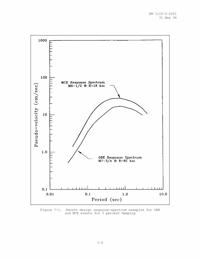
EM 1110-2-220131 May 94
Figure 7-1. Smooth design response-spectrum examples for OBEand MCE events for 5 percent damping
7-5
EM 1110-2-220131 May 94
because it starts with a natural accelerogram and thus preserves the durationand phasing of the original record and produces time histories that looknatural. An example of this procedure which shows a good match with thesmooth design response spectrum is demonstrated in Figure 7-2.
(3) For large thin arch dams with fundamental periods near 0.5 to 1 seclocated at close distances to the earthquake source, it is desirable toinclude a strong intermediate-to-long period pulse (0.5 to 5 sec) to accountfor the "fling" characteristic of near-source ground motion.
7-5. Finite Element Modeling Factors Affecting Dynamic Response. Dynamicanalysis of arch dams for earthquake loading should be based on a 3-D ideal-ization of the dam-water-foundation system which accounts for the significantinteraction effects of the foundation rock and the impounded water. To com-pute the linear response of the dam, the concrete arch and the foundation rockare modeled by standard finite elements, whereas the interaction effects ofthe impounded water can be represented with any of three different level ofrefinement. In addition, the dynamic response of arch dams is affected by thedamping and by the intensity and spatial variation of the seismic input.These factors and the finite element modeling of various components of an archdam are discussed in the following sections.
a. Arch Dam. The finite element model of an arch dam for dynamic anal-ysis is essentially identical to that developed for the static analysis. In alinear-elastic analysis, the arch dam is modeled as a monolithic structurewith no allowance for the probable contraction joint opening during earthquakeexcitation. Thin and moderately thin arch dams are adequately modeled by asingle layer of shell elements, whereas thick gravity-arch dams should berepresented by two or more layers of solid elements through the dam thickness.The size of the mesh should be selected following the general guidelines pre-sented in Chapter 6 for static analysis and shown in Figure 6-1. In addition,the dynamic response of the appurtenant structures attached to the dam may besignificant and also should be considered. For example, the power intakesattached to the dam may include free-standing cantilevers that could vibrateduring the earthquake shaking. The power intakes in this case should beincluded as part of the dam model to ensure that the dam stresses induced bythe vibration of these components are not excessive.
b. Dam-foundation Rock Interaction. Arch dams are designed to resistthe major part of the water pressures and other loads by transmitting themthrough arch action to the canyon walls. Consequently, the effects of foun-dation rock on the earthquake response of arch dams are expected to be signif-icant and must be considered in the dynamic analysis. However, a completesolution of the dam foundation interaction effects is very complicated andsuch procedures have not yet been fully developed. There are two major fac-tors contributing to this complex interaction problem. First is the lack of a3-D model of the unbounded foundation rock region to account for energy lossdue to the radiation of vibration waves. The other and even more importantcontributing factor is related to the prescription of spatial variation of theseismic input at the dam-foundation interface, resulting from wave propagationof seismic waves through the foundation rock and from scattering by the canyontopography. Faced with these difficulties, an overly simplified model of thefoundation rock (Clough 1980) is currently used in practice. This widely usedsimplified model ignores inertial and damping effects and considers only the
7-6
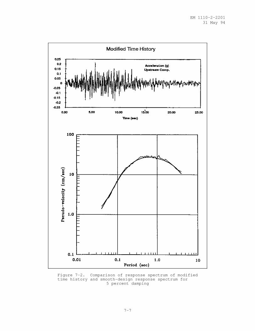
EM 1110-2-220131 May 94
Figure 7-2. Comparison of response spectrum of modifiedtime history and smooth-design response spectrum for
5 percent damping
7-7
EM 1110-2-220131 May 94
flexibility of the foundation rock. The foundation model for the dynamicanalysis is therefore similar to that described for the static analysis inChapter 6. As shown in Figures 6-1a and 6-3, an appropriate volume of thefoundation rock should be idealized by the finite element discretization ofthe rock region. Each foundation element is represented by a solid elementhaving eight or more nodes and characterized by its dynamic deformation modu-lus and Poisson’s ratio.
(1) Shape of Foundation Model. Using the finite element procedure, afoundation model can be developed to match the natural topography of the foun-dation rock region. However, such a refined model is usually not required inpractice. Instead, a prismatic model employed in the GDAP program anddescribed in Chapter 6 may be used. This foundation model depicted in Fig-ure 6-1a is constructed on semicircular planes cut into the canyon walls nor-mal to the dam-foundation contact surface; in moving from the base to the damcrest, each semicircle is rotated about a diameter always oriented in theupstream-downstream direction.
(2) Size of Foundation Model. The size of the foundation model consid-ered in GDAP is controlled by the radius (R f ) of the semicircular planesdescribed in the previous paragraph. In the static analysis discussed previ-ously, R f was selected so that the static displacements and stresses inducedin the dam were not changed by further increase of the foundation size. Inthe dynamic analysis, the natural frequencies and mode shapes of vibrationcontrol the dam response to earthquakes. Therefore, the size of a foundationmodel should be selected so that the static displacements and stresses, aswell as the natural frequencies and mode shapes, are accurately computed. Thenatural frequencies of the dam-foundation system decrease as the size of theflexible foundation rock increases (Clough et al. 1985 and Fok and Chopra1985), but for the massless foundation, the changes are negligible when thefoundation size R f is greater than one dam height, except for the foundationrocks with very low modulus of elasticity. For most practical purposes, amassless foundation model with R f equal to one dam height is adequate. How-ever, when the modulus ratio of the rock to concrete is less than one-half, amodel with R f equal to two times dam height should be used.
c. Dam-water Interaction. Interaction between the dam and impoundedwater is an important factor affecting the dynamic response of arch dams dur-ing earthquake ground shaking. In the simplest form, this interaction can berepresented by an "added mass" attached to the dam first formulated by Wester-gaard (1933). A more accurate representation of the added mass is obtainedusing a finite element formulation which accounts for the complicated geometryof the arch dam and the reservoir (Kuo 1982 (Aug)). Both approaches, however,ignore compressibility of water and the energy loss due to radiation of pres-sure waves in the upstream direction and due to reflection and refraction atthe reservoir bottom. These factors have been included in a recent and morerefined formulation (Fok and Chopra 1985 (July)), but computation of theresulting frequency-dependent hydrodynamic pressure terms requires extensiveefforts and requires consideration of a range of reservoir-bottom reflectioncoefficients.
(1) Generalized Westergaard Added Mass. Westergaard (1933) demon-strated that the effects of hydrodynamic pressures acting on the vertical faceof a rigid gravity dam could be represented by an added mass attached to the
7-8
EM 1110-2-220131 May 94
dam, if the compressibility of water is neglected. A general form of thisincompressible added-mass concept has been applied to the analysis of archdams (Kuo 1982 (Aug)). This generalized formulation, also described byGhanaat (1993b), is based on the same parabolic pressure distribution in thevertical direction used by Westergaard, but it recognizes the fact that thehydrodynamic pressures acting on the curved surface of an arch dam are due tothe total accelerations normal to the dam face. Although the resulting addedmass calculated in this manner is often used in the analysis of arch dams, itdoes not properly consider the hydrodynamic effects. In fact, there is norational basis for the assumed parabolic pressure distribution used for thearch dams, because limitations imposed in the original Westergaard formulationare violated. The original Westergaard formulation assumed a rigid dam with avertical upstream face and an infinite reservoir. However, the procedure isvery simple and provides a reasonable estimate of the hydrodynamic effects forpreliminary or feasibility analysis. The generalized added-mass formulationhas been implemented in the GDAP program and is available as an option. Theprogram automatically calculates the added mass for each nodal point on theupstream face of the dam; the resulting added mass of water is then added tothe mass of concrete to account for the hydrodynamic forces acting on the dam.
(2) Incompressible Finite Element Added Mass. In more refined analysesof new and existing arch dams, the effects of reservoir-water interaction dueto seismic loading is represented by an equivalent added mass of waterobtained from the hydrodynamic pressures acting on the face of the dam. Theprocedure is based on a finite element solution of the pressure wave equationsubjected to appropriate boundary conditions (Kuo 1982 (Aug) and Ghanaat(1993b)). The nodal point pressures of the incompressible water elements arethe unknowns. The bottom and sides of the reservoir, as well as a verticalplane at the upstream end, are assumed to be rigid. In addition, the hydrody-namic pressures at the water-free surface are set to zero; thus the effects ofsurface waves are neglected, but these have little effect on the seismicresponse. In general, a finite element model of the reservoir water can bedeveloped to match the natural canyon topography, but a prismatic reservoirmodel available in the GDAP program is quite adequate in most practical situa-tions. The GDAP reservoir model is represented by a cylindrical surface gen-erated by translating the dam-water interface nodes in the upstream directionas shown in Figure 7-3a. The resulting water nodes generated in this mannermatch those on the dam face and are usually arranged in successive planesparallel to the dam axis, with the distance between the planes increasing withdistance from the dam. Experience shows that the reservoir water shouldinclude at least three layers of elements that extend upstream a distance atleast three times the water depth.
(3) Compressible Water with Absorptive Reservoir Bottom. The added-mass representation of hydrodynamic effects ignores both water compressibilityeffects and the energy absorption mechanism at the reservoir bottom. Thesefactors have been included in a recent formulation of the dam-water interac-tion mechanism which is fully described by Fok and Chopra (1985 (July)). Itintroduces frequency-dependent hydrodynamic terms in the equations of motionthat can be interpreted as an added mass, an added damping, and an addedforce. The added damping term arises from the refraction of hydrodynamicpressure waves into the absorptive reservoir bottom and also from the propaga-tion of pressure waves in the upstream direction. The energy loss at thereservoir bottom is approximated by the wave reflection coefficient α, which
7-9
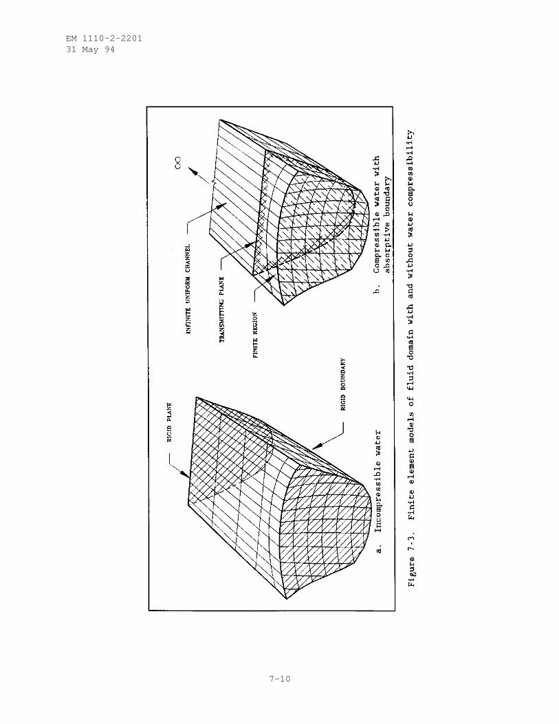
EM 1110-2-220131 May 94
7-10
EM 1110-2-220131 May 94
is defined as the ratio of reflected-to-incident wave amplitude of a pressurewave striking the reservoir bottom. The values of α can be varied from α =1.0, for a rigid, nonabsorptive boundary similar to that used in the GDAPmodel, to α = 0.0, indicating total absorption.
(a) The response analysis of an arch dam including the effects of dam-water interaction, water compressibility, and reservoir-bottom absorption canbe performed using the EACD-3D program (Fok, Hall, and Chopra 1986 (July)).The finite element idealizations of the dam and foundation rock employed inthis program are essentially equivalent to those employed by the GDAP program;the fluid region near the dam is modeled by liquid finite elements similar tothose in GDAP, but, unlike the GDAP, these elements are of compressible waterand are connected to a uniform channel extending to infinity to permit pres-sure waves to radiate away from the dam (Figure 7-3b).
(b) Another major difference of the EACD-3D model is that the reservoirboundary is absorptive and thus dissipation of hydrodynamic pressure waves inthe reservoir bottom materials is permitted. However, this method requiresconsiderable computational effort and is too complicated for most practicalapplications. An even more important consideration is the lack of guidance ormeasured data for determining an appropriate α factor for use in the analysis.Consequently, such analyses must be repeated for a range of α factors in orderto establish a lower and upper bound estimate of the dam response. It is alsoimportant to note that the significance of water compressibility depends onthe dynamic characteristics of the dam and the impounded water. Similar togravity dams (Chopra 1968), the effects of water compressibility for an archdam can be neglected if the ratio of the natural frequency of the reservoirwater to the natural frequency of the arch dam-foundation system without wateris greater than 2.
d. Damping. Damping has a significant effect on the response of anarch dam to earthquake and other dynamic loads. The energy loss arises fromseveral sources including the concrete arch structure, foundation rock, andthe reservoir water. Dissipation of energy in the concrete arch structure isdue to internal friction within the concrete material and at constructionjoints. In the foundation rock this energy loss is facilitated by propagationof elastic waves away from the dam (radiation damping) and by hystereticlosses due to sliding on cracks and fissures within the rock volume. An addi-tional source of damping, as discussed in paragraph 7-5c(3), is associatedwith the energy loss due to refraction of hydrodynamic pressure waves into thereservoir bottom materials and propagation of pressure waves in the upstreamdirection.
(1) The current standard earthquake analysis of arch dams is based on amassless foundation rock model and employs incompressible added mass forrepresenting the hydrodynamic effects. In this type of analysis, only thematerial damping associated with the concrete structure is explicitly consid-ered. The overall damping constant for the entire model in such linear-elastic analyses is normally specified based on the amplitude of the displace-ments, the opening of the vertical contraction joints, and the amount ofcracking that may occur in the concrete arch. Considering that the measureddamping values for concrete dams subjected to earthquake loading are scarceand that the effects of contraction joints, lift surfaces, and cracks cannot
7-11
EM 1110-2-220131 May 94
be precisely determined, the damping value for a moderate shaking such as anOBE event should be limited to 5 percent.
(2) However, under the MCE earthquake ground motions, damping constantsof 7 or 10 percent may be used depending on the level of strains developed inthe concrete and the amount of nonlinear joint opening and/or cracking thatoccurs. In more severe MCE conditions, especially for large dams, additionaldamping can be incorporated in the analysis by employing a dam-water inter-action model which includes water compressibility and permits for the dissipa-tion of energy at the reservoir boundary.
7-6. Method of Analysis. The current earthquake response analysis of archdams is based on linear-elastic dynamic analysis using the finite elementprocedures. It is assumed that the concrete dam and the interaction mecha-nisms with the foundation rock and the impounded water exhibit linear-elasticbehavior. Using this method, the arch dam and the foundation rock are treatedas 3-D systems idealized by the finite element discretization discussed inprevious paragraphs and in Chapter 6. Under the incompressible added-massassumption for the impounded water, the response analysis is performed usingthe response-spectrum modal-superposition or the time-history method. For thecase of compressible water, however, the response of the dam to dynamic loadsmust be evaluated using a frequency-domain procedure, in order to deal withthe frequency-dependent hydrodynamic terms. These methods of analyses arediscussed in the following paragraphs.
a. Response-spectrum Analysis. The response-spectrum method of analy-sis uses a response-spectrum representation of the seismic input motions tocompute the maximum response of an arch dam to earthquake loads. This approx-imate method provides an efficient procedure for the preliminary analyses ofnew and existing arch dams. It may also be used for the final analyses, ifthe calculated maximum stress values are sufficiently less than the allowablestresses of the concrete. Using this procedure, the maximum response of thearch dam is obtained by combining the maximum responses for each mode ofvibration computed separately.
(1) A complete description of the method is given in the theoreticalmanual by Ghanaat (1993b). First, the natural frequencies and mode shapes ofundamped free vibration for the combined dam-water-foundation system are eval-uated; the free vibration equations of motion are assembled considering themass of the dam-water system and the stiffness of the combined dam and founda-tion rock models. The maximum response in each mode of vibration is thenobtained from the specified response spectrum for each component of the groundmotion, using the modal damping and the natural period of vibration for eachparticular mode. The same damping constant is used in all modes as repre-sented by the response- spectrum curves. Since each mode reaches its maximumresponse at a different time, the total maximum response quantities for thedam, such as the nodal displacements and the element stresses, are approxi-mated by combining the modal responses using the square root of the sum of thesquares (SRSS) or complete quatratic combination (CQC) procedure. Finally,the resulting total maximum responses evaluated independently for each compo-nent of the earthquake ground motion are further combined by the SRSS methodfor the three earthquake input components, two horizontal and one vertical.
7-12
EM 1110-2-220131 May 94
(2) For a linear-elastic response, only a few lower modes of vibrationare needed to express the essential dynamic behavior of the dam structure.The appropriate number of vibration modes required in a particular analysisdepends on the dynamic characteristics of the dam structure and on the natureof earthquake ground motion. But, in all cases, a sufficient number of modesshould be included so that at least 90 percent of the "exact" dynamic responseis achieved. Since the "exact" response values are not known, a trial-and-error procedure may be adapted, or it may be demonstrated that the partici-pating effective modal masses are at least 90 percent of the total mass of thestructure.
b. Time-history Analysis. Time-history analysis should be performedwhen the maximum stress values computed by the response-spectrum method areapproaching or exceeding the tensile strength of the concrete. In these situ-ations, linear-elastic time-history analyses are performed to estimate themaximum stresses more accurately as well as to account for the time-dependentnature of the dynamic response. Time-history analyses provide not only themaximum stress values, but also the simultaneous, spatial extent and number ofexcursions beyond any specified stress value. Thus, they can indicate if thecalculated stresses beyond the allowable values are isolated incidents or ifthey occur repeatedly and over a significant area.
(1) The seismic input in time-history analyses is represented by theacceleration time histories of the earthquake ground motion. Three accelera-tion records corresponding to three components of the specified earthquake arerequired; they should be applied at the fixed boundaries of the foundationmodel in the channel, across the channel, and in the vertical directions. Theacceleration time histories are established following the procedures describedin paragraph 7-4b.
(2) The structural models of the dam, foundation rock, and theimpounded water for a time-history analysis are identical to those developedfor response-spectrum analysis. However, the solution to the equations ofmotion is obtained by a step-by-step numerical integration procedure. Twomethods of solution are available: direct integration and mode superposition(Ghanaat, technical report in preparation). In the direct method, step-by-step integration is applied to the original equations of motion with no trans-formation being carried out to uncouple them. Hence, this method requiresthat the damping matrix to be represented is in explicit form. In practice,this is accomplished using Raleigh damping (Clough and Penzien 1975), which isof the form
c a0 m a1 k
where coefficients a0 and a1 are obtained from two given damping ratios asso-ciated with two frequencies of vibration. The direct integration method ismost effective when the response is required for a relatively short duration.Otherwise, the mode superposition method in which the step-by-step integrationis applied to the uncoupled equations of motion will be more efficient. Inthe mode superposition method, first the undamped vibration mode shapes andfrequencies are calculated, and the equations of motion are transformed tothose coordinates. Then the response history for each mode is evaluated
7-13
EM 1110-2-220131 May 94
separately at each time-step, and the calculated modal response histories arecombined to obtain the total response of the dam structure. It should benoted that the damping in this case is expressed by the modal damping ratiosand need not be specified in explicit form.
7-7. Evaluation and Presentation of Results. The earthquake performance ofarch dams is currently evaluated using the numerical results obtained from alinear-dynamic analysis. The results of linear analysis provide a satisfac-tory estimate of the dynamic response to low- or moderate-intensity OBE earth-quake motions for which the resulting deformations of the dam are within thelinear-elastic range. In this case, the performance evaluation is based onsimple stress checks in which the calculated elastic stresses are comparedwith the specified strength of the concrete. Under the MCE ground motions, itis possible that the calculated stresses would exceed the allowable values andthat significant damage could occur. In such extreme cases, the dam shouldretain the impounded water without rupture, but the actual level of damage canbe estimated only by a nonlinear analysis that takes account of the basicnonlinear behavior mechanisms such as the joint opening, tensile cracking, andthe foundation failure. However, a complete nonlinear analysis is not cur-rently possible, and linear analysis continues to be the primary tool forassessing the seismic performance of arch dams subjected to damaging earth-quakes. Evaluation of the seismic performance for the MCE is more compli-cated, it requires some judgement and elaborate interpretations of the resultsbefore a reasonable estimate of the expected level of damage can be made orthe possibility of collapse can be assessed.
a. Evaluation of Response-spectrum Analysis. The first step inresponse spectrum analysis is the calculation of vibration mode shapes andfrequencies. The mode shapes and frequencies provide insight into the basicdynamic response behavior of an arch dam. They provide some advance indica-tion of the sensitivity of the dynamic response to earthquake ground motionshaving various frequency contents. Figure 7-4 demonstrates a convenient wayfor presenting the mode shapes. In this figure the vibration modes aredepicted as the plot of deflected shapes along the arch sections at variouselevations. After the calculation of mode shapes and frequencies, the maximumdynamic response of the dam structure is computed. These usually include themaximum nodal displacements and element stresses. In particular, the elementstresses are the primary response quantity used for the evaluation of earth-quake performance of the dam.
(1) Dynamic Response. The basic results of a response-spectrum analy-sis include the extreme values of the nodal displacements and element stressesdue to the earthquake loading. As discussed earlier, these extreme responsevalues are obtained by combining the maximum responses developed in each modeof vibration using the SRSS or CQC combination rule. In addition, they arefurther combined by the SRSS method to include the effects of all three compo-nents of the earthquake ground motion. Thus, the resulting dynamic responsevalues obtained in this manner have no sign and should be interpreted as beingeither positive or negative. For example the response-spectrum stress valuesare assumed to be either tension or compression.
(2) Total Response. The evaluation of earthquake performance of anarch dam using the response-spectrum method of analysis involves comparison ofthe total stresses due to both static and earthquake loads with the expected
7-14
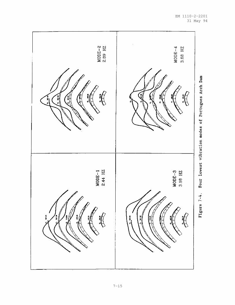
EM 1110-2-220131 May 94
7-15
EM 1110-2-220131 May 94
strength of the concrete. To obtain the total stress values, the response-spectrum estimate of the dynamic stresses ( σd) should be combined with theeffects of static loads ( σst ). The static stresses in a dam prior to theearthquake are computed using the procedures described in Chapter 6. Thestatic loads to be considered include the self-weight, hydrostatic pressures,and the temperature changes that are expected during the normal operatingcondition as discussed in Chapter 4. Since response-spectrum stresses have nosign, combination of static and dynamic stresses should consider dynamicstresses to be either positive or negative, leading to the maximum values oftotal tensile or compressive stresses:
σmax σst ± σd
(a) This combination of static and dynamic stresses is appropriate ifΣst and Σd are oriented similarly. This is true for arch or cantileverstresses at any point on the dam surface, but generally is not true for theprincipal stresses. In fact, it is not possible to calculate the principalstresses from a response-spectrum analysis, because the maximum arch and can-tilever stresses do not occur at the same time; therefore, they cannot be usedin the principal stress formulas.
(b) The computed total arch and cantilever stresses for the upstreamand downstream faces of the dam should be displayed in the form of stresscontours as shown in Figure 7-5. These represent the envelopes of maximumtotal arch and cantilever stresses on the faces of the dam, but because theyare not concurrent they cannot be combined to obtain envelopes of principalstresses, as was mentioned previously.
b. Results of Time-history Analysis. Time-history analysis computestime-dependent dynamic response of the dam model for the entire duration ofthe earthquake excitation. The results of such analyses provide not only themaximum response values, but also include time-dependent information thatmust be examined and interpreted systematically. Although evaluation of thedynamic response alone may sometimes be required, the final evaluation shouldbe based on the total response which also includes the effects of staticloads.
(1) Mode Shapes and Nodal Displacements. Vibration mode shapes andfrequencies are required when the mode-superposition method of time-historyanalysis is employed. But it is also a good practice to compute them for thedirect method. The computed vibration modes may be presented as shown inFigure 7-4 and discussed previously. The magnitude of nodal displacements anddeflected shape of an arch dam provide a visual means for the evaluation ofearthquake performance. As a minimum, displacement time histories for severalcritical nodal points should be displayed and evaluated. Figure 7-6 shows anexample of such displacement histories for a nodal point on the dam crest.
(2) Envelopes of Maximum and Minimum Arch and Cantilever Stresses.Examination of the stress results for a time-history analysis should startwith presentation of the maximum and minimum arch and cantilever stresses.These stresses should be displayed in the form of contour plots for theupstream and downstream faces of the dam. The contour plots of the maximum
7-16
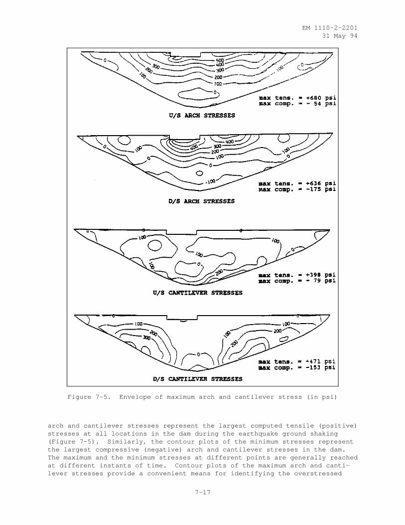
EM 1110-2-220131 May 94
Figure 7-5. Envelope of maximum arch and cantilever stress (in psi)
arch and cantilever stresses represent the largest computed tensile (positive)stresses at all locations in the dam during the earthquake ground shaking(Figure 7-5). Similarly, the contour plots of the minimum stresses representthe largest compressive (negative) arch and cantilever stresses in the dam.The maximum and the minimum stresses at different points are generally reachedat different instants of time. Contour plots of the maximum arch and canti-lever stresses provide a convenient means for identifying the overstressed
7-17
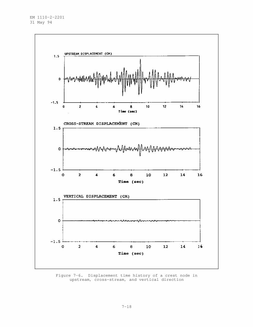
EM 1110-2-220131 May 94
Figure 7-6. Displacement time history of a crest node inupstream, cross-stream, and vertical direction
7-18
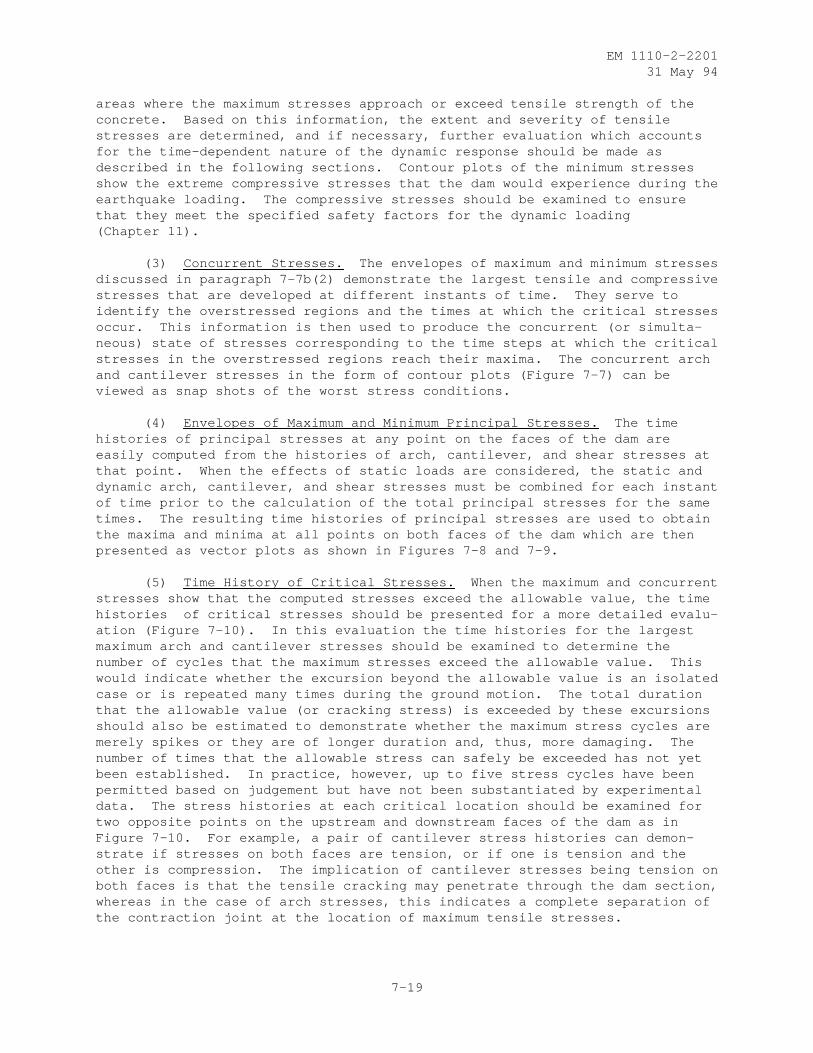
EM 1110-2-220131 May 94
areas where the maximum stresses approach or exceed tensile strength of theconcrete. Based on this information, the extent and severity of tensilestresses are determined, and if necessary, further evaluation which accountsfor the time-dependent nature of the dynamic response should be made asdescribed in the following sections. Contour plots of the minimum stressesshow the extreme compressive stresses that the dam would experience during theearthquake loading. The compressive stresses should be examined to ensurethat they meet the specified safety factors for the dynamic loading(Chapter 11).
(3) Concurrent Stresses. The envelopes of maximum and minimum stressesdiscussed in paragraph 7-7b(2) demonstrate the largest tensile and compressivestresses that are developed at different instants of time. They serve toidentify the overstressed regions and the times at which the critical stressesoccur. This information is then used to produce the concurrent (or simulta-neous) state of stresses corresponding to the time steps at which the criticalstresses in the overstressed regions reach their maxima. The concurrent archand cantilever stresses in the form of contour plots (Figure 7-7) can beviewed as snap shots of the worst stress conditions.
(4) Envelopes of Maximum and Minimum Principal Stresses. The timehistories of principal stresses at any point on the faces of the dam areeasily computed from the histories of arch, cantilever, and shear stresses atthat point. When the effects of static loads are considered, the static anddynamic arch, cantilever, and shear stresses must be combined for each instantof time prior to the calculation of the total principal stresses for the sametimes. The resulting time histories of principal stresses are used to obtainthe maxima and minima at all points on both faces of the dam which are thenpresented as vector plots as shown in Figures 7-8 and 7-9.
(5) Time History of Critical Stresses. When the maximum and concurrentstresses show that the computed stresses exceed the allowable value, the timehistories of critical stresses should be presented for a more detailed evalu-ation (Figure 7-10). In this evaluation the time histories for the largestmaximum arch and cantilever stresses should be examined to determine thenumber of cycles that the maximum stresses exceed the allowable value. Thiswould indicate whether the excursion beyond the allowable value is an isolatedcase or is repeated many times during the ground motion. The total durationthat the allowable value (or cracking stress) is exceeded by these excursionsshould also be estimated to demonstrate whether the maximum stress cycles aremerely spikes or they are of longer duration and, thus, more damaging. Thenumber of times that the allowable stress can safely be exceeded has not yetbeen established. In practice, however, up to five stress cycles have beenpermitted based on judgement but have not been substantiated by experimentaldata. The stress histories at each critical location should be examined fortwo opposite points on the upstream and downstream faces of the dam as inFigure 7-10. For example, a pair of cantilever stress histories can demon-strate if stresses on both faces are tension, or if one is tension and theother is compression. The implication of cantilever stresses being tension onboth faces is that the tensile cracking may penetrate through the dam section,whereas in the case of arch stresses, this indicates a complete separation ofthe contraction joint at the location of maximum tensile stresses.
7-19
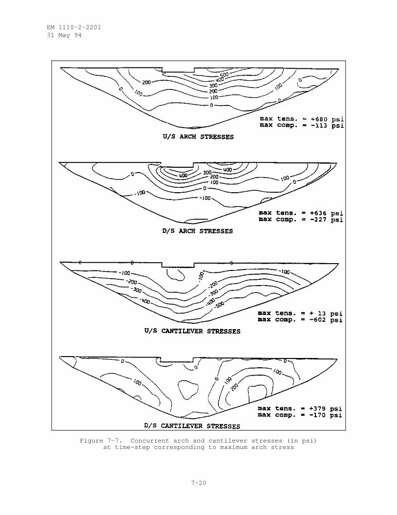
EM 1110-2-220131 May 94
Figure 7-7. Concurrent arch and cantilever stresses (in psi)at time-step corresponding to maximum arch stress
7-20
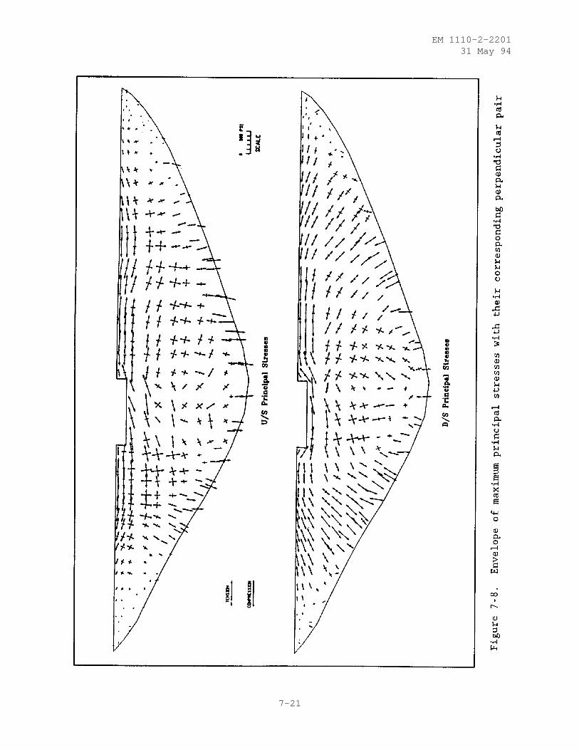
EM 1110-2-220131 May 94
7-21
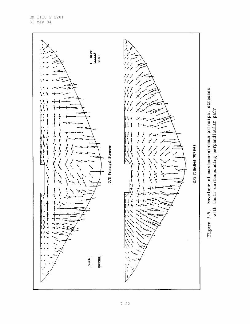
EM 1110-2-220131 May 94
7-22
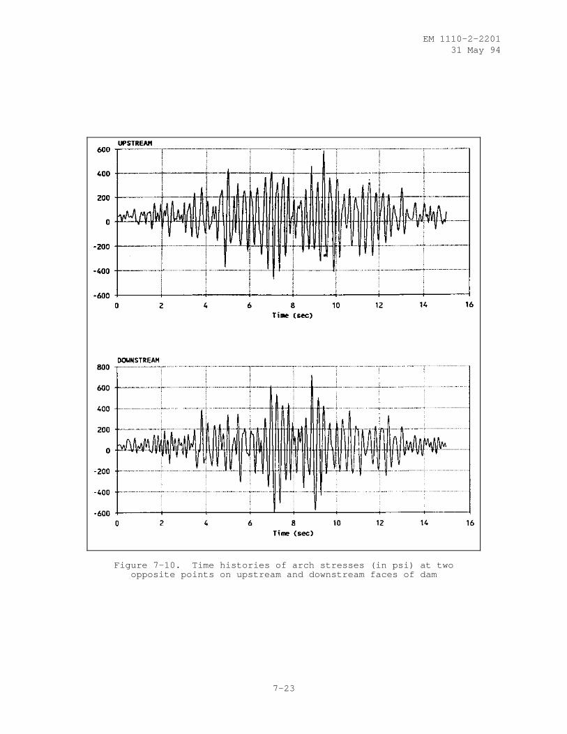
EM 1110-2-220131 May 94
Figure 7-10. Time histories of arch stresses (in psi) at twoopposite points on upstream and downstream faces of dam
7-23
EM 1110-2-220131 May 94
CHAPTER 8
TEMPERATURE STUDIES
8-1. Introduction. Temperature studies for arch dams fall into two distinctcategories. The first category is the operational temperature study which isused to determine the temperature loading in the dam. This study is performedearly in the design process. The second category includes the constructiontemperature studies which are usually performed after an acceptable layout hasbeen obtained. The construction temperature studies are needed to assure thatthe design closure temperature can be obtained while minimizing thepossibility of thermally induced cracking. The details of each of thesestudies are discussed in this chapter. Guidance is given on when the studiesshould be started, values that can be assumed prior to completion of thestudies, how to perform the studies, and what information is required to dothe studies.
8-2. Operational Temperature Studies.
a. General. The operational temperature studies are studies that areperformed to determine the temperature distributions that the dam will experi-ence during its expected life time. The shape of the temperature distributionthrough the thickness of the dam is, for the most part, controlled by thethickness of the structure. Dams with relatively thin sections will tend toexperience temperature distributions that approach a straight line from thereservoir temperature on the upstream face to the air temperature on the down-stream face as shown in Figure 8-1. Dams with a relatively thick section willexperience a somewhat different temperature distribution. The temperatures inthe center of a thick section will not respond as quickly to changes as tem-peratures at the faces. The temperatures in the center of the section willremain at or about the closure temperature, 1 with fluctuations of smallamplitude caused by varying environmental conditions. The concrete in closeproximity to the faces will respond quickly to the air and water temperaturechanges. Therefore, temperature distributions will result that are similar tothose shown in Figure 8-2.
(1) Before describing how these distributions can be obtained foranalysis, a description of how the temperatures are applied in the variousanalysis tools is appropriate. During the early design stages, when a damlayout is being determined, the trial load method is used. The computerizedversion of the trial load method which is widely used for the layout of thedam is the program ADSAS. ADSAS allows for temperatures to be applied in twoways. The first represents a uniform change in temperature from the grouttemperature. The second is a linear temperature load. This linear load canbe used to describe a straight line change in temperature from the upstream todownstream faces. These two methods can be used in combination to applychanges in temperature from the grout temperature as well as temperature
1 The terms grout temperature and closure temperature are often usedinterchangeably. They represent the concrete temperature condition at whichno temperature stress exists. This is also referred to as the stress-freetemperature condition.
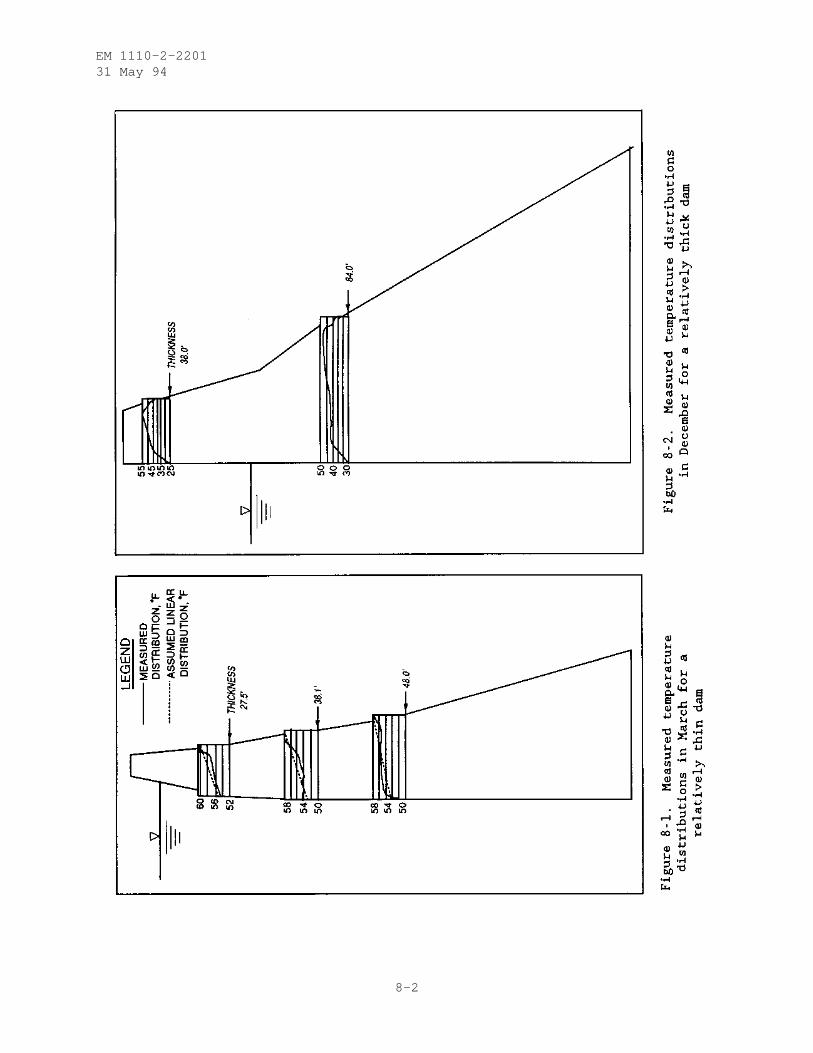
EM 1110-2-220131 May 94
8-2