Embed Size (px)
Citation preview
Signal DescriptionArc Welding Products
IRC5 M2004
3HEA 801231-001 Rev A
The information in this document is subject to alteration without prior notice and should not be regarded as an undertaking from ABB Automation Technologies AB. ABB Automation Technologies AB assumes no responsibility for errors that may occur in this document.
ABB Automation Technologies AB bears no responsibility for damage that is a consequence of using this document or the software or hardware described in this document.
The document, or parts of it, may not be reproduced or copied without prior permission from ABB Auto-mation Technologies AB. It may neither be imparted to a third party nor otherwise be used without autho-rization. Infringement hereof will be subject to action in accordance with applicable laws.
Further copies of this document can be obtained from ABB Automation Technologies AB at current prices.
© 2005 ABB Automation Technologies AB
ABB Automation Technologies ABRobotics & Manufacturing
SE-69582 LaxåSweden
3HEA 801231-001 Rev A i
Contents
Signal DescriptionArc Welding ProductsIRC5 M2004
1 General I/O Description 1
2 Process Interface 3
2.1 Arcitec/MigRob 42.1.1 I/O Board configuration 42.1.2 I/O Signals Configuration B_PROC_30 5
2.1.2.1 Digital outputs 52.1.2.2 Digital inputs 52.1.2.3 Analogue outputs 62.1.2.4 Analogue inputs 6
2.1.3 I/O Signals Configuration B_AW_PROC_40 72.1.3.1 Digital outputs 72.1.3.2 Digital inputs 72.1.3.3 Group outputs 72.1.3.4 Analogue inputs 7
2.1.4 I/O Signals Configuration B_AW_SIM 92.1.4.1 Digital output 9
2.2 ARCITEC/MigRob, Robot 2 102.2.1 I/O Board configuration 102.2.2 I/O Signals Configuration B_PROC_31 11
2.2.2.1 Digital outputs 112.2.2.2 Digital inputs 122.2.2.3 Analogue outputs 122.2.2.4 Analogue inputs 12
2.2.3 I/O Signals Configuration B_AW_PROC_41 132.2.3.1 Digital outputs 132.2.3.2 Digital inputs 132.2.3.3 Group outputs 132.2.3.4 Analogue inputs 14
2.2.4 I/O Signals Configuration B_AW_SIM 152.2.4.1 Digital output 15
2.3 RPB 162.3.1 I/O Board configuration 162.3.2 I/O Signals Configuration B_PROC_30 17
2.3.2.1 Digital outputs 172.3.2.2 Digital inputs 182.3.2.3 Analogue outputs 182.3.2.4 Analogue inputs 18
2.4 RPB, Robot 2 192.4.1 I/O Board configuration 192.4.2 I/O Signals Configuration B_PROC_31 20
2.4.2.1 Digital outputs 202.4.2.2 Digital inputs 212.4.2.3 Analogue outputs 21
ii 3HEA 801231-001 Rev A
2.4.2.4 Analogue inputs 21
2.5 Fronius 222.5.1 I/O Board configuration 222.5.2 I/O Signals Configuration FRON_BOARD_40 23
2.5.2.1 Digital outputs 232.5.2.2 Digital inputs 252.5.2.3 Analogue outputs 252.5.2.4 Group outputs 252.5.2.5 Group input 26
2.5.3 I/O Signals Configuration BOARD20 272.5.3.1 Digital outputs 272.5.3.2 Digital inputs 27
2.6 Fronius, Robot 2 282.6.1 I/O Board configuration 282.6.2 I/O Signals Configuration FRON_BOARD_41 29
2.6.2.1 Digital outputs 292.6.2.2 Digital inputs 302.6.2.3 Analogue outputs 312.6.2.4 Group outputs 312.6.2.5 Group input 31
2.6.3 I/O Signals Configuration BOARD20 322.6.3.1 Digital outputs 322.6.3.2 Digital inputs 32
3 Positioner Interface 33
3.1 IRBP A 343.1.1 I/O board Configuration for positioner 343.1.2 Simulated outputs for B_POS_SIM 35
3.1.2.1 Simulated outputs 353.1.2.2 Simulated inputs 35
3.1.3 I/O-Signals configuration for B_POS_21 363.1.3.1 Digital outputs TB4 363.1.3.2 Digital inputs TB3 36
3.1.4 Configuration cross-connections 37
3.2 IRBP B/D 383.2.1 I/O board Configuration for positioner 383.2.2 Simulated outputs for B_POS_SIM 39
3.2.2.1 Simulated outputs 393.2.2.2 Simulated inputs 39
3.2.3 I/O-Signals configuration for B_POS_21 403.2.3.1 Digital outputs TB4 403.2.3.2 Digital inputs TB3 40
3.2.4 Configuration cross-connections 41
3.3 IRBP C 423.3.1 I/O board Configuration for positioner 423.3.2 Simulated outputs for B_POS_SIM 43
3.3.2.1 Simulated outputs 43
3HEA 801231-001 Rev A iii
3.3.2.2 Simulated inputs 433.3.3 I/O-Signals configuration for B_POS_21 44
3.3.3.1 Digital outputs TB4 443.3.3.2 Digital inputs TB3 44
3.3.4 Configuration cross-connections 45
3.4 IRBP C Index 463.4.1 I/O board Configuration for positioner 463.4.2 Simulated outputs for B_POS_SIM 47
3.4.2.1 Simulated outputs 473.4.2.2 Simulated inputs 47
3.4.3 I/O-Signals configuration for B_POS_21 483.4.3.1 Digital outputs TB4 483.4.3.2 Digital inputs TB3 48
3.4.4 Configuration cross-connections 49
3.5 IRBP K/R 503.5.1 I/O board configuration for positioner 503.5.2 Simulated outputs for B_POS_SIM 51
3.5.2.1 Simulated outputs 513.5.2.2 Simulated inputs 51
3.5.3 I/O-Signals configuration for B_POS_21 523.5.3.1 Digital outputs TB4 523.5.3.2 Digital inputs TB3 52
3.5.4 Configuration cross-connections 533.5.4.1 K/R 3DU (3 axes) 533.5.4.2 K/R 1DU (1-axis) 54
3.6 IRBP L 553.6.1 I/O board configuration for positioner 553.6.2 Simulated outputs for B_POS_SIM 56
3.6.2.1 Simulated outputs 563.6.2.2 Simulated inputs 56
3.6.3 I/O-Signals configuration for B_POS_21 573.6.3.1 Digital outputs TB4 573.6.3.2 Digital inputs TB3 57
3.6.4 Configuration cross-connections 58
4 Operator Interface IRBP 59
4.1 I/O board Configuration 59
4.2 System functions 594.2.1 Inputs 594.2.2 Outputs 59
4.3 I/O-Signals configuration for B_OP_SIM 604.3.1 Digital outputs 60
4.4 I/O Signals configuration for USERIO 604.4.1 Digital outputs 604.4.2 Digital inputs 60
iv 3HEA 801231-001 Rev A
5 Safety interface SIB V 61
5.1 Positioner B/C/D/K/R 625.1.1 I/O board Configuration SIB V 625.1.2 I/O-signal configuration for SIB_V_B1 63
5.1.2.1 Digital inputs 635.1.2.2 Digital inputs 645.1.2.3 Configuration cross-connections 64
5.2 Positioner C Index 655.2.1 I/O board Configuration SIB V 655.2.2 I/O-signal configuration for SIB_V_B2 66
5.2.2.1 Digital inputs 665.2.2.2 Digital inputs 675.2.2.3 Configuration cross-connections 67
5.3 Positioner A/L/S 685.3.1 I/O board Configuration SIB V 685.3.2 I/O-signal configuration for SIB_V_B3 69
5.3.2.1 Digital inputs 695.3.2.2 Configuration cross-connections 71
General I/O Description
3HEA 801231-001 Rev A 1
1 General I/O Description
General
This description covers all signals in a standard Arc Welding System based on the standard process interface delivered byABB Automation Technology Products AB. By using the Arc Welding System Configuration diskette as a optional boot diskette, the I/O configuration for the selected process equipment, positioners and options will be installed.
Composition
There are four standard I/O-places inside the cabinet.The system interface is equipped with the following I/O units as standard:
• Simulated I/O Board
• Process Interface Board
• Digital I/O Board
• Software I/O Board
Unused I/O board places can be equipped with any I/O unit described in the Product Specification for the robot.
Usage
The number of I/O signals to be used is determined by different welding cell con-figurations:
• Welding equipment
• Positioner(s)
• Operator panel
• Cleaning equipment
• Search sensor
• Other options
To minimize the number of I/O units and signals, a simulated I/O board is used for some system signals and operator ready signals. The operator ready function is performed by using I/O cross connections with logical conditions.
General I/O Description
2 3HEA 801231-001 Rev A
System configuration
The complete I/O configuration for a specific system setup is obtained during the boot sequence. After boot-up, it is advisable to save the system configuration by making a back-up of the whole system. This shall be made in the service menu.
References
• Physical connections of I/O signals are shown in the electrical drawing for the signal interface (inside the robot control cubicle) in the System Manual.
• I/O units, CAN-bus connection and address keying are described in Installation and Commissioning in the "Connecting Signals" chapter in the Product Manual for the robot.
Electrical data, see Product Specification for the robot.
Note: Signals without any names in the following tables are not configured.
Process Interface
3HEA 801231-001 Rev A 3
2 Process Interface
General
This chapter describes the different standard process configurations delivered by ABB Automation Technologies AB.These configurations vary depending on which power source you have and whether you have Dualarc or not:
• For power source Arcitec or MigRob, see “Arcitec/MigRob” on page 4.
• For power source Arcitec or MigRob with Dualarc, see “Arcitec/MigRob” on page 4 for robot 1 and “ARCITEC/MigRob, Robot 2” on page 11 for robot 2.
• For power source RPB, see “RPB” on page 17.
• For power source RPB with Dualarc, see “RPB” on page 17 for robot 1 and “RPB, Robot 2” on page 21 for robot 2.
• For power source Fronius, see “Fronius” on page 25.
• For power source Fronius with Dualarc, see “Fronius” on page 25 for robot 1 and “Fronius, Robot 2” on page 31 for robot 2.
Process Interface
Arcitec/MigRob
4 3HEA 801231-001 Rev A
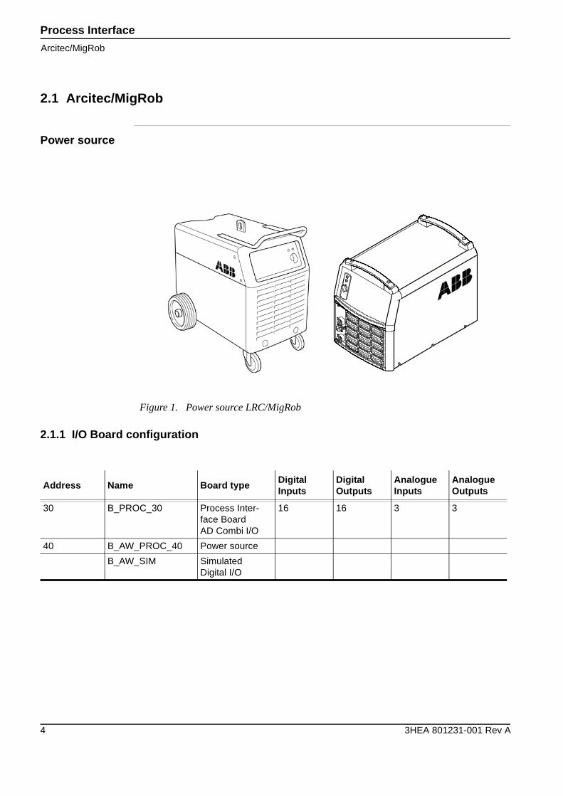
2.1 Arcitec/MigRob
Power source
2.1.1 I/O Board configuration
Figure 1. Power source LRC/MigRob
Address Name Board typeDigitalInputs
DigitalOutputs
AnalogueInputs
AnalogueOutputs
30 B_PROC_30 Process Inter-face BoardAD Combi I/O
16 16 3 3
40 B_AW_PROC_40 Power source
B_AW_SIM Simulated Digital I/O
Process InterfaceArcitec/MigRob
3HEA 801231-001 Rev A 5
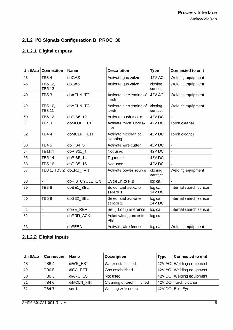
2.1.2 I/O Signals Configuration B_PROC_30
2.1.2.1 Digital outputs
2.1.2.2 Digital inputs
UnitMap Connection Name Description Type Connected to unit
48 TB5:4 doGAS Activate gas valve 42V AC Welding equipment
48 TB5:12, TB5:13
doGAS Activate gas valve closing contact
Welding equipment
49 TB5:3 doACLN_TCH Activate air cleaning of torch
42V AC Welding equipment
49 TB5:10, TB5:11
doACLN_TCH Activate air cleaning of torch
closing contact
Welding equipment
50 TB6:12 doPIB6_12 Activate push motor 42V DC -
51 TB4:3 doMLUB_TCH Activate torch lubrica-tion
42V DC Torch cleaner
52 TB4:4 doMCLN_TCH Activate mechanical cleaning
42V DC Torch cleaner
53 TB4:5 doPIB4_5 Activate wire cutter 42V DC -
54 TB11:4 doPIB11_4 Not used 42V DC -
55 TB5:14 doPIB5_14 Tig mode 42V DC -
56 TB5:16 doPIB5_16 Not used 42V DC -
57 TB3:1, TB3:2 doLRB_FAN Activate power source closing contact
Welding equipment
58 - doPIB_CYCLE_ON CycleOn to PIB logical -
59 TB5:6 doSE1_SEL Select and activate sensor 1
logical24V DC
Internal search sensor
60 TB5:9 doSE2_SEL Select and activate sensor 2
logical24V DC
Internal search sensor
61 - doSE_REF Set (=Lock) reference logical Internal search sensor
62 - doERR_ACK Acknowledge error in PIB
logical -
63 - doFEED Activate wire feeder logical Welding equipment
UnitMap Connection Name Description Type Connected to unit
48 TB6:4 diWR_EST Water established 42V AC Welding equipment
49 TB6:5 diGA_EST Gas established 42V AC Welding equipment
50 TB6:3 diARC_EST Not used 42V DC Welding equipment
51 TB4:6 diMCLN_FIN Cleaning of torch finished 42V DC Torch cleaner
52 TB4:7 sen1 Welding wire detect 42V DC BullsEye
Process Interface
Arcitec/MigRob
6 3HEA 801231-001 Rev A
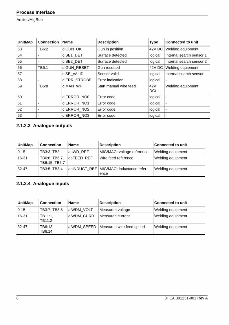
2.1.2.3 Analogue outputs
2.1.2.4 Analogue inputs
53 TB6:2 diGUN_OK Gun in position 42V DC Welding equipment
54 - diSE1_DET Surface detected logical Internal search sensor 1
55 - diSE2_DET Surface detected logical Internal search sensor 2
56 TB6:1 diGUN_RESET Gun resetted 42V DC Welding equipment
57 - diSE_VALID Sensor valid logical Internal search sensor
58 - diERR_STROBE Error indication logical -
59 TB6:8 diMAN_WF Start manual wire feed 42V DCt
Welding equipment
60 - diERROR_NO0 Error code logical -
61 - diERROR_NO1 Error code logical -
62 - diERROR_NO2 Error code logical -
63 - diERROR_NO3 Error code logical -
UnitMap Connection Name Description Type Connected to unit
UnitMap Connection Name Description Connected to unit
0-15 TB3:3, TB3 aoWD_REF MIG/MAG: voltage reference Welding equipment
16-31 TB6:6, TB6:7,TB6:15, TB6:7
aoFEED_REF Wire feed reference Welding equipment
32-47 TB3:5, TB3:4 aoINDUCT_REF MIG/MAG: inductance refer-ence
Welding equipment
UnitMap Connection Name Description Connected to unit
0-15 TB3:7, TB3:8 aiWDM_VOLT Measured voltage Welding equipment
16-31 TB11:1, TB11:2
aiWDM_CURR Measured current Welding equipment
32-47 TB6:13, TB6:14
aiWDM_SPEED Measured wire feed speed Welding equipment
Process InterfaceArcitec/MigRob
3HEA 801231-001 Rev A 7
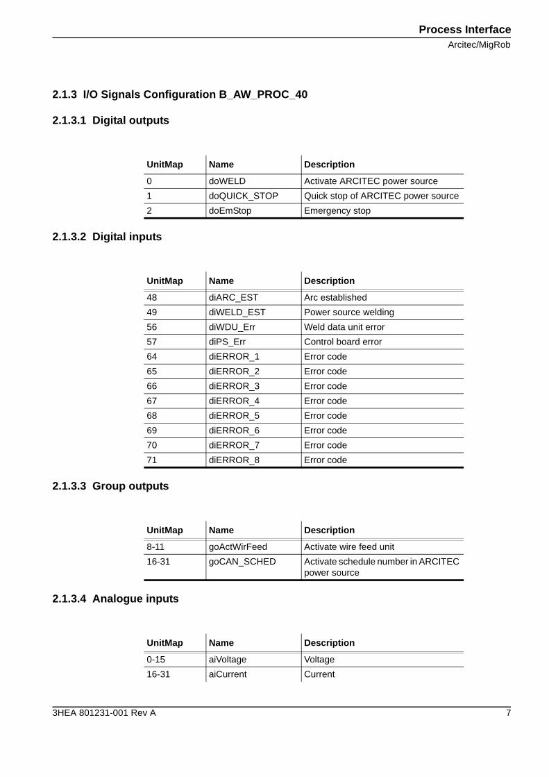
2.1.3 I/O Signals Configuration B_AW_PROC_40
2.1.3.1 Digital outputs
2.1.3.2 Digital inputs
2.1.3.3 Group outputs
2.1.3.4 Analogue inputs
UnitMap Name Description
0 doWELD Activate ARCITEC power source
1 doQUICK_STOP Quick stop of ARCITEC power source
2 doEmStop Emergency stop
UnitMap Name Description
48 diARC_EST Arc established
49 diWELD_EST Power source welding
56 diWDU_Err Weld data unit error
57 diPS_Err Control board error
64 diERROR_1 Error code
65 diERROR_2 Error code
66 diERROR_3 Error code
67 diERROR_4 Error code
68 diERROR_5 Error code
69 diERROR_6 Error code
70 diERROR_7 Error code
71 diERROR_8 Error code
UnitMap Name Description
8-11 goActWirFeed Activate wire feed unit
16-31 goCAN_SCHED Activate schedule number in ARCITEC power source
UnitMap Name Description
0-15 aiVoltage Voltage
16-31 aiCurrent Current
Process Interface
Arcitec/MigRob
8 3HEA 801231-001 Rev A
32-47 aiPower Power
UnitMap Name Description
Process InterfaceArcitec/MigRob
3HEA 801231-001 Rev A 9
2.1.4 I/O Signals Configuration B_AW_SIM
2.1.4.1 Digital output
UnitMap Name Description
doFEED_SIM Activate wire feed
Process Interface
ARCITEC/MigRob, Robot 2
10 3HEA 801231-001 Rev A
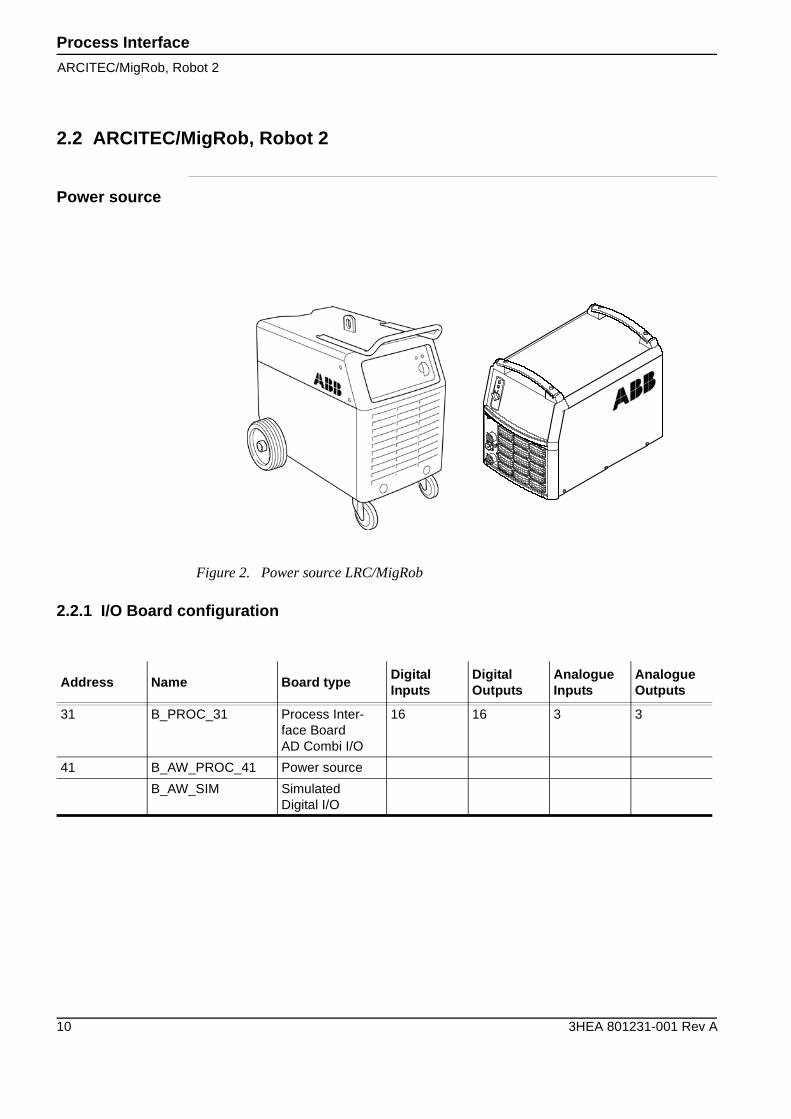
2.2 ARCITEC/MigRob, Robot 2
Power source
2.2.1 I/O Board configuration
Figure 2. Power source LRC/MigRob
Address Name Board typeDigitalInputs
DigitalOutputs
AnalogueInputs
AnalogueOutputs
31 B_PROC_31 Process Inter-face BoardAD Combi I/O
16 16 3 3
41 B_AW_PROC_41 Power source
B_AW_SIM Simulated Digital I/O
Process InterfaceARCITEC/MigRob, Robot 2
3HEA 801231-001 Rev A 11
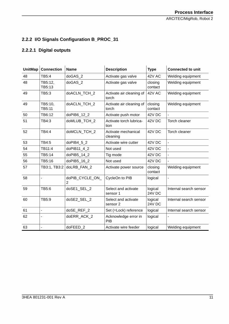
2.2.2 I/O Signals Configuration B_PROC_31
2.2.2.1 Digital outputs
UnitMap Connection Name Description Type Connected to unit
48 TB5:4 doGAS_2 Activate gas valve 42V AC Welding equipment
48 TB5:12, TB5:13
doGAS_2 Activate gas valve closing contact
Welding equipment
49 TB5:3 doACLN_TCH_2 Activate air cleaning of torch
42V AC Welding equipment
49 TB5:10, TB5:11
doACLN_TCH_2 Activate air cleaning of torch
closing contact
Welding equipment
50 TB6:12 doPIB6_12_2 Activate push motor 42V DC -
51 TB4:3 doMLUB_TCH_2 Activate torch lubrica-tion
42V DC Torch cleaner
52 TB4:4 doMCLN_TCH_2 Activate mechanical cleaning
42V DC Torch cleaner
53 TB4:5 doPIB4_5_2 Activate wire cutter 42V DC -
54 TB11:4 doPIB11_4_2 Not used 42V DC -
55 TB5:14 doPIB5_14_2 Tig mode 42V DC -
56 TB5:16 doPIB5_16_2 Not used 42V DC -
57 TB3:1, TB3:2 doLRB_FAN_2 Activate power source closing contact
Welding equipment
58 - doPIB_CYCLE_ON_2
CycleOn to PIB logical -
59 TB5:6 doSE1_SEL_2 Select and activate sensor 1
logical24V DC
Internal search sensor
60 TB5:9 doSE2_SEL_2 Select and activate sensor 2
logical24V DC
Internal search sensor
61 - doSE_REF_2 Set (=Lock) reference logical Internal search sensor
62 - doERR_ACK_2 Acknowledge error in PIB
logical -
63 - doFEED_2 Activate wire feeder logical Welding equipment
Process Interface
ARCITEC/MigRob, Robot 2
12 3HEA 801231-001 Rev A
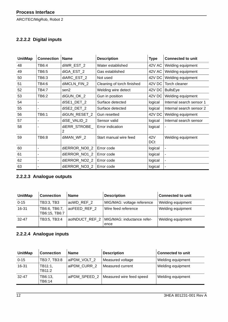
2.2.2.2 Digital inputs
2.2.2.3 Analogue outputs
2.2.2.4 Analogue inputs
UnitMap Connection Name Description Type Connected to unit
48 TB6:4 diWR_EST_2 Water established 42V AC Welding equipment
49 TB6:5 diGA_EST_2 Gas established 42V AC Welding equipment
50 TB6:3 diARC_EST_2 Not used 42V DC Welding equipment
51 TB4:6 diMCLN_FIN_2 Cleaning of torch finished 42V DC Torch cleaner
52 TB4:7 sen2 Welding wire detect 42V DC BullsEye
53 TB6:2 diGUN_OK_2 Gun in position 42V DC Welding equipment
54 - diSE1_DET_2 Surface detected logical Internal search sensor 1
55 - diSE2_DET_2 Surface detected logical Internal search sensor 2
56 TB6:1 diGUN_RESET_2 Gun resetted 42V DC Welding equipment
57 - diSE_VALID_2 Sensor valid logical Internal search sensor
58 - diERR_STROBE_2
Error indication logical -
59 TB6:8 diMAN_WF_2 Start manual wire feed 42V DCt
Welding equipment
60 - diERROR_NO0_2 Error code logical -
61 - diERROR_NO1_2 Error code logical -
62 - diERROR_NO2_2 Error code logical -
63 - diERROR_NO3_2 Error code logical -
UnitMap Connection Name Description Connected to unit
0-15 TB3:3, TB3 aoWD_REF_2 MIG/MAG: voltage reference Welding equipment
16-31 TB6:6, TB6:7,TB6:15, TB6:7
aoFEED_REF_2 Wire feed reference Welding equipment
32-47 TB3:5, TB3:4 aoINDUCT_REF_2 MIG/MAG: inductance refer-ence
Welding equipment
UnitMap Connection Name Description Connected to unit
0-15 TB3:7, TB3:8 aiPDM_VOLT_2 Measured voltage Welding equipment
16-31 TB11:1, TB11:2
aiPDM_CURR_2 Measured current Welding equipment
32-47 TB6:13, TB6:14
aiPDM_SPEED_2 Measured wire feed speed Welding equipment
Process InterfaceARCITEC/MigRob, Robot 2
3HEA 801231-001 Rev A 13
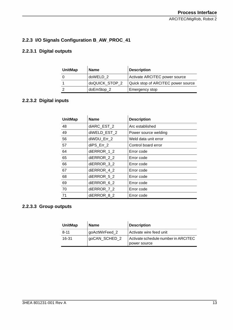
2.2.3 I/O Signals Configuration B_AW_PROC_41
2.2.3.1 Digital outputs
2.2.3.2 Digital inputs
2.2.3.3 Group outputs
UnitMap Name Description
0 doWELD_2 Activate ARCITEC power source
1 doQUICK_STOP_2 Quick stop of ARCITEC power source
2 doEmStop_2 Emergency stop
UnitMap Name Description
48 diARC_EST_2 Arc established
49 diWELD_EST_2 Power source welding
56 diWDU_Err_2 Weld data unit error
57 diPS_Err_2 Control board error
64 diERROR_1_2 Error code
65 diERROR_2_2 Error code
66 diERROR_3_2 Error code
67 diERROR_4_2 Error code
68 diERROR_5_2 Error code
69 diERROR_6_2 Error code
70 diERROR_7_2 Error code
71 diERROR_8_2 Error code
UnitMap Name Description
8-11 goActWirFeed_2 Activate wire feed unit
16-31 goCAN_SCHED_2 Activate schedule number in ARCITEC power source
Process Interface
ARCITEC/MigRob, Robot 2
14 3HEA 801231-001 Rev A
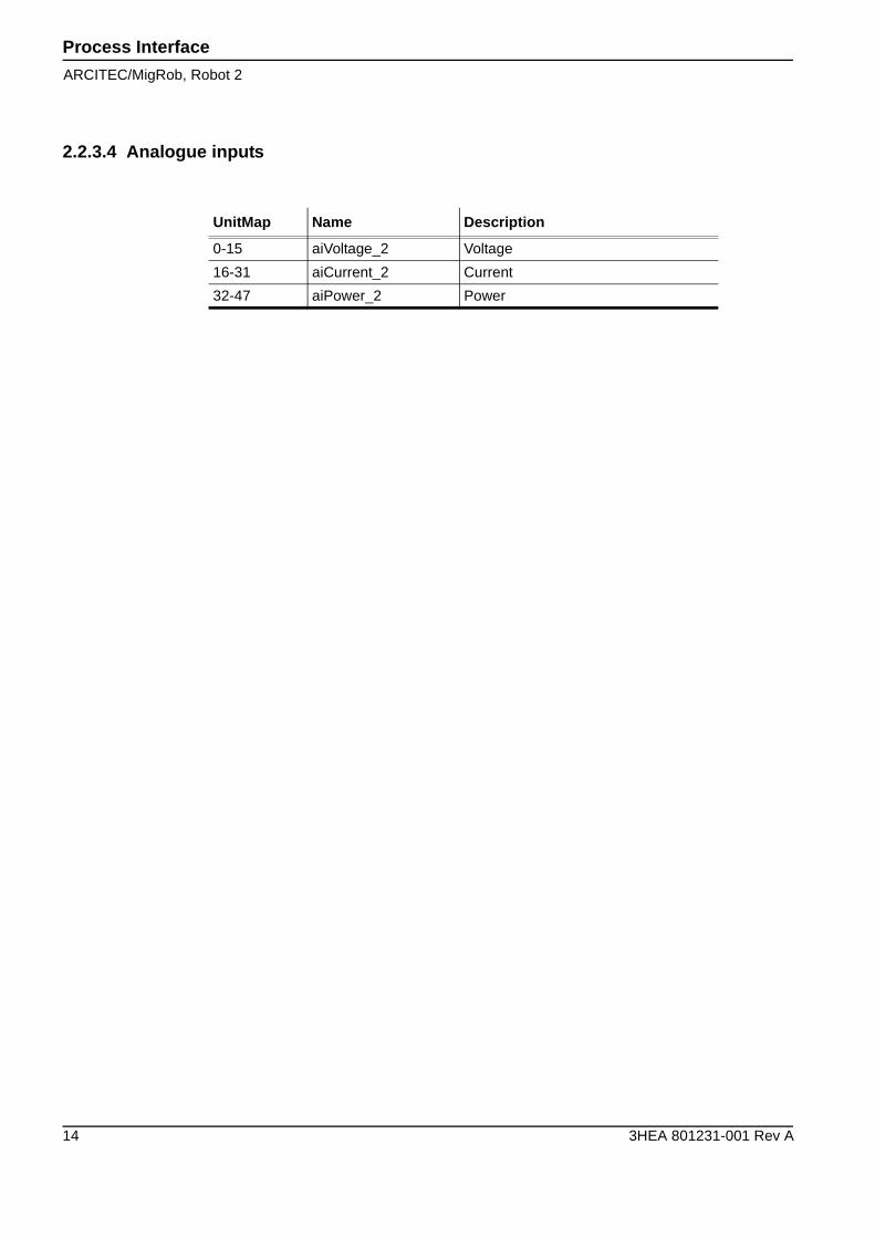
2.2.3.4 Analogue inputs
UnitMap Name Description
0-15 aiVoltage_2 Voltage
16-31 aiCurrent_2 Current
32-47 aiPower_2 Power
Process InterfaceARCITEC/MigRob, Robot 2
3HEA 801231-001 Rev A 15
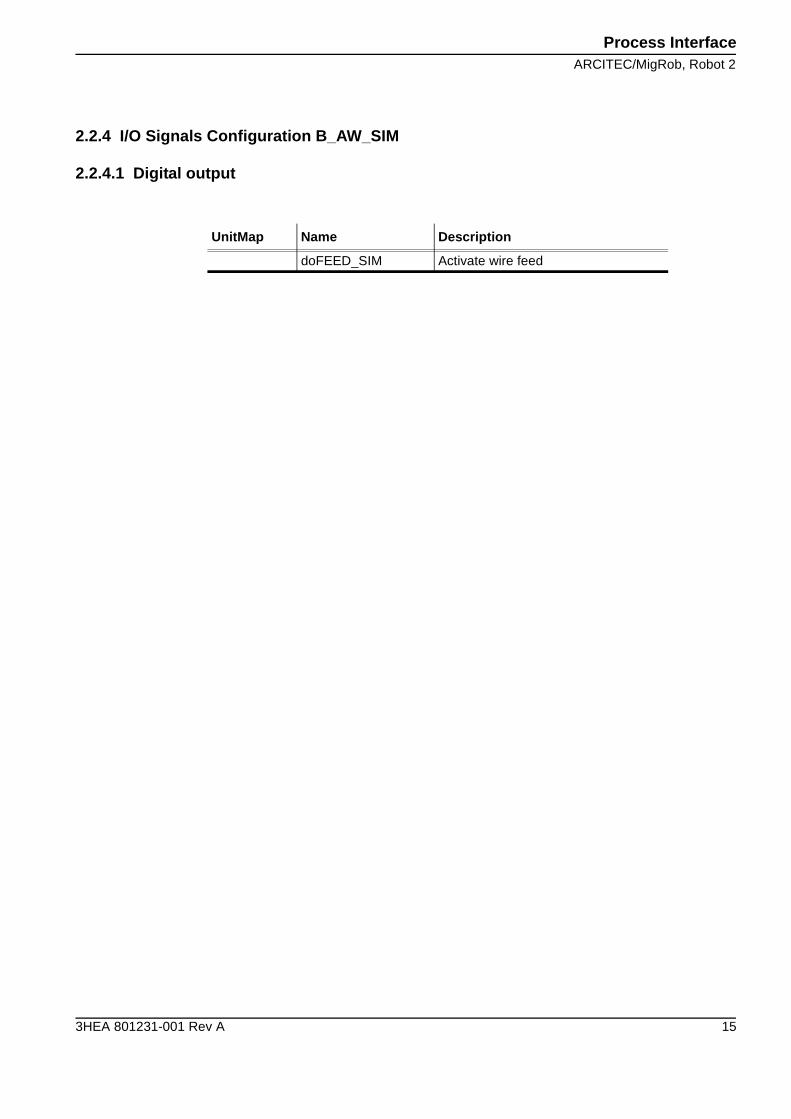
2.2.4 I/O Signals Configuration B_AW_SIM
2.2.4.1 Digital output
UnitMap Name Description
doFEED_SIM Activate wire feed
Process Interface
RPB
16 3HEA 801231-001 Rev A
2.3 RPB
Power source
2.3.1 I/O Board configuration
Figure 3. Power source RPB
Address Name Board typeDigitalInputs
DigitalOutputs
AnalogueInputs
AnalogueOutputs
30 B_PROC_30 Process Inter-face Board
16 16 3 3
Process InterfaceRPB
3HEA 801231-001 Rev A 17
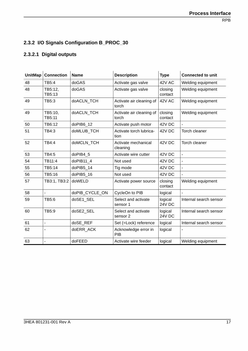
2.3.2 I/O Signals Configuration B_PROC_30
2.3.2.1 Digital outputs
UnitMap Connection Name Description Type Connected to unit
48 TB5:4 doGAS Activate gas valve 42V AC Welding equipment
48 TB5:12, TB5:13
doGAS Activate gas valve closing contact
Welding equipment
49 TB5:3 doACLN_TCH Activate air cleaning of torch
42V AC Welding equipment
49 TB5:10, TB5:11
doACLN_TCH Activate air cleaning of torch
closing contact
Welding equipment
50 TB6:12 doPIB6_12 Activate push motor 42V DC -
51 TB4:3 doMLUB_TCH Activate torch lubrica-tion
42V DC Torch cleaner
52 TB4:4 doMCLN_TCH Activate mechanical cleaning
42V DC Torch cleaner
53 TB4:5 doPIB4_5 Activate wire cutter 42V DC -
54 TB11:4 doPIB11_4 Not used 42V DC -
55 TB5:14 doPIB5_14 Tig mode 42V DC -
56 TB5:16 doPIB5_16 Not used 42V DC -
57 TB3:1, TB3:2 doWELD Activate power source closing contact
Welding equipment
58 - doPIB_CYCLE_ON CycleOn to PIB logical -
59 TB5:6 doSE1_SEL Select and activate sensor 1
logical24V DC
Internal search sensor
60 TB5:9 doSE2_SEL Select and activate sensor 2
logical24V DC
Internal search sensor
61 - doSE_REF Set (=Lock) reference logical Internal search sensor
62 - doERR_ACK Acknowledge error in PIB
logical -
63 - doFEED Activate wire feeder logical Welding equipment
Process Interface
RPB
18 3HEA 801231-001 Rev A
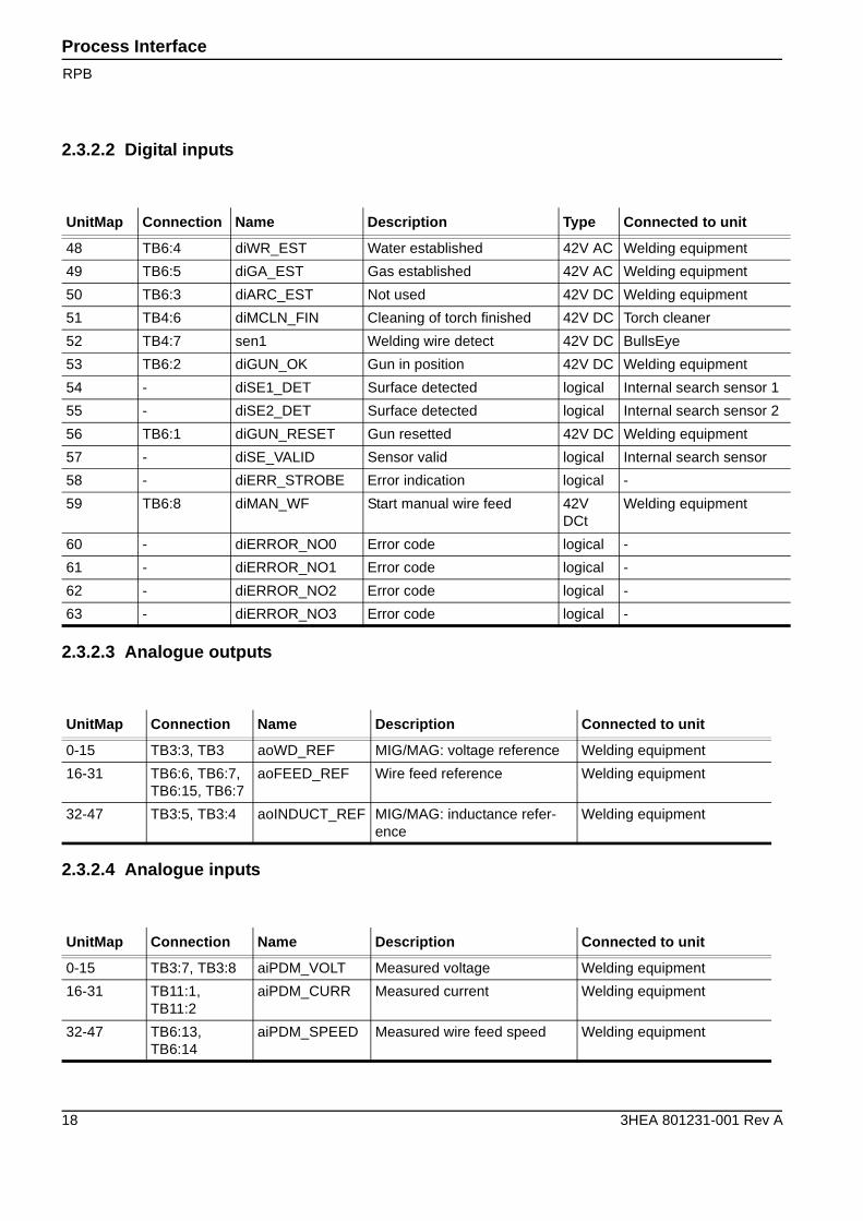
2.3.2.2 Digital inputs
2.3.2.3 Analogue outputs
2.3.2.4 Analogue inputs
UnitMap Connection Name Description Type Connected to unit
48 TB6:4 diWR_EST Water established 42V AC Welding equipment
49 TB6:5 diGA_EST Gas established 42V AC Welding equipment
50 TB6:3 diARC_EST Not used 42V DC Welding equipment
51 TB4:6 diMCLN_FIN Cleaning of torch finished 42V DC Torch cleaner
52 TB4:7 sen1 Welding wire detect 42V DC BullsEye
53 TB6:2 diGUN_OK Gun in position 42V DC Welding equipment
54 - diSE1_DET Surface detected logical Internal search sensor 1
55 - diSE2_DET Surface detected logical Internal search sensor 2
56 TB6:1 diGUN_RESET Gun resetted 42V DC Welding equipment
57 - diSE_VALID Sensor valid logical Internal search sensor
58 - diERR_STROBE Error indication logical -
59 TB6:8 diMAN_WF Start manual wire feed 42V DCt
Welding equipment
60 - diERROR_NO0 Error code logical -
61 - diERROR_NO1 Error code logical -
62 - diERROR_NO2 Error code logical -
63 - diERROR_NO3 Error code logical -
UnitMap Connection Name Description Connected to unit
0-15 TB3:3, TB3 aoWD_REF MIG/MAG: voltage reference Welding equipment
16-31 TB6:6, TB6:7,TB6:15, TB6:7
aoFEED_REF Wire feed reference Welding equipment
32-47 TB3:5, TB3:4 aoINDUCT_REF MIG/MAG: inductance refer-ence
Welding equipment
UnitMap Connection Name Description Connected to unit
0-15 TB3:7, TB3:8 aiPDM_VOLT Measured voltage Welding equipment
16-31 TB11:1, TB11:2
aiPDM_CURR Measured current Welding equipment
32-47 TB6:13, TB6:14
aiPDM_SPEED Measured wire feed speed Welding equipment
Process InterfaceRPB, Robot 2
3HEA 801231-001 Rev A 19
2.4 RPB, Robot 2
Power source
2.4.1 I/O Board configuration
Figure 4. Power source RPB
Address Name Board typeDigitalInputs
DigitalOutputs
AnalogueInputs
AnalogueOutputs
30 B_PROC_31 Process Inter-face Board
16 16 3 3
Process Interface
RPB, Robot 2
20 3HEA 801231-001 Rev A
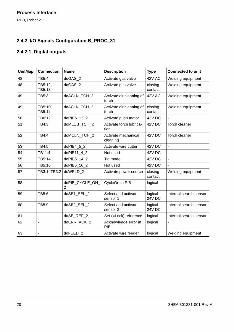
2.4.2 I/O Signals Configuration B_PROC_31
2.4.2.1 Digital outputs
UnitMap Connection Name Description Type Connected to unit
48 TB5:4 doGAS_2 Activate gas valve 42V AC Welding equipment
48 TB5:12, TB5:13
doGAS_2 Activate gas valve closing contact
Welding equipment
49 TB5:3 doACLN_TCH_2 Activate air cleaning of torch
42V AC Welding equipment
49 TB5:10, TB5:11
doACLN_TCH_2 Activate air cleaning of torch
closing contact
Welding equipment
50 TB6:12 doPIB6_12_2 Activate push motor 42V DC -
51 TB4:3 doMLUB_TCH_2 Activate torch lubrica-tion
42V DC Torch cleaner
52 TB4:4 doMCLN_TCH_2 Activate mechanical cleaning
42V DC Torch cleaner
53 TB4:5 doPIB4_5_2 Activate wire cutter 42V DC -
54 TB11:4 doPIB11_4_2 Not used 42V DC -
55 TB5:14 doPIB5_14_2 Tig mode 42V DC -
56 TB5:16 doPIB5_16_2 Not used 42V DC -
57 TB3:1, TB3:2 doWELD_2 Activate power source closing contact
Welding equipment
58 - doPIB_CYCLE_ON_2
CycleOn to PIB logical -
59 TB5:6 doSE1_SEL_2 Select and activate sensor 1
logical24V DC
Internal search sensor
60 TB5:9 doSE2_SEL_2 Select and activate sensor 2
logical24V DC
Internal search sensor
61 - doSE_REF_2 Set (=Lock) reference logical Internal search sensor
62 - doERR_ACK_2 Acknowledge error in PIB
logical -
63 - doFEED_2 Activate wire feeder logical Welding equipment
Process InterfaceRPB, Robot 2
3HEA 801231-001 Rev A 21
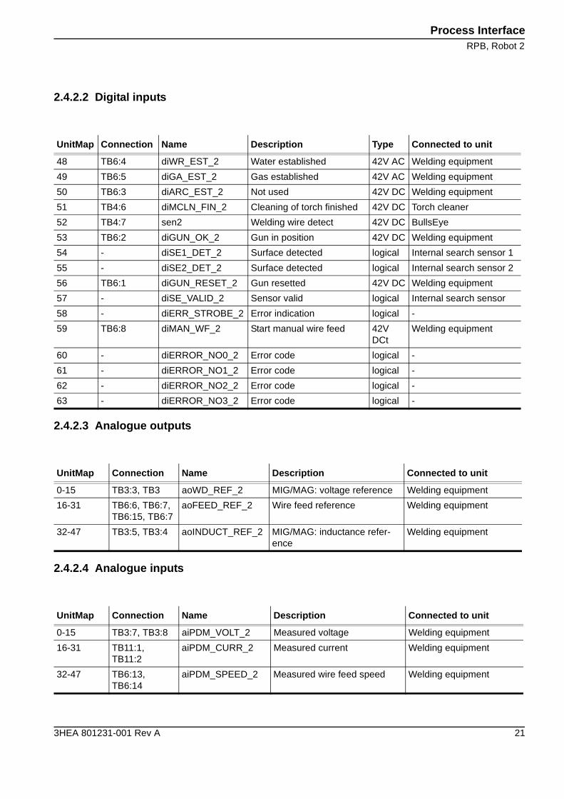
2.4.2.2 Digital inputs
2.4.2.3 Analogue outputs
2.4.2.4 Analogue inputs
UnitMap Connection Name Description Type Connected to unit
48 TB6:4 diWR_EST_2 Water established 42V AC Welding equipment
49 TB6:5 diGA_EST_2 Gas established 42V AC Welding equipment
50 TB6:3 diARC_EST_2 Not used 42V DC Welding equipment
51 TB4:6 diMCLN_FIN_2 Cleaning of torch finished 42V DC Torch cleaner
52 TB4:7 sen2 Welding wire detect 42V DC BullsEye
53 TB6:2 diGUN_OK_2 Gun in position 42V DC Welding equipment
54 - diSE1_DET_2 Surface detected logical Internal search sensor 1
55 - diSE2_DET_2 Surface detected logical Internal search sensor 2
56 TB6:1 diGUN_RESET_2 Gun resetted 42V DC Welding equipment
57 - diSE_VALID_2 Sensor valid logical Internal search sensor
58 - diERR_STROBE_2 Error indication logical -
59 TB6:8 diMAN_WF_2 Start manual wire feed 42V DCt
Welding equipment
60 - diERROR_NO0_2 Error code logical -
61 - diERROR_NO1_2 Error code logical -
62 - diERROR_NO2_2 Error code logical -
63 - diERROR_NO3_2 Error code logical -
UnitMap Connection Name Description Connected to unit
0-15 TB3:3, TB3 aoWD_REF_2 MIG/MAG: voltage reference Welding equipment
16-31 TB6:6, TB6:7,TB6:15, TB6:7
aoFEED_REF_2 Wire feed reference Welding equipment
32-47 TB3:5, TB3:4 aoINDUCT_REF_2 MIG/MAG: inductance refer-ence
Welding equipment
UnitMap Connection Name Description Connected to unit
0-15 TB3:7, TB3:8 aiPDM_VOLT_2 Measured voltage Welding equipment
16-31 TB11:1, TB11:2
aiPDM_CURR_2 Measured current Welding equipment
32-47 TB6:13, TB6:14
aiPDM_SPEED_2 Measured wire feed speed Welding equipment
Process Interface
Fronius
22 3HEA 801231-001 Rev A
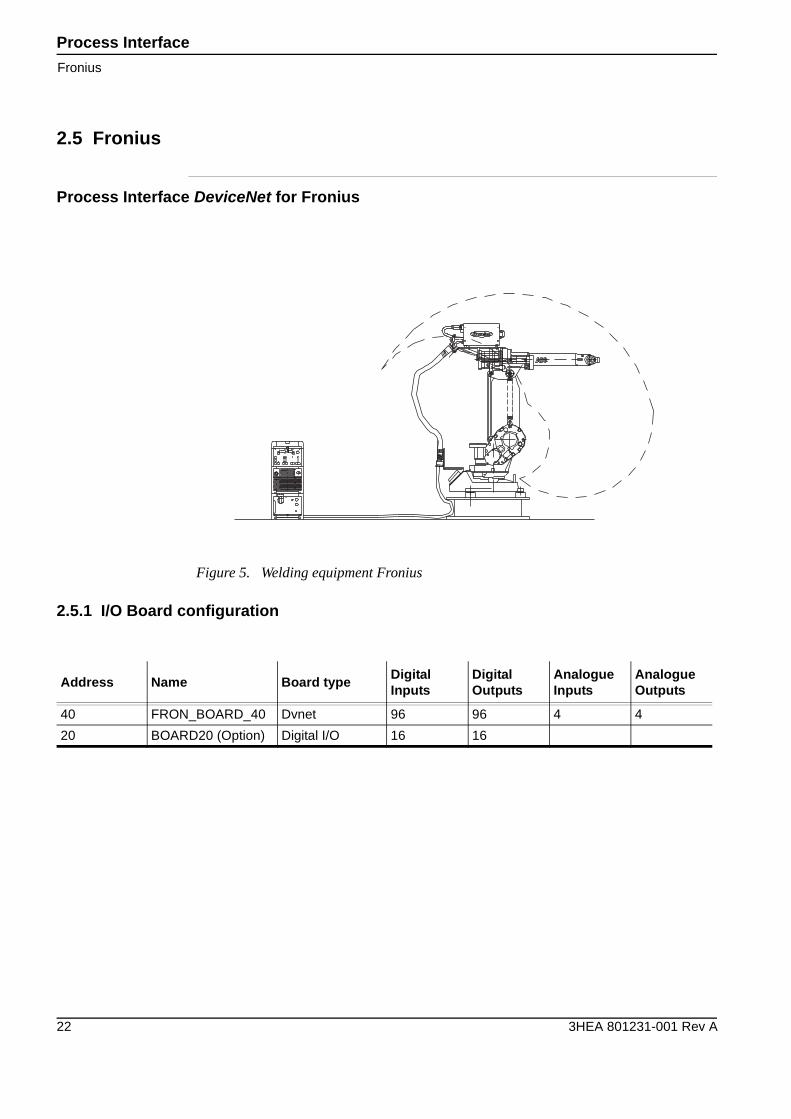
2.5 Fronius
Process Interface DeviceNet for Fronius
2.5.1 I/O Board configuration
Figure 5. Welding equipment Fronius
Address Name Board typeDigitalInputs
DigitalOutputs
AnalogueInputs
AnalogueOutputs
40 FRON_BOARD_40 Dvnet 96 96 4 4
20 BOARD20 (Option) Digital I/O 16 16
Process InterfaceFronius
3HEA 801231-001 Rev A 23
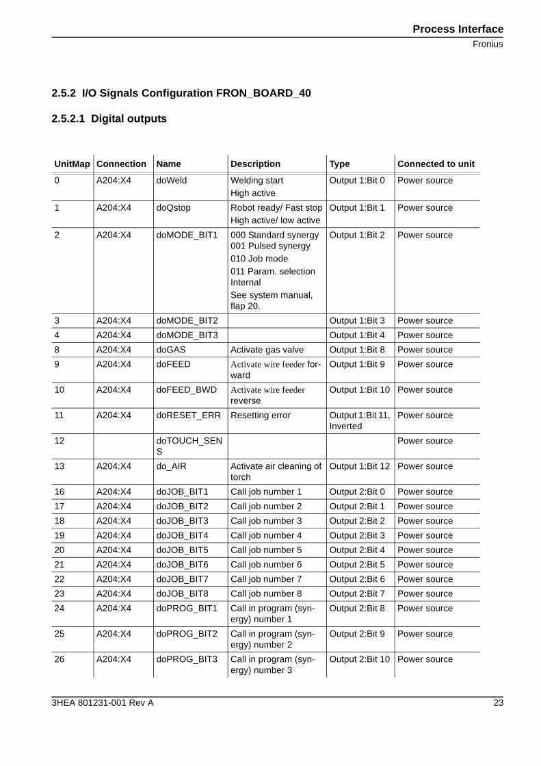
2.5.2 I/O Signals Configuration FRON_BOARD_40
2.5.2.1 Digital outputs
UnitMap Connection Name Description Type Connected to unit
0 A204:X4 doWeld Welding startHigh active
Output 1:Bit 0 Power source
1 A204:X4 doQstop Robot ready/ Fast stopHigh active/ low active
Output 1:Bit 1 Power source
2 A204:X4 doMODE_BIT1 000 Standard synergy001 Pulsed synergy010 Job mode011 Param. selection InternalSee system manual, flap 20.
Output 1:Bit 2 Power source
3 A204:X4 doMODE_BIT2 Output 1:Bit 3 Power source
4 A204:X4 doMODE_BIT3 Output 1:Bit 4 Power source
8 A204:X4 doGAS Activate gas valve Output 1:Bit 8 Power source
9 A204:X4 doFEED Activate wire feeder for-ward
Output 1:Bit 9 Power source
10 A204:X4 doFEED_BWD Activate wire feeder reverse
Output 1:Bit 10 Power source
11 A204:X4 doRESET_ERR Resetting error Output 1:Bit 11, Inverted
Power source
12 doTOUCH_SENS
Power source
13 A204:X4 do_AIR Activate air cleaning of torch
Output 1:Bit 12 Power source
16 A204:X4 doJOB_BIT1 Call job number 1 Output 2:Bit 0 Power source
17 A204:X4 doJOB_BIT2 Call job number 2 Output 2:Bit 1 Power source
18 A204:X4 doJOB_BIT3 Call job number 3 Output 2:Bit 2 Power source
19 A204:X4 doJOB_BIT4 Call job number 4 Output 2:Bit 3 Power source
20 A204:X4 doJOB_BIT5 Call job number 5 Output 2:Bit 4 Power source
21 A204:X4 doJOB_BIT6 Call job number 6 Output 2:Bit 5 Power source
22 A204:X4 doJOB_BIT7 Call job number 7 Output 2:Bit 6 Power source
23 A204:X4 doJOB_BIT8 Call job number 8 Output 2:Bit 7 Power source
24 A204:X4 doPROG_BIT1 Call in program (syn-ergy) number 1
Output 2:Bit 8 Power source
25 A204:X4 doPROG_BIT2 Call in program (syn-ergy) number 2
Output 2:Bit 9 Power source
26 A204:X4 doPROG_BIT3 Call in program (syn-ergy) number 3
Output 2:Bit 10 Power source
Process Interface
Fronius
24 3HEA 801231-001 Rev A
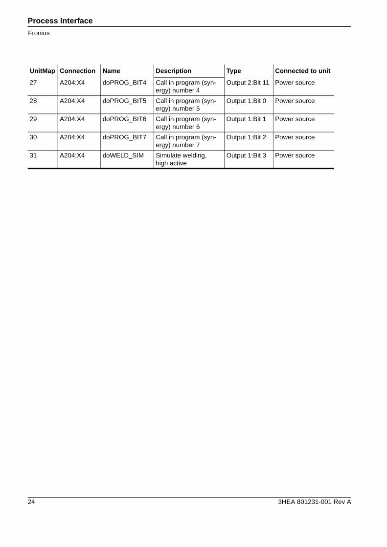
27 A204:X4 doPROG_BIT4 Call in program (syn-ergy) number 4
Output 2:Bit 11 Power source
28 A204:X4 doPROG_BIT5 Call in program (syn-ergy) number 5
Output 1:Bit 0 Power source
29 A204:X4 doPROG_BIT6 Call in program (syn-ergy) number 6
Output 1:Bit 1 Power source
30 A204:X4 doPROG_BIT7 Call in program (syn-ergy) number 7
Output 1:Bit 2 Power source
31 A204:X4 doWELD_SIM Simulate welding,high active
Output 1:Bit 3 Power source
UnitMap Connection Name Description Type Connected to unit
Process InterfaceFronius
3HEA 801231-001 Rev A 25
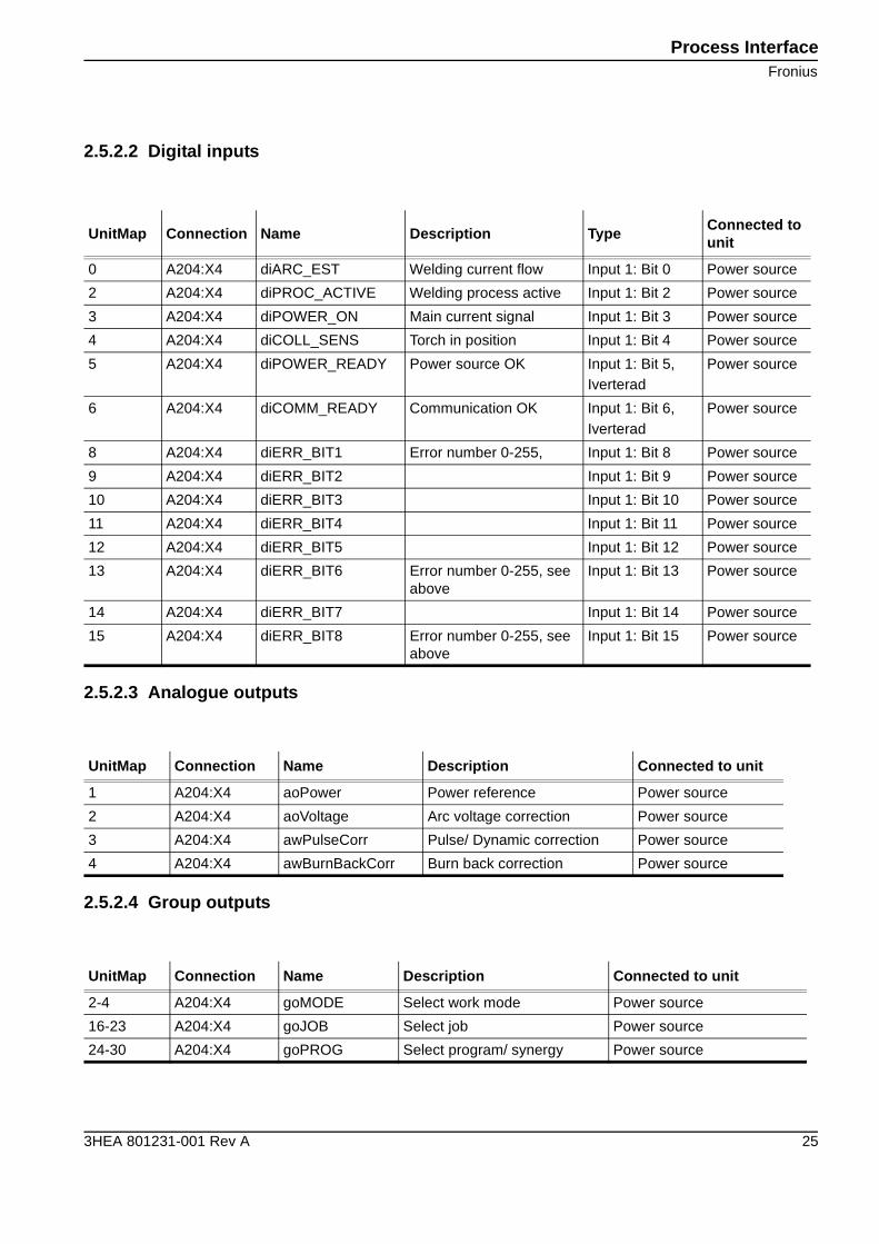
2.5.2.2 Digital inputs
2.5.2.3 Analogue outputs
2.5.2.4 Group outputs
UnitMap Connection Name Description TypeConnected to unit
0 A204:X4 diARC_EST Welding current flow Input 1: Bit 0 Power source
2 A204:X4 diPROC_ACTIVE Welding process active Input 1: Bit 2 Power source
3 A204:X4 diPOWER_ON Main current signal Input 1: Bit 3 Power source
4 A204:X4 diCOLL_SENS Torch in position Input 1: Bit 4 Power source
5 A204:X4 diPOWER_READY Power source OK Input 1: Bit 5,Iverterad
Power source
6 A204:X4 diCOMM_READY Communication OK Input 1: Bit 6,Iverterad
Power source
8 A204:X4 diERR_BIT1 Error number 0-255, Input 1: Bit 8 Power source
9 A204:X4 diERR_BIT2 Input 1: Bit 9 Power source
10 A204:X4 diERR_BIT3 Input 1: Bit 10 Power source
11 A204:X4 diERR_BIT4 Input 1: Bit 11 Power source
12 A204:X4 diERR_BIT5 Input 1: Bit 12 Power source
13 A204:X4 diERR_BIT6 Error number 0-255, see above
Input 1: Bit 13 Power source
14 A204:X4 diERR_BIT7 Input 1: Bit 14 Power source
15 A204:X4 diERR_BIT8 Error number 0-255, see above
Input 1: Bit 15 Power source
UnitMap Connection Name Description Connected to unit
1 A204:X4 aoPower Power reference Power source
2 A204:X4 aoVoltage Arc voltage correction Power source
3 A204:X4 awPulseCorr Pulse/ Dynamic correction Power source
4 A204:X4 awBurnBackCorr Burn back correction Power source
UnitMap Connection Name Description Connected to unit
2-4 A204:X4 goMODE Select work mode Power source
16-23 A204:X4 goJOB Select job Power source
24-30 A204:X4 goPROG Select program/ synergy Power source
Process Interface
Fronius
26 3HEA 801231-001 Rev A
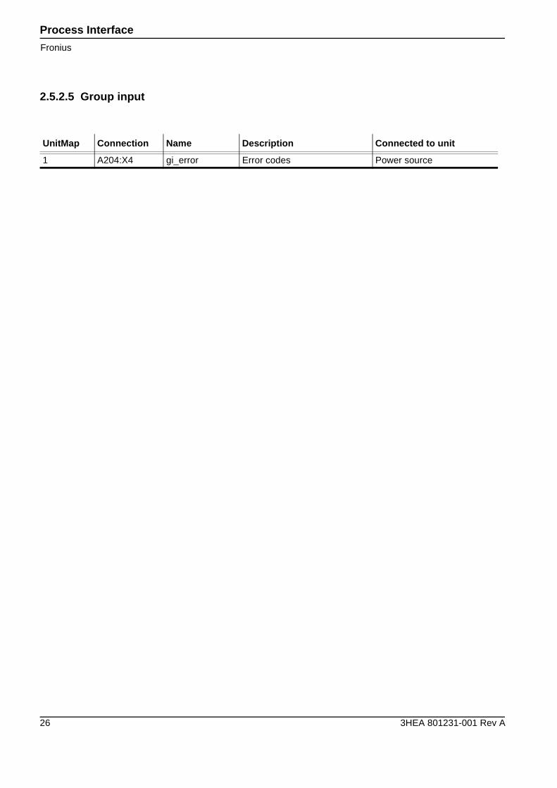
2.5.2.5 Group input
UnitMap Connection Name Description Connected to unit
1 A204:X4 gi_error Error codes Power source
Process InterfaceFronius
3HEA 801231-001 Rev A 27
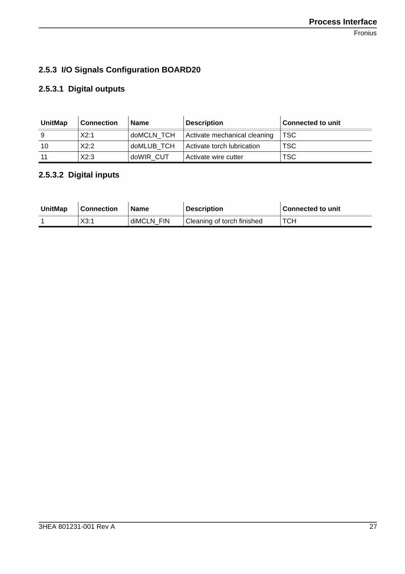
2.5.3 I/O Signals Configuration BOARD20
2.5.3.1 Digital outputs
2.5.3.2 Digital inputs
UnitMap Connection Name Description Connected to unit
9 X2:1 doMCLN_TCH Activate mechanical cleaning TSC
10 X2:2 doMLUB_TCH Activate torch lubrication TSC
11 X2:3 doWIR_CUT Activate wire cutter TSC
UnitMap Connection Name Description Connected to unit
1 X3:1 diMCLN_FIN Cleaning of torch finished TCH
Process Interface
Fronius, Robot 2
28 3HEA 801231-001 Rev A
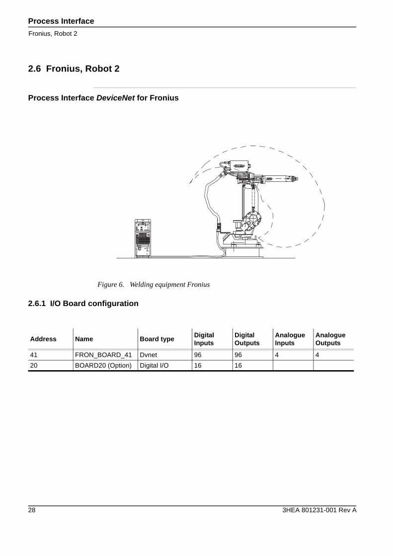
2.6 Fronius, Robot 2
Process Interface DeviceNet for Fronius
2.6.1 I/O Board configuration
Figure 6. Welding equipment Fronius
Address Name Board typeDigitalInputs
DigitalOutputs
AnalogueInputs
AnalogueOutputs
41 FRON_BOARD_41 Dvnet 96 96 4 4
20 BOARD20 (Option) Digital I/O 16 16
Process InterfaceFronius, Robot 2
3HEA 801231-001 Rev A 29
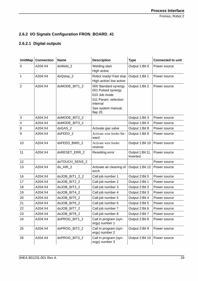
2.6.2 I/O Signals Configuration FRON_BOARD_41
2.6.2.1 Digital outputs
UnitMap Connection Name Description Type Connected to unit
0 A204:X4 doWeld_2 Welding startHigh active
Output 1:Bit 0 Power source
1 A204:X4 doQstop_2 Robot ready/ Fast stopHigh active/ low active
Output 1:Bit 1 Power source
2 A204:X4 doMODE_BIT1_2 000 Standard synergy001 Pulsed synergy010 Job mode011 Param. selection InternalSee system manual, flap 20.
Output 1:Bit 2 Power source
3 A204:X4 doMODE_BIT2_2 Output 1:Bit 3 Power source
4 A204:X4 doMODE_BIT3_2 Output 1:Bit 4 Power source
8 A204:X4 doGAS_2 Activate gas valve Output 1:Bit 8 Power source
9 A204:X4 doFEED_2 Activate wire feeder for-ward
Output 1:Bit 9 Power source
10 A204:X4 doFEED_BWD_2 Activate wire feeder reverse
Output 1:Bit 10 Power source
11 A204:X4 doRESET_ERR_2 Resetting error Output 1:Bit 11, Inverted
Power source
12 doTOUCH_SENS_2 Power source
13 A204:X4 do_AIR_2 Activate air cleaning of torch
Output 1:Bit 12 Power source
16 A204:X4 doJOB_BIT1_2_2 Call job number 1 Output 2:Bit 0 Power source
17 A204:X4 doJOB_BIT2_2 Call job number 2 Output 2:Bit 1 Power source
18 A204:X4 doJOB_BIT3_2 Call job number 3 Output 2:Bit 2 Power source
19 A204:X4 doJOB_BIT4_2 Call job number 4 Output 2:Bit 3 Power source
20 A204:X4 doJOB_BIT5_2 Call job number 5 Output 2:Bit 4 Power source
21 A204:X4 doJOB_BIT6_2 Call job number 6 Output 2:Bit 5 Power source
22 A204:X4 doJOB_BIT7_2 Call job number 7 Output 2:Bit 6 Power source
23 A204:X4 doJOB_BIT8_2 Call job number 8 Output 2:Bit 7 Power source
24 A204:X4 doPROG_BIT1_2 Call in program (syn-ergy) number 1
Output 2:Bit 8 Power source
25 A204:X4 doPROG_BIT2_2 Call in program (syn-ergy) number 2
Output 2:Bit 9 Power source
26 A204:X4 doPROG_BIT3_2 Call in program (syn-ergy) number 3
Output 2:Bit 10 Power source
Process Interface
Fronius, Robot 2
30 3HEA 801231-001 Rev A
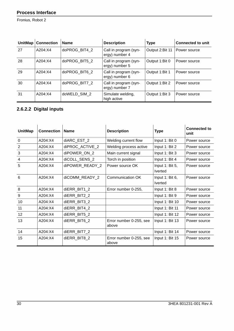
2.6.2.2 Digital inputs
27 A204:X4 doPROG_BIT4_2 Call in program (syn-ergy) number 4
Output 2:Bit 11 Power source
28 A204:X4 doPROG_BIT5_2 Call in program (syn-ergy) number 5
Output 1:Bit 0 Power source
29 A204:X4 doPROG_BIT6_2 Call in program (syn-ergy) number 6
Output 1:Bit 1 Power source
30 A204:X4 doPROG_BIT7_2 Call in program (syn-ergy) number 7
Output 1:Bit 2 Power source
31 A204:X4 doWELD_SIM_2 Simulate welding,high active
Output 1:Bit 3 Power source
UnitMap Connection Name Description Type Connected to unit
UnitMap Connection Name Description TypeConnected to unit
0 A204:X4 diARC_EST_2 Welding current flow Input 1: Bit 0 Power source
2 A204:X4 diPROC_ACTIVE_2 Welding process active Input 1: Bit 2 Power source
3 A204:X4 diPOWER_ON_2 Main current signal Input 1: Bit 3 Power source
4 A204:X4 diCOLL_SENS_2 Torch in position Input 1: Bit 4 Power source
5 A204:X4 diPOWER_READY_2 Power source OK Input 1: Bit 5,Iverted
Power source
6 A204:X4 diCOMM_READY_2 Communication OK Input 1: Bit 6,Iverted
Power source
8 A204:X4 diERR_BIT1_2 Error number 0-255, Input 1: Bit 8 Power source
9 A204:X4 diERR_BIT2_2 Input 1: Bit 9 Power source
10 A204:X4 diERR_BIT3_2 Input 1: Bit 10 Power source
11 A204:X4 diERR_BIT4_2 Input 1: Bit 11 Power source
12 A204:X4 diERR_BIT5_2 Input 1: Bit 12 Power source
13 A204:X4 diERR_BIT6_2 Error number 0-255, see above
Input 1: Bit 13 Power source
14 A204:X4 diERR_BIT7_2 Input 1: Bit 14 Power source
15 A204:X4 diERR_BIT8_2 Error number 0-255, see above
Input 1: Bit 15 Power source
Process InterfaceFronius, Robot 2
3HEA 801231-001 Rev A 31
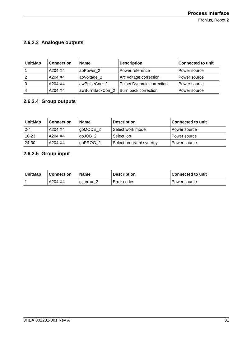
2.6.2.3 Analogue outputs
2.6.2.4 Group outputs
2.6.2.5 Group input
UnitMap Connection Name Description Connected to unit
1 A204:X4 aoPower_2 Power reference Power source
2 A204:X4 aoVoltage_2 Arc voltage correction Power source
3 A204:X4 awPulseCorr_2 Pulse/ Dynamic correction Power source
4 A204:X4 awBurnBackCorr_2 Burn back correction Power source
UnitMap Connection Name Description Connected to unit
2-4 A204:X4 goMODE_2 Select work mode Power source
16-23 A204:X4 goJOB_2 Select job Power source
24-30 A204:X4 goPROG_2 Select program/ synergy Power source
UnitMap Connection Name Description Connected to unit
1 A204:X4 gi_error_2 Error codes Power source
Process Interface
Fronius, Robot 2
32 3HEA 801231-001 Rev A
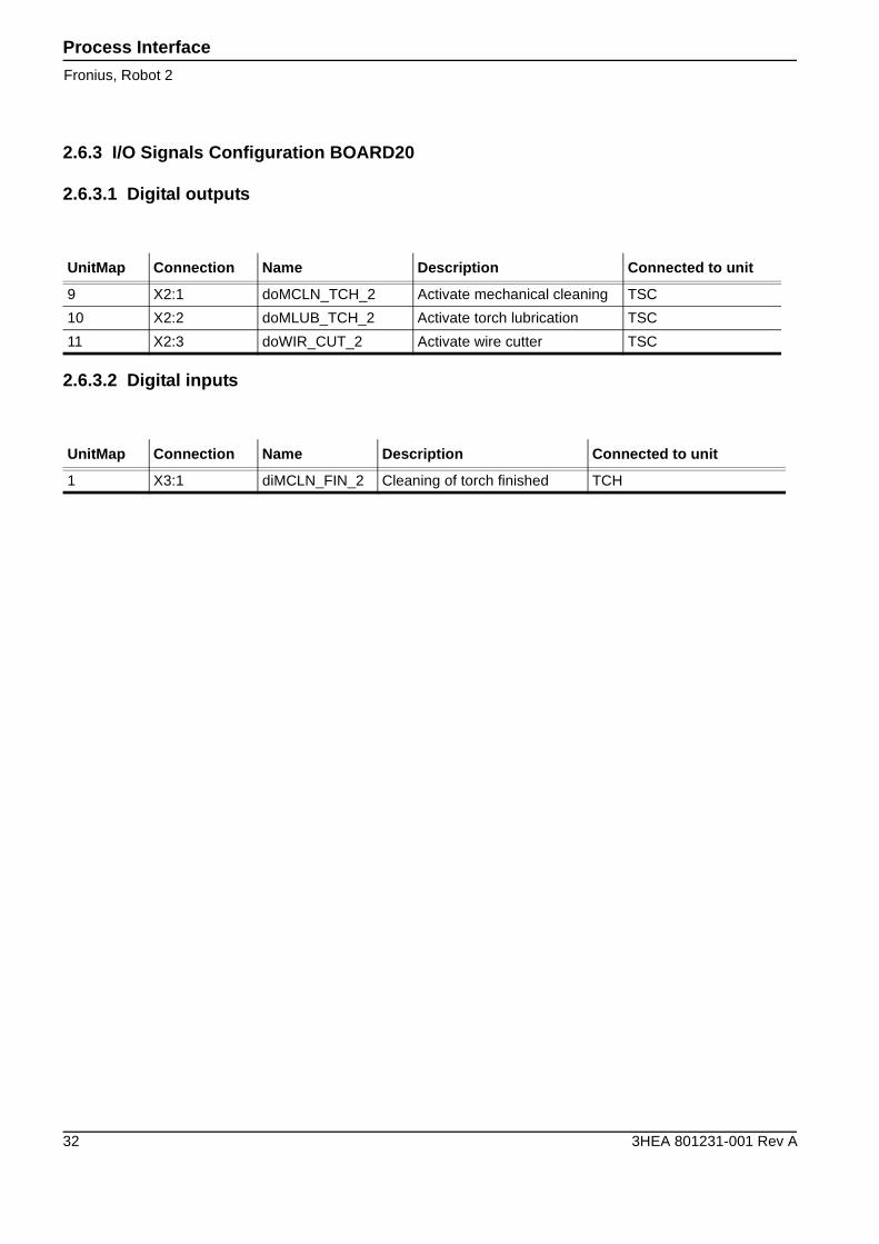
2.6.3 I/O Signals Configuration BOARD20
2.6.3.1 Digital outputs
2.6.3.2 Digital inputs
UnitMap Connection Name Description Connected to unit
9 X2:1 doMCLN_TCH_2 Activate mechanical cleaning TSC
10 X2:2 doMLUB_TCH_2 Activate torch lubrication TSC
11 X2:3 doWIR_CUT_2 Activate wire cutter TSC
UnitMap Connection Name Description Connected to unit
1 X3:1 diMCLN_FIN_2 Cleaning of torch finished TCH

Positioner Interface
3HEA 801231-001 Rev A 33
3 Positioner Interface
General
This chapter describes the I/O configurations for positioners delivered by ABB Technologies AB.These configurations vary depending on which positioner you have:
• For positioner A, see “IRBP A” on page 34.
• For positioner B or D, see “IRBP B/D” on page 43.
• For positioner C, see “IRBP C” on page 47.
• For positioner C Index, see “IRBP C Index” on page 51.
• For positioner K or R, see “IRBP K/R” on page 55.
• For positioner L, see “IRBP L” on page 61.
Positioner Interface
IRBP A
34 3HEA 801231-001 Rev A
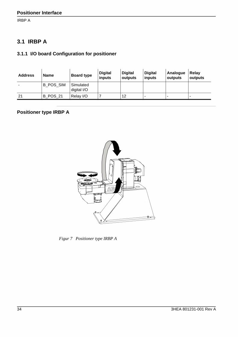
3.1 IRBP A
3.1.1 I/O board Configuration for positioner
Positioner type IRBP A
Address Name Board typeDigitalinputs
Digitaloutputs
Digitalinputs
Analogueoutputs
Relayoutputs
- B_POS_SIM Simulated digital I/O
21 B_POS_21 Relay I/O 7 12 - - -
Figur 7 Positioner type IRBP A
Positioner InterfaceSimulated outputs
3HEA 801231-001 Rev A 35
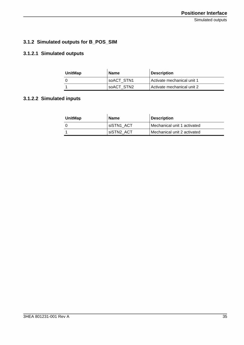
3.1.2 Simulated outputs for B_POS_SIM
3.1.2.1 Simulated outputs
3.1.2.2 Simulated inputs
UnitMap Name Description
0 soACT_STN1 Activate mechanical unit 1
1 soACT_STN2 Activate mechanical unit 2
UnitMap Name Description
0 siSTN1_ACT Mechanical unit 1 activated
1 siSTN2_ACT Mechanical unit 2 activated
Positioner Interface
Digital outputs TB4
36 3HEA 801231-001 Rev A
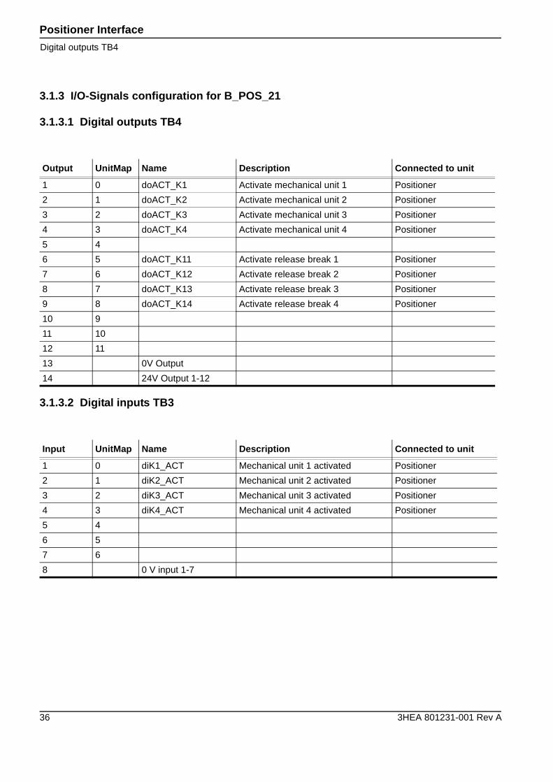
3.1.3 I/O-Signals configuration for B_POS_21
3.1.3.1 Digital outputs TB4
3.1.3.2 Digital inputs TB3
Output UnitMap Name Description Connected to unit
1 0 doACT_K1 Activate mechanical unit 1 Positioner
2 1 doACT_K2 Activate mechanical unit 2 Positioner
3 2 doACT_K3 Activate mechanical unit 3 Positioner
4 3 doACT_K4 Activate mechanical unit 4 Positioner
5 4
6 5 doACT_K11 Activate release break 1 Positioner
7 6 doACT_K12 Activate release break 2 Positioner
8 7 doACT_K13 Activate release break 3 Positioner
9 8 doACT_K14 Activate release break 4 Positioner
10 9
11 10
12 11
13 0V Output
14 24V Output 1-12
Input UnitMap Name Description Connected to unit
1 0 diK1_ACT Mechanical unit 1 activated Positioner
2 1 diK2_ACT Mechanical unit 2 activated Positioner
3 2 diK3_ACT Mechanical unit 3 activated Positioner
4 3 diK4_ACT Mechanical unit 4 activated Positioner
5 4
6 5
7 6
8 0 V input 1-7
Positioner InterfaceDigital inputs TB3
3HEA 801231-001 Rev A 37
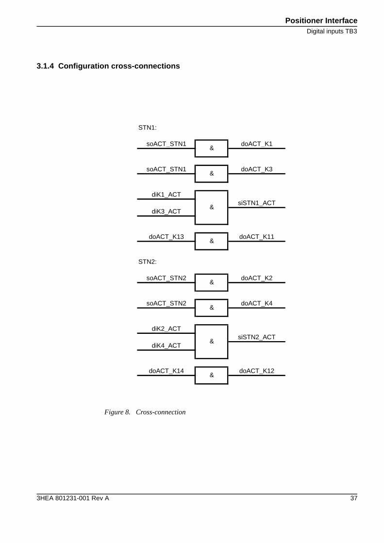
3.1.4 Configuration cross-connections
Figure 8. Cross-connection
STN1:
soACT_STN1 doACT_K1
soACT_STN1 doACT_K3
diK1_ACTsiSTN1_ACT
diK3_ACT
doACT_K13 doACT_K11
STN2:
soACT_STN2 doACT_K2
soACT_STN2 doACT_K4
diK2_ACTsiSTN2_ACT
diK4_ACT
doACT_K14 doACT_K12
&
&
&
&
&
&
&
&
Positioner Interface
IRBP B/D
38 3HEA 801231-001 Rev A
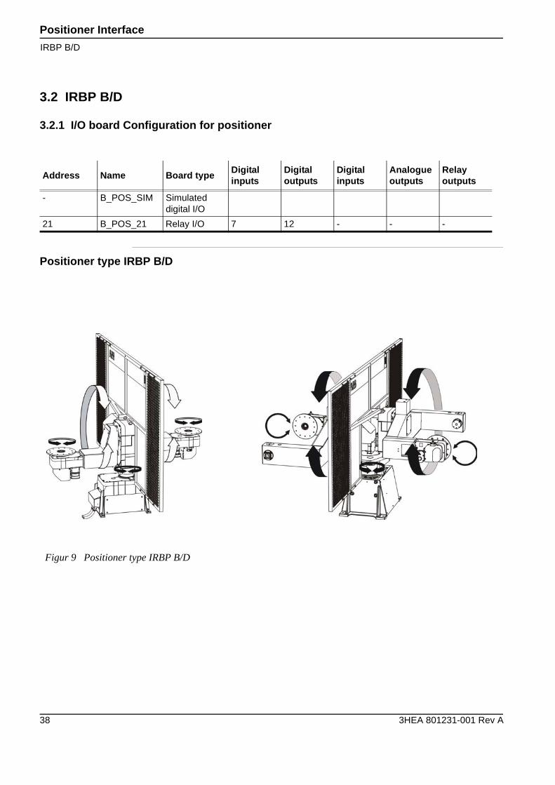
3.2 IRBP B/D
3.2.1 I/O board Configuration for positioner
Positioner type IRBP B/D
Address Name Board typeDigitalinputs
Digitaloutputs
Digitalinputs
Analogueoutputs
Relayoutputs
- B_POS_SIM Simulated digital I/O
21 B_POS_21 Relay I/O 7 12 - - -
Figur 9 Positioner type IRBP B/D
Positioner InterfaceSimulated outputs
3HEA 801231-001 Rev A 39
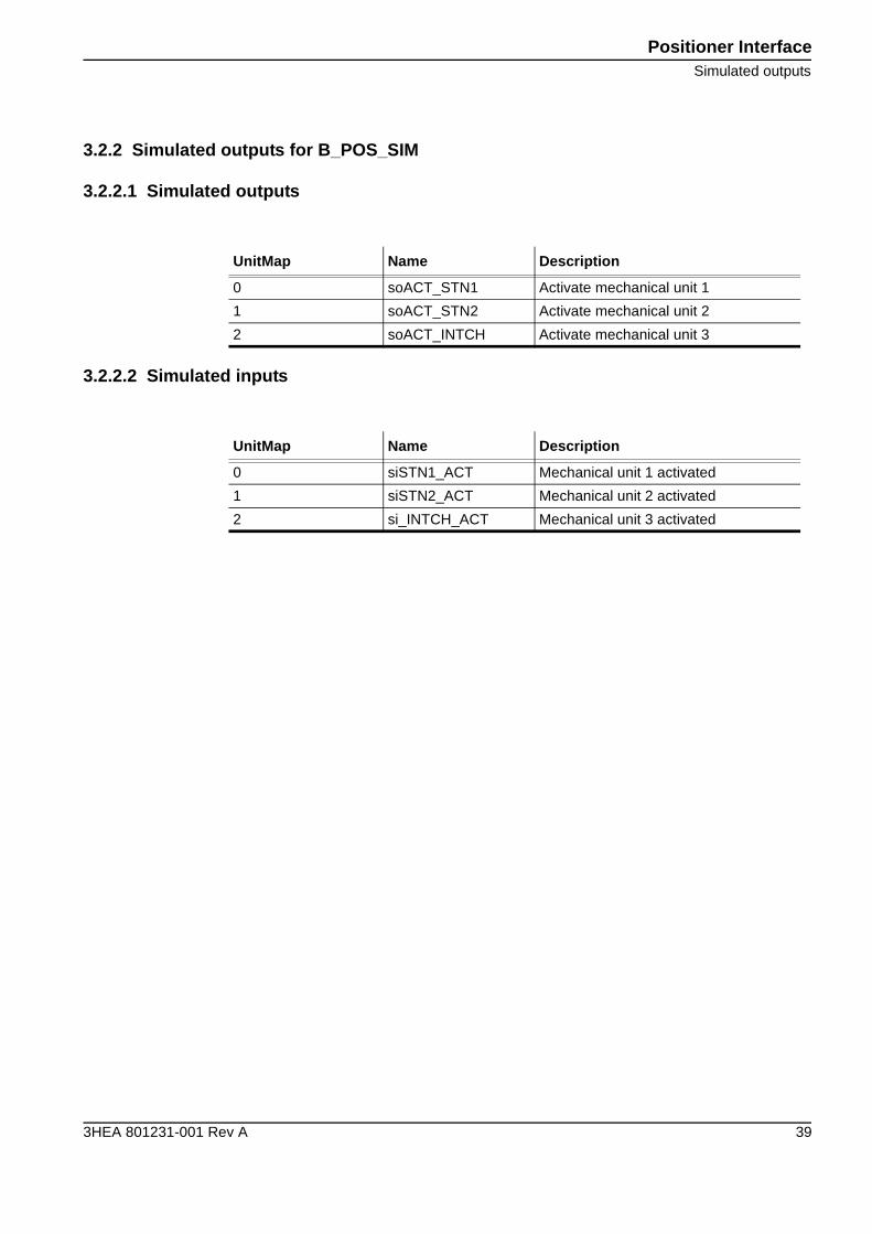
3.2.2 Simulated outputs for B_POS_SIM
3.2.2.1 Simulated outputs
3.2.2.2 Simulated inputs
UnitMap Name Description
0 soACT_STN1 Activate mechanical unit 1
1 soACT_STN2 Activate mechanical unit 2
2 soACT_INTCH Activate mechanical unit 3
UnitMap Name Description
0 siSTN1_ACT Mechanical unit 1 activated
1 siSTN2_ACT Mechanical unit 2 activated
2 si_INTCH_ACT Mechanical unit 3 activated
Positioner Interface
Digital outputs TB4
40 3HEA 801231-001 Rev A
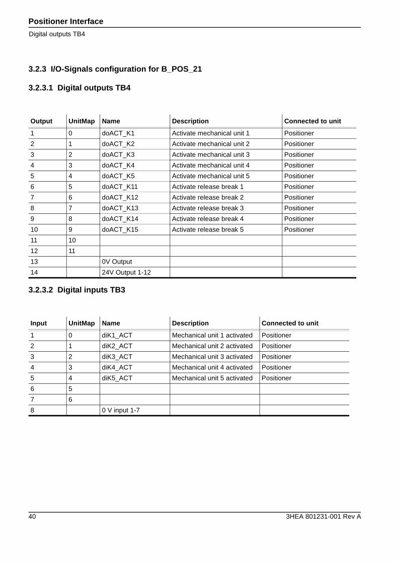
3.2.3 I/O-Signals configuration for B_POS_21
3.2.3.1 Digital outputs TB4
3.2.3.2 Digital inputs TB3
Output UnitMap Name Description Connected to unit
1 0 doACT_K1 Activate mechanical unit 1 Positioner
2 1 doACT_K2 Activate mechanical unit 2 Positioner
3 2 doACT_K3 Activate mechanical unit 3 Positioner
4 3 doACT_K4 Activate mechanical unit 4 Positioner
5 4 doACT_K5 Activate mechanical unit 5 Positioner
6 5 doACT_K11 Activate release break 1 Positioner
7 6 doACT_K12 Activate release break 2 Positioner
8 7 doACT_K13 Activate release break 3 Positioner
9 8 doACT_K14 Activate release break 4 Positioner
10 9 doACT_K15 Activate release break 5 Positioner
11 10
12 11
13 0V Output
14 24V Output 1-12
Input UnitMap Name Description Connected to unit
1 0 diK1_ACT Mechanical unit 1 activated Positioner
2 1 diK2_ACT Mechanical unit 2 activated Positioner
3 2 diK3_ACT Mechanical unit 3 activated Positioner
4 3 diK4_ACT Mechanical unit 4 activated Positioner
5 4 diK5_ACT Mechanical unit 5 activated Positioner
6 5
7 6
8 0 V input 1-7
Positioner InterfaceDigital inputs TB3
3HEA 801231-001 Rev A 41
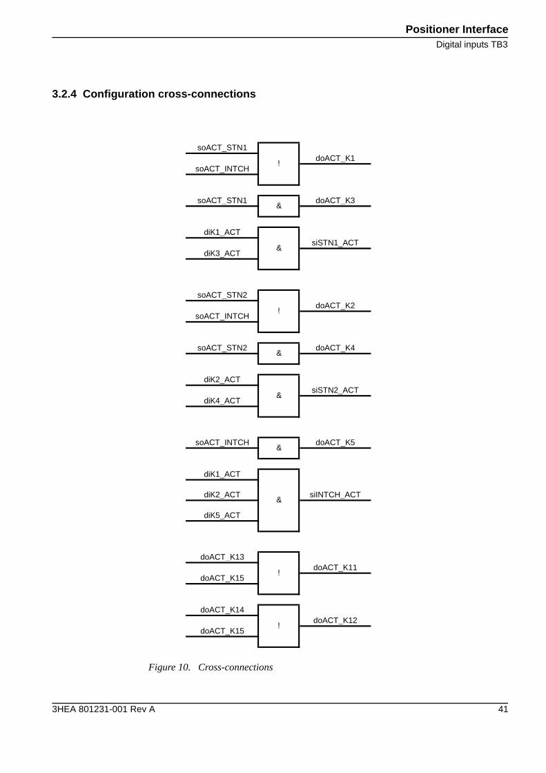
3.2.4 Configuration cross-connections
Figure 10. Cross-connections
soACT_STN1doACT_K1
soACT_INTCH
soACT_STN1 doACT_K3
diK1_ACTsiSTN1_ACT
diK3_ACT
soACT_STN2doACT_K2
soACT_INTCH
soACT_STN2 doACT_K4
diK2_ACTsiSTN2_ACT
diK4_ACT
soACT_INTCH doACT_K5
diK1_ACT
diK2_ACT siINTCH_ACT
diK5_ACT
doACT_K13doACT_K11
doACT_K15
doACT_K14doACT_K12
doACT_K15
!
!
&
&
&
&
!
&
&
!
Positioner Interface
IRBP C
42 3HEA 801231-001 Rev A
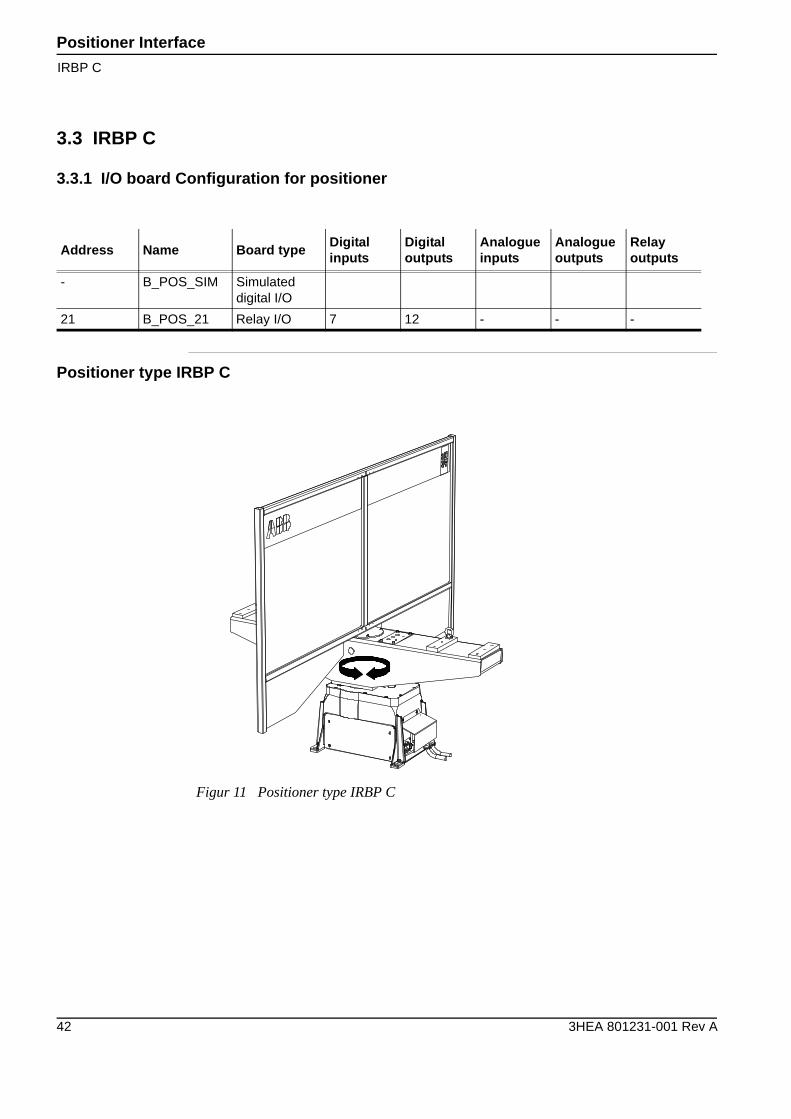
3.3 IRBP C
3.3.1 I/O board Configuration for positioner
Positioner type IRBP C
Address Name Board typeDigitalinputs
Digitaloutputs
Analogueinputs
Analogueoutputs
Relayoutputs
- B_POS_SIM Simulated digital I/O
21 B_POS_21 Relay I/O 7 12 - - -
Figur 11 Positioner type IRBP C

Positioner InterfaceSimulated outputs
3HEA 801231-001 Rev A 43
3.3.2 Simulated outputs for B_POS_SIM
3.3.2.1 Simulated outputs
3.3.2.2 Simulated inputs
UnitMap Name Description
0 soACT_STN1 Activate mechanical unit 1
UnitMap Name Description
0 siSTN1_ACT Mechanical unit 1 activated
Positioner Interface
Digital outputs TB4
44 3HEA 801231-001 Rev A
3.3.3 I/O-Signals configuration for B_POS_21
3.3.3.1 Digital outputs TB4
3.3.3.2 Digital inputs TB3
Output UnitMap Name Description Connected to unit
1 0
2 1
3 2
4 3
5 4 doACT_K5 Activate mechanical unit 1 Positioner
6 5
7 6
8 7
9 8
10 9 doACT_K15 Activate release break 1 Positioner
11 10
12 11
13 0V Output
14 24V Output 1-12
Input UnitMap Name Description Connected to unit
1 0
2 1
3 2
4 3
5 4 diK5_ACT Mechanical unit 1 activated Positioner
6 5 diLS_1_INPOS Limit switch station 1 Station interchange unit
7 6 diLS_2_INPOS Limit switch station 2 Station interchange unit
8 0 V input 1-7
Positioner InterfaceDigital inputs TB3
3HEA 801231-001 Rev A 45
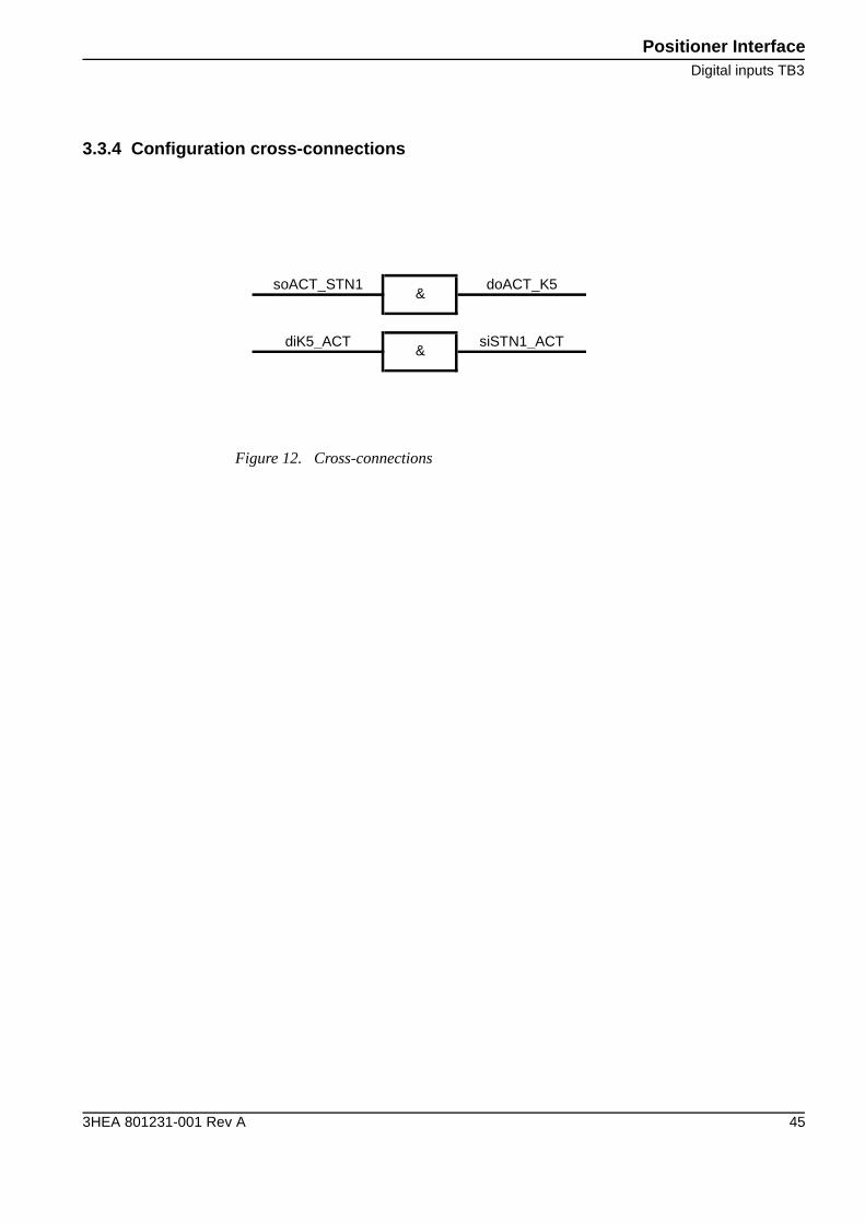
3.3.4 Configuration cross-connections
Figure 12. Cross-connections
soACT_STN1 doACT_K5
diK5_ACT siSTN1_ACT
&
&
Positioner Interface
IRBP C Index
46 3HEA 801231-001 Rev A
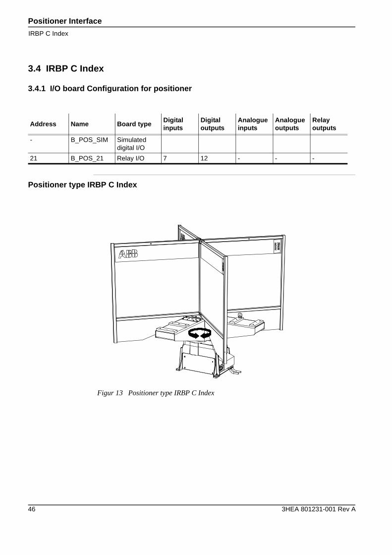
3.4 IRBP C Index
3.4.1 I/O board Configuration for positioner
Positioner type IRBP C Index
Address Name Board typeDigitalinputs
Digitaloutputs
Analogueinputs
Analogueoutputs
Relayoutputs
- B_POS_SIM Simulated digital I/O
21 B_POS_21 Relay I/O 7 12 - - -
Figur 13 Positioner type IRBP C Index
Positioner InterfaceSimulated outputs
3HEA 801231-001 Rev A 47
3.4.2 Simulated outputs for B_POS_SIM
3.4.2.1 Simulated outputs
3.4.2.2 Simulated inputs
UnitMap Name Description
0 soACT_STN1 Activate mechanical unit 1
UnitMap Name Description
0 siSTN1_ACT Mechanical unit 1 activated
Positioner Interface
Digital outputs TB4
48 3HEA 801231-001 Rev A
3.4.3 I/O-Signals configuration for B_POS_21
3.4.3.1 Digital outputs TB4
3.4.3.2 Digital inputs TB3
Output UnitMap Name Description Connected to unit
1 0
2 1
3 2
4 3
5 4 doACT_K5 Activate mechanical unit 1 Positioner
6 5
7 6
8 7
9 8
10 9 doACT_K15 Activate release break 1 Positioner
11 10
12 11
13 0V Output
14 24V Output 1-12
Input UnitMap Name Description Connected to unit
1 0 diLS_2_INPOS Limit switch station 2 Station interchange unit
2 1 diLS_4_INPOS Limit switch station 4 Station interchange unit
3 2
4 3
5 4 diK5_ACT Mechanical unit 1 activated Positioner
6 5 diLS_1_INPOS Limit switch station 1 Station interchange unit
7 6 diLS_3_INPOS Limit switch station 3 Station interchange unit
8 0 V input 1-7
Positioner InterfaceDigital inputs TB3
3HEA 801231-001 Rev A 49
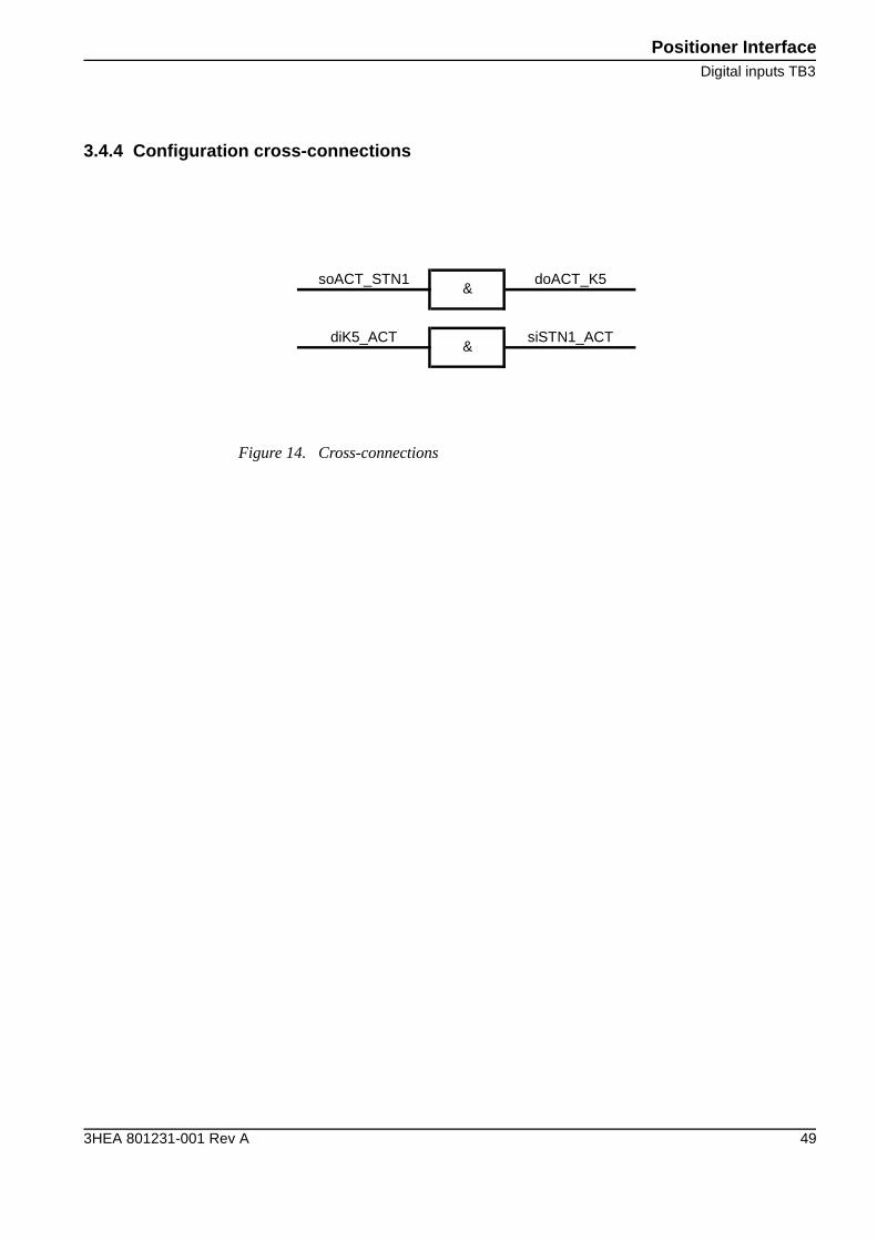
3.4.4 Configuration cross-connections
Figure 14. Cross-connections
soACT_STN1 doACT_K5
diK5_ACT siSTN1_ACT
&
&
Positioner Interface
IRBP K/R
50 3HEA 801231-001 Rev A
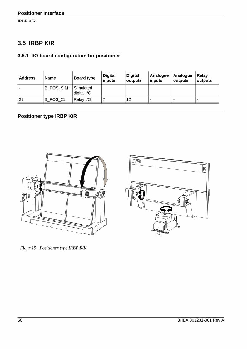
3.5 IRBP K/R
3.5.1 I/O board configuration for positioner
Positioner type IRBP K/R
Address Name Board typeDigitalinputs
Digitaloutputs
Analogueinputs
Analogueoutputs
Relayoutputs
- B_POS_SIM Simulated digital I/O
21 B_POS_21 Relay I/O 7 12 - - -
Figur 15 Positioner type IRBP R/K

Positioner InterfaceSimulated outputs
3HEA 801231-001 Rev A 51
3.5.2 Simulated outputs for B_POS_SIM
3.5.2.1 Simulated outputs
3.5.2.2 Simulated inputs
UnitMap Name Description
0 soACT_STN1 Activate mechanical unit 1
1 soACT_STN2 Activate mechanical unit 2
2 soACT_INTCH Activate mechanical unit 3
UnitMap Name Description
0 siSTN1_ACT Mechanical unit 1 activated
1 siSTN2_ACT Mechanical unit 2 activated
2 siINTCH_ACT Mechanical unit 3 activated
Positioner Interface
Digital outputs TB4
52 3HEA 801231-001 Rev A
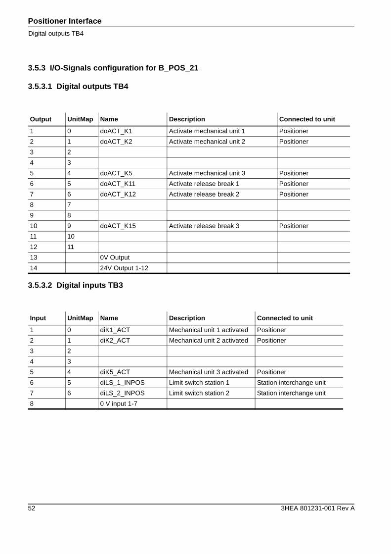
3.5.3 I/O-Signals configuration for B_POS_21
3.5.3.1 Digital outputs TB4
3.5.3.2 Digital inputs TB3
Output UnitMap Name Description Connected to unit
1 0 doACT_K1 Activate mechanical unit 1 Positioner
2 1 doACT_K2 Activate mechanical unit 2 Positioner
3 2
4 3
5 4 doACT_K5 Activate mechanical unit 3 Positioner
6 5 doACT_K11 Activate release break 1 Positioner
7 6 doACT_K12 Activate release break 2 Positioner
8 7
9 8
10 9 doACT_K15 Activate release break 3 Positioner
11 10
12 11
13 0V Output
14 24V Output 1-12
Input UnitMap Name Description Connected to unit
1 0 diK1_ACT Mechanical unit 1 activated Positioner
2 1 diK2_ACT Mechanical unit 2 activated Positioner
3 2
4 3
5 4 diK5_ACT Mechanical unit 3 activated Positioner
6 5 diLS_1_INPOS Limit switch station 1 Station interchange unit
7 6 diLS_2_INPOS Limit switch station 2 Station interchange unit
8 0 V input 1-7
Positioner InterfaceK/R 3DU (3 axes)
3HEA 801231-001 Rev A 53
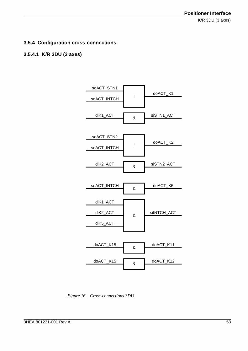
3.5.4 Configuration cross-connections
3.5.4.1 K/R 3DU (3 axes)
Figure 16. Cross-connections 3DU
soACT_STN1doACT_K1
soACT_INTCH
diK1_ACT siSTN1_ACT
soACT_STN2doACT_K2
soACT_INTCH
diK2_ACT siSTN2_ACT
soACT_INTCH doACT_K5
diK1_ACT
diK2_ACT siINTCH_ACT
diK5_ACT
doACT_K15 doACT_K11
doACT_K15 doACT_K12
&
&
&
&
!
&
!
&
Positioner Interface
K/R 1DU (1-axis)
54 3HEA 801231-001 Rev A
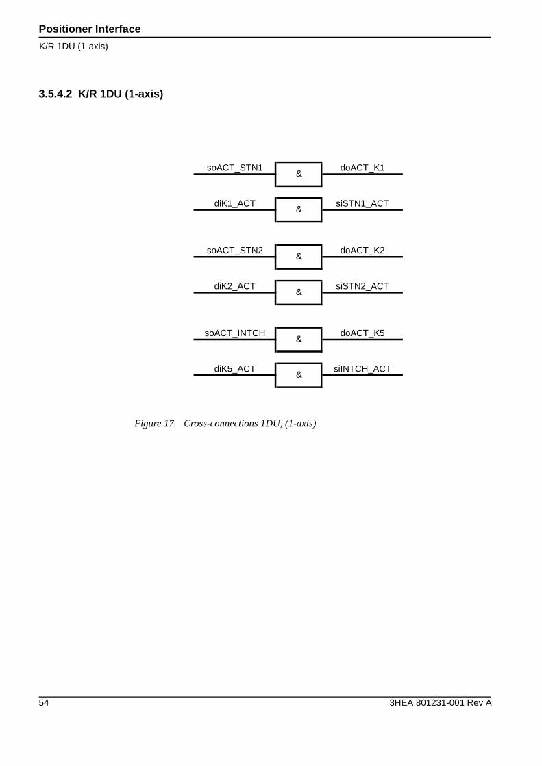
3.5.4.2 K/R 1DU (1-axis)
Figure 17. Cross-connections 1DU, (1-axis)
soACT_STN1 doACT_K1
diK1_ACT siSTN1_ACT
soACT_STN2 doACT_K2
diK2_ACT siSTN2_ACT
soACT_INTCH doACT_K5
diK5_ACT siINTCH_ACT
&
&
&
&
&
&
Positioner InterfaceIRBP L
3HEA 801231-001 Rev A 55
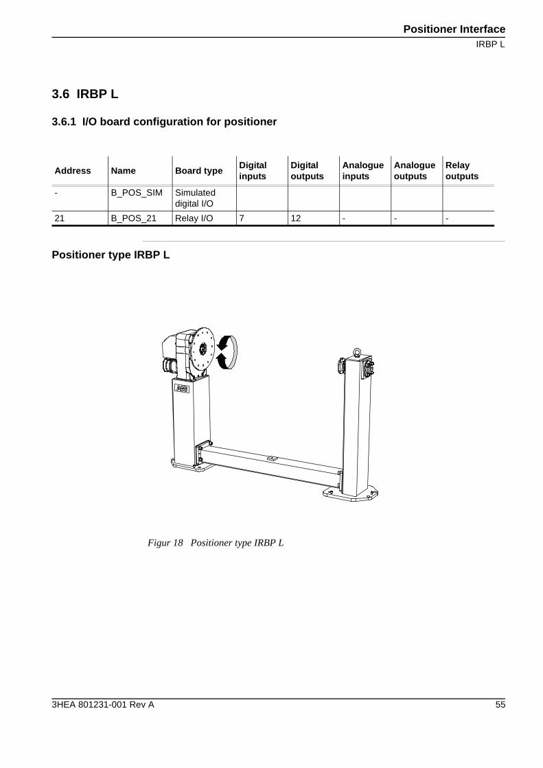
3.6 IRBP L
3.6.1 I/O board configuration for positioner
Positioner type IRBP L
Address Name Board typeDigitalinputs
Digitaloutputs
Analogueinputs
Analogueoutputs
Relayoutputs
- B_POS_SIM Simulated digital I/O
21 B_POS_21 Relay I/O 7 12 - - -
Figur 18 Positioner type IRBP L
Positioner Interface
Simulated outputs
56 3HEA 801231-001 Rev A
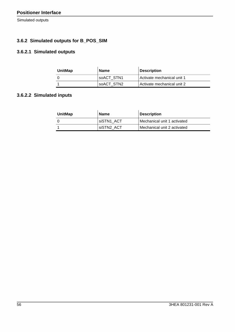
3.6.2 Simulated outputs for B_POS_SIM
3.6.2.1 Simulated outputs
3.6.2.2 Simulated inputs
UnitMap Name Description
0 soACT_STN1 Activate mechanical unit 1
1 soACT_STN2 Activate mechanical unit 2
UnitMap Name Description
0 siSTN1_ACT Mechanical unit 1 activated
1 siSTN2_ACT Mechanical unit 2 activated
Positioner InterfaceDigital outputs TB4
3HEA 801231-001 Rev A 57
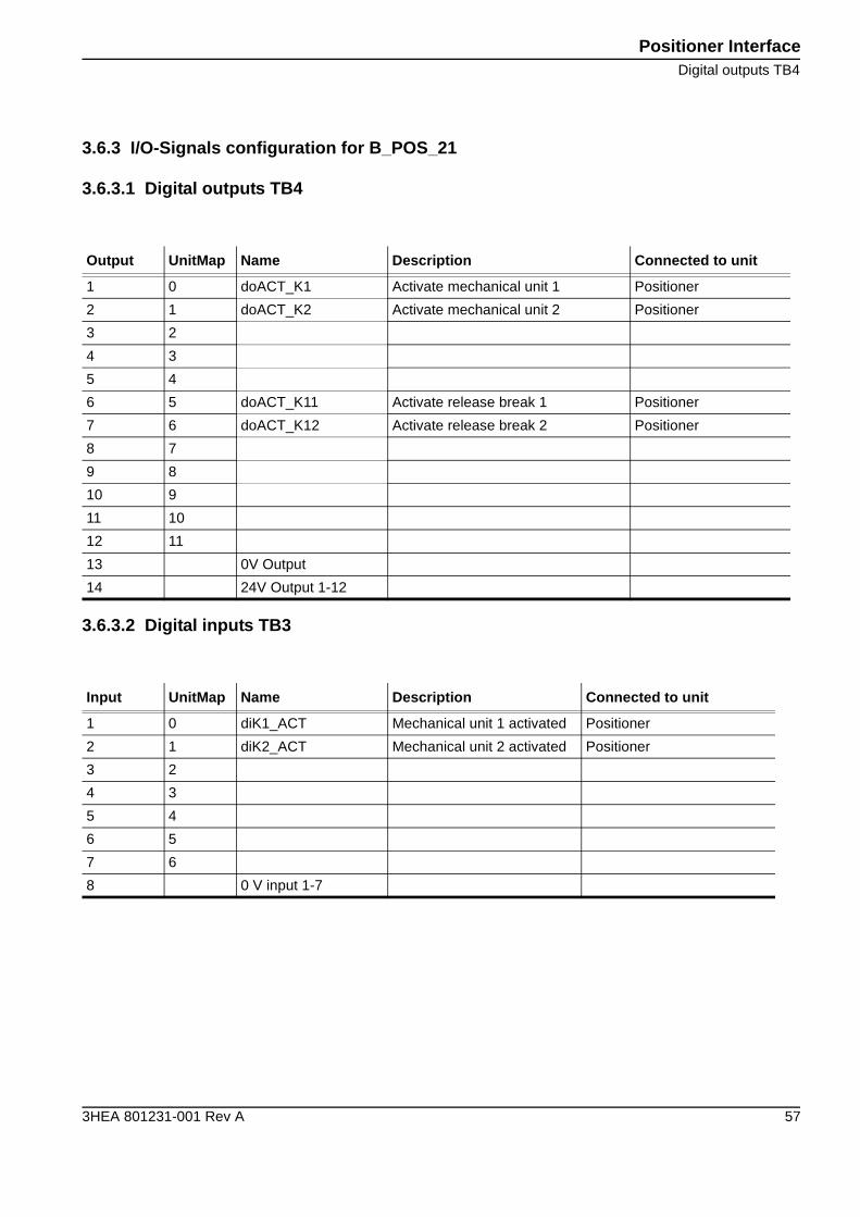
3.6.3 I/O-Signals configuration for B_POS_21
3.6.3.1 Digital outputs TB4
3.6.3.2 Digital inputs TB3
Output UnitMap Name Description Connected to unit
1 0 doACT_K1 Activate mechanical unit 1 Positioner
2 1 doACT_K2 Activate mechanical unit 2 Positioner
3 2
4 3
5 4
6 5 doACT_K11 Activate release break 1 Positioner
7 6 doACT_K12 Activate release break 2 Positioner
8 7
9 8
10 9
11 10
12 11
13 0V Output
14 24V Output 1-12
Input UnitMap Name Description Connected to unit
1 0 diK1_ACT Mechanical unit 1 activated Positioner
2 1 diK2_ACT Mechanical unit 2 activated Positioner
3 2
4 3
5 4
6 5
7 6
8 0 V input 1-7
Positioner Interface
Digital inputs TB3
58 3HEA 801231-001 Rev A
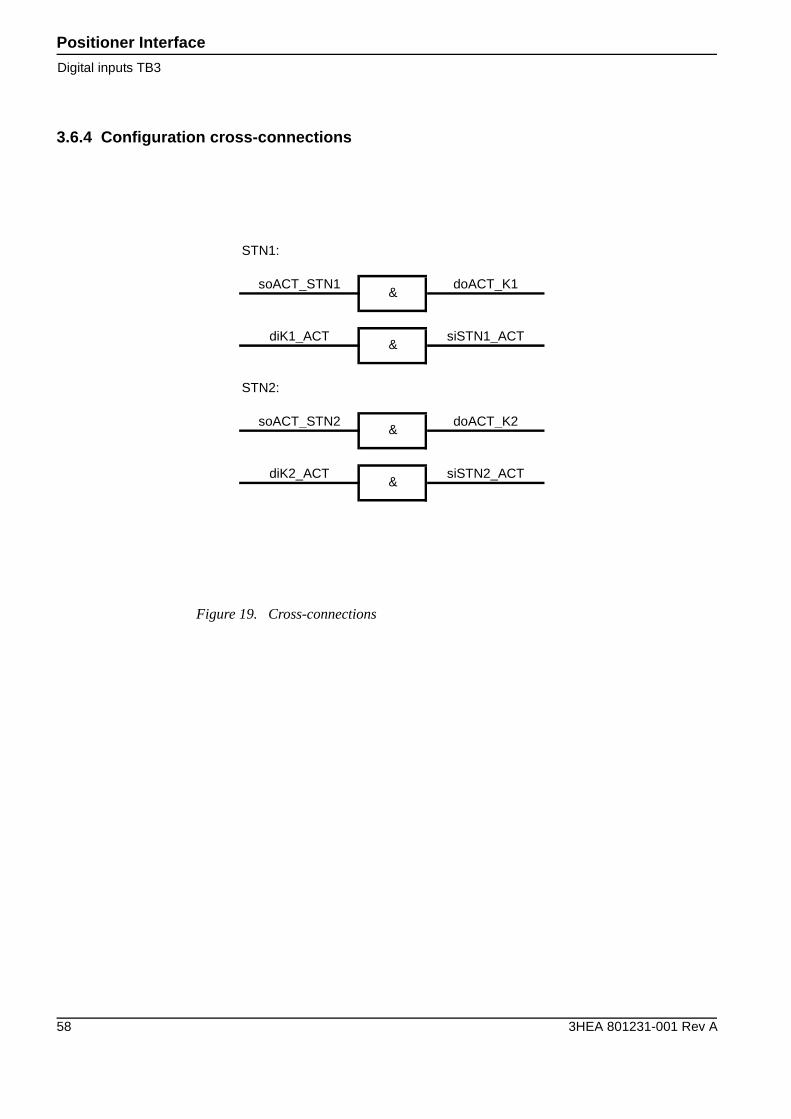
3.6.4 Configuration cross-connections
Figure 19. Cross-connections
STN1:
soACT_STN1 doACT_K1
diK1_ACT siSTN1_ACT
STN2:
soACT_STN2 doACT_K2
diK2_ACT siSTN2_ACT
&
&
&
&
Operator Interface IRBPI/O board Configuration
3HEA 801231-001 Rev A 59
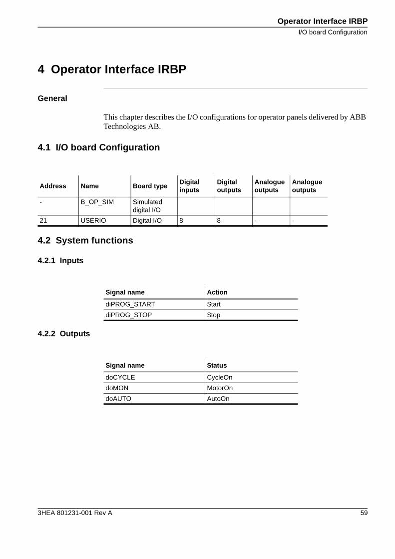
4 Operator Interface IRBP
General
This chapter describes the I/O configurations for operator panels delivered by ABB Technologies AB.
4.1 I/O board Configuration
4.2 System functions
4.2.1 Inputs
4.2.2 Outputs
Address Name Board typeDigitalinputs
Digitaloutputs
Analogueoutputs
Analogueoutputs
- B_OP_SIM Simulated digital I/O
21 USERIO Digital I/O 8 8 - -
Signal name Action
diPROG_START Start
diPROG_STOP Stop
Signal name Status
doCYCLE CycleOn
doMON MotorOn
doAUTO AutoOn
Operator Interface IRBP
I/O-Signals configuration for B_OP_SIM
60 3HEA 801231-001 Rev A
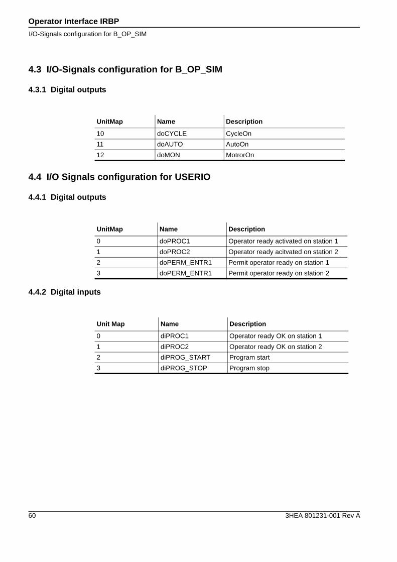
4.3 I/O-Signals configuration for B_OP_SIM
4.3.1 Digital outputs
4.4 I/O Signals configuration for USERIO
4.4.1 Digital outputs
4.4.2 Digital inputs
UnitMap Name Description
10 doCYCLE CycleOn
11 doAUTO AutoOn
12 doMON MotrorOn
UnitMap Name Description
0 doPROC1 Operator ready activated on station 1
1 doPROC2 Operator ready acitvated on station 2
2 doPERM_ENTR1 Permit operator ready on station 1
3 doPERM_ENTR1 Permit operator ready on station 2
Unit Map Name Description
0 diPROC1 Operator ready OK on station 1
1 diPROC2 Operator ready OK on station 2
2 diPROG_START Program start
3 diPROG_STOP Program stop
Safety interface SIB V
3HEA 801231-001 Rev A 61
5 Safety interface SIB V
About this chapter
This chapter describes the different I/O configurations for standard equipment for safety supervision SIB V, delevered by ABB Technologies AB. These configurations vary depending on which positioner you have:
• For positioners B, C, D, K or R, see “Positioner B/C/D/K/R” on page 62.
• For positioner C Index, see “Positioner C Index” on page 71.
• For positioners A, L or S, see “Positioner A/L/S” on page 75.
Safety interface SIB V
Positioner B/C/D/K/R
62 3HEA 801231-001 Rev A
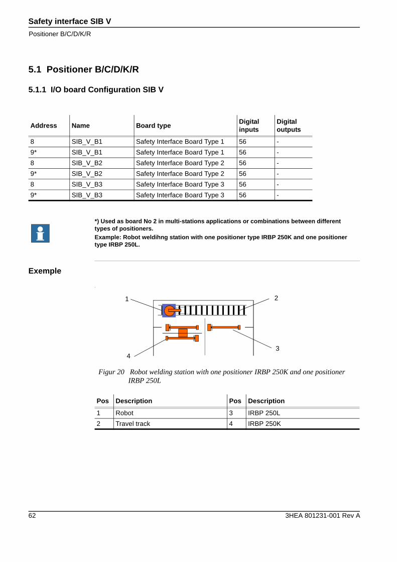
5.1 Positioner B/C/D/K/R
5.1.1 I/O board Configuration SIB V
Exemple
1
Address Name Board typeDigitalinputs
Digitaloutputs
8 SIB_V_B1 Safety Interface Board Type 1 56 -
9* SIB_V_B1 Safety Interface Board Type 1 56 -
8 SIB_V_B2 Safety Interface Board Type 2 56 -
9* SIB_V_B2 Safety Interface Board Type 2 56 -
8 SIB_V_B3 Safety Interface Board Type 3 56 -
9* SIB_V_B3 Safety Interface Board Type 3 56 -
*) Used as board No 2 in multi-stations applications or combinations between different types of positioners.Example: Robot weldihng station with one positioner type IRBP 250K and one positioner type IRBP 250L.
Figur 20 Robot welding station with one positioner IRBP 250K and one positioner IRBP 250L
Pos Description Pos Description
1 Robot 3 IRBP 250L
2 Travel track 4 IRBP 250K
1
4
2
3
Safety interface SIB VDigital inputs
3HEA 801231-001 Rev A 63
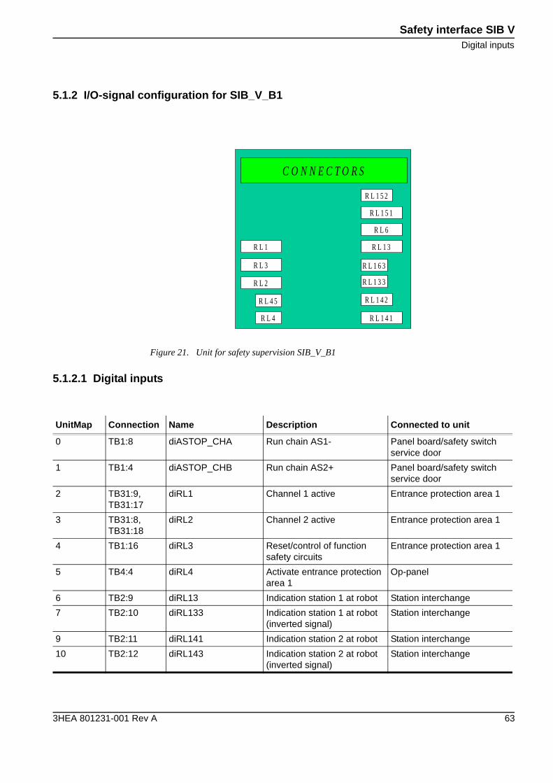
5.1.2 I/O-signal configuration for SIB_V_B1
5.1.2.1 Digital inputs
Figure 21. Unit for safety supervision SIB_V_B1
R L 2
R L 3
R L 1
R L 4
R L 4 5
R L 1 4 1
R L 1 4 2
R L 1 3 3
R L 1 6 3
R L 1 3
R L 6
R L 1 5 1
R L 1 5 2
C O N N E C T O R S
UnitMap Connection Name Description Connected to unit
0 TB1:8 diASTOP_CHA Run chain AS1- Panel board/safety switch service door
1 TB1:4 diASTOP_CHB Run chain AS2+ Panel board/safety switch service door
2 TB31:9, TB31:17
diRL1 Channel 1 active Entrance protection area 1
3 TB31:8, TB31:18
diRL2 Channel 2 active Entrance protection area 1
4 TB1:16 diRL3 Reset/control of function safety circuits
Entrance protection area 1
5 TB4:4 diRL4 Activate entrance protection area 1
Op-panel
6 TB2:9 diRL13 Indication station 1 at robot Station interchange
7 TB2:10 diRL133 Indication station 1 at robot (inverted signal)
Station interchange
9 TB2:11 diRL141 Indication station 2 at robot Station interchange
10 TB2:12 diRL143 Indication station 2 at robot (inverted signal)
Station interchange
Safety interface SIB V
Digital inputs
64 3HEA 801231-001 Rev A
5.1.2.2 Digital inputs
5.1.2.3 Configuration cross-connections
UnitMap Connection Name Description Connected to unit
16 TB1:1 diGSTOP_CHA Run chain GS2+ Panel board
17 TB1:5 diGSTOP_CHB Run chain GS1- Panel board
24 TB111:10, TB31:2
diRL201 Channel 1 active Safety switch service door
25 TB111:8, TB31:4
diRL202 Channel 2 active Safety switch service door
26 TB111:11, TB31:5
diRL203 Reset/control of function safety circuits
Safety switch service door
27 TB111:13, TB31:6
diRL204 Activate safety circuits ser-vice door
Pushbutton service door
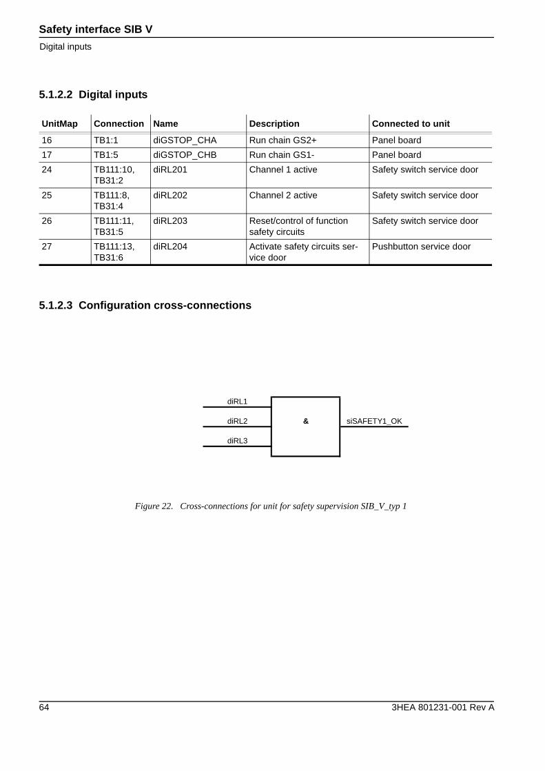
Figure 22. Cross-connections for unit for safety supervision SIB_V_typ 1
diRL1
diRL2 & siSAFETY1_OK
diRL3
Safety interface SIB VPositioner C Index
3HEA 801231-001 Rev A 65
5.2 Positioner C Index
5.2.1 I/O board Configuration SIB V
Exemple
1
Address Name Board typeDigitalinputs
Digitaloutputs
8 SIB_V_B1 Safety Interface Board Type 1 56 -
9* SIB_V_B1 Safety Interface Board Type 1 56 -
8 SIB_V_B2 Safety Interface Board Type 2 56 -
9* SIB_V_B2 Safety Interface Board Type 2 56 -
8 SIB_V_B3 Safety Interface Board Type 3 56 -
9* SIB_V_B3 Safety Interface Board Type 3 56 -
*) Used as board No 2 in multi-stations applications or combinations between different types of positioners.Example: Robot weldihng station with one positioner type IRBP 250K and one positioner type IRBP 250L.
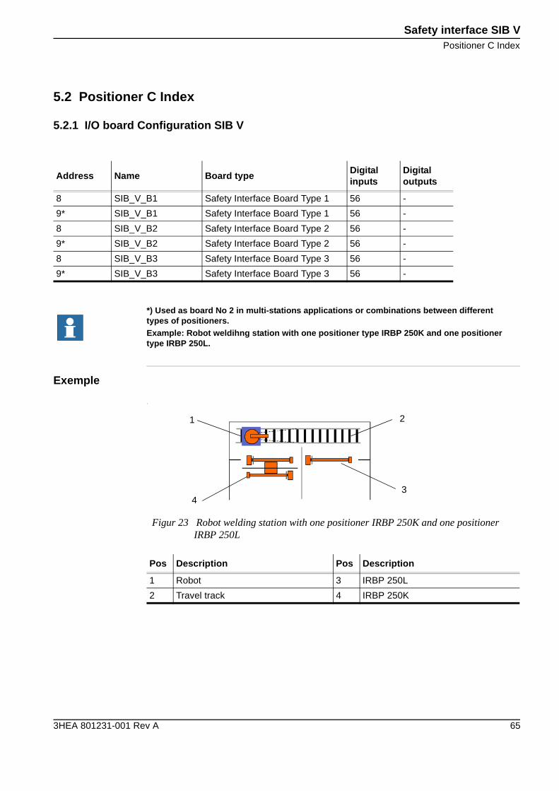
Figur 23 Robot welding station with one positioner IRBP 250K and one positioner IRBP 250L
Pos Description Pos Description
1 Robot 3 IRBP 250L
2 Travel track 4 IRBP 250K
1
4
2
3
Safety interface SIB V
Digital inputs
66 3HEA 801231-001 Rev A
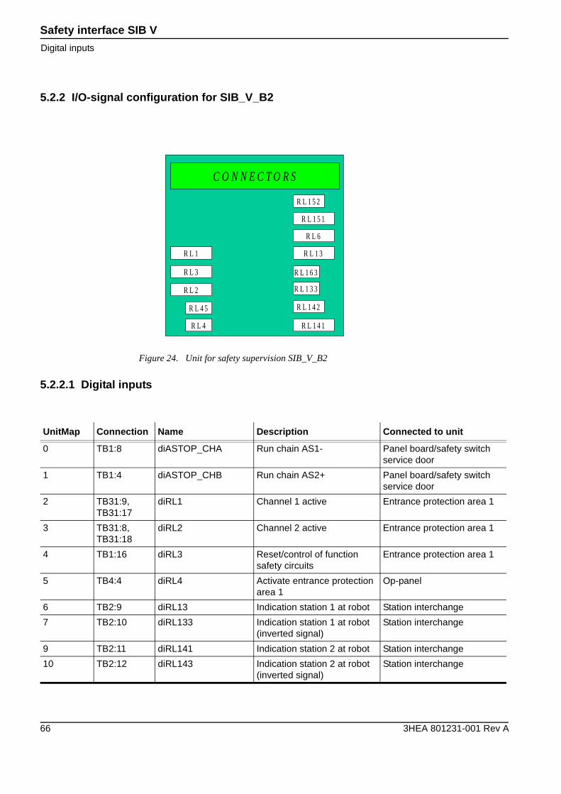
5.2.2 I/O-signal configuration for SIB_V_B2
5.2.2.1 Digital inputs
Figure 24. Unit for safety supervision SIB_V_B2
R L 2
R L 3
R L 1
R L 4
R L 4 5
R L 1 4 1
R L 1 4 2
R L 1 3 3
R L 1 6 3
R L 1 3
R L 6
R L 1 5 1
R L 1 5 2
C O N N E C T O R S
UnitMap Connection Name Description Connected to unit
0 TB1:8 diASTOP_CHA Run chain AS1- Panel board/safety switch service door
1 TB1:4 diASTOP_CHB Run chain AS2+ Panel board/safety switch service door
2 TB31:9, TB31:17
diRL1 Channel 1 active Entrance protection area 1
3 TB31:8, TB31:18
diRL2 Channel 2 active Entrance protection area 1
4 TB1:16 diRL3 Reset/control of function safety circuits
Entrance protection area 1
5 TB4:4 diRL4 Activate entrance protection area 1
Op-panel
6 TB2:9 diRL13 Indication station 1 at robot Station interchange
7 TB2:10 diRL133 Indication station 1 at robot (inverted signal)
Station interchange
9 TB2:11 diRL141 Indication station 2 at robot Station interchange
10 TB2:12 diRL143 Indication station 2 at robot (inverted signal)
Station interchange
Safety interface SIB VDigital inputs
3HEA 801231-001 Rev A 67
5.2.2.2 Digital inputs
5.2.2.3 Configuration cross-connections
UnitMap Connection Name Description Connected to unit
11 TB2:13 diRL151 Indication station 2 at robot Station interchange
12 TB2:14 diRL153 Indication station 2 at robot (inverted signal)
Station interchange
13 TB2:15 diRL16 Indication station 4 at robot Station interchange
14 TB2:16 diRL163 Indication station 4 at robot (inverted signal)
Station interchange
16 TB1:1 diGSTOP_CHA Run chain GS2+ Panel board
17 TB1:5 diGSTOP_CHB Run chain GS1- Panel board
24 TB111:10, TB31:2
diRL201 Channel 1 active Safety switch service door
25 TB111:8, TB31:4
diRL202 Channel 2 active Safety switch service door
26 TB111:11, TB31:5
diRL203 Reset/control of function safety circuits
Safety switch service door
27 TB111:13, TB31:6
diRL204 Activate safety circuits ser-vice door
Pushbutton service door
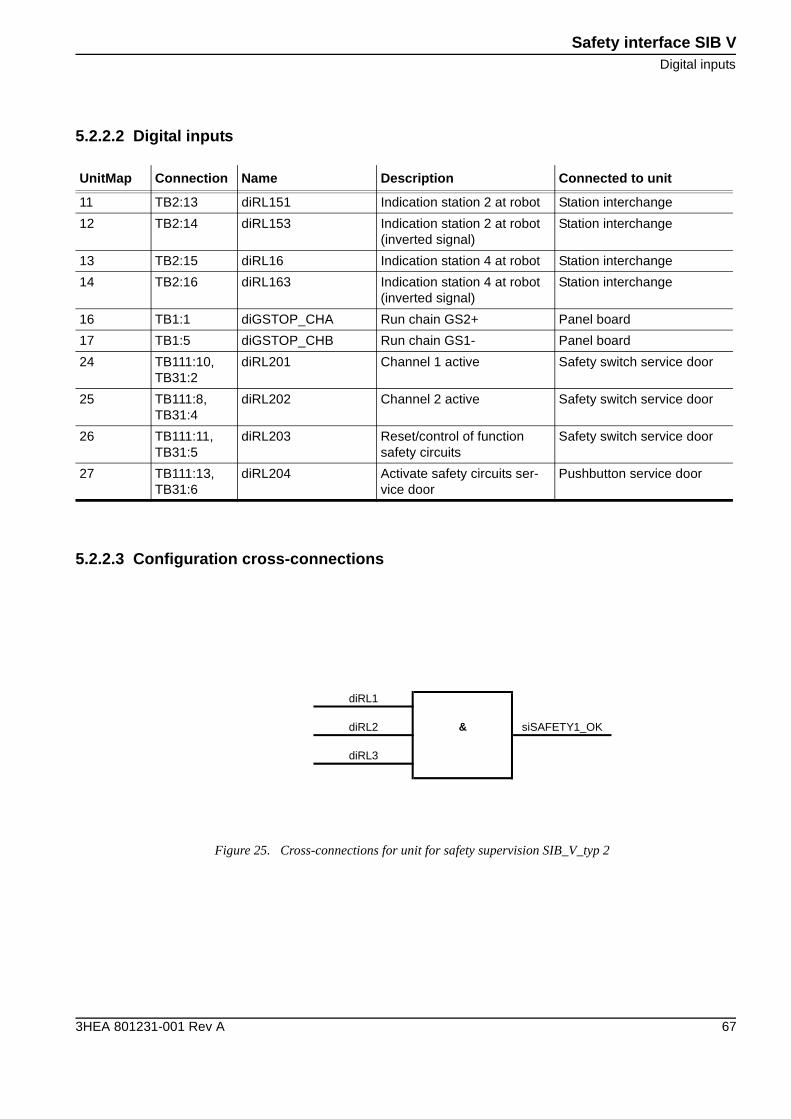
Figure 25. Cross-connections for unit for safety supervision SIB_V_typ 2
diRL1
diRL2 & siSAFETY1_OK
diRL3
Safety interface SIB V
Positioner A/L/S
68 3HEA 801231-001 Rev A
5.3 Positioner A/L/S
5.3.1 I/O board Configuration SIB V
Exemple
1
Address Name Board typeDigitalinputs
Digitaloutputs
8 SIB_V_B1 Safety Interface Board Type 1 56 -
9* SIB_V_B1 Safety Interface Board Type 1 56 -
8 SIB_V_B2 Safety Interface Board Type 2 56 -
9* SIB_V_B2 Safety Interface Board Type 2 56 -
8 SIB_V_B3 Safety Interface Board Type 3 56 -
9* SIB_V_B3 Safety Interface Board Type 3 56 -
*) Used as board No 2 in multi-stations applications or combinations between different types of positioners.Example: Robot weldihng station with one positioner type IRBP 250K and one positioner type IRBP 250L.
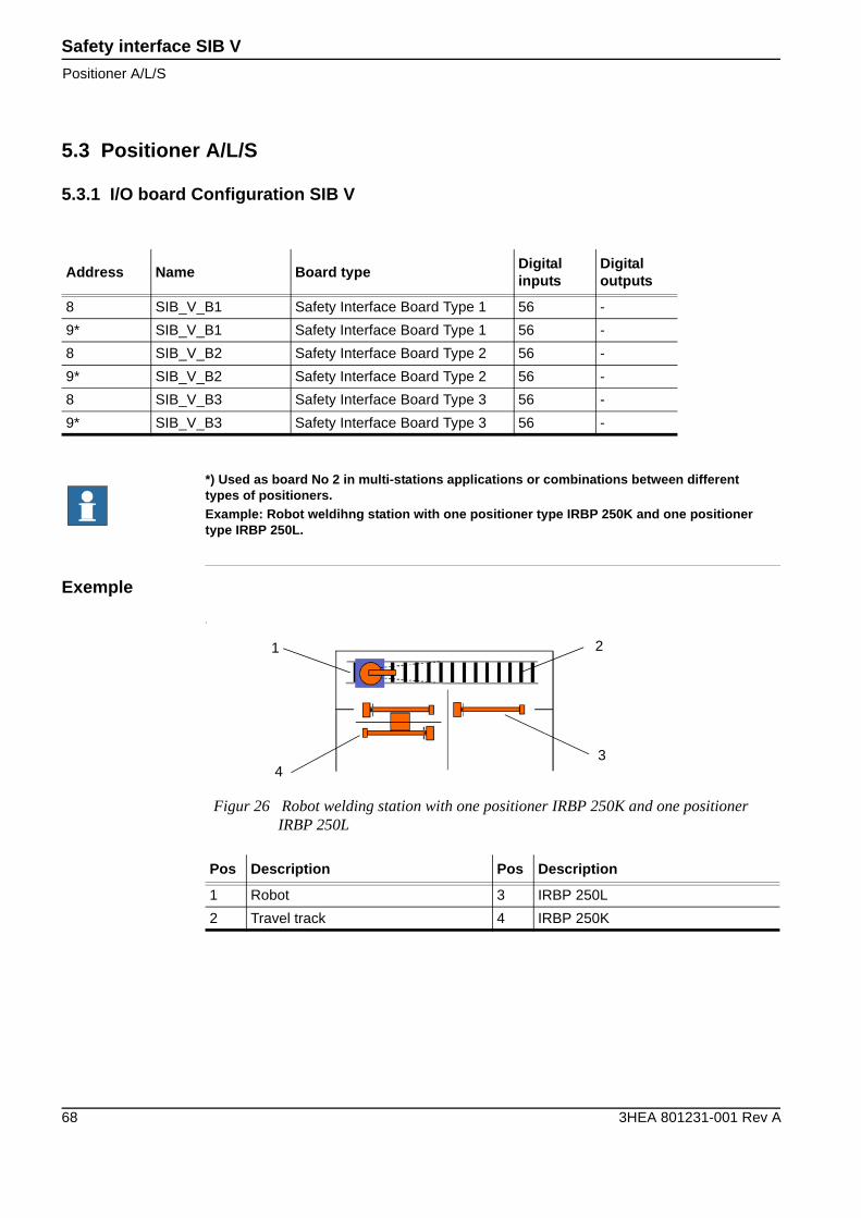
Figur 26 Robot welding station with one positioner IRBP 250K and one positioner IRBP 250L
Pos Description Pos Description
1 Robot 3 IRBP 250L
2 Travel track 4 IRBP 250K
1
4
2
3
Safety interface SIB VDigital inputs
3HEA 801231-001 Rev A 69
5.3.2 I/O-signal configuration for SIB_V_B3
5.3.2.1 Digital inputs
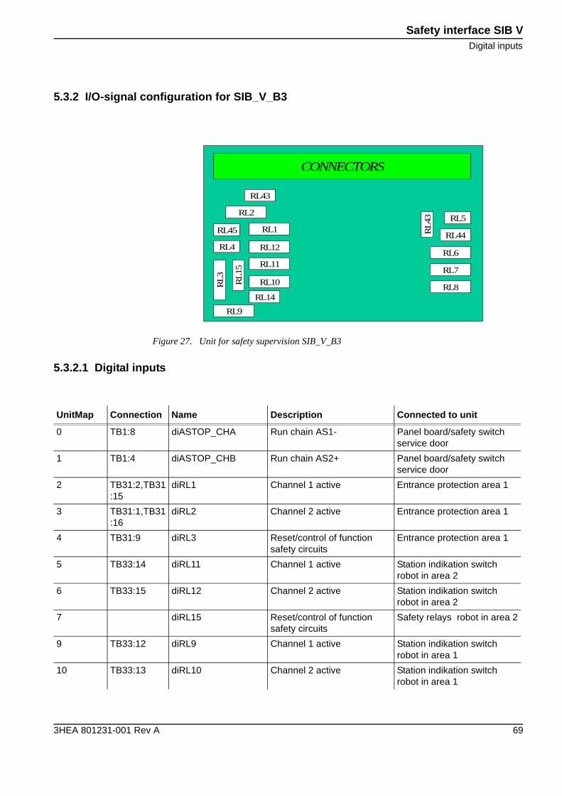
Figure 27. Unit for safety supervision SIB_V_B3
RL9
RL10
RL11
RL4
RL45
RL8RL14
RL5
RL
43
RL7
RL2
RL43
CONNECTORS
RL
3
RL
15RL12
RL1
RL6
RL44
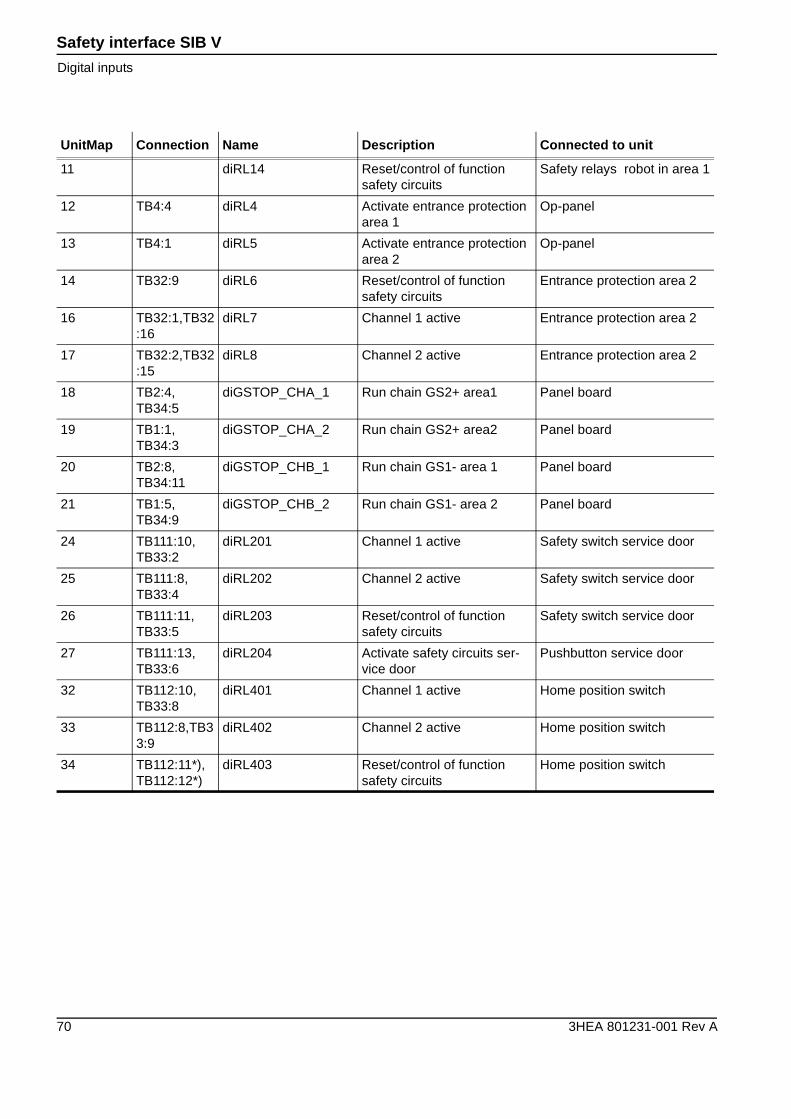
UnitMap Connection Name Description Connected to unit
0 TB1:8 diASTOP_CHA Run chain AS1- Panel board/safety switch service door
1 TB1:4 diASTOP_CHB Run chain AS2+ Panel board/safety switch service door
2 TB31:2,TB31:15
diRL1 Channel 1 active Entrance protection area 1
3 TB31:1,TB31:16
diRL2 Channel 2 active Entrance protection area 1
4 TB31:9 diRL3 Reset/control of function safety circuits
Entrance protection area 1
5 TB33:14 diRL11 Channel 1 active Station indikation switch robot in area 2
6 TB33:15 diRL12 Channel 2 active Station indikation switch robot in area 2
7 diRL15 Reset/control of function safety circuits
Safety relays robot in area 2
9 TB33:12 diRL9 Channel 1 active Station indikation switch robot in area 1
10 TB33:13 diRL10 Channel 2 active Station indikation switch robot in area 1
Safety interface SIB V
Digital inputs
70 3HEA 801231-001 Rev A
11 diRL14 Reset/control of function safety circuits
Safety relays robot in area 1
12 TB4:4 diRL4 Activate entrance protection area 1
Op-panel
13 TB4:1 diRL5 Activate entrance protection area 2
Op-panel
14 TB32:9 diRL6 Reset/control of function safety circuits
Entrance protection area 2
16 TB32:1,TB32:16
diRL7 Channel 1 active Entrance protection area 2
17 TB32:2,TB32:15
diRL8 Channel 2 active Entrance protection area 2
18 TB2:4, TB34:5
diGSTOP_CHA_1 Run chain GS2+ area1 Panel board
19 TB1:1, TB34:3
diGSTOP_CHA_2 Run chain GS2+ area2 Panel board
20 TB2:8, TB34:11
diGSTOP_CHB_1 Run chain GS1- area 1 Panel board
21 TB1:5, TB34:9
diGSTOP_CHB_2 Run chain GS1- area 2 Panel board
24 TB111:10, TB33:2
diRL201 Channel 1 active Safety switch service door
25 TB111:8, TB33:4
diRL202 Channel 2 active Safety switch service door
26 TB111:11, TB33:5
diRL203 Reset/control of function safety circuits
Safety switch service door
27 TB111:13, TB33:6
diRL204 Activate safety circuits ser-vice door
Pushbutton service door
32 TB112:10, TB33:8
diRL401 Channel 1 active Home position switch
33 TB112:8,TB33:9
diRL402 Channel 2 active Home position switch
34 TB112:11*), TB112:12*)
diRL403 Reset/control of function safety circuits
Home position switch
UnitMap Connection Name Description Connected to unit
Safety interface SIB VConfiguration cross-connections
3HEA 801231-001 Rev A 71
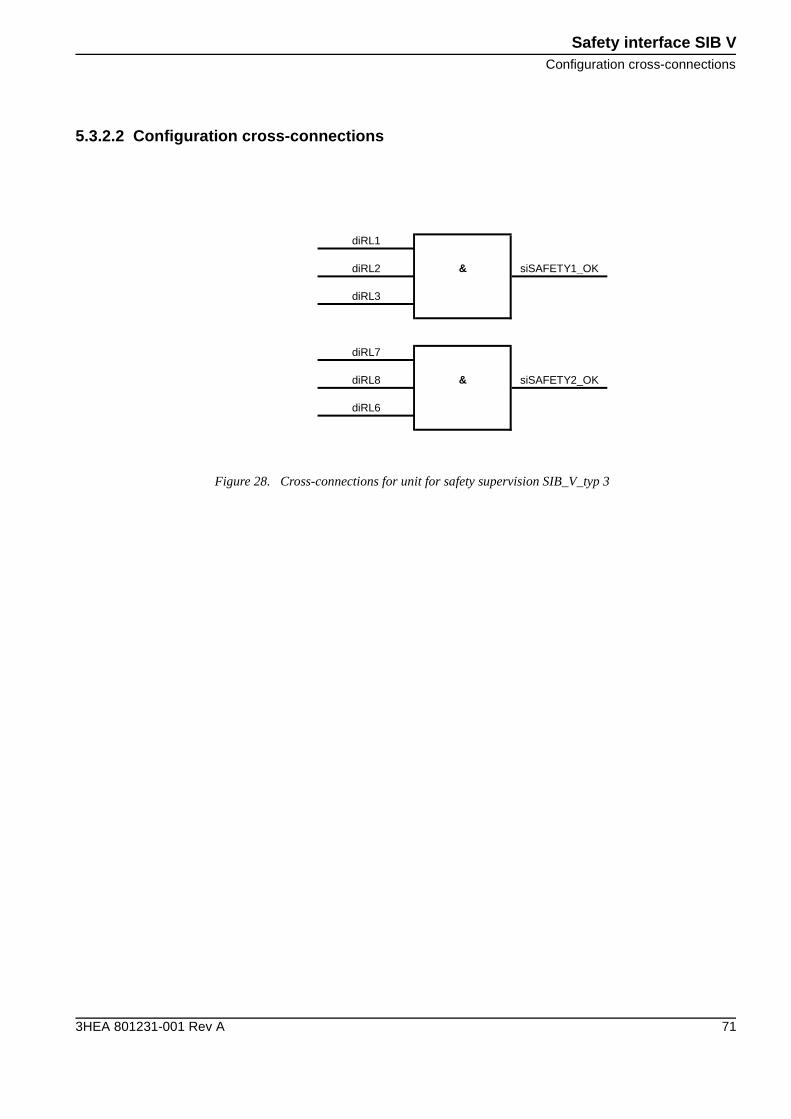
5.3.2.2 Configuration cross-connections
Figure 28. Cross-connections for unit for safety supervision SIB_V_typ 3
diRL1
diRL2 & siSAFETY1_OK
diRL3
diRL7
diRL8 & siSAFETY2_OK
diRL6
Safety interface SIB V
Configuration cross-connections
72 3HEA 801231-001 Rev A


3HEA 801231-001 Rev A
���