Embed Size (px)
Citation preview
Arc Welding Processes for AdditiveManufacturing: A Review
Zengxi Pan, Donghong Ding(&), Bintao Wu, Dominic Cuiuri,Huijun Li, and John Norrish
Faculty of Engineering and Information Science, School of Mechanical,Materials, and Mechatronics Engineering, University of Wollongong,
Northfield Ave, Wollongong, NSW 2500, [email protected]
Abstract. Arc-welding based additive manufacturing techniques are attractinginterest from the manufacturing industry because of their potential to fabricatelarge metal components with low cost and short production lead time. Thispaper introduces wire arc additive manufacturing (WAAM) techniques, reviewsmechanical properties of additively manufactured metallic components, sum-marises the development in process planning, sensing and control of WAAM,and finally provides recommendations for future work. Research indicates thatthe mechanical properties of additively manufactured materials, such as titaniumalloy, are comparable to cast or wrought material. It has also been found thattwin-wire WAAM has the capability to fabricate intermetallic alloys andfunctional graded materials. The paper concludes that WAAM is a promisingalternative to traditional subtractive manufacturing for fabricating large expen-sive metal components. On the basis of current trends, the future outlook willinclude automated process planning, monitoring, and control for WAAMprocess.
Keywords: Arc welding � Additive manufacturing � Review � Materials �Automation � Control
1 Introduction
Arc welding has been widely explored for additive manufacturing (AM) of large metalcomponents over the last three decades due to its lower capital investment, an unlimitedbuild envelope, and higher deposition rates [1]. The concept of using arc welding as ameans of building up components was initiated in the 1990s from Europe [2, 3]. Thecapability of arc welding has been demonstrated through building several prototypeparts with good structural integrity and mechanical properties [4]. However, WAAMreceived less attention than other AM processes at that time due to a few reasons:(1) High heat input associated with welding processes can induce residual stress as wellas part distortion [5]; (2) Poor accuracy (about ±0.2 mm) and surface finish of thefabricated part are unacceptable for many applications [1]; (3) Solid layers cannot befilled to form a smooth surface, resulting in inner gaps or voids [6]; (4) AutomatedCAD-to-part AM system using arc welding processes is immature [7]; (5) Lack of
© Springer Nature Singapore Pte Ltd. 2018S. Chen et al. (eds.), Transactions on Intelligent Welding Manufacturing,Transactions on Intelligent Welding Manufacturing, DOI 10.1007/978-981-10-5355-9_1
integrated, reliable process monitoring and control to accommodate variations duringthe deposition.
More recently, there has been increasing interest in applying AM to titanium alloysdue to greater demand for titanium alloys in the aerospace industry, and the difficultyand inefficiency of subtractive manufacturing from billet. There are several alternativeapproaches including laser [8] and electron beam AM systems [9]. At CranfieldUniversity [10] in UK and University of Wollongong [11] in Australia efforts havebeen focused on the use of the wire arc additive manufacturing (WAAM) processes dueto their high deposition rate, unlimited build envelop, and efficient use of materials,which provide advantages for fabricating medium to large sized components. Over thelast ten years, the WAAM process has attracted significant interest, with the search term“wire arc additive manufacturing” being mentioned in 536 documents in the 2017Scopus database. Many important facets of WAAM have been widely investigated,including processes and machines, materials, path design and programming, processmodelling and online control [12]. A review of WAAM technologies is thereforeessential for researchers in this area, to summarize the state-of-the-art research out-comes and also to point out the future research interests. A number of existing literaturereviews on AM from various aspects can be found [1, 13–20].
This article places emphasis particularly on WAAM technologies, provides ageneral overview of the most commonly available WAAM processes, lists themechanical properties of the processed metallic materials as found in the literature, anddescribes recent development on process planning, sensing and control. The paper endswith conclusions and future research perspective.
2 Wire Arc Additive Manufacturing Systems
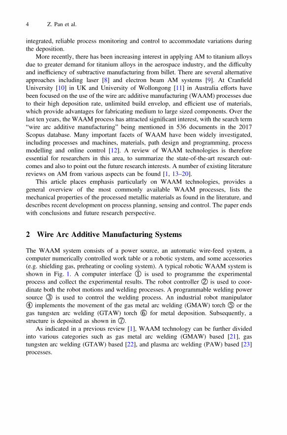
The WAAM system consists of a power source, an automatic wire-feed system, acomputer numerically controlled work table or a robotic system, and some accessories(e.g. shielding gas, preheating or cooling system). A typical robotic WAAM system isshown in Fig. 1. A computer interface ① is used to programme the experimentalprocess and collect the experimental results. The robot controller ② is used to coor-dinate both the robot motions and welding processes. A programmable welding powersource ③ is used to control the welding process. An industrial robot manipulator④ implements the movement of the gas metal arc welding (GMAW) torch ⑤ or thegas tungsten arc welding (GTAW) torch ⑥ for metal deposition. Subsequently, astructure is deposited as shown in ⑦.
As indicated in a previous review [1], WAAM technology can be further dividedinto various categories such as gas metal arc welding (GMAW) based [21], gastungsten arc welding (GTAW) based [22], and plasma arc welding (PAW) based [23]processes.
4 Z. Pan et al.
2.1 GMAW-Based WAAM Systems
GMAW is a welding process in which an electric arc forms between a consumable wireelectrode and the workpiece metal. The wire is usually perpendicular to the substrate.For a single-wire process, there is no limitation imposed on movement during depo-sition by the need to rotate the torch. Various transfer modes can be used in GMAW,such as spray and pulsed-spray. Cold metal transfer (CMT), as a modified GMAWvariant based on the controlled dip transfer mode, has been widely used for WAAMdue to its high deposition rate with low heat input [24]. Tandem GMAW, a twin-wireprocess, was recently reported for creating metallic objects with high deposition rates[25], as shown in Fig. 2. Although it has been stated that the tandem system has thepotential to produce intermetallic alloy as well as the gradient materials, to date thereare no reports of this in the literature. To increase the deposition rate and materialefficiency, a double electrode GMAW using GTAW torch to provide the bypass currentwas developed as shown in Fig. 3. It was reported that the coefficient of materialsutilization increased more than 10% using DE-GMAW for depositing thin-wall partswithin a certain range of bypass current [26]. Note that for any wire-arc system withmore than one electrode or wire, the torch must be aligned with the direction of travel,imposing a significant additional constraint on the path planning algorithm.
2.2 GTAW-Based WAAM Systems
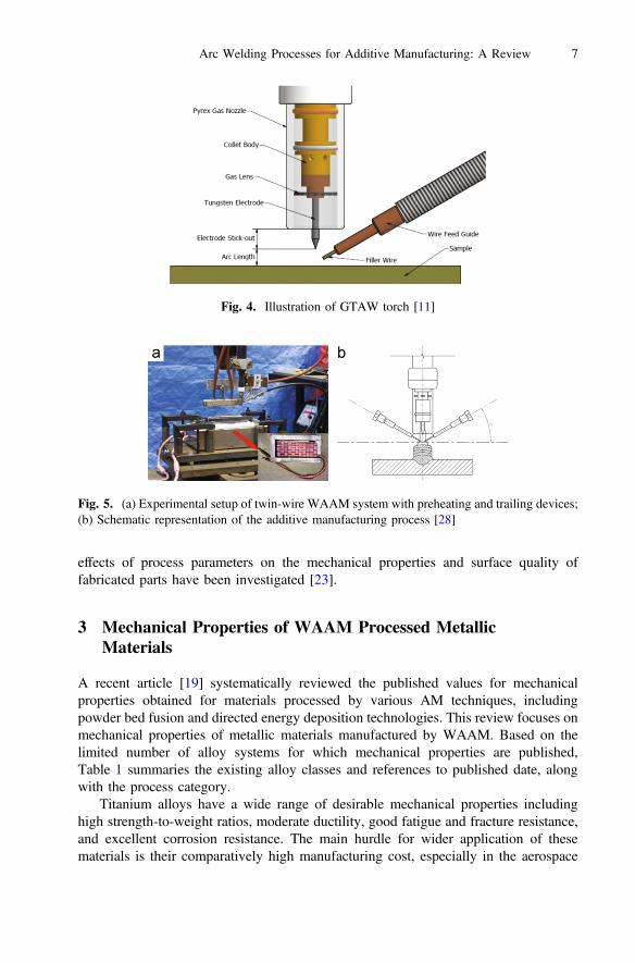
GTAW uses a non-consumable tungsten electrode in combination with a separately-fedwire to produce the weld deposit, as shown in Fig. 4. During the deposition process,wire feed orientation influences material transfer and the quality for the deposit. Backfeeding, side feeding, and front feeding can be used. Front feeding is normallyimplemented for Ti-based and Fe-based AM. A mathematical model has been devel-oped to optimise the wire feed direction and position for improved deposition accuracy[27]. Increasing arc length was accompanied by an equal increase in the distancebetween the shielding nozzle and the workpiece. A gas lens is used to generate laminar
Fig. 1. Schematic diagram of the developed experimental WAAM system
Arc Welding Processes for Additive Manufacturing: A Review 5

flow of shielding gas to reduce oxidation. A trailing shielding device is usually used toprevent oxidation during the WAAM of titanium alloys on open air [11].
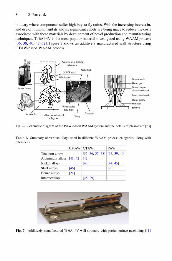
Twin-wire GTAW-based WAAM has been developed to produce intermetallic andfunctionally graded materials [28–30]. Two different wires from separate wire-feedsystems are fed into a single melt pool to form objects. The composition of differentmaterials can be controlled through separately adjusting the wire-feed rates. Preheatingand trailing gas shielding may be used to control the inter pass temperature and toprevent oxidation, respectively. An experimental setup of twin-wire WAAM and theschematic diagram of the manufacturing process are shown in Fig. 5.
2.3 PAW-Based WAAM System
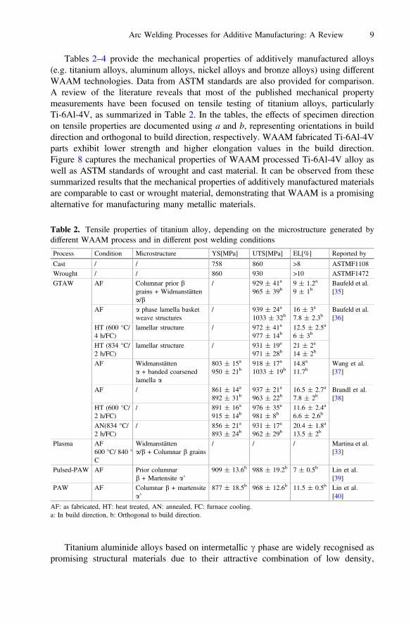
PAW as a method for the AM of metallic materials has also been widely investigated[31–33]. Arc energy density in plasma welding can reach three times that of GTAW,causing less weld distortion and smaller welds with higher welding speeds [34].A micro-PAW based WAAM system, as shown in Fig. 6, was introduced and the
Fig. 2. Schematic of twin-wire welding torch for WAAM [25]
Fig. 3. Schematic diagram of double electrode GMAW-based AM system [26]
6 Z. Pan et al.
effects of process parameters on the mechanical properties and surface quality offabricated parts have been investigated [23].
3 Mechanical Properties of WAAM Processed MetallicMaterials
A recent article [19] systematically reviewed the published values for mechanicalproperties obtained for materials processed by various AM techniques, includingpowder bed fusion and directed energy deposition technologies. This review focuses onmechanical properties of metallic materials manufactured by WAAM. Based on thelimited number of alloy systems for which mechanical properties are published,Table 1 summaries the existing alloy classes and references to published date, alongwith the process category.
Titanium alloys have a wide range of desirable mechanical properties includinghigh strength-to-weight ratios, moderate ductility, good fatigue and fracture resistance,and excellent corrosion resistance. The main hurdle for wider application of thesematerials is their comparatively high manufacturing cost, especially in the aerospace
Fig. 4. Illustration of GTAW torch [11]
Fig. 5. (a) Experimental setup of twin-wire WAAM system with preheating and trailing devices;(b) Schematic representation of the additive manufacturing process [28]
Arc Welding Processes for Additive Manufacturing: A Review 7
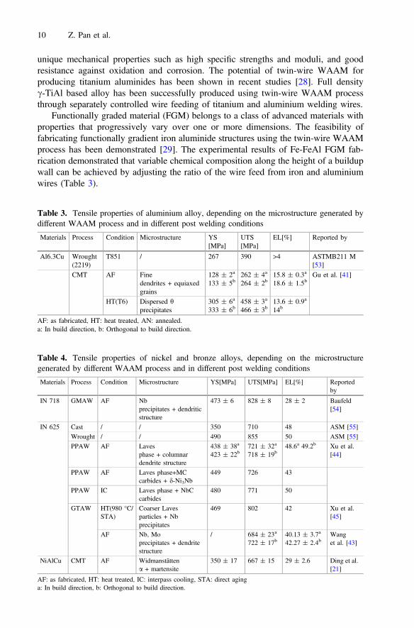
industry where components suffer high buy-to-fly ratios. With the increasing interest in,and use of, titanium and its alloys, significant efforts are being made to reduce the costsassociated with these materials by development of novel production and manufacturingtechniques. Ti-6Al-4V is the most popular material investigated using WAAM process[36, 38, 40, 47–52]. Figure 7 shows an additively manufactured wall structure usingGTAW-based WAAM process.
Fig. 6. Schematic diagram of the PAW-based WAAM system and the details of plasma arc [23]
Table 1. Summary of various alloys used in different WAAM process categories, along withreferences
GMAW GTAW PAW
Titanium alloys [35, 36, 37, 38] [33, 39, 40]Aluminium alloys [41, 42] [42]Nickel alloys [43] [44, 45]Steel alloys [46] [23]Bonze alloys [21]Intermetallics [28, 29]
Fig. 7. Additively manufactured Ti-6Al-4V wall structure with partial surface machining [11]
8 Z. Pan et al.
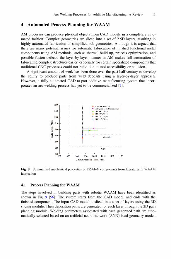
Tables 2–4 provide the mechanical properties of additively manufactured alloys(e.g. titanium alloys, aluminum alloys, nickel alloys and bronze alloys) using differentWAAM technologies. Data from ASTM standards are also provided for comparison.A review of the literature reveals that most of the published mechanical propertymeasurements have been focused on tensile testing of titanium alloys, particularlyTi-6Al-4V, as summarized in Table 2. In the tables, the effects of specimen directionon tensile properties are documented using a and b, representing orientations in builddirection and orthogonal to build direction, respectively. WAAM fabricated Ti-6Al-4Vparts exhibit lower strength and higher elongation values in the build direction.Figure 8 captures the mechanical properties of WAAM processed Ti-6Al-4V alloy aswell as ASTM standards of wrought and cast material. It can be observed from thesesummarized results that the mechanical properties of additively manufactured materialsare comparable to cast or wrought material, demonstrating that WAAM is a promisingalternative for manufacturing many metallic materials.
Titanium aluminide alloys based on intermetallic c phase are widely recognised aspromising structural materials due to their attractive combination of low density,
Table 2. Tensile properties of titanium alloy, depending on the microstructure generated bydifferent WAAM process and in different post welding conditions
Process Condition Microstructure YS[MPa] UTS[MPa] EL[%] Reported by
Cast / / 758 860 >8 ASTMF1108Wrought / / 860 930 >10 ASTMF1472GTAW AF Columnar prior b
grains + Widmanstättena/b
/ 929 ± 41a
965 ± 39b9 ± 1.2a
9 ± 1bBaufeld et al.[35]
AF a phase lamella basketweave structures
/ 939 ± 24a
1033 ± 32b16 ± 3a
7.8 ± 2.3bBaufeld et al.[36]
HT (600 °C/4 h/FC)
lamellar structure / 972 ± 41a
977 ± 14b12.5 ± 2.5a
6 ± 3b
HT (834 °C/2 h/FC)
lamellar structure / 931 ± 19a
971 ± 28b21 ± 2a
14 ± 2b
AF Widmanstättena + banded coarsenedlamella a
803 ± 15a
950 ± 21b918 ± 17a
1033 ± 19b14.8a
11.7bWang et al.[37]
AF / 861 ± 14a
892 ± 31b937 ± 21a
963 ± 22b16.5 ± 2.7a
7.8 ± 2bBrandl et al.[38]
HT (600 °C/2 h/FC)
/ 891 ± 16a
915 ± 14b976 ± 35a
981 ± 8b11.6 ± 2.4a
6.6 ± 2.6b
AN(834 °C/2 h/FC)
/ 856 ± 21a
893 ± 24b931 ± 17a
962 ± 29b20.4 ± 1.8a
13.5 ± 2b
Plasma AF600 °C/ 840 °C
Widmanstättena/b + Columnar b grains
/ / / Martina et al.[33]
Pulsed-PAW AF Prior columnarb + Martensite a’
909 ± 13.6b 988 ± 19.2b 7 ± 0.5b Lin et al.[39]
PAW AF Columnar b + martensitea’
877 ± 18.5b 968 ± 12.6b 11.5 ± 0.5b Lin et al.[40]
AF: as fabricated, HT: heat treated, AN: annealed, FC: furnace cooling.a: In build direction, b: Orthogonal to build direction.
Arc Welding Processes for Additive Manufacturing: A Review 9
unique mechanical properties such as high specific strengths and moduli, and goodresistance against oxidation and corrosion. The potential of twin-wire WAAM forproducing titanium aluminides has been shown in recent studies [28]. Full densityc-TiAl based alloy has been successfully produced using twin-wire WAAM processthrough separately controlled wire feeding of titanium and aluminium welding wires.
Functionally graded material (FGM) belongs to a class of advanced materials withproperties that progressively vary over one or more dimensions. The feasibility offabricating functionally gradient iron aluminide structures using the twin-wire WAAMprocess has been demonstrated [29]. The experimental results of Fe-FeAl FGM fab-rication demonstrated that variable chemical composition along the height of a buildupwall can be achieved by adjusting the ratio of the wire feed from iron and aluminiumwires (Table 3).
Table 3. Tensile properties of aluminium alloy, depending on the microstructure generated bydifferent WAAM process and in different post welding conditions
Materials Process Condition Microstructure YS[MPa]
UTS[MPa]
EL[%] Reported by
Al6.3Cu Wrought(2219)
T851 / 267 390 >4 ASTMB211 M[53]
CMT AF Finedendrites + equiaxedgrains
128 ± 2a
133 ± 5b262 ± 4a
264 ± 2b15.8 ± 0.3a
18.6 ± 1.5bGu et al. [41]
HT(T6) Dispersed hprecipitates
305 ± 6a
333 ± 6b458 ± 3a
466 ± 3b13.6 ± 0.9a
14b
AF: as fabricated, HT: heat treated, AN: annealed.a: In build direction, b: Orthogonal to build direction.
Table 4. Tensile properties of nickel and bronze alloys, depending on the microstructuregenerated by different WAAM process and in different post welding conditions
Materials Process Condition Microstructure YS[MPa] UTS[MPa] EL[%] Reportedby
IN 718 GMAW AF Nbprecipitates + dendriticstructure
473 ± 6 828 ± 8 28 ± 2 Baufeld[54]
IN 625 Cast / / 350 710 48 ASM [55]Wrought / / 490 855 50 ASM [55]PPAW AF Laves
phase + columnardendrite structure
438 ± 38a
423 ± 22b721 ± 32a
718 ± 19b48.6a 49.2b Xu et al.
[44]
PPAW AF Laves phase+MCcarbides + d-Ni3Nb
449 726 43
PPAW IC Laves phase + NbCcarbides
480 771 50
GTAW HT(980 °C/STA)
Coarser Lavesparticles + Nbprecipitates
469 802 42 Xu et al.[45]
AF Nb, Moprecipitates + dendritestructure
/ 684 ± 23a
722 ± 17b40.13 ± 3.7a
42.27 ± 2.4bWanget al. [43]
NiAlCu CMT AF Widmanstättena + martensite
350 ± 17 667 ± 15 29 ± 2.6 Ding et al.[21]
AF: as fabricated, HT: heat treated, IC: interpass cooling, STA: direct aginga: In build direction, b: Orthogonal to build direction.
10 Z. Pan et al.
4 Automated Process Planning for WAAM
AM processes can produce physical objects from CAD models in a completely auto-mated fashion. Complex geometries are sliced into a set of 2.5D layers, resulting inhighly automated fabrication of simplified sub-geometries. Although it is argued thatthere are many potential issues for automatic fabrication of finished functional metalcomponents using AM methods, such as thermal build up, process optimization, andpossible fusion defects, the layer-by-layer manner in AM makes full automation offabricating complex structures easier, especially for certain specialized components thattraditional CNC processes could not build due to tool accessibility or collision.
A significant amount of work has been done over the past half century to developthe ability to produce parts from weld deposits using a layer-by-layer approach.However, a fully automated CAD-to-part additive manufacturing system that incor-porates an arc welding process has yet to be commercialized [7].
4.1 Process Planning for WAAM
The steps involved in building parts with robotic WAAM have been identified asshown in Fig. 9 [56]. The system starts from the CAD model, and ends with thefinished component. The input CAD model is sliced into a set of layers using the 3Dslicing module. Then deposition paths are generated for each layer through the 2D pathplanning module. Welding parameters associated with each generated path are auto-matically selected based on an artificial neural network (ANN) bead geometry model.
Fig. 8. Summarized mechanical properties of Ti6Al4V components from literatures in WAAMfabrication
Arc Welding Processes for Additive Manufacturing: A Review 11
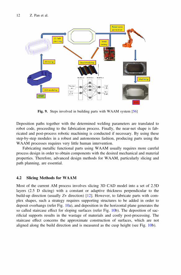
Deposition paths together with the determined welding parameters are translated torobot code, proceeding to the fabrication process. Finally, the near-net shape is fab-ricated and post-process robotic machining is conducted if necessary. By using thesestep-by-step modules in a robust and autonomous fashion, producing parts using theWAAM processes requires very little human intervention.
Fabricating metallic functional parts using WAAM usually requires more carefulprocess design in order to obtain components with the desired mechanical and materialproperties. Therefore, advanced design methods for WAAM, particularly slicing andpath planning, are essential.
4.2 Slicing Methods for WAAM
Most of the current AM process involves slicing 3D CAD model into a set of 2.5Dlayers (2.5 D slicing) with a constant or adaptive thickness perpendicular to thebuild-up direction (usually Z+ direction) [12]. However, to fabricate parts with com-plex shapes, such a strategy requires supporting structures to be added in order todeposit overhangs (refer Fig. 10a), and deposition in the horizontal plane generates theso called staircase effect for sloping surfaces (refer Fig. 10b). The deposition of sac-rificial supports results in the wastage of materials and costly post-processing. Thestaircase effect concerns the approximate construction of surfaces, which are notaligned along the build direction and is measured as the cusp height (see Fig. 10b).
Fig. 9. Steps involved in building parts with WAAM system [56]
12 Z. Pan et al.
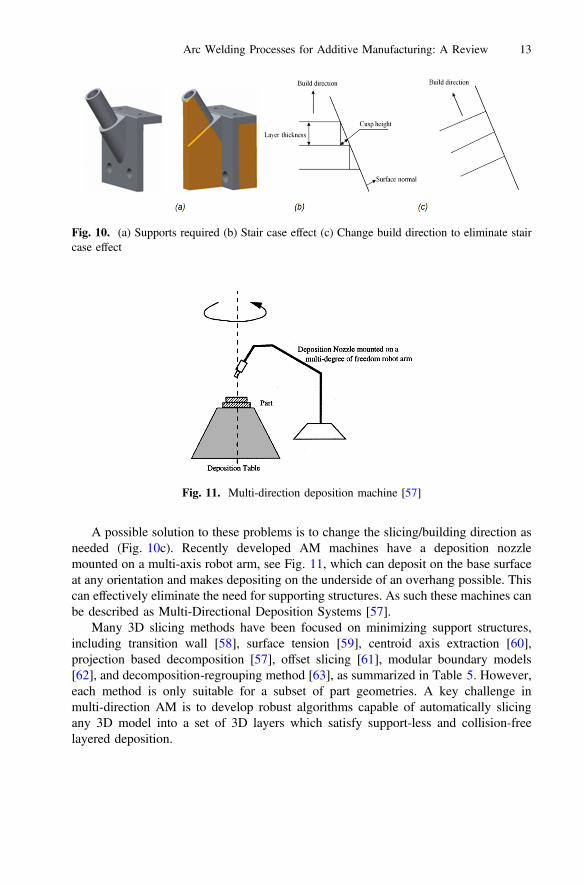
A possible solution to these problems is to change the slicing/building direction asneeded (Fig. 10c). Recently developed AM machines have a deposition nozzlemounted on a multi-axis robot arm, see Fig. 11, which can deposit on the base surfaceat any orientation and makes depositing on the underside of an overhang possible. Thiscan effectively eliminate the need for supporting structures. As such these machines canbe described as Multi-Directional Deposition Systems [57].
Many 3D slicing methods have been focused on minimizing support structures,including transition wall [58], surface tension [59], centroid axis extraction [60],projection based decomposition [57], offset slicing [61], modular boundary models[62], and decomposition-regrouping method [63], as summarized in Table 5. However,each method is only suitable for a subset of part geometries. A key challenge inmulti-direction AM is to develop robust algorithms capable of automatically slicingany 3D model into a set of 3D layers which satisfy support-less and collision-freelayered deposition.
Fig. 10. (a) Supports required (b) Stair case effect (c) Change build direction to eliminate staircase effect
Fig. 11. Multi-direction deposition machine [57]
Arc Welding Processes for Additive Manufacturing: A Review 13
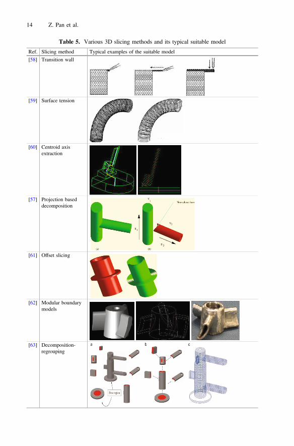
Table 5. Various 3D slicing methods and its typical suitable model
Ref. Slicing method Typical examples of the suitable model
[58] Transition wall
[59] Surface tension
[60] Centroid axisextraction
[57] Projection baseddecomposition
[61] Offset slicing
[62] Modular boundarymodels
[63] Decomposition-regrouping
14 Z. Pan et al.
4.3 Path Planning Strategies for WAAM
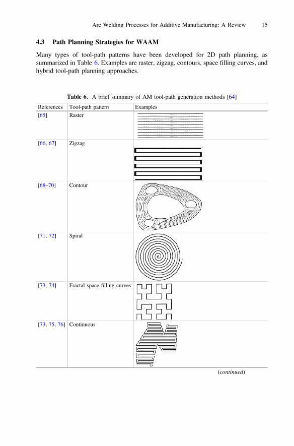
Many types of tool-path patterns have been developed for 2D path planning, assummarized in Table 6. Examples are raster, zigzag, contours, space filling curves, andhybrid tool-path planning approaches.
Table 6. A brief summary of AM tool-path generation methods [64]
References Tool-path pattern Examples
[65] Raster
[66, 67] Zigzag
[68–70] Contour
[71, 72] Spiral
[73, 74] Fractal space filling curves
[73, 75, 76] Continuous
(continued)
Arc Welding Processes for Additive Manufacturing: A Review 15
Transferring these path planning strategies to a WAAM system is not a straight-forward task since the two processes are dissimilar in many ways. The raster scanningpath technique is based on planar ray casting along one direction [65]. Derived from theraster strategy, zigzag tool-path generation is the most popular method used in com-mercial AM systems. While it fills geometries line-by-line along one direction like theraster approach, the zigzag approach combines the separate parallel lines into a singlecontinuous pass which significantly reduces the number of tool-path passes [66, 67].However, the outline accuracy of the part for both raster and zigzag approaches is poordue to the discretization errors on any edge that is not parallel to the tool motiondirection. Contour path generation, which is another typical method, can address thisgeometrical quality issue effectively by following the geometrical trend of the boundarycontours [68, 69]. However, by offsetting the contours, the scheme generates numerousclosed curves. The spiral tool-path generation is widely applied in numerically con-trolled (NC) machining, but is only suitable for certain special geometrical models inthe AM process [79]. Another tool-path planning method is based on fractal spacefilling curves. Bertoldi et al. [73] applied Hilbert curve-based tool-paths to the FusedDeposition Modelling process. However, the large numbers of path direction turningmotions that are produced in this strategy are not suitable for wire-feed AM. Contin-uous path planning can be considered as another tool-path generation method. Thismethod is able to generate filling patterns that allow continuous deposition in a singlepath to fill any arbitrarily shaped area. The number of welding passes is reducedsignificantly, thereby minimizing starting-stopping sequences, which is advantageousfor the wire-feed AM process. The hybrid path planning strategy is also promising as itshares some merits of various approaches. Generally, a combination of contour and
Table 6. (continued)
References Tool-path pattern Examples
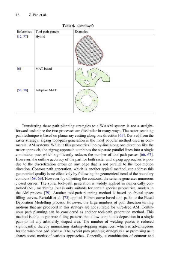
[12, 77] Hybrid
[6] MAT-based
[56, 78] Adaptive MAT
16 Z. Pan et al.
zigzag pattern is commonly developed to meet both the geometrical accuracy and buildefficiency requirements [12, 77]. Reference [6] proposed an innovative path planningstrategy, called Medial Axis Transformation (MAT) path, which allows the system todeposit material from the inside towards the outside of a given part geometry. Usingthis MAT path routine for wire arc additive manufacturing, gaps or voids can beavoided or significantly reduced. As a result, fully dense metal components can beachieved with high productivity and low cost. Based on this “basic” MAT path routine,further studies [56, 78] have proposed adaptive MAT paths to further improve geo-metrical accuracy and produce void-free deposition. This technique involves continu-ously altering the deposition width of the wire-feed process to accommodate thecomponent geometry, while simultaneously minimising the number of interruptions tothe deposition process at the component boundary. Adaptive MAT-based path planningstrategy is particularly benefit for the WAAM of thin-walled structures.
To date, the path planning for WAAM remains empirical and some humaninvention is required. Depending on the characteristics of the 2D geometries, however,different tool-path patterns are needed.
5 Sensing and Control of WAAM
Current implementations of WAAM through automated process planning areopen-loop processes, and the quality of the produced parts relies significantly on theaccuracy of the knowledge-based process models (e.g. artificial neural network beadmodelling and overlapping model). However, process stability and repeatability areextremely sensitive to the process parameters, building sequences, and welding dis-turbances. Therefore, to assure desired quality of the deposited parts, sensing andcontrol of the WAAM process is of great importance.
Sensing and control of WAAM is still at a very early stage, and single-bead wallbuilding was a commonly used case study. The main task is to maintain or control thewidth and the height of the wall using various sensing and control strategies [80–82].This section reviews the recent developments in sensing technology for the WAAM orarc welding processes.
On-line measurement of the width of the building wall or weld pool is an essentialstep for control of the process. Visual sensing has commonly been used for qualitycontrol of arc welding process, since it has the potential to directly provide dimensionalinformation of weld pool [83]. There were two classes of visual sensing system, namelyactive visual sensing and passive vision sensing.
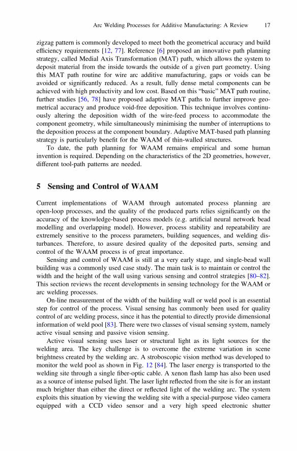
Active visual sensing uses laser or structural light as its light sources for thewelding area. The key challenge is to overcome the extreme variation in scenebrightness created by the welding arc. A stroboscopic vision method was developed tomonitor the weld pool as shown in Fig. 12 [84]. The laser energy is transported to thewelding site through a single fiber-optic cable. A xenon flash lamp has also been usedas a source of intense pulsed light. The laser light reflected from the site is for an instantmuch brighter than either the direct or reflected light of the welding arc. The systemexploits this situation by viewing the welding site with a special-purpose video cameraequipped with a CCD video sensor and a very high speed electronic shutter
Arc Welding Processes for Additive Manufacturing: A Review 17
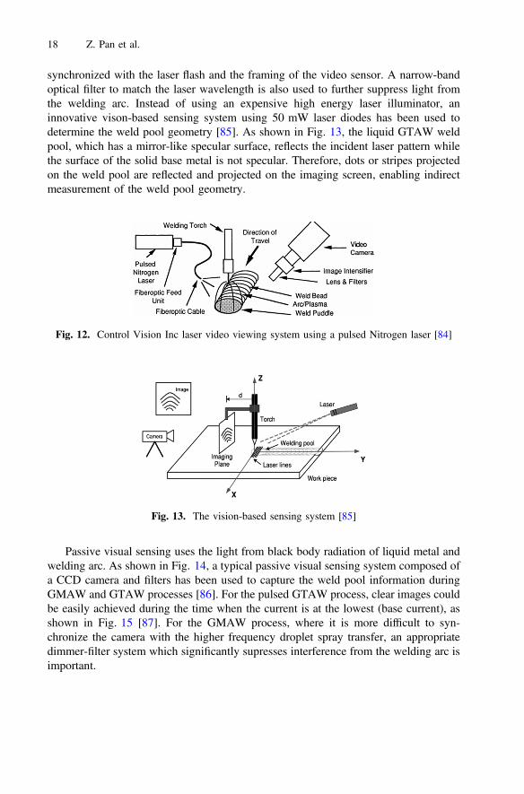
synchronized with the laser flash and the framing of the video sensor. A narrow-bandoptical filter to match the laser wavelength is also used to further suppress light fromthe welding arc. Instead of using an expensive high energy laser illuminator, aninnovative vison-based sensing system using 50 mW laser diodes has been used todetermine the weld pool geometry [85]. As shown in Fig. 13, the liquid GTAW weldpool, which has a mirror-like specular surface, reflects the incident laser pattern whilethe surface of the solid base metal is not specular. Therefore, dots or stripes projectedon the weld pool are reflected and projected on the imaging screen, enabling indirectmeasurement of the weld pool geometry.
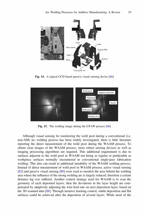
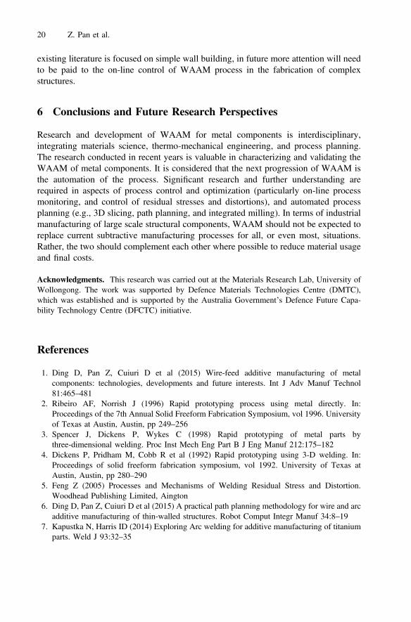
Passive visual sensing uses the light from black body radiation of liquid metal andwelding arc. As shown in Fig. 14, a typical passive visual sensing system composed ofa CCD camera and filters has been used to capture the weld pool information duringGMAW and GTAW processes [86]. For the pulsed GTAW process, clear images couldbe easily achieved during the time when the current is at the lowest (base current), asshown in Fig. 15 [87]. For the GMAW process, where it is more difficult to syn-chronize the camera with the higher frequency droplet spray transfer, an appropriatedimmer-filter system which significantly supresses interference from the welding arc isimportant.
Fig. 12. Control Vision Inc laser video viewing system using a pulsed Nitrogen laser [84]
Fig. 13. The vision-based sensing system [85]
18 Z. Pan et al.
Although visual sensing for monitoring the weld pool during a conventional (i.e.non-AM) arc welding process has been widely investigated, there is little literaturereporting the direct measurement of the weld poor during the WAAM process. Toobtain clear images of the WAAM process, more robust sensing devices as well asimaging processing algorithms are required. This additional requirement is due tosurfaces adjacent to the weld pool in WAAM not being as regular or predictable asworkpiece surfaces normally encountered in conventional single-pass fabricationwelding. This also can result in additional instability of the WAAM welding process.Instead of direct measurement of weld pool in WAAM process, active visual sensing[82] and passive visual sensing [80] were used to monitor the area behind the weldingarea where the influence of the strong welding arc is largely reduced, therefore a certaindistance lag was suffered. Another control strategy used for WAAM is to scan thegeometry of each deposited layers, then the deviations in the layer height are com-pensated by adaptively adjusting the wire-feed rate on next deposition layer, based onthe 3D scanned data [88]. Through iterative learning control, stable deposition and flatsurfaces could be achieved after the deposition of several layers. While most of the
Fig. 14. A typical CCD based passive visual sensing device [86]
Fig. 15. The welding image during the GTAW process [86]
Arc Welding Processes for Additive Manufacturing: A Review 19
existing literature is focused on simple wall building, in future more attention will needto be paid to the on-line control of WAAM process in the fabrication of complexstructures.
6 Conclusions and Future Research Perspectives
Research and development of WAAM for metal components is interdisciplinary,integrating materials science, thermo-mechanical engineering, and process planning.The research conducted in recent years is valuable in characterizing and validating theWAAM of metal components. It is considered that the next progression of WAAM isthe automation of the process. Significant research and further understanding arerequired in aspects of process control and optimization (particularly on-line processmonitoring, and control of residual stresses and distortions), and automated processplanning (e.g., 3D slicing, path planning, and integrated milling). In terms of industrialmanufacturing of large scale structural components, WAAM should not be expected toreplace current subtractive manufacturing processes for all, or even most, situations.Rather, the two should complement each other where possible to reduce material usageand final costs.
Acknowledgments. This research was carried out at the Materials Research Lab, University ofWollongong. The work was supported by Defence Materials Technologies Centre (DMTC),which was established and is supported by the Australia Government’s Defence Future Capa-bility Technology Centre (DFCTC) initiative.
References
1. Ding D, Pan Z, Cuiuri D et al (2015) Wire-feed additive manufacturing of metalcomponents: technologies, developments and future interests. Int J Adv Manuf Technol81:465–481
2. Ribeiro AF, Norrish J (1996) Rapid prototyping process using metal directly. In:Proceedings of the 7th Annual Solid Freeform Fabrication Symposium, vol 1996. Universityof Texas at Austin, Austin, pp 249–256
3. Spencer J, Dickens P, Wykes C (1998) Rapid prototyping of metal parts bythree-dimensional welding. Proc Inst Mech Eng Part B J Eng Manuf 212:175–182
4. Dickens P, Pridham M, Cobb R et al (1992) Rapid prototyping using 3-D welding. In:Proceedings of solid freeform fabrication symposium, vol 1992. University of Texas atAustin, Austin, pp 280–290
5. Feng Z (2005) Processes and Mechanisms of Welding Residual Stress and Distortion.Woodhead Publishing Limited, Aington
6. Ding D, Pan Z, Cuiuri D et al (2015) A practical path planning methodology for wire and arcadditive manufacturing of thin-walled structures. Robot Comput Integr Manuf 34:8–19
7. Kapustka N, Harris ID (2014) Exploring Arc welding for additive manufacturing of titaniumparts. Weld J 93:32–35
20 Z. Pan et al.
8. Brandl E, Michailov V, Viehweger B et al (2011) Deposition of Ti–6Al–4V using laser andwire, part I: microstructural properties of single beads. Surf Coat Technol 206:1120–1129
9. Murr LE, Gaytan SM, Ramirez DA et al (2012) Metal fabrication by additive manufacturingusing laser and electron beam melting technologies. J Mater Sci Technol 28:1–14
10. Ding J, Colegrove P, Mehnen J et al (2011) Thermo-mechanical analysis of wire and arcadditive layer manufacturing process on large multi-layer parts. Comput Mater Sci 50:3315–3322
11. Hoye N (2015) Characterisation of Ti-6Al-4V deposits produced by arc-wire based additivemanufacture. Dissertation, University of Wollongong
12. Zhang Y, Chen Y, Li P et al (2003) Weld deposition-based rapid prototyping: a preliminarystudy. J Mater Process Technol 135:347–357
13. Levy GN, Schindel R, Kruth JP (2003) Rapid manufacturing and rapid tooling with layermanufacturing (LM) technologies, state of the art and future perspectives. CIRP Ann ManufTechnol 52:589–609
14. Gu D, Meiners W, Wissenbach K et al (2012) Laser additive manufacturing of metalliccomponents: materials, processes and mechanisms. Int Mater Rev 57:133–164
15. Melchels FP, Domingos MA, Klein TJ et al (2012) Additive manufacturing of tissues andorgans. Prog Polym Sci 37:1079–1104
16. Karunakaran K, Bernard A, Suryakumar S et al (2012) Rapid manufacturing of metallicobjects. Rapid Prototyping J 18:264–280
17. Guo N, Leu MC (2013) Additive manufacturing: technology, applications and researchneeds. Front Mech Eng 8:215–243
18. Kruth JP, Leu MC, Nakagawa T (1998) Progress in additive manufacturing and rapidprototyping. CIRP Ann Manuf Technol 47:525–540
19. Lewandowski JJ, Seifi M (2016) Metal additive manufacturing: a review of mechanicalproperties. Annu Rev Mater Res 46:151–186
20. Bourell DL (2016) Perspectives on additive manufacturing. Annu Rev Mater Res 46:1–1821. Ding D, Pan Z, van Duin S et al (2016) Fabricating superior niAl bronze components
through wire ac additive manufacturing. Materials 9:65222. Wang F, Williams S, Rush M (2011) Morphology investigation on direct current pulsed gas
tungsten arc welded additive layer manufactured Ti6Al4V alloy. Int J Adv Manuf Technol57:597–603
23. Aiyiti W, Zhao W, Lu B et al (2006) Investigation of the overlapping parameters ofMPAW-based rapid prototyping. Rapid Prototyping J 12:165–172
24. Almeida PS et al (2010) Innovative process model of Ti–6Al–4V additive layermanufacturing using cold metal transfer (CMT). In: Proccedings of the 21st annualinternational solid freeform fabrication symposium, vol 2010. University of Texas at Austin,Austin, pp 25–36
25. Somashekara MA, Naveenkumar M, Kumar A et al (2017) Investigations into effect ofweld-deposition pattern on residual stress evolution for metallic additive manufacturing. Int JAdv Manuf Technol 90:2009–2025
26. Yang D, He C, Zhang G (2016) Forming characteristics of thin-wall steel parts by doubleelectrode GMAW based additive manufacturing. J Mater Process Technol 227:153–160
27. Geng H, Li J, Xiong J et al (2017) Optimization of wire feed for GTAW based additivemanufacturing. J Mater Process Technol 243:40–47
28. Ma Y, Cuiuri D, Hoye N et al (2015) The effect of location on the microstructure andmechanical properties of titanium aluminides produced by additive layer manufacturingusing in-situ alloying and gas tungsten arc welding. Mater Sci Eng A 631:230–240
29. Shen C, Pan Z, Cuiuri D et al (2016) Fabrication of Fe-FeAl functionally graded materialusing the wire-arc additive manufacturing process. Metall Mater Trans B 47:763–772
Arc Welding Processes for Additive Manufacturing: A Review 21
30. Shen C, Pan Z, Ma Y et al (2015) Fabrication of iron-rich Fe–Al intermetallics using thewire-arc additive manufacturing process. Addit Manuf 7:20–26
31. Stavinoha, J.N.: Investigation of plasma arc welding as a method for the additivemanufacturing of titanium-(6) aluminum-(4) vanadium alloy components. Dissertation,Montana Tech of The University of Montana (2012)
32. Zhang H, Xu J, Wang G (2003) Fundamental study on plasma deposition manufacturing.Surf Coat Technol 171:112–118
33. Martina F, Mehnen J, Williams SW et al (2012) Investigation of the benefits of plasmadeposition for the additive layer manufacture of Ti–6Al–4V. J Mater Process Technol212:1377–1386
34. Mannion B, Heinzman J (1999) Plasma arc welding brings better control. Tooling Prod5:29–30
35. Baufeld B, Biest OV, Gault R (2010) Additive manufacturing of Ti–6Al–4V components byshaped metal deposition: microstructure and mechanical properties. Mater Des 31(Suppl1):106–111
36. Baufeld B, Brandl E, van der Biest O (2011) Wire based additive layer manufacturing:comparison of microstructure and mechanical properties of Ti–6Al–4V componentsfabricated by laser-beam deposition and shaped metal deposition. J Mater Process Technol211:1146–1158
37. Wang F, Williams S, Colegrove P et al (2013) Microstructure and mechanical properties ofwire and Arc additive manufactured Ti-6Al-4V. Metall Mater Trans A 44:968–977
38. Brandl E, Baufeld B, Leyens C et al (2010) Additive manufactured Ti-6Al-4V using weldingwire: comparison of laser and arc beam deposition and evaluation with respect to aerospacematerial specifications. Phys Procedia 5:595–606
39. Lin JJ, Lv YH, Liu YX et al (2016) Microstructural evolution and mechanical properties ofTi-6Al-4V wall deposited by pulsed plasma arc additive manufacturing. Mater Des 102:30–40
40. Lin J, Lv Y, Liu Y et al (2017) Microstructural evolution and mechanical property ofTi-6Al-4V wall deposited by continuous plasma arc additive manufacturing without postheat treatment. J Mech Behav Biomed Mater 69:19–29
41. Gu J, Ding J, Williams SW et al (2016) The strengthening effect of inter-layer cold workingand post-deposition heat treatment on the additively manufactured Al–6.3Cu alloy. MaterSci Eng A 651:18–26
42. Lakshminarayanan A, Balasubramanian V, Elangovan K (2009) Effect of welding processeson tensile properties of AA6061 aluminium alloy joints. Int J Adv Manuf Technol 40:286–296
43. Wang JF, Sun QJ, Wang H et al (2016) Effect of location on microstructure and mechanicalproperties of additive layer manufactured Inconel 625 using gas tungsten arc welding. MaterSci Eng A 676:395–405
44. Xu F, Lv Y, Liu Y et al (2013) Microstructural evolution and mechanical properties ofInconel 625 alloy during pulsed plasma Arc deposition process. J Mater Sci Technol29:480–488
45. Xu FJ, Lv YH, Xu BS et al (2013) Effect of deposition strategy on the microstructure andmechanical properties of Inconel 625 super alloy fabricated by pulsed plasma arc deposition.Mater Des 45:446–455
46. Song YA, Park S, Choi D et al (2005) 3D welding and milling: part I–a direct approach forfreeform fabrication of metallic prototypes. Int J Mach Tools Manuf 45:1057–1062
47. Wang F, Williams SW, Rush M (2011) Morphology investigation on direct current pulsedgas tungsten arc welded additive layer manufactured Ti6Al4V alloy. Int J Adv ManufTechnol 57(5):597–603
22 Z. Pan et al.
48. Baufeld B, van der Biest O, Gault R (2009) Microstructure of Ti-6Al-4V specimensproduced by shaped metal deposition. Int J Mater Res 100:1536–1542
49. Brandl E, Greitemeier D (2012) Microstructure of additive layer manufactured Ti–6Al–4Vafter exceptional post heat treatments. Mater Lett 81:84–87
50. Szost BA, Terzi S, Martina F et al (2016) A comparative study of additive manufacturingtechniques: residual stress and microstructural analysis of CLAD and WAAM printedTi–6Al–4V components. Mater Des 89:559–567
51. Zhang J, Zhang X, Wang X et al (2016) Crack path selection at the interface of wrought andwire+arc additive manufactured Ti–6Al–4V. Mater Des 104:365–375
52. Brandl E, Schoberth A, Leyens C (2012) Morphology, microstructure, and hardness oftitanium (Ti-6Al-4V) blocks deposited by wire-feed additive layer manufacturing (ALM).Mater Sci Eng, A 532:295–307
53. ASTM B221-standard specification for aluminum and aluminum-alloy extruded bars. Rods,Wire, Profiles, and Tubes. ASTM International, West Conshohocken (2005)
54. Baufeld B (2012) Mechanical properties of inconel 718 parts manufactured by shaped metaldeposition (SMD). J Mater Eng Perform 21:1416–1421
55. Bauccio M (1993) ASM metals reference book. ASM International, Materials Park, pp 519–540
56. Ding D, Pan Z, Cuiuri D et al (2016) Bead modelling and implementation of adaptive MATpath in wire and arc additive manufacturing. Robot Comput Integr Manuf 39:32–42
57. Singh P, Dutta D (2001) Multi-direction slicing for layered manufacturing. J Comput Inf SciEng 1:129
58. Yang Y, Fuh J, Loh H et al (2003) Multi-orientational deposition to minimize support in thelayered manufacturing process. J Manuf Syst 22:116–129
59. Zhang J, Liou F (2004) Adaptive slicing for a multi-axis laser aided manufacturing process.J Mech Des 126:254
60. Ruan J, Sparks TE, Panackal A et al (2007) Automated slicing for a multiaxis metaldeposition system. J Manuf Sci Eng 129(2):303–310
61. Singh P, Dutta D (2008) Offset slices for multidirection layered deposition. J Manuf Sci Eng130:284
62. Ren L, Sparks T, Ruan J et al (2008) Process planning strategies for solid freeformfabrication of metal parts. J Manuf Syst 27:158–165
63. Ding D, Pan Z, Cuiuri D et al (2016) Automatic multi-direction slicing algorithms for wirebased additive manufacturing. Robot Comput Integr Manuf 37:139–150
64. Ding D, Pan ZS, Cuiuri D et al (2014) A tool-path generation strategy for wire and arcadditive manufacturing. Int J Adv Manuf Technol 73(1):173–183
65. Dunlavey MR (1983) Efficient polygon-filling algorithms for raster displays. ACM TransGraph 2:264–273
66. Park SC, Choi BK (2000) Tool-path planning for direction-parallel area milling. ComputAided Des 32:17–25
67. Rajan V, Srinivasan V, Tarabanis KA (2001) The optimal zigzag direction for filling atwo-dimensional region. Rapid Prototyping J 7:231–241
68. Farouki R, Koenig T, Tarabanis K et al (1995) Path planning with offset curves for layeredfabrication processes. J Manuf Syst 14:355–368
69. Yang Y, Loh H, Fuh J et al (2002) Equidistant path generation for improving scanningefficiency in layered manufacturing. Rapid Prototyping J 8:30–37
70. Li H, Dong Z, Vickers GW (1994) Optimal toolpath pattern identification for single island,sculptured part rough machining using fuzzy pattern analysis. Comput Aided Des 26:787–795
Arc Welding Processes for Additive Manufacturing: A Review 23
71. Wang H, Jang P, Stori JA (2005) A metric-based approach to two-dimensional (2D)tool-path optimization for high-speed machining. J Manuf Sci Eng 127(1):139–148
72. Ren F, Sun Y, Guo D (2009) Combined reparameterization-based spiral toolpath generationfor five-axis sculptured surface machining. Int J Adv Manuf Technol 40:760–768
73. Bertoldi M, Yardimci M, Pistor C et al (1998) Domain decomposition and space fillingcurves in toolpath planning and generation. In: Proceedings of the 1998 solid freeformfabrication symposium. The University of Texas at Austin, Austin, pp 267–274
74. Chiu W, Yeung Y, Yu K (2006) Toolpath generation for layer manufacturing of fractalobjects. Rapid Prototyping J 12:214–221
75. Wasser T et al (1999) Implementation and evaluation of novel build styles in fuseddeposition modeling (FDM). In: Proceedings of the 10th solid freeform fabricationsymposium, 1999. University of Texas at Austin, Austin, pp 267–274
76. Dwivedi R, Kovacevic R (2004) Automated torch path planning using polygon subdivisionfor solid freeform fabrication based on welding. J Manuf Syst 23:278–291
77. Jin G, Li W, Gao L (2013) An adaptive process planning approach of rapid prototyping andmanufacturing. Robot Comput Integr Manuf 29:23–38
78. Ding D, Pan Z, Cuiuri D et al (2016) Adaptive path planning for wire-feed additivemanufacturing using medial axis transformation. J Clean Prod 133:942–952
79. Kulkarni P, Marsan A, Dutta D (2000) A review of process planning techniques in layeredmanufacturing. Rapid Prototyping J 6:18–35
80. Xiong J, Zhang G, Qiu Z et al (2013) Vision-sensing and bead width control of a single-beadmulti-layer part: material and energy savings in GMAW-based rapid manufacturing. J CleanProd 41:82–88
81. Heralic A (2012) Monitoring and control of robotized laser metal-wire deposition.Dissertation, Chalmers University of Technology
82. Kwak YM, Doumanidis CC (2002) Geometry regulation of material deposition in near-netshape manufacturing by thermally scanned welding. J Manuf Process 4:28–41
83. Chen SB, Wu J (2009) Intelligentized methodology for arc welding dynamical processes.Springer, Heidelberg, pp 35–55
84. Agapakis JE, Bolstad JO (1991) Vision sensing and processing system for monitoring andcontrol of welding and other high-luminosity processes. In: Proceedings of internationalrobotics and vision automation conference, vol 1385. SPIE, Boston, pp 23–28
85. Zhang Y, Song H, Saeed G (2006) Observation of a dynamic specular weld pool surface.Meas Sci Technol 17(6):9–12
86. Xu Y, Fang G, Lv N et al (2015) Computer vision technology for seam tracking in roboticGTAW and GMAW. Robot Comput Integr Manuf 32:25–36
87. Xu Y, Yu H, Zhong J et al (2012) Real-time image capturing and processing of seam andpool during robotic welding process. Ind Robot 39(5):513–523
88. Heralić A, Christiansson AK, Lennartson B (2012) Height control of laser metal-wiredeposition based on iterative learning control and 3D scanning. Opt Lasers Eng 50:1230–1241
24 Z. Pan et al.


![Journal of American Science 0203arc welding, atomic hydrogen welding, shielded metal arc welding, plasma arc welding, electroslag welding, etc. Arc welding has been described [3] to](https://img.pdfslide.us/doc/110x75/5ec0a6e76045b75960496969/journal-of-american-science-arc-welding-atomic-hydrogen-welding-shielded-metal.jpg)