Embed Size (px)
Citation preview
Instruction Manual
ARC Plus firmware version 4.0
ARC Plus Touch

Thank you for purchasing an ARC Plus Touch Remote Control. You can expect state of the art convenience and reliability that will provide years of satisfaction.
We’ve observed that installations go smoothly when the engineer plans the project and allows time for familiarization before jumping in.
We recommend setting up new units in a comfortable work environment before installing at the transmitter site. In addition to hardware familiarization, it will also be possible to do much of the configuration before going to the site.
Copyright © 2008-2013 Burk Technology, Inc. All rights reserved. Information in this manual is subject to change without notice

About the ARC Plus System
All manuals are available in .pdf
format at www.burk.com
ABOUT THE ARC PLUS SYSTEM
The ARC Plus Touch that you purchased is part of an integrated system of products that work together to provide just the right balance of capabilities for many different types and styles of operations. As requirements dictate, the ARC Plus system can be reconfigured easily.
COMPONENTS AND DOCUMENTATION
ARC Plus refers to the ARC Plus product line in general as well as to the previous model unit of the same name. The ARC Plus Touch is the flagship of the ARC Plus line and is the topic of this manual, with reference to the ARC Plus Version 3 manual. The ARC Plus SL is also available and is covered in the ARC Plus Version 3 manual. A model ESI Plus Telephone Speech Unit can be added to the ARC Plus Touch. (If your unit has this option there will be a pair of RJ-11s on the rear panel.) The ESI Plus operation is described in the ARC Plus Version 3 manual. (The older term ARC Plus SA referred to an ARC Plus unit with an added ESI Plus.) Interface to analog and status inputs and command outputs is done through Plus-X units while direct transmitter interface can be done through PlusConnect units available for select transmitters. All I/O units are described in separate documentation. Data connections are typically IP based although modem options are available as discussed in the ARC Plus Version 3 manual. Firmware for the ARC Plus Touch is described below and is covered in detail in this manual and the ARC Plus Version 3 manual. Compatible software includes AutoPilot® 2010, described in a separate manual and AutoLoad Plus, described in the ARC Plus Version 3 manual.
3
ARC Plus Touch
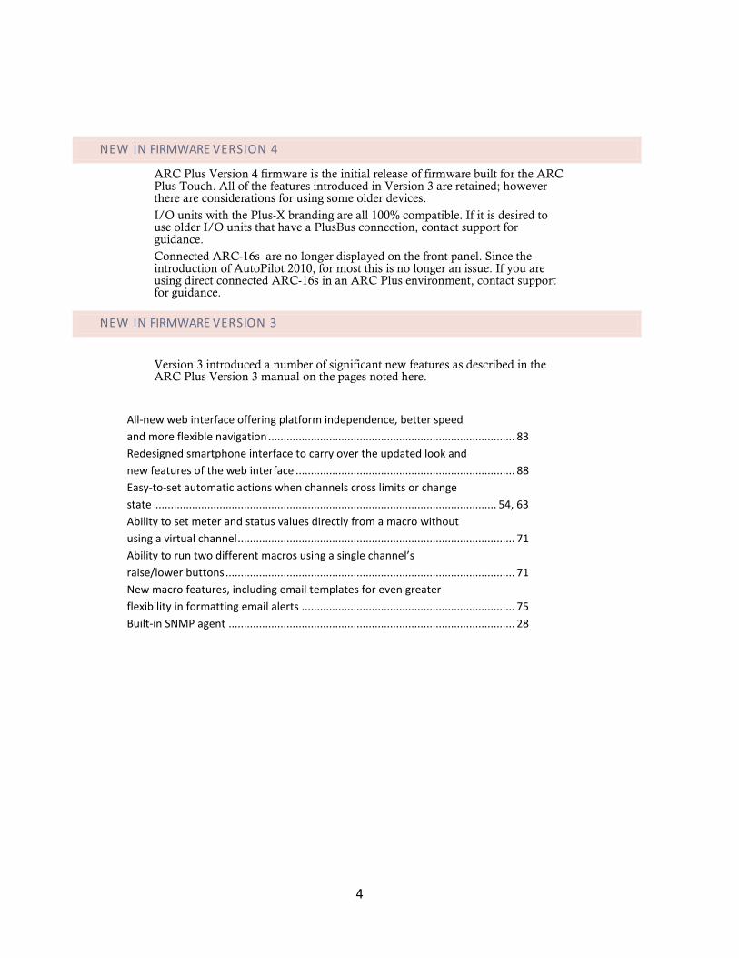
NEW IN FIRMWARE VERSION 4
ARC Plus Version 4 firmware is the initial release of firmware built for the ARC Plus Touch. All of the features introduced in Version 3 are retained; however there are considerations for using some older devices. I/O units with the Plus-X branding are all 100% compatible. If it is desired to use older I/O units that have a PlusBus connection, contact support for guidance. Connected ARC-16s are no longer displayed on the front panel. Since the introduction of AutoPilot 2010, for most this is no longer an issue. If you are using direct connected ARC-16s in an ARC Plus environment, contact support for guidance.
NEW IN FIRMWARE VERSION 3
Version 3 introduced a number of significant new features as described in the ARC Plus Version 3 manual on the pages noted here.
All-new web interface offering platform independence, better speed and more flexible navigation ................................................................................. 83 Redesigned smartphone interface to carry over the updated look and new features of the web interface ........................................................................ 88 Easy-to-set automatic actions when channels cross limits or change state ................................................................................................................ 54, 63 Ability to set meter and status values directly from a macro without using a virtual channel ........................................................................................... 71 Ability to run two different macros using a single channel’s raise/lower buttons ............................................................................................... 71 New macro features, including email templates for even greater flexibility in formatting email alerts ...................................................................... 75 Built-in SNMP agent .............................................................................................. 28
4
Contents
CONTENTS
About the ARC Plus System ..................................................................................................................................... 3
Components and documentation ............................................................................................................................. 3 New In Firmware Version 4 ....................................................................................................................................... 4 New In Firmware Version 3 ....................................................................................................................................... 4
Introduction.............................................................................................................................................................. 8
ARC Plus Touch ......................................................................................................................................................... 8
Front Panel ......................................................................................................................................................... 8
Rear Panel .......................................................................................................................................................... 9
Inputs and Outputs ................................................................................................................................................. 10
Plus-X Ethernet I/O .......................................................................................................................................... 10
PlusConnect™ Direct Transmitter Interfaces ................................................................................................... 10
Communications ..................................................................................................................................................... 11
AutoLoad Plus Software .................................................................................................................................. 11
Enhanced Speech Interface (ESI Plus) ............................................................................................................. 11
AutoPilot 2010 Software ................................................................................................................................. 12
Web-based monitoring and control ................................................................................................................ 13
Software and Firmware Updates ........................................................................................................................... 13 System Security ....................................................................................................................................................... 13
Operation ............................................................................................................................................................... 14
Touch Screen .......................................................................................................................................................... 14
Header .............................................................................................................................................................. 14
Footer ............................................................................................................................................................... 14
5
ARC Plus Touch
Scrollbars .......................................................................................................................................................... 15
Keypad ............................................................................................................................................................. 15
Command Buttons ........................................................................................................................................... 15
Help .................................................................................................................................................................. 15
Main Menu ............................................................................................................................................................. 16
Select Site ......................................................................................................................................................... 16
Channel Display ................................................................................................................................................ 16
Status Display ................................................................................................................................................... 16
Macros ............................................................................................................................................................. 17
Alarms .............................................................................................................................................................. 17
Events ............................................................................................................................................................... 17
Phone ............................................................................................................................................................... 17
Maintenance .................................................................................................................................................... 18
Configuration Menu ................................................................................................................................................ 18
Meter Mutes .................................................................................................................................................... 18
Status Mutes .................................................................................................................................................... 18
Calibration ........................................................................................................................................................ 19
System Menu .......................................................................................................................................................... 19
Clock ................................................................................................................................................................. 19
Network ........................................................................................................................................................... 20
Information ...................................................................................................................................................... 20
Installation.............................................................................................................................................................. 21
Needed Items .......................................................................................................................................................... 21 Recommended Sequence ....................................................................................................................................... 21
6
Contents
Rear Panel Connections .......................................................................................................................................... 22
Connecting to the Ethernet .......................................................................................................................... 22
Initial Front Panel Settings ...................................................................................................................................... 22
Network settings .............................................................................................................................................. 22
Time Settings .................................................................................................................................................... 22
Configuration Using AutoLoad Plus Software ........................................................................................................ 23
7
ARC Plus Touch
INTRODUCTION
The ARC Plus remote monitoring and control system takes advantage of the scalability of TCP/IP to provide site-to-site control, central monitoring and/or distributed access to more than 1,000 sites. Users can manage the system via the ARC Plus Touch front panel, web browser, smartphone, tablet and optional telephone and software interfaces, in any combination. Multi-site ARC Plus networks allow site-to-site control from the front panel of any ARC Plus or ARC Plus Touch, and automatic coordination of multiple facilities via onboard macros.
ARC PLUS TOUCH
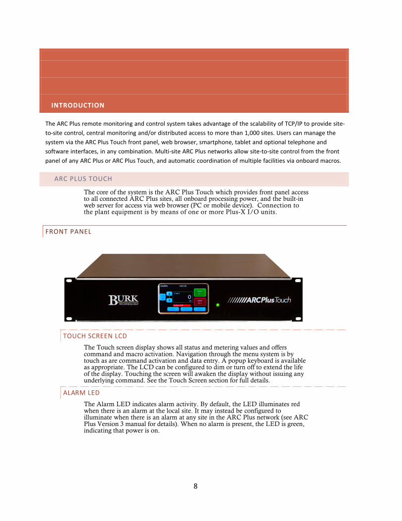
The core of the system is the ARC Plus Touch which provides front panel access to all connected ARC Plus sites, all onboard processing power, and the built-in web server for access via web browser (PC or mobile device). Connection to the plant equipment is by means of one or more Plus-X I/O units.
FRONT PANEL
TOUCH SCREEN LCD The Touch screen display shows all status and metering values and offers command and macro activation. Navigation through the menu system is by touch as are command activation and data entry. A popup keyboard is available as appropriate. The LCD can be configured to dim or turn off to extend the life of the display. Touching the screen will awaken the display without issuing any underlying command. See the Touch Screen section for full details.
ALARM LED The Alarm LED indicates alarm activity. By default, the LED illuminates red when there is an alarm at the local site. It may instead be configured to illuminate when there is an alarm at any site in the ARC Plus network (see ARC Plus Version 3 manual for details). When no alarm is present, the LED is green, indicating that power is on.
8
Introduction
REAR PANEL
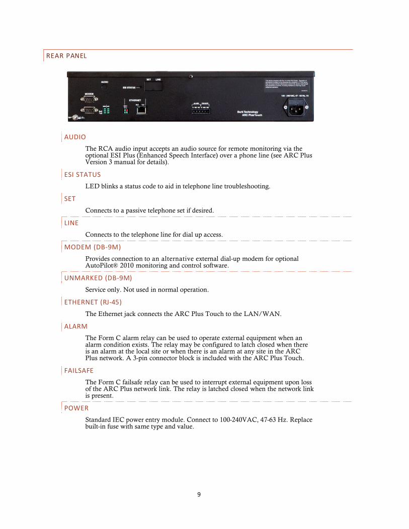
AUDIO The RCA audio input accepts an audio source for remote monitoring via the optional ESI Plus (Enhanced Speech Interface) over a phone line (see ARC Plus Version 3 manual for details).
ESI STATUS LED blinks a status code to aid in telephone line troubleshooting.
SET Connects to a passive telephone set if desired.
LINE Connects to the telephone line for dial up access.
MODEM (DB-9M) Provides connection to an alternative external dial-up modem for optional AutoPilot® 2010 monitoring and control software.
UNMARKED (DB-9M) Service only. Not used in normal operation.
ETHERNET (RJ-45) The Ethernet jack connects the ARC Plus Touch to the LAN/WAN.
ALARM The Form C alarm relay can be used to operate external equipment when an alarm condition exists. The relay may be configured to latch closed when there is an alarm at the local site or when there is an alarm at any site in the ARC Plus network. A 3-pin connector block is included with the ARC Plus Touch.
FAILSAFE The Form C failsafe relay can be used to interrupt external equipment upon loss of the ARC Plus network link. The relay is latched closed when the network link is present.
POWER Standard IEC power entry module. Connect to 100-240VAC, 47-63 Hz. Replace built-in fuse with same type and value.
9
ARC Plus Touch
INPUTS AND OUTPUTS
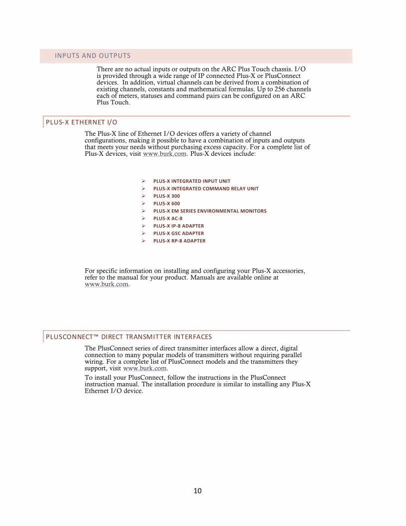
There are no actual inputs or outputs on the ARC Plus Touch chassis. I/O is provided through a wide range of IP connected Plus-X or PlusConnect devices. In addition, virtual channels can be derived from a combination of existing channels, constants and mathematical formulas. Up to 256 channels each of meters, statuses and command pairs can be configured on an ARC Plus Touch.
PLUS-X ETHERNET I/O The Plus-X line of Ethernet I/O devices offers a variety of channel configurations, making it possible to have a combination of inputs and outputs that meets your needs without purchasing excess capacity. For a complete list of Plus-X devices, visit www.burk.com. Plus-X devices include:
PLUS-X INTEGRATED INPUT UNIT PLUS-X INTEGRATED COMMAND RELAY UNIT PLUS-X 300 PLUS-X 600 PLUS-X EM SERIES ENVIRONMENTAL MONITORS PLUS-X AC-8 PLUS-X IP-8 ADAPTER PLUS-X GSC ADAPTER PLUS-X RP-8 ADAPTER
For specific information on installing and configuring your Plus-X accessories, refer to the manual for your product. Manuals are available online at www.burk.com.
PLUSCONNECT™ DIRECT TRANSMITTER INTERFACES The PlusConnect series of direct transmitter interfaces allow a direct, digital connection to many popular models of transmitters without requiring parallel wiring. For a complete list of PlusConnect models and the transmitters they support, visit www.burk.com. To install your PlusConnect, follow the instructions in the PlusConnect instruction manual. The installation procedure is similar to installing any Plus-X Ethernet I/O device.
10
Introduction
COMMUNICATIONS
AUTOLOAD PLUS SOFTWARE
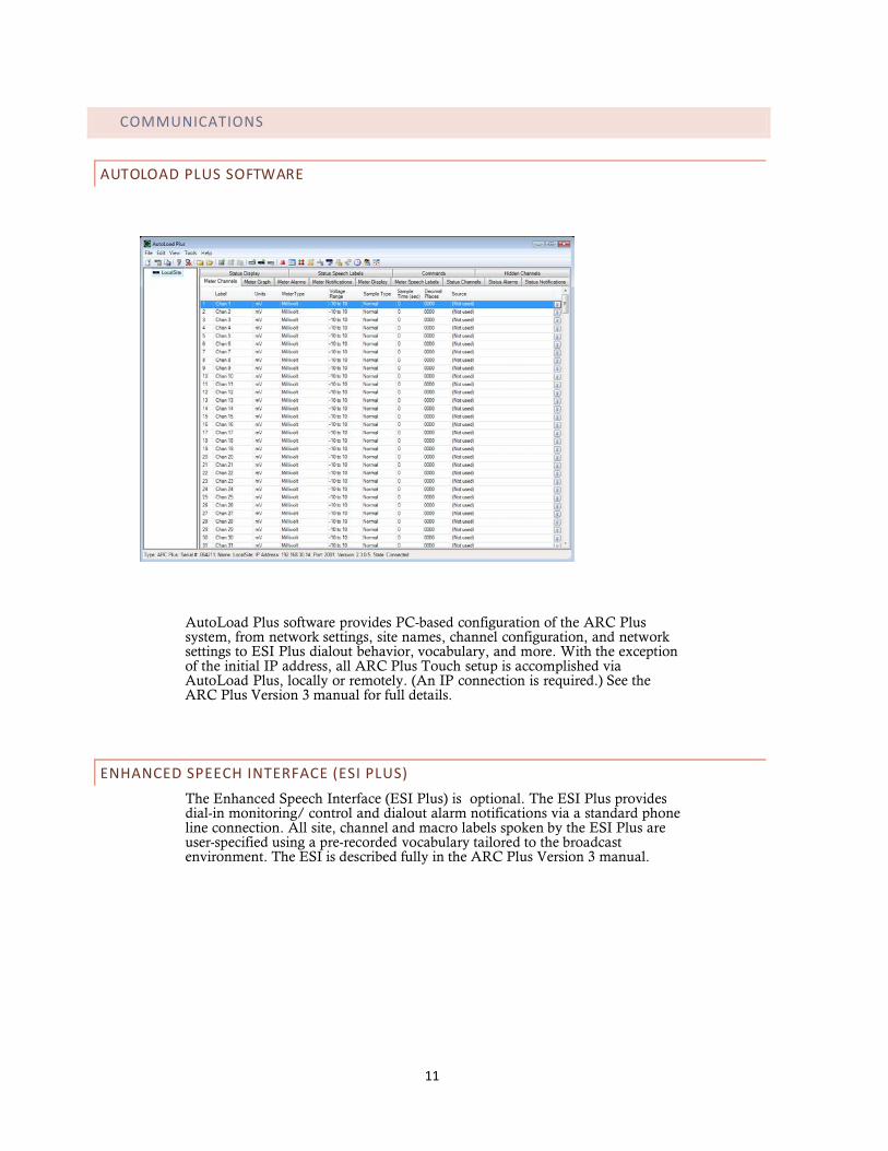
AutoLoad Plus software provides PC-based configuration of the ARC Plus system, from network settings, site names, channel configuration, and network settings to ESI Plus dialout behavior, vocabulary, and more. With the exception of the initial IP address, all ARC Plus Touch setup is accomplished via AutoLoad Plus, locally or remotely. (An IP connection is required.) See the ARC Plus Version 3 manual for full details.
ENHANCED SPEECH INTERFACE (ESI PLUS) The Enhanced Speech Interface (ESI Plus) is optional. The ESI Plus provides dial-in monitoring/ control and dialout alarm notifications via a standard phone line connection. All site, channel and macro labels spoken by the ESI Plus are user-specified using a pre-recorded vocabulary tailored to the broadcast environment. The ESI is described fully in the ARC Plus Version 3 manual.
11

ARC Plus Touch
AUTOPILOT 2010 SOFTWARE
AutoPilot 2010 provides PC-based monitoring and control for the ARC Plus network. IP connectivity allows simultaneous control of multiple sites, while optional dial-up modem connectivity provides a means to access single sites from outside the LAN. AutoPilot 2010 provides a customizable GUI, logging and automatic report generation, network and SNMP monitoring, and integration of remote security cameras.
12
Introduction
WEB-BASED MONITORING AND CONTROL
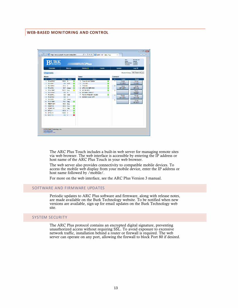
The ARC Plus Touch includes a built-in web server for managing remote sites via web browser. The web interface is accessible by entering the IP address or host name of the ARC Plus Touch in your web browser. The web server also provides connectivity to compatible mobile devices. To access the mobile web display from your mobile device, enter the IP address or host name followed by /mobile/. For more on the web interface, see the ARC Plus Version 3 manual.
SOFTWARE AND FIRMWARE UPDATES
Periodic updates to ARC Plus software and firmware, along with release notes, are made available on the Burk Technology website. To be notified when new versions are available, sign up for email updates on the Burk Technology web site.
SYSTEM SECURITY
The ARC Plus protocol contains an encrypted digital signature, preventing unauthorized access without requiring SSL. To avoid exposure to excessive network traffic, installation behind a router or firewall is required. The web server can operate on any port, allowing the firewall to block Port 80 if desired.
13
ARC Plus Touch
OPERATION
The touch screen on the ARC Plus Touch allows operators to monitor and control any site in the ARC Plus network. Additionally, calibration, alarm muting, maintenance mode, network configuration and dial-in and dial-out options are available. All other configuration is conveniently done with the AutoLoad software program.
Commands and configuration changes are effective for the selected site. The currently selected site is always displayed in the header.
Calibration and Maintenance mode can only be changed on the local site.
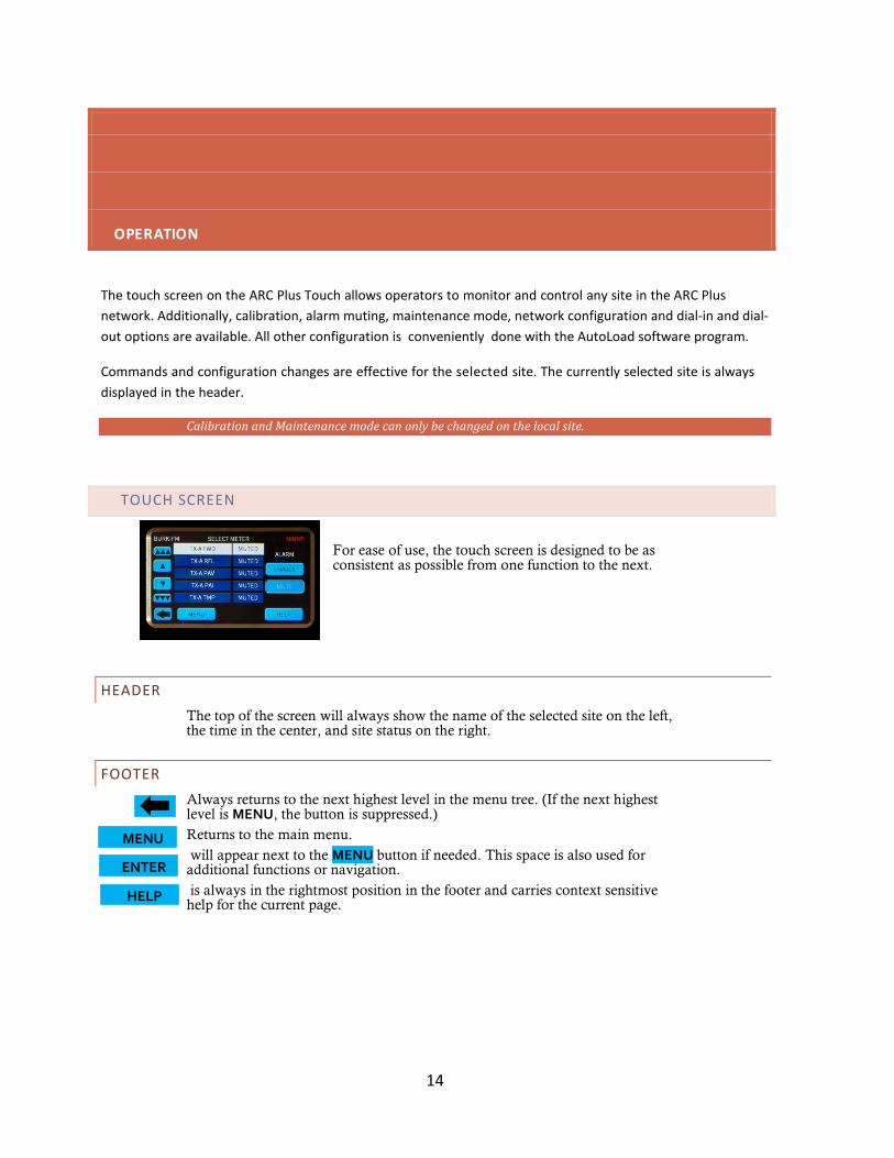
TOUCH SCREEN
For ease of use, the touch screen is designed to be as consistent as possible from one function to the next.
HEADER The top of the screen will always show the name of the selected site on the left, the time in the center, and site status on the right.
FOOTER Always returns to the next highest level in the menu tree. (If the next highest level is MENU, the button is suppressed.) Returns to the main menu. will appear next to the MENU button if needed. This space is also used for additional functions or navigation. is always in the rightmost position in the footer and carries context sensitive help for the current page.
MENU
ENTER
HELP
14

Operation
It is possible to override a command button to execute a macro instead of a raise or lower command. See ARC Plus Version 3 manual for more on overriding command channels.
SCROLLBARS If scrollbars are necessary, they will appear on the left edge of the screen. The inside buttons advance by one line, while the outside buttons move by multiple lines.
KEYPAD A keypad may be used whenever the KEYPAD button appears on the left side of the display.
COMMAND BUTTONS The right side of the display is generally reserved for actions such as channel raise and lower commands, macro start and stop commands and various enable/disable functions.
Pushing a command button
executes the raise or lower command. For momentary commands, the duration is set in AutoLoad. Holding the command button does not extend the duration, but pressing again during the command immediately restarts the duration.
HELP Context sensitive help is always available on the touch screen. Simply press HELP in the lower right hand corner.
15
ARC Plus Touch
MAIN MENU
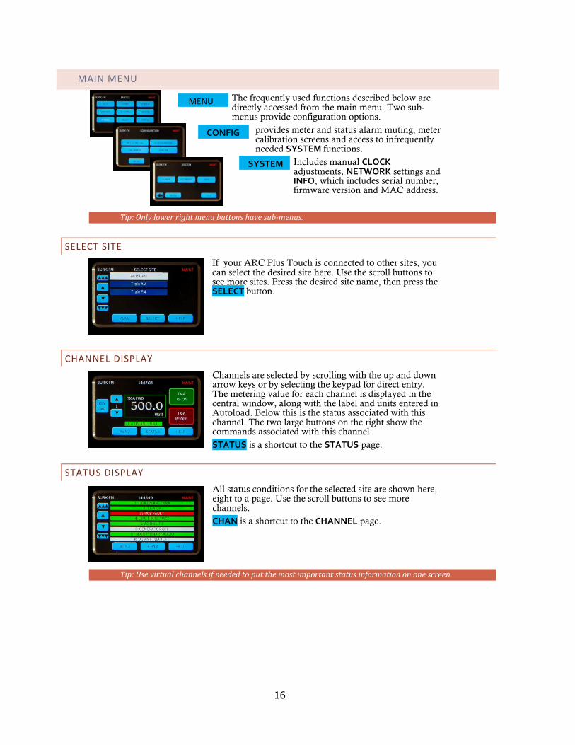
The frequently used functions described below are directly accessed from the main menu. Two sub-menus provide configuration options.
provides meter and status alarm muting, meter calibration screens and access to infrequently needed SYSTEM functions.
Includes manual CLOCK adjustments, NETWORK settings and INFO, which includes serial number, firmware version and MAC address.
Tip: Only lower right menu buttons have sub-menus.
SELECT SITE If your ARC Plus Touch is connected to other sites, you can select the desired site here. Use the scroll buttons to see more sites. Press the desired site name, then press the SELECT button.
CHANNEL DISPLAY Channels are selected by scrolling with the up and down arrow keys or by selecting the keypad for direct entry. The metering value for each channel is displayed in the central window, along with the label and units entered in Autoload. Below this is the status associated with this channel. The two large buttons on the right show the commands associated with this channel. STATUS is a shortcut to the STATUS page.
STATUS DISPLAY All status conditions for the selected site are shown here, eight to a page. Use the scroll buttons to see more channels. CHAN is a shortcut to the CHANNEL page.
Tip: Use virtual channels if needed to put the most important status information on one screen.
CONFIG
SYSTEM
MENU
16
Operation
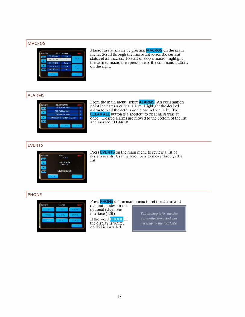
This setting is for the site currently connected, not necessarily the local site.
MACROS Macros are available by pressing MACROS on the main menu. Scroll through the macro list to see the current status of all macros. To start or stop a macro, highlight the desired macro then press one of the command buttons on the right.
ALARMS From the main menu, select ALARMS. An exclamation point indicates a critical alarm. Highlight the desired alarm to read the details and clear individually. The CLEAR ALL button is a shortcut to clear all alarms at once. Cleared alarms are moved to the bottom of the list and marked CLEARED.
EVENTS Press EVENTS on the main menu to review a list of system events. Use the scroll bars to move through the list.
PHONE Press PHONE on the main menu to set the dial-in and dial-out modes for the optional telephone interface (ESI). If the word PHONE in the display is white, no ESI is installed.
17
ARC Plus Touch
Never depend on the remote control for
personal safety. Always remove power
before performing maintenance.
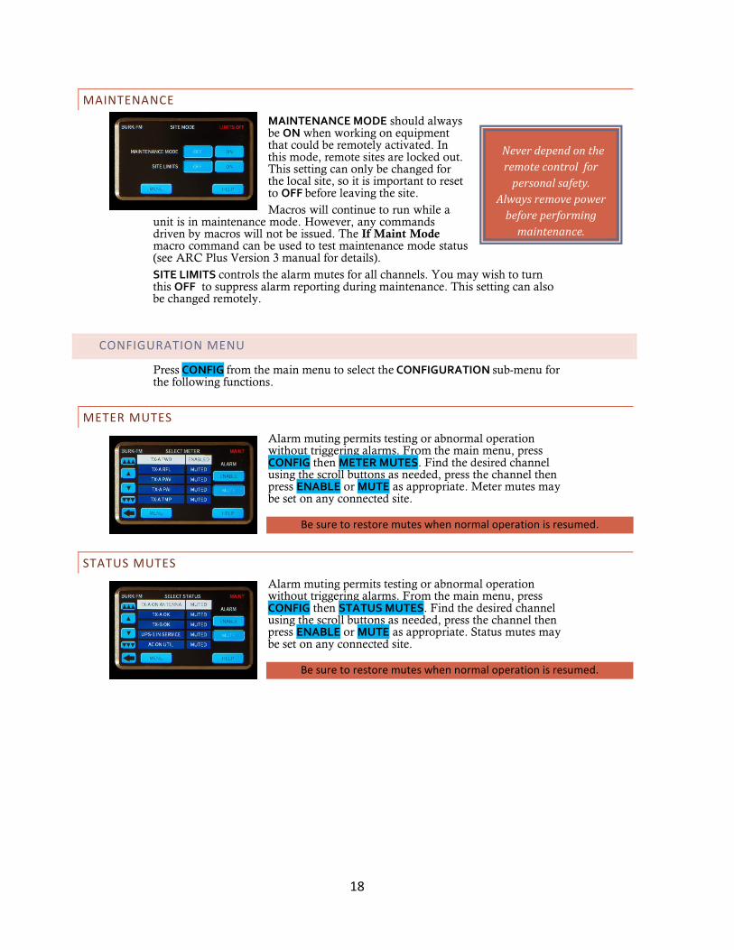
MAINTENANCE MAINTENANCE MODE should always be ON when working on equipment that could be remotely activated. In this mode, remote sites are locked out. This setting can only be changed for the local site, so it is important to reset to OFF before leaving the site. Macros will continue to run while a
unit is in maintenance mode. However, any commands driven by macros will not be issued. The If Maint Mode macro command can be used to test maintenance mode status (see ARC Plus Version 3 manual for details). SITE LIMITS controls the alarm mutes for all channels. You may wish to turn this OFF to suppress alarm reporting during maintenance. This setting can also be changed remotely.
CONFIGURATION MENU
Press CONFIG from the main menu to select the CONFIGURATION sub-menu for the following functions.
METER MUTES Alarm muting permits testing or abnormal operation without triggering alarms. From the main menu, press CONFIG then METER MUTES. Find the desired channel using the scroll buttons as needed, press the channel then press ENABLE or MUTE as appropriate. Meter mutes may be set on any connected site.
Be sure to restore mutes when normal operation is resumed.
STATUS MUTES Alarm muting permits testing or abnormal operation without triggering alarms. From the main menu, press CONFIG then STATUS MUTES. Find the desired channel using the scroll buttons as needed, press the channel then press ENABLE or MUTE as appropriate. Status mutes may be set on any connected site.
Be sure to restore mutes when normal operation is resumed.
18
Operation
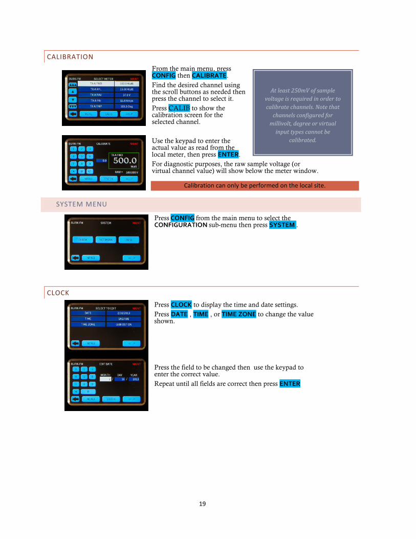
At least 250mV of sample voltage is required in order to calibrate channels. Note that
channels configured for millivolt, degree or virtual
input types cannot be calibrated.
CALIBRATION From the main menu, press CONFIG then CALIBRATE. Find the desired channel using the scroll buttons as needed then press the channel to select it. Press CALIB to show the calibration screen for the selected channel. Use the keypad to enter the actual value as read from the local meter, then press ENTER. For diagnostic purposes, the raw sample voltage (or virtual channel value) will show below the meter window.
Calibration can only be performed on the local site.
SYSTEM MENU
Press CONFIG from the main menu to select the CONFIGURATION sub-menu then press SYSTEM .
CLOCK Press CLOCK to display the time and date settings. Press DATE , TIME , or TIME ZONE to change the value shown.
Press the field to be changed then use the keypad to enter the correct value. Repeat until all fields are correct then press ENTER
19
ARC Plus Touch
NETWORK
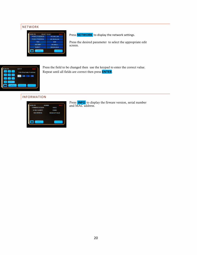
Press NETWORK to display the network settings.
Press the desired parameter to select the appropriate edit screen.
Press the field to be changed then use the keypad to enter the correct value. Repeat until all fields are correct then press ENTER.
INFORMATION Press INFO to display the firware version, serial number and MAC address.
20
Installation
INSTALLATION
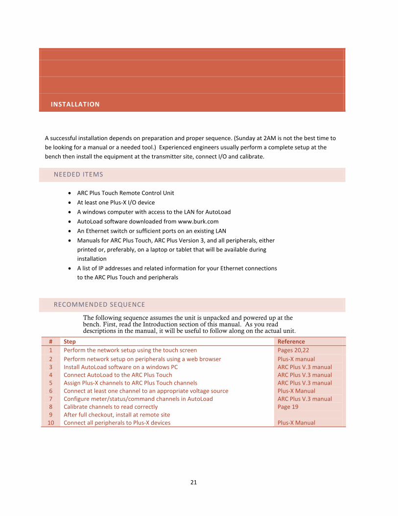
A successful installation depends on preparation and proper sequence. (Sunday at 2AM is not the best time to be looking for a manual or a needed tool.) Experienced engineers usually perform a complete setup at the bench then install the equipment at the transmitter site, connect I/O and calibrate.
NEEDED ITEMS
• ARC Plus Touch Remote Control Unit • At least one Plus-X I/O device • A windows computer with access to the LAN for AutoLoad • AutoLoad software downloaded from www.burk.com • An Ethernet switch or sufficient ports on an existing LAN • Manuals for ARC Plus Touch, ARC Plus Version 3, and all peripherals, either
printed or, preferably, on a laptop or tablet that will be available during installation
• A list of IP addresses and related information for your Ethernet connections to the ARC Plus Touch and peripherals
RECOMMENDED SEQUENCE
The following sequence assumes the unit is unpacked and powered up at the bench. First, read the Introduction section of this manual. As you read descriptions in the manual, it will be useful to follow along on the actual unit.
# Step Reference 1 Perform the network setup using the touch screen Pages 20,22 2 3 4 5 6 7 8 9
10
Perform network setup on peripherals using a web browser Install AutoLoad software on a windows PC Connect AutoLoad to the ARC Plus Touch Assign Plus-X channels to ARC Plus Touch channels Connect at least one channel to an appropriate voltage source Configure meter/status/command channels in AutoLoad Calibrate channels to read correctly After full checkout, install at remote site Connect all peripherals to Plus-X devices
Plus-X manual ARC Plus V.3 manual ARC Plus V.3 manual ARC Plus V.3 manual Plus-X Manual ARC Plus V.3 manual Page 19 Plus-X Manual
21

ARC Plus Touch
REAR PANEL CONNECTIONS
For most installations only the Ethernet connection and power connections are necessary. After completing the initial checkout, you may wish to make additional connections for an external alarm, failsafe, a modem connection or the optional telephone interface.
Install the ARC Plus Touch in a location with access to your LAN/WAN. If you intend to operate the ARC Plus Touch in a stand-alone configuration (dial-up modem and telephone access, but no TCP/IP connection), a network connection must still be available for on-the-bench configuration. A crossover cable may also be used to connect a computer directly to the ARC Plus Touch for configuration.
CONNECTING TO THE ETHERNET Connect the ARC Plus Touch port marked ETHERNET to your LAN/WAN using CAT5e cable.
INITIAL FRONT PANEL SETTINGS
Most of the configuration of the ARC Plus Touch will be done in the AutoLoad software program which may be downloaded from www.burk.com/downloads. You will first need to use the front panel configuration pages to give the ARC Plus Touch an IP address and set the time.
NETWORK SETTINGS See page 20 for help editing the network information. Enter the PRIVATE IP ADDRESS, PUBLIC IP ADDRESS and PORT values that will identify the ARC Plus Touch as a unique device on the network. The private IP is the address you will use to access the ARC Plus Touch on your company LAN/WAN. The public IP address is used when connecting to the ARC Plus Touch from outside the LAN/WAN, provided your network allows connections from outside. If the ARC Plus Touch will not be accessible from outside the network, enter the private IP address. Additional network settings are available in AutoLoad Plus, but the ARC Plus Touch must first be made accessible by setting the initial IP address from the front panel.
TIME SETTINGS See page 19 for help editing the date, time, time zone and DST settings from the front panel. These settings may also be made from AutoLoad Plus.
22
Installation
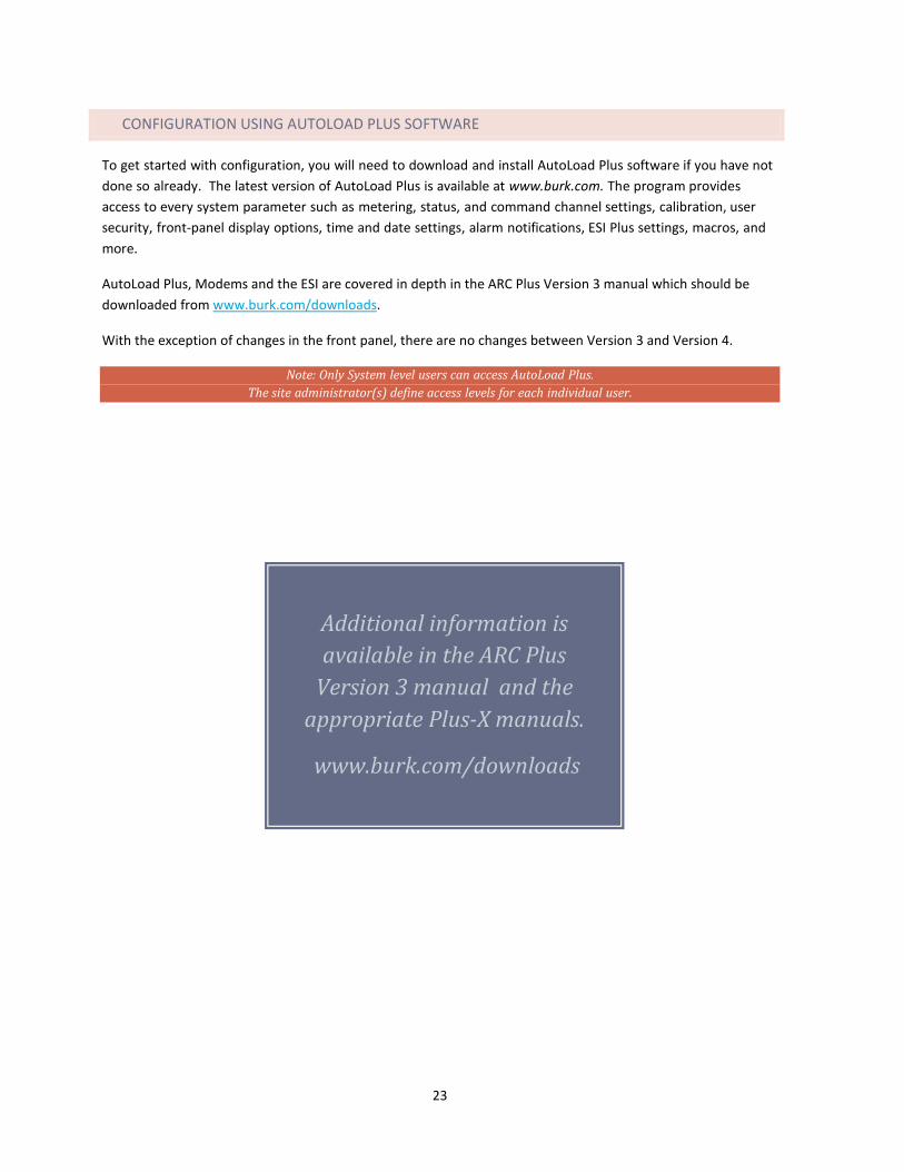
Additional information is available in the ARC Plus
Version 3 manual and the appropriate Plus-X manuals.
www.burk.com/downloads
CONFIGURATION USING AUTOLOAD PLUS SOFTWARE
To get started with configuration, you will need to download and install AutoLoad Plus software if you have not done so already. The latest version of AutoLoad Plus is available at www.burk.com. The program provides access to every system parameter such as metering, status, and command channel settings, calibration, user security, front-panel display options, time and date settings, alarm notifications, ESI Plus settings, macros, and more.
AutoLoad Plus, Modems and the ESI are covered in depth in the ARC Plus Version 3 manual which should be downloaded from www.burk.com/downloads.
With the exception of changes in the front panel, there are no changes between Version 3 and Version 4.
Note: Only System level users can access AutoLoad Plus. The site administrator(s) define access levels for each individual user.
23


![On [a,b], ARC = On [1, 16], find ARC for. On [a,b], ARC = On [1, 16], find ARC for ARC = =](https://img.pdfslide.us/doc/110x75/5697c0281a28abf838cd6d3a/on-ab-arc-on-1-16-find-arc-for-on-ab-arc-on-1-16-find.jpg)