Embed Size (px)
Citation preview

email: [email protected] website: http://www.Adaptsoft.com 1733 Woodside Road, Suite 220, Redwood City, California, 94061, USA, Tel: (650) 306-2400 Fax (650) 364-4678
STRUCTURAL ENGINEERING CONSULTANTS
ARBORVIEW PROJECT
Structural Design Criteria For Post-Tensioned Ground-Supported Slabs
Prepared by
The Structural Engineering Consultants (SECI)
27200 Tourney Rd, Suite 390 Valencia, CA 91355
For
FIELDSTONE COMMUNITIES, INC
Santa Clarita, CA 91350
calc_legend_plaza
TN213_SOG_design_criteria_12 020606

LIST OF CONTENTS
1. DESIGN SCOPE 2. DESIGN CONSIDERATIONS 3. CALCULATION RESULTS
• Plan 1A • Plan 2A • Plan 2C • Plan 3A • Plan 3B
3
DESIGN SCOPE
This outlines the criteria to be used for the structural engineering design of the post-tensioned ground-supported slabs of the subject matter project.
The structural design for the remainder members of the concrete frame is reported in a separate structural calculation package. Work reported separately includes both the gravity and lateral aspects of the design. The calculations reported herein are based on the set of drawings listed in the appendix of this report. The parameters used for the design of the slabs are based on preliminary values provided in the following: Letter from: Pacific Soils Engineering, Inc., located at 10553 Progress Way, Cypress, CA 90630, Tel (714) 220 0770, Fax: (714) 220 9599, signed by Paul Ernst, RGE and dated, January 30, 2006. Addressed to: Fieldstone Communities, Inc., located at 21080 Center Pointe Parkway, Suite 102, Santa Clarita, CA 91350.

4
1. DESIGN CONSIDERATIONS 1.1 Structural System The structural system of the foundation is a mat slab of uniform thickness with down turned perimeter beams resting on soil. The slab is post-tensioned in both directions with straight tendons placed at mid-depth of the slab. A moisture and vapor retarding system is recommended by the soil engineer to be placed below the slab.1 This design criteria is used for several configurations of the slab foundations of the subject matter tract. Unless specified otherwise, the slab thickness is 9 inch. The perimeter beams are 24 inch deep and 12 inch wide.
1.2 Applicable Codes The design is based on UBC 1997. Where this code is mute, PTI’s recommendations given in “Design of Post-Tensioned Slabs-on-Ground” is used. Both of the above documents are simplifications derived from a more rigorous finite element plate analysis. As such, they do not fully cover the range of loading and configurations of the subject project. Where design recommendations are lacking, ADAPT’s SOG Manual on “Post-Tensioned Foundation Slabs on Expansive or Compressible Soil” is used. Using the code design criteria, the analysis is based on a finite element program that accounts for the following:
• Authentic representation of geometry of the slab, beams, depressions, steps, thickenings, and material properties
• Modeling of tendons, where they occur (correct profile, eccentricity, stress losses)
• Ability to apply specified edge lift as required by code and allow for separation of slab from soil
• Ability to apply centre lift as required by code • Reduction of the local stresses to the representative values for
code • Use of a shell element to account for both the bending and in-plane
response of the slab
1.3 Structural Documents The calculations and structural drawings conclude with:
(i) The detailed layout of tendons in the foundation slab, showing the location, profile and height of each;
1 10-mil plastic membrane, such as Visqueen.

5
(ii) The non-prestressed reinforcement over and above the post-tensioning tendons, at all locations on the slab;
(iii) Construction notes and details.

6
1.4 Material Properties
1.4.1 Concrete: Weight = 150 pcf Cylinder Strength at 28 days for slabs = 4000 psi Modulus of Elasticity (instantaneous) = 3605 ksi
Modulus of Elasticity (creep) = 1800 ksi Creep Coefficient = 2
1.4.2 Post-Tensioning: MATERIAL Low Relaxation
Strand Diameter = 0.50 in nominal Strand Area = 0.153 in2 Modulus of Elasticity = 28000 ksi Guaranteed Ultimate Strength (fpu) = 270 ksi Average Effective Stress (fse) = 175 ksi
SYSTEM System unbonded Angular Coefficient of Friction (µ) = 0.07 Wobble Coefficient of Friction (K) = 0.001 rad/ft Anchor Set (Wedge Draw-in) = 0.25 inch
1.4.3 Non-prestressed Reinforcement:
Yield Strength = 60 ksi Modulus of Elasticity = 30000 ksi
1.4.4 Friction Between Foundation Slab and Soil: Friction Coefficient = 0.40
1.4.4 Design Loading A base load common to all foundation slabs is used. In addition to the base load, each slab is subjected to loads that reflect the construction of the respective superstructure. BASE LOAD DEAD LOAD
Self weight = based on volume Partitions = 20.0 psf Total = 20.0 psf + self weight

7
LIVE LOAD
Uniformly Distributed = 40.0 psf
BUILDING SPECIFIC LOADS These consist of dead, live, and seismic loads. They are shown on the design plans prepared for each foundation.
2. LOAD CASES; LOAD COMBINATIONS AND STRESSES Three series of checks are performed:
• Service condition • Initial (transfer of prestressing) condition • Strength condition
The foundation is sized based on the in-service condition. It is checked against other load cases, and reinforced if necessary. The following describes the conditions and criteria used for each.
2.2 Serviceability Load combinations (i) Average Precompression: The post-tensioning design targets an
average precompression over the entire cross-sectional area of the foundation not less than 75 psi after all losses. In most instances a precompression around 100 psi is used.
(ii) Load Cases and Allowable Stresses
The load cases for in-service condition are “edge lift” and “center lift.” The design parameters for these two cases are specified by the soil engineer and given below:
• Center lift o ym = 1.5 in. o em = 5.0 ft
• Edge lift
o ym = 0.40 in. o em = 3.5 ft
For each of the preceding load cases, representative concrete stresses are calculated and compared with the allowable values for code compliance. The allowable values are:

8
Allowable Tensile Stress:
ft = 6 * f’c0.5
= 6 * 4000 0.5 = 379 psi
Allowable Compressive Stress:
fc = 0.45 * f’c = 0.45 * 4000 = 1800 psi
Allowable Shear Stress
vc = 1.7 * f’c0.5 + 0.2fp = 1.7 * 4000 0.5 + 0.2 * 100 = 127 psi where fp is the average precompression
Soil Bearing Pressure
• Bearing pressure under the slab: 1000 psf • Bearing pressure under beam stem (18 “ or more below
grade) = 1500 psf
Allowable Deflection Maximum differential displacement (relative deflection) of the
top of the slab 1/300 over any length of slab
(iii) Load Combinations For Serviceability Check
“Total” in-service load combination (stress check): U = 1.00DL + 1.00LL + 1.00Prestressing
2.3 Initial Condition (Transfer of Prestressing Force)
Load combination for stress check at transfer of prestressing: U = 1.15 * Prestressing
Allowable Tensile Stress:
ft = 3 * f’c0.5
= 3 * 4000 0.5 = 189 psi
Allowable Compressive Stress:
9
fc = 0.60 * f’c
= 0.60 * 4000 = 2400 psi
2.4 Strength Load Combinations The strength load combination is used to check the adequacy of the foundation slab under seismic forces .The strength requirement for each location is established using the following factored load combinations:
U = 1.20DL + 1.00LL + 1.00Secondary + 1.00E
U = 0.90DL + 1.00Secondary + 1.00E
Where “secondary” consists of the hyperstatic moments, shears and reactions due to post-tensioning.
PLAN 1A

02/09/0618:57:43
Plan_1_CL_3.adm
Post-Tensioned Slab-On-GroundArborview
RMM
ADAPT
Plan Geometry
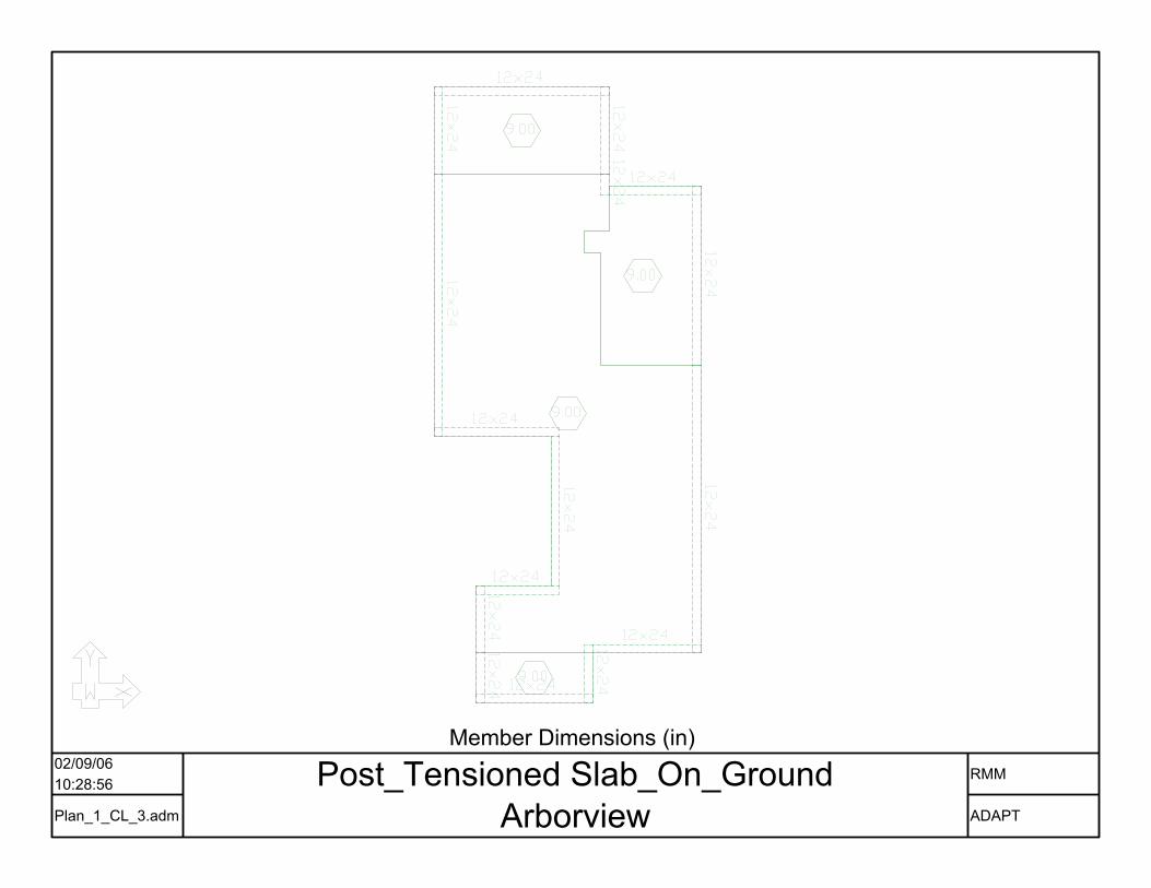
02/09/0610:28:56
Plan_1_CL_3.adm
Post_Tensioned Slab_On_GroundArborview
RMM
ADAPT
Member Dimensions (in)

02/09/0610:33:28
Plan_1_CL_3.adm
Post_Tensioned Slab_On_GroundArborview
RMM
ADAPT
Member Identifications

02/09/0610:39:15 Post_Tensioned Slab_On_Ground
ArborviewRMM
ADAPT
Plan Geometry

02/09/0610:55:40
Plan_1_CL_3.adm
Post_Tensioned Slab_On_GroundArborview
RMM
ADAPT
Dead Load Plan(ksf, k/ft, kip)

02/09/0610:57:40
Plan_1_CL_3.adm
Post_Tensioned Slab_On_GroundArborview
RMM
ADAPT
Live Load Plan (ksf,k/ft,k)
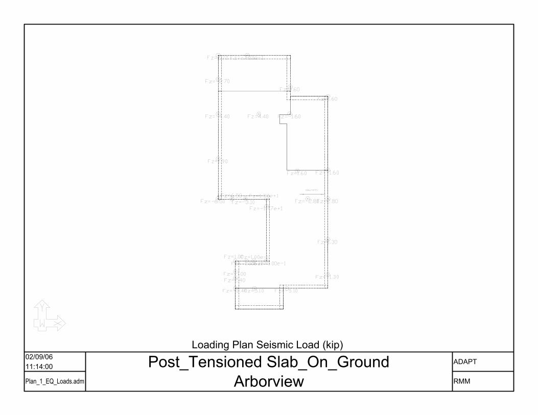
02/09/0611:14:00
Plan_1_EQ_Loads.adm
Post_Tensioned Slab_On_GroundArborview
ADAPT
RMM
Loading Plan Seismic Load (kip)
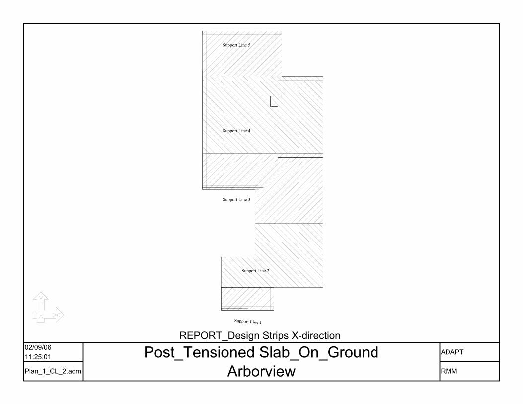
Support Line 1
Support Line 2
Support Line 3
Support Line 4
Support Line 5
02/09/0611:25:01
Plan_1_CL_2.adm
Post_Tensioned Slab_On_GroundArborview
ADAPT
RMM
REPORT_Design Strips X-direction
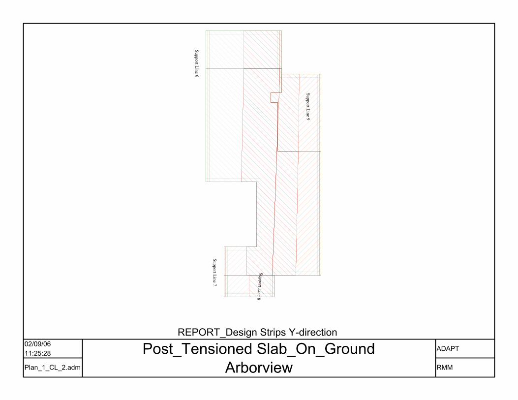
Support Line 6
Support Line 7
Support Line 8
Support Line 9
02/09/0611:25:28
Plan_1_CL_2.adm
Post_Tensioned Slab_On_GroundArborview
ADAPT
RMM
REPORT_Design Strips Y-direction

Support Line 1
Support Line 2
Support Line 3
Support Line 4
Support Line 5
02/09/0611:25:49
Plan_1_CL_2.adm
Post_Tensioned Slab_On_GroundArborview
ADAPT
RMM
REPORT_Support Lines X-direction

Support Line 6
Support Line 7
Support Line 8
Support Line 9
02/09/0611:26:15
Plan_1_CL_2.adm
Post_Tensioned Slab_On_GroundArborview
ADAPT
RMM
REPORT_Support Lines Y-direction

02/09/0611:31:15
Plan_1_CL_3.adm
Post_Tensioned Slab_On_GroundArborview
RMM
ADAPT
Tendon Plan

02/09/0611:34:30 Post_Tensioned Slab_On_Ground
ArborviewRMM
ADAPT
Tendon 3D View

02/09/0611:21:25
Plan_1_CL_2.adm
Post_Tensioned Slab_On_GroundArborview
ADAPT
RMM
Mesh

• CENTER LIFT DESIGN

02/09/0611:37:55
Plan_1_CL_2.adv
Post_Tensioned Slab_On_GroundZ-Translation - Service
Unit :
Deformation
Deflection Profile
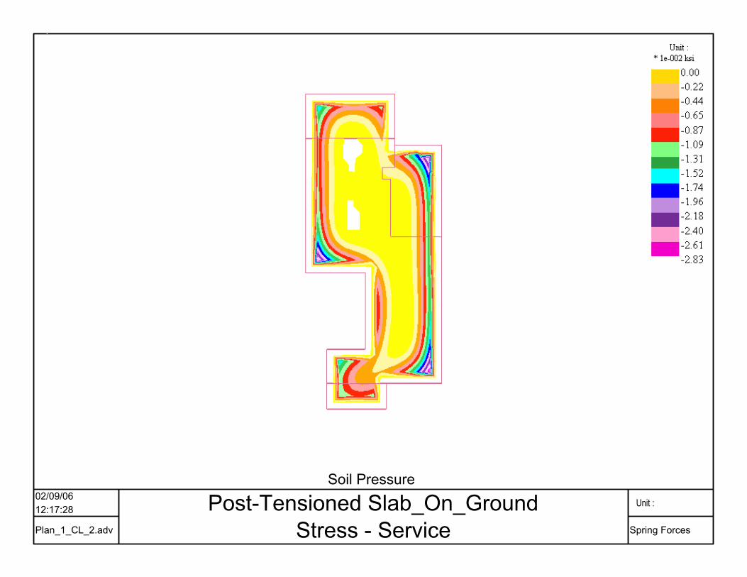
02/09/0612:17:28
Plan_1_CL_2.adv
Post-Tensioned Slab_On_GroundStress - Service
Unit :
Spring Forces
Soil Pressure
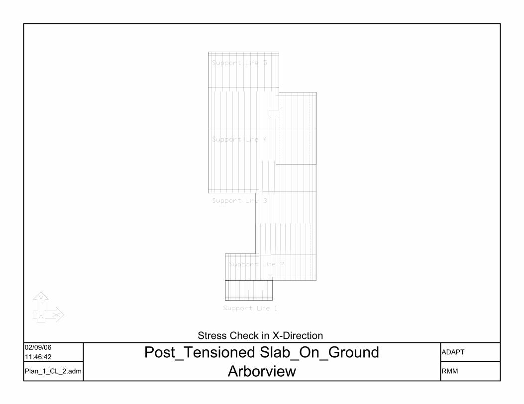
02/09/0611:46:42
Plan_1_CL_2.adm
Post_Tensioned Slab_On_GroundArborview
ADAPT
RMM
Stress Check in X-Direction

02/09/0611:47:30
Plan_1_CL_2.adm
Post_Tensioned Slab_On_GroundArborview
ADAPT
RMM
Stress Check in Y-Direction

• EDGE LIFT DESIGN

02/09/0612:13:20
Plan_1_EL_2.adv Z-Translation - Service Unit :
Deformation

02/09/0612:16:00
Plan_1_EL_2.adv
Post-Tensioned Slab_On_GroundStress - Service
Unit :
Spring Forces
Soil Pressure
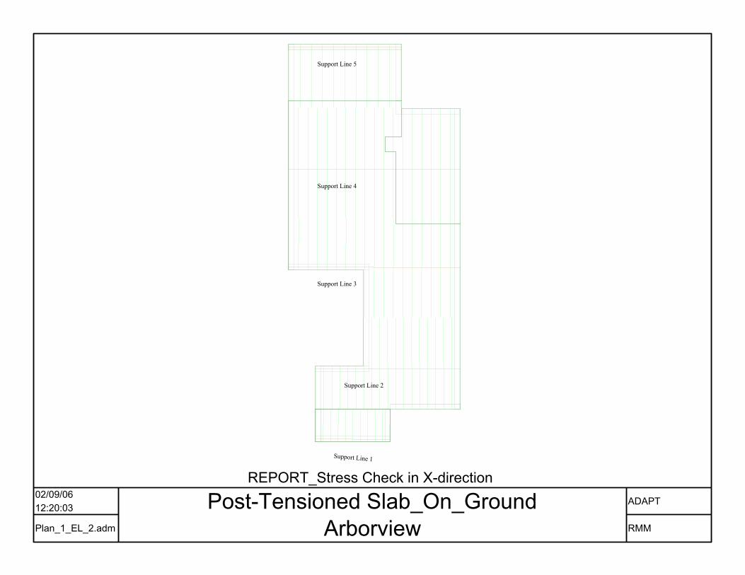
Support Line 1
Support Line 2
Support Line 3
Support Line 4
Support Line 5
02/09/0612:20:03
Plan_1_EL_2.adm
Post-Tensioned Slab_On_GroundArborview
ADAPT
RMM
REPORT_Stress Check in X-direction
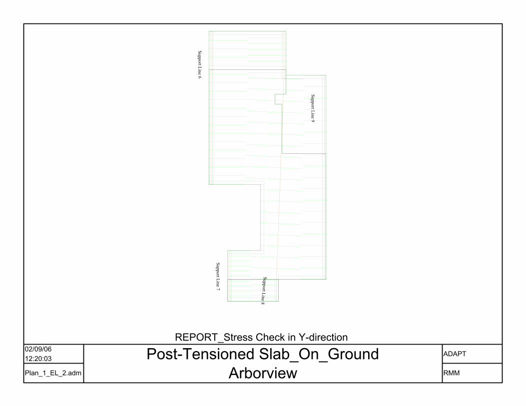
Support Line 6
Support Line 7
Support Line 8
Support Line 9
02/09/0612:20:03
Plan_1_EL_2.adm
Post-Tensioned Slab_On_GroundArborview
ADAPT
RMM
REPORT_Stress Check in Y-direction