Embed Size (px)
Citation preview

ARB Approved
Installation, Operation and Maintenance Manual
For the Phil-Tite Phase I Vapor Recovery System As Certified by Executive Order VR-101-M

Phil-Tite Installation, Operation and Maintenance Manual, Page ii Executive Order VR-101-M
NOTICE:
The ARB Approved Installation, Operation and Maintenance Manual for the Phil-Tite Phase I EVR System describes the tools and methods required to install the Phil-Tite Phase I EVR System. Unless specified otherwise, only technicians that are trained and certified by Phil-Tite (i.e. Phil-Tite Certified Technicians) are able to perform installation, maintenance or repairs of components manufactured by Phil-Tite or the warranty will be void. A list of Phil-Tite Certified Technicians can be viewed at http://www.franklinfueling.com/service/. To schedule a training class, Phil-Tite can be contacted at the following:
Stan Brodecki, Allan Busch, or Steve Langlie Enhanced Vapor Recovery Systems Franklin Fueling Systems Phone: 800-225-9787 Email: [email protected]
[email protected] [email protected]
It is the responsibility of each Phil-Tite Certified Technician to be familiar with the current requirements of state, federal and local codes for installation and repair of gasoline dispensing equipment. It is also the responsibility of the Phil-Tite Certified Technician to be aware of all necessary safety precautions and site safety requirements to assure a safe and trouble free installation.
Phil-Tite Installation, Operation and Maintenance Manual, Page iii Executive Order VR-101-M
Summary of Maintenance Activities Required of the Phil-Tite Phase I Vapor Recovery System1
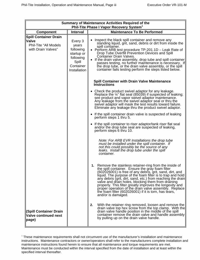
Component Interval Maintenance To Be Performed Spill Container Drain Valve
Phil-Tite “All Models with Drain Valves”
(Spill Container Drain Valve continued next page)
Every 3 years
following startup or following
Spill Container Installation
Inspect the black spill container and remove any
standing liquid, grit, sand, debris or dirt from inside the spill container.
Perform ARB test procedure TP-201.1D – Leak Rate of Drop Tube Overfill Prevention Devices and Spill Container Drain Valves.
If the drain valve assembly, drop tube and spill container passes testing, no further maintenance is necessary. If the drop tube, or the drain valve assembly, or the spill container fails testing perform the steps listed below.
Spill Container with Drain Valve Maintenance Instructions
Check the product swivel adaptor for any leakage. Replace the ¼” flat seal (85039) if suspected of leaking; see product and vapor swivel adaptor maintenance. Any leakage from the swivel adaptor seal or thru the swivel adaptor will mask the test results toward failure. Eliminate any leakage thru the product swivel adaptor.
If the spill container drain valve is suspected of leaking perform steps 1 thru 5.
If the spill container to riser adaptor/tank riser flat seal and/or the drop tube seal are suspected of leaking, perform steps 6 thru 10.
Note: For ARB EVR Installations the drop tube must be installed under the spill container. If not this could possibly be the source of any leaks. Install the drop tube under the spill container.
1. Remove the stainless retainer-ring from the inside of the spill container. Ensure the gray foam filter (602026001) is free of any debris, grit, sand, dirt, and liquid. The purpose of the foam filter is to trap and hold any debris (grit, dirt, sand, etc.) from reaching the drain valve and drain holes, blocking them from draining properly. This filter greatly improves the longevity and proper operation of the drain valve assembly. Replace the foam filter (602026001) if it is torn, has tears, and/or is damaged.
2. With the retainer ring removed, loosen and remove the
drain valve top hex screw from the top clamp. With the drain valve handle position in the middle of the spill container remove the drain valve and handle assembly by pulling up on the drain valve handle.
1 These maintenance requirements shall not circumvent use of the manufacturer’s installation and maintenance instructions. Maintenance contractors or owner/operators shall refer to the manufacturers complete installation and maintenance instructions found herein to ensure that all maintenance and torque requirements are met. Maintenance must be conducted within the interval specified from the date of installation and at least within the specified interval thereafter.

Phil-Tite Installation, Operation and Maintenance Manual, Page iv Executive Order VR-101-M
Summary of Maintenance Activities Required of the Phil-Tite Phase I Vapor Recovery System1
Component Interval Maintenance To Be Performed (continued) Spill Container Drain Valve
Phil-Tite “All Models with Drain Valves”
Every 3 years
following startup or following
Spill Container Installation
3. Inspect the drain valve-screen assembly and ensure there are no cracks or cuts. Inspect the shut-off collar for nicks, cuts, wrapped, etc. If the above are damage, replace the drain valve assembly (85400).
4. Remove any liquid and debris (sand, grit, dirt, dust,
etc.) that may be under the drain valve assembly. Check the drain valve “O”-Ring (85035) for any wear, cuts, tears and debris. Clean and/or replace if necessary.
5. Reinstall the drain valve and handle assembly (85400)
using the Installation and Adjustment instructions found within IOM. Check the drain valve handle for proper operation. NOTE: The drain valve handle must snap into place when moved to the closed position! Re-adjust if necessary.
6. Remove the black spill container using an approved
installation/extraction tool (T-7101 or T-7002, Black) from Phil-Tite T-7043 Tool Kit.
7. Inspect the ¼” flat seal (85039) (black spill container to
M/F 4X4 riser adaptor seal) for cuts or damage, replace if necessary.
8. If there is no M/F 4X4 riser adaptor installed on top of
the tank riser this could be the reason for failing TP-201.1C or D performance test. Install a Phil-Tite M/F 4X4 Riser Adaptor. Note: Install only one (1) M/F 4X4 Riser adaptor per tank riser. Two or more on top of a single tank riser will cause test failures.
9. Inspect the drop tube round seal for correct
installation, cuts or damage, replace if necessary (85039-DT). Note: The drop tube seal must be Phil-Tite’s special round seal (85039-DT), Do Not use a standard ‘O’-Ring.
10. Reinstall the black spill container using the installation
instructions provided, and perform ARB test procedure TP-201.1D – Leak Rate of Drop Tube Overfill Prevention Devices and Spill Container Drain Valves.
1 These maintenance requirements shall not circumvent use of the manufacturer’s installation and maintenance instructions. Maintenance contractors or owner/operators shall refer to the manufacturers complete installation and 1 These maintenance requirements shall not circumvent use of the manufacturer’s installation and maintenance instructions. Maintenance contractors or owner/operators shall refer to the manufacturers complete installation and maintenance instructions found herein to ensure that all maintenance and torque requirements are met.

Phil-Tite Installation, Operation and Maintenance Manual, Page v Executive Order VR-101-M maintenance instructions found herein to ensure that all maintenance and torque requirements are met. Maintenance must be conducted within the interval specified from the date of installation and at least within the specified interval thereafter.
Maintenance must be conducted within the interval specified from the date of installation and at least within the specified interval thereafter.

Phil-Tite Installation, Operation and Maintenance Manual, Page vi Executive Order VR-101-M
Summary of Maintenance Activities Required of the Phil-Tite Phase I Vapor Recovery System1 (continued)
Component Interval Maintenance To Be Performed
Pressure/Vacuum Vent Valve
FFS Model PV-Zero
(Gas/E85)
Annual
1. Visual inspect housing, pipe, fittings and rain cap for
obvious signs of damage, missing parts or fluid leaks. 2. Visually inspect the rain cap, from ground level, for
signs of bird nests or insect activity. 3. Every year, drain and inspect the fill fluid per the
Fluid Inspection Procedure.
Pressure/Vacuum Vent Valve
Husky Model 5885 (Gasoline Blends Only)
Annual
1. Remove screws that hold top cover on. 2. Remove any debris that might be sitting inside the
lower cover. 3. Check the drain holes in the lower cover for blockage.4. Do not remove the two (2) screens. 5. Reinstall the top cover and retaining screws. 6. Tighten the screws firmly.
Dust Caps ”All Models”
Annual
Visually inspect the seal in cap and replace if damaged
or missing.
Drop Tubes OPW 61T
Annual Visually inspect Drop Tube to see if it is installed and
ensure that the bottom of tube is within 6 inches of the bottom of tank.
Test the drop tube seal with ARB procedure TP-201.1C or TP-201.1D as applicable. If the drop tube seal passes testing, no further maintenance is required. If the drop tube seal fails testing, replace the drop tube seal with Phil-Tite 85039-DT ‘O”-ring.
Re-test the drop tube seal with ARB procedure TP-201.1C or TP-201.1D as applicable.
Drop Tube Overfill Prevention Device
OPW 61SO-PT
Drop Tube Overfill Prevention Device EBW 708-49X-1Y
Annual
Annual
Annually, inspect the flapper in the 61-SO-PT to see that it is open by looking down the drop tube opening.
Test the 61-SO-PT seals with ARB procedure TP-201.1D. If the drop tube passes testing, no further maintenance is required. If the drop tube fails testing, replace the drop tube seal with Phil-Tite 85039-DT.
Re-test the 61-SO-PT with ARB procedure TP-201.1D. If this does not correct the leak the 61-SO-PT needs to be replaced.
Annually, inspect the valve in the 708-49X-1Y for any
noticeable damage by looking down the drop tube opening. If any damage is observed, the valve must be replaced.
Test the 708-49X-1Y seals with ARB procedure TP-201.1D. If the drop tube passes testing, no further maintenance is required. If the drop tube fails testing, replace the drop tube seal with Phil-Tite 85039-DT.
Re-test the 708-49X-1Y with ARB procedure TP-201.1D. If this does not correct the leak the 708-49X-1Y needs to be replaced.
1 These maintenance requirements shall not circumvent use of the manufacturer’s installation and maintenance instructions. Maintenance contractors or owner/operators shall refer to the manufacturers complete installation and maintenance instructions found herein to ensure that all maintenance and torque requirements are met. Maintenance must be conducted within the interval specified from the date of installation and at least within the specified interval thereafter.
Phil-Tite Installation, Operation and Maintenance Manual, Page vii Executive Order VR-101-M
Summary of Maintenance Activities Required of the Phil-Tite Phase I Vapor Recovery System1 (continued)
Component Interval Maintenance To Be Performed
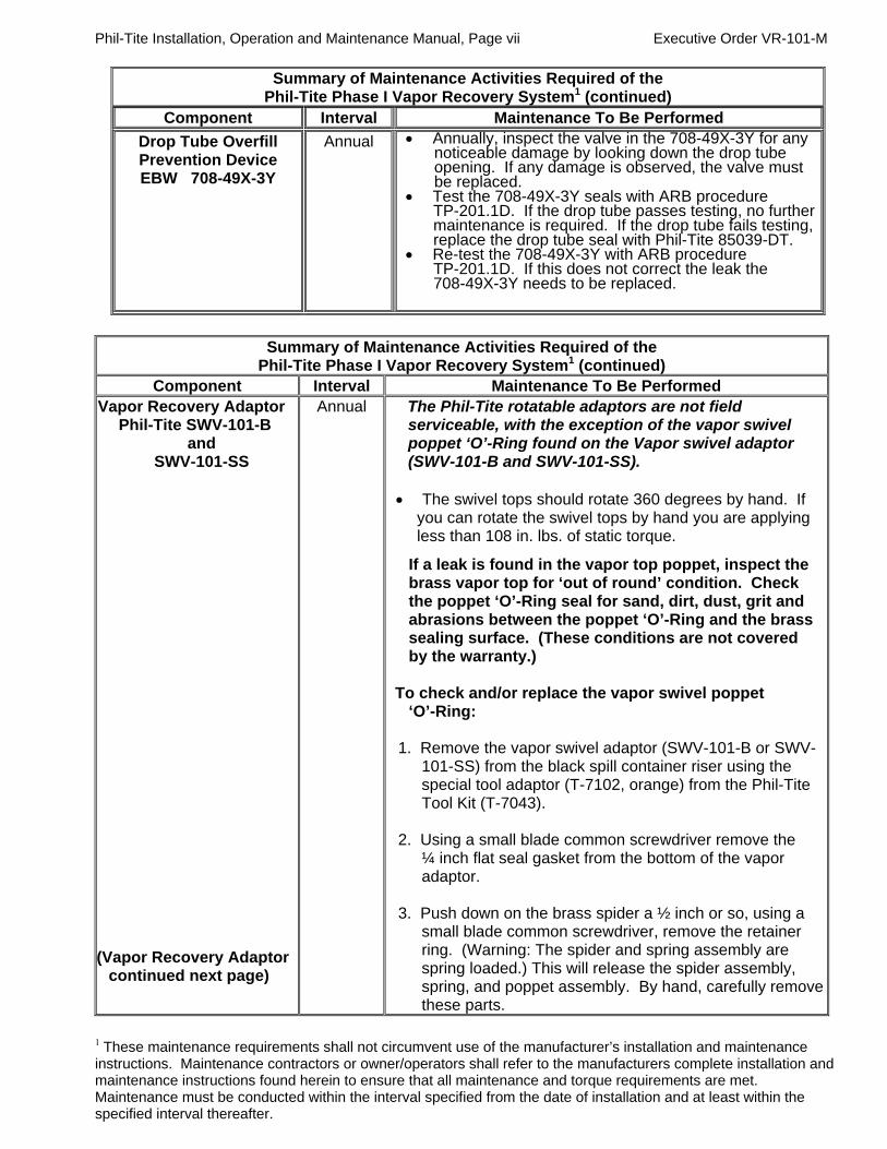
Drop Tube Overfill Prevention Device EBW 708-49X-3Y
Annual
Annually, inspect the valve in the 708-49X-3Y for any noticeable damage by looking down the drop tube opening. If any damage is observed, the valve must be replaced.
Test the 708-49X-3Y seals with ARB procedure TP-201.1D. If the drop tube passes testing, no further maintenance is required. If the drop tube fails testing, replace the drop tube seal with Phil-Tite 85039-DT.
Re-test the 708-49X-3Y with ARB procedure TP-201.1D. If this does not correct the leak the 708-49X-3Y needs to be replaced.
Summary of Maintenance Activities Required of the
Phil-Tite Phase I Vapor Recovery System1 (continued) Component Interval Maintenance To Be Performed
Vapor Recovery Adaptor Phil-Tite SWV-101-B
and SWV-101-SS
(Vapor Recovery Adaptor
continued next page)
Annual The Phil-Tite rotatable adaptors are not field serviceable, with the exception of the vapor swivel poppet ‘O’-Ring found on the Vapor swivel adaptor (SWV-101-B and SWV-101-SS).
The swivel tops should rotate 360 degrees by hand. If you can rotate the swivel tops by hand you are applying less than 108 in. lbs. of static torque.
If a leak is found in the vapor top poppet, inspect the brass vapor top for ‘out of round’ condition. Check the poppet ‘O’-Ring seal for sand, dirt, dust, grit and abrasions between the poppet ‘O’-Ring and the brass sealing surface. (These conditions are not covered by the warranty.)
To check and/or replace the vapor swivel poppet
‘O’-Ring:
1. Remove the vapor swivel adaptor (SWV-101-B or SWV-101-SS) from the black spill container riser using the special tool adaptor (T-7102, orange) from the Phil-Tite Tool Kit (T-7043).
2. Using a small blade common screwdriver remove the
¼ inch flat seal gasket from the bottom of the vapor adaptor.
3. Push down on the brass spider a ½ inch or so, using a
small blade common screwdriver, remove the retainer ring. (Warning: The spider and spring assembly are spring loaded.) This will release the spider assembly, spring, and poppet assembly. By hand, carefully remove these parts.
1 These maintenance requirements shall not circumvent use of the manufacturer’s installation and maintenance instructions. Maintenance contractors or owner/operators shall refer to the manufacturers complete installation and maintenance instructions found herein to ensure that all maintenance and torque requirements are met. Maintenance must be conducted within the interval specified from the date of installation and at least within the specified interval thereafter.

Phil-Tite Installation, Operation and Maintenance Manual, Page viii Executive Order VR-101-M
Summary of Maintenance Activities Required of the Phil-Tite Phase I Vapor Recovery System1 (continued)
Component Interval Maintenance To Be Performed Vapor Recovery Adaptor Phil-Tite SWV-101-B
and SWV-101-SS (Continued)
4. With the vapor poppet assembly removed, inspect the
poppet and poppet ‘O’-Ring for cuts, tears or damage. Replace the ‘O’-Ring if necessary. Before re-assembly spray a small amount of Silicon Spray on the poppet ‘O’-Ring. NOTE: DO NOT USE ANY TYPE OF OIL OR GREASE.
5. Re-assemble the vapor poppet, spring and brass spider
in the reverse order from which they were removed. 6. Install the retainer ring and actuate the poppet by hand,
making sure the assembly is secure and actuates properly.
7. Using a very small screwdriver, Install a new ¼ inch flat
seal (85039). Make sure the ¼ inch flat seal is seated against the sealing surface below the swivel adaptor threads.
8. Reinstall the SWV-101-B or SWV-101-SS vapor swivel
on the black spill container riser as described in the “Installation Instructions” and properly torque the swivel adaptor on the spill container riser between 50 and 75 ft. lbs.
Important: Apply an even coating of silicon based spray or a light coating of anti-seize compound to the male threads of the spill container riser and/or the swivel adaptor female threads. This will reduce the friction between these threads during installation and aid in removal of the swivel adaptor at a later date.
Tank Gauge Components
Morrison Brothers
305 series
Ever-Tite 4097 series
Veeder-Root 312020-952
EBW
90037 series
Annual
Visually inspect cap to see that it is not missing any seals
and is properly installed.
Whenever probe service is necessary, also inspect the service cap seal for damage and replace, if necessary,
at that time.
1 These maintenance requirements shall not circumvent use of the manufacturer’s installation and maintenance instructions. Maintenance contractors or owner/operators shall refer to the manufacturers complete installation and
1 These maintenance requirements shall not circumvent use of the manufacturer’s installation and maintenance instructions. Maintenance contractors or owner/operators shall refer to the manufacturers complete installation and

Phil-Tite Installation, Operation and Maintenance Manual, Page ix Executive Order VR-101-M maintenance instructions found herein to ensure that all maintenance and torque requirements are met. Maintenance must be conducted within the interval specified from the date of installation and at least within the specified interval thereafter.
Summary of Maintenance Activities Required of the Phil-Tite Phase I Vapor Recovery System1 (continued)
Component Interval Maintenance To Be Performed Spill Container Lid Phil-Tite 85011 (Spill Container Lid continued next page)
Periodically
Periodically
NOTE: DO NOT USE ANY PETROLEUM PRODUCTS ON THE WIPER SEAL, CAST IRON LID, OR THE STAINLESS STEEL SLEEVE. Clean the wiper seal using a clean rag and silicon spray.
The Wiper Seal must be free of any dirt, dust and/or film build up. If unable to properly clean, replace the wiper seal (SC-1513V).
Check the Wiper Seal for Flexibility: 1. Place your thumbs on the outer surface of the seal
approximately 4-6 inches apart. Push your thumbs toward each other. The wiper seal should have some movement between your thumbs. If there is no movement or flexibility, the wiper seal must be replaced and/or removed, cleaned, and rechecked.
2. Remove the wiper seal and clean the groove in the cast
iron lid of any dirt or dust build up by using a clean rag and silicon spray. The use of a blunt tool may be required to remove any build up.
3. Clean all surfaces of the wiper seal using a clean rag and
silicon spray. Any dirt or dust build up in the “U” section of the seal must be removed. The use of a wooden or plastic tipped instrument along with silicon spray may be required. If unable to properly clean, replace the wiper seal (SC-1513V).
Installing the Wiper Seal (SC-1513V) into the Groove of the Cast Iron Lid 1. Install the wiper seal in the cast iron lid groove with the
small (wiper) bulge facing outward and pointing upwards. Check the circumference of the installed seal for any twists or incorrect alignment of the seal in the groove. (Page 23 has a diagram of the seal and lid).
maintenance instructions found herein to ensure that all maintenance and torque requirements are met. Maintenance must be conducted within the interval specified from the date of installation and at least within the specified interval thereafter. 1 Component optional for vapor recovery system configuration; other requirements may apply.

Phil-Tite Installation, Operation and Maintenance Manual, Page x Executive Order VR-101-M
Summary of Maintenance Activities Required of the Phil-Tite Phase I Vapor Recovery System1 (continued)
Component Interval Maintenance To Be Performed Spill Container Lid Phil-Tite 85011
Periodically
Check the Stainless Steel Sleeve for Cleanliness
1. Clean the area of the stainless steel sleeve where the wiper seal makes contact with the sleeve. Using a clean rag and silicon spray, wipe this area free of any dirt, dust and/or film build up.
Reinsert the Lid with Wiper Seal over the Spill Container and into the Stainless Steel Sleeve.
Note: To ease installation use silicon spray on the exposed surface of the wiper seal and on the lip of the stainless steel sleeve where the wiper seal makes contact. Do not use any petroleum products.
1. Push down on the cast iron lid until it seats into the
stainless steel sleeve. 2. Hold the cast iron lid until it seats into the stainless
steel sleeve. 3. If the cast iron lid does not stay seated, wait five (5)
seconds then push down on the cast iron lid again. You will feel the cast iron lid go down and seat into the stainless steel sleeve.
4. Repeat this process until the cast iron lid stays seated in the stainless steel sleeve.
(End of maintenance table.)
1 The same torque settings apply for the (Gas/E85) components not shown in this figure.

Phil-Tite Installation, Operation and Maintenance Manual, Page xi Executive Order VR-101-M
Franklin Fueling Systems - Phil-Tite Phase I EVR Equipment Installation Check List
Installing Products per ARB Executive Order VR-101-M
Date: _____________
Site Location:(name) __________________________ Installing Contractor:(name __________________
Address ________________________________ Address _____________________________________
City/State ________________________________City/State___________________________________
Contact/Phone __________________________Contact/Phone ________________________________
Tank Number:__________ Product:___________________ Capacity:_________________
Tank Number:__________ Product:___________________ Capacity:_________________
Tank Number:__________ Product:___________________ Capacity:_________________
Installing Technician: (name): __________ __________
Technician Certification Number: ______________ Signature: _____ ___________ ____
1. Is all of the installed equipment for Phase I EVR listed in ARB Executive Order
(E.O.) VR-101-M? Note: All Phase I installed equipment must be listed in E.O. VR-101-M. See attached Exhibit 1 Listing Checklist, and mark/check off each item installed. 2. Have all tank risers been cut to the correct lengths and correctly installed into
the tank bungs using an approved pipe dope?
3. Do all tank risers that have a gasket/seal cap and/or spill containers have an
M/F 4X4 Riser Adaptor installed?
a. Are all M/F 4X4 Riser Adaptors installed onto tank risers using approved pipe dope and torque to _________________ ft. lbs.?
4. If a mechanical overfill prevention drop tube is installed, has the sealant
(epoxy) been allowed to cure a minimum of 4 hours before installation? 5. Fill Riser – Is the Drop Tube installed (under the spill container) using
Phil-Tite Special ‘O’ Ring (85039-DT) with the flared end on top of the M/F 4X4 Riser Adaptor?
Note: Phil-Tite 61SO-PT, EBW 708-49X-1Y and EBW 708-49X-3Y drop tubes with mechanical overfill prevention valves must be cut to the correct length and the upper end flared using Flaring Tool T-6100-FT before installing into the tank riser.
Yes/No Initials
Yes/No Initials
Yes/No Initials
Yes/No Initials
Yes/No Initials
Yes/No Initials

Phil-Tite Installation, Operation and Maintenance Manual, Page xii Executive Order VR-101-M
Franklin Fueling Systems - Phil-Tite Phase I EVR Equipment Installation Check List (con’t.)
Installing Products per ARB Executive Order VR-101-M
6. Are the Spill Containers installed onto the M/F 4X4 riser adaptors using approved anti- seize compound or silicon spray and torque to ____________________ ft. lbs.?
7. Are the Fill and Vapor Swivel Adaptors installed onto the spill container
risers using an approved anti-seizing compound or spray silicon and torque to___________ ft. lbs.?
8. Pressure Vacuum Vent Valve – Is there a P/V Vent valve installed on the top of each (Gas or Gas/E85) vent pipe (a maximum of three EVR P/V valves per GDF) or manifold?
a. P/V vent valve(s) torque to ____________________ ft. lbs. 9. Tank Gauge Port Cap and Adaptor – If installed,
a. Has an M/F 4X4 Riser Adaptor been installed onto the tank gauge riser using an approved pipe dope and torque to ____________________ ft. lbs.
b. Is the Tank Gauge Adaptor installed onto the M/F/ 4X4 riser adaptor using an approved anti-seize compound and torque to ___________________ ft. lbs.?
Yes/No Initials
Yes/No Initials
Yes/No Initials
Yes/No Initials
Yes/No
Initials
Yes/No Initials
Yes/No Initials

Phil-Tite Installation, Operation and Maintenance Manual, Page xiii Executive Order VR-101-M
Phil-Tite Phase I Vapor Recovery System Exhibit 1 Equipment Checklist On line below, write out what configuration you used. Follow the legend below for each series spill container (e.g. you would write out: 85100-F-15 if you had an 85000 series, 15 gallon replacement product spill container.) Configuration used: Equipment Manufacturer/Model Number (Gas/E85) = Identifies equipment approved for use with standard gasoline fuel blends and E85 (Gas) = Identifies equipment approved for use only with standard gasoline fuel blends Spill Container □Phil-Tite 85000 series (Gas/E85) □Phil-Tite 85000-1 series (Gas/E85) 85000 and 85000-1 series legend: 85W0X-YYY-ZZZ (85000 series) 85W0X-1YYY-ZZZ (85000-1 series) W represented by: □ 0 = preassembled spill container assembly □ 1 = replacement spill container X represented by: □ 0 = product spill container □ 1 = vapor spill container YYY represented by: □ 15 = 15-gallon capacity
□ EXT = external for sump configuration (not available for 85000-1 series)
□ NV = Vapor (replacement spill container) □ F = Product (replacement spill container) □ S = Stainless Steel (SS) Sleeve □ GS = Stainless Steel (SS) Sleeve and Gravel Shield ZZZ represented by: □ 15 = 15-gallon capacity
□ EXT = external for sump configuration (not available for 85000-1 series)
□ NV = Vapor (replacement spill container) □ F = Product (replacement spill container) □ S = Stainless Steel (SS) Sleeve □ GS = Stainless Steel (SS) Sleeve and Gravel Shield Spill Container Lid □Phil-Tite 85011 (not required with sump configuration lid) (Gas/E85) Debris Container □Phil-Tite PP-1005 TB (product) (not required) (Gas/E85) □Phil-Tite PP-1005 TBP (vapor) (not required) (Gas/E85) Product Adaptor □Phil-Tite SWF-100-B (Gas) □Phil-Tite SWF-100-SS (Gas/E85) Vapor Adaptor □Phil-Tite SWV-101-B (Gas) □Phil-Tite SWV-101-SS (Gas/E85) Riser Adaptor □Phil-Tite M/F 4X4 (Gas/E85) Riser Support Bracket □Phil-Tite M-1600 (Gas/E85)

Phil-Tite Installation, Operation and Maintenance Manual, Page xiv Executive Order VR-101-M
Exhibit 1 Listing Checklist (continued) Equipment Manufacturer/Model Number Dust Cap □Morrison Brothers 323C-0100ACEVR (vapor) (Gas/E85) □Morrison Brothers 305C-0100ACEVR (product) (Gas/E85) □OPW 1711T-EVR (vapor) (Gas/E85) □OPW 634TT-EVR (product) (Gas/E85) □OPW 634LPC (product) (Gas) □OPW 1711LPC (vapor) (Gas) □CompX CSP1-634LPC (product) (Gas) □CompX CSP3-1711LPC (vapor) (Gas) □CompX CSP2-634LPC (product) (Gas) □CompX CSP4-1711LPC (vapor) (Gas) □EBW 777-201-01 (product) (Gas) □EBW 777-201-02 (product) (Gas/E85) □EBW 304-301-XX (vapor) (Gas) XX indicates presence of security chain:
01 = no chain 02 = with chain
□EBW 304-301-YY(vapor) (Gas/E85) YY indicates presence of security chain:
03 = no chain 04 = with chain
Pressure/Vacuum □FFS PV-Zero (Gas/E85) Vent Valve □Husky 5885 (Gas) Tank Gauge Port □Ever-Tite 4097AGBR (threaded adaptor) (Gas) Components □Ever-Tite 4097AGMBRNL (adaptor) (Gas)
□Ever-Tite 4097MBR (double handle cap) (Gas)
□Veeder-Root 312020-952 (cap & adaptor) (Gas/E85) □Morrison Brothers 305XPA1100AKEVR (cap & adaptor kit) (Gas/E85) □Morrison Brothers 305-0200AAEVR (replacement adaptor) (Gas/E85) □Morrison Brothers 305XP-110ACEVR (replacement cap) (Gas/E85) □EBW 90037 (cap & adaptor) (Gas) □EBW 90037-E (cap & adaptor) (Gas/E85) Drop Tube Overfill □Phil-Tite 61SO-PT (Gas) Prevention Device1 □EBW 708-49X-1Y (Gas) □EBW 708-49X-3Y (Gas/E85) X represented by: 1 = 5 foot length upper drop tube section 2 = 10 foot length upper drop tube section Y represented by: 1 = 8 foot length bottom thread-on section drop tube 2 = 10 foot length bottom thread-on section drop tube Drop Tube1 □OPW 61-T (various lengths) (Gas) □EBW 782-204-3X2 (Gas/E85) (Note: 4 inch diameter tube) X represented by: 0 = 10 feet 2 = 12 feet Riser Offset1 □Phil-Tite M-6050 (Gas/E85)

Phil-Tite Installation, Operation and Maintenance Manual, Page xv Executive Order VR-101-M Double Fill1 □Phil-Tite (configuration only) (Gas/E85) Tank Bottom Protector1 □Phil-Tite TBP-3516 □Phil-Tite TBP-3516-E (Gas/E85)
1 Component optional for vapor recovery system configuration; other requirements may apply.
Phil-Tite Installation, Operation and Maintenance Manual, Page xvi Executive Order VR-101-M
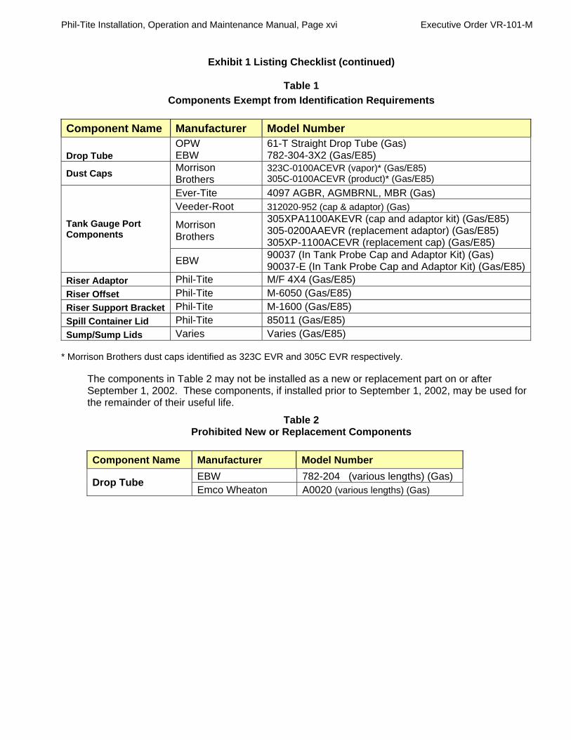
Exhibit 1 Listing Checklist (continued)
Table 1
Components Exempt from Identification Requirements
Component Name Manufacturer Model Number
Drop Tube OPW EBW
61-T Straight Drop Tube (Gas) 782-304-3X2 (Gas/E85)
Dust Caps Morrison Brothers
323C-0100ACEVR (vapor)* (Gas/E85) 305C-0100ACEVR (product)* (Gas/E85)
Tank Gauge Port Components
Ever-Tite 4097 AGBR, AGMBRNL, MBR (Gas) Veeder-Root 312020-952 (cap & adaptor) (Gas)
Morrison Brothers
305XPA1100AKEVR (cap and adaptor kit) (Gas/E85) 305-0200AAEVR (replacement adaptor) (Gas/E85) 305XP-1100ACEVR (replacement cap) (Gas/E85)
EBW 90037 (In Tank Probe Cap and Adaptor Kit) (Gas) 90037-E (In Tank Probe Cap and Adaptor Kit) (Gas/E85)
Riser Adaptor Phil-Tite M/F 4X4 (Gas/E85)
Riser Offset Phil-Tite M-6050 (Gas/E85)
Riser Support Bracket Phil-Tite M-1600 (Gas/E85)
Spill Container Lid Phil-Tite 85011 (Gas/E85)
Sump/Sump Lids Varies Varies (Gas/E85) * Morrison Brothers dust caps identified as 323C EVR and 305C EVR respectively.
The components in Table 2 may not be installed as a new or replacement part on or after September 1, 2002. These components, if installed prior to September 1, 2002, may be used for the remainder of their useful life.
Table 2 Prohibited New or Replacement Components
Component Name Manufacturer Model Number
Drop Tube EBW 782-204 (various lengths) (Gas) Emco Wheaton A0020 (various lengths) (Gas)
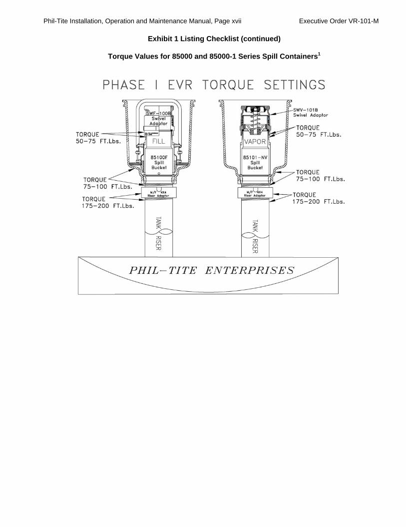
Phil-Tite Installation, Operation and Maintenance Manual, Page xvii Executive Order VR-101-M
Exhibit 1 Listing Checklist (continued)
Torque Values for 85000 and 85000-1 Series Spill Containers1

Phil-Tite Installation, Operation and Maintenance Manual, Page xviii Executive Order VR-101-M
Phil-Tite Phase I Vapor Recovery System
Installation, Operation and Maintenance Manual
Table of Contents Equipment Manufacturer/Model Number Figure Page Summary of Maintenance Activities Required of the Phil-Tite Phase I Vapor Recovery System ......................................................................... iii Installation Check List ……………………………………………………………………… xi Exhibit 1 Equipment Checklist ................................................................................................ xiiii Components Exempt from Identification Requirements ...................................................... xvi Prohibited New or Replacement Components ...................................................................... xvi Torque Values for 85000 and 85000-1 Series Spill Containers ........................................... xviii Table of Contents .................................................................................................................... xvii Typical Installation (Product) with 61SO-PT ................................................ A-1 ...................... 1 Typical Installation (Product) with EBW Autolimiter II® 708-49X-1Y or Autolimiter II® 708-49X-3Y .................................................................... A-2 ...................... 2 Typical Installation (Vapor Side) ................................................................... A-3 ...................... 3 Spill Containers - Phil-Tite 85000 series and 85000-1 series Phil-Tite 85000-1 Series Spill Container Installation Instructions ....... B-1 ...................... 4 New UST Installation and/or UST’s Being Upgraded .......................... ............................ 4
Replacing Existing 85000 Series with 85000-1 Series ....................... ............................ 5
85000-1 Series Spill Container Installation ............................................ ............................ 6
Diagram of 85000-1 Series Spill Container Installation Guide ............. B-2 ...................... 8
85100-F and 85101-NV Series Spill Container Installation ................... ............................ 9
Existing 85000 series (EVR upgrades) ................................................... ....................... 10
Spill Container 5 Gallon Capacity and Height Spacer ........................ B-3 .................... 12
Diagram of 85000 Spill Container Installation Guide ........................... B-4 .................... 13
Continued on next page.

Phil-Tite Installation, Operation and Maintenance Manual, Page xix Executive Order VR-101-M
Table of Contents (continued)
Equipment Manufacturer/Model Number Figure Page 85000-EXT Series Spill Container Installing a Watertight Fiberglass Platform under a Manway Cover ............................................................................ .......................... 14 Retro Fitting Previous Spill Container Installation Under A Composite Manway Cover Using a Phil-Tite ‘Above the Spill Container’ Fiberglass Platform 15
Diagram of Measurements for 85000-EXT series installation .............. B-5 .................... 16
Figure of Typical Manway Cover Dimensions ...................................... B-6 .................... 16
Installing a 42” Watertight Fiberglass Platform under a 42” Composite
Manway Cover with 85000-EXT Spill Containers ................................... .......................... 18
85000-EXT Series Spill Container Installation ............................................. .......................... 20 Drain Valve 85400 (included in each product spill container assembly) ......... B-7 .................... 21 Phil-Tite 85011 Cast Iron Spill Container Lid ............................................... B-8 .................... 23 Installation and maintenance of 85011 ...................................................... B-8a .................. 24 Debris Container Phil-Tite PP-1005 TB (product)(optional) ................................................... B-9 .................... 25 Phil-Tite PP-1005 TBP1 (vapor)(optional) .................................................. B-9 .................... 25 Product Adaptor Phil-Tite SWF-100-series Installation Instructions ..................................... C-1 .................... 26 Phil-Tite SWF-100-series Maintenance Instructions .................................. C-2 .................... 27 Vapor Adaptor Phil-Tite SWV-101-series Installation Instructions ..................................... C-1 .................... 26 Phil-Tite SWV-101-series Maintenance Instructions .................................. C-2 .................... 27 Riser Adaptor Phil-Tite M/F 4X4 Installation Instructions .................................................. D-1 .................... 29 Diagram of M/F 4x4 for use with 85000 Series Spill Container ................. D-2 .................... 30 Diagram of M/F 4x4 for use with 85000-1 Series Spill Container .............. D-3 .................... 31 Dust Caps Morrison Brothers 323C-0100ACEVR (vapor) ........................................... E-1 .................... 32 Morrison Brothers 305C-0100ACEVR (product) ........................................ E-1 .................... 32 OPW 1711T-EVR (vapor) .......................................................................... E-2 .................... 33 OPW 634TT-EVR (product) ....................................................................... E-2 .................... 33
EBW 304-301-XX or 304-301-YY (vapor) .................................................. E-3 .................... 34 EBW 777-201-01 or 777-201-02 (product) ................................................ E-3 .................... 34 Continued on next page.
1 Component optional for vapor recovery system configuration; other requirements may apply.

Phil-Tite Installation, Operation and Maintenance Manual, Page xx Executive Order VR-101-M
Table of Contents (continued) Equipment Manufacturer/Model Number Figure Page OPW 634LPC (product) ............................................................................. E-4 .................... 35 OPW 1711LPC (vapor) .............................................................................. E-4 .................... 35 CompX CSP1-634LPC or CSP3-634LPC (product) .................................. E-5 .................... 36 CompX CSP2-1711LPC or CSP4-1711LPC (vapor) ................................. E-5 .................... 36 Pressure/Vacuum Vent Valve FFS PV-Zero .............................................................................................. F-1 ..................... 37 Husky 5885 ................................................................................................ F-2 ..................... 49 Tank Gauge Port Components
Ever-Tite 4097AGBR (threaded adaptor) .................................................. G-1 ................... 52 Ever-Tite 4097AGMBRNL (adaptor) .......................................................... G-1 ................... 52 Ever-Tite 4097MBR (double handled cap) ................................................ G-1 ................... 52
Veeder-Root 312020-952 (cap & adaptor) ................................................. G-2 ................... 53 Morrison Brothers 305XPA1100AKEVR (cap and adaptor kit) .................. G-3 .................... 54 Morrison Brothers 305-0200AAEVR (replacement adaptor) .................... G-3 .................... 54 Morrison Brothers 305XP-110ACEVR (replacement cap) ........................ G-3 .................... 54
EBW 90037 and 90037-E In-Tank Probe Cap and Adaptor Kit ................. G-4 .................... 55
Drop Tube1
OPW 61-T Straight Drop Tube ................................................................... H-1 .................... 56 EBW 782 Straight Drop Tube H-2 57 Drop Tube Overfill Prevention Device1 Phil-Tite 61SO-PT ...................................................................................... J-1 ..................... 58 Measurement Work Sheet to Determine the Drop Tube Lengths for 61SO–PT–(X) ............................................................. J-1a ................... 61 EBW Autolimiter II® 708-49X- series ......................................................... J-2 ..................... 70 Measurement Work Sheet to Determine the Drop Tube Lengths for EBW Autolimiter II® 708-49X- series .......................... J-2a ................... 73 Tank Bottom Protector Phil-Tite TBP-3516 series .......................................................................... J-3 ..................... 82 Riser Offset1 Phil-Tite M-6050 Examples ........................................................................ K-1 .................... 83 Riser Support Bracket Phil-Tite M-1600 ......................................................................................... K-2 .................... 84 Continued on next page.

Phil-Tite Installation, Operation and Maintenance Manual, Page xxi Executive Order VR-101-M
Table of Contents (continued) Equipment Manufacturer/Model Number Figure Page Double Fill1 Phil-Tite (configuration only) ...................................................................... L-1 ..................... 87 Manway Cover with Platform1 Example diagram ....................................................................................... L-2 ..................... 88 FFS/Phil-Tite Phase I Installation & Removal Tool Kit T-7043 / T-7043-1 ...................................................................................... L-3 ..................... 89
Figure of T-7043 Toolkit ............................................................................. L-3a ................... 90
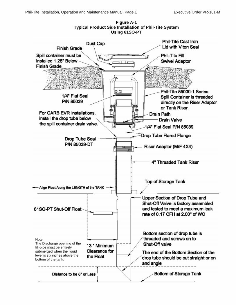
Phil-Tite Installation, Operation and Maintenance Manual, Page 1 Executive Order VR-101-M
Figure A-1 Typical Product Side Installation of Phil-Tite System
Using 61SO-PT
Note: The Discharge opening of the fill-pipe must be entirely submerged when the liquid level is six inches above the bottom of the tank.

Phil-Tite Installation, Operation and Maintenance Manual, Page 2 Executive Order VR-101-M
Figure A-2 Typical Product Side Installation of Phil-Tite System Using
FFS Autolimiter II® 708-49X- Series
Note: The Discharge opening of the fill-pipe must be entirely submerged when the liquid level is six inches above the bottom of the tank.

Phil-Tite Installation, Operation and Maintenance Manual, Page 3 Executive Order VR-101-M
Figure A-3
Typical Vapor Recovery Side Installation Using Phil-Tite System

Phil-Tite Installation, Operation and Maintenance Manual, Page 4 Executive Order VR-101-M
Figure B-1 Phil-Tite 85000 series and 85000-1 series Product and Vapor Spill Containers
Franklin Fueling Systems – Phil-Tite
Phil-Tite 85000-1 Series Spill Containers – Fill and Vapor Installation Instructions
Introduction Phil-Tite Spill Containers (Fill and Vapor) are designed to provide easy installation and/or removal of the spill container without the need for timely excavation, cutting concrete or disassembly of secondary containment covers. Phil-Tite’s drain valves drain directly into the tank, providing a fast and complete removal of excess liquid spilled during a product delivery operation while maintaining a reliable seal that is vapor and liquid tight, eliminating leaks into the environment. All Phil-Tite’s Spill Containers have straight machined threads (female threads where the spill container screws onto the riser adaptor.) All Spill Containers are shipped completely assembled and ARB Phase I EVR Certified. No assembly is required. The new 85000-1 Series Spill Container can be used as a direct replacement for a correctly installed 85000 series EVR Spill Container without cutting concrete or changing the tank riser. Note: On EVR certified systems the drop tube is installed below the drain valve and under the fill spill container.
For New UST Installation and/or UST’s being Upgraded Step 1 – Determining the Correct Riser Length for Spill Container Installation
A. Method 1 - Cut and thread your steel tank riser to allow approximately 18 1/8 inches (Fill riser), and/or 18 inches (Vapor riser) from top of the tank riser to finish grade. This measurement assumes an M/F 4X4 Riser Adaptor will be installed. Also this measurement will allow the water-tight cast iron lid to seat properly into the stainless steel sleeve when the spill container is installed. See Figure titled “85000-1 Series Spill Container Installation Guide” in this section.
B. Method 2 - With the M/F 4X4 Riser Adaptor installed onto the Tank Riser you should have 16 3/8 inches (Fill), and 16 ¼ inches (Vapor) measured from the top of the M/F 4X4 riser adaptor to finish grade or top of the diamond plate manway cover. This measurement will allow the water tight cast iron lid to seat properly into the stainless steel sleeve. See Figure titled “85000-1 Series Spill Container Installation Guide” in this section.
C. Method 3 - Using a tape measure, measure from top of the tank to finish grade and/or top of the manway cover. This is measurement “A”. For 85000-1 Fill Spill Container subtract 18 1/8 inches from measurement “A” to equal “xxx”. “A” – 18 1/8 inches = “xxx”. For the 85000-1 Vapor spill containers subtract 18 inches from “A”. The results are the length of your risers measured from the top of the tank. Cut and thread one end of your 4 inch riser and dry fit it into the tank bung. Measure your riser (installed into the tank bung) from top of tank to the dimension above, mark your riser. Cut this riser on the mark made above and thread this end. See Figure titled “85000-1 Series Spill Container Installation Guide” in this section.
Step 2 – Dry Fit All Components
A. Dry fit your riser to verify your measurements. After you have dry fit all components and are satisfied with your measurements, apply an approved fuel resistant, non hardening thread sealant (pipe dope) to the NPT threads on both ends of the tank risers.
Step 3 – Install Tank Risers
A. Install and torque the tank risers into the tank bungs.
(Continue to appropriate Spill Container Instructions in this document.)

Phil-Tite Installation, Operation and Maintenance Manual, Page 5 Executive Order VR-101-M
For Replacing Existing Phil-Tite 85000 series with
85000-1 series Spill Containers
Step 1 - Determining the Correct Tank Riser Length for Spill Container Installation
A. Existing tank risers with NO M/F 4X4 riser adaptor installed. – Using a tape measure, measure from the top of your riser to finish grade and/or top of the manway cover. Record this measurement. For Fill spill containers this measurement should be 18 1/8 inches from the top of the riser to finish grade. For Vapor spill containers this measurement should be 18 inches from top of riser to finish grade. If these measurements are less than the above measurements you must shorten your riser to meet these measurements. These measurements allow for an M/F 4X4 Riser Adaptor to be installed on top of the tank riser before the spill container is installed. If you are not installing an M/F 4X4, add 1 ¾ inches to your riser length.
Remember, from finish grade to the top of the M/F 4X4 adaptor installed on the riser should be 16 and 3/8 inches for Fill spill containers. See Figure titled “85000-1 Series Spill Container Installation Guide” in this section.
B. Existing tank risers with M/F 4X4 riser adaptor installed – Using a tape measurer, measure from
the top of the M/F 4X4 riser adaptor to finish grade and/or to the top of the stainless steel sleeve. Record this measurement. For Fill Spill Containers this measure must be greater than or equal to 16 3/8 inches (16 3/8” - 20 1/8”), and for Vapor spill containers this measurement must be greater than or equal to 16 ¼ inches (16 1/4” - 20”).
C. If your existing riser is too long, there are several possible ways you can shorten them. Some
possible methods are:
1) Remove the nipple that would have been installed prior to 2001 (pre-EVR Installation) and install a shorter nipple. Especially helpful for direct buried spill containers.
2) For multi-port systems, remove the existing riser(s) and install the correct length riser(s).
Use an M-1600 riser support bracket to maintain alignment 16 inches on center between the fill and vapor riser.
3) For direct buried risers with no nipple and coupler you may be able to excavate down to
tank top using a 10-11 inches OD PVC pipe placed over the 4 inch riser. Then remove the backfill material as you lower the pipe down over the riser. When you have reached the tank top, remove the 4 inch riser and install the correct length 4 inch riser per the following Steps 2 & 3. After you have installed the tank riser gradually remove the 10-11 inches OD PVC pipe as you back fill the space between the 4 inch riser and the 10-11 inches OD PVC pipe.
Step 2 - Dry fit your riser to verify your measurements.
A. After you have dry fit all components and are satisfied with your measurements, apply an approved fuel resistant, non hardening thread sealant (pipe dope) to the NPT threads on both ends of the tank risers.
Step 3 - Install the correct length tank risers
Install and torque the 4 inch tank risers into the tank bungs.
(Continue to appropriate Spill Container Instructions in this document.)
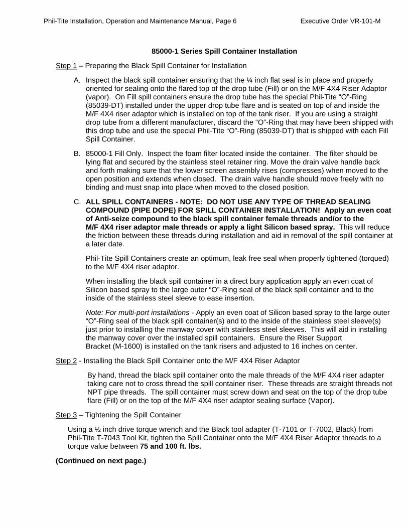
Phil-Tite Installation, Operation and Maintenance Manual, Page 6 Executive Order VR-101-M
85000-1 Series Spill Container Installation
Step 1 – Preparing the Black Spill Container for Installation
A. Inspect the black spill container ensuring that the ¼ inch flat seal is in place and properly oriented for sealing onto the flared top of the drop tube (Fill) or on the M/F 4X4 Riser Adaptor (vapor). On Fill spill containers ensure the drop tube has the special Phil-Tite “O”-Ring (85039-DT) installed under the upper drop tube flare and is seated on top of and inside the M/F 4X4 riser adaptor which is installed on top of the tank riser. If you are using a straight drop tube from a different manufacturer, discard the “O”-Ring that may have been shipped with this drop tube and use the special Phil-Tite “O”-Ring (85039-DT) that is shipped with each Fill Spill Container.
B. 85000-1 Fill Only. Inspect the foam filter located inside the container. The filter should be lying flat and secured by the stainless steel retainer ring. Move the drain valve handle back and forth making sure that the lower screen assembly rises (compresses) when moved to the open position and extends when closed. The drain valve handle should move freely with no binding and must snap into place when moved to the closed position.
C. ALL SPILL CONTAINERS - NOTE: DO NOT USE ANY TYPE OF THREAD SEALING COMPOUND (PIPE DOPE) FOR SPILL CONTAINER INSTALLATION! Apply an even coat of Anti-seize compound to the black spill container female threads and/or to the M/F 4X4 riser adaptor male threads or apply a light Silicon based spray. This will reduce the friction between these threads during installation and aid in removal of the spill container at a later date.
Phil-Tite Spill Containers create an optimum, leak free seal when properly tightened (torqued) to the M/F 4X4 riser adaptor.
When installing the black spill container in a direct bury application apply an even coat of Silicon based spray to the large outer “O”-Ring seal of the black spill container and to the inside of the stainless steel sleeve to ease insertion.
Note: For multi-port installations - Apply an even coat of Silicon based spray to the large outer “O”-Ring seal of the black spill container(s) and to the inside of the stainless steel sleeve(s) just prior to installing the manway cover with stainless steel sleeves. This will aid in installing the manway cover over the installed spill containers. Ensure the Riser Support Bracket (M-1600) is installed on the tank risers and adjusted to 16 inches on center.
Step 2 - Installing the Black Spill Container onto the M/F 4X4 Riser Adaptor
By hand, thread the black spill container onto the male threads of the M/F 4X4 riser adapter taking care not to cross thread the spill container riser. These threads are straight threads not NPT pipe threads. The spill container must screw down and seat on the top of the drop tube flare (Fill) or on the top of the M/F 4X4 riser adaptor sealing surface (Vapor).
Step 3 – Tightening the Spill Container
Using a ½ inch drive torque wrench and the Black tool adapter (T-7101 or T-7002, Black) from Phil-Tite T-7043 Tool Kit, tighten the Spill Container onto the M/F 4X4 Riser Adaptor threads to a torque value between 75 and 100 ft. lbs.
(Continued on next page.)

Phil-Tite Installation, Operation and Maintenance Manual, Page 7 Executive Order VR-101-M
85000-1 Series Spill Container Installation (continued)
Step 4 – Final Installation
Upon final installation, check the measurement from the top of the black spill container to the top of the stainless steel sleeve at finish grade. Ensure there is at least 1 ¼ inches of clearance (more is OK) from the top of the black spill container to the top of the stainless steel sleeve at finish grade. This will allow for the water tight cast iron lid to fit properly and ensure that the spill container and tank riser are not in direct contact with the cast iron lid. This ensures the concrete with manway cover are not load bearing onto the tank fill and vapor risers.
Step 5 – Drain Valve Testing
Test the drain valve assembly as described in ARB procedure TP-201.1D.
Step 6 – After Spill Container Installation
The spill container is now ready for the installation of the rotatable (swivel) adaptor and dust cap. Install the fill and/or vapor swivel adaptor using the SWF-100 series/SWV-101 series Installation Instructions.

Phil-Tite Installation, Operation and Maintenance Manual, Page 8 Executive Order VR-101-M
Figure B-2
Diagram of 85000-1 Spill Container Installation Guide

Phil-Tite Installation, Operation and Maintenance Manual, Page 9 Executive Order VR-101-M
Franklin Fueling Systems - Phil-Tite
Phil-Tite 85100-F and 85101-NV Series Spill Containers Installation Instructions
Introduction
Phil-Tite Spill Containers (Fill and Vapor) are designed to provide easy installation and/or removal of the spill container without the need for timely excavation, cutting concrete or disassembly of secondary containment covers. Phil-Tite’s drain valves drain directly into the tank, providing a fast and complete removal of excess liquid spilled during a product delivery operation while maintaining a reliable seal that is vapor and liquid tight, eliminating leaks into the environment. All Phil-Tite’s Spill Containers have straight machined threads (female threads where the spill container screws onto the riser adaptor.) All Spill Containers are shipped completely assembled and ARB Phase I EVR Certified. No assembly is required. Note: On EVR certified systems the drop tube is installed below the drain valve and under the fill spill container. Installation: Step 1 – Determining the Correct Riser Length for New or Upgraded UST’s to Achieve 5 Gallon Capacity (California State Water Resources Control Board requirement. See Local Guidance Letter 166 at www.waterboards.ca.gov/ust/leak_prevention/lgs/index.html or call (916) 341-5752 or (916) 341-5782).
A. Method 1 - Cut and thread your steel tank riser to allow approximately 17 ¼ inches (Fill);
17 inches (Vapor) from top of the M/F 4X4 adaptor to finish grade or top of the diamond plate manway cover. This measurement will achieve 5 gallons capacity. See Figure titled “85000 Series Spill Container Installation Guide” in this section.
Ensure there is adequate clearance to provide at least 4 7/16 inches to 4 ½ inches between the top of the Spill Container and the top of the stainless steel sleeve once final installation is complete. Use a tape measure to verify. For ease of installation use the Styro-foam spacer that is shipped with each 85100-F and 85101-NV Spill container. For 5 gallon capacity use this spacer to correctly set the depth of the black spill container below grade in the stainless steel sleeve. See Figure titled “Spill Container 5 Gallon Capacity and Height Spacer” in this section.
B. Method 2 - Using a tape measure, measure from top of the tank to finish grade or top of the
manway cover. This is measurement “A”. For Fill Spill Containers (85100-F) subtract 19 inches from measurement “A” to equal “xxx”. “A” – 19 inches = “xxx”. For vapor spill containers (85101-NV) subtract 18 ¾ inches from “A”. The result is the length of your riser measured from the top of the tank. Cut and thread one end of your 4 inch riser and dry fit it into the tank bung. Measure your riser (installed into the tank bung) from top of tank to the dimension above, mark your riser. Cut this riser on the mark made above and thread this end. See Figure titled “85000 Series Spill Container Installation Guide” in this section.
Step 2 – Dry Fit All Components
Dry fit your riser to verify your measurements. After you have dry fitted all components and are satisfied with your measurements, apply an approved fuel resistant, non hardening thread sealant (pipe dope) to the NPT threads on both ends of the tank risers.
Step 3 – Install Tank Risers
Install and torque the tank risers into the tank bungs.
(Continue to appropriate Spill Container Instructions in this section.)

Phil-Tite Installation, Operation and Maintenance Manual, Page 10 Executive Order VR-101-M
For Existing Phil-Tite 85000 series Spill Containers (EVR upgrades)
Step 1 - Determining the Correct Tank Riser length for existing Phil-Tite 85000 series Spill Containers (EVR upgrades, etc.) to achieve 5 Gallon Capacity (California State Water Resources Control Board requirement. Call (916) 341-5752 or (916) 341-5782 or see Local Guidance Letter 166 at www.waterboards.ca.gov/ust/leak_prevention/lgs/index.html.
A. Existing tank risers with NO M/F 4X4 riser adaptor installed. – Using a tape measure, measure from the top of your tank riser to finish grade and/or top of the manway cover. Record this measurement. For Fill spill containers this measurement should be 19 inches from the top of the riser to finish grade. For vapor spill containers this measurement should be 18 ¾ inches from top of riser to finish grade. If these measurements are less than the above measurements you must shorten your riser to meet these measurements. These measurements assume an M/F 4X4 Riser Adaptor will be installed on top of the tank riser before the spill container is installed. If not, add 1 ¾ inches to your riser length.
Remember, from finish grade to the top of the M/F 4X4 adaptor installed on the tank riser should be 17 1/4 inches for Fill spill containers to meet 5 gallon capacity requirements. See Figure titled “85000 Series Spill Container Installation Guide” in this section.
B. If your existing riser is too long, there are several possible ways you can shorten them. Some
possible methods are:
1) Remove the nipple that would have been installed prior to 2001 (pre-EVR Installation) and install a shorter nipple. Especially helpful for direct buried spill containers.
2) For multi-port systems, remove the existing riser(s) and install the correct length riser(s).
Use an M-1600 riser support bracket to maintain alignment between the fill and vapor riser.
3) For direct buried risers with no nipple and coupler you may be able to excavate down to
tank top using a 10-11 inch OD PVC pipe placed over the 4 inch riser. Then remove the backfill material as you lower the pipe down over the riser. When you have reached tank top remove the 4 inch riser and install the correct length 4 inch riser per the following Steps 2 & 3. After you have installed the tank riser gradually remove the 10-11 inch OD PVC pipe as you back fill the space between the 4 inch riser and the 10-11 inch OD PVC pipe.
Step 2 - Dry fit your riser to verify your measurements.
After you have dry fit all components and are satisfied with your measurements, apply an approved fuel resistant, non hardening thread sealant (pipe dope) to the NPT threads on both ends of the tank risers.
Step 3 - Install the correct length tank risers
Install and torque the 4 inch tank risers into the tank bungs.
(Continue to appropriate Spill Container Instructions in this section.)

Phil-Tite Installation, Operation and Maintenance Manual, Page 11 Executive Order VR-101-M
85000 Series Spill Container Installation
Step 1 – Preparing the Black Spill Container for Installation A. Inspect the black spill container ensuring that the ¼ inch flat seal is in place and properly oriented
for sealing onto the flared top of drop tube (Fill) or on the M/F 4X4 Riser Adaptor (vapor). On Fill spill containers ensure the drop tube has the special Phil-Tite seal (85039-DT) installed under the upper drop tube flare and is seated on top of and inside the M/F 4X4 riser adaptor which is installed on top of the tank riser. If you are using a straight drop tube from a different manufacturer, discard the seal that may have been shipped with this drop tube and use the special Phil-Tite seal (85039-DT) that is shipped with each Fill Spill Container.
B. 85100-F Fill Only. Inspect the foam filter located inside the container. The filter should be lying flat
and secured by the stainless steel retainer ring. Move the drain valve handle back and forth making sure that the lower screen assembly rises (compresses) when moved to the open position and extends when closed. The drain valve handle should move freely with no binding and snap into place when moved to the closed position.
C. NOTE: DO NOT USE ANY TYPE OF THREAD SEALING COMPOUND FOR SPILL CONTAINER
INSTALLATION! Apply an even coat of Silicon based spray to the black spill container female threads and to the M/F 4X4 riser adaptor male threads or apply a light coating of anti-seize compound. This will reduce the friction between these threads during installation and aid in removal of the spill container at a later date.
Phil-Tite Spill Containers create an optimum, leak free seal when properly tightened (torqued) to the tank riser. When installing the black spill container in a direct bury application apply an even coat of Silicon based spray to the large outer wiper seal of the black spill container and to the inside of the stainless steel sleeve to ease insertion. Note: For multi-port installations - Apply an even coat of Silicon based spray to the large outer wiper seal of the black spill container and to the inside of the stainless steel sleeve just prior to installing the manway cover with stainless steel sleeves. This will aid in installing the manway cover over the installed spill containers. Ensure the Riser Support Bracket (M-1600) is installed on the tank risers and adjusted to 16 inches on center.
(Continued on next page.)

Phil-Tite Installation, Operation and Maintenance Manual, Page 12 Executive Order VR-101-M
85000 Series Spill Container Installation (continued)
Step 2 - Installing the Black Spill Container onto the M/F 4X4 Riser Adaptor
By hand, thread the black spill container onto the male threads of the M/F 4X4 riser adapter taking care not to cross thread the spill container riser. These threads are straight threads not NPT pipe threads. The spill container must screw down and seat on the top of the drop tube flare (Fill) or on the top of the M/F 4X4 riser adaptor sealing surface (Vapor).
Step 3 – Tightening the Spill Container
Using a ½ inch drive torque wrench and the special tool adapter (T-7101 or T-7002, Black) from Phil-Tite T-7043 Tool Kit, tighten the Spill Container onto the M/F 4X4 Riser Adaptor threads to a torque value between 75 and 100 ft. lbs.
Step 4 – Final Installation
Upon final installation, check the measurement from the top of the black spill container to the top of the stainless steel sleeve at finish grade. Ensure there is at least 4-7/16 inches to 4 ½ inches from the top of the black spill container to the top of the stainless steel sleeve at finish grade to achieve 5 gallons capacity.
Step 5 – Drain Valve Testing
Test the drain valve assembly as described in ARB procedure TP-201.1D.
Step 6 – After Spill Container Installation
The spill container is now ready for the installation of the rotatable (swivel) adaptor and dust cap. Install the fill and/or vapor swivel adaptor using the SWF-100 series/SWV-101 series Installation Instructions found in this IOM.
To Achieve 5 gallons Capacity:
Step 7 - Insert the Styro-foam Spacer into the stainless steel sleeve on top of the Black Spill Container.
Step 8 - With the Styro-foam Spacer resting on top of the black spill container, the top of the spacer should be at or below the rim under the Cast Iron Lid. See the arrow in the photo.
Step 9 - During construction, the Spacer should be left in place with the cast iron lid installed to provide the correct height with finish grade until concrete has been poured and set.
Figure B-3 Spill Container 5 Gallon Capacity and Height Spacer
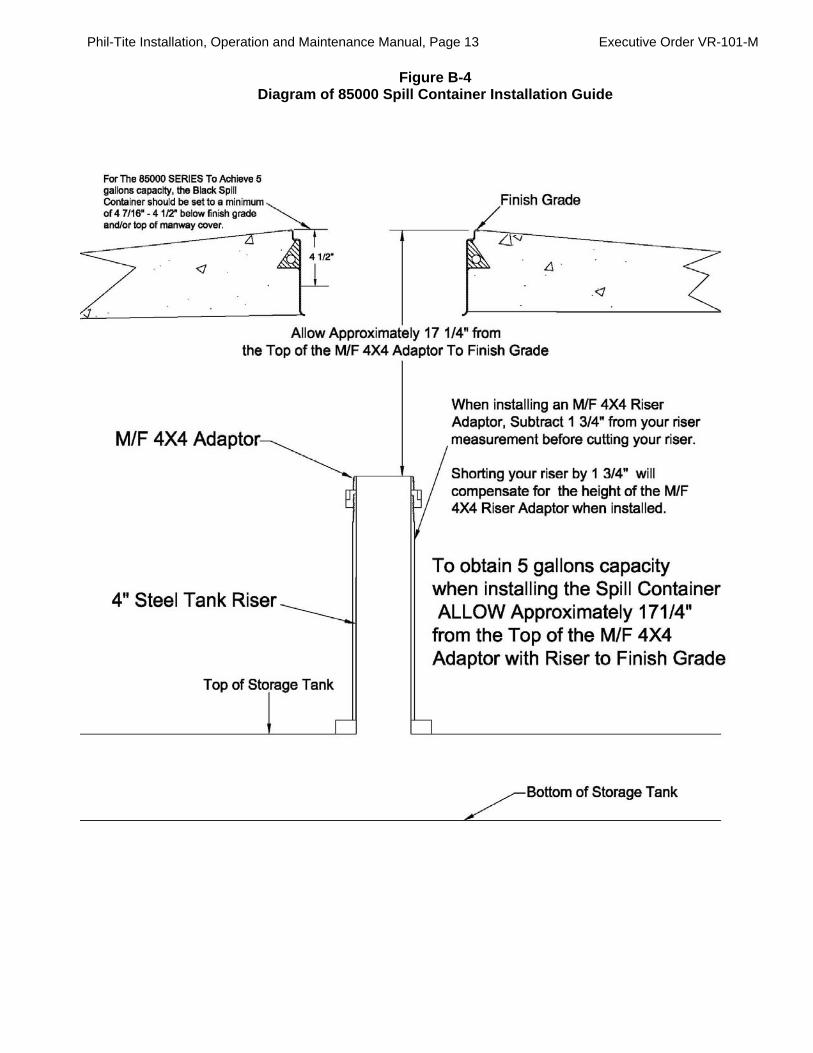
Phil-Tite Installation, Operation and Maintenance Manual, Page 13 Executive Order VR-101-M
Figure B-4 Diagram of 85000 Spill Container Installation Guide

Phil-Tite Installation, Operation and Maintenance Manual, Page 14 Executive Order VR-101-M
Franklin Fueling Systems - Phil-Tite
85000-EXT Series Spill Containers Installed Using a Fiberglass Platform under a Composite Manway Cover
Installation Instructions
Introduction
Many Gasoline Dispensing Facilities (GDF’s) desire a single solid light weight manway cover over the location where the UST’s fuel delivery/transfer spill and overfill protection equipment is installed inside a UST sump. This concept uses a single exterior cover to help keep water intrusion and dirt out and provide higher security in accessing the UST’s. The manway covers that are used for this configuration are Composite manway covers that are removed by using a single tool without having to bend over. There are rain tight models and watertight models. The manway cover is removed (using a single point removal tool) to access the spill containers during bulk fuel deliveries. Below the manway cover is a fiberglass refueling platform that is installed either above the spill containers or under the spill containers and on top of the UST sump reducer/corbel. During bulk fuel transfers the driver removes the manway cover and connects the tanker truck fuel hoses with adaptors to the appropriate spill container while standing on the refueling platform. In the event of a spill during delivery, the spill container and the UST Sump are available to contain the spill. Phil-Tite’s 85000-EXT series 5 gallon capacity Spill Containers (Fill and Vapor) were designed for this type of application using one of three Phil-Tite fiberglass platforms designed for this application. These spill containers and fiberglass platforms were first certified and listed in ARB Executive Order VR-101-C dated September 16, 2003. The components of the 85000-EXT (extended) series spill containers are the same as the 85000 series spill containers. A 3 X 15 inches diameter extension has been added to the 85000 series spill container in order for it to contain 5 gallons of liquid without the use of the stainless steel sleeve and is installed as a stand alone spill container without a cover. The Phil-Tite’s drain valve drains liquid directly into the tank, providing a fast and complete removal of excess liquids spilled during a product delivery operation while maintaining a reliable seal that is vapor and liquid tight, eliminating leaks into the environment. Phil-Tite’s Spill Containers have straight machined threads (female threads where the spill container screws onto the tank riser adaptor.) All Spill Containers are shipped completely assembled and ARB EVR Certified. No assembly is required. Note: On EVR certified systems, the drop tube is installed below the drain valve and under the fill spill container.

Phil-Tite Installation, Operation and Maintenance Manual, Page 15 Executive Order VR-101-M
Retro Fitting Previous Spill Container Installation Under A Composite Manway Cover Using a Phil-Tite ‘Above the Spill Container’ Fiberglass Platform
85000-EXT–CA-2-AB-EVR-PKG – Above the Spill Container Fiberglass Platform Package Step 1 – Determining The Correct Riser Length for an ‘Above The 85000-EXT Spill Containers’ Fiberglass Platform. Assuming that:
36” Composite Manway Cover is already installed; and
the 85000-EXT Spill Container has an installed length of 15 ¾ inches; and
the M/F 4X4 Riser adaptor has an installed height of 1 ¾ inches; and
the Above The Spill Container Fiberglass Platform has an installed height of 2 inches.
A. Remove any existing spill containers, platforms, etc.
B. Using a tape measure, measure from top of the tank to finish grade or top of the lip in the manway
cover frame the composite cover seats on. This is measurement “A”. Subtract 24 inches from
measurement “A” to equal “XXX”. “A” – 24 inches = “XXX”. Cut and thread one end of your
4 inches tank riser and dry fit it into the tank bung. Measure your riser (installed into the tank bung)
from top of tank to the dimension found above, mark your risers. Cut your tank risers (fill & vapor) on
the marks made above and thread this end.
C. Alternate Measuring Method 1– Measuring from the top of the existing tank riser and/or top of the
M/F 4X4 Riser Adaptor:
a. From the top of the fiberglass platform to top of the tank riser is 19 ½ inches. b. From the top of the M/F 4X4 Riser Adaptor to top of fiberglass platform is 17 ¾ inches. c. Measure from the top of the tank riser or M/F 4X4 Riser Adaptor to top of the existing corbel
or sump reducer. This measurement should be equal to the measurements listed above. See ‘Diagram of Measurements for 85000-EXT Series Installation’ on following page.

Phil-Tite Installation, Operation and Maintenance Manual, Page 16 Executive Order VR-101-M
Figure B-5 Diagram of Measurements for 85000-EXT series installation
D. Alternate Measuring Method 2 – Above the Spill Containers Platform – This Platform is installed just below (approx. 1 ½ inches) the bottom of the composite manway cover. See Diagram of ‘Typical Manway Cover Dimensions’ for the dimensions for a typical 36 inch composite manway cover. From finish grade and/or top of lip in the manway cover frame to top of the corbel the fiberglass platform seats on should measure approximately 4 ½ to 5 ½ inches. (Continued on next page)
Figure B-6
Figure of Typical Manway Cover Dimensions

Phil-Tite Installation, Operation and Maintenance Manual, Page 17 Executive Order VR-101-M
Step 2 – New Installation for an Above the Spill Containers Fiberglass Platform
A. Using a tape measure, measure from top of the tank to finish grade. This is measurement “A”. Subtract 24 to 25 inches from measurement “A” to equal “XXX”. “A” – 24 inches = “XXX”. The result is the length of your riser measured from the top of the tank. Cut and thread one end of your 4 inch tank riser and dry fit it into the tank bung. Measure your riser (installed into the tank bung) from top of tank to the dimension found above, mark your risers. Cut your tank risers (fill & vapor) on the marks made above and thread this end.
Step 3 – Dry Fit All Components
Dry fit your riser to verify your measurements. After you have dry fit all components and are satisfied with your measurements, apply an approved fuel resistant, non hardening thread sealant (pipe dope) to the NPT threads on tank end of the risers.
Step 4 – Install Tank Risers
Install and torque the tank risers into the tank bungs.
Step 5 – Install the M-1600 Riser Support Bracket before you install the M/F 4X4 Riser Adaptors Install the M-1600 Riser Support bracket between the two 4 inch (Fill and Vapor) tank risers just below the top of the tank riser threads for the M/F 4X4 riser adaptors. Tighten and/or set the turn buckles to maintain the space between the two tank risers at 16 inches on center.
Step 6 – Check your dimensions
With the M/F 4X4 riser adaptors and spill containers dry fitted, check the dimension from the top of the spill container to finish grade or top of composite manway cover. You should have 4 ½ to 5 inches clearance. Verify the height of the fiber glass platform. Check for 1 ½ inches of clearance between the top of the platform and the bottom of the composite manway cover.
Step 7 – Install the M/F 4X4 riser adaptors
Using the M/F 4X4 Riser Adaptor Installation Instructions install and torque the M/F 4X4 riser adaptors.
You are now ready to install the 85000-EXT Spill Containers. Refer to the 85000-EXT Series Spill
Container Installation Instructions in this document.
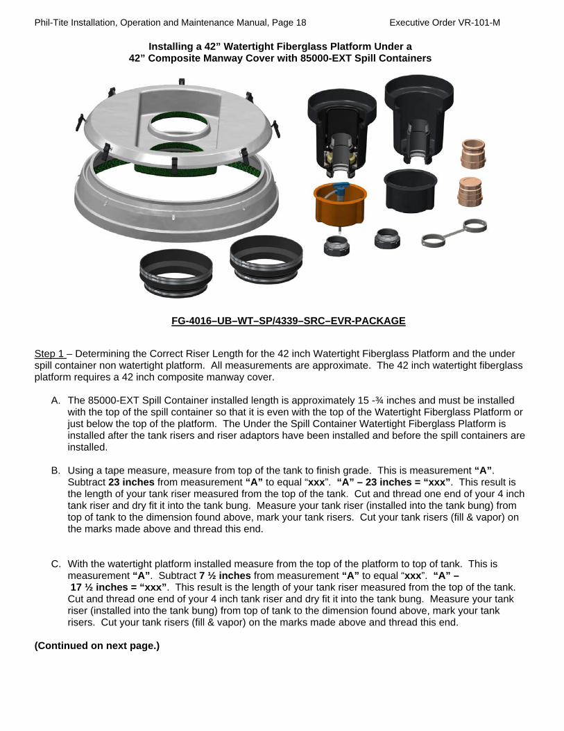
Phil-Tite Installation, Operation and Maintenance Manual, Page 18 Executive Order VR-101-M
Installing a 42” Watertight Fiberglass Platform Under a 42” Composite Manway Cover with 85000-EXT Spill Containers
FG-4016–UB–WT–SP/4339–SRC–EVR-PACKAGE
Step 1 – Determining the Correct Riser Length for the 42 inch Watertight Fiberglass Platform and the under spill container non watertight platform. All measurements are approximate. The 42 inch watertight fiberglass platform requires a 42 inch composite manway cover.
A. The 85000-EXT Spill Container installed length is approximately 15 -¾ inches and must be installed
with the top of the spill container so that it is even with the top of the Watertight Fiberglass Platform or just below the top of the platform. The Under the Spill Container Watertight Fiberglass Platform is installed after the tank risers and riser adaptors have been installed and before the spill containers are installed.
B. Using a tape measure, measure from top of the tank to finish grade. This is measurement “A”.
Subtract 23 inches from measurement “A” to equal “xxx”. “A” – 23 inches = “xxx”. This result is the length of your tank riser measured from the top of the tank. Cut and thread one end of your 4 inch tank riser and dry fit it into the tank bung. Measure your tank riser (installed into the tank bung) from top of tank to the dimension found above, mark your tank risers. Cut your tank risers (fill & vapor) on the marks made above and thread this end.
C. With the watertight platform installed measure from the top of the platform to top of tank. This is measurement “A”. Subtract 7 ½ inches from measurement “A” to equal “xxx”. “A” – 17 ½ inches = “xxx”. This result is the length of your tank riser measured from the top of the tank. Cut and thread one end of your 4 inch tank riser and dry fit it into the tank bung. Measure your tank riser (installed into the tank bung) from top of tank to the dimension found above, mark your tank risers. Cut your tank risers (fill & vapor) on the marks made above and thread this end.
(Continued on next page.)

Phil-Tite Installation, Operation and Maintenance Manual, Page 19 Executive Order VR-101-M
Step 2 – Dry Fit All Components
Dry fit your riser to verify your measurements. After you have dry fit all components and are satisfied with your measurements, apply an approved fuel resistant, non hardening thread sealant (pipe dope) to the NPT threads on tank end of the risers.
Step 3 – Install Tank Risers
Install and torque the tank risers into the tank bungs per tank manufacture instructions.
Step 4 – Install the M-1600 Riser Support Bracket before you install the M/F 4X4 Riser Adaptors Install the M-1600 Riser Support bracket between the two 4 inch (Fill and Vapor) tank risers just below the top of the tank riser threads for the M/F 4X4 riser adaptors. Tighten and/or set the turn buckles to maintain the space between the two tank risers at 16 inches on center.
Step 5 – Check your dimensions
With the M/F 4X4 riser adaptors and spill containers dry fitted, check the dimension from the top of the spill container to finish grade. You should have 4- ½ inches to 5 inch clearance. Verify the height of the fiberglass platform. Check for 1 -½ inches of clearance between the top of the platform and the bottom of the composite manway cover.
Step 6 - Install the M/F 4X4 riser adaptors
Using the M/F 4X4 Riser Adaptor Installation Instructions install and torque the M/F 4X4 riser adaptors.
Step 7 – Install the fiberglass platform before installing the 85000-EXT Spill Containers.
The Watertight Fiberglass Platform must be installed and latched down before the 85000-EXT Spill Containers can be installed.
You are now ready to install the 85000-EXT Spill Containers. Refer to the 85000-EXT Series Spill Container Installation Instructions on the following pages.

Phil-Tite Installation, Operation and Maintenance Manual, Page 20 Executive Order VR-101-M
85000-EXT Series Spill Container Installation
Step 1 – Preparing the Black Spill Container for Installation
A. Inspect the black spill container ensuring that the ¼ inch flat seal is in place and properly oriented for sealing onto the flared top of drop tube (Fill) or on the M/F 4X4 Riser Adaptor (vapor). On Fill spill containers ensure the drop tube has the special Phil-Tite seal (85039-DT) installed under the upper drop tube flare and is seated on top of and inside the M/F 4X4 riser adaptor installed on top of the tank riser. If you are using a straight drop tube from a different manufacturer, discard the “O”-Ring that may have been shipped with this drop tube and use the special Phil-Tite seal (85039-DT) that is shipped with each Fill Spill Container.
B. 85000-EXT Fill Spill Containers. Inspect the foam filter located inside the container. The filter should
be lying flat and secured by the stainless steel retainer ring. Move the drain valve handle back and forth making sure that the lower screen assembly rises (compresses) when moved to the open position and extends when closed. The drain valve handle should move freely with no binding and snap into place when moved to the closed position.
C. NOTE: DO NOT USE ANY TYPE OF THREAD SEALING COMPOUND (Pipe Dope) FOR SPILL
CONTAINER INSTALLATION! Apply an even coat of Silicon based Spray or Lubrisilk Marine Boron CLS Bond Spray to the black spill container female threads and to the M/F 4X4 riser adaptor male threads or apply a light coating of anti-seize compound. This will reduce the friction between these threads during installation and aid in removal of the spill container at a later date.
Step 2 - Install the Black Spill Container onto the M/F 4X4 Riser Adaptor
By hand, thread the black spill container onto the male threads of the M/F 4X4 riser adapter, taking care not to cross thread the spill container riser threads. These threads are straight threads, not NPT pipe threads. The spill container must screw down and seat on the top of the drop tube flare (Fill) or on the top of the M/F 4X4 riser adaptor sealing surface (Vapor).
Step 3 – Tightening the Spill Containers
Using a ½ inch drive torque wrench and the special tool adapter (T-7101 or T-7002A, Black) from Phil-Tite Tool Kit (T-7043), tighten the Spill Container onto the M/F 4X4 Riser Adaptor threads to a torque value between 75 and 100 ft. lbs.
Step 4 – Final Installation Check
Watertight Platform - ensure that the top of the spill containers are even with or just below the top of the platform and the watertight boots are installed (small end around the platform openings, large end around the spill container(s). Check to insure that the watertight latches are closed.
Step 5 – Drain Valve Testing
Test the drain valve assembly as described in ARB test procedure TP-201.1D. The spill container is now ready for the installation of the rotatable (swivel) adaptor and dust cap. Install the fill and/or vapor swivel adaptor using the SWF-100 series/SWV-101 series Installation Instructions. Torque the swivel adaptor to a value between 50 and 75 ft. lbs.

Phil-Tite Installation, Operation and Maintenance Manual, Page 21 Executive Order VR-101-M
Figure B-7 85400 Drain Valve

Phil-Tite Installation, Operation and Maintenance Manual, Page 22 Executive Order VR-101-M
Example of Warranty cards for Phil-Tite 85000 and 85000-1 series Spill Containers

Phil-Tite Installation, Operation and Maintenance Manual, Page 23 Executive Order VR-101-M
Figure B-8 Phil-Tite 85011 Spill Container Lid with Wiper Seal
(Installation and Maintenance are on the following page.)

Phil-Tite Installation, Operation and Maintenance Manual, Page 24 Executive Order VR-101-M
Figure B-8a Installation and Maintenance of 85011

Phil-Tite Installation, Operation and Maintenance Manual, Page 25 Executive Order VR-101-M
Figure B-9 Phil-Tite Debris Containers
Part Number PP 1005 TB (Product) (optional) Part Number PP 1005 TBP (Vapor) (optional) Phil-Tite Hand Pump EP-400-VB (optional)
(For use with vapor debris bucket only)

Phil-Tite Installation, Operation and Maintenance Manual, Page 26 Executive Order VR-101-M
Figure C-1 Phil-Tite SWF-100- series Rotatable Product Adaptor and
Phil-Tite SWV-101- series Rotatable Vapor Adaptor
Franklin Fueling Systems - Phil-Tite SWF-100-B/SWF-100-SS (Fill) & SWV-101-B/SWV-101-SS (Vapor) Swivel Adaptors
Installation Instructions
Swivel Adaptors are designed to be rotatable by hand from the factory and easy to install or remove. They are vapor tight and liquid tight. INSTALLATION: 1. Remove the swivel adaptor from the box, remove foam inserts and inspect for shipping damage. Ensure
that the flat seal is in place and free from damage or defects. Ensure that the vapor poppet opens and closes freely by actuating the poppet by hand. The poppet valve is designed so you can not cock it under the vapor top.
2. IMPORTANT: Do Not Use Any Type of Thread Sealant (Pipe Dope) For Installation. Phil-Tite adaptors are designed to create an optimum, vapor and liquid leak free seal when properly tightened. Apply an even coating of silicon based spray or a light coating of anti-seize compound to the male threads of the spill container riser and/or the swivel adaptor female threads. This will reduce the friction between these threads during installation and aid in removal of the swivel adaptor at a later date.
3. By hand, thread the swivel adaptor onto the spill container riser, taking care not to cross thread. Turn the swivel adaptor until the ¼” flat seal makes contact with the spill container riser.
4. Using a ½ inch drive torque wrench and the special tool adaptor (T-7102, orange) from Phil-Tite Tool Kit (T-7043), tighten the adaptor to a torque value between 50 and 75 ft. lbs.
5. Once properly tightened, install a compatible EVR dust cap listed in EO VR-101. 6. Final Check - Check the operation of the swivel adaptors.
Phil-Tite’s Fill and Vapor swivel adaptors are ARB Phase I EVR certified, as well as tested at the factory and set for a static torque of 40 inch-pounds. Using your hand, turn the top portion of the swivel adaptor; it will rotate 360 degrees by hand. The amount of torque required to turn the swivel by hand is less than the maximum allowed static torque of 108 inch pounds. Phil-Tite’s Fill and Vapor swivel adaptors are warranted against defective materials and workmanship for 1 (one) year of installation or 18 months from date of shipment, with the exception of the poppet ‘O’ Rings and physical damage or abuse to the adaptors. Failure to follow the above instructions can void this warranty. Version 3 June 7, 2004
Product Vapor

Phil-Tite Installation, Operation and Maintenance Manual, Page 27 Executive Order VR-101-M
Figure C-2 Franklin Fueling Systems - Phil-Tite
SWF-100- series & SWV-101- series Swivel Adaptors Maintenance Instructions
The swivel tops should rotate 360 degrees by hand. If you can rotate the swivel tops by hand you are applying less than the maximum torque allowed of 108 in. lbs. of static torque. The Phil-Tite rotatable adaptors are not field serviceable, with the exception of the vapor swivel poppet ‘O’-Ring found on the Vapor swivel adaptor (SWV-101-B and SWV-101-SS). If a leak is found in the vapor top poppet, inspect the brass vapor top for out of round condition. Check the poppet ‘O’-Ring seal for sand, dirt, dust, grit and abrasions between the poppet ‘O’-Ring and the brass sealing surface. These conditions are not covered by the warranty. To check and/or replace the vapor swivel poppet ‘O’-Ring: 1. Remove the vapor swivel adaptor (SWV-101-B or SWV-101-SS) from the black spill container riser using
the special tool adaptor (T-7102, orange) from the Phil-Tite Tool Kit (T-7043).
2. Using a small blade common screwdriver remove the ¼ inch flat seal gasket from the bottom of the vapor adaptor.
3. Push down on the brass spider a ½ inch or so, using a small blade common screwdriver, remove the retainer ring. (Warning: The spider and spring assembly are spring loaded.) This will release the spider assembly, spring, and poppet assembly. By hand, carefully remove these parts.
4. With the vapor poppet assembly removed, inspect the poppet and poppet ‘O’-Ring for cuts, tears or damage. Replace the ‘O’-Ring if necessary. Before re-assembly, spray a small amount of Silicon Spray on the poppet ‘O’- Ring. NOTE: DO NOT USE ANY TYPE OF OIL OR GREASE.
5. Re-assemble the vapor poppet, spring and brass spider in the reverse order from which they were removed.
6. Install the retainer ring and actuate the poppet by hand, making sure the assembly is secure and actuates properly.
7. Using a very small screwdriver, Install a new ¼ inch flat seal. Make sure the ¼ inch flat seal is seated against the sealing surface below the swivel adaptor threads.
8. Reinstall the SWV-101-B or SWV-101-SS vapor swivel on the black spill container riser as described in the “Installation Instructions” and properly torque the swivel adaptor on the spill containment container riser between 50 and 75 ft. lbs.
Important: Apply an even coating of silicon based spray or a light coating of anti-seize compound to the male threads of the spill container riser and/or the swivel adaptor female threads. This will reduce the friction between these threads during installation and aid in removal of the swivel adaptor at a later date.

Phil-Tite Installation, Operation and Maintenance Manual, Page 28 Executive Order VR-101-M
Example of Warranty cards for Phil-Tite Rotatable Adaptors

Phil-Tite Installation, Operation and Maintenance Manual, Page 29 Executive Order VR-101-M
Figure D-1 Franklin Fueling Systems - Phil-Tite
M/F 4x4 Riser Adaptor Installation Instructions
Patent No. 6,840,549 B1
Introduction
M/F 4X4 Riser Adaptors are CNC machined from Grade 1026, Round Carbon Steel Tubing, 5 ½ X ¾ inch. The female threads are NPT and a cavity is machined above these threads to provide additional room for those tank risers whose threads are tapered more than ASTM standards or the end is not cut square. The male threads are straight machine threads with the top providing a machined surface on which a gasket can seal and ensures that the seal is not compromised by improperly cut or improperly finished tank risers. This riser adaptor is to be installed on product and vapor spill containers and tank gauging risers. As an option, this riser adaptor can be installed on other connections.
1. When installing Spill Containers - When you will be installing a spill container onto the M/F 4X4 riser adaptor it is important to cut and thread the tank riser to the correct height. See the figures below or the spill container installation instructions for tank riser measurements.
2. Dry fit all components to ensure correct measurements and height adjustments before final assembly. See the two following diagrams or the spill container instructions.
3. All Other Tank Risers - For tank riser, other than spill container risers determine your required riser height, and then subtract 1 ¾ inches from your tank riser to allow for the M/F 4X4 riser adaptor.
4. Pre-Assemble – Dry fit ALL components to ensure correct measurements and height adjustments before final assembly.
5. All Tank Risers - After you have dry fit all components and are satisfied with your measurements, apply an approved fuel resistant, non hardening thread sealant (pipe dope) to the NPT threads on the male threads of the tank riser.
By hand, thread the M/F 4X4 riser adaptors onto the steel tank riser pipes. Using the approved installation tool adaptor (T-7102, Orange) and Tee handle from the Phil-Tite T-7043 Tool Kit with the appropriate ½ inch drive torque wrench; tighten the M/F 4X4 riser adaptors female NPT threads to a torque value of 175 to 200 foot-pounds. July 2005

Phil-Tite Installation, Operation and Maintenance Manual, Page 30 Executive Order VR-101-M
Figure D-2 Diagram of M/F 4x4 for use with 85000 Series Spill Container

Phil-Tite Installation, Operation and Maintenance Manual, Page 31 Executive Order VR-101-M
Figure D-3 Diagram of M/F 4x4 for use with 85000-1 Series Spill Container

Phil-Tite Installation, Operation and Maintenance Manual, Page 32 Executive Order VR-101-M
Figure E-1 Morrison Brothers Adaptor Dust Caps
323C-0100ACEVR (vapor adaptor dust cap) 305C-0100ACEVR (product adaptor dust cap)
TO BE FILLED OUT BY INSTALLER/MAINTENANCE PERSON
Name of Maintenance Service Company: _____________________________________________________ Address: _____________________________________________________ _____________________________________________________ Date of Install: ________________________________________ Name and Location of Install: _____________________________________________________
Morrison Bros. Co. 24th & Elm St. Dubuque, IA 52001
WARRANTY CARD All Morrison products are thoroughly tested before shipment and only material found to be defective in manufacture will be replaced. Claims must be made within one year from the date of installation, and Morrison Bros. Co. will not allow claims for labor or consequential damage resulting from purchase, installation, or misapplication of the product. Expiration Date:

Phil-Tite Installation, Operation and Maintenance Manual, Page 33 Executive Order VR-101-M
Figure E-2 OPW 634TT-EVR and 1711T-EVR Dust Caps
Operation and Maintenance: Annually inspect seal for nicks, tears or deformations. If required replace with OPW P/N: H15005M for 634TT and H10886M for 1711T.
Standard Product Warranty OPW warrants that products sold by it are free from defects in materials and workmanship for a period of one year from the date of manufacture by OPW (ECO products two years from date of manufacture.) Proof of purchase may be required. As the exclusive remedy under this limited warranty, OPW, will at its sole discretion, repair, replace, or issue credit for future orders for any product that may prove defective within the one year date of manufacture period (repairs, replacements, or credits may be subject to prorated warranty for remainder of the original warranty period, complete proper warranty claim documentation required.) This warranty shall not apply to any product that has been altered in any way, which has been repaired by any party other than a service representative authorized by OPW, or when failure is due to misuse, or improper installation or maintenance. OPW shall have no liability whatsoever for special, incidental or consequential damages to any party, and shall have no liability for the cost of labor, freight, excavation, clean up, downtime, removal, reinstallation, loss of profit, or any other cost or charges. For any product certified to California 2001 standards, OPW warrants that product sold by it are free from defects in material and workmanship for a period of one year from date of manufacture or one year from date of registration of installation not to exceed 15 months from date of manufacture by OPW. THIS WARRANTY IS IN LIEU OF ALL OTHER WARRANTIES, EXPRESS OR IMPLIED, AND SPECIFICALLY THE WARRANTIES OF MERCHANTABILITY AND FITNESS FOR A PARTICULAR PURPOSE. THERE ARE NO WARRANTIES, WHICH EXTEND BEYOND THE DESCRIPTION ON THE FACE HEREOF.
P.O. Box 405003 * Cincinnati, Ohio 45240-5003 1-800-422-2525 Domestically 513-870-3315 Internationally
www.opw-fc.com

Phil-Tite Installation, Operation and Maintenance Manual, Page 34 Executive Order VR-101-M
Figure E-3
EBW 304-301 (vapor) and EBW 777-201 (product) Dust Caps
EBW 304-301-01 or 02 Vapor (Gas) EBW 777-201-01 Product (Gas) EBW 304-301-03 or 04 Vapor (Gas/E85) EBW 777-201-02 Product (Gas/E85)
Visually inspect the seal in cap and replace if damaged or missing. Use replacement parts: Vapor and Product Caps (Gas): (777-111-01) Vapor and Product Caps (Gas/E85): (950-215-01)

Phil-Tite Installation, Operation and Maintenance Manual, Page 35 Executive Order VR-101-M
Figure E-4 OPW 634LPC (product) and 1711LPC (vapor) Dust Caps
Operation and Maintenance: Annually inspect seal for nicks, tears or deformations. If required replace with OPW P/N: H15005M.
Standard Product Warranty OPW warrants that products sold by it are free from defects in materials and workmanship for a period of one year from the date of manufacture by OPW (ECO products two years from date of manufacture.) Proof of purchase may be required. As the exclusive remedy under this limited warranty, OPW, will at its sole discretion, repair, replace, or issue credit for future orders for any product that may prove defective within the one year date of manufacture period (repairs, replacements, or credits may be subject to prorated warranty for remainder of the original warranty period, complete proper warranty claim documentation required.) This warranty shall not apply to any product that has been altered in any way, which has been repaired by any party other than a service representative authorized by OPW, or when failure is due to misuse, or improper installation or maintenance. OPW shall have no liability whatsoever for special, incidental or consequential damages to any party, and shall have no liability for the cost of labor, freight, excavation, clean up, downtime, removal, reinstallation, loss of profit, or any other cost or charges. For any product certified to California 2001 standards, OPW warrants that product sold by it are free from defects in material and workmanship for a period of one year from date of manufacture or one year from date of registration of installation not to exceed 15 months from date of manufacture by OPW. THIS WARRANTY IS IN LIEU OF ALL OTHER WARRANTIES, EXPRESS OR IMPLIED, AND SPECIFICALLY THE WARRANTIES OF MERCHANTABILITY AND FITNESS FOR A PARTICULAR PURPOSE. THERE ARE NO WARRANTIES, WHICH EXTEND BEYOND THE DESCRIPTION ON THE FACE HEREOF.
P.O. Box 405003 * Cincinnati, Ohio 45240-5003 1-800-422-2525 Domestically 513-870-3315 Internationally
www.opw-fc.com

Phil-Tite Installation, Operation and Maintenance Manual, Page 36 Executive Order VR-101-M
Figure E-5 CompX Security Products (CSP)
CSP1-634LPC (product), CSP2-634LPC (product), CSP3-1711LPC (vapor) and CSP4-1711LPC (vapor)
Tank Commander Dust Caps
Figure F-1

Phil-Tite Installation, Operation and Maintenance Manual, Page 37 Executive Order VR-101-M
Franklin Fueling Systems (FFS) PV-Zero Pressure/Vacuum Vent Valve

Phil-Tite Installation, Operation and Maintenance Manual, Page 38 Executive Order VR-101-M

Phil-Tite Installation, Operation and Maintenance Manual, Page 39 Executive Order VR-101-M

Phil-Tite Installation, Operation and Maintenance Manual, Page 40 Executive Order VR-101-M

Phil-Tite Installation, Operation and Maintenance Manual, Page 41 Executive Order VR-101-M

Phil-Tite Installation, Operation and Maintenance Manual, Page 42 Executive Order VR-101-M

Phil-Tite Installation, Operation and Maintenance Manual, Page 43 Executive Order VR-101-M

Phil-Tite Installation, Operation and Maintenance Manual, Page 44 Executive Order VR-101-M

Phil-Tite Installation, Operation and Maintenance Manual, Page 45 Executive Order VR-101-M

Phil-Tite Installation, Operation and Maintenance Manual, Page 46 Executive Order VR-101-M

Phil-Tite Installation, Operation and Maintenance Manual, Page 47 Executive Order VR-101-M

Phil-Tite Installation, Operation and Maintenance Manual, Page 48 Executive Order VR-101-M

Phil-Tite Installation, Operation and Maintenance Manual, Page 49 Executive Order VR-101-M
Figure F-2 Husky Model 5885 Pressure/Vacuum Vent Valve

Phil-Tite Installation, Operation and Maintenance Manual, Page 50 Executive Order VR-101-M

Phil-Tite Installation, Operation and Maintenance Manual, Page 51 Executive Order VR-101-M

Phil-Tite Installation, Operation and Maintenance Manual, Page 52 Executive Order VR-101-M
Figure G-1 Ever-Tite Tank Gauge Port Components
Ever-Tite #4097AGBR Adaptor with Hex Base
Installation Instructions 1. Thread by hand to avoid cross threading. 2. Tighten adaptor to 75 to 100 foot-pounds torque.
Warranty The Company warrants its goods to be free from defects in material and workmanship as represented in our catalogs or applicable drawings and specifications agreed to by us at the time of acceptance of the order by Ever-Tite Coupling Products. Our obligation under this warranty shall be limited to repairing or replenishing any parts which shall, within one (1) year after shipment to the original purchaser, be demonstrated to be defective. This warranty is expressly in lieu of all other warranties, express or implied, including the warranties of merchantability and fitness. No person, firm or corporation is authorized to assume for us any other liability in connection with the sale of these goods.
Ever-Tite #4097MBR Cap Ever-Tite
#4097AGMBRNL Adaptor

Phil-Tite Installation, Operation and Maintenance Manual, Page 53 Executive Order VR-101-M
Figure G-2 Veeder-Root P/N 312020-952 Tank Gauge Port Cap and Adaptor
Installation Instructions Install an ARB approved machined adaptor onto the riser. Apply a gasoline-resistant, non-hardening thread sealant to the threads of the riser adaptor only. Next screw the ring from the Veeder-Toot kit (P/N 312020-952) onto the riser adaptor by hand until the gasket contacts the sealing surface. Then use a torque wrench attached to an appropriate strap wrench (K-D Specialty tools nylon strap oil filter wrench P/N 3149, or equivalent) and tighten the ring to 35-45 ft.-lbs. Loosen the cord grip nut and push the cable through the cap and cord grip, then clamp the cap onto the ring. Warranty We warrant that this product will be free from defects in materials and workmanship for a period of 1 year from the date of installation or 24 months from the date of Invoice, whichever occurs first. During the warranty period, we or our representative will repair or replace the product. If determined by us to be defective, at the location where the product is in-use and at no charge to the purchaser. We shall not be responsible for any expenses incurred by the user. This warranty applies only when the product is installed in accordance with Veeder-Root’s specifications and a Warranty Registration and Checkout Form has been filed with Veeder-Root by an Authorized Veeder-Root Distributor. This warranty will not apply to any product which has been subjected to misuse, negligence or accident; or misapplied; or used in violation of product manuals, instructions or warnings; or modified or repaired by unauthorized persons or improperly installed.
Original Identification Method New Identification Method
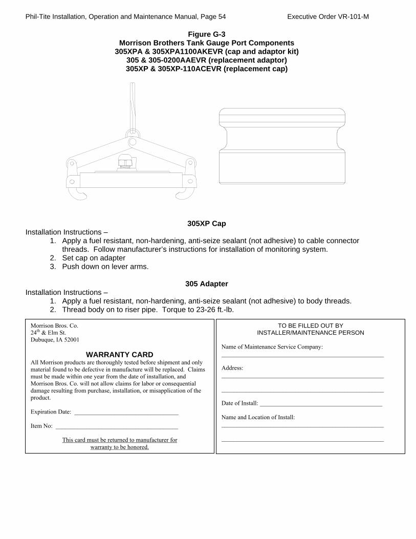
Phil-Tite Installation, Operation and Maintenance Manual, Page 54 Executive Order VR-101-M
Figure G-3 Morrison Brothers Tank Gauge Port Components
305XPA & 305XPA1100AKEVR (cap and adaptor kit) 305 & 305-0200AAEVR (replacement adaptor) 305XP & 305XP-110ACEVR (replacement cap)
305XP Cap Installation Instructions –
1. Apply a fuel resistant, non-hardening, anti-seize sealant (not adhesive) to cable connector threads. Follow manufacturer’s instructions for installation of monitoring system.
2. Set cap on adapter 3. Push down on lever arms.
305 Adapter
Installation Instructions – 1. Apply a fuel resistant, non-hardening, anti-seize sealant (not adhesive) to body threads. 2. Thread body on to riser pipe. Torque to 23-26 ft.-lb.
Morrison Bros. Co. 24th & Elm St. Dubuque, IA 52001
WARRANTY CARD All Morrison products are thoroughly tested before shipment and only material found to be defective in manufacture will be replaced. Claims must be made within one year from the date of installation, and Morrison Bros. Co. will not allow claims for labor or consequential damage resulting from purchase, installation, or misapplication of the product. Expiration Date: __________________________________ Item No: ________________________________________
This card must be returned to manufacturer for warranty to be honored.
TO BE FILLED OUT BY INSTALLER/MAINTENANCE PERSON
Name of Maintenance Service Company: _____________________________________________________ Address: _____________________________________________________ _____________________________________________________ Date of Install: ________________________________________ Name and Location of Install: _____________________________________________________ _____________________________________________________

Phil-Tite Installation, Operation and Maintenance Manual, Page 55 Executive Order VR-101-M
Figure G-4 EBW Tank Gauge Components
EBW 90037 and 90037-E (cap and adaptor)
Annual maintenance of the probe riser cap assemblies is normally not required. Whenever probe service is necessary, inspect service cap seal for damage and replace, if necessary, at that time.

Phil-Tite Installation, Operation and Maintenance Manual, Page 56 Executive Order VR-101-M
FIGURE H-1 Phil-Tite Phase I EVR
OPW 61-T Straight Drop Tube
Installation Instructions 1. Cut the tube to a length so that it is not more than 6 inches from the bottom of the tank. Saw off the excess tube at a 45-degree angle, or per local codes or requirements, and file off any sharp burrs. Operation and Maintenance: Annually: Test the drop tube seal with ARB procedure TP-201.1C or TP-201.1D. If the drop tube seal passes testing, no further maintenance is required. If the drop tube seal fails testing, replace the drop tube seal with Phil-Tite Drop Tube Seal (P/N 85039-DT) for 4 inch tubes. Re-test the drop tube seal with ARB procedure TP-201.1C or TP-201.1D. Standard Product Warranty OPW warrants that products sold by it are free from defects in materials and workmanship for a period of one year from the date of manufacture by OPW (ECO products two years from date of manufacture.) Proof of purchase may be required. As the exclusive remedy under this limited warranty, OPW, will at its sole discretion, repair, replace, or issue credit for future orders for any product that may prove defective within the one year date of manufacture period (repairs, replacements, or credits may be subject to prorated warranty for remainder of the original warranty period, complete proper warranty claim documentation required.) This warranty shall not apply to any product that has been altered in any way, which has been repaired by any party other than a service representative authorized by OPW, or when failure is due to misuse, or improper installation or maintenance. OPW shall have no liability whatsoever for special, incidental or consequential damages to any party, and shall have no liability for the cost of labor, freight, excavation, clean up, downtime, removal, reinstallation, loss of profit, or any other cost or charges. For any product certified to California 2001 standards, OPW warrants that product sold by it are free from defects in material and workmanship for a period of one year from date of manufacture or one year from date of registration of installation not to exceed 15 months from date of manufacture by OPW. THIS WARRANTY IS IN LIEU OF ALL OTHER WARRANTIES, EXPRESS OR IMPLIED, AND SPECIFICALLY THE WARRANTIES OF MERCHANTABILITY AND FITNESS FOR A PARTICULAR PURPOSE. THERE ARE NO WARRANTIES, WHICH EXTEND BEYOND THE DESCRIPTION ON THE FACE HEREOF.
YOU MUST USE THE PHIL-TITE DROP TUBE SEAL (P/N 85039-DT). DO NOT USE THE ROUND O-RING PROVIDED BY OPW.

Phil-Tite Installation, Operation and Maintenance Manual, Page 57 Executive Order VR-101-M
Figure H-2
EBW 782 Straight Drop Tube
Installation Instructions
1. Cut the tube to a length so that it is not more than 6 inches from the bottom of the tank. Saw off the excess tube at a 45-degree angle, or per local codes or requirements, and file off any sharp burrs. Operation and Maintenance: Annually: Test the drop tube seal with ARB procedure TP-201.1C or TP-201.1D. If the drop tube seal passes testing, no further maintenance is required. If the drop tube seal fails testing, replace the drop tube seal with Phil-Tite Drop Tube Seal (P/N 85039-DT) for 4 inch tubes. Re-test the drop tube seal with ARB procedure TP-201.1C or TP-201.1D.
YOU MUST USE THE PHIL-TITE DROP TUBE SEAL (P/N 85039-DT).
Phil-Tite Installation, Operation and Maintenance Manual, Page 58 Executive Order VR-101-M
Figure J-1 Phil-Tite 61SO-PT-Drop Tube with Mechanical Overfill Prevention Valve
FRANKLIN FUELING SYSTEM - PHIL-TITE
August 2006
FOR
PHIL-TITE 61SO - PT - DROP TUBE with MECHANICAL
OVERFILL PREVENTION VALVE
IMPORTANT: Please read these assembly and installation instructions completely and carefully before starting.
THESE INSTRUCTIONS ARE VERY DIFFERENT FROM OTHER
MANUFACTURERS INSTRUCTIONS AND REQUIRE THE UPPER DROP TUBE
SECTION TO BE FLARED USING FLARING TOOL T-6100-FT
Installation, Operation & Maintenance

Phil-Tite Installation, Operation and Maintenance Manual, Page 59 Executive Order VR-101-M
GENERAL INSTRUCTIONS The Phil-Tite 61SO-PT Overfill Prevention Valve and drop tube is designed for tight fill connections, gravity drop applications only, and to provide positive shut-off of product delivery before an overfill condition occurs without intervention from the transport driver (per EPA and State requirements). The valve features a sealed float pivot and a threaded lower tube connection with a maximum vapor leak rate of 0.17CFH @ 2” H20 or less in accordance with ARB TP-201.1C or D. The 61SO-PT Overfill Prevention Valve and Drop Tube is installed below the spill container in the UST in place of a standard straight drop tube. During a delivery the main 61SO-PT valve closes when the liquid level is at 95% from the top of the tank. A small bypass valve remains open to allow the delivery hose to drain at 3-5 gallons per minute. If the delivery truck valve is not closed after initial shut-off (95%), and the liquid level reaches 98% the bypass valve will close and will restrict all fuel deliveries. The 61SO-PT models are designed to be installed with a PHIL-TITE Spill Container, and M/F 4 X 4 riser adaptor using Phil-Tite installation instructions, work sheet, torque adapters and Flaring Tool (T-6100-FT). IMPORTANT Read these assembly and installation instructions completely and carefully prior to starting. Check to make sure you have the special seal (85039-DT) and a package of JB KWIK. Do not use any substitutes for these items. The use of substitute parts may cause product failure. Failure to follow these instructions may cause improper product operation or premature failures which may permit storage tank overfill. An overfilled storage tank may create hazardous conditions and/or environmental contamination. CAUTION Do not remove elastic band from around the float until instructed to do so. Damage to the valve assembly may result. WARNINGS Failure to properly connect delivery hose and elbow, and/or disconnecting a liquid filled delivery
hose or elbow will result in a hazardous spill, which may result in personal injury, property damage, fire, explosion, and water and soil pollution. Make sure all connections, including the hose
and elbow connections between the storage tank and transport are securely coupled.
Make sure the lip seal and/or all gaskets in the delivery elbows and adaptors are properly in place to prevent spills.
Do not make a delivery using damaged or missing parts, which prevent tight connections.
Normal Operation of the over-fill valve: A Hose ”Kick” and reduced flow signal that the tank has reached 95% full. Fuel flow is reduced to 5gpm through a bypass valve. Close the transport delivery valve(s) and drain hose into tank before disconnecting any hose fitting. If delivery is not stopped and the liquid rises above 98% of tank capacity the bypass valve will close completely shutting off all flow into the UST. Overfilled Tank: The inability to drain the hose or failure of the hose to drain after closing the delivery valve(s) signals an overfilled tank. Do Not Disconnect any delivery hose fittings until the liquid level in the tank has been lowered to allow the hose to drain into the tank. Attention: In the event you are splashed with fuel, remove all wetted clothing immediately. Do not go into an enclosed area and stay away from any and all ignition sources. IMPORTANT Determine if the underground storage tank is equipped with a ball float vent valve. In all systems, the shut-off point of the 61SO - PT must be reached before the ball float reduces flow to ensure proper overfill valve operation. See State Water Resources Control Board Local Guidance Letter LG-150-1 at www.waterboards.ca.gov/ust/leak_prevention/lgs/index.html or call (916) 341-5752 or (916) 341-5782.
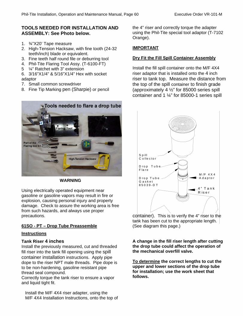
Phil-Tite Installation, Operation and Maintenance Manual, Page 60 Executive Order VR-101-M
S p i l lC o l le c t o r
D r o p T u b eF la r e
D r o p T u b eG a s k e t8 5 0 3 9 - D T
M /F 4 X 4A d a p t o r
4 ” T a n kR is e r
TOOLS NEEDED FOR INSTALLATION AND ASSEMBLY: See Photo below. 1. ¾”X20’ Tape measure 2. High-Tension Hacksaw, with fine tooth (24-32
teeth/inch) blade or equivalent. 3. Fine teeth half round file or deburring tool 4. Phil-Tite Flaring Tool Assy. (T-6100-FT) 5 ¼” Ratchet with 3” extension 6. 3/16”X1/4” & 5/16”X1/4” Hex with socket adaptor 7. Small common screwdriver 8. Fine Tip Marking pen (Sharpie) or pencil
WARNING Using electrically operated equipment near gasoline or gasoline vapors may result in fire or explosion, causing personal injury and property damage. Check to assure the working area is free from such hazards, and always use proper precautions. 61SO - PT – Drop Tube Preassemble
Instructions
Tank Riser 4 inches Install the previously measured, cut and threaded fill riser into the tank fill opening using the spill container installation instructions. Apply pipe dope to the riser NPT male threads. Pipe dope is to be non-hardening, gasoline resistant pipe thread seal compound. Correctly torque the tank riser to ensure a vapor and liquid tight fit.
Install the M/F 4X4 riser adapter, using the M/F 4X4 Installation Instructions, onto the top of
the 4” riser and correctly torque the adapter using the Phil-Tite special tool adaptor (T-7102 Orange). IMPORTANT Dry Fit the Fill Spill Container Assembly Install the fill spill container onto the M/F 4X4 riser adaptor that is installed onto the 4 inch riser to tank top. Measure the distance from the top of the spill container to finish grade (approximately 4 ½” for 85000 series spill container and 1 ¼” for 85000-1 series spill
container). This is to verify the 4” riser to the tank has been cut to the appropriate length. (See diagram this page.)
A change in the fill riser length after cutting the drop tube could affect the operation of the mechanical overfill valve.
To determine the correct lengths to cut the upper and lower sections of the drop tube for installation; use the work sheet that follows.

Phil-Tite Installation, Operation and Maintenance Manual, Page 61 Executive Order VR-101-M
FRANKLIN FUELING SYSTEMS - PHIL-TITE Figure J-1a
Measurement Work Sheet to Determine the Drop Tube Lengths for 61SO–PT–(X) Mechanical Overfill Prevention Valve and Drop Tube
Date: _____________
Site Location: (name) ________ ___ ______
Installing Contractor: (name) ___ ___________________ _
Address ________________________________ Address __________________________________
City/State _______________________________City/State__________________________________
Contact/Phone __________________________Contact/Phone ______________________________
Tank Number: _________ Product: ________ Tank Type: ______________ ______ __
Tank Manufacture: Tank Capacity _____ _________ (From Mfg. tank chart) Tank Diameter (from Mfg. tank chart) ___________________inches STEP 1 Determine the distance in inches the 61SO-PT- XX mechanical overfill valve must be set below the top of the tank for it to close when the tank reaches 95% capacity. Using the manufactures tank chart, find the tank total capacity in gallons. Multiply this number by 95%. If you want the shutoff valve to close at less than 95%, (i.e. then use that percentage to multiply by the total tank capacity in gallons.
Total tank capacity in gallons ( ) X (0.95) = ____________________________ gallons
Using the manufacturer tank chart, convert the 95% capacity in gallons to inches =___________inches
Use TABLE 1 to calculate the correct distance.
TABLE 1 Primary Tank Diameter in (inches) …………………………………… ( )
Subtract the 95% Liquid level converted to inches …….…….... -- ( )
This results is the distance in inches below the top of the tank to the tank’s 95% liquid level in inches ……………………......… = ( )
Subtract 2” inches (from the above figure) ……………………......... --- 2.00
This is “the distance” that the 61SO-PT overfill valve must be set below the top of the tank for the overfill valve to operate correctly when the tank reaches 95% capacity: ........... = ( ) * * Transfer this number to Step 3 and Table 2 for determining the UPPER DROP TUBE LENGTH. (Continued on next page.)

Phil-Tite Installation, Operation and Maintenance Manual, Page 62 Executive Order VR-101-M
STEP 2 Determine the total height of the Fill (product) riser height with the M/F 4X4 riser adapter installed. See Figure 1, Measurement “A” (Note: Both the fill riser and M/F 4X4 adapter must be installed and correctly torqued.) To determine the fill riser height, (M/F 4X4 riser adapter must be installed) take a tape measure and measure from inside the installed riser, (hook the tape on the end of the riser or on the inside top of tank) and measure from the bottom end of the riser to the top of the M/F 4X4 threaded adapter installed on top of the riser. This is measurement “A” ( ) inches
STEP 2a To determine the total drop tube length, take the tape measure and measure from inside the riser from the bottom of the tank to the top of the M/F 4X4 riser adapter. This is Measurement “B”( ) inches (See Figure 1) ___________________________________________
STEP 3 Determining the Upper Drop Tube Length above the mechanical overfill prevention valve. Use the final results in inches determined in Step 1 ( ) and ADD it to measurement “A” from Step 2 ( ) See Table 2.
TABLE 2
The final results from Step 1 ( )
Measurement “A” Step 2 ADD + ( )
UPPER DROP TUBE LENGTH = ( )
This is the exact length the top section of the aluminum drop tube should be above the mechanical overfill prevention valve for this tank installation. NOTE: If this UST has a manway and the fill riser is installed in the top of the manway you must add the height of the manway to your riser length “A” for the over fill valve to be set the correct distance below the top of the tank. See the Flaring Tool instructions for cutting and flaring the drop tube. Note: To determine if an 8 foot drop tube can be used, take the Upper Drop Tube Length, and ADD 102 inches. If this figure is greater than your Total Drop Tube Length, you can use an 8 foot drop tube assembly. Figure 1
Step 4 Determining the total length of the drop tube. After flaring the upper drop tube section take the results of measurement “B” in Step 2a ( ), and subtract 6 or less inches = ( ). Starting at the flare end (upper section) measure the entire length of the drop tube from the top down to the bottom and mark this measurement near the bottom portion of the drop tube. This will be your cut line for the bottom portion of the drop tube. See Table 3 TABLE 3
Measurement “B” from Step 2a ( )
Less 6” or local regulatory amount -- ( )
TOTAL DROP TUBE LENGTH = ( )
Hint: Use 5 7/8 inches in lieu of 6 inches to ensure you do not exceed 6 inches. To make a perfect straight cut follow the Flaring tool instructions using the flaring tool cutter to make this cut. Place the marked cut line right on the cutting blade and make your cut.

Phil-Tite Installation, Operation and Maintenance Manual, Page 63 Executive Order VR-101-M
STEP 5: MARKING FINAL CUT MARKS
Upper Drop Tube Length
Mark the upper tube length with the dimension found in Step 3 Table 2 from the Drop Tube work sheet. Measure the upper section of the drop tube with a tape measure from where it connects to the mechanical over-fill valve to the dimension from Table 2 “Upper Drop Tube Length”. Mark the drop tube using a black fine point marker (Sharpie) or pencil. This will be the length of the upper drop tube section of the drop tube after flaring. See Step 5 Photos below. Rough Cut Length
Measure 2” to 2 1/2” further up the Upper Drop Tube Length and mark the drop tube using a black fine point marker (Sharpie). This will be your rough cut mark. See Step 5, Photo 2. STEP 5 Photos – Marking the Upper Drop Tube length and the rough cut mark
STEP 6: REMOVE EXCESS UPPER DROP TUBE – Rough Cut Using a Hack Saw or SawsAll, saw through the Upper drop tube on the rough cut mark. This cut does not have to be straight. See Step 6 Photos. CAUTION -DO NOT use a pipe or tubing cutter to cut the upper drop tube, this may damage the tube, causing it to be out of round. STEP 6: Photo – Performing the rough cut.
STEP 7: INSTALL THE DRIVE RING Position the Drive Ring with the alignment markings facing forward on the upper drop tube length mark, marked in Step 5. There should be approximately 1-3 inches of excess upper drop tube beyond the Drive Ring. See next 2 photos.

Phil-Tite Installation, Operation and Maintenance Manual, Page 64 Executive Order VR-101-M
STEP 7 Cont.
STEP 8: TIGHTEN THE DRIVE RING Alternately Tighten the 4 Hex Screws on the Drive Ring Check that the drive ring is still on the mark made for the drop tube Upper Drop Tube Length found in Step 3. See photo below:
STEP 9: POSITION THE DRIVE RING IN THE FLARING TOOL Position the Upper Drop Tube with the Drive Ring into the Flaring Tool. See Photo Below:
STEP 10: SECURING THE DRIVE RING IN THE FLARING TOOL Use the wing nut to tighten the Drive Wheel into the drive ring groove just enough to create a light tension between the drive wheel and drive ring (do not over tighten). See Photo below:
STEP 11: PERFORMING the PRECISION CUT
Apply light hand pressure on the cutter handle and rotate the drop tube to cut the proper dimension. Do not apply excessive pressure. Should the drop tube not turn, tighten the thumb-screw tension until the
handle drives the drive ring. After the drop tube is cut there should be 1/4 of an inch of material remaining. See Photo below. After making the precision cut, remove any burrs on the inside of the drop
tube using a fine tooth file or de-burring tool. You are now ready to start performing the 0-45 degree flare.

Phil-Tite Installation, Operation and Maintenance Manual, Page 65 Executive Order VR-101-M
STEP 12: FIRST FLARING ROLLER POSITION The first position for the flaring roller is in the 0 – 45 degrees position. Use the long hex screw to connect the flaring roller to the flaring tool. See Photos Below for correct position.
STEP 13: PERFORMING O – 45 DEGREE FLARE Turn the long hex screw until it is snug. While turning the Flaring Tool Handle, slowly tighten the long hex screw applying continual pressure until a 45 degree
flare is made. The hex screw will bottom out and become tight. When this happens stop turning the long hex screw, the first half of the flare is complete. Remove the long hex screw and Flaring roller.
STEP 14: 45 – 90 DEGREE FLARING POSITION Install the flaring roller in the 45 – 90 degree position using the short hex screw. See photo below.
STEP 15: PERFORMING - 45 – 90 DEGREE FLARE Turn the short hex screw until it is snug. While turning the Flaring Tool Handle, slowly tighten the short hex screw applying continual pressure until the 90 degree flare is completed. The short hex screw will bottom out and become tight. When this happens, stop turning the short hex screw, the 90 degree flare is complete. Remove the short hex screw and Flaring roller. See photo below.

Phil-Tite Installation, Operation and Maintenance Manual, Page 66 Executive Order VR-101-M
JB Kwik sets in 4 minutes. Allow to cure for a minimum of 4 hours.
Seal for drop tube. Use only one seal.
STEP 16: FLARE COMPLETED After the flaring procedure is completed, there should be smooth, flat 90-degree flare. Remove the flaring roller from the flare tool and the drive ring from the drop tube. See Photo below.
STEP 17: CHECK YOUR FLARE MEASUREMENT Measure the upper drop tube for the correct length. The Upper Drop tube mark should be at the base of the flare. See Photo Below.
STEP 18: INSTALLING THE DROP TUBE SEAL Install the Phil-Tite Special Designed Drop Tube Seal (85039-DT) onto the drop tube with the flat side up against the drop tube flare. See Photo Below.
STEP 19: INSTALLING LOWER DROP TUBE ASSEMBLY
If a vise is used, clamp on the valve body casting only to avoid damage to the float. Mix the two-part JB Kwik provided until the color is uniform. Using a mixing stick, generously apply JB Kwik to the first 6 male threads on the valve body as shown in Figure 2. Make sure coverage is completely around the threads, and work the sealant down into the thread profile. Quickly thread the lower tube onto the valve body. Tighten the tube securely by hand or with a strap wrench. Remove excess sealant and smooth sealant bead with water moistened mixing stick. Important: Allow sealant (JB Kwik) to cure for a minimum of 4 hours before installing the drop tube assembly into a tank with fuel.
Note: After the sealant (JB Kwik) has cured and before installing the drop tube into the tank, a pressure test can be performed on the valve to check for vapor tightness. Seal off both ends of the tube with inflatable plumber’s plugs. Apply a maximum 10" W.C. (1/3 PSI) air pressure. If pressure does not hold and a leak can be located with soap solution, do not install the valve. Send the valve back to Phil-Tite and/or OPW for warranty evaluation.
Caution: Do not over-pressurize. Excess pressure can damage the valve.
Figure 2
Apply Sealant completely around first 6 threads.

Phil-Tite Installation, Operation and Maintenance Manual, Page 67 Executive Order VR-101-M
STEP 20: CUTTING LOWER END OF DROP TUBE Measuring from the underside of the inlet tube flange, mark the overall length of the drop tube a distance of (B) minus 6". Determine dimension (B) from the Drop Tube Measurement Worksheet taken in Step 3, Figure 1 (Top of the PHIL-TITE M/F 4 X 4 Riser Adaptor to the bottom of the tank). Saw/Cut off the excess tube and file off any sharp burrs.
Optional: Install the PHIL-TITE Tank Bottom Protector on the lower tube (Refer to Installation instructions supplied with the Tank Bottom Protector).
STEP 21: PREPARE TANK RISER FOR OVERFILL VALVE INSERTION
IMPORTANT: Inspect the riser pipe for any foreign material. Over spray from tank relining or any internal burrs inside of pipe must be removed prior to installation. Failure to have an unobstructed tank riser pipe may prevent proper installation or operation of the valve. Thoroughly clean top of tank riser pipe.
Important: Before installing the drop tube, allow the sealant to cure for a minimum of 4 hours.
STEP 22: REMOVE ELASTIC BAND
Remove the elastic band securing the float to the valve body. The float will move into an outward position.
STEP 23: INSTALL THE DROP TUBE Make sure the special drop tube seal (85039-DT) is installed correctly. Hold the float down against the valve body and slowly insert the drop tube into the tank riser pipe. Do not force the valve into the tank riser pipe. If any obstruction or foreign matter interferes with smooth insertion of the valve, the tank riser pipe must be cleared. See Figure 3.
WARNING
Failure to follow the assembly and installation instructions or use of excessive force to insert the 61SO - PT will “VOID THE WARRANTY!” STEP 24: CHECK INSTALLATION
Insert the drop tube all the way into the tank until the flange and gasket seat onto the top of the Phil-Tite M/F 4 X 4 Riser Adapter. The float will swing out into the operating position as it passes into the tank. Make sure that the float is aligned along the length of the tank. The length of the tank can easily be determined by locating other manholes or pump boxes that are installed around other tank fittings. Look into the drop tube and align the deflector with the length of the tank. CAUTION: No obstruction in the tank can be within 13 inches from the center of the riser pipe or the valve may not operate properly.
STEP 25: FINAL INSTALLATION
Install a PHIL-TITE Fill Spill Container according to the manufacturer’s installation instructions. Ensure that the drop tube does not rotate while tightening the Spill Container by observing the position of the deflector. Install a PHIL-TITE Rotatable swivel adaptor and tighten according to the manufacturer’s installation instructions. See Figure 4.
Align Float Along Length of Tank Figure 4
Vapor Recovery Riser
Fill Riser
6” Max.
OPW 53V or 30MV Ball Float
13” Min. Clearance for Float
Tube Cut per Local Requirements
The discharge opening of the fill-pipe must be entirely submerged when the liquid level is six inches above the bottom of the tank.

Phil-Tite Installation, Operation and Maintenance Manual, Page 68 Executive Order VR-101-M
Figure 5
STEP 26: INSTALL WARNING PLATE
Slide the tie wrap over the warning plate ears and position warning plate against riser pipe approximately 1 inch below the adaptor. Tighten the tie wrap securely. The valve is now fully installed and in operating position.
STEP 27: VALVE REMOVAL The Over-fill prevention valve can be removed from the tank by removing the Phil-Tite Swivel Adaptor and Spill Container. Reinstall per the above instructions.
Step 28: Electronic Liquid Level Monitoring If an electronic level monitor is installed, it must be calibrated to match the top of the 61SO-PT valve body, correlated to the 95% tank level dimension used during assembly.
PREVENTATIVE MAINTENANCE Annually, inspect the Phil-Tite 61SO-PT by looking down the drop tube opening and ensure that the over-fill valve is open and installed inside. Inspect for any foreign objects inside the drop tube. None are allowed. Check to see if any over-fill conditions have occurred since the last inspection. If an over-fill has occurred did the over-fill valve perform correctly?
CAUTION: Do not insert any foreign object(s) into drop tube if flapper is in the closed position. For example a tank level measuring stick. This will damage the valve and void the Warranty. ALWAYS check the valve position before “sticking” the tank. If valve is in the closed position the tank is either over filled and you need to wait until the liquid level goes down or the 61SO- PT is damaged and needs to be replaced.
Phil-Tite 61SO- PT Performance
Specifications:
This Overfill Prevention Valve was manufactured by OPW and has been tested by OPW to meet the following specifications: “The maximum leak rate does not exceed 0.17 CFH at 2.00 inches W.C. when tested in accordance with ARB TP-201.1C or TP-201.1D. Important: Leave these installation instructions and maintenance procedures with the station operator.

Phil-Tite Installation, Operation and Maintenance Manual, Page 69 Executive Order VR-101-M
Example of Warranty tag for 61SO-PT

Phil-Tite Installation, Operation and Maintenance Manual, Page 70 Executive Order VR-101-M
Figure J-2
EBW Autolimiter II 708-49X series Drop Tube Overfill Prevention Devices
August 2006
FOR
EBW 708-49X- Series Drop Tube with Mechanical
Overfill Prevention Valve (EBW Autolimiter II®) Use on
a Phil-Tite Phase I Vapor Recovery System
IMPORTANT: Please read these assembly and installation
instructions completely and carefully before starting.
THESE INSTRUCTIONS ARE VERY DIFFERENT FROM OTHER
MANUFACTURERS INSTRUCTIONS AND REQUIRE THE UPPER DROP
TUBE SECTION TO BE FLARED USING
PHILTITE FLARING TOOL T-6100-FT
Installation, Operation & Maintenance

Phil-Tite Installation, Operation and Maintenance Manual, Page 71 Executive Order VR-101-M
GENERAL INSTRUCTIONS
The EBW 708-49X- Series Overfill Prevention Valve and drop tube (EBW Autolimiter II®) is designed for tight fill connections, gravity drop applications only, and to provide positive shut-off of product delivery before an overfill condition occurs without intervention from the transport driver (per EPA and State requirements). The valve features a sealed float pivot and a threaded lower tube connection with a maximum vapor leak rate of 0.17CFH @ 2 inches H20 or less in accordance with ARB TP-201.1C or D. For ARB EVR installations the Overfill Prevention Valve and Drop Tube are installed below the spill container drain valve in the underground storage tank (UST) in place of a standard straight drop tube. The EBW Autolimiter II® is designed to be installed in the 4 inch riser pipe of a UST to reduce the flow by 90% (at approximately 92% of tank capacity) and shut the flow off at 95% tank capacity. After the valve has been activated, the delivery hose can be drained. The EBW Autolimiter II® is designed to be installed with a Phil-Tite Spill Container, and M/F 4 X 4 riser adaptor using Phil-Tite installation instructions, work sheets, torque adapters and Flaring Tool (T-6100-FT). IMPORTANT Read these assembly and installation instructions completely and carefully prior to starting. Check to make sure you have the special drop tube seal (85039-DT) and a package of J-B KWIK. Do not use any substitutes for these items. The use of substitute parts may cause product failure. Failure to follow these instructions may cause improper product operation or premature failures which may permit storage tank overfill. An overfilled storage tank may create hazardous conditions and/or environmental contamination. WARNING Failure to properly connect delivery hose and elbow, and/or disconnecting a liquid filled
delivery hose or elbow will result in a hazardous spill, which may result in personal injury, property damage, fire, explosion, and water and soil pollution. Make sure all connections, including the hose
and elbow connections between the storage tank and transport are securely coupled.
Make sure the lip seal and/or all gaskets in the delivery elbows and adaptors are properly in place to prevent spills.
Do not make a delivery using damaged or missing parts which prevent tight connections.
Normal Operation of the over-fill valve: A Hose “Kick” and reduced flow signal that the tank has reached 92% full. Fuel flow is reduced by 90%. Close the transport delivery valve(s) and drain hose into tank before disconnecting any hose fitting. If delivery is not stopped and the liquid rises above 95% of tank capacity the EBW Autolimiter II® valve will shut down the flow into the UST. Overfilled Tank: The inability to drain the hose or failure of the hose to drain after closing the delivery valve(s) signals an overfilled tank. Do Not Disconnect any delivery hose fittings until the liquid level in the tank has been lowered to allow the hose to drain into the tank. Attention: In the event you are splashed with fuel, remove all wetted clothing immediately. Do not go into an enclosed area and stay away from any and all ignition sources. IMPORTANT Determine if the underground storage tank is equipped with a ball float vent valve. In all systems, the shut-off point of the EBW Autolimiter II® must be reached before the ball float reduces flow to ensure proper overfill valve operation. See CA State Water Resources Control Board Local Guidance Letter LG-150-1 at www.waterboards.ca.gov/ust/leak_prevention/lgs/index.html or call (916) 341-5752 or (916) 341-5782.

Phil-Tite Installation, Operation and Maintenance Manual, Page 72 Executive Order VR-101-M
Spill Collector
Drop Tube
Drop Tube Gasket
M/F 4X4 Adaptor
Tank Riser
TOOLS NEEDED FOR INSTALLATION AND ASSEMBLY: See Photo below.
1. ¾ inch X 20 foot Tape measure 2. High-Tension Hacksaw or SawsAll, with
fine tooth (24-32 teeth/inch) blade or equivalent.
3. Fine tooth half round file or de-burring tool 4. Phil-Tite Flaring Tool Assy. (T-6100-FT) 5 ¼ inch Ratchet with 3 inch extension 6. 3/16 inchX1/4 inch & 5/16 inchX1/4 inch
Hex with socket adaptor 7. Small common screwdriver 8. Fine Tip Marking pen (Sharpie) or pencil
WARNING
Using electrically operated equipment near gasoline or gasoline vapors may result in fire or explosion, causing personal injury and property damage. Check to assure the working area is free from such hazards, and always use proper precautions.
EBW AutoLimiter II® Drop Tube Preassembly Instructions Tank Riser – 4 inch Install the previously measured, cut and threaded fill riser into the tank fill opening using the spill container installation instructions. Apply pipe dope to the riser NPT male threads. Pipe dope is to be non-hardening, gasoline resistant pipe thread seal compound. Correctly torque the tank riser to ensure a vapor and liquid tight fit. Install the M/F 4X4 riser adapter using the M/F 4X4 Installation Instructions onto the top of the 4 inch tank riser and correctly torque
the adapter using the Phil-Tite special tool adaptor (T-7102 Orange).
IMPORTANT
Dry Fit the Fill Spill Container Assembly
Install the fill spill container onto the M/F 4X4 riser adaptor that is installed onto the 4 inch riser to tank top. Measure the distance from the top of the spill container to finish grade (approximately 4 ½ inch for 85000 series spill containment and 1 ¼ inch for 85000-1 series spill containment). This is to verify the 4 inch riser to the tank has been cut to the appropriate length. (See diagram below)
A change in the fill riser length after cutting the drop tube could affect the operation of the mechanical overfill valve. To determine the correct lengths to cut the upper and lower sections of the drop tube for installation; use the Work Sheet for Determining the Drop Tube Lengths that follows.

Phil-Tite Installation, Operation and Maintenance Manual, Page 73 Executive Order VR-101-M
FRANKLIN FUELING SYSTEMS - PHIL-TITE
Figure J-2a Measurement Work Sheet for Determining the Drop Tube Lengths for
EBW 708 Auto Limiter II® Automatic Shut-off Valve and Drop Tube Date: _____________
Site Location :(name) ___________________ Installing Contractor:(name)______________________
Address ______________________________ Address ____________________________________
City/State _____________________________City/State____________________________________
Contact/Phone ________________________ Contact/Phone ________________________________
Tank Number:_________ Product:________________ Tank Type: _________________________
Tank Manufacture: Tank Capacity _____________________ (from Mfg tank chart)
Tank Diameter (from Mfg tank chart) ___________________inches STEP 1 Determine the distance in inches the 708 Auto Limiter II® Automatic Shut-off valve must be set below the top of the tank for it to close when the tank reaches 95% or less capacity. Using the manufacturer tank chart, find the tank total capacity in gallons. Multiply this number by 95% (0.95). If you want the shutoff valve to close at less than 95%, (i.e. then use that percentage to multiply by the total tank capacity in gallons. Total tank capacity in gallons ( ) X (0.95 or less) = ______________________ gallons Using the manufacturer tank chart, convert the 95% or less capacity in gallons to inches=____inches Use TABLE 1 to calculate the correct distance. TABLE 1 Primary Tank Diameter in (inches) …………………………………… (____________)
Subtract the 95% Liquid level converted to inches …….…….... ---- ( )
This results is the distance in inches below the top of the tank to the tank’s 95% liquid level in inches ……………………......… = ( ___________)
Subtract 4 inches (from the last value obtained above) --- 4.00
= ( )
This is “the distance” that the EBW 708 Auto Limiter II® Shut-off valve must be set below the top of the tank for the shut-off valve to operate correctly when the tank reaches 95% or less capacity: Transfer this number to Step 3 and Table 2 for determining the UPPER DROP TUBE LENGTH.
(Continued on next page.)

Phil-Tite Installation, Operation and Maintenance Manual, Page 74 Executive Order VR-101-M
STEP 2 Determine the total height of the Fill (product) riser height with the M/F 4X4 riser adapter installed. See Figure 1, Measurement “A” (Note: Both the fill riser and M/F 4X4 adapter must be installed and correctly torqued.) To determine the fill riser height, (M/F 4X4 riser adapter must be installed) take a tape measure and measure from inside the installed riser, (hook the tape on the end of the riser or on the inside top of tank) and measure from the bottom end of the riser to the top of the M/F 4X4 threaded adapter installed on top of the riser.
This is measurement “A” ( ) inches
STEP 2a To determine the total drop tube length, take the tape measure and measure from inside the riser from the bottom of the tank to the top of the M/F 4X4 riser adapter. This is Measurement “B”( ) inches (See Figure 1) _____________________________________________ STEP 3 Determine the Upper Drop Tube Length above the automatic shut-off prevention valve. Use the final results in inches determined in Step 1 )
and ADD it to measurement “A” from Step 2 ( )
Go to Table 2. TABLE 2
The final results from Step 1 ( )
Measurement “A” Step 2 ADD + ( )
UPPER DROP TUBE LENGTH = ( )
This is the exact length the top section of the aluminum drop tube should be above the automatic shut-off valve for this tank installation. NOTE: If this UST has a manway and the fill riser is installed in the top of the manway you must add the height of the manway to your riser length “A” for the shut-off valve to be set the correct distance below thetop of the tank. See the Flaring Tool instructions for cutting and flaring the upper drop tube.
Figure 1
Step 4 Determining the total length of the drop
tube.
After flaring the upper drop tube section take the
results of measurement “B” in Step 2a ( ),
and subtract 6 or less inches - ( )
= ( ) Starting at the flare end (upper section) measure the entire length of the drop tube from the top down to the bottom and mark this measurement near the bottom portion of the drop tube. This will be your cut line for the bottom portion of the drop tube. Go to Table 3 TABLE 3
Measurement “B” from Step 2a ( )
Less 6 inches or local regulatory amount --- ( )
TOTAL DROP TUBE LENGTH = ( )
Hint: Use 5 7/8 inches in lieu of 6 inches to ensure you do not exceed 6 inches. To make a perfectly straight cut follow the Flaring Tool instructions while using the flaring tool cutter to make this cut. Place the cutting blade directly on the marked cut line and make your cut.

Phil-Tite Installation, Operation and Maintenance Manual, Page 75 Executive Order VR-101-M
STEP 5: MARKING FINAL CUT MARKS
Upper Drop Tube Length
Mark the upper tube length with the dimension found in Step 3 Table 2 from the Drop Tube work sheet. Measure the upper section of the drop tube with a tape measure from where it connects to the mechanical over-fill valve to the dimension from Table 2 “Upper Drop Tube Length”. Mark the drop tube using a black fine point marker (Sharpie) or pencil. This will be the length of the upper drop tube section of the drop tube after flaring. See Step 5 Photo 1. Rough Cut Length Measure 2 to 2 ½ inches further up the Upper Drop Tube Length and mark the drop tube using a black fine point marker (Sharpie). This will be your rough cut mark. See Step 5, Photo 2. STEP 5 Photos 1 & 2 – Marking the Upper Drop Tube length and the rough cut mark
STEP 6: REMOVE EXCESS UPPER DROP TUBE – Rough Cut Using a Hack Saw or SawsAll, saw through the Upper drop tube on the rough cut mark. Note: This cut does not have to be straight. See Photo for Step 6. CAUTION - DO NOT use a pipe or tubing cutter to cut the upper drop tube, this may damage the tube, causing it to be out of round. STEP 6: Photo – Performing the rough cut.
STEP 7: INSTALL THE DRIVE RING Position the Drive Ring with the alignment markings facing forward on the upper drop tube length mark, marked in Step 5. There should be approximately 1-3 inches of excess upper drop tube beyond the Drive Ring. See the next two following photos.

Phil-Tite Installation, Operation and Maintenance Manual, Page 76 Executive Order VR-101-M
STEP 7 Cont.
STEP 8: TIGHTEN THE DRIVE RING Alternately Tighten the 4 Hex Screws on Drive Ring. Check that the drive ring is still on the mark made for the drop tube Upper Drop Tube Length found in Step 3. See photo below.
STEP 9: POSITION THE DRIVE RING IN THE FLARING TOOL Position the Upper Drop Tube with the Drive Ring into the Flaring Tool. See Photo Below.
STEP 10: SECURING THE DRIVE RING IN THE FLARING TOOL
Use the wing nut to tighten the Drive Wheel into the drive ring groove just enough to create a light tension between the drive wheel and drive ring (do not over tighten). See Photo above.
STEP 11: PERFORMING the PRECISION CUT Apply light hand pressure on the cutter handle
and rotate the drop tube to cut the proper dimension. Do not apply excessive pressure.
Should the drop tube not turn, tighten the thumb-screw tension until the handle drives the
drive ring. After the drop tube is cut there should be 1/4 inch of an inch of material remaining. See Photo below.
After making the precision cut, remove any burrs on the inside of the drop tube using a fine tooth file or de-burring tool. You are now ready to start performing the 0-45 degree flare.

Phil-Tite Installation, Operation and Maintenance Manual, Page 77 Executive Order VR-101-M
STEP 12: FIRST FLARING ROLLER POSITION The first position for the flaring roller is in the 0-45 degrees position. Use the long hex screw to connect the flaring roller to the flaring tool. See following two photos below for correct position.
STEP 13: PERFORMING 0-45 DEGREE FLARE Turn the long hex screw until it is snug. While turning the Flaring Tool Handle, slowly tighten the long hex screw applying continual pressure until a 45 degree flare is made. The hex screw will bottom out and become tight. When this happens stop turning the long hex screw, the first half of the flare is complete. Remove the long hex screw and Flaring roller.
STEP 14: 45- 90 DEGREE FLARING POSITION Install the flaring roller in the 45 – 90 degree position using the short hex screw. See photo below.
STEP 15: PERFORMING - 45-90 DEGREE FLARE Turn the short hex screw until it is snug. While turning the Flaring Tool Handle, slowly tighten the short hex screw applying continual pressure until the 90 degree flare is completed. The short hex screw will bottom out and become tight. When this happens, STOP turning the short hex screw, the 90 degree flare is complete. Remove the short hex screw and Flaring roller. See photo below.
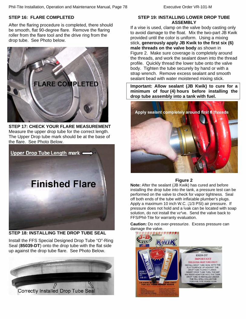
Phil-Tite Installation, Operation and Maintenance Manual, Page 78 Executive Order VR-101-M
STEP 16: FLARE COMPLETED
After the flaring procedure is completed, there should be smooth, flat 90-degree flare. Remove the flaring roller from the flare tool and the drive ring from the drop tube. See Photo below.
STEP 17: CHECK YOUR FLARE MEASUREMENT Measure the upper drop tube for the correct length. The Upper Drop tube mark should be at the base of the flare. See Photo Below.
STEP 18: INSTALLING THE DROP TUBE SEAL
Install the FFS Special Designed Drop Tube “O”-Ring Seal (85039-DT) onto the drop tube with the flat side up against the drop tube flare. See Photo Below.
STEP 19: INSTALLING LOWER DROP TUBE ASSEMBLY
If a vise is used, clamp on the valve body casting only to avoid damage to the float. Mix the two-part JB Kwik provided until the color is uniform. Using a mixing stick, generously apply JB Kwik to the first six (6) male threads on the valve body as shown in Figure 2. Make sure coverage is completely around the threads, and work the sealant down into the thread profile. Quickly thread the lower tube onto the valve body. Tighten the tube securely by hand or with a strap wrench. Remove excess sealant and smooth sealant bead with water moistened mixing stick.
Important: Allow sealant (JB Kwik) to cure for a minimum of four (4) hours before installing the drop tube assembly into a tank with fuel.
Figure 2 Note: After the sealant (JB Kwik) has cured and before installing the drop tube into the tank, a pressure test can be performed on the valve to check for vapor tightness. Seal off both ends of the tube with inflatable plumber’s plugs. Apply a maximum 10 inch W.C. (1/3 PSI) air pressure. If pressure does not hold and a leak can be located with soap solution, do not install the valve. Send the valve back to FFS/Phil-Tite for warranty evaluation.
Caution: Do not over-pressurize. Excess pressure can damage the valve.

Phil-Tite Installation, Operation and Maintenance Manual, Page 79 Executive Order VR-101-M
STEP 20: CUTTING LOWER END OF DROP TUBE Measuring from the underside of the inlet tube flange, mark the overall length of the drop tube a distance of (B) minus 6 inches. Determine dimension (B) from the Drop Tube Measurement Worksheet taken in Step 3, Figure 1 (Top of the M/F 4 X 4 Riser Adaptor to the bottom of the tank). Saw/Cut off the excess tube and file off any sharp burrs.
Optional: Install the Tank Bottom Protector on the lower tube (Refer to Installation instructions supplied with the Tank Bottom Protector).
STEP 21: PREPARE TANK RISER FOR OVERFILL VALVE INSERTION
IMPORTANT: Inspect the tank riser pipe for any foreign material. Over spray from tank relining or any internal burrs inside of pipe must be removed prior to installation. Failure to have an unobstructed tank riser pipe may prevent proper installation or operation of the valve. Thoroughly clean top of tank riser pipe.
Important: Before installing the drop tube, allow the sealant to cure for minimum of four (4) hours.
STEP 22: REMOVE ELASTIC BAND Check the exposed floats for freedom of movement. If floats drag, inspect guide bar for damage. Both of the floats should be free to move up and down without drag. STEP 23: INSTALL THE DROP TUBE Make sure the special drop tube “O” Ring (85039-DT) is installed correctly. Slowly insert the drop tube into the tank riser pipe. Do not force the valve into the tank riser pipe. If any obstruction or foreign matter interferes with smooth insertion of the valve, the tank riser pipe must be cleared. WARNING
Failure to follow the assembly and installation instructions or use of excessive force to insert the Autolimiter II® will VOID THE WARRANTY! STEP 24: CHECK INSTALLATION
Insert the drop tube all the way into the tank until the flange and gasket seat onto the top of the Phil-Tite M/F 4 X 4 Riser.
Figure 3
STEP 25: FINAL INSTALLATION Install a Phil-Tite Fill Spill Container according to the manufacturer’s installation instructions. Ensure that the drop tube does not rotate while tightening the Spill Container by observing the position of the deflector. Install a Phil-Tite rotatable swivel adaptor and tighten according to the manufacturer’s installation instructions. (Continued on next page.)
The discharge opening of the fill-pipe must be entirely submerged when the liquid level is six inches above the bottom of the tank.

Phil-Tite Installation, Operation and Maintenance Manual, Page 80 Executive Order VR-101-M
Figure 4
STEP 26: INSTALL WARNING PLATE
Install warning plate around the 4 inch riser pipe below the threaded portion using the stainless steel band clamp.
STEP 27: VALVE REMOVAL
The Over-fill prevention valve can be removed from the tank by removing the Swivel Adaptor and Spill Container. Reinstall per the above instructions.
STEP 28: ELECTRONIC LIQUID LEVEL MONITORING If an electronic level monitor is installed, it must be calibrated to match the top of the EBW Autolimiter II® valve body, correlated to the 95% tank level dimension used during assembly.
PREVENTATIVE MAINTENANCE The EBW Autolimiter II® 708 series is maintenance free. Be sure to fill out the EVR Equipment Warranty form (F-8352) and send in to FFS/Phil-Tite within 30 days of installation. Failure to do so will void the warranty. Annual visual inspection of the installed drop tube for remnants of broken dip sticks or visual damage is recommended. Repairs must be performed by certified individuals. 2006 FFS F-9020 Rev. 2
CAUTION: Do not insert any foreign object(s) into drop tube if flapper is in the closed position. For example a tank level measuring stick. This will damage the valve and void the Warranty. ALWAYS check the valve position before “sticking” the tank. If valve is in the closed position the tank is either over filled and you need to wait until the liquid level goes down or the Autolimiter is damaged and needs to be replaced.
EBW Autolimiter II® Performance Specifications:
This Overfill Prevention Valve was manufactured by FFS and has been tested by FFS to meet the following specifications: “The maximum leak rate does not exceed 0.17 CFH @ 2.00 inches H2Owhen tested in accordance with ARB TP-201.1C or D. Important: Leave these installation instructions and maintenance procedures with the station operator.
Construction Valve Body: Anodized Cast Aluminum Upper Drop Tube: Aluminum Lower Drop Tube: Aluminum Flappers: Die Cast Zinc and Acetal Float: Polyethylene Models
Part Description 708-491-01 Dual point, 5' top tube, 8' bottom tube 708-491-02 Dual point, 5' top tube, 10' bottom tube 708-492-01 Dual point, 10' top tube, 8' bottom tube
708-492-02 Dual point, 10' top tube, 10' bottom tube
708-491-11 ARB Approved, Dual point, 5' top tube, 8' bottom tube
708-491-12 ARB Approved, Dual point, 5' top tube, 10' bottom tube
708-492-11 ARB Approved, Dual point, 10' top tube, 8' bottom tube
708-492-12 ARB Approved, Dual point, 10' top tube, 10' bottom tube
708-491-31 ARB Gas/E85 Approved, Dual point, 5' top tube, 8' bottom tube
708-491-32 ARB Gas/E85 Approved, Dual point, 5' top tube, 10' bottom tube
708-492-31 ARB Gas/E85 Approved, Dual point, 10' top tube, 8' bottom tube
708-492-32 ARB Gas/E85 Approved, Dual point, 10' top tube, 10' bottom tube

Phil-Tite Installation, Operation and Maintenance Manual, Page 81 Executive Order VR-101-M
Example of Warranty Tags for EBW 708-49X- Series
Drop Tube with Mechanical Overfill Prevention Valve (EBW Autolimiter II®)
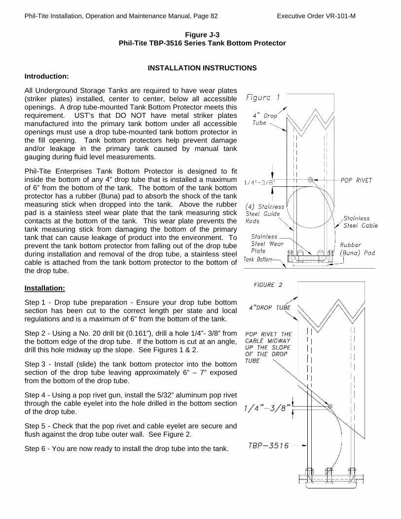
Phil-Tite Installation, Operation and Maintenance Manual, Page 82 Executive Order VR-101-M
Figure J-3 Phil-Tite TBP-3516 Series Tank Bottom Protector
INSTALLATION INSTRUCTIONS Introduction:
All Underground Storage Tanks are required to have wear plates (striker plates) installed, center to center, below all accessible openings. A drop tube-mounted Tank Bottom Protector meets this requirement. UST’s that DO NOT have metal striker plates manufactured into the primary tank bottom under all accessible openings must use a drop tube-mounted tank bottom protector in the fill opening. Tank bottom protectors help prevent damage and/or leakage in the primary tank caused by manual tank gauging during fluid level measurements.
Phil-Tite Enterprises Tank Bottom Protector is designed to fit inside the bottom of any 4” drop tube that is installed a maximum of 6” from the bottom of the tank. The bottom of the tank bottom protector has a rubber (Buna) pad to absorb the shock of the tank measuring stick when dropped into the tank. Above the rubber pad is a stainless steel wear plate that the tank measuring stick contacts at the bottom of the tank. This wear plate prevents the tank measuring stick from damaging the bottom of the primary tank that can cause leakage of product into the environment. To prevent the tank bottom protector from falling out of the drop tube during installation and removal of the drop tube, a stainless steel cable is attached from the tank bottom protector to the bottom of the drop tube. Installation:
Step 1 - Drop tube preparation - Ensure your drop tube bottom section has been cut to the correct length per state and local regulations and is a maximum of 6” from the bottom of the tank.
Step 2 - Using a No. 20 drill bit (0.161”), drill a hole 1/4”- 3/8” from the bottom edge of the drop tube. If the bottom is cut at an angle, drill this hole midway up the slope. See Figures 1 & 2.
Step 3 - Install (slide) the tank bottom protector into the bottom section of the drop tube leaving approximately 6” – 7” exposed from the bottom of the drop tube.
Step 4 - Using a pop rivet gun, install the 5/32” aluminum pop rivet through the cable eyelet into the hole drilled in the bottom section of the drop tube.
Step 5 - Check that the pop rivet and cable eyelet are secure and flush against the drop tube outer wall. See Figure 2.
Step 6 - You are now ready to install the drop tube into the tank.
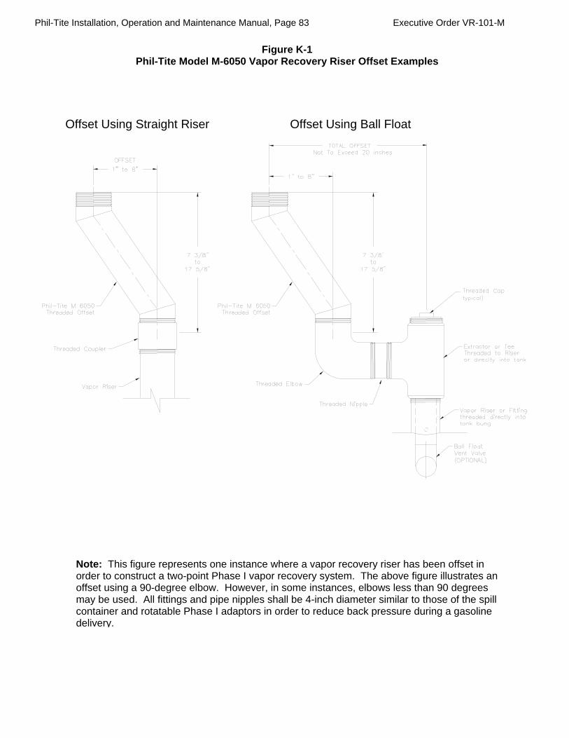
Phil-Tite Installation, Operation and Maintenance Manual, Page 83 Executive Order VR-101-M
Figure K-1 Phil-Tite Model M-6050 Vapor Recovery Riser Offset Examples
Offset Using Ball FloatOffset Using Straight Riser
Note: This figure represents one instance where a vapor recovery riser has been offset in order to construct a two-point Phase I vapor recovery system. The above figure illustrates an offset using a 90-degree elbow. However, in some instances, elbows less than 90 degrees may be used. All fittings and pipe nipples shall be 4-inch diameter similar to those of the spill container and rotatable Phase I adaptors in order to reduce back pressure during a gasoline delivery.
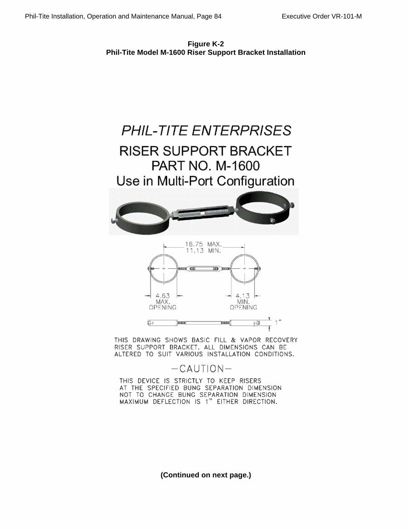
Phil-Tite Installation, Operation and Maintenance Manual, Page 84 Executive Order VR-101-M
Figure K-2
Phil-Tite Model M-1600 Riser Support Bracket Installation
(Continued on next page.)

Phil-Tite Installation, Operation and Maintenance Manual, Page 85 Executive Order VR-101-M
Figure K-2 continued

Phil-Tite Installation, Operation and Maintenance Manual, Page 86 Executive Order VR-101-M
Figure K-2 continued

Phil-Tite Installation, Operation and Maintenance Manual, Page 87 Executive Order VR-101-M
Figure L-1 Typical Phil-Tite Double Fill Configuration

Phil-Tite Installation, Operation and Maintenance Manual, Page 88 Executive Order VR-101-M
Figure L-2 Manway Cover with Platform

Phil-Tite Installation, Operation and Maintenance Manual, Page 89 Executive Order VR-101-M
Figure L-3 Franklin Fueling Systems - Phil-Tite
T-7043 / T-7043-1 Phase I Installation & Removal Tool Kit
(Note: T-7043-1 INCLUDES THE GREEN TORQUE TESTING ADAPTOR)
T-7001 TEE HANDLE ASSEMBLY – 2 PARTS – FITS ALL TOOL ADAPTORS (With the exception of
the green torque testing adaptor) T-7100 RED ADAPTOR – USED TO REMOVE OLD NON-SWIVEL FILL ADAPTORS T-7002-A BLACK ADAPTOR – (HEAVY DUTY) - USED TO INSTALL AND REMOVE PHIL-TITE BLACK
SPILL CONTAINERS (Replaces T-7101 non-heavy duty adaptor) T-7102 ORANGE ADAPTOR – USED TO INSTALL AND REMOVE THE M/F 4X4 RISER ADAPTOR,
AND FILL & VAPOR SWIVEL ADAPTORS T-7103 BLUE ADAPTOR – USE TO REMOVE AND INSTALL OPW’s TALL SWIVEL ADAPTOR T-7104 GREEN ADAPTOR – USED WITH A 3/8” DRIVE DIAL INDICATING TORQUE WRENCH TO
TEST THE STATIC TORQUE OF THE SWIVEL ADAPTOR’S TOPS SC-1502 THREADED TEE HANDLES (2) AND (1) HEX WRENCH – USED TO FACILITATE
REMOVING PHIL-TITE MULTI-PORT MANWAY COVERS
(See Figure next page.)

Phil-Tite Installation, Operation and Maintenance Manual, Page 90 Executive Order VR-101-M
Figure L-3a
Figure of T-7043 Toolkit


![> > [ARB Title] [Work Order #] [ARB Date]](https://img.pdfslide.us/doc/110x75/56649d305503460f94a093ec/wwwdpwstatepaus-wwwdhsstatepaus-arb-title-work-order-arb.jpg)