Embed Size (px)
Citation preview
AR 2000 Operator's Manual 1
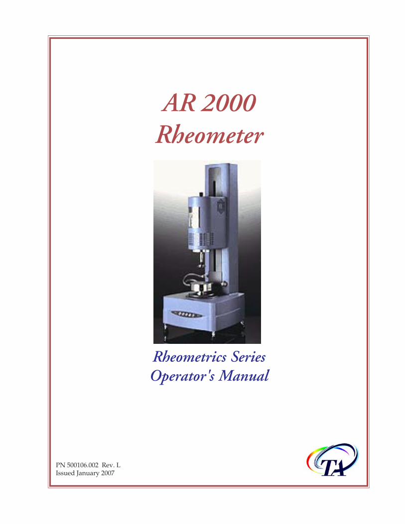
AR 2000Rheometer
Rheometrics SeriesOperator's Manual
PN 500106.002 Rev. LIssued January 2007
AR 2000 Operator's Manual2
© 2000–2007 by TA Instruments109 Lukens DriveNew Castle, DE 19720
Notice
The material contained in this manual, and in the online help for the software used to support this instrument,is believed adequate for the intended use of the instrument. If the instrument or procedures are used for pur-poses other than those specified herein, confirmation of their suitability must be obtained from TA Instruments.Otherwise, TA Instruments does not guarantee any results and assumes no obligation or liability. TA Instru-ments also reserves the right to revise this document and to make changes without notice.
TA Instruments may have patents, patent applications, trademarks, copyrights, or other intellectual propertycovering subject matter in this document. Except as expressly provided in written license agreement from TAInstrument, the furnishing of this document does not give you any license to these patents, trademarks, copy-rights, or other intellectual property.
TA Instruments Operating Software, as well as Module, Data Analysis, and Utility Software and their associ-ated manuals and online help, are proprietary and copyrighted by TA Instruments. Purchasers are granted alicense to use these software programs on the module and controller with which they were purchased. Theseprograms may not be duplicated by the purchaser without the prior written consent of TA Instruments. Eachlicensed program shall remain the exclusive property of TA Instruments, and no rights or licenses are granted tothe purchaser other than as specified above.
AR 2000 Operator's Manual 3
Important: TA Instruments Manual SupplementPlease click on the links below to access important information supplemental to thisGetting Started Guide:
• TA Instruments Trademarks
• TA Instruments Patents
• Other Trademarks
• TA Instruments End-User License Agreement
• TA Instruments Offices
AR 2000 Operator's Manual4
Table of ContentsImportant: TA Instruments Manual Supplement ........................................................................................................ 3
Table of Contents ............................................................................................................................................................. 4
Notes, Cautions, and Warnings .................................................................................................................................. 10
Chapter 1: Introducing the AR 2000 ......................................................................................................................... 11
Overview ........................................................................................................................................................................ 11
Warnings ........................................................................................................................................................................ 11
Attention ......................................................................................................................................................................... 13
Safety and EMC Conformity ........................................................................................................................................ 15
Specifications ................................................................................................................................................................. 15Safety ....................................................................................................................................................................... 15EMC ......................................................................................................................................................................... 15
La sûreté et EMC Conformité ....................................................................................................................................... 16
Spécifications ................................................................................................................................................................. 16Sûreté ....................................................................................................................................................................... 16EMC ......................................................................................................................................................................... 16Lifting and Carrying Instructions ........................................................................................................................ 17Electrical Safety ...................................................................................................................................................... 17Liquid Nitrogen Safety .......................................................................................................................................... 18
Handling Liquid Nitrogen ........................................................................................................................................... 19If a Person is Burned by Liquid Nitrogen ............................................................................................................ 19
Chemical Safety ............................................................................................................................................................. 19
Usage Instructions ........................................................................................................................................................ 20
Maintenance and Repair .............................................................................................................................................. 20
Chapter 2: Description of the AR 2000 ..................................................................................................................... 21
Overview ........................................................................................................................................................................ 21A Brief History of Controlled-Stress Rheometers ................................................................................................ 21
TA Instruments AR Rheometers .................................................................................................................................. 22Schematics of the AR 2000 Rheometer ................................................................................................................ 22Instrument Components ........................................................................................................................................ 23

AR 2000 Operator's Manual 5
Chapter 3: Technical Descriptions ............................................................................................................................ 25
Overview ........................................................................................................................................................................ 25
The Air Bearing ............................................................................................................................................................. 25Rotational Mapping .............................................................................................................................................. 26
Auto GapSet Mechanism .............................................................................................................................................. 27Zeroing of the Gap ................................................................................................................................................. 27Closing the Gap ...................................................................................................................................................... 27Thermal Compensation ......................................................................................................................................... 27
Smart Swap™ ................................................................................................................................................................ 28
The Peltier Plate ............................................................................................................................................................. 28
Normal Force Transducer ............................................................................................................................................. 29
Chapter 4: Technical Specifications ......................................................................................................................... 31
Overview ........................................................................................................................................................................ 31
Specifications ................................................................................................................................................................. 31
Chapter 5: Installation and Operation ...................................................................................................................... 35
Overview ........................................................................................................................................................................ 35
Removing the Packaging and Preparing for Installation ......................................................................................... 35
Installation Requirements ............................................................................................................................................ 36
Connecting the System Together .................................................................................................................................. 37Connecting the Rheometer to the Electronics Control Box ................................................................................ 37Connecting the Computerto the Electronics Control Box .................................................................................. 37Connecting Air and Water to the Rheometer ...................................................................................................... 38
Using Smart Swap™ ..................................................................................................................................................... 39Installing the Peltier Plate ..................................................................................................................................... 39Removing the Peltier Plate .................................................................................................................................... 40
Setting Up the Concentric Cylinder System ............................................................................................................... 41Changing the Cup .................................................................................................................................................. 42
Using the ETC ................................................................................................................................................................ 43Installing the Low Temperature Accessory ......................................................................................................... 46Operating Hints ..................................................................................................................................................... 49
Controlling Cooling ........................................................................................................................................ 49Low Temperature System Maintenance ....................................................................................................... 49
General Operating Guidelines ..................................................................................................................................... 50Do ............................................................................................................................................................................. 50Do Not ..................................................................................................................................................................... 50
Keypad Functionality ................................................................................................................................................... 51

AR 2000 Operator's Manual6
Levelling the Rheometer ............................................................................................................................................... 52
Checking Your System .................................................................................................................................................. 52
Calibrating the Rheometer ........................................................................................................................................... 53
Shut-Down Procedure .................................................................................................................................................. 53
Cleaning the Filter Regulator Assembly ..................................................................................................................... 54
Chapter 6: Measuring Systems .................................................................................................................................. 55
Overview ........................................................................................................................................................................ 55
General Description ...................................................................................................................................................... 55Geometry Materials ................................................................................................................................................ 55
Stainless Steel .................................................................................................................................................. 55Aluminium ...................................................................................................................................................... 55Plastic ............................................................................................................................................................... 56
Cone and Plate ............................................................................................................................................................... 56
Parallel Plate .................................................................................................................................................................. 57
Concentric Cylinders .................................................................................................................................................... 58
Using the Stress and Shear Rate Factors .................................................................................................................... 59
Choosing the Best Geometry ........................................................................................................................................ 60Cone and Plate/Parallel ........................................................................................................................................ 60Plate Systems .......................................................................................................................................................... 60
Angles .............................................................................................................................................................. 60Diameters ......................................................................................................................................................... 60Material ............................................................................................................................................................ 61
Preventing Solvent Evaporation .................................................................................................................................. 62
Preventing Slippage at Sample/Geometry Interface ................................................................................................. 62
Removing the Air-Bearing Clamp ............................................................................................................................... 63
Attaching a Geometry ................................................................................................................................................... 64
Ensuring that the Sample is Loaded Correctly .......................................................................................................... 65
Chapter 7: Using the Upper Heated Plate ................................................................................................................ 67
Introduction to the Upper Heated Plate ...................................................................................................................... 67
Attaching the Upper Heated Plate to the AR 2000 .................................................................................................... 68Installing the (Optional) Vortex Air Cooler ......................................................................................................... 70Configurations for the Cooling Water .................................................................................................................. 72
Connecting the Cooling Control Unit ........................................................................................................... 73Using Circulating Fluids Other Than Water ............................................................................................... 74
Connecting and Disconnecting the Geometry Holder ....................................................................................... 76
AR 2000 Operator's Manual 7
Connecting the Geometry and Holder .......................................................................................................... 76Removing the Geometry and Holder ............................................................................................................ 76
Configuring the Upper Heated Plate ................................................................................................................... 77
Calibration of the Upper Heated Plate ........................................................................................................................ 78
Clamping the Air Bearing ............................................................................................................................................ 81
Using an Inert Gas Atmosphere .................................................................................................................................. 82
Using the Sample Cover ............................................................................................................................................... 83
Chapter 8: The Pressure Cell ..................................................................................................................................... 85
Overview ........................................................................................................................................................................ 85
Specifications ................................................................................................................................................................. 86Operating Specifications ....................................................................................................................................... 86Safety Specifications .............................................................................................................................................. 86Operational Limits ................................................................................................................................................. 86
Pressure Cell Components ........................................................................................................................................... 87The Pressure Cell Cup ........................................................................................................................................... 88
The Inlet Port ................................................................................................................................................... 88The Pressure Gauge Port ................................................................................................................................ 88Safety Relief Port ............................................................................................................................................. 89
Rotor Assembly ...................................................................................................................................................... 89Magnet Assembly ................................................................................................................................................... 90Pressure Manifold .................................................................................................................................................. 91Requirements for External Pressure Source ........................................................................................................ 92
Installing and Using the Pressure Cell ....................................................................................................................... 93Step 1: Install High-Pressure Piping Manifold .................................................................................................. 94Step 2: Install and Configure Pressure Cell Cup and Rotor .............................................................................. 95Step 3: Positioning Gap and Pressure Cell Calibrations ................................................................................... 97Step 4: Loading a Sample ...................................................................................................................................... 98Step 5: Align Manifold and Make Manifold Connections .............................................................................. 100Step 6: Pressurizing/Depressurizing the Cell and Running Experiments ................................................... 101
Running Experiments in Self-Pressurization Mode ............................................................................................... 102
Running Experiments in External Pressurization Mode ....................................................................................... 104
Maintaining the Cell ................................................................................................................................................... 106Cleaning the Pressure Cell Cup .......................................................................................................................... 106Cleaning the Rotor Assembly ............................................................................................................................. 106
Disassembling the Rotor .............................................................................................................................. 107Reassembling the Rotor ................................................................................................................................ 108
Replacement Parts ....................................................................................................................................................... 110
AR 2000 Operator's Manual8
Chapter 9: AR 2000 Interfacial Accessory .............................................................................................................. 111
Overview ...................................................................................................................................................................... 111
Specifications ............................................................................................................................................................... 112
Setting up the Interfacial Accessory .......................................................................................................................... 113
Calibration and Mapping .......................................................................................................................................... 114Zeroing the Gap ................................................................................................................................................... 114Mapping and Other Calibrations ....................................................................................................................... 114
Experimental Procedure ............................................................................................................................................. 115Determining Each Fluid's Contribution ............................................................................................................ 115Finding the Interface Position ............................................................................................................................. 116
Analyzing the Results ................................................................................................................................................ 118Calculation of the Interfacial Contribution to the Torque ................................................................................ 118Interfacial Shear Stress and Shear Rate Calculation ........................................................................................ 119
Part Numbers ............................................................................................................................................................... 119
References .................................................................................................................................................................... 119
Chapter 10: Do's and Don'ts .................................................................................................................................... 121
Overview ...................................................................................................................................................................... 121DO .......................................................................................................................................................................... 121DON'T ................................................................................................................................................................... 122
Appendix A: Useful Information ............................................................................................................................ 123
Moments of Inertia ...................................................................................................................................................... 123Calculations for Moments of Inertia .................................................................................................................. 123
Cone ................................................................................................................................................................ 123Cylinder ......................................................................................................................................................... 124
Appendix B: Symbols and Units ............................................................................................................................. 125
Appendix C: Geometry Form Factors ..................................................................................................................... 127
Cone/Plates ................................................................................................................................................................. 127Concentric Cylinder Dimensions ....................................................................................................................... 127
Appendix D: LCD Display Messages .................................................................................................................... 129
Power On Messages .................................................................................................................................................... 129Initialising ... ......................................................................................................................................................... 129Bearing overspeed ................................................................................................................................................ 129Bearing pressure too low ..................................................................................................................................... 130Encoder index not found ..................................................................................................................................... 130Nf gauge fault ....................................................................................................................................................... 130Nf temp sensor fault ............................................................................................................................................ 130Operator stop event .............................................................................................................................................. 130Power cable fault .................................................................................................................................................. 130

AR 2000 Operator's Manual 9
Signal cable fault .................................................................................................................................................. 130Temp sys element fault ........................................................................................................................................ 130Temp system environment .................................................................................................................................. 130Temp system sensor fault .................................................................................................................................... 131Other Messages .................................................................................................................................................... 131
Appendix E: TA Instruments ETC Kits .................................................................................................................. 133ETC Torsion Rectangular Kit (543307.901) ....................................................................................................... 133ETC Parallel Plate Kit (543306.901) ................................................................................................................... 133ETC Disp. Parallel Plate Kit (543308.901) ......................................................................................................... 133
Index ............................................................................................................................................................................. 135
AR 2000 Operator's Manual10
Notes, Cautions, and WarningsThe following conventions are used throughout this guide to point out items of importance to you as you readthrough the instructions.
A NOTE highlights important information about equipment or procedures.
A CAUTION emphasizes a procedure that may damage equipment or cause loss ofdata if not followed correctly.
A WARNING indicates a procedure that may be hazardous to the operator or to theenvironment if not followed correctly.
AR 2000 Operator's Manual 11
Chapter 1Introducing the AR 2000
OverviewThe TA Instruments AR 2000 Rheometer is a controlled stress/controlled rate rheometer capable of handlingmany different types of samples, using a range of geometry sizes and types.
This manual relates to all hardware aspects of the AR 2000 Rheometer. For complete information on theoperation of the instrument, you may also have to refer to the relevant software manuals supplied with theinstrument.
This chapter describes some important safety information. Please read this information thoroughly beforeproceeding.
WarningsPlease make sure that you read the following warnings BEFORE using this equipment. This section containsinformation that is vital to the safe operation of the AR 2000.
WARNING: This equipment must not be mounted on a flammable surface if lowflashpoint material is being analyzed.
WARNING: An extraction system may be required if the heating of materials couldlead to liberation of hazardous gasses.
WARNING: It is recommended that this instrument be serviced by trained and skilledTA Instruments personnel at least once a year.
WARNING: There may be a danger of explosion if the lithium battery is incorrectlyreplaced. It should be replaced only with the same type, contact TA Instruments forinformation. Dispose of used batteries according to the battery manufacturers instruc-tions. If in doubt, contact TA Instruments.
WARNING: The material used on the top surface of the Peltier plate is hard, chrome-plated copper and the material used for the 'skirt' of the Peltier is stainless steel.Therefore, use an appropriate cleaning material when cleaning the Peltier plate.
WARNING: The internal components of the AR 2000 ETC are all constructed fromchemically resistant materials, and can therefore be cleaned with standard laboratorysolvents. The only exception is the cladding for the thermocouples, which should notbe immersed in a solvent for long periods. Use a small amount of solvent on a softcloth and wipe the soiled area gently. This procedure should never be conducted atany temperature other than ambient.
AR 2000 Operator's Manual12
WARNING: During the installation or reinstallation of the instrument, ensure that theexternal connecting cables (i.e., data, RS232 etc.) are placed separate from the mainspower cables. Also, ensure that the external connecting cables and the mains powercables are placed away from any hot external parts of the instrument.Note: Ensure that the mains power cable is selected such that it is suitable for theinstrument that is being installed or reinstalled, paying particular attention to thecurrent rating of both the cable and the instrument.
WARNING: Before switching the instrument on, apply the air to the instrument andswitch on the water supply to the Peltier system (if used).
WARNING: During operation, extreme hot or cold surfaces may be exposed. Takeadequate precautions. Wear safety gloves before removing hot or cold geometries.
WARNING: Liquid nitrogen can cause rapid suffocation without warning. Store anduse in an area with adequate ventilation. Do not vent liquid nitrogen in confinedspaces. Do not enter confined spaces where nitrogen gas may be present unless thearea is well ventilated. The warning above applies to the use of liquid nitrogen.Oxygen depletion sensors are sometimes utilized where liquid nitrogen is in use.
WARNING: The various surfaces and pipes of the ETC and the supply Dewar can getcold during use. These cold surfaces cause condensation and, in some cases, frost tobuild up. This condensation may drip to the floor. Provisions to keep the floor dryshould be made. If any moisture does drip to the floor, be sure to clean it up promptlyto prevent a slipping hazard.
WARNING: Always unplug the instrument before performing any maintenance.
WARNING: No user serviceable parts are contained in the rheometer. Maintenanceand repair must be performed by TA Instruments or other qualified service personnelonly.
WARNING: This instrument must be connected to an earthed (grounded) powersupply. If this instrument is used with an extension lead, the earth (ground) continuitymust be maintained.
AR 2000 Operator's Manual 13
AttentionCet instrument ne doit être en aucun cas installé sur une surface inflammable lors del'analyse d'échantillons ayant un faible point d'éclair.
Une bouche d'extraction est nécessaire lors de la combustion de matériaux libérantdes gaz toxiques.
Il est recommendé que cet appareil soit révisé au moins une fois par an par uningénieur TA Instruments.
Les piles au lithium de rechange doivent être impérativement du même type quecelles d'origine. Dans le cas contraire, un risque d'explosion reste possible. Pour plusd'informations, contacter TA Instruments.Ne pas jeter de piles au lithium usagées. Celles-ci doivent être recyclées.
La surface supérieure en cuivre de la plaque Peltier est recouverte de chrome. Et lasurface latérale est recouverte d'acier. Il est important d'utiliser des produits adéquats,lors du nettoyage du Peltier, qui n'altérerons pas ces deux matériaux.
Les composants internes du four (ETC) monté sur l'AR2000 sont conçus pour résister àtoute attaque chimique. Ils peuvent donc être tous nettoyés, à l'aide de solvantsquelconques, à l'exception du revêtement des thermocouples, qui ne doivent pas,quant à eux, baigner dans un solvant pendant une longue période. Ceux-ci doiventêtre nettoyés a température ambiante en frottant légèrement avec un chiffon imbibéde solvant.
Les cables externes doivent être toujours separés du cable d'alimentation. S'enassurer à chaque installation. De même, tout cable doit être éloigné de toute sourcede chaleur (Peltier…).
Avant toute mise en marche, s'assurer que l'arrivée d'eau pour le Peltier (si utilisé)ainsi que l'arrivée d'air pour le moteur sont connectées et que l'eau et l'air circulent.
Les différentes surfaces, tuyaux de l’ETC ainsi que le reservoir d’azote liquide peuventêtre exposés à de très basses températures pendant l ’utilisation. Ces surfaces froidesprovoquent de la condensation et peuvent même être à l’origine d’une formation deglace. Cette condensation risque de goutter par terre. Afin d’éviter tout accident dû àun sol glissant, il serait préférable de garder le sol aussi sec que possible.
AR 2000 Operator's Manual14
Lors de toute maintenance, couper l'alimentation.
Toute maintenance ou réparation doivent être effectuées par TA Instruments ou unpersonnel de service qualifié.
Cet appareil doit être connecté à la terre. Toute rallonge utilisée avec cet appareildoit comporter une masse de securité.
Utiliser l'azote liquide avec précautions car une utilisation inadéquate peut provoquerdes suffocations. Stocker et utiliser dans une pièce suffisament ventilée. Ne paspénétrer dans une pièce remplie d'azote avant d'en avoir evacué le gaz.
AR 2000 Operator's Manual 15
Safety and EMC ConformitySpecificationsIn order to comply with the European Council Directives, 73/23/EEC (LVD) and 89/336/EEC (EMC Directive),as amended by 93/68/EEC; the AR 2000 has been tested to the following specifications:
SafetyThis equipment has been designed to comply with the following standards on safety:
• EN 61010-1:1993Safety requirements for electrical equipment for measurement, control and laboratory use.EN 61010-1 Amendment 1, 1995EN 61010-1 Amendment 2, 1995
• EN 6101-2-010: 1994Particular requirements for laboratory equipment for the heating of materials.EN 61010-2-010 Amendment 1, 1996
• UL3101-1 First Edition 1993IEC 1010-2-010: 1992
• CAN/CSA-C22.2 No.1010-1: 1992IEC 1010-2-010: 1992
EMC• EN61326-1: 1997
Electrical equipment for measurement, control and laboratory use.Incorporating:EN55011: 1998 Conducted Class BEN55011: 1998 Radiated Class AEN6100-3-2: 1995 Harmonic currentEN6100-3-3: 1995 Voltage flickerEN6100-4-2: 1995 ESDEN6100-4-3: 1996 Radiated RFEN6100-4-4: 1995 Fast Transient/BurstEN6100-4-5: 1995 SurgeEN6100-4-6: 1996 Conducted disturbancesEN6100-4-11: 1994 Voltage dips
• AZ/NZS 2064: 1997
AR 2000 Operator's Manual16
La sûreté et EMC ConformitéSpécificationsAfin de se conformer aux directives du Conseil européen, 73/23/EEC (LVD) et 89/336/EEC (directive d'cEmc),comme modifié par 93/68/EEC; l'Ar 2000 a été testé selon les caractéristiques suivantes:
SûretéCe matériel a été conçu pour être conforme aux normes de sécurité suivantes:
• EN 61010-1:1993Conditions de securité pour l'appareillage de mesures électrique, la commande et l'usage de laboratoire.
EN61010-1 Amendment 1, 1995EN61010-1 Amendment 2, 1995
• EN6101-2-010: 1994Conditions particulières pour le matériel de laboratoire destine au chauffage des matériaux.
EN61010-2-010 Amendment 1, 1996
• UL3101-1 First Edition 1993IEC 1010-2-010: 1992
• CAN/CSA-C22.2 No.1010-1: 1992IEC 1010-2-010: 1992
EMC• EN61326-1: 1997
Conditions de securité pour l'appareillage de mesures électrique, la commande et l'usage de laboratoire.incorporation
EN55011: 1998 Conducted Class BEN55011: 1998 Radiated Class AEN6100-3-2: 1995 Harmonic currentEN6100-3-3: 1995 Voltage flickerEN6100-4-2: 1995 ESDEN6100-4-3: 1996 Radiated RFEN6100-4-4: 1995 Fast Transient/BurstEN6100-4-5: 1995 SurgeEN6100-4-6: 1996 Conducted disturbancesEN6100-4-11: 1994 Voltage dips
• AZ/NZS 2064: 1997
AR 2000 Operator's Manual 17
Lifting and Carrying InstructionsPlease follow these recommendations when you move or lift the instrument and its accessories:
• Before moving the rheometer, you should remove any temperature attachments from the Smart Swap™holder. See Chapter 5 for more information.
• When moving the rheometer, the air-bearing clamp should always be in place, ensuring that the bearingcannot be moved. See Chapter 5 for information on the air-bearing clamp and how it is attached.
• Use two hands to lift the instrument, keeping your back straight as you lift, to avoid possible strain on yourback. You should always use two people to lift the instrument.
• Treat the AR 2000 with the same degree of care you would take with any scientific laboratory instrument.
Electrical SafetyAlways unplug the instrument before performing any maintenance.
Supply Voltage 110 - 240 VacFuse type 2 x F10 A H250vMains Frequency 45 to 65 HzPower 1000 watts
WARNING: Because of the high voltages in this instrument, maintenance and repair ofinternal parts must be performed by TA Instruments or other qualified service person-nel only.
Cet instrument etant sous hautes tensions, l'entretien et la réparation des piècesinternes doivent être effectues exclusivement par TA instruments ou tout autre person-nel de service qualifié.
AR 2000 Operator's Manual18
Liquid Nitrogen SafetyPotential AsphyxiantWARNING: Liquid nitrogen can cause rapid suffocation without warning. Store anduse in an area with adequate ventilation. Do not vent liquid nitrogen in confinedspaces. Do not enter confined spaces where nitrogen gas may be present unless thearea is well ventilated. The warning above applies to the use of liquid nitrogen.Oxygen depletion sensors are sometimes utilized where liquid nitrogen is in use.
Potentiel Agent asphxyiantL'azote liquide peut causer des suffocations rapides. Stocker et utiliser dans une zonedotée d'une ventilation adéquate. Ne pas ventiler d'azote liquide dans des espacesconfinés. Ne pas pénétrer dans des espaces confinés où le gaz d'azote peut êtreprésent à moins de bien aérer la zone. L'avertissement ci-dessus s'applique àl'utilisation de l'azote liquide. Des capteurs d'épuisement d'oxygène sont parfoisutilisés.
Extremes of temperatureDuring operation, extreme hot or cold surfaces may be exposed. Take adequateprecautions. Wear safety gloves before removing hot or cold geometries.
Températures extremes.Lors du fonctionnement, des surfaces extrèmement chaudes ou froides peuvent êtreexposées. Prendre toutes précautions necessaires telles que l'utilisation de gants deprotection avant d'enlever les géométries chaudes ou froides.

AR 2000 Operator's Manual 19
Handling Liquid NitrogenThe ETC uses the cryogenic (low-temperature) agent, liquid nitrogen, for cooling. Because of its low temperature[-195°C (-319°F)], liquid nitrogen will burn the skin. When you work with liquid nitrogen, use the followingprecautions:
Liquid nitrogen evaporates rapidly at room temperature. Be certain that areas where liquid nitrogen is used arewell ventilated to prevent displacement of oxygen in the air.
1. Wear goggles or a face shield, gloves large enough to be removed easily, and a rubber apron. For extraprotection, wear high-topped, sturdy shoes, and leave your trouser legs outside the tops.
2. Transfer the liquid slowly to prevent thermal shock to the equipment. Use containers that have satisfactorylow-temperature properties. Ensure that closed containers have vents to relieve pressure.
3. The purity of liquid nitrogen decreases as the nitrogen evaporates. If much of the liquid in a container hasevaporated, analyze the remaining liquid before using it for any purpose where high oxygen content couldbe dangerous.
The oven inner doors have a trough around the bottom of the element assembly for collection of excess liquidnitrogen. Any excess fluid collected will drain out from the oven at the lower outer edge.
If a Person is Burned by Liquid Nitrogen1. IMMEDIATELY flood the area (skin or eyes) with large quantities
of cool water, then apply cold compresses.
2. If the skin is blistered or if there is a chance of eye infection, takethe person to a doctor IMMEDIATELY.
Chemical SafetyDo not use hydrogen or any other explosive gas with the ETC.
Use of chlorine gas will damage the instrument.
If you are using samples that may emit harmful gases, vent the gases by placing the instrument near an exhaust.
AR 2000 Operator's Manual20
Usage InstructionsBefore connecting the rheometer to auxiliary equipment, you must ensure that you have read the relevantinstallation information. Safety of the rheometer may be impaired if the instrument:
• Shows visible damage• Fails to perform the intended measurements• Has been badly stored• Has been flooded with water• Has been subjected to severe transport stresses.
Maintenance and Repair
CAUTION: Adjustment, replacement of parts, maintenance and repair should becarried out by trained and skilled TA personnel only. The instrument should bedisconnected from the mains before removal of the cover.
Le réglage, le remplacement des pièces, l'entretien et la réparation devraient êtreeffectués exclusivement par le personnel qualifié de TA Instruments. Avant l'ouverturedu châssis, débrancher l'instrument.
WARNING: The cover should only be removed by authorized personnel. Once thecover has been removed, live parts are accessible. Both live and neutral supplies arefused and therefore a failure of a single fuse could still leave some parts live. Theinstrument contains capacitors that may remain charged even after being discon-nected from the supply.
Le châssis doit être retiré exclusivement par le personnel autorisé. Une fois le chassisretiré, les pièces connectées à l'alimentation sont accessibles. L'instrument contientplusieurs fusibles. L'instrument contient des condensateurs qui peuvent rester chargésmême après avoir été débranchés.

AR 2000 Operator's Manual 21
Chapter 2Description of the AR 2000
OverviewThis chapter describes the main components of the rheometer and provides technical information on perfor-mance and design. Please read this chapter thoroughly to become familiar with the nomenclature usedthroughout this manual.
A Brief History ofControlled-Stress RheometersSir Isaac Newton (c.1700) was the first to formulate a mathematical description of a fluid's resistance to deformor flow when a stress was applied to it. He described this resistance as the viscosity. It is mathematicallydescribed as the shear stress divided by the shear rate or strain. Until Couette developed the first rotationalviscometer (c.1890), viscosity was measured using stress driven (gravity) flow. Many of today's techniques stilluse this principle, such as flow cups, U-tubes, capillaries, etc.
The development of an electromechanical instrument, using synchronous motors, and the electronic versions,using controlled speed servomotors, made controlled rate the widely used technique for versatile rheologicalinstruments for many years.
The first controlled-stress instrument, capable of continuous rotation, was developed by Davis, Deer, andWarburton (1968 J.Sci. Instr. 2, I, 933-6) at the London School of Pharmacy. This instrument used an air turbineand an air bearing. In the early 1970's, a second generation of instruments was developed, using an inductionmotor drive to avoid the problems associated with the air turbine. These, however, were restricted to a maxi-mum torque of 5000 µNm.
AR 2000 Operator's Manual22
TA Instruments AR RheometersThe TA Instruments AR Rheometers are fifth-generation instruments that function as either controlled-stress orcontrolled-rate instruments.
The rheometers are designed to fulfill the requirements of measurement as implied by the full meaning of theterm rheology—defined as the "study of the deformation and flow of matter."
Deformation is measured in the nondestructive region of elastic or viscoelastic deformation. This can giveinvaluable information concerning the microscopic interactions in the test material, as well as measuring theshear stress/shear rate relationships at higher stresses.
In the controlled-stress technique, the stress can be applied and released at will, and the actual behavior of thesample can be measured directly. This is not usually possible with conventional controlled-shear rate instru-ments. In addition, most real-life situations can be simulated more accurately using controlled-stress measure-ments.
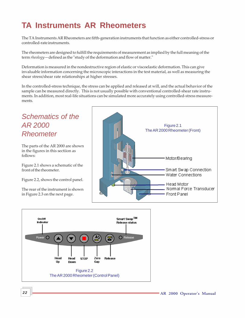
Schematics of theAR 2000RheometerThe parts of the AR 2000 are shownin the figures in this sectiion asfollows:
Figure 2.1 shows a schematic of thefront of the rheometer.
Figure 2.2, shows the control panel.
The rear of the instrument is shownin Figure 2.3 on the next page.
Figure 2.2The AR 2000 Rheometer (Control Panel)
Figure 2.1The AR 2000 Rheometer (Front)
AR 2000 Operator's Manual 23
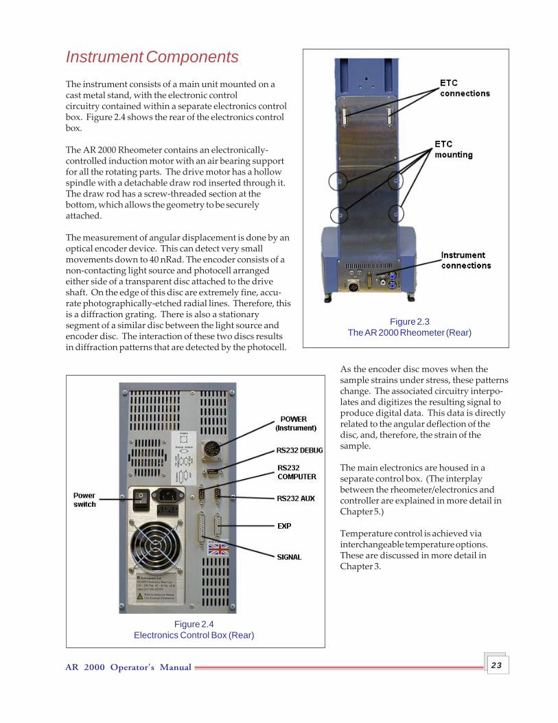
Instrument ComponentsThe instrument consists of a main unit mounted on acast metal stand, with the electronic controlcircuitry contained within a separate electronics controlbox. Figure 2.4 shows the rear of the electronics controlbox.
The AR 2000 Rheometer contains an electronically-controlled induction motor with an air bearing supportfor all the rotating parts. The drive motor has a hollowspindle with a detachable draw rod inserted through it.The draw rod has a screw-threaded section at thebottom, which allows the geometry to be securelyattached.
The measurement of angular displacement is done by anoptical encoder device. This can detect very smallmovements down to 40 nRad. The encoder consists of anon-contacting light source and photocell arrangedeither side of a transparent disc attached to the driveshaft. On the edge of this disc are extremely fine, accu-rate photographically-etched radial lines. Therefore, thisis a diffraction grating. There is also a stationarysegment of a similar disc between the light source andencoder disc. The interaction of these two discs resultsin diffraction patterns that are detected by the photocell.
As the encoder disc moves when thesample strains under stress, these patternschange. The associated circuitry interpo-lates and digitizes the resulting signal toproduce digital data. This data is directlyrelated to the angular deflection of thedisc, and, therefore, the strain of thesample.
The main electronics are housed in aseparate control box. (The interplaybetween the rheometer/electronics andcontroller are explained in more detail inChapter 5.)
Temperature control is achieved viainterchangeable temperature options.These are discussed in more detail inChapter 3.
Figure 2.3The AR 2000 Rheometer (Rear)
Figure 2.4Electronics Control Box (Rear)

AR 2000 Operator's Manual24
AR 2000 Operator's Manual 25
Chapter 3Technical Descriptions
OverviewIn order to fully utilize the advanced capabilities available with the AR 2000 Rheometer, some of the importantcomponents require a more detailed explanation. This chapter describes in detail the design and functions ofthe:
• Air bearing• Auto gap set device• Smart Swap™• Peltier plate• Normal force transducer.
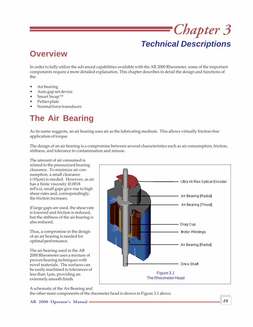
The Air BearingAs its name suggests, an air bearing uses air as the lubricating medium. This allows virtually friction-freeapplication of torque.
The design of an air bearing is a compromise between several characteristics such as air consumption, friction,stiffness, and tolerance to contamination and misuse.
The amount of air consumed isrelated to the pressurized bearingclearance. To minimize air con-sumption, a small clearance(<10µm) is needed. However, as airhas a finite viscosity (0.0018mPa.s), small gaps give rise to highshear rates and, correspondingly,the friction increases.
If large gaps are used, the shear rateis lowered and friction is reduced,but the stiffness of the air bearing isalso reduced.
Thus, a compromise in the designof an air bearing is needed foroptimal performance.
The air bearing used in the AR2000 Rheometer uses a mixture ofproven bearing techniques withnovel materials. The surfaces canbe easily machined to tolerances ofless than 1µm, providing anextremely smooth finish.
A schematic of the Air Bearing andthe other main components of the rheometer head is shown in Figure 3.1 above.
Figure 3.1The Rheometer Head
AR 2000 Operator's Manual26
The bearing is designed to be virtually friction- free, so that it moves under the smallest of forces. Even extremelysmall manufacturing variations in the bearing can be sufficient to make it rotate. Therefore, to ensure that thebearing rotation is steady throughout a full 360°, a process called Rotational Mapping, which is explained inthe next section, is carried out.
Rotational MappingAs explained previously, any real air bearing will have small variations in behavior around one revolution ofthe shaft.
By combining the absolute angular position data from the optical encoder with microprocessor control of themotor, these small variations can be mapped automatically and stored, since the variations are consistent overtime, unless changes occur in the air bearing.The microprocessor can allow for these automatically by carrying out a baseline correction of the torque. Thisresults in a very wide bearing operating range, without operator intervention; i.e., a confidence check in bearingperformance.
Instructions for performing the rotational mapping can be found in the Rheology Advantage™ online help.

AR 2000 Operator's Manual 27
Auto GapSet MechanismThe auto gap set facility has three major functions, as follows:
• Automatic setting of gaps via software• Programmed gap closure• Thermal gap compensation.
These features are described in more detail on the following pages.
Zeroing of the GapIt is important that you use a reproducible gap zeroing technique to reduce errors from such factors as operator-to-operator techniques. The automation of gap zeroing on the rheometer minimizes these errors.
Closing the GapOnce you have set the gap and loaded the sample, the head is lowered. The velocity and deceleration of thehead as it is lowered is controlled via the 'automatic gap options' set in the Rheology Advantage software.There are four closure options available with the AR 2000 Rheometer-—Standard, Linear, Exponential, andNormal Force. The options available are described in detail in the online help for the rheology software.
CAUTION: Keep hands and fingers away from the plate during head move-ment.
S'assurer que les mains ou doigts ne soient pas entre le peltier et lagéométrie lors du mouvement de la tête de l'instrument.
Thermal CompensationWhen a wide temperature range is used for an experiment, the metallic rheometer parts and the measurementgeometries can heat or cool causing expansion or contraction of the measurement system gap. A typical expan-sion value for stainless steel geometries is 0.5 µm°C-1. The auto gap-set facility compensates for these changes.Therefore, regardless of temperature, you can be confident that the gap remains constant.
AR 2000 Operator's Manual28
Smart Swap™The AR2000 features "Smart Swap" technology that automatically senses the temperature control system presentand configures the rheometer operating software accordingly, loading all relevant calibration data. The use ofthis feature is covered later in Chapter 5.
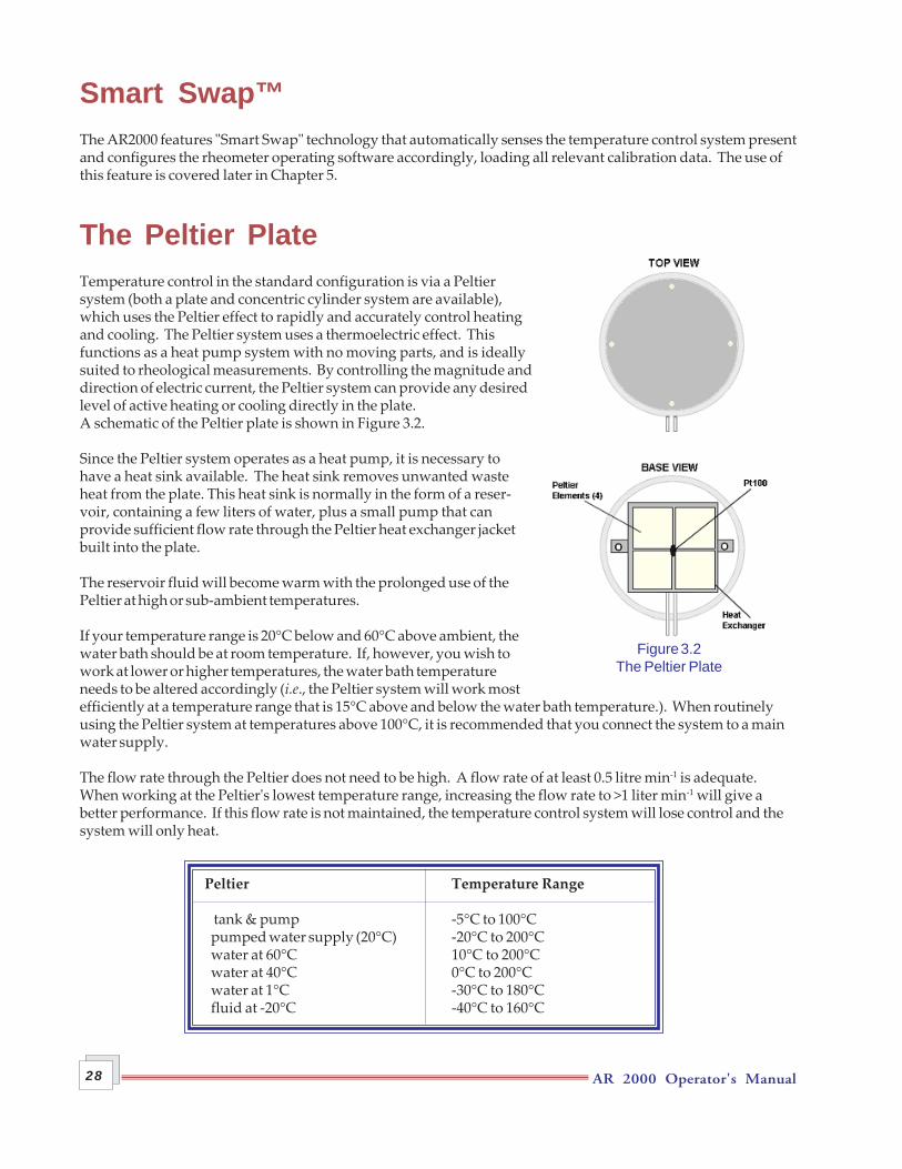
The Peltier PlateTemperature control in the standard configuration is via a Peltiersystem (both a plate and concentric cylinder system are available),which uses the Peltier effect to rapidly and accurately control heatingand cooling. The Peltier system uses a thermoelectric effect. Thisfunctions as a heat pump system with no moving parts, and is ideallysuited to rheological measurements. By controlling the magnitude anddirection of electric current, the Peltier system can provide any desiredlevel of active heating or cooling directly in the plate.A schematic of the Peltier plate is shown in Figure 3.2.
Since the Peltier system operates as a heat pump, it is necessary tohave a heat sink available. The heat sink removes unwanted wasteheat from the plate. This heat sink is normally in the form of a reser-voir, containing a few liters of water, plus a small pump that canprovide sufficient flow rate through the Peltier heat exchanger jacketbuilt into the plate.
The reservoir fluid will become warm with the prolonged use of thePeltier at high or sub-ambient temperatures.
If your temperature range is 20°C below and 60°C above ambient, thewater bath should be at room temperature. If, however, you wish towork at lower or higher temperatures, the water bath temperatureneeds to be altered accordingly (i.e., the Peltier system will work mostefficiently at a temperature range that is 15°C above and below the water bath temperature.). When routinelyusing the Peltier system at temperatures above 100°C, it is recommended that you connect the system to a mainwater supply.
The flow rate through the Peltier does not need to be high. A flow rate of at least 0.5 litre min-1 is adequate.When working at the Peltier's lowest temperature range, increasing the flow rate to >1 liter min-1 will give abetter performance. If this flow rate is not maintained, the temperature control system will lose control and thesystem will only heat.
Peltier Temperature Range
tank & pump -5°C to 100°Cpumped water supply (20°C) -20°C to 200°Cwater at 60°C 10°C to 200°Cwater at 40°C 0°C to 200°Cwater at 1°C -30°C to 180°Cfluid at -20°C -40°C to 160°C
Figure 3.2The Peltier Plate
AR 2000 Operator's Manual 29
CAUTION: The Peltier Plate may be damaged by operating the instrument without aflow of water through the Peltier system. There is a Peltier Overheat protectiondevice that will activate if the device becomes too hot.
Sans écoulement d'eau, le système Peltier peut être endommagé. Un dispositif deprotection a été conçu pour se déclencher en cas de surchauffe.
Normal Force TransducerWhen a viscoelastic liquid is sheared, a force can be generated along the axis of rotation of a cone or parallelplate geometry. For this to happen, the structure responsible for the elasticity must not be completely disruptedby steady shear.
For this reason, colloids, suspensions, etc., although elastic at rest, become effectively inelastic under steadyshear and can show negative normal forces due to inertial effects. However, polymer solutions and melts, andproducts incorporating them, are typically elastic under shear because of the long lifetime of the molecularentanglement.
Normal force measurements are made with cone and plate or parallel plate geometries; therefore, it is importantto use a method to detect the force that does not allow significant changes in the gap. This would result in theactual shear rate varying with normal force, due to deflections of the force-detecting component.
The AR 2000 Rheometer keeps the upper geometry positioned as accurately as is possible with an air bearing,and movement is kept to an absolute minimum. This ensures good bearing performance.
The force is detected on the static lower measuring geometry assembly using high sensitivity load cell technol-ogy. This results in a fast response, wide range signal, which is easy to calibrate, and has a genuine normalforce measurement capability.
CAUTION: During sample loading and measurement, the normal force transducer isprotected from overload. However, take care when cleaning or attaching accessoriesto the lower plate that you do not exceed the maximum normal force.
Le capteur de force normale est protégé contre toute surcharge. Cependant, prendresoin de ne pas dépasser la force normale maximale lors de toute manipulation(nettoyage, changement de plaque…).

AR 2000 Operator's Manual30
AR 2000 Operator's Manual 31
Chapter 4Technical Specifications
OverviewThis chapter contains the technical specifications for the AR 2000 Rheometer. You can obtain further informa-tion from your local Sales Representative.
SpecificationsThe following specifications apply to the TA Instruments AR 2000 Rheometer:
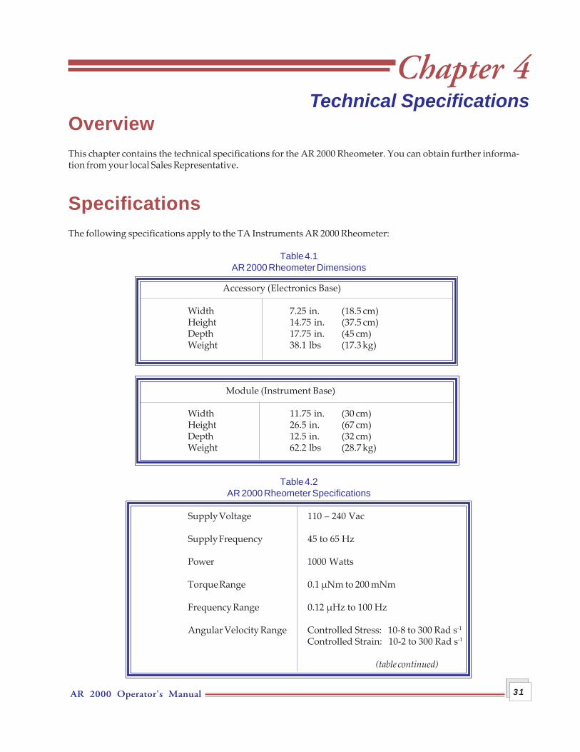
Table 4.1AR 2000 Rheometer Dimensions
Accessory (Electronics Base)
Width 7.25 in. (18.5 cm)Height 14.75 in. (37.5 cm)Depth 17.75 in. (45 cm)Weight 38.1 lbs (17.3 kg)
Module (Instrument Base)
Width 11.75 in. (30 cm)Height 26.5 in. (67 cm)Depth 12.5 in. (32 cm)Weight 62.2 lbs (28.7 kg)
Table 4.2AR 2000 Rheometer Specifications
Supply Voltage 110 – 240 Vac
Supply Frequency 45 to 65 Hz
Power 1000 Watts
Torque Range 0.1 µNm to 200 mNm
Frequency Range 0.12 µHz to 100 Hz
Angular Velocity Range Controlled Stress: 10-8 to 300 Rad s-1
Controlled Strain: 10-2 to 300 Rad s-1
(table continued)
AR 2000 Operator's Manual32
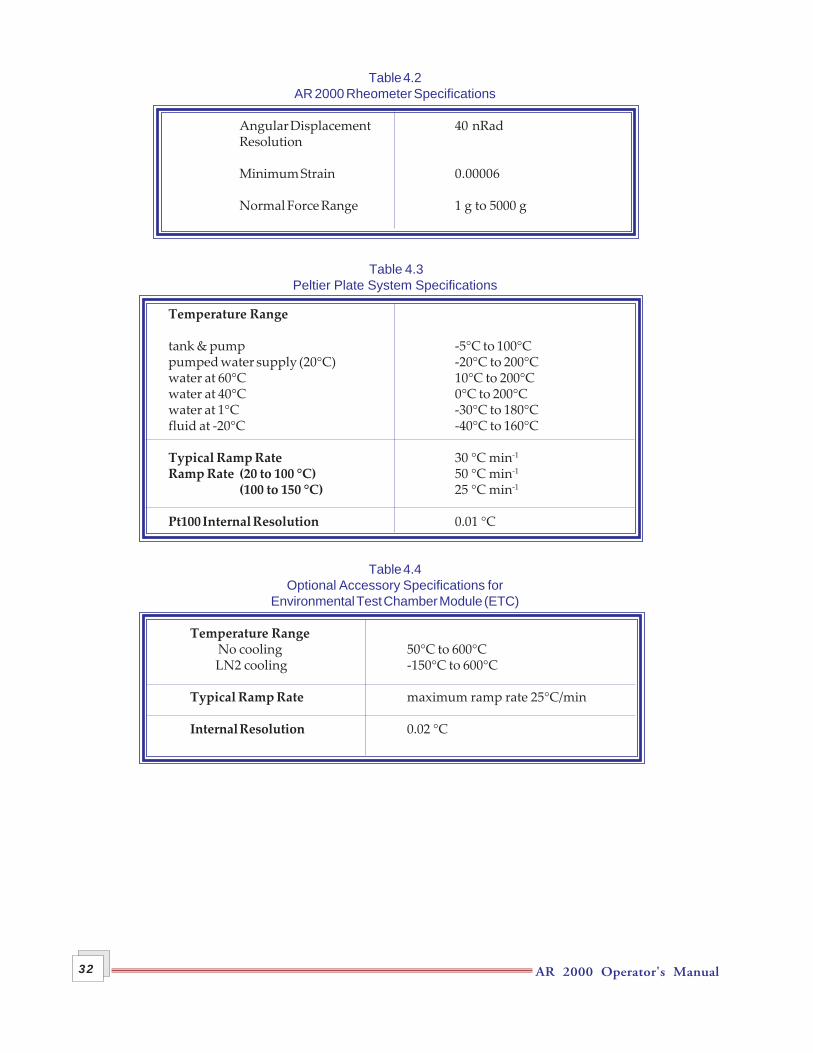
Table 4.2AR 2000 Rheometer Specifications
Angular Displacement 40 nRadResolution
Minimum Strain 0.00006
Normal Force Range 1 g to 5000 g
Table 4.3Peltier Plate System Specifications
Temperature Range
tank & pump -5°C to 100°Cpumped water supply (20°C) -20°C to 200°Cwater at 60°C 10°C to 200°Cwater at 40°C 0°C to 200°Cwater at 1°C -30°C to 180°Cfluid at -20°C -40°C to 160°C
Typical Ramp Rate 30 °C min-1
Ramp Rate (20 to 100 °C) 50 °C min-1
(100 to 150 °C) 25 °C min-1
Pt100 Internal Resolution 0.01 °C
Table 4.4Optional Accessory Specifications for
Environmental Test Chamber Module (ETC)
Temperature Range No cooling 50°C to 600°CLN2 cooling -150°C to 600°C
Typical Ramp Rate maximum ramp rate 25°C/min
Internal Resolution 0.02 °C
AR 2000 Operator's Manual 33
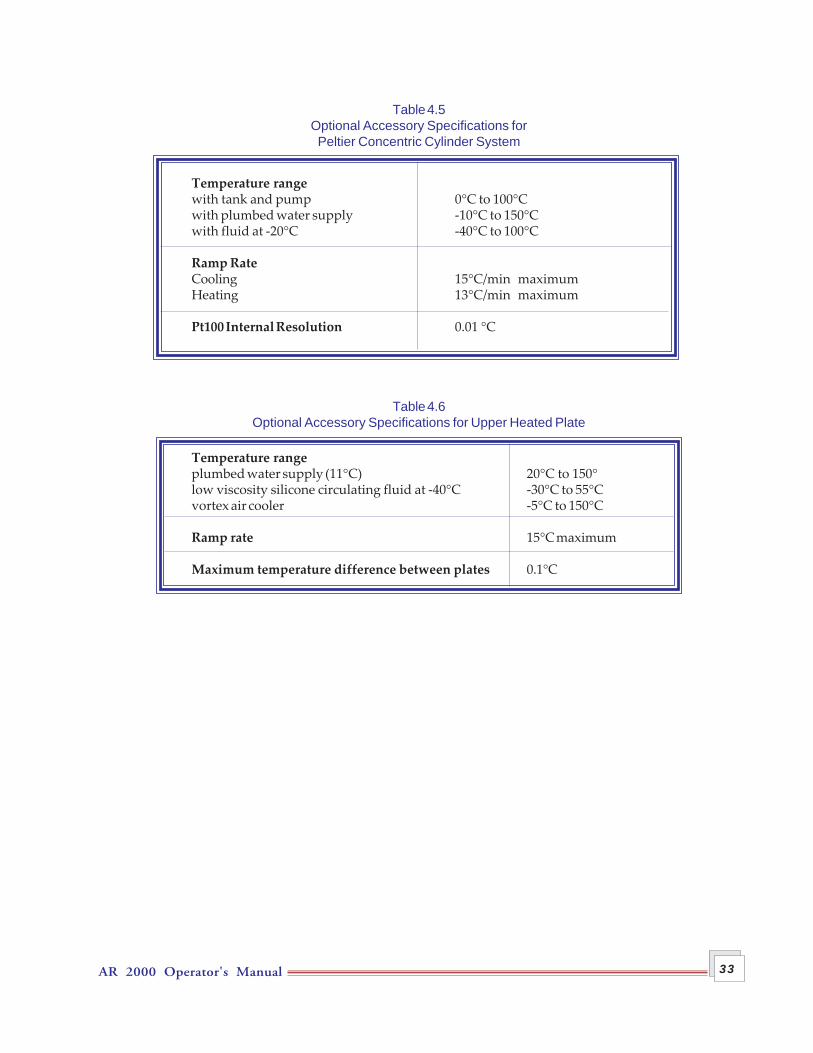
Table 4.5Optional Accessory Specifications forPeltier Concentric Cylinder System
Temperature rangewith tank and pump 0°C to 100°Cwith plumbed water supply -10°C to 150°Cwith fluid at -20°C -40°C to 100°C
Ramp RateCooling 15°C/min maximumHeating 13°C/min maximum
Pt100 Internal Resolution 0.01 °C
Table 4.6Optional Accessory Specifications for Upper Heated Plate
Temperature rangeplumbed water supply (11°C) 20°C to 150°low viscosity silicone circulating fluid at -40°C -30°C to 55°Cvortex air cooler -5°C to 150°C
Ramp rate 15°C maximum
Maximum temperature difference between plates 0.1°C

AR 2000 Operator's Manual34
AR 2000 Operator's Manual 35
Chapter 5Installation and Operation
OverviewNormally the installation of your new system will be carried out by a member of the TA Instruments sales orservice staff, or their appointed agents, and it will be ready for you to use. However, should you need to installor relocate the instrument, this chapter provides the necessary instructions.
Removing the Packagingand Preparing for InstallationIf needed, the first step is to carefully remove all items from any and all packaging. We recommend that youretain all packaging materials in case the instrument has to be shipped back to TA Instruments at some point inthe future (for example, in the case of some upgrades).
Please follow these recommendations when you move or lift the instrument and its accessories:
• Always remove the temperature control module from the rheometer before attempting to move it. Details onhow to do this can be found later in this section(Smart Swap™).
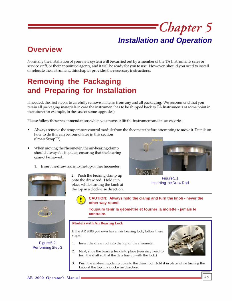
• When moving the rheometer, the air-bearing clampshould always be in place, ensuring that the bearingcannot be moved.
1. Insert the draw rod into the top of the rheometer.
2. Push the bearing clamp uponto the draw rod. Hold it inplace while turning the knob atthe top in a clockwise direction.
CAUTION: Always hold the clamp and turn the knob - never theother way round.Toujours tenir la géométrie et tourner la molette - jamais lecontraire.
Figure 5.1Inserting the Draw Rod
Models with Air Bearing Lock
If the AR 2000 you own has an air bearing lock, follow thesesteps:
1. Insert the draw rod into the top of the rheometer.
2. Next, slide the bearing lock into place (you may need toturn the shaft so that the flats line up with the lock.)
3. Push the air-bearing clamp up onto the draw rod. Hold it in place while turning theknob at the top in a clockwise direction.
Figure 5.2Performing Step 3
AR 2000 Operator's Manual36
Installation RequirementsIt is important to select a location for the instrument using the following guidelines.
Choose a location that is...
In
• A temperature-controlled area. (22°C ±4°C, relative humidity 50 ±10%).• A clean environment (indoor use).• An area with ample working and ventilation space around the instrument, approximately 2 meters in
length, with sufficient depth for a computer and its keyboard.
On
• A stable, vibration-free work surface.
Near
• A power outlet. (Mains supply voltage fluctuations not to exceed ±10% of the nominal voltage, installationcategory 2.)
• Your computer.• Sources of compressed lab air and purge gas supply for use during cooling and sub-ambient experiments.
A compressed air supply that is capable of supplying clean, dry, oil free air at an approximate pressure of30 psi (~ 2 Bar) at a flow rate of 50 liters-1. The dew point of the air supply should be -20°C or better.
Away from
• Dusty environment (pollution degree 1).• Exposure to direct sunlight.• Poorly ventilated areas.
After you have decided on the location for your instrument, refer to the following sections to unpack and installthe AR 2000 Rheometer.
NOTE: Internal Fuse: FS1 & FS2 on cmd 069 pcb. It is strongly recommended that theinternal fuse be replaced only by trained and skilled TA Instrument personnel.

AR 2000 Operator's Manual 37
Connecting the System TogetherConnecting the system together should present no problems, as long as you use instructions found in thefollowing sections.
Connecting the Rheometerto the Electronics Control BoxThe Electronics Control Box forms the link between the rheometer andthe computer. All the required processing is done within the control box.The following steps should be followed to connect the two units together(refer to Figure 5.3).
1. Push the female end of the Power cable into the Power port on theback of the rheometer and the other end in the Power port on theback of the control box (Cable A).
2. Push the D-type cable into the Signal port on the back of the rheom-eter and connect the other end to the Signal port on the back of thecontrol box (Cable C).
Connecting the Computerto the Electronics Control BoxThe electronics control box and computer are connected via a singleRS232 cable, which is supplied with the system. One end of the cablehas a 9-pin female connector; the other end has a 9-pin male connector.
1. Push the 9-pin female connector into the 9-pin socket marked'Computer' on the back plate of the controller (Cable B, Figure 5.3).
2. Push the 9-pin male connector into the serial port socket on the backof the socket on the computer.
NOTE: You must configure the software for the appropriate communications port—refer to theonline help for instructions on how to do this.
Vous devez configurer le logiciel en fonction du port de transmissions utilisé—se référer à l'aidefournie dans le logiciel.
Figure 5.3Cable Connections

AR 2000 Operator's Manual38
Connecting Air and Water to the RheometerRefer to Figure 5.4 on the previous page for information on the location of the relevant connections in theinstructions below.
1. Connect a supply of cooling water the flow and return connections at the rear of the rheometer
2. Connect the air supply (from the air regulator assembly) to the 'air in' connection.
AR 2000 Operator's Manual 39
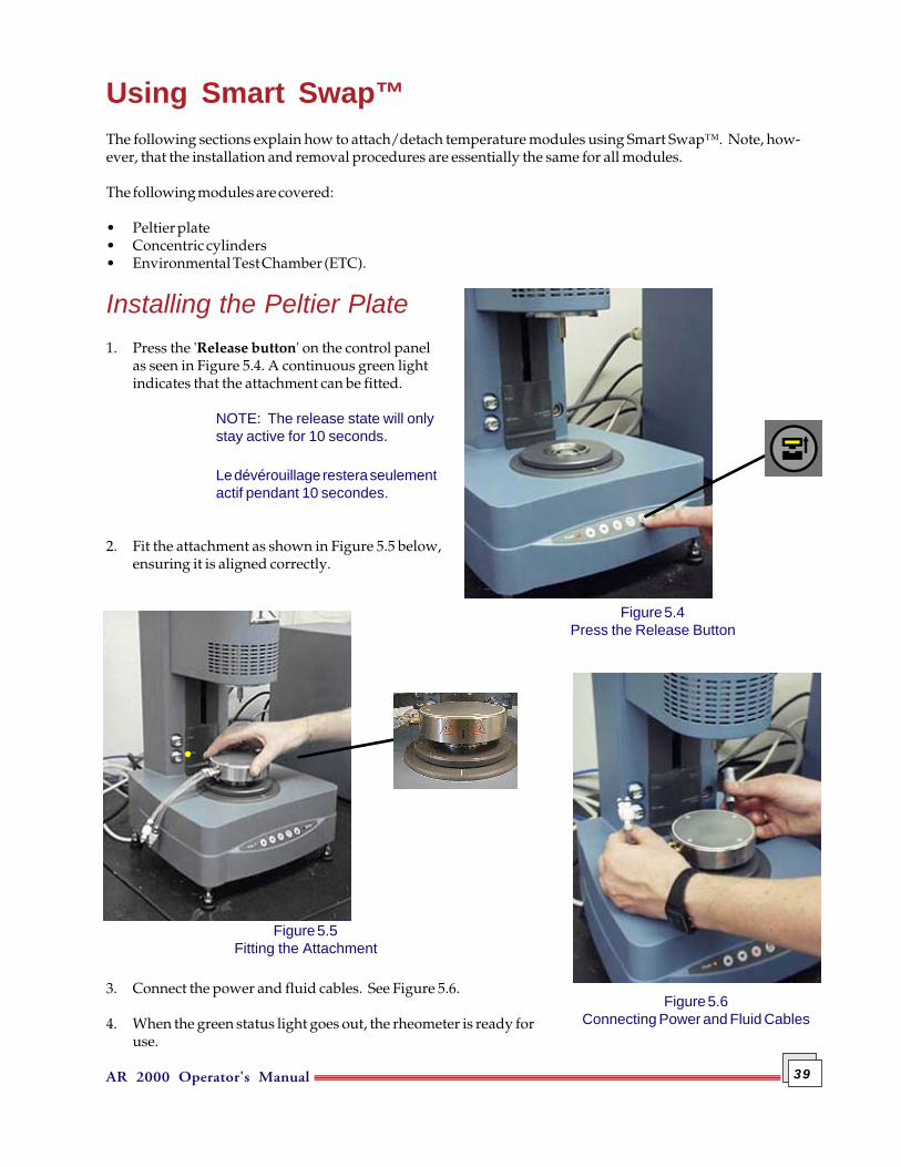
Using Smart Swap™The following sections explain how to attach/detach temperature modules using Smart Swap™. Note, how-ever, that the installation and removal procedures are essentially the same for all modules.
The following modules are covered:
• Peltier plate• Concentric cylinders• Environmental Test Chamber (ETC).
Installing the Peltier Plate1. Press the 'Release button' on the control panel
as seen in Figure 5.4. A continuous green lightindicates that the attachment can be fitted.
NOTE: The release state will onlystay active for 10 seconds.
Le dévérouillage restera seulementactif pendant 10 secondes.
2. Fit the attachment as shown in Figure 5.5 below,ensuring it is aligned correctly.
3. Connect the power and fluid cables. See Figure 5.6.
4. When the green status light goes out, the rheometer is ready foruse.
Figure 5.5Fitting the Attachment
Figure 5.4Press the Release Button
Figure 5.6Connecting Power and Fluid Cables
AR 2000 Operator's Manual40
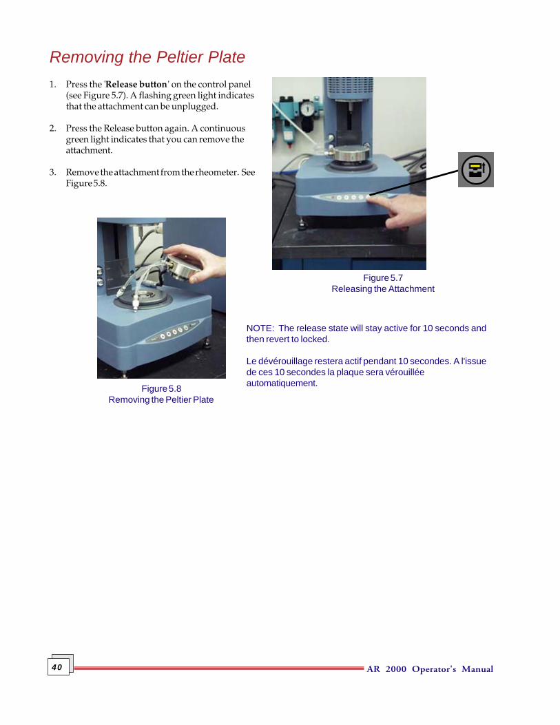
Removing the Peltier Plate1. Press the 'Release button' on the control panel
(see Figure 5.7). A flashing green light indicatesthat the attachment can be unplugged.
2. Press the Release button again. A continuousgreen light indicates that you can remove theattachment.
3. Remove the attachment from the rheometer. SeeFigure 5.8.
NOTE: The release state will stay active for 10 seconds andthen revert to locked.
Le dévérouillage restera actif pendant 10 secondes. A l'issuede ces 10 secondes la plaque sera vérouilléeautomatiquement.
Figure 5.7Releasing the Attachment
Figure 5.8Removing the Peltier Plate
AR 2000 Operator's Manual 41
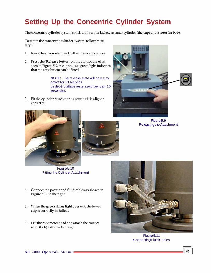
Setting Up the Concentric Cylinder SystemThe concentric cylinder system consists of a water jacket, an inner cylinder (the cup) and a rotor (or bob).
To set up the concentric cylinder system, follow thesesteps:
1. Raise the rheometer head to the top most position.
2. Press the 'Release button' on the control panel asseen in Figure 5.9. A continuous green light indicatesthat the attachment can be fitted.
NOTE: The release state will only stayactive for 10 seconds.Le dévérouillage restera actif pendant 10secondes.
3. Fit the cylinder attachment, ensuring it is alignedcorrectly.
4. Connect the power and fluid cables as shown inFigure 5.11 to the right.
5. When the green status light goes out, the lowercup is correctly installed.
6. Lift the rheometer head and attach the correctrotor (bob) to the air bearing.
Figure 5.9Releasing the Attachment
Figure 5.10Fitting the Cylinder Attachment
Figure 5.11Connecting Fluid Cables
AR 2000 Operator's Manual42
Figure 5.13Changing the Cup
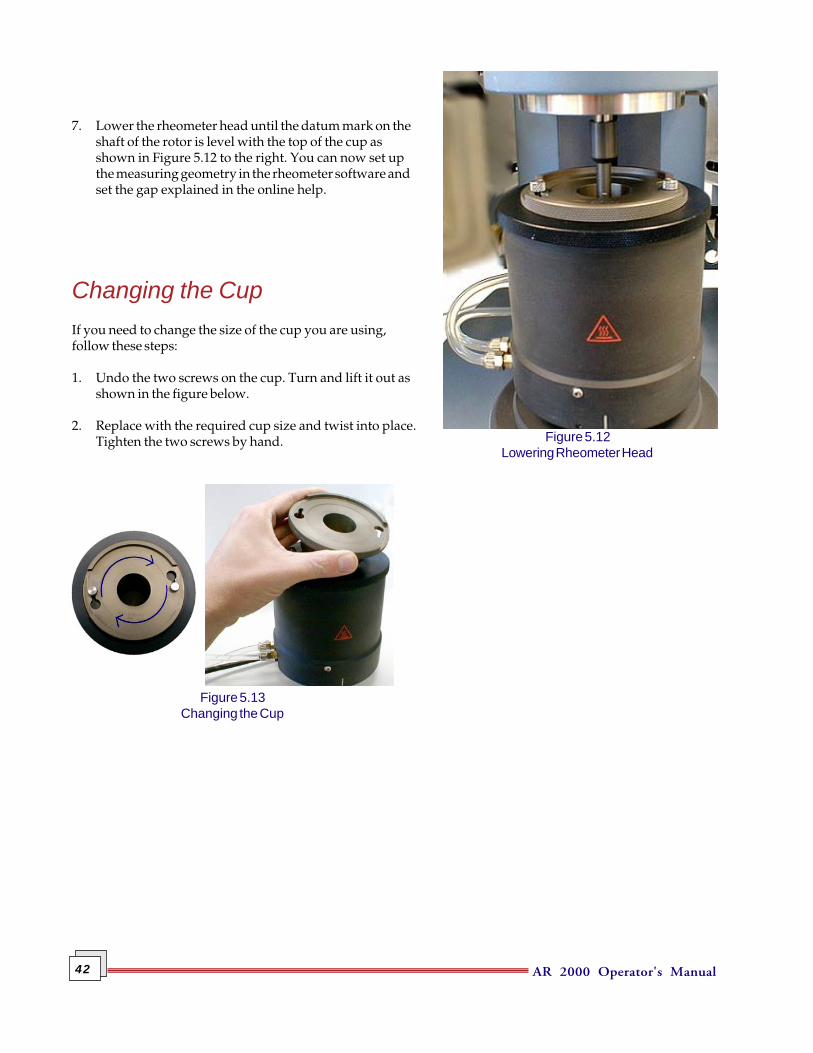
7. Lower the rheometer head until the datum mark on theshaft of the rotor is level with the top of the cup asshown in Figure 5.12 to the right. You can now set upthe measuring geometry in the rheometer software andset the gap explained in the online help.
Changing the CupIf you need to change the size of the cup you are using,follow these steps:
1. Undo the two screws on the cup. Turn and lift it out asshown in the figure below.
2. Replace with the required cup size and twist into place.Tighten the two screws by hand. Figure 5.12
Lowering Rheometer Head
AR 2000 Operator's Manual 43
Using the ETCThis section provides information on how to install and set up the Environ-mental Testing Chamber (ETC). For more information on the ETC, see theRheology Advantage online help.
1. Turn on the rheometer and move the rheometer head up to the maxi-mum height. (Use the 'Head UP' button, located on the instrumentcontrol panel.)
2. Fit the air-bearing clamp to the rheometer (see the start of this chapter).
3. Turn off the power to the rheometer control box.
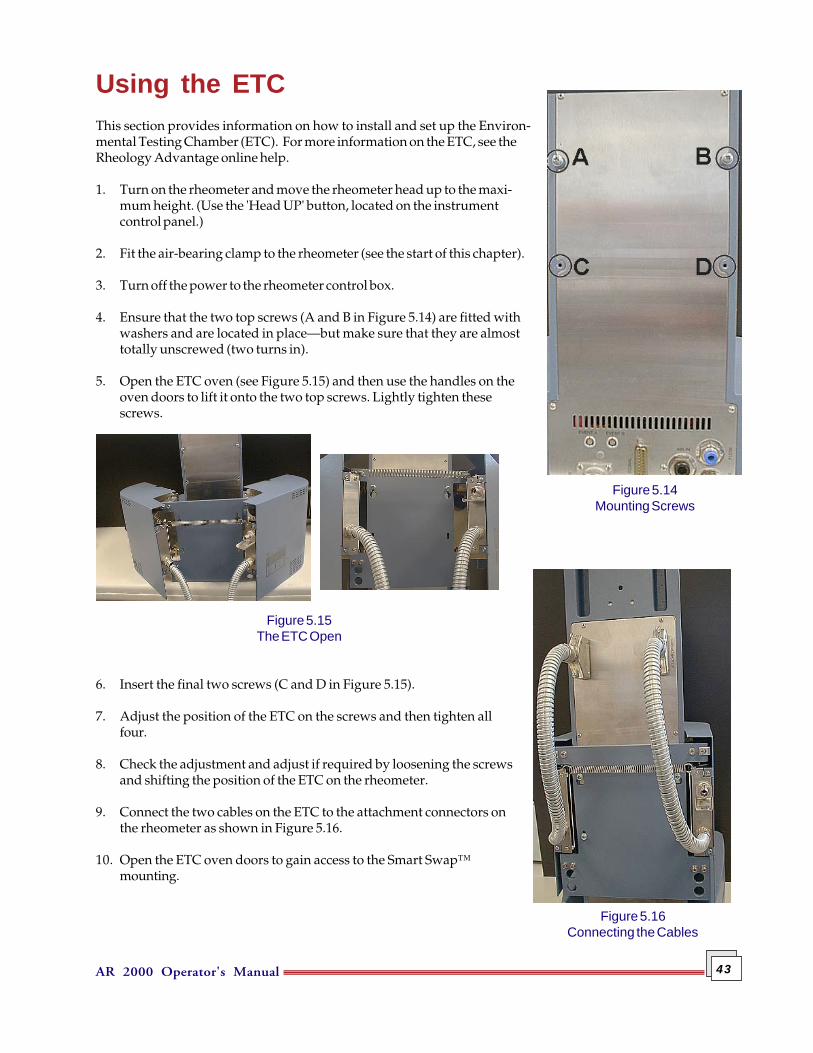
4. Ensure that the two top screws (A and B in Figure 5.14) are fitted withwashers and are located in place—but make sure that they are almosttotally unscrewed (two turns in).
5. Open the ETC oven (see Figure 5.15) and then use the handles on theoven doors to lift it onto the two top screws. Lightly tighten thesescrews.
6. Insert the final two screws (C and D in Figure 5.15).
7. Adjust the position of the ETC on the screws and then tighten allfour.
8. Check the adjustment and adjust if required by loosening the screwsand shifting the position of the ETC on the rheometer.
9. Connect the two cables on the ETC to the attachment connectors onthe rheometer as shown in Figure 5.16.
10. Open the ETC oven doors to gain access to the Smart Swap™mounting.
Figure 5.14Mounting Screws
Figure 5.15The ETC Open
Figure 5.16Connecting the Cables
AR 2000 Operator's Manual44
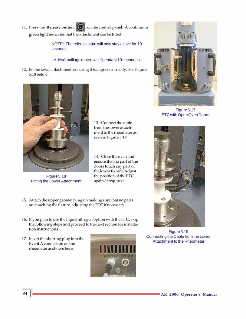
Figure 5.18Fitting the Lower Attachment
Figure 5.19Connecting the Cable from the Lower
Attachment to the Rheometer
11. Press the 'Release button,' , on the control panel. A continuous
green light indicates that the attachment can be fitted.
NOTE: The release state will only stay active for 10seconds.
Le dévérouillage restera actif pendant 10 secondes.
12. Fit the lower attachment, ensuring it is aligned correctly. See Figure5.18 below.
13. Connect the cablefrom the lower attach-ment to the rheometer asseen in Figure 5.19.
14. Close the oven andensure that no part of thedoors touch any part ofthe lower fixture. Adjustthe position of the ETCagain, if required.
15. Attach the upper geometry, again making sure that no partsare touching the fixture, adjusting the ETC if necessary.
16. If you plan to use the liquid nitrogen option with the ETC, skipthe following steps and proceed to the next section for installa-tion instructions.
17. Insert the shorting plug into theEvent A connection on therheometer as shown here.
Figure 5.17ETC with Open Oven Doors
AR 2000 Operator's Manual 45
Figure 5.20Connecting the Purge Gas
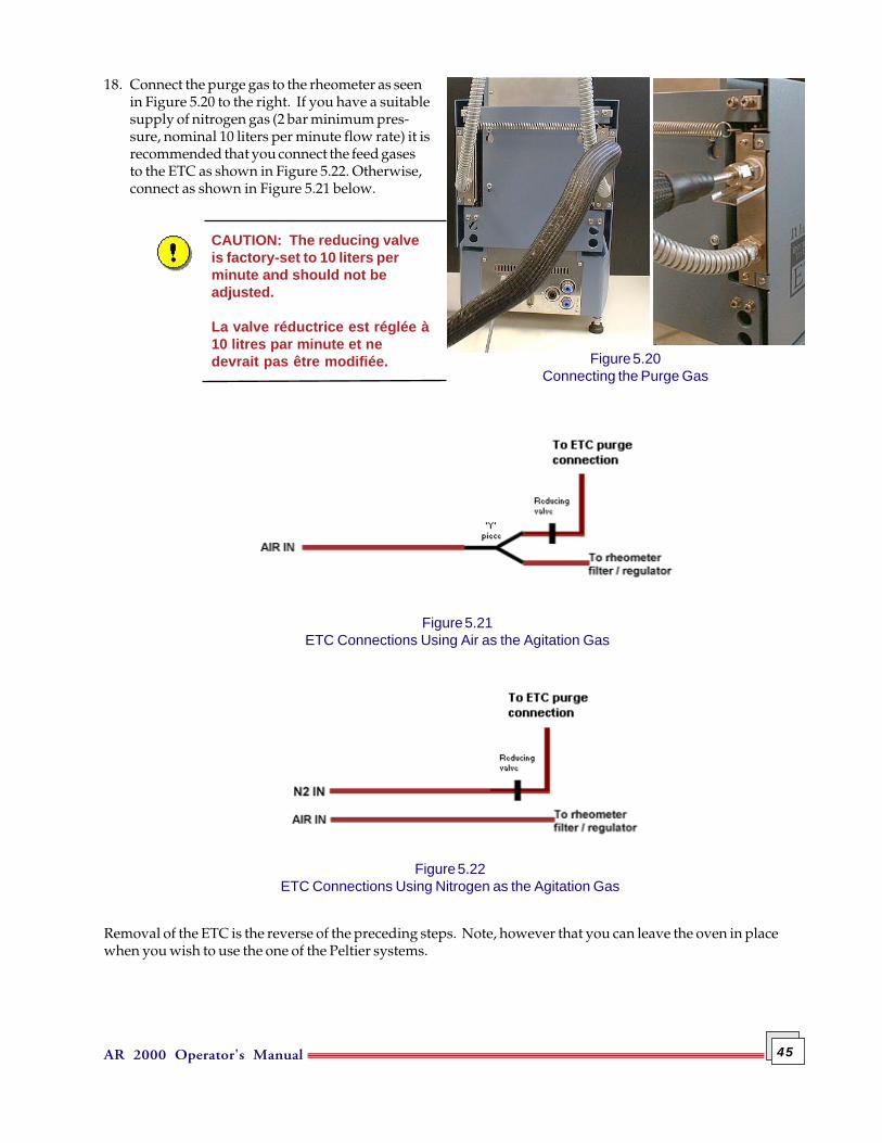
18. Connect the purge gas to the rheometer as seenin Figure 5.20 to the right. If you have a suitablesupply of nitrogen gas (2 bar minimum pres-sure, nominal 10 liters per minute flow rate) it isrecommended that you connect the feed gasesto the ETC as shown in Figure 5.22. Otherwise,connect as shown in Figure 5.21 below.
CAUTION: The reducing valveis factory-set to 10 liters perminute and should not beadjusted.
La valve réductrice est réglée à10 litres par minute et nedevrait pas être modifiée.
Removal of the ETC is the reverse of the preceding steps. Note, however that you can leave the oven in placewhen you wish to use the one of the Peltier systems.
Figure 5.21ETC Connections Using Air as the Agitation Gas
Figure 5.22ETC Connections Using Nitrogen as the Agitation Gas
AR 2000 Operator's Manual46
Installing the Low Temperature AccessoryIn order to operate the ETC at temperatures below ambient and also to facilitate rapid cooling, the (optional) lowtemperature accessory can be used. This works by supplying a controlled flow of liquid nitrogen/cold nitrogenthat is fed down the inside of the oven and evaporates off the wire wool.
Follow the installation procedure in the previous section up to step 15. Then usethe following additional steps to complete the installation (see Figure 5.24 andFigure 5.25).
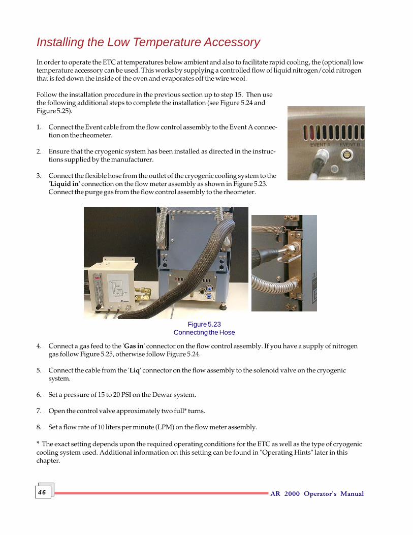
1. Connect the Event cable from the flow control assembly to the Event A connec-tion on the rheometer.
2. Ensure that the cryogenic system has been installed as directed in the instruc-tions supplied by the manufacturer.
3. Connect the flexible hose from the outlet of the cryogenic cooling system to the'Liquid in' connection on the flow meter assembly as shown in Figure 5.23.Connect the purge gas from the flow control assembly to the rheometer.
4. Connect a gas feed to the 'Gas in' connector on the flow control assembly. If you have a supply of nitrogengas follow Figure 5.25, otherwise follow Figure 5.24.
5. Connect the cable from the 'Liq' connector on the flow assembly to the solenoid valve on the cryogenicsystem.
6. Set a pressure of 15 to 20 PSI on the Dewar system.
7. Open the control valve approximately two full* turns.
8. Set a flow rate of 10 liters per minute (LPM) on the flow meter assembly.
* The exact setting depends upon the required operating conditions for the ETC as well as the type of cryogeniccooling system used. Additional information on this setting can be found in "Operating Hints" later in thischapter.
Figure 5.23Connecting the Hose
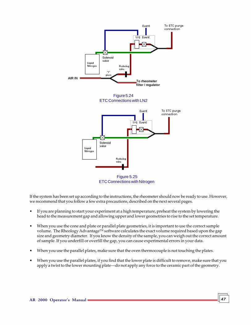
AR 2000 Operator's Manual 47
If the system has been set up according to the instructions, the rheometer should now be ready to use. However,we recommend that you follow a few extra precautions, described on the next several pages.
• If you are planning to start your experiment at a high temperature, preheat the system by lowering thehead to the measurement gap and allowing upper and lower geometries to rise to the set temperature.
• When you use the cone and plate or parallel plate geometries, it is important to use the correct samplevolume. The Rheology Advantage™ software calculates the exact volume required based upon the gapsize and geometry diameter. If you know the density of the sample, you can weigh out the correct amountof sample. If you underfill or overfill the gap, you can cause experimental errors in your data.
• When you use the parallel plates, make sure that the oven thermocouple is not touching the plates.
• When you use the parallel plates, if you find that the lower plate is difficult to remove, make sure that youapply a twist to the lower mounting plate—do not apply any force to the ceramic part of the geometry.
Figure 5.25ETC Connections with Nitrogen
Figure 5.24ETC Connections with LN2

AR 2000 Operator's Manual48
• Clean the plates immediately after your experiment with the appropriate solvent. If you are measuringhighly viscous materials, or materials that are likely to cure, unscrew the draw rod from the geometrybefore you raise the head. Stubborn materials can sometimes be removed by heating the plates to a hightemperature. The sample will bake and then crumble apart. You can also remove the plates and soak themin an appropriate solvent, or replace them with a fresh pair. It is good practice to always unscrew thedraw rod before raising the head. The two plates, together with the sample, can then be removed as asandwich unit.
• You can gently move the thermocouple (inside the oven) closer to the sample to increase performance;however, you should avoid making any sharp bends in the thermocouple sheath. Repeatedly adjusting thepositioning may damage the thermocouple and should be avoided.
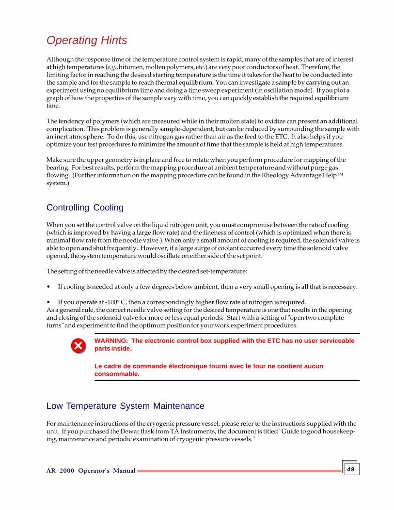
AR 2000 Operator's Manual 49
Operating HintsAlthough the response time of the temperature control system is rapid, many of the samples that are of interestat high temperatures (e.g., bitumen, molten polymers, etc.) are very poor conductors of heat. Therefore, thelimiting factor in reaching the desired starting temperature is the time it takes for the heat to be conducted intothe sample and for the sample to reach thermal equilibrium. You can investigate a sample by carrying out anexperiment using no equilibrium time and doing a time sweep experiment (in oscillation mode). If you plot agraph of how the properties of the sample vary with time, you can quickly establish the required equilibriumtime.
The tendency of polymers (which are measured while in their molten state) to oxidize can present an additionalcomplication. This problem is generally sample-dependent, but can be reduced by surrounding the sample withan inert atmosphere. To do this, use nitrogen gas rather than air as the feed to the ETC. It also helps if youoptimize your test procedures to minimize the amount of time that the sample is held at high temperatures.
Make sure the upper geometry is in place and free to rotate when you perform procedure for mapping of thebearing. For best results, perform the mapping procedure at ambient temperature and without purge gasflowing. (Further information on the mapping procedure can be found in the Rheology Advantage Help™system.)
Controlling Cooling
When you set the control valve on the liquid nitrogen unit, you must compromise between the rate of cooling(which is improved by having a large flow rate) and the fineness of control (which is optimized when there isminimal flow rate from the needle valve.) When only a small amount of cooling is required, the solenoid valve isable to open and shut frequently. However, if a large surge of coolant occurred every time the solenoid valveopened, the system temperature would oscillate on either side of the set point.
The setting of the needle valve is affected by the desired set-temperature:
• If cooling is needed at only a few degrees below ambient, then a very small opening is all that is necessary.
• If you operate at -100° C, then a correspondingly higher flow rate of nitrogen is required.As a general rule, the correct needle valve setting for the desired temperature is one that results in the openingand closing of the solenoid valve for more or less equal periods. Start with a setting of "open two completeturns" and experiment to find the optimum position for your work experiment procedures.
WARNING: The electronic control box supplied with the ETC has no user serviceableparts inside.
Le cadre de commande électronique fourni avec le four ne contient aucunconsommable.
Low Temperature System Maintenance
For maintenance instructions of the cryogenic pressure vessel, please refer to the instructions supplied with theunit. If you purchased the Dewar flask from TA Instruments, the document is titled "Guide to good housekeep-ing, maintenance and periodic examination of cryogenic pressure vessels."
AR 2000 Operator's Manual50
General Operating GuidelinesTo ensure that your temperature system operates efficiently and safely, follow these suggestions below.
DoEnsure that all operators of this equipment have been correctly trained and are aware of the safety informationcontained in this manual.
• Put this list (or a similar one) in a prominent place near the instrument.
• Read all instruction manuals supplied, as they contain useful operational hints and maintenanceinformation.
• Ensure that the gap is correctly set.
• When installing parallel plate geometries, carefully ensure that the thread is engaged squarely to avoid thepossibility of cross threading.
• Avoid any unnecessary movement of the liquid nitrogen carrying hoses when at low temperatures.Excessive movement or strain could cause the hose to crack.
Do Not• Leave the high temperature system switched on or the nitrogen tank tap open, when not in use.
• Attempt to remove a hot geometry without wearing safety gloves.
• Forcibly remove a geometry.
• Allow any object to obstruct the safety interlock sensors at the rear of the ETC housing.
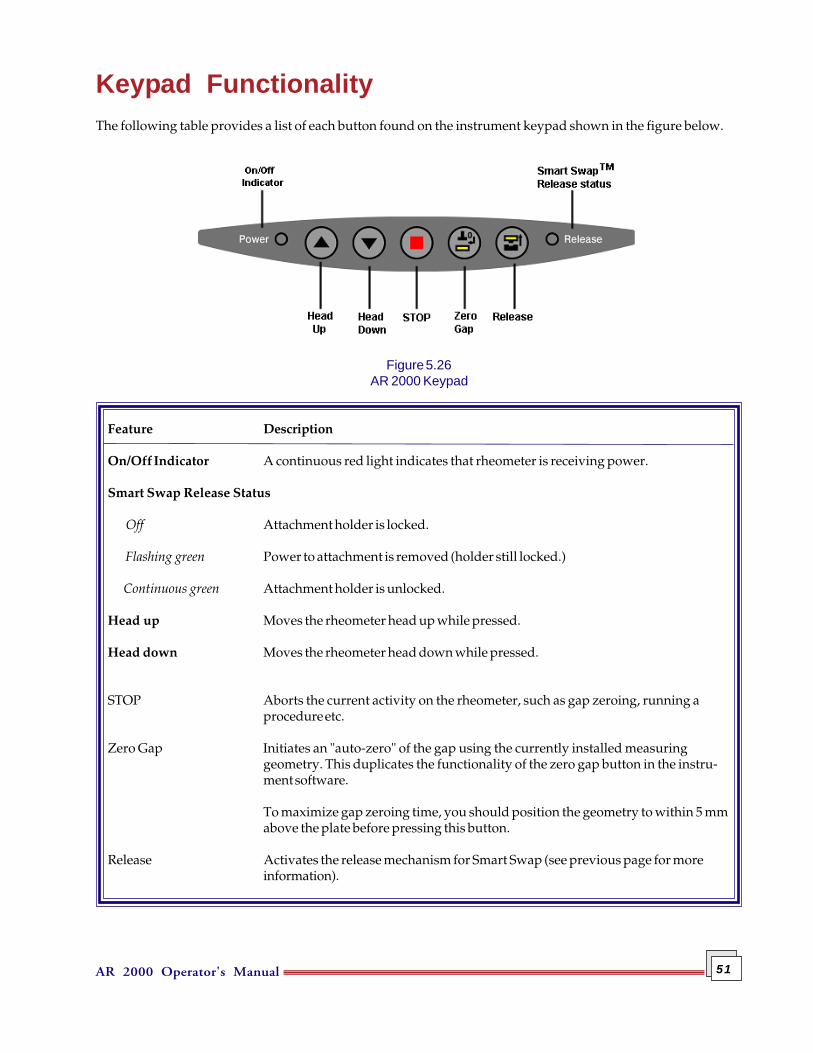
AR 2000 Operator's Manual 51
Keypad FunctionalityThe following table provides a list of each button found on the instrument keypad shown in the figure below.
Figure 5.26AR 2000 Keypad
Feature Description
On/Off Indicator A continuous red light indicates that rheometer is receiving power.
Smart Swap Release Status
Off Attachment holder is locked.
Flashing green Power to attachment is removed (holder still locked.)
Continuous green Attachment holder is unlocked.
Head up Moves the rheometer head up while pressed.
Head down Moves the rheometer head down while pressed.
STOP Aborts the current activity on the rheometer, such as gap zeroing, running aprocedure etc.
Zero Gap Initiates an "auto-zero" of the gap using the currently installed measuringgeometry. This duplicates the functionality of the zero gap button in the instru-ment software.
To maximize gap zeroing time, you should position the geometry to within 5 mmabove the plate before pressing this button.
Release Activates the release mechanism for Smart Swap (see previous page for moreinformation).

AR 2000 Operator's Manual52
Levelling the RheometerOptimum performance depends upon the instrument being level and in a sturdy position to avoid the possibil-ity of rocking. To check and see whether your instrument is level, simply place a bubble spirit level on the lowertemperature module plate.
If the instrument is not level, screw the adjustable feet (located at each corner of the instrument) either in or out,as necessary. Check the spirit level after each adjustment. Once you have the instrument levelled correctly,press each corner of the instrument to check that all four feet are in contact with the laboratory bench. Anymovement caused by pressing should be rectified by adjusting the feet, and then rechecking the level of the plate.
If the spirit level is the circular type, it should be placed in the middle of the plate. If the spirit level is the bartype, place it along a diameter of the plate. Check the level by placing it along another diameter of the plate at90° to the first position.
Checking Your SystemAfter installation has been completed, start the instrument to check to make sure everything is working and thatall parts of the system are communicating with each other. Use the following steps to check your system:
1. Turn on the air supply to the instrument.
2. Turn on the water supply to the instrument.
3. Remove the air-bearing clamp.
4. Turn on all electrical parts of the system (rheometer, PC, etc.). A system check will be initiated as shown bythe LCD on the electronics control box.
5. Start the rheology software.
6. Select the Instrument Status screen in the software.
7. If everything is installed correctly, the instrument will display continually updating figures.
8. Lower the head using the buttons in the software. If the installation is OK, the head will operate.
9. Input a temperature slightly different to that displayed. If the installation is OK, the temperature willchange to the new one you have just input.
10. Raise the head.
If all of these actions result in the correct response, you can be confident that you have installed the systemcorrectly and it is ready for use. If you have problems, please contact your local TA Instruments office or theirappointed agent.
AR 2000 Operator's Manual 53
Calibrating the RheometerStrictly speaking, you cannot calibrate your rheometer yourself. You can check that the instrument is function-ing properly by measuring the viscosity of a certified standard Newtonian oil. (Cannon S600 oil, which has anominal viscosity of 1.4 Pas at 25°C, or PTB 1000A, which has a nominal viscosity of 1 Pas at 20.0°C.) If you geta greater than 4% error in the reading, there is a possibility that your rheometer needs some attention from a TAInstruments Service Engineer.
Carry out the following experiment:
1. Attach a 60 mm 2° stainless steel cone to the rheometer. (This is the preferred geometry, if you do not haveone use the largest cone that you do have.)
2. Set the zero gap and measurement system gap in the usual way.
3. Carefully load the sample ensuring correct filling.
4. Carry out a 4-minute flow test, continuous ramp, controlled stress range 0 to 88.0 Pa at 20°C.
5. Determine the Newtonian viscosity. If this value is more than 4% different from the certified value, repeatthe experiment. If there is still an error, call your local TA Instruments office for advice.
There are several sources of operator error that can give erroneous answers. This does not necessarily mean thatyour instrument is not working properly. These include errors in setting the gap, incorrect temperatures used,or over- or under-filling of the gap. This calibration check needs to be carried out monthly.
Shut-Down ProcedureWhen you are ready to turn the instrument off, it is important that you follow the steps listed below in thecorrect order.
1. Raise the head and remove the measuring geometry.
2. Exit the software package that you are currently running.
3. Turn off the rheometer and the computer.
4. Replace the air-bearing clamp.
5. Turn off the water supply to the instrument.
6. Turn off the air supply to the instrument.
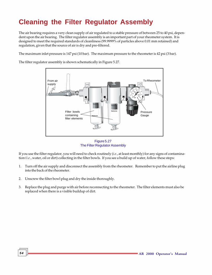
AR 2000 Operator's Manual54
Cleaning the Filter Regulator AssemblyThe air bearing requires a very clean supply of air regulated to a stable pressure of between 25 to 40 psi, depen-dent upon the air bearing. The filter regulator assembly is an important part of your rheometer system. It isdesigned to meet the required standards of cleanliness (99.9999% of particles above 0.01 mm retained) andregulation, given that the source of air is dry and pre-filtered.
The maximum inlet pressure is 147 psi (10 bar). The maximum pressure to the rheometer is 42 psi (3 bar).
The filter regulator assembly is shown schematically in Figure 5.27.
Figure 5.27The Filter Regulator Assembly
If you use the filter regulator, you will need to check routinely (i.e., at least monthly) for any signs of contamina-tion (i.e., water, oil or dirt) collecting in the filter bowls. If you see a build up of water, follow these steps:
1. Turn off the air supply and disconnect the assembly from the rheometer. Remember to put the airline pluginto the back of the rheometer.
2. Unscrew the filter bowl plug and dry the inside thoroughly.
3. Replace the plug and purge with air before reconnecting to the rheometer. The filter elements must also bereplaced when there is a visible buildup of dirt.
From airsupply
Filter bowlscontainingfilter elements
PressureGauge
To Rheometer
AR 2000 Operator's Manual 55
Chapter 6Measuring Systems
OverviewThis chapter describes the geometries currently available from TA Instruments and provides guidelines tochoose the optimum geometry (or measuring system) for each application. A complete geometry catalog isavailable which describes in detail each geometry and typical applications. Contact your local TA Instrumentsoffice or their appointed agent for further details. Some theoretical considerations are given that will provideguidance and help you maximize the use of the AR Rheometers.
TA Instruments offers a range of geometries. The geometries are divided into the following groups, each with arange of sizes available:
• Cone and plate• Parallel plate• Concentric cylinders.
The following pages describe the types of geometries and provide details on how to attach the geometry to therheometer.
General DescriptionThe measuring system is defined as those parts that are in direct contact with the sample or material.
A measuring system consists of two parts:
• One is the fixed member (or Stator), for example, the Peltier plate.
• The second part (the geometry) is attached to the driving motor spindle, where it is locked in positionusing the draw rod. The draw rod is detachable and passes through the centre hole bored in the spindle.The geometry constitutes the moving member of the system (the Rotor).
Geometry MaterialsGeometries are usually constructed from stainless steel, aluminium, or acrylic (other materials can be suppliedupon request). The rotor should ideally be as light as possible to minimize inherent inertia effects. It shouldalso be chemically compatible with the test sample in order to avoid corrosion problems.
Stainless SteelStainless steel is relatively heavy, but it has a low coefficient of thermal expansion. It is compatible with mosttest materials and is robust enough to withstand heavy use, even if you are a less experienced operator.
AluminiumAluminium has a higher thermal coefficient of expansion and is limited because of its chemical compatibility.As it is lighter, inertial effects are not as great.
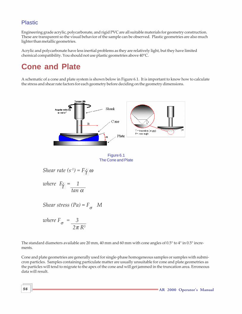
AR 2000 Operator's Manual56
PlasticEngineering grade acrylic, polycarbonate, and rigid PVC are all suitable materials for geometry construction.These are transparent so the visual behavior of the sample can be observed. Plastic geometries are also muchlighter than metallic geometries.
Acrylic and polycarbonate have less inertial problems as they are relatively light, but they have limitedchemical compatibility. You should not use plastic geometries above 40°C.
Cone and PlateA schematic of a cone and plate system is shown below in Figure 6.1. It is important to know how to calculatethe stress and shear rate factors for each geometry before deciding on the geometry dimensions.
Figure 6.1The Cone and Plate
Shear rate (s-1) = F ω
where F = 1tan α
Shear stress (Pa) = Fσ M
where Fσ = 3 2π R3
The standard diameters available are 20 mm, 40 mm and 60 mm with cone angles of 0.5° to 4° in 0.5° incre-ments.
Cone and plate geometries are generally used for single-phase homogeneous samples or samples with submi-cron particles. Samples containing particulate matter are usually unsuitable for cone and plate geometries asthe particles will tend to migrate to the apex of the cone and will get jammed in the truncation area. Erroneousdata will result.
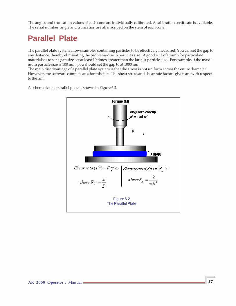
AR 2000 Operator's Manual 57
The angles and truncation values of each cone are individually calibrated. A calibration certificate is available.The serial number, angle and truncation are all inscribed on the stem of each cone.
Parallel PlateThe parallel plate system allows samples containing particles to be effectively measured. You can set the gap toany distance, thereby eliminating the problems due to particles size. A good rule of thumb for particulatematerials is to set a gap size set at least 10 times greater than the largest particle size. For example, if the maxi-mum particle size is 100 mm, you should set the gap to at 1000 mm.The main disadvantage of a parallel plate system is that the stress is not uniform across the entire diameter.However, the software compensates for this fact. The shear stress and shear rate factors given are with respectto the rim.
A schematic of a parallel plate is shown in Figure 6.2.
Figure 6.2The Parallel Plate
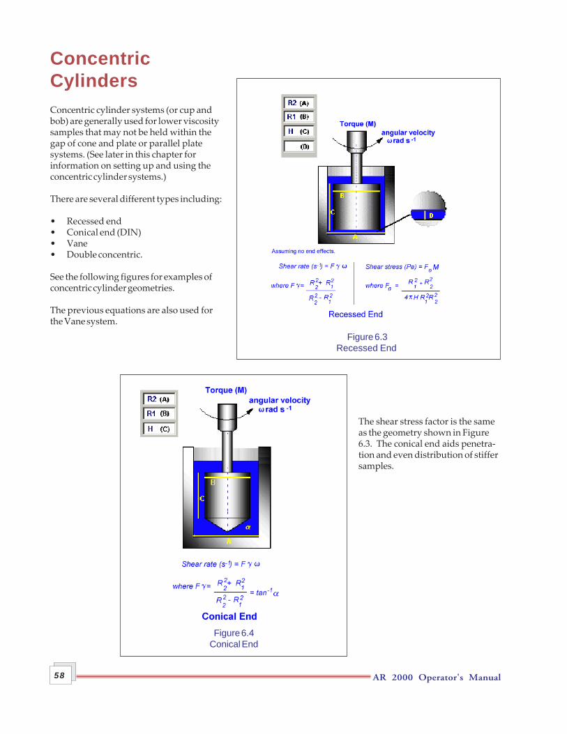
AR 2000 Operator's Manual58
ConcentricCylindersConcentric cylinder systems (or cup andbob) are generally used for lower viscositysamples that may not be held within thegap of cone and plate or parallel platesystems. (See later in this chapter forinformation on setting up and using theconcentric cylinder systems.)
There are several different types including:
• Recessed end• Conical end (DIN)• Vane• Double concentric.
See the following figures for examples ofconcentric cylinder geometries.
The previous equations are also used forthe Vane system.
The shear stress factor is the sameas the geometry shown in Figure6.3. The conical end aids penetra-tion and even distribution of stiffersamples.
Figure 6.4Conical End
Figure 6.3Recessed End

AR 2000 Operator's Manual 59
The ratio R1:R2 = R3:R4. The shearrate is then calculated as in Figure6.3 using R3 and R4.
Using theStress and Shear Rate FactorsThe TA Instruments operating system software calculates the stress and shear rate factors, which are used bythe software in all subsequent calculations.
However, there may be occasions when you will need to enter these factors manually. If you do, follow thesequence given below:
1. Multiply the angular velocity (ω) by the shear rate factor ( F ) to obtain the shear rate (s-1).
2. Multiply the angular displacement by the same factor to obtain the strain (dimensionless).
3. Multiply the torque (T) (µNm) by the shear stress factor ( Fσ) to obtain the shear stress (Pa).
Figure 6.5Double Concentric
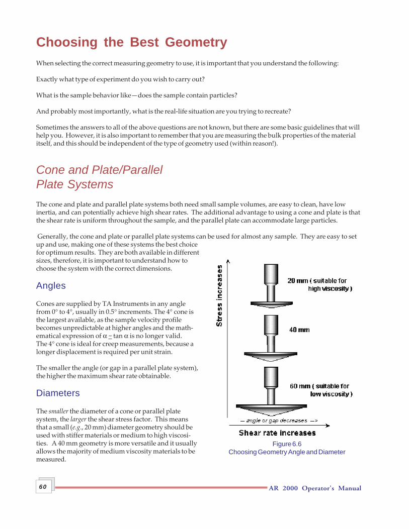
AR 2000 Operator's Manual60
Choosing the Best GeometryWhen selecting the correct measuring geometry to use, it is important that you understand the following:
Exactly what type of experiment do you wish to carry out?
What is the sample behavior like—does the sample contain particles?
And probably most importantly, what is the real-life situation are you trying to recreate?
Sometimes the answers to all of the above questions are not known, but there are some basic guidelines that willhelp you. However, it is also important to remember that you are measuring the bulk properties of the materialitself, and this should be independent of the type of geometry used (within reason!).
Cone and Plate/ParallelPlate SystemsThe cone and plate and parallel plate systems both need small sample volumes, are easy to clean, have lowinertia, and can potentially achieve high shear rates. The additional advantage to using a cone and plate is thatthe shear rate is uniform throughout the sample, and the parallel plate can accommodate large particles.
Generally, the cone and plate or parallel plate systems can be used for almost any sample. They are easy to setup and use, making one of these systems the best choicefor optimum results. They are both available in differentsizes, therefore, it is important to understand how tochoose the system with the correct dimensions.
Angles
Cones are supplied by TA Instruments in any anglefrom 0° to 4°, usually in 0.5° increments. The 4° cone isthe largest available, as the sample velocity profilebecomes unpredictable at higher angles and the math-ematical expression of α ~ tan α is no longer valid.The 4° cone is ideal for creep measurements, because alonger displacement is required per unit strain.
The smaller the angle (or gap in a parallel plate system),the higher the maximum shear rate obtainable.
Diameters
The smaller the diameter of a cone or parallel platesystem, the larger the shear stress factor. This meansthat a small (e.g., 20 mm) diameter geometry should beused with stiffer materials or medium to high viscosi-ties. A 40 mm geometry is more versatile and it usuallyallows the majority of medium viscosity materials to bemeasured.
Figure 6.6Choosing Geometry Angle and Diameter

AR 2000 Operator's Manual 61
A large diameter geometry (e.g., 60 mm) is more sensitive to stress changes and is used to measure low viscositysamples.
Be sure to load the sample correctly and be careful not to under or overfill the geometry. If this occurs, it wouldeffectively change the diameters of the cones and, hence, adversely affect the shear stress factors.
Figure 6.6 summarizes the information given above on the choice of angle (or gap) and diameter.
Material
Stainless steel is relatively heavy, has a low coefficient of thermal expansion, is compatible with most samples,and is very robust.
Aluminium geometries are lighter than steel, but have a larger coefficient of thermal expansion. They will go totemperatures greater than 40°C, but are still heavier than acrylic.
Acrylic geometries are very light and are, therefore, most suitable to use with low viscosity samples. However,you should not use acrylic geometries above 40°C.
See the beginning of this chapter for more details on materials.
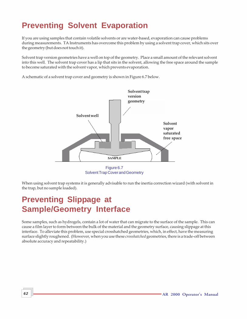
AR 2000 Operator's Manual62
Preventing Solvent EvaporationIf you are using samples that contain volatile solvents or are water-based, evaporation can cause problemsduring measurements. TA Instruments has overcome this problem by using a solvent trap cover, which sits overthe geometry (but does not touch it).
Solvent trap version geometries have a well on top of the geometry. Place a small amount of the relevant solventinto this well. The solvent trap cover has a lip that sits in the solvent, allowing the free space around the sampleto become saturated with the solvent vapor, which prevents evaporation.
A schematic of a solvent trap cover and geometry is shown in Figure 6.7 below.
When using solvent trap systems it is generally advisable to run the inertia correction wizard (with solvent inthe trap, but no sample loaded).
Preventing Slippage atSample/Geometry InterfaceSome samples, such as hydrogels, contain a lot of water that can migrate to the surface of the sample. This cancause a film layer to form between the bulk of the material and the geometry surface, causing slippage at thisinterface. To alleviate this problem, use special crosshatched geometries, which, in effect, have the measuringsurface slightly roughened. (However, when you use these crosshatched geometries, there is a trade-off betweenabsolute accuracy and repeatability.)
Solvent well
Solvent trapversiongeometry
Solventvaporsaturatedfree space
Figure 6.7Solvent Trap Cover and Geometry
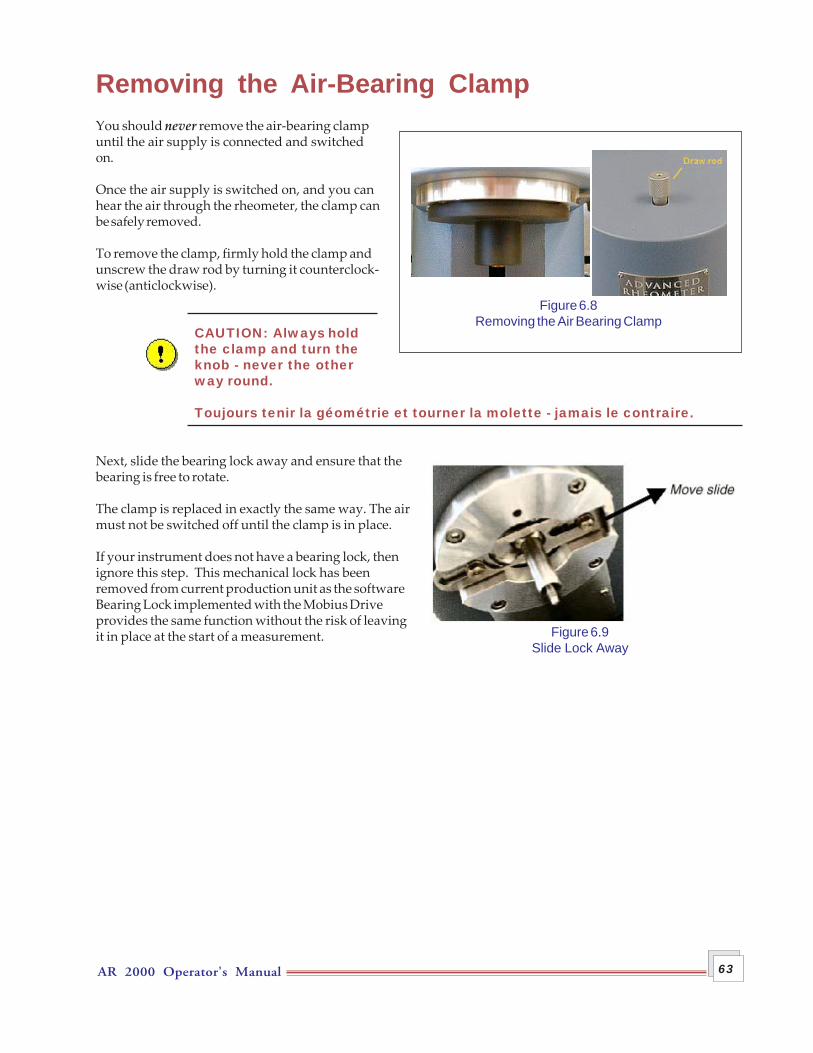
AR 2000 Operator's Manual 63
Removing the Air-Bearing ClampYou should never remove the air-bearing clampuntil the air supply is connected and switchedon.
Once the air supply is switched on, and you canhear the air through the rheometer, the clamp canbe safely removed.
To remove the clamp, firmly hold the clamp andunscrew the draw rod by turning it counterclock-wise (anticlockwise).
CAUTION: Always holdthe clamp and turn theknob - never the otherway round.
Toujours tenir la géométrie et tourner la molette - jamais le contraire.
Next, slide the bearing lock away and ensure that thebearing is free to rotate.
The clamp is replaced in exactly the same way. The airmust not be switched off until the clamp is in place.
If your instrument does not have a bearing lock, thenignore this step. This mechanical lock has beenremoved from current production unit as the softwareBearing Lock implemented with the Mobius Driveprovides the same function without the risk of leavingit in place at the start of a measurement.
Figure 6.8Removing the Air Bearing Clamp
Figure 6.9Slide Lock Away
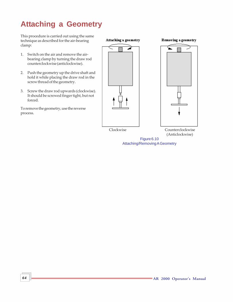
AR 2000 Operator's Manual64
Clockwise Counterclockwise (Anticlockwise)
Figure 6.10Attaching/Removing A Geometry
Attaching a GeometryThis procedure is carried out using the sametechnique as described for the air-bearingclamp:
1. Switch on the air and remove the air-bearing clamp by turning the draw rodcounterclockwise (anticlockwise).
2. Push the geometry up the drive shaft andhold it while placing the draw rod in thescrew thread of the geometry.
3. Screw the draw rod upwards (clockwise).It should be screwed finger tight, but notforced.
To remove the geometry, use the reverseprocess.
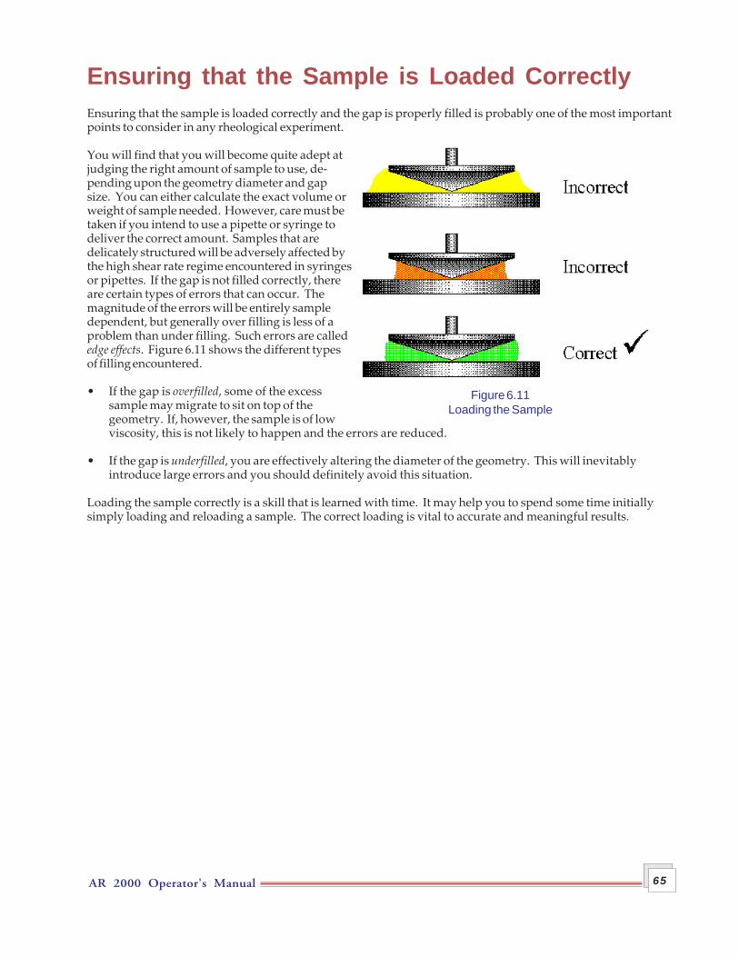
AR 2000 Operator's Manual 65
Figure 6.11Loading the Sample
Ensuring that the Sample is Loaded CorrectlyEnsuring that the sample is loaded correctly and the gap is properly filled is probably one of the most importantpoints to consider in any rheological experiment.
You will find that you will become quite adept atjudging the right amount of sample to use, de-pending upon the geometry diameter and gapsize. You can either calculate the exact volume orweight of sample needed. However, care must betaken if you intend to use a pipette or syringe todeliver the correct amount. Samples that aredelicately structured will be adversely affected bythe high shear rate regime encountered in syringesor pipettes. If the gap is not filled correctly, thereare certain types of errors that can occur. Themagnitude of the errors will be entirely sampledependent, but generally over filling is less of aproblem than under filling. Such errors are callededge effects. Figure 6.11 shows the different typesof filling encountered.
• If the gap is overfilled, some of the excesssample may migrate to sit on top of thegeometry. If, however, the sample is of lowviscosity, this is not likely to happen and the errors are reduced.
• If the gap is underfilled, you are effectively altering the diameter of the geometry. This will inevitablyintroduce large errors and you should definitely avoid this situation.
Loading the sample correctly is a skill that is learned with time. It may help you to spend some time initiallysimply loading and reloading a sample. The correct loading is vital to accurate and meaningful results.

AR 2000 Operator's Manual66
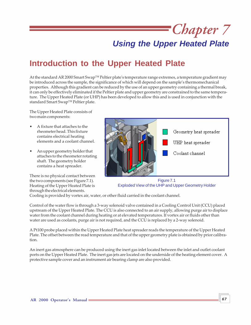
AR 2000 Operator's Manual 67
Chapter 7Using the Upper Heated Plate
Introduction to the Upper Heated PlateAt the standard AR 2000 Smart Swap™ Peltier plate's temperature range extremes, a temperature gradient maybe introduced across the sample, the significance of which will depend on the sample’s thermomechanicalproperties. Although this gradient can be reduced by the use of an upper geometry containing a thermal break,it can only be effectively eliminated if the Peltier plate and upper geometry are constrained to the same tempera-ture. The Upper Heated Plate (or UHP) has been developed to allow this and is used in conjunction with thestandard Smart Swap™ Peltier plate.
The Upper Heated Plate consists oftwo main components:
• A fixture that attaches to therheometer head. This fixturecontains electrical heatingelements and a coolant channel.
• An upper geometry holder thatattaches to the rheometer rotatingshaft. The geometry holdercontains a heat spreader.
There is no physical contact betweenthe two components (see Figure 7.1).Heating of the Upper Heated Plate isthrough the electrical elements.Cooling is provided by vortex air, water, or other fluid carried in the coolant channel.
Control of the water flow is through a 3-way solenoid valve contained in a Cooling Control Unit (CCU) placedupstream of the Upper Heated Plate. The CCU is also connected to an air supply, allowing purge air to displacewater from the coolant channel during heating or at elevated temperatures. If vortex air or fluids other thanwater are used as coolants, purge air is not required, and the CCU is replaced by a 2-way solenoid.
A Pt100 probe placed within the Upper Heated Plate heat spreader reads the temperature of the Upper HeatedPlate. The offset between the read temperature and that of the upper geometry plate is obtained by prior calibra-tion.
An inert gas atmosphere can be produced using the inert gas inlet located between the inlet and outlet coolantports on the Upper Heated Plate. The inert gas jets are located on the underside of the heating element cover. Aprotective sample cover and an instrument air bearing clamp are also provided.
Figure 7.1Exploded View of the UHP and Upper Geometry Holder
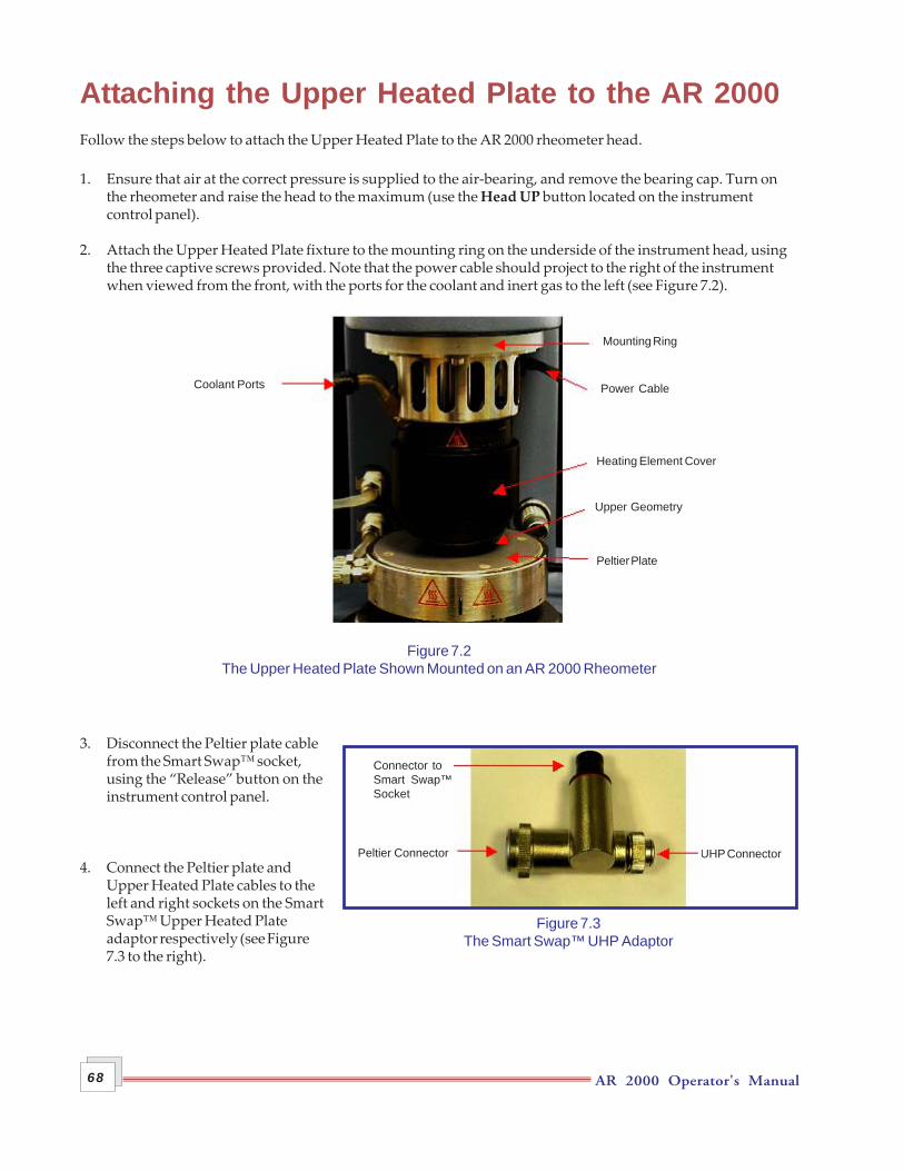
AR 2000 Operator's Manual68
Attaching the Upper Heated Plate to the AR 2000Follow the steps below to attach the Upper Heated Plate to the AR 2000 rheometer head.
1. Ensure that air at the correct pressure is supplied to the air-bearing, and remove the bearing cap. Turn onthe rheometer and raise the head to the maximum (use the Head UP button located on the instrumentcontrol panel).
2. Attach the Upper Heated Plate fixture to the mounting ring on the underside of the instrument head, usingthe three captive screws provided. Note that the power cable should project to the right of the instrumentwhen viewed from the front, with the ports for the coolant and inert gas to the left (see Figure 7.2).
Figure 7.2The Upper Heated Plate Shown Mounted on an AR 2000 Rheometer
3. Disconnect the Peltier plate cablefrom the Smart Swap™ socket,using the “Release” button on theinstrument control panel.
4. Connect the Peltier plate andUpper Heated Plate cables to theleft and right sockets on the SmartSwap™ Upper Heated Plateadaptor respectively (see Figure7.3 to the right).
Power Cable
Mounting Ring
Peltier Plate
Heating Element Cover
Upper Geometry
Coolant Ports
Figure 7.3The Smart Swap™ UHP Adaptor
Connector toSmart Swap™Socket
Peltier Connector UHP Connector
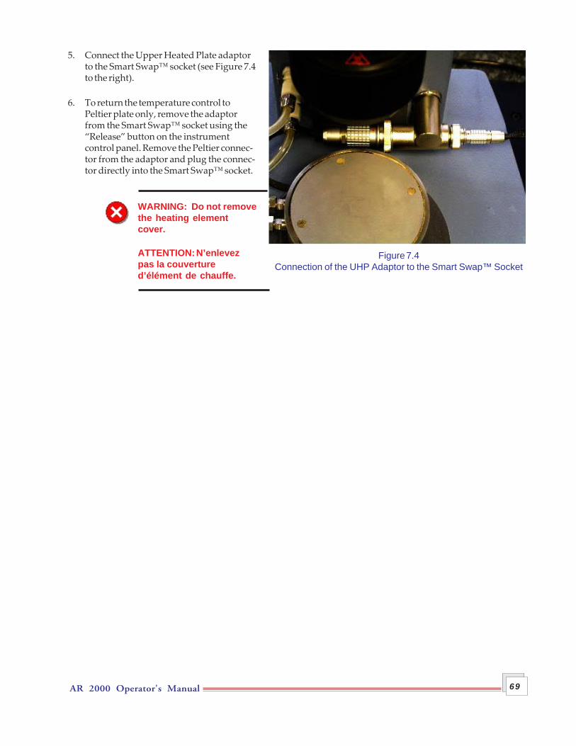
AR 2000 Operator's Manual 69
5. Connect the Upper Heated Plate adaptorto the Smart Swap™ socket (see Figure 7.4to the right).
6. To return the temperature control toPeltier plate only, remove the adaptorfrom the Smart Swap™ socket using the“Release” button on the instrumentcontrol panel. Remove the Peltier connec-tor from the adaptor and plug the connec-tor directly into the Smart Swap™ socket.
WARNING: Do not removethe heating elementcover.
ATTENTION: N’enlevezpas la couvertured’élément de chauffe.
Figure 7.4Connection of the UHP Adaptor to the Smart Swap™ Socket
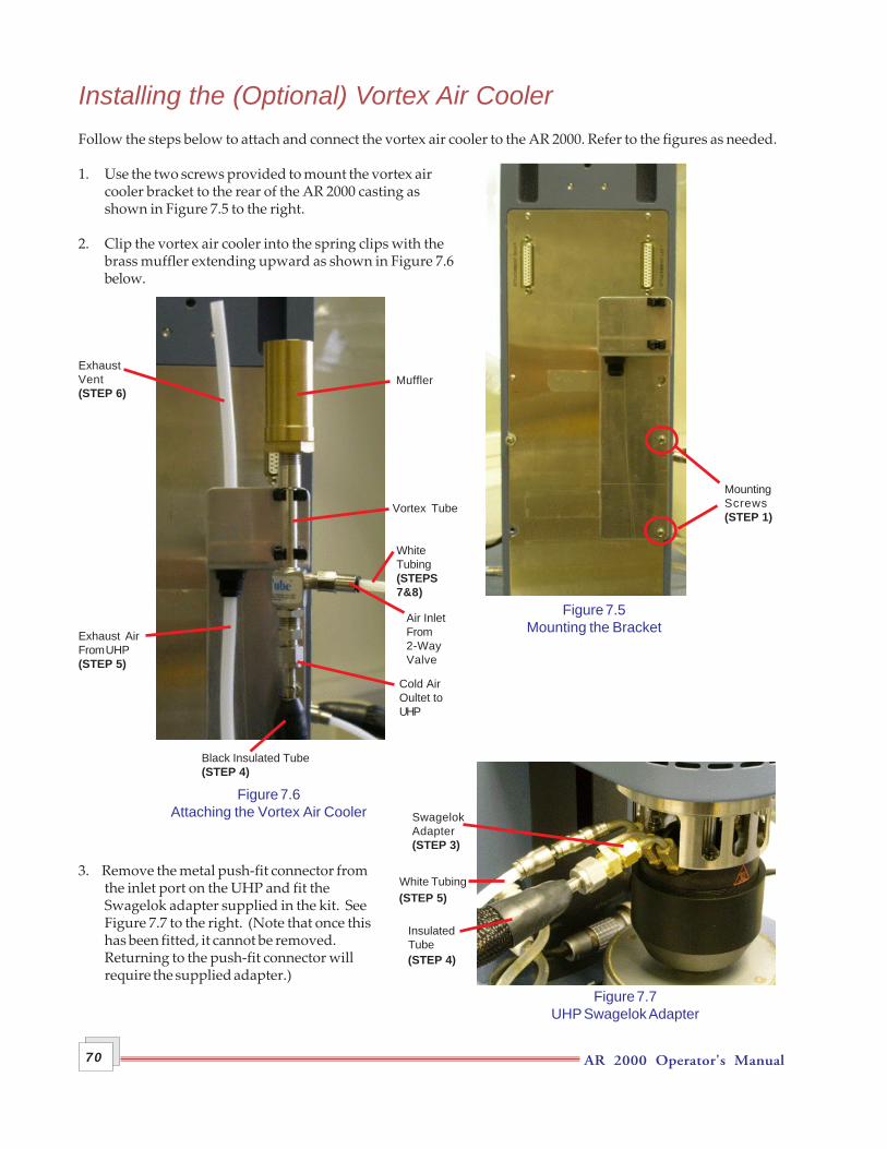
AR 2000 Operator's Manual70
Installing the (Optional) Vortex Air CoolerFollow the steps below to attach and connect the vortex air cooler to the AR 2000. Refer to the figures as needed.
1. Use the two screws provided to mount the vortex aircooler bracket to the rear of the AR 2000 casting asshown in Figure 7.5 to the right.
2. Clip the vortex air cooler into the spring clips with thebrass muffler extending upward as shown in Figure 7.6below.
3. Remove the metal push-fit connector fromthe inlet port on the UHP and fit theSwagelok adapter supplied in the kit. SeeFigure 7.7 to the right. (Note that once thishas been fitted, it cannot be removed.Returning to the push-fit connector willrequire the supplied adapter.)
Figure 7.5Mounting the Bracket
MountingScrews(STEP 1)
Air InletFrom2-WayValve
Figure 7.6Attaching the Vortex Air Cooler
ExhaustVent(STEP 6)
Exhaust AirFrom UHP(STEP 5)
Muffler
Vortex Tube
Cold AirOultet toUHP
WhiteTubing(STEPS7&8)
Black Insulated Tube(STEP 4)
Figure 7.7UHP Swagelok Adapter
InsulatedTube
SwagelokAdapter(STEP 3)
(STEP 4)
(STEP 5)White Tubing
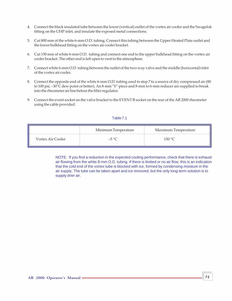
AR 2000 Operator's Manual 71
4. Connect the black insulated tube between the lower (vertical) outlet of the vortex air cooler and the Swagelokfitting on the UHP inlet, and insulate the exposed metal connections.
5. Cut 800 mm of the white 6-mm O.D. tubing. Connect this tubing between the Upper Heated Plate outlet andthe lower bulkhead fitting on the vortex air cooler bracket.
6. Cut 150 mm of white 6-mm O.D. tubing and connect one end to the upper bulkhead fitting on the vortex aircooler bracket. The other end is left open to vent to the atmosphere.
7. Connect white 6-mm O.D. tubing between the outlet of the two-way valve and the middle (horizontal) inletof the vortex air cooler.
8. Connect the opposite end of the white 6-mm O.D. tubing used in step 7 to a source of dry compressed air (80to 100 psi, –30°C dew point or better). An 8-mm "Y"-piece and 8-mm to 6-mm reducer are supplied to breakinto the rheometer air line before the filter regulator.
9. Connect the event socket on the valve bracket to the EVENT B socket on the rear of the AR 2000 rheometerusing the cable provided.
Table 7.1
Minimum Temperature Maximum Temperature
Vortex Air Cooler –5 °C 150 °C
NOTE: If you find a reduction in the expected cooling performance, check that there is exhaustair flowing from the white 8-mm O.D. tubing. If there is limited or no air flow, this is an indicationthat the cold end of the vortex tube is blocked with ice, formed by condensing moisture in theair supply. The tube can be taken apart and ice removed, but the only long-term solution is tosupply drier air.
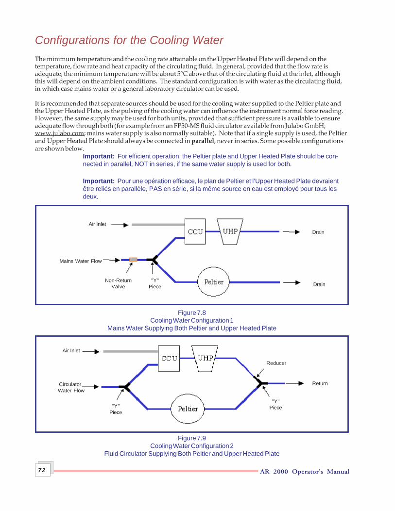
AR 2000 Operator's Manual72
Configurations for the Cooling WaterThe minimum temperature and the cooling rate attainable on the Upper Heated Plate will depend on thetemperature, flow rate and heat capacity of the circulating fluid. In general, provided that the flow rate isadequate, the minimum temperature will be about 5°C above that of the circulating fluid at the inlet, althoughthis will depend on the ambient conditions. The standard configuration is with water as the circulating fluid,in which case mains water or a general laboratory circulator can be used.
It is recommended that separate sources should be used for the cooling water supplied to the Peltier plate andthe Upper Heated Plate, as the pulsing of the cooling water can influence the instrument normal force reading.However, the same supply may be used for both units, provided that sufficient pressure is available to ensureadequate flow through both (for example from an FP50-MS fluid circulator available from Julabo GmbH,www.julabo.com; mains water supply is also normally suitable). Note that if a single supply is used, the Peltierand Upper Heated Plate should always be connected in parallel, never in series. Some possible configurationsare shown below.
Important: For efficient operation, the Peltier plate and Upper Heated Plate should be con-nected in parallel, NOT in series, if the same water supply is used for both.
Important: Pour une opération efficace, le plan de Peltier et l’Upper Heated Plate devraientêtre reliés en parallèle, PAS en série, si la même source en eau est employé pour tous lesdeux.
Figure 7.8Cooling Water Configuration 1
Mains Water Supplying Both Peltier and Upper Heated Plate
Figure 7.9Cooling Water Configuration 2
Fluid Circulator Supplying Both Peltier and Upper Heated Plate
Air Inlet
Mains Water Flow
Non-ReturnValve
"Y"Piece Drain
Air Inlet
Circulator Water Flow
Return
"Y"Piece
Drain
"Y"Piece
Reducer
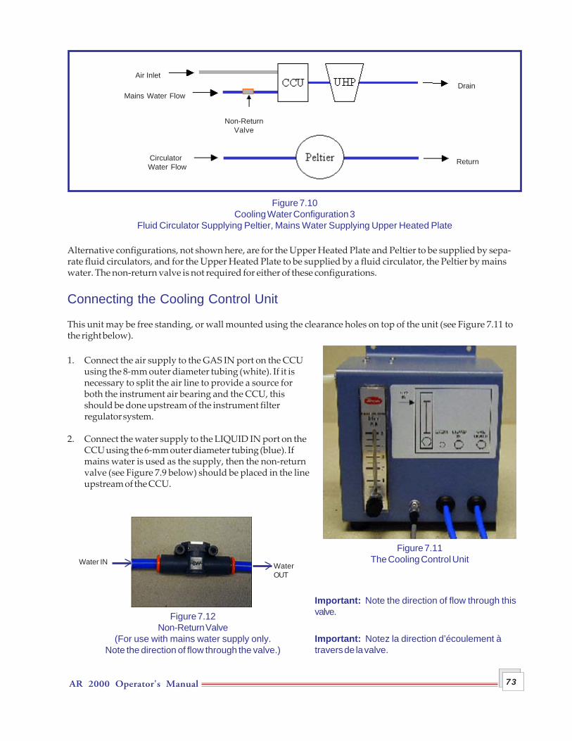
AR 2000 Operator's Manual 73
Figure 7.10Cooling Water Configuration 3
Fluid Circulator Supplying Peltier, Mains Water Supplying Upper Heated Plate
Alternative configurations, not shown here, are for the Upper Heated Plate and Peltier to be supplied by sepa-rate fluid circulators, and for the Upper Heated Plate to be supplied by a fluid circulator, the Peltier by mainswater. The non-return valve is not required for either of these configurations.
Connecting the Cooling Control Unit
This unit may be free standing, or wall mounted using the clearance holes on top of the unit (see Figure 7.11 tothe right below).
1. Connect the air supply to the GAS IN port on the CCUusing the 8-mm outer diameter tubing (white). If it isnecessary to split the air line to provide a source forboth the instrument air bearing and the CCU, thisshould be done upstream of the instrument filterregulator system.
2. Connect the water supply to the LIQUID IN port on theCCU using the 6-mm outer diameter tubing (blue). Ifmains water is used as the supply, then the non-returnvalve (see Figure 7.9 below) should be placed in the lineupstream of the CCU.
Important: Note the direction of flow through thisvalve.
Important: Notez la direction d’écoulement àtravers de la valve.
Figure 7.11The Cooling Control Unit
Figure 7.12Non-Return Valve
(For use with mains water supply only.Note the direction of flow through the valve.)
Water IN WaterOUT
Air Inlet
Mains Water Flow
Non-ReturnValve
Circulator Water Flow
Return
Drain
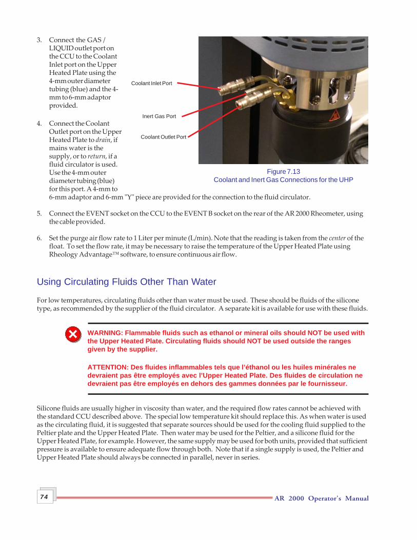
AR 2000 Operator's Manual74
3. Connect the GAS /LIQUID outlet port onthe CCU to the CoolantInlet port on the UpperHeated Plate using the4-mm outer diametertubing (blue) and the 4-mm to 6-mm adaptorprovided.
4. Connect the CoolantOutlet port on the UpperHeated Plate to drain, ifmains water is thesupply, or to return, if afluid circulator is used.Use the 4-mm outerdiameter tubing (blue)for this port. A 4-mm to6-mm adaptor and 6-mm "Y" piece are provided for the connection to the fluid circulator.
5. Connect the EVENT socket on the CCU to the EVENT B socket on the rear of the AR 2000 Rheometer, usingthe cable provided.
6. Set the purge air flow rate to 1 Liter per minute (L/min). Note that the reading is taken from the center of thefloat. To set the flow rate, it may be necessary to raise the temperature of the Upper Heated Plate usingRheology Advantage™ software, to ensure continuous air flow.
Using Circulating Fluids Other Than Water
For low temperatures, circulating fluids other than water must be used. These should be fluids of the siliconetype, as recommended by the supplier of the fluid circulator. A separate kit is available for use with these fluids.
WARNING: Flammable fluids such as ethanol or mineral oils should NOT be used withthe Upper Heated Plate. Circulating fluids should NOT be used outside the rangesgiven by the supplier.
ATTENTION: Des fluides inflammables tels que l’éthanol ou les huiles minérales nedevraient pas être employés avec l’Upper Heated Plate. Des fluides de circulation nedevraient pas être employés en dehors des gammes données par le fournisseur.
Silicone fluids are usually higher in viscosity than water, and the required flow rates cannot be achieved withthe standard CCU described above. The special low temperature kit should replace this. As when water is usedas the circulating fluid, it is suggested that separate sources should be used for the cooling fluid supplied to thePeltier plate and the Upper Heated Plate. Then water may be used for the Peltier, and a silicone fluid for theUpper Heated Plate, for example. However, the same supply may be used for both units, provided that sufficientpressure is available to ensure adequate flow through both. Note that if a single supply is used, the Peltier andUpper Heated Plate should always be connected in parallel, never in series.
Figure 7.13Coolant and Inert Gas Connections for the UHP
Coolant Inlet Port
Inert Gas Port
Coolant Outlet Port
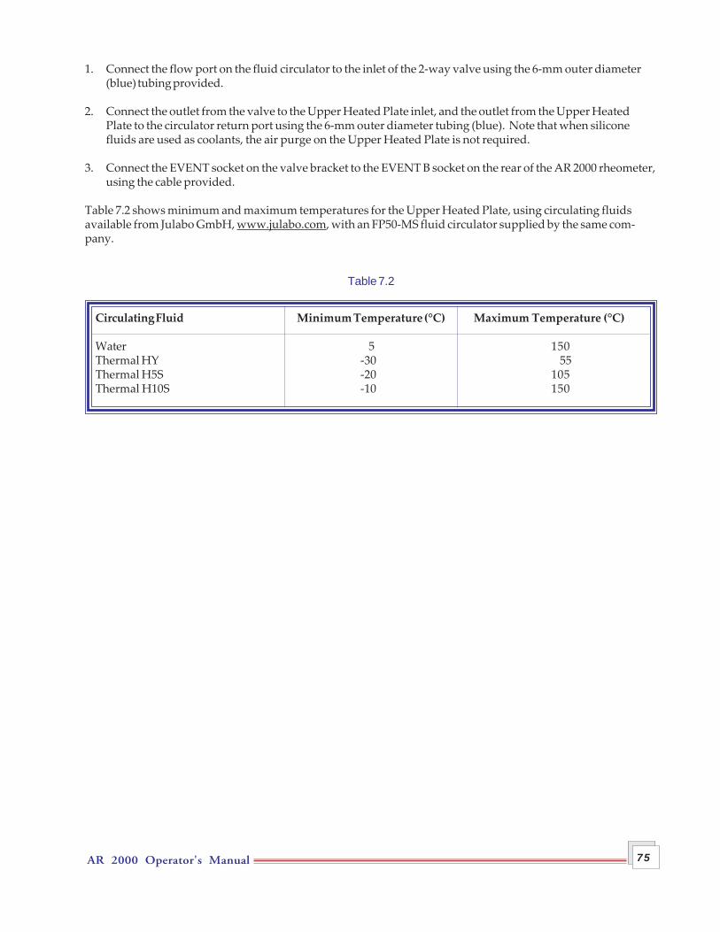
AR 2000 Operator's Manual 75
1. Connect the flow port on the fluid circulator to the inlet of the 2-way valve using the 6-mm outer diameter(blue) tubing provided.
2. Connect the outlet from the valve to the Upper Heated Plate inlet, and the outlet from the Upper HeatedPlate to the circulator return port using the 6-mm outer diameter tubing (blue). Note that when siliconefluids are used as coolants, the air purge on the Upper Heated Plate is not required.
3. Connect the EVENT socket on the valve bracket to the EVENT B socket on the rear of the AR 2000 rheometer,using the cable provided.
Table 7.2 shows minimum and maximum temperatures for the Upper Heated Plate, using circulating fluidsavailable from Julabo GmbH, www.julabo.com, with an FP50-MS fluid circulator supplied by the same com-pany.
Table 7.2
Circulating Fluid Minimum Temperature (°C) Maximum Temperature (°C)
Water 5 150Thermal HY -30 55Thermal H5S -20 105Thermal H10S -10 150
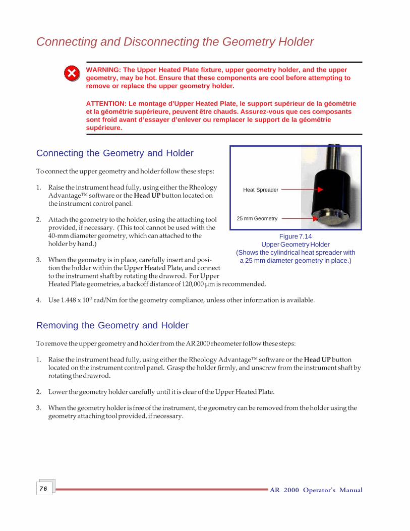
AR 2000 Operator's Manual76
Connecting and Disconnecting the Geometry Holder
WARNING: The Upper Heated Plate fixture, upper geometry holder, and the uppergeometry, may be hot. Ensure that these components are cool before attempting toremove or replace the upper geometry holder.
ATTENTION: Le montage d’Upper Heated Plate, le support supérieur de la géométrieet la géométrie supérieure, peuvent être chauds. Assurez-vous que ces composantssont froid avant d’essayer d’enlever ou remplacer le support de la géométriesupérieure.
Connecting the Geometry and Holder
To connect the upper geometry and holder follow these steps:
1. Raise the instrument head fully, using either the RheologyAdvantage™ software or the Head UP button located onthe instrument control panel.
2. Attach the geometry to the holder, using the attaching toolprovided, if necessary. (This tool cannot be used with the40-mm diameter geometry, which can attached to theholder by hand.)
3. When the geometry is in place, carefully insert and posi-tion the holder within the Upper Heated Plate, and connectto the instrument shaft by rotating the drawrod. For UpperHeated Plate geometries, a backoff distance of 120,000 µm is recommended.
4. Use 1.448 x 10⁻³ rad/Nm for the geometry compliance, unless other information is available.
Removing the Geometry and Holder
To remove the upper geometry and holder from the AR 2000 rheometer follow these steps:
1. Raise the instrument head fully, using either the Rheology Advantage™ software or the Head UP buttonlocated on the instrument control panel. Grasp the holder firmly, and unscrew from the instrument shaft byrotating the drawrod.
2. Lower the geometry holder carefully until it is clear of the Upper Heated Plate.
3. When the geometry holder is free of the instrument, the geometry can be removed from the holder using thegeometry attaching tool provided, if necessary.
25 mm Geometry
Heat Spreader
Figure 7.14Upper Geometry Holder
(Shows the cylindrical heat spreader witha 25 mm diameter geometry in place.)
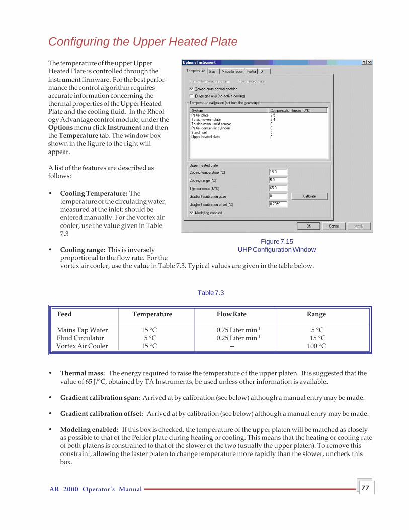
AR 2000 Operator's Manual 77
Configuring the Upper Heated PlateThe temperature of the upper UpperHeated Plate is controlled through theinstrument firmware. For the best perfor-mance the control algorithm requiresaccurate information concerning thethermal properties of the Upper HeatedPlate and the cooling fluid. In the Rheol-ogy Advantage control module, under theOptions menu click Instrument and thenthe Temperature tab. The window boxshown in the figure to the right willappear.
A list of the features are described asfollows:
• Cooling Temperature: Thetemperature of the circulating water,measured at the inlet: should beentered manually. For the vortex aircooler, use the value given in Table7.3
• Cooling range: This is inverselyproportional to the flow rate. For thevortex air cooler, use the value in Table 7.3. Typical values are given in the table below.
Table 7.3
Feed Temperature Flow Rate Range
Mains Tap Water 15 °C 0.75 Liter min-1 5 °C Fluid Circulator 5 °C 0.25 Liter min-1 15 °C Vortex Air Cooler 15 °C -- 100 °C
• Thermal mass: The energy required to raise the temperature of the upper platen. It is suggested that thevalue of 65 J/°C, obtained by TA Instruments, be used unless other information is available.
• Gradient calibration span: Arrived at by calibration (see below) although a manual entry may be made.
• Gradient calibration offset: Arrived at by calibration (see below) although a manual entry may be made.
• Modeling enabled: If this box is checked, the temperature of the upper platen will be matched as closelyas possible to that of the Peltier plate during heating or cooling. This means that the heating or cooling rateof both platens is constrained to that of the slower of the two (usually the upper platen). To remove thisconstraint, allowing the faster platen to change temperature more rapidly than the slower, uncheck thisbox.
Figure 7.15UHP Configuration Window
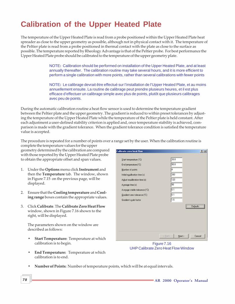
AR 2000 Operator's Manual78
Calibration of the Upper Heated PlateThe temperature of the Upper Heated Plate is read from a probe positioned within the Upper Heated Plate heatspreader as close to the upper geometry as possible, although not in physical contact with it. The temperature ofthe Peltier plate is read from a probe positioned in thermal contact with the plate as close to the surface aspossible. The temperature reported by Rheology Advantage is that of the Peltier probe. For best performance theUpper Heated Plate probe should be calibrated to the temperature of the upper geometry plate.
NOTE: Calibration should be performed on installation of the Upper Heated Plate, and at leastannually thereafter. The calibration routine may take several hours, and it is more efficient toperform a single calibration with more points, rather than several calibrations with fewer points
NOTE: Le calibrage devrait être effectué sur l’installation de l’Upper Heated Plate, et au moinsannuellement ensuite. La routine de calibrage peut prendre plusieurs heures, et il est plusefficace d’effectuer un calibrage simple avec plus de points, plutôt que plusieurs calibragesavec peu de points.
During the automatic calibration routine a heat flow sensor is used to determine the temperature gradientbetween the Peltier plate and the upper geometry. The gradient is reduced to within preset tolerances by adjust-ing the temperature of the Upper Heated Plate while the temperature of the Peltier plate is held constant. Aftereach adjustment a user-defined stability criterion is applied and, once temperature stability is achieved, com-parison is made with the gradient tolerance. When the gradient tolerance condition is satisfied the temperaturevalue is accepted.
The procedure is repeated for a number of points over a range set by the user. When the calibration routine iscomplete the temperature values for the uppergeometry determined by the calibration are comparedwith those reported by the Upper Heated Plate probeto obtain the appropriate offset and span values.
1. Under the Options menu click Instrument andthen the Temperature tab. The window, shownin Figure 7.15 on the previous page, will bedisplayed.
2. Ensure that the Cooling temperature and Cool-ing range boxes contain the appropriate values.
3. Click Calibrate. The Calibrate Zero Heat Flowwindow, shown in Figure 7.16 shown to theright, will be displayed.
The parameters shown on the window aredescribed as follows:
• Start Temperature: Temperature at whichcalibration is to begin.
• End Temperature: Temperature at whichcalibration is to end.
• Number of Points: Number of temperature points, which will be at equal intervals.
Figure 7.16UHP Calibrate Zero Heat Flow Window
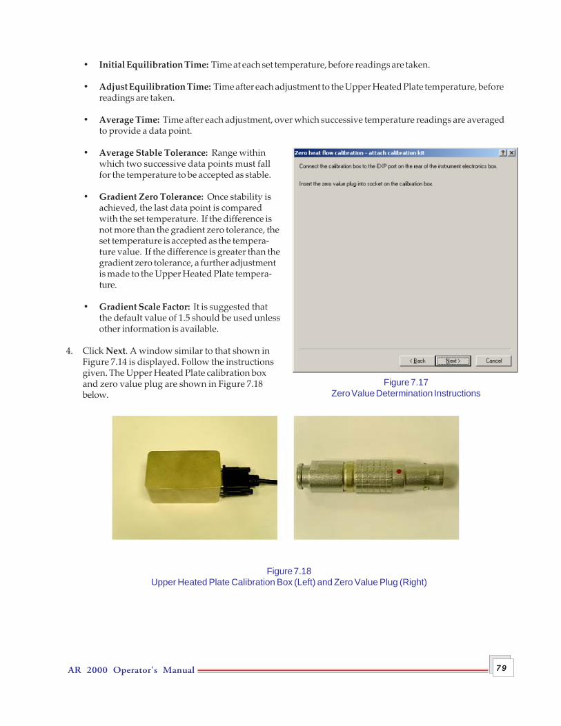
AR 2000 Operator's Manual 79
• Initial Equilibration Time: Time at each set temperature, before readings are taken.
• Adjust Equilibration Time: Time after each adjustment to the Upper Heated Plate temperature, beforereadings are taken.
• Average Time: Time after each adjustment, over which successive temperature readings are averagedto provide a data point.
• Average Stable Tolerance: Range withinwhich two successive data points must fallfor the temperature to be accepted as stable.
• Gradient Zero Tolerance: Once stability isachieved, the last data point is comparedwith the set temperature. If the difference isnot more than the gradient zero tolerance, theset temperature is accepted as the tempera-ture value. If the difference is greater than thegradient zero tolerance, a further adjustmentis made to the Upper Heated Plate tempera-ture.
• Gradient Scale Factor: It is suggested thatthe default value of 1.5 should be used unlessother information is available.
4. Click Next. A window similar to that shown inFigure 7.14 is displayed. Follow the instructionsgiven. The Upper Heated Plate calibration boxand zero value plug are shown in Figure 7.18below.
Figure 7.18Upper Heated Plate Calibration Box (Left) and Zero Value Plug (Right)
Figure 7.17Zero Value Determination Instructions
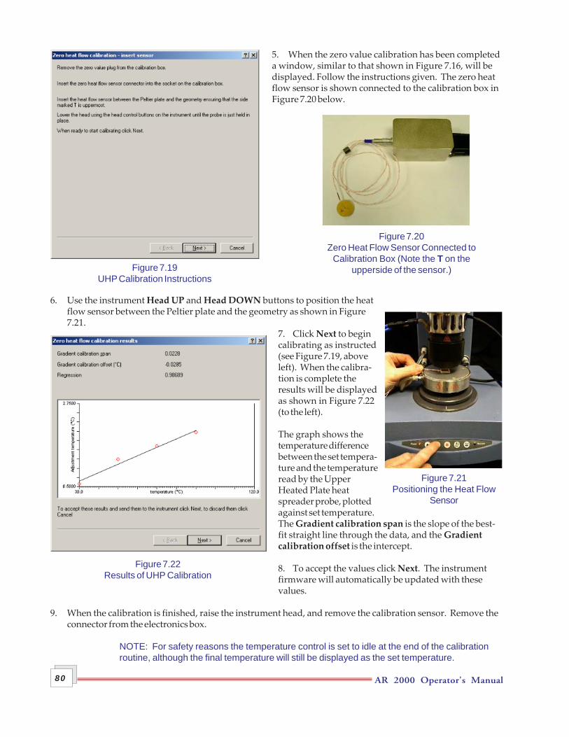
AR 2000 Operator's Manual80
5. When the zero value calibration has been completeda window, similar to that shown in Figure 7.16, will bedisplayed. Follow the instructions given. The zero heatflow sensor is shown connected to the calibration box inFigure 7.20 below.
6. Use the instrument Head UP and Head DOWN buttons to position the heatflow sensor between the Peltier plate and the geometry as shown in Figure7.21.
7. Click Next to begincalibrating as instructed(see Figure 7.19, aboveleft). When the calibra-tion is complete theresults will be displayedas shown in Figure 7.22(to the left).
The graph shows thetemperature differencebetween the set tempera-ture and the temperatureread by the UpperHeated Plate heatspreader probe, plottedagainst set temperature.The Gradient calibration span is the slope of the best-fit straight line through the data, and the Gradientcalibration offset is the intercept.
8. To accept the values click Next. The instrumentfirmware will automatically be updated with thesevalues.
9. When the calibration is finished, raise the instrument head, and remove the calibration sensor. Remove theconnector from the electronics box.
NOTE: For safety reasons the temperature control is set to idle at the end of the calibrationroutine, although the final temperature will still be displayed as the set temperature.
Figure 7.20Zero Heat Flow Sensor Connected to
Calibration Box (Note the T on theupperside of the sensor.)
Figure 7.21Positioning the Heat Flow
Sensor
Figure 7.19UHP Calibration Instructions
Figure 7.22Results of UHP Calibration
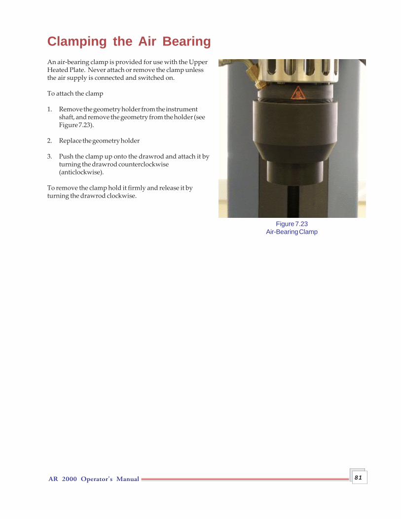
AR 2000 Operator's Manual 81
Clamping the Air BearingAn air-bearing clamp is provided for use with the UpperHeated Plate. Never attach or remove the clamp unlessthe air supply is connected and switched on.
To attach the clamp
1. Remove the geometry holder from the instrumentshaft, and remove the geometry from the holder (seeFigure 7.23).
2. Replace the geometry holder
3. Push the clamp up onto the drawrod and attach it byturning the drawrod counterclockwise(anticlockwise).
To remove the clamp hold it firmly and release it byturning the drawrod clockwise.
Figure 7.23Air-Bearing Clamp

AR 2000 Operator's Manual82
Using an Inert Gas AtmosphereMany samples experience oxidation at elevated temperatures—an atmoshere of inert gas such as nitrogen orargon can be used to prevent this. The gas supply should be regulated to less than 40 psi (2.8 bar) beforeconnection to the Upper Heated Plate. A gas flow meter (not supplied) should be used to set the gas flow rate.
1. Connect the gas supply to the inlet port on the gas flow meter.
2. Connect the outlet port on the flow meter to the inert gas inlet port on the Upper Heated Plate using 4-mmouter diameter tubing (white) and the connector provided.
3. Set the inert gas flow rate at 1 Liter per minute (L/min). If the gas flow rate is set too high, temperaturecontrol of the Upper Heated Plate may be affected.
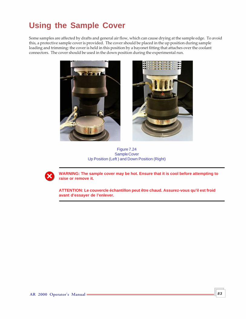
AR 2000 Operator's Manual 83
Using the Sample CoverSome samples are affected by drafts and general air flow, which can cause drying at the sample edge. To avoidthis, a protective sample cover is provided. The cover should be placed in the up position during sampleloading and trimming: the cover is held in this position by a bayonet fitting that attaches over the coolantconnectors. The cover should be used in the down position during the experimental run.
Figure 7.24Sample Cover
Up Position (Left ) and Down Position (Right)
WARNING: The sample cover may be hot. Ensure that it is cool before attempting toraise or remove it.
ATTENTION: Le couvercle échantillon peut être chaud. Assurez-vous qu’il est froidavant d’essayer de l’enlever.

AR 2000 Operator's Manual84

AR 2000 Operator’s Manual 85
Chapter 8 The Pressure Cell
Overview
WARNING: TA Instruments' Pressure Cell is designed for use at temperatures up to 150°C and pressures up to 138 bar (2000 psi). At all times during the use of the cell, wear safety glasses and clothing that afford adequate protection against the sample under test, and the temperature and pressure used. At other than ambient temperature, the outer surfaces of the cell may become very hot or cold. When operating at these temperatures, wear gloves that afford adequate protection against the surface temperature of the pressure cell and its fittings.
The Pressure Cell is used with the standard concentric cylinder, Peltier-controlled, heating jacket. A copper sheath is fitted to the cell to ensure good heat transmission between the jacket and the cell.
The Pressure Cell may be used either in self-pressuring mode, in which the pressure is produced by the volatility of the sample, or in external pressurization mode, with an applied pressure of up to 138 bar (2000 psi). In this chapter, the pressure cell assembly and operation for both modes are described.
NOTE: For external pressurization, the user of the cell is required to provide a high-pressure source, and suitable pressure-rated connections to a 1/8-inch or 1/4-inch NPT female fitting.
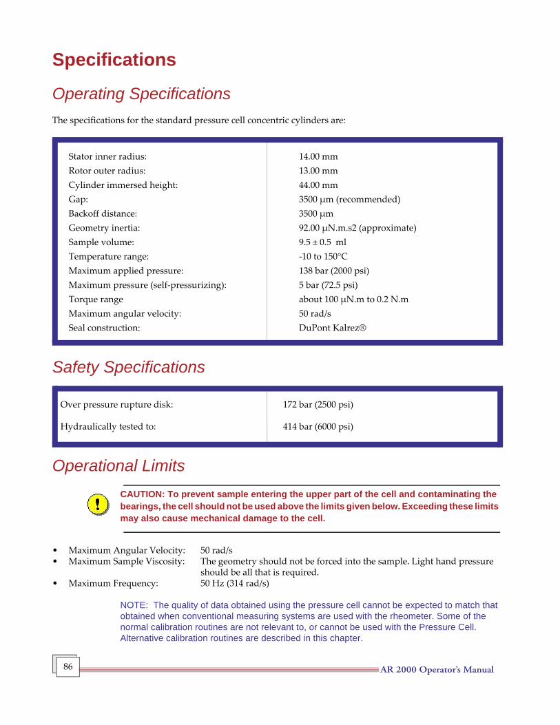
AR 2000 Operator’s Manual 86
Specifications
Operating SpecificationsThe specifications for the standard pressure cell concentric cylinders are:
Stator inner radius: 14.00 mmRotor outer radius: 13.00 mmCylinder immersed height: 44.00 mmGap: 3500 µm (recommended)Backoff distance: 3500 µmGeometry inertia: 92.00 µN.m.s2 (approximate)Sample volume: 9.5 ± 0.5 mlTemperature range: -10 to 150°CMaximum applied pressure: 138 bar (2000 psi)Maximum pressure (self-pressurizing): 5 bar (72.5 psi)Torque range about 100 µN.m to 0.2 N.mMaximum angular velocity: 50 rad/sSeal construction: DuPont Kalrez®
Safety Specifications
Over pressure rupture disk: 172 bar (2500 psi)
Hydraulically tested to: 414 bar (6000 psi)
Operational LimitsCAUTION: To prevent sample entering the upper part of the cell and contaminating the bearings, the cell should not be used above the limits given below. Exceeding these limits may also cause mechanical damage to the cell.
• Maximum Angular Velocity: 50 rad/s• Maximum Sample Viscosity: The geometry should not be forced into the sample. Light hand pressure
should be all that is required. • Maximum Frequency: 50 Hz (314 rad/s)
NOTE: The quality of data obtained using the pressure cell cannot be expected to match that obtained when conventional measuring systems are used with the rheometer. Some of the normal calibration routines are not relevant to, or cannot be used with the Pressure Cell. Alternative calibration routines are described in this chapter.
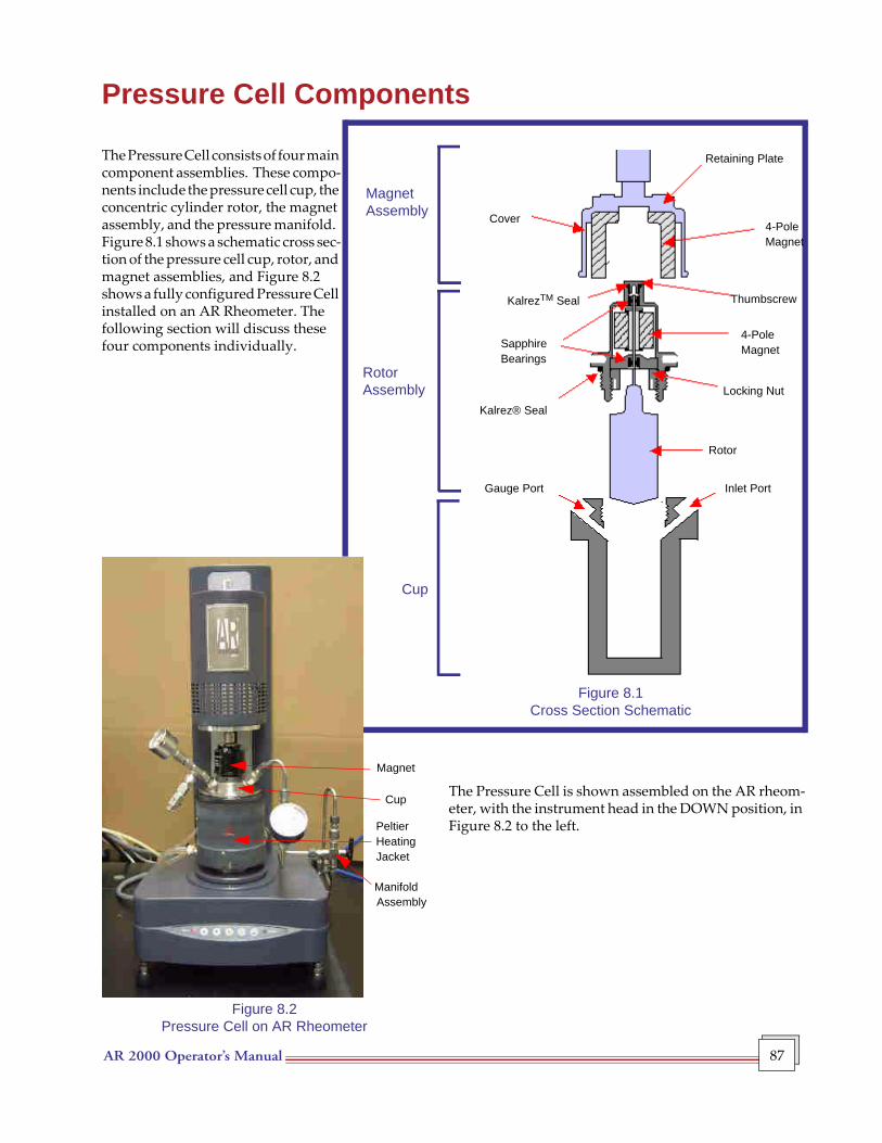
AR 2000 Operator’s Manual 87
Pressure Cell Components
The Pressure Cell consists of four main component assemblies. These compo-nents include the pressure cell cup, the concentric cylinder rotor, the magnet assembly, and the pressure manifold. Figure 8.1 shows a schematic cross sec-tion of the pressure cell cup, rotor, and magnet assemblies, and Figure 8.2 shows a fully configured Pressure Cell installed on an AR Rheometer. The following section will discuss these four components individually.
The Pressure Cell is shown assembled on the AR rheom-eter, with the instrument head in the DOWN position, in Figure 8.2 to the left.
Magnet
Cup
PeltierHeatingJacket
ManifoldAssembly
Figure 8.2Pressure Cell on AR Rheometer
Cup
Cover
Retaining Plate
KalrezTM Seal
SapphireBearings
Gauge Port
4-PoleMagnet
Thumbscrew
Locking Nut
Rotor
Inlet Port
Kalrez® Seal
4-PoleMagnet
Magnet Assembly
Rotor Assembly
Figure 8.1Cross Section Schematic
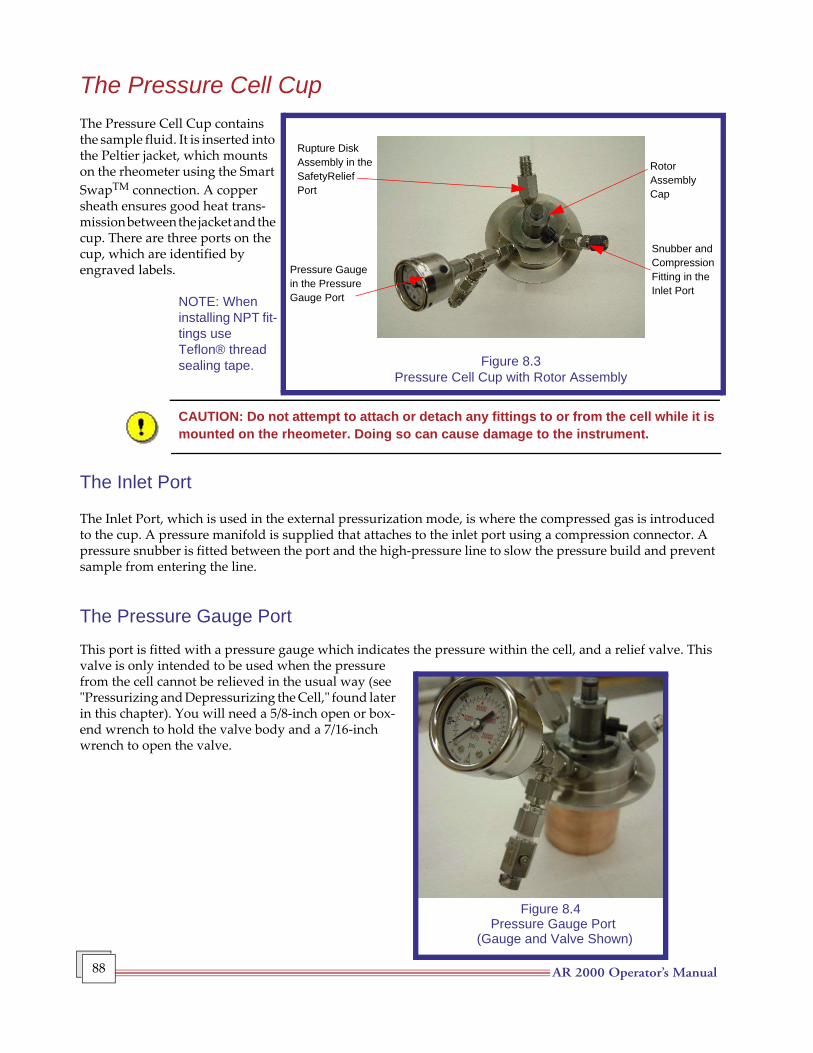
AR 2000 Operator’s Manual 88
The Pressure Cell CupThe Pressure Cell Cup contains the sample fluid. It is inserted into the Peltier jacket, which mounts on the rheometer using the Smart SwapTM connection. A copper sheath ensures good heat trans-mission between the jacket and the cup. There are three ports on the cup, which are identified by engraved labels.
NOTE: When installing NPT fit-tings use Teflon® thread sealing tape.
CAUTION: Do not attempt to attach or detach any fittings to or from the cell while it is mounted on the rheometer. Doing so can cause damage to the instrument.
The Inlet Port
The Inlet Port, which is used in the external pressurization mode, is where the compressed gas is introduced to the cup. A pressure manifold is supplied that attaches to the inlet port using a compression connector. A pressure snubber is fitted between the port and the high-pressure line to slow the pressure build and prevent sample from entering the line.
The Pressure Gauge Port
This port is fitted with a pressure gauge which indicates the pressure within the cell, and a relief valve. This valve is only intended to be used when the pressure from the cell cannot be relieved in the usual way (see "Pressurizing and Depressurizing the Cell," found later in this chapter). You will need a 5/8-inch open or box-end wrench to hold the valve body and a 7/16-inch wrench to open the valve.
Figure 8.3Pressure Cell Cup with Rotor Assembly
Rupture DiskAssembly in theSafetyReliefPort
Pressure Gaugein the PressureGauge Port
RotorAssemblyCap
Snubber andCompressionFitting in the Inlet Port
Figure 8.4Pressure Gauge Port
(Gauge and Valve Shown)
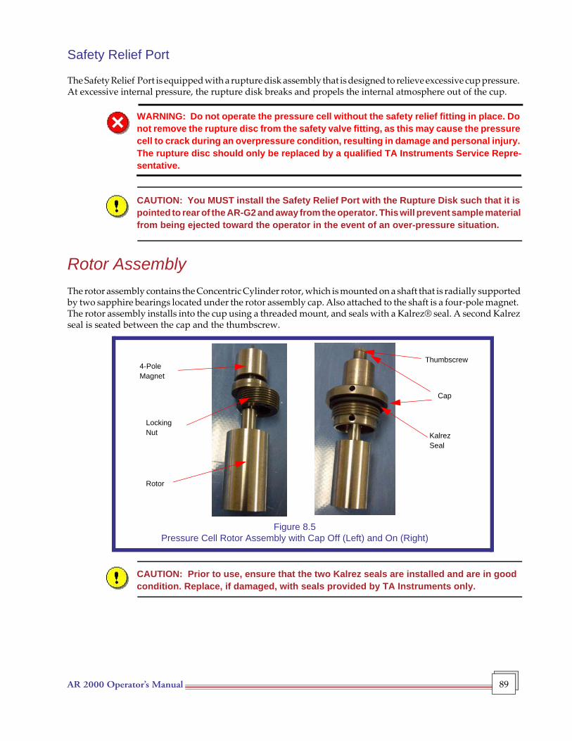
AR 2000 Operator’s Manual 89
Safety Relief Port
The Safety Relief Port is equipped with a rupture disk assembly that is designed to relieve excessive cup pressure. At excessive internal pressure, the rupture disk breaks and propels the internal atmosphere out of the cup.
WARNING: Do not operate the pressure cell without the safety relief fitting in place. Do not remove the rupture disc from the safety valve fitting, as this may cause the pressure cell to crack during an overpressure condition, resulting in damage and personal injury. The rupture disc should only be replaced by a qualified TA Instruments Service Repre-sentative.
CAUTION: You MUST install the Safety Relief Port with the Rupture Disk such that it is pointed to rear of the AR-G2 and away from the operator. This will prevent sample material from being ejected toward the operator in the event of an over-pressure situation.
Rotor AssemblyThe rotor assembly contains the Concentric Cylinder rotor, which is mounted on a shaft that is radially supported by two sapphire bearings located under the rotor assembly cap. Also attached to the shaft is a four-pole magnet. The rotor assembly installs into the cup using a threaded mount, and seals with a Kalrez® seal. A second Kalrez seal is seated between the cap and the thumbscrew.
Figure 8.5Pressure Cell Rotor Assembly with Cap Off (Left) and On (Right)
CAUTION: Prior to use, ensure that the two Kalrez seals are installed and are in good condition. Replace, if damaged, with seals provided by TA Instruments only.
4-PoleMagnet
LockingNut
Rotor
Thumbscrew
Cap
KalrezSeal
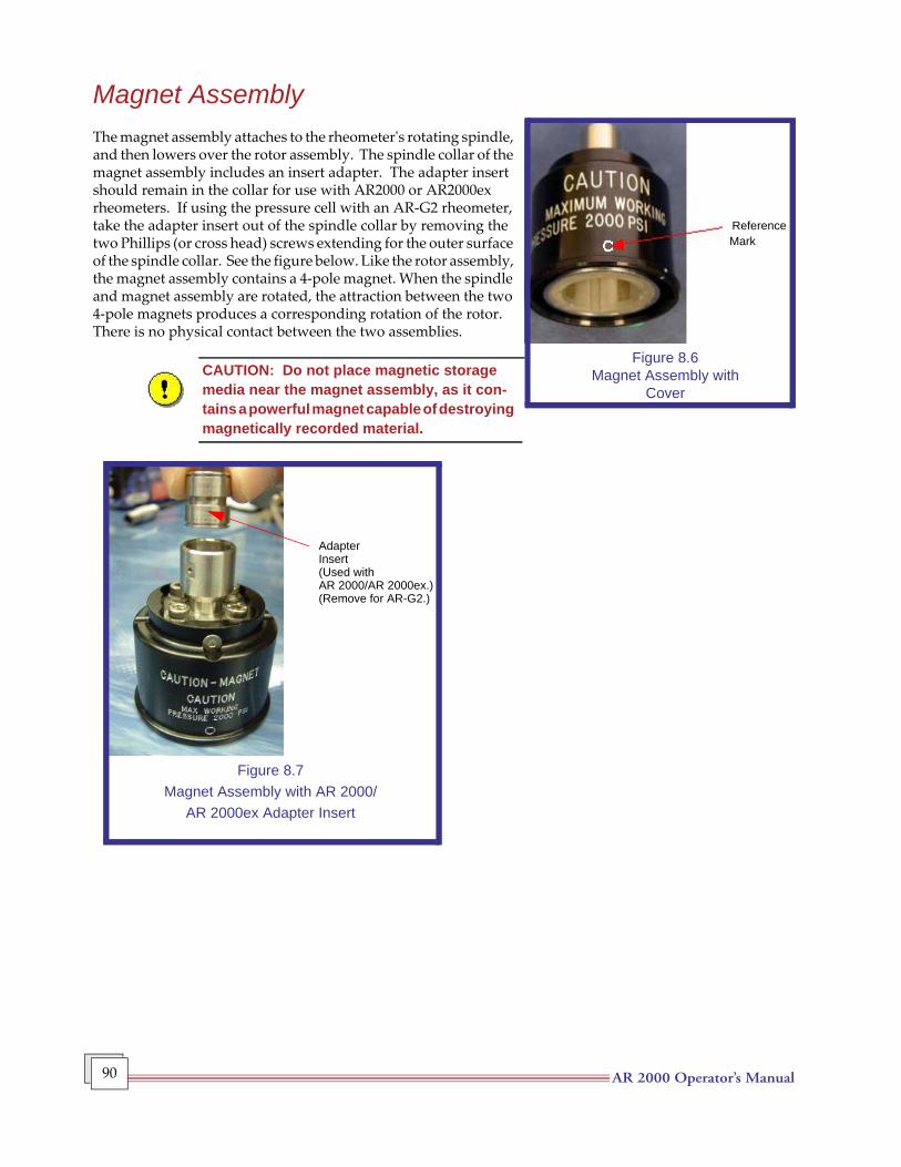
AR 2000 Operator’s Manual 90
Magnet AssemblyThe magnet assembly attaches to the rheometer's rotating spindle, and then lowers over the rotor assembly. The spindle collar of the magnet assembly includes an insert adapter. The adapter insert should remain in the collar for use with AR2000 or AR2000ex rheometers. If using the pressure cell with an AR-G2 rheometer, take the adapter insert out of the spindle collar by removing the two Phillips (or cross head) screws extending for the outer surface of the spindle collar. See the figure below. Like the rotor assembly, the magnet assembly contains a 4-pole magnet. When the spindle and magnet assembly are rotated, the attraction between the two 4-pole magnets produces a corresponding rotation of the rotor. There is no physical contact between the two assemblies.
CAUTION: Do not place magnetic storage media near the magnet assembly, as it con-tains a powerful magnet capable of destroying magnetically recorded material.
Figure 8.6Magnet Assembly with
Cover
ReferenceMark
Figure 8.7Magnet Assembly with AR 2000/
AR 2000ex Adapter Insert
AdapterInsert(Used withAR 2000/AR 2000ex.)(Remove for AR-G2.)
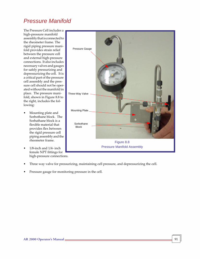
AR 2000 Operator’s Manual 91
Pressure ManifoldThe Pressure Cell includes a high-pressure manifold assembly that is connected to the rheometer frame. The rigid piping pressure mani-fold provides strain relief between the pressure cell and external high-pressure connections. It also includes necessary valves and gauges for safely pressurizing and depressurizing the cell. It is a critical part of the pressure cell assembly and the pres-sure cell should not be oper-ated without the manifold in place. The pressure mani-fold, shown in Figure 8.8 to the right, includes the fol-lowing:
• Mounting plate and Sorbothane block. The Sorbathane block is a flexible material that provides flex between the rigid pressure cell piping assembly and the rheometer frame.
• 1/8-inch and 1/4- inch female NPT fittings for high-pressure connections.
• Three way valve for pressurizing, maintaining cell pressure, and depressurizing the cell.
• Pressure gauge for monitoring pressure in the cell.
Pressure Gauge
Three-Way Valve
Mounting Plate
SorbothaneBlock
Figure 8.8Pressure Manifold Assembly
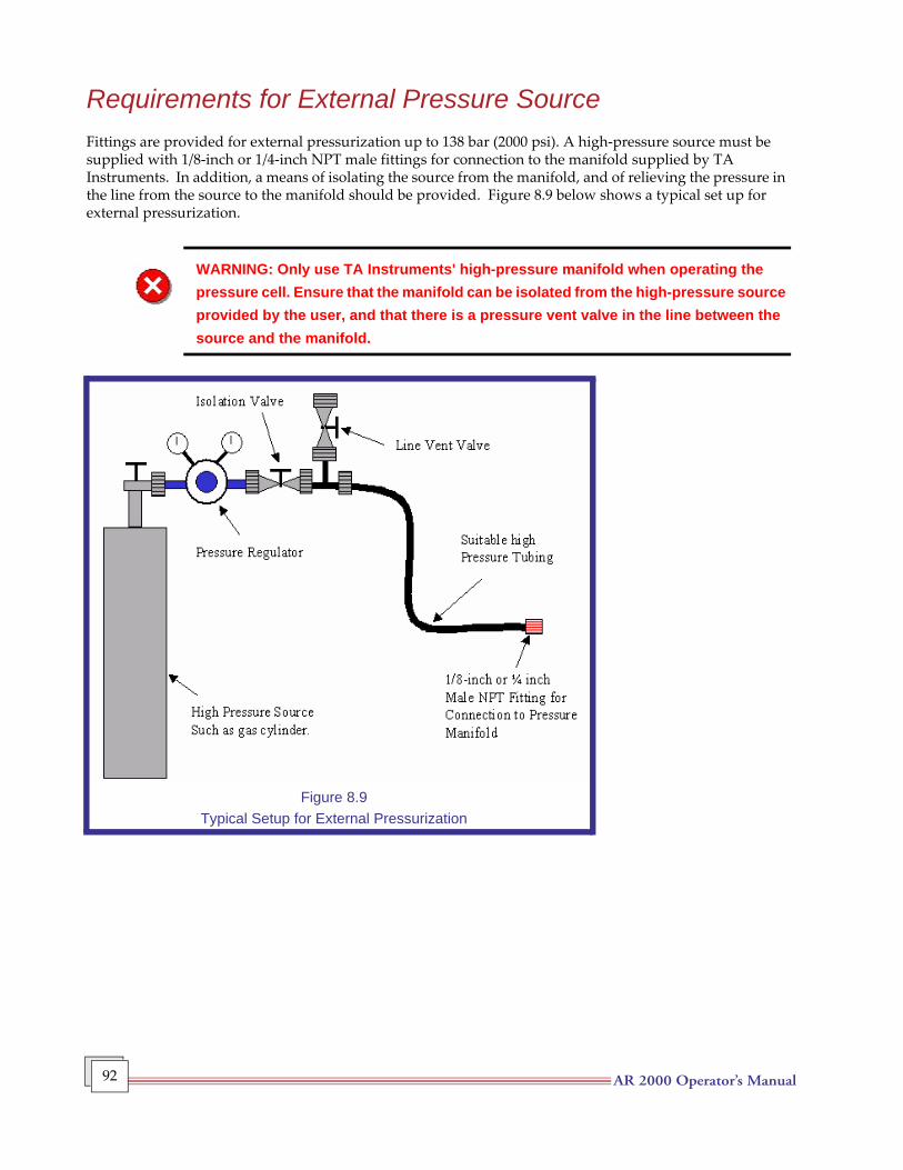
AR 2000 Operator’s Manual 92
Requirements for External Pressure Source Fittings are provided for external pressurization up to 138 bar (2000 psi). A high-pressure source must be supplied with 1/8-inch or 1/4-inch NPT male fittings for connection to the manifold supplied by TA Instruments. In addition, a means of isolating the source from the manifold, and of relieving the pressure in the line from the source to the manifold should be provided. Figure 8.9 below shows a typical set up for external pressurization.
WARNING: Only use TA Instruments' high-pressure manifold when operating the pressure cell. Ensure that the manifold can be isolated from the high-pressure source provided by the user, and that there is a pressure vent valve in the line between the source and the manifold.
Figure 8.9Typical Setup for External Pressurization
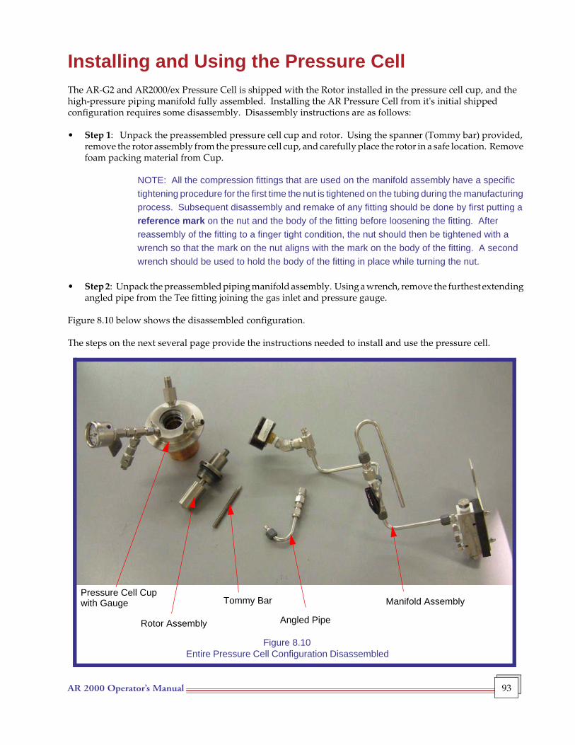
AR 2000 Operator’s Manual 93
Installing and Using the Pressure CellThe AR-G2 and AR2000/ex Pressure Cell is shipped with the Rotor installed in the pressure cell cup, and the high-pressure piping manifold fully assembled. Installing the AR Pressure Cell from it's initial shipped configuration requires some disassembly. Disassembly instructions are as follows:
• Step 1: Unpack the preassembled pressure cell cup and rotor. Using the spanner (Tommy bar) provided, remove the rotor assembly from the pressure cell cup, and carefully place the rotor in a safe location. Remove foam packing material from Cup.
NOTE: All the compression fittings that are used on the manifold assembly have a specific tightening procedure for the first time the nut is tightened on the tubing during the manufacturing process. Subsequent disassembly and remake of any fitting should be done by first putting a reference mark on the nut and the body of the fitting before loosening the fitting. After reassembly of the fitting to a finger tight condition, the nut should then be tightened with a wrench so that the mark on the nut aligns with the mark on the body of the fitting. A second wrench should be used to hold the body of the fitting in place while turning the nut.
• Step 2: Unpack the preassembled piping manifold assembly. Using a wrench, remove the furthest extending angled pipe from the Tee fitting joining the gas inlet and pressure gauge.
Figure 8.10 below shows the disassembled configuration.
The steps on the next several page provide the instructions needed to install and use the pressure cell.
Pressure Cell Cup
Rotor Assembly
Tommy Bar
Angled Pipe
Manifold Assemblywith Gauge
Figure 8.10 Entire Pressure Cell Configuration Disassembled
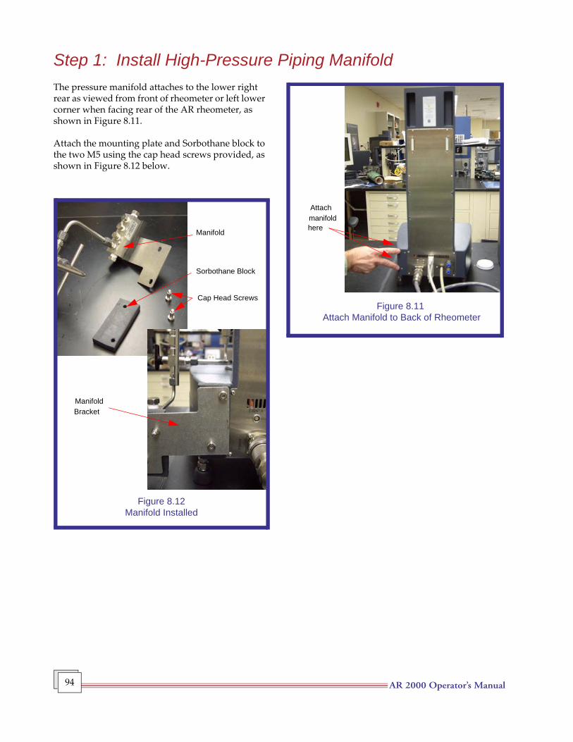
AR 2000 Operator’s Manual 94
Step 1: Install High-Pressure Piping ManifoldThe pressure manifold attaches to the lower right rear as viewed from front of rheometer or left lower corner when facing rear of the AR rheometer, as shown in Figure 8.11.
Attach the mounting plate and Sorbothane block to the two M5 using the cap head screws provided, as shown in Figure 8.12 below.
Attach
here
Figure 8.11 Attach Manifold to Back of Rheometer
manifold
Manifold
Sorbothane Block
Cap Head Screws
Figure 8.12Manifold Installed
ManifoldBracket
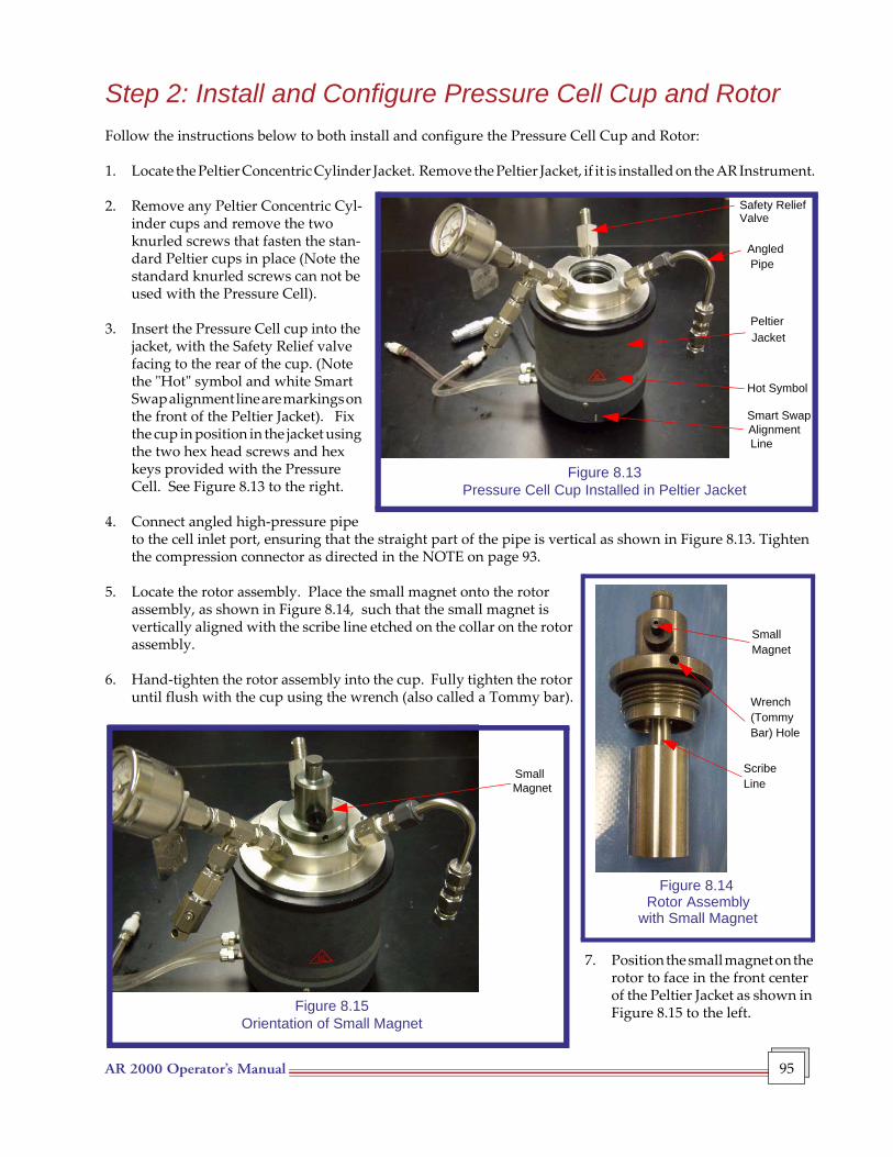
AR 2000 Operator’s Manual 95
Step 2: Install and Configure Pressure Cell Cup and RotorFollow the instructions below to both install and configure the Pressure Cell Cup and Rotor:
1. Locate the Peltier Concentric Cylinder Jacket. Remove the Peltier Jacket, if it is installed on the AR Instrument.
2. Remove any Peltier Concentric Cyl-inder cups and remove the two knurled screws that fasten the stan-dard Peltier cups in place (Note the standard knurled screws can not be used with the Pressure Cell).
3. Insert the Pressure Cell cup into the
jacket, with the Safety Relief valve facing to the rear of the cup. (Note the "Hot" symbol and white Smart Swap alignment line are markings on the front of the Peltier Jacket). Fix the cup in position in the jacket using the two hex head screws and hex keys provided with the Pressure Cell. See Figure 8.13 to the right.
4. Connect angled high-pressure pipe
to the cell inlet port, ensuring that the straight part of the pipe is vertical as shown in Figure 8.13. Tighten the compression connector as directed in the NOTE on page 93.
5. Locate the rotor assembly. Place the small magnet onto the rotor assembly, as shown in Figure 8.14, such that the small magnet is vertically aligned with the scribe line etched on the collar on the rotor assembly.
6. Hand-tighten the rotor assembly into the cup. Fully tighten the rotor until flush with the cup using the wrench (also called a Tommy bar).
7. Position the small magnet on the rotor to face in the front center of the Peltier Jacket as shown in Figure 8.15 to the left.
SmallMagnet
Wrench(TommyBar) Hole
ScribeLine
Figure 8.14 Rotor Assembly
with Small Magnet
Safety Relief
AngledPipe
PeltierJacket
Hot Symbol
Smart SwapAlignmentLine
Figure 8.13Pressure Cell Cup Installed in Peltier Jacket
Valve
SmallMagnet
Figure 8.15Orientation of Small Magnet
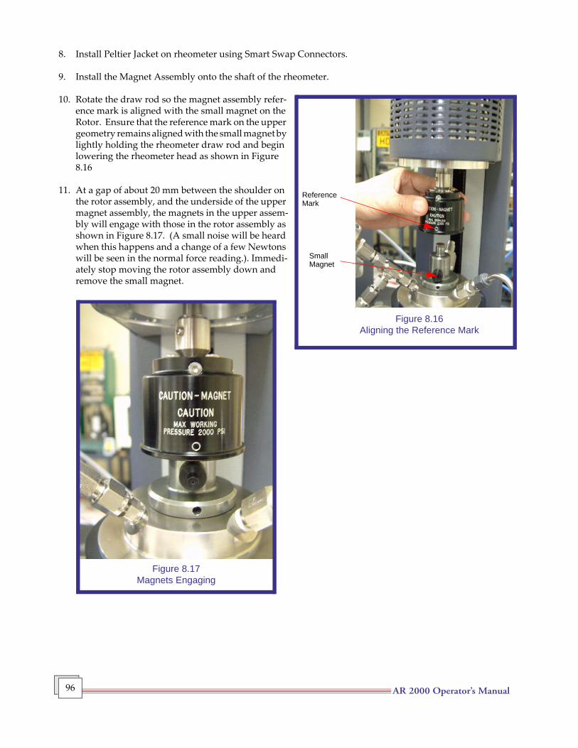
AR 2000 Operator’s Manual 96
8. Install Peltier Jacket on rheometer using Smart Swap Connectors.
9. Install the Magnet Assembly onto the shaft of the rheometer.
10. Rotate the draw rod so the magnet assembly refer-ence mark is aligned with the small magnet on the Rotor. Ensure that the reference mark on the upper geometry remains aligned with the small magnet by lightly holding the rheometer draw rod and begin lowering the rheometer head as shown in Figure 8.16
11. At a gap of about 20 mm between the shoulder on
the rotor assembly, and the underside of the upper magnet assembly, the magnets in the upper assem-bly will engage with those in the rotor assembly as shown in Figure 8.17. (A small noise will be heard when this happens and a change of a few Newtons will be seen in the normal force reading.). Immedi-ately stop moving the rotor assembly down and remove the small magnet.
Figure 8.16Aligning the Reference Mark
ReferenceMark
SmallMagnet
Figure 8.17Magnets Engaging
AR 2000 Operator’s Manual 97
Step 3: Positioning Gap and Pressure Cell CalibrationsOnce the Pressure Cell cup and rotor have been installed, you will need to position the gap and perform the calibrations as directed in this section.
CAUTION: The standard calibration routines used by Rheology Advantage for zero gap, geometry inertia and bearing friction are not suitable for use with the pressure cell. When the pressure cell is selected as the measuring geometry, these routines are either disabled or are replaced by more appropriate routines. Do not attempt to use or calibrate the pressure cell unless this geometry is selected.
1. Ensuring that the pressure cell geometry is selected in the software, find the gap zero position. Do not request the instrument to raise the head to the backoff distance. Set a gap of 3500 µm.
2. When the Pressure Cell is the selected geometry on an AR2000 or AR2000ex, the Gap Zero Mode of normal force with a value of 5N will be used. This will override any other settings in Rheology Advantage software.
3. Conduct the Bearing Friction Calibration. The bearing friction routine used when the Pressure Cell is selected as the geometry is slightly different from the standard routine. The calibration should be conducted at a geometry gap of 3500 µm. The bearing friction calibration must be done again when another measuring system is used. A typical value for the Pressure Cell should be between 8 and 15 µN.m / (rad/s). This is about ten times higher than for other geometries.
4. Map the Air Bearing. Perform a rotational mapping at a gap of 3500 µm using the Standard mapping routine.
NOTE: DO NOT USE PRECISION OR EXTENDED MAPPING ROUTINES WITH THE PRES-SURE CELL.
CAUTION: It is important that the bearing is re-mapped before any other measuring system is used.
NOTE: When changing to other geometries, Rheology Advantage does not restore the previous settings. However, the mapping table is cleared and the bearing friction is reset to zero. Any functions that were previously unavailable are reactivated and the gap zero mode settings are restored, because the settings were not overwritten.
5. Check the Cell by running peak-hold test at 0.05 rad/s and a duration time of 126 sec. The peak-to-peak residual torque should not be larger than 100 µN.m.
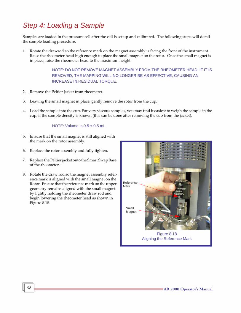
AR 2000 Operator’s Manual 98
Step 4: Loading a SampleSamples are loaded in the pressure cell after the cell is set up and calibrated. The following steps will detail the sample loading procedure.
1. Rotate the drawrod so the reference mark on the magnet assembly is facing the front of the instrument. Raise the rheometer head high enough to place the small magnet on the rotor. Once the small magnet is in place, raise the rheometer head to the maximum height.
NOTE: DO NOT REMOVE MAGNET ASSEMBLY FROM THE RHEOMETER HEAD. IF IT IS REMOVED, THE MAPPING WILL NO LONGER BE AS EFFECTIVE, CAUSING AN INCREASE IN RESIDUAL TORQUE.
2. Remove the Peltier jacket from rheometer.
3. Leaving the small magnet in place, gently remove the rotor from the cup.
4. Load the sample into the cup. For very viscous samples, you may find it easiest to weigh the sample in the cup, if the sample density is known (this can be done after removing the cup from the jacket).
NOTE: Volume is 9.5 ± 0.5 mL.
5. Ensure that the small magnet is still aligned with the mark on the rotor assembly.
6. Replace the rotor assembly and fully tighten.
7. Replace the Peltier jacket onto the Smart Swap Base of the rheometer.
8. Rotate the draw rod so the magnet assembly refer-ence mark is aligned with the small magnet on the Rotor. Ensure that the reference mark on the upper geometry remains aligned with the small magnet by lightly holding the rheometer draw rod and begin lowering the rheometer head as shown in Figure 8.18.
Figure 8.18Aligning the Reference Mark
ReferenceMark
SmallMagnet
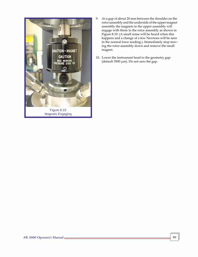
AR 2000 Operator’s Manual 99
9. At a gap of about 20 mm between the shoulder on the rotor assembly and the underside of the upper magnet assembly the magnets in the upper assembly will engage with those in the rotor assembly as shown in Figure 8.19. (A small noise will be heard when this happens and a change of a few Newtons will be seen in the normal force reading.). Immediately stop mov-ing the rotor assembly down and remove the small magnet.
10. Lower the instrument head to the geometry gap (default 3500 µm). Do not zero the gap.
Figure 8.19Magnets Engaging
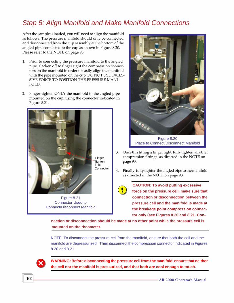
AR 2000 Operator’s Manual 100
Step 5: Align Manifold and Make Manifold ConnectionsAfter the sample is loaded, you will need to align the manifold as follows. The pressure manifold should only be connected and disconnected from the cup assembly at the bottom of the angled pipe connected to the cup as shown in Figure 8.20. Please refer to the NOTE on page 93.
1. Prior to connecting the pressure manifold to the angled pipe, slacken off to finger tight the compression connec-tors on the manifold in order to easily align the manifold with the pipe mounted on the cup. DO NOT USE EXCES-SIVE FORCE TO POSITION THE PRESSURE MANI-FOLD.
2. Finger-tighten ONLY the manifold to the angled pipe mounted on the cup, using the connector indicated in Figure 8.21.
3. Once this fitting is finger tight, fully tighten all other compression fittings as directed in the NOTE on page 93.
4. Finally, fully tighten the angled pipe to the manifold as directed in the NOTE on page 93.
CAUTION: To avoid putting excessive force on the pressure cell, make sure that connection or disconnection between the pressure cell and the manifold is made at the breakage point compression connec-tor only (see Figures 8.20 and 8.21. Con-
nection or disconnection should be made at no other point while the pressure cell is mounted on the rheometer.
NOTE: To disconnect the pressure cell from the manifold, ensure that both the cell and the manifold are depressurized. Then disconnect the compression connector indicated in Figures 8.20 and 8.21.
WARNING: Before disconnecting the pressure cell from the manifold, ensure that neither the cell nor the manifold is pressurized, and that both are cool enough to touch.
Figure 8.20Place to Connect/Disconnect Manifold
Figure 8.21Connector Used to
Connect/Disconnect Manifold
FingerTightenThisConnector
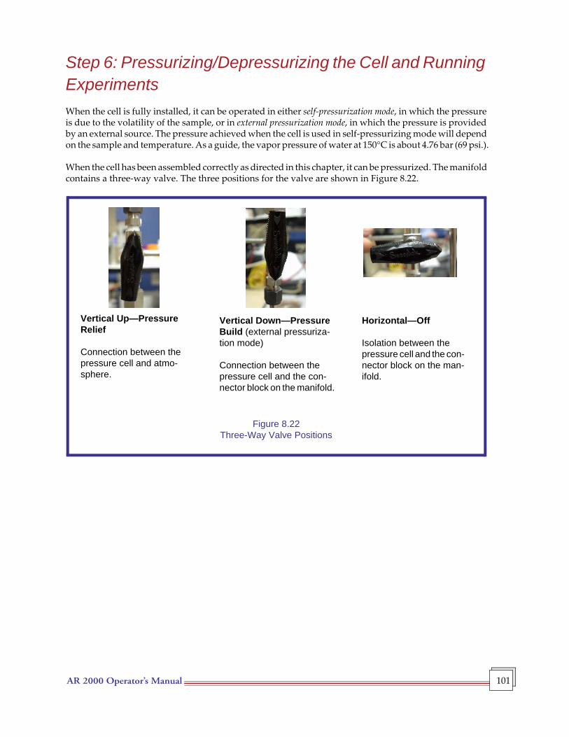
AR 2000 Operator’s Manual 101
Step 6: Pressurizing/Depressurizing the Cell and Running ExperimentsWhen the cell is fully installed, it can be operated in either self-pressurization mode, in which the pressure is due to the volatility of the sample, or in external pressurization mode, in which the pressure is provided by an external source. The pressure achieved when the cell is used in self-pressurizing mode will depend on the sample and temperature. As a guide, the vapor pressure of water at 150°C is about 4.76 bar (69 psi.).
When the cell has been assembled correctly as directed in this chapter, it can be pressurized. The manifold contains a three-way valve. The three positions for the valve are shown in Figure 8.22.
Figure 8.22Three-Way Valve Positions
Horizontal—Off
Isolation between the pressure cell and the con-nector block on the man-ifold.
Vertical Down—Pressure Build (external pressuriza-tion mode)
Connection between the pressure cell and the con-nector block on the manifold.
Vertical Up—Pressure Relief
Connection between the pressure cell and atmo-sphere.
AR 2000 Operator’s Manual 102
Running Experiments in Self-Pressurization ModeAfter the manifold is installed, all fittings have been tightened, and the sample has been loaded, follow these steps to run an experiment in the self-pressurization mode.
1. Make sure the three-way valve on the manifold is set to the OFF position (horizontal).
NOTE: The secondary pressure relief valve on the Pressure Gauge Port should only be opened if the primary pressure relief passage becomes clogged. If this valve was opened, make sure it is closed.
2. Set the testing temperature from the software.
3. Program the test procedure.
4. Run the experiment.
5. After running the experiment, depressurize the cell by following these steps:
a. Ensure the the pressure cell is isolated from the high pressure source.
b. When the experiment is complete, the temperature should be set back to 25°C (ambient temperature) before attempting to relieve the pressure in the cell.
c. Once the cell has cooled, set the three-way valve on the manifold to the "Pressure Relief" position (arrow pointing upward). Note that the pressure may reduce very slowly, due to the snubbers in the manifold.
NOTE: There are two snubbers in the manifold, one of which is located on the cell itself and the other in the vent line, as described earlier in this chapter. These are used to slow the build and relief of pressure in or from the cell. The snubbers may become clogged with sample, preventing the cell pressure from being properly relieved (this problem is more likely to occur when external pressurization is being used). You must maintain the cleanliness of the snubbers, ensuring that gas can pass through them. You can verify that they are operating properly by pressurizing and depressurizing the cell without a sample. If there is any doubt concerning the cleanliness or operation of the snubbers, they should be replaced.
NOTE: The pressure relief valve on the cell’s Pressure Gauge Port can also be used to relieve the pressure in the cell. This should only be done if the three-way valve on the manifold cannot be used, if, for example, the snubbers have become blocked. The cell should also be at room temperature before using this valve, and appropriate gloves and safety glasses should be worn.
The pressure gauge located on the Pressure Gauge Port and the pressure gauge on the manifold can be used to help verify that the snubbers are not clogged. After relieving the pressure in the cell using the manifold and three-way valve, the two gauges should read zero (0) pressure. If the snubbers are clogged, the pressure gauge in the Pressure Gauge Port may still register pressure. If that condition occurs, use the relief valve on the Pressure Gauge Port to release pressure from the cell.
AR 2000 Operator’s Manual 103
CAUTION: Although the pressure gauge on the cell may to appear to register zero, the level of pressure in the cell may still be above ambient.
• Disconnect the pressure cell from the manifold at the designated disconnection point at bottom of the angled pipe.
• Raise the head and decouple the magnet assembly and the rotor, and remove the Peltier jacket from the rheometer using the procedures outlined previously in "Step 4: Loading a Sample."
• Remove the cup and rotor for cleaning. See "Maintaining the Cell" for details.
AR 2000 Operator’s Manual 104
Running Experiments in External Pressurization Mode
NOTE: If the maximum pressure of the external pressure source is greater than 138 bar (2,000 psi), (e.g. N2 tank), the source must be regulated to a maximum value of 138 bar (2000 psi).
After the manifold is installed, all fittings have been tightened, and the sample has been loaded, follow these steps to run an experiment in the external pressurization mode.
1. Make sure the three-way valve on the manifold is set to the OFF position (horizontal).
NOTE: The secondary pressure relief valve on the Pressure Gauge Port should only be opened if the primary pressure relief passage becomes clogged. If this valve was opened, make sure it is closed.
WARNING: Before applying high pressure, check for leaks at low pressure. Raise the pressure of the cell, gradually, making frequent leak checks.
2. Regulate the external pressure source to the pressure required for the experiment. THIS PRESSURE CANNOT EXCEED 138 bar (2,000 psi).
3. Gently pressurize the cell by slowly opening the three-way valve on the manifold to the pressure build position (arrow pointing vertically downwards). Check the pressure cell to make sure there are no leaks. If it is free from leaks at low pressure, raise the pressure gradually, making frequent leak checks using a liquid leak test material.
4. During operation, the pressure cell should be isolated from the high-pressure source. Set the three-way valve on the manifold to OFF (arrow horizontal), and relieve the pressure in the line between the high-pressure source and the connector block. If the cell is free from leaks, the pressure in the cell will be maintained.
WARNING: During operation, isolate the pressure cell from the high-pressure source, and relieve the pressure in the line between the source and the manifold.
5. Set the testing temperature from the software.
6. Program the test procedure.
7. Run the experiment.
8. After running the experiment, depressurize the cell by following these steps:
a. Ensure the the pressure cell is isolated from the high pressure source.
b. When the experiment is complete, the temperature should be set back to 25°C (ambient temperature) before attempting to relieve the pressure in the cell.
AR 2000 Operator’s Manual 105
c. Once the cell has cooled, set the three-way valve on the manifold to the "Pressure Relief" position (arrow pointing upward). Note that the pressure cell may reduce very slowly, due to the snubbers in the manifold.
NOTE: There are two snubbers in the manifold, one of which is located on the cell itself and the other in the vent line, as described earlier in this chapter. These are used to slow the build and relief of pressure in or from the cell. The snubbers may become clogged with sample, preventing the cell pressure from being properly relieved (this problem is more likely to occur when external pressurization is being used). You must maintain the cleanliness of the snubbers, ensuring that gas can pass through them. You can verify that they are operating properly by pressurizing and depressurizing the cell without a sample. If there is any doubt concerning the cleanliness or operation of the snubbers, they should be replaced.
NOTE: The pressure relief valve on the Pressure Gauge Port on the pressure cell can also be used to relieve the pressure in the cell. This should only be done if the 3-way valve on the manifold cannot be used, if, for example, the snubbers have become blocked. The cell should also be at room temperature before using this valve, and appropriate gloves and safety glasses should be worn.
The pressure gauge located on the Pressure Gauge Port and the pressure gauge on the manifold can be used to help verify that the snubbers are not clogged. After relieving the pressure in the cell using the manifold and three-way valve, the two gauges should read zero (0) pressure. If the snubbers are clogged, the pressure gauge in the Pressure Gauge Port may still register pressure. If that condition occurs, use the relief valve on the Pressure Gauge Port to release pressure from the cell.
CAUTION: Although the pressure gauge on the cell may to appear to register zero, the level of pressure in the cell may still be above ambient.
• Disconnect the pressure cell from the manifold at the designated disconnection point at bottom of the angled pipe.
• Raise the head and decouple the magnet assembly and the rotor, and remove the Peltier jacket from the rheometer using the procedures outlined previously in "Step 4: Loading a Sample."
• Remove the cup and rotor for cleaning. See "Maintaining the Cell" for details.
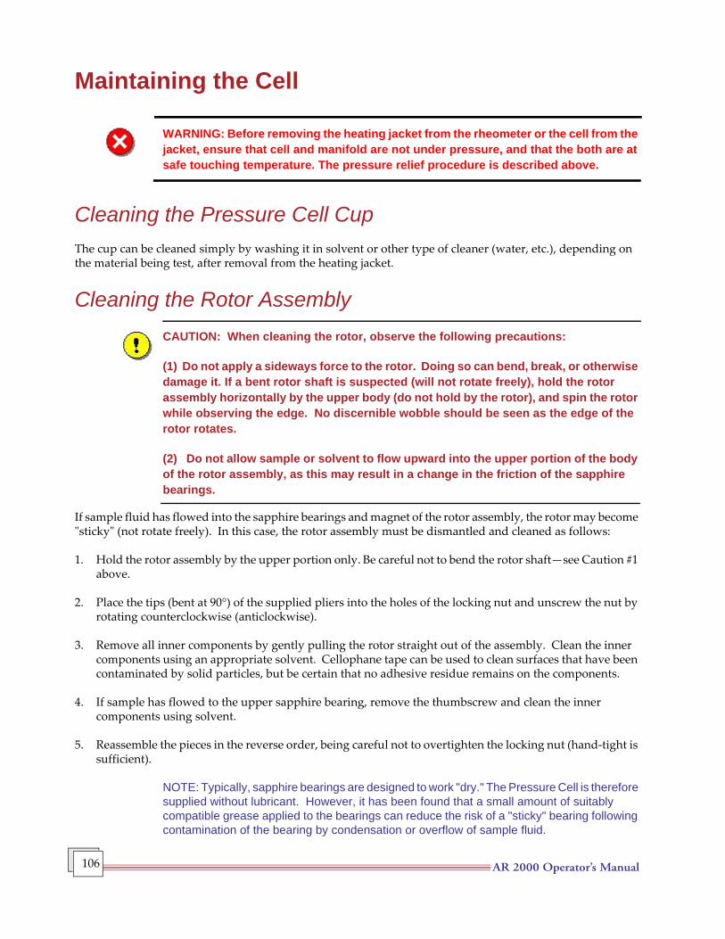
AR 2000 Operator’s Manual 106
Maintaining the Cell
WARNING: Before removing the heating jacket from the rheometer or the cell from the jacket, ensure that cell and manifold are not under pressure, and that the both are at safe touching temperature. The pressure relief procedure is described above.
Cleaning the Pressure Cell CupThe cup can be cleaned simply by washing it in solvent or other type of cleaner (water, etc.), depending on the material being test, after removal from the heating jacket.
Cleaning the Rotor AssemblyCAUTION: When cleaning the rotor, observe the following precautions:
(1) Do not apply a sideways force to the rotor. Doing so can bend, break, or otherwise damage it. If a bent rotor shaft is suspected (will not rotate freely), hold the rotor assembly horizontally by the upper body (do not hold by the rotor), and spin the rotor while observing the edge. No discernible wobble should be seen as the edge of the rotor rotates.
(2) Do not allow sample or solvent to flow upward into the upper portion of the body of the rotor assembly, as this may result in a change in the friction of the sapphire bearings.
If sample fluid has flowed into the sapphire bearings and magnet of the rotor assembly, the rotor may become "sticky" (not rotate freely). In this case, the rotor assembly must be dismantled and cleaned as follows:
1. Hold the rotor assembly by the upper portion only. Be careful not to bend the rotor shaft—see Caution #1 above.
2. Place the tips (bent at 90°) of the supplied pliers into the holes of the locking nut and unscrew the nut by rotating counterclockwise (anticlockwise).
3. Remove all inner components by gently pulling the rotor straight out of the assembly. Clean the inner components using an appropriate solvent. Cellophane tape can be used to clean surfaces that have been contaminated by solid particles, but be certain that no adhesive residue remains on the components.
4. If sample has flowed to the upper sapphire bearing, remove the thumbscrew and clean the inner components using solvent.
5. Reassemble the pieces in the reverse order, being careful not to overtighten the locking nut (hand-tight is sufficient).
NOTE: Typically, sapphire bearings are designed to work "dry." The Pressure Cell is therefore supplied without lubricant. However, it has been found that a small amount of suitably compatible grease applied to the bearings can reduce the risk of a "sticky" bearing following contamination of the bearing by condensation or overflow of sample fluid.
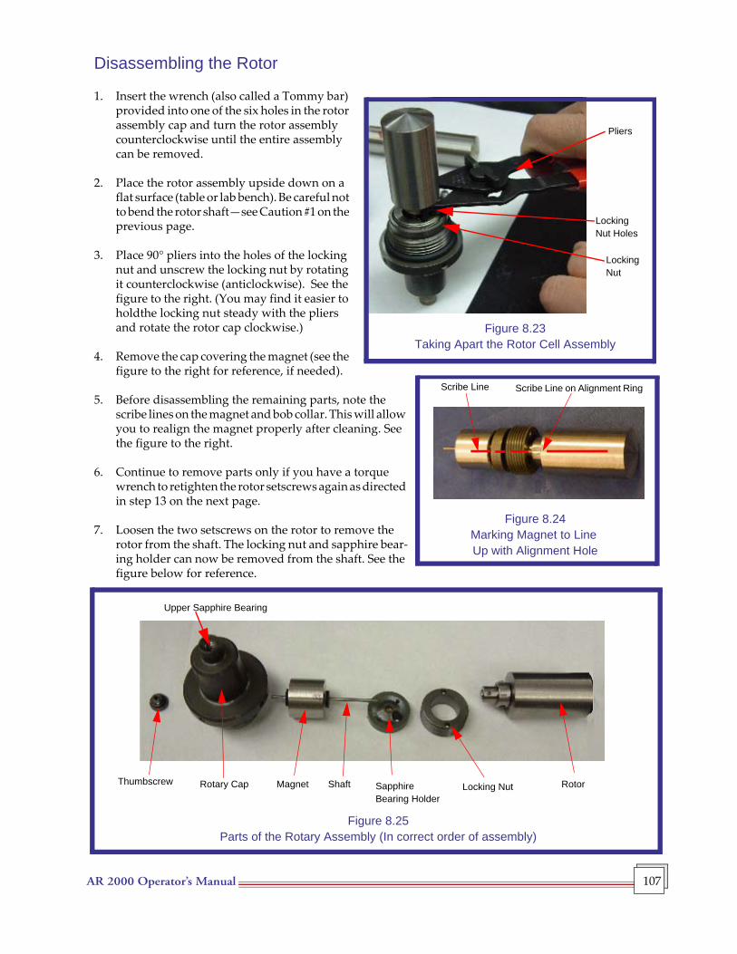
AR 2000 Operator’s Manual 107
Disassembling the Rotor
1. Insert the wrench (also called a Tommy bar) provided into one of the six holes in the rotor assembly cap and turn the rotor assembly counterclockwise until the entire assembly can be removed.
2. Place the rotor assembly upside down on a flat surface (table or lab bench). Be careful not to bend the rotor shaft—see Caution #1 on the previous page.
3. Place 90° pliers into the holes of the locking nut and unscrew the locking nut by rotating it counterclockwise (anticlockwise). See the figure to the right. (You may find it easier to holdthe locking nut steady with the pliers and rotate the rotor cap clockwise.)
4. Remove the cap covering the magnet (see the figure to the right for reference, if needed).
5. Before disassembling the remaining parts, note the scribe lines on the magnet and bob collar. This will allow you to realign the magnet properly after cleaning. See the figure to the right.
6. Continue to remove parts only if you have a torque wrench to retighten the rotor setscrews again as directed in step 13 on the next page.
7. Loosen the two setscrews on the rotor to remove the rotor from the shaft. The locking nut and sapphire bear-ing holder can now be removed from the shaft. See the figure below for reference.
Figure 8.24Marking Magnet to Line Up with Alignment Hole
Figure 8.23Taking Apart the Rotor Cell Assembly
Pliers
Locking Nut Holes
LockingNut
Scribe Line Scribe Line on Alignment Ring
Figure 8.25Parts of the Rotary Assembly (In correct order of assembly)
Thumbscrew Rotary Cap Magnet Shaft Sapphire Bearing Holder
RotorLocking Nut
Upper Sapphire Bearing
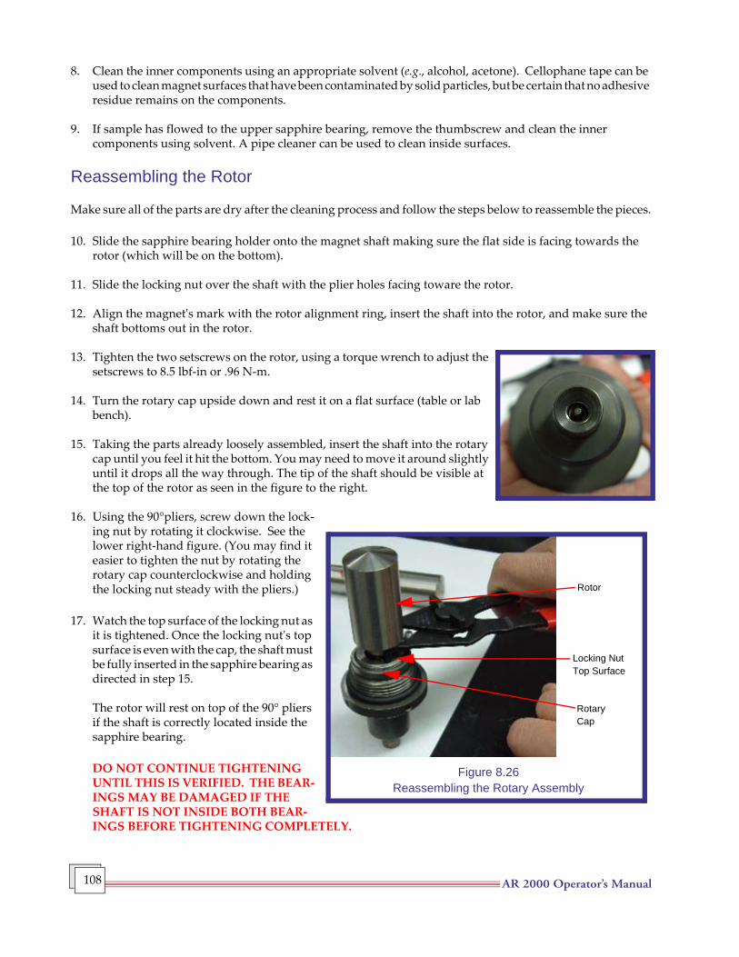
AR 2000 Operator’s Manual 108
8. Clean the inner components using an appropriate solvent (e.g., alcohol, acetone). Cellophane tape can be used to clean magnet surfaces that have been contaminated by solid particles, but be certain that no adhesive residue remains on the components.
9. If sample has flowed to the upper sapphire bearing, remove the thumbscrew and clean the inner components using solvent. A pipe cleaner can be used to clean inside surfaces.
Reassembling the Rotor
Make sure all of the parts are dry after the cleaning process and follow the steps below to reassemble the pieces.
10. Slide the sapphire bearing holder onto the magnet shaft making sure the flat side is facing towards the rotor (which will be on the bottom).
11. Slide the locking nut over the shaft with the plier holes facing toware the rotor.
12. Align the magnet's mark with the rotor alignment ring, insert the shaft into the rotor, and make sure the shaft bottoms out in the rotor.
13. Tighten the two setscrews on the rotor, using a torque wrench to adjust the setscrews to 8.5 lbf-in or .96 N-m.
14. Turn the rotary cap upside down and rest it on a flat surface (table or lab bench).
15. Taking the parts already loosely assembled, insert the shaft into the rotary cap until you feel it hit the bottom. You may need to move it around slightly until it drops all the way through. The tip of the shaft should be visible at the top of the rotor as seen in the figure to the right.
16. Using the 90°pliers, screw down the lock-ing nut by rotating it clockwise. See the lower right-hand figure. (You may find it easier to tighten the nut by rotating the rotary cap counterclockwise and holding the locking nut steady with the pliers.)
17. Watch the top surface of the locking nut as it is tightened. Once the locking nut's top surface is even with the cap, the shaft must be fully inserted in the sapphire bearing as directed in step 15.
The rotor will rest on top of the 90° pliers if the shaft is correctly located inside the sapphire bearing.
DO NOT CONTINUE TIGHTENING UNTIL THIS IS VERIFIED. THE BEAR-INGS MAY BE DAMAGED IF THE SHAFT IS NOT INSIDE BOTH BEAR-INGS BEFORE TIGHTENING COMPLETELY.
Figure 8.26Reassembling the Rotary Assembly
Rotor
Locking NutTop Surface
RotaryCap

AR 2000 Operator’s Manual 109
18. Replace the thumbscrew at the top of the rotary cap.
19. Turn the entire assembly right-side up and place it back into the pressure cell cup.
20. Insert the wrench (also called a Tommy bar) provided into one of the six holes in the rotor assembly cap and turn the rotor assembly clockwise threading it down and into the cup.
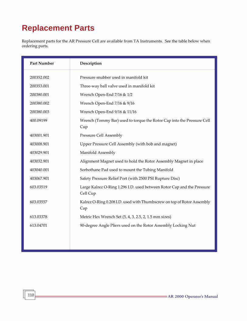
AR 2000 Operator’s Manual 110
Replacement PartsReplacement parts for the AR Pressure Cell are available from TA Instruments. See the table below when ordering parts.
Part Number Description
200352.002 Pressure snubber used in manifold kit
200353.001 Three-way ball valve used in manifold kit
200380.001 Wrench Open-End 7/16 & 1/2
200380.002 Wrench Open-End 7/16 & 9/16
200380.003 Wrench Open-End 9/16 & 11/16
400.09199 Wrench (Tommy Bar) used to torque the Rotor Cap into the Pressure Cell Cup
403001.901 Pressure Cell Assembly
403008.901 Upper Pressure Cell Assembly (with bob and magnet)
403029.901 Manifold Assembly
403032.901 Alignment Magnet used to hold the Rotor Assembly Magnet in place
403040.001 Sorbothane Pad used to mount the Tubing Manifold
403067.901 Safety Pressure Relief Port (with 2500 PSI Rupture Disc)
603.03519 Large Kalrez O-Ring 1.296 I.D. used between Rotor Cap and the Pressure Cell Cup
603.03557 Kalrez O-Ring 0.208 I.D. used with Thumbscrew on top of Rotor Assembly Cap
613.03378 Metric Hex Wrench Set (5, 4, 3, 2.5, 2, 1.5 mm sizes)
613.04701 90-degree Angle Pliers used on the Rotor Assembly Locking Nut
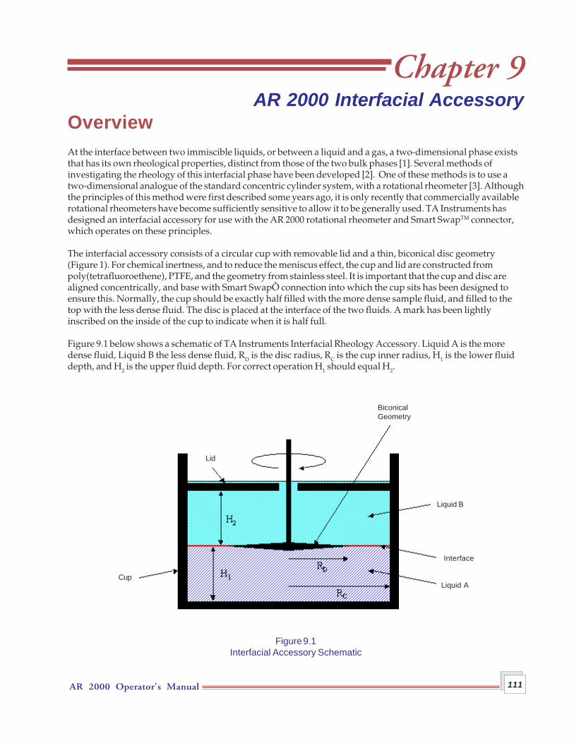
AR 2000 Operator's Manual 111
Chapter 9AR 2000 Interfacial Accessory
OverviewAt the interface between two immiscible liquids, or between a liquid and a gas, a two-dimensional phase existsthat has its own rheological properties, distinct from those of the two bulk phases [1]. Several methods ofinvestigating the rheology of this interfacial phase have been developed [2]. One of these methods is to use atwo-dimensional analogue of the standard concentric cylinder system, with a rotational rheometer [3]. Althoughthe principles of this method were first described some years ago, it is only recently that commercially availablerotational rheometers have become sufficiently sensitive to allow it to be generally used. TA Instruments hasdesigned an interfacial accessory for use with the AR 2000 rotational rheometer and Smart SwapTM connector,which operates on these principles.
The interfacial accessory consists of a circular cup with removable lid and a thin, biconical disc geometry(Figure 1). For chemical inertness, and to reduce the meniscus effect, the cup and lid are constructed frompoly(tetrafluoroethene), PTFE, and the geometry from stainless steel. It is important that the cup and disc arealigned concentrically, and base with Smart SwapÔ connection into which the cup sits has been designed toensure this. Normally, the cup should be exactly half filled with the more dense sample fluid, and filled to thetop with the less dense fluid. The disc is placed at the interface of the two fluids. A mark has been lightlyinscribed on the inside of the cup to indicate when it is half full.
Figure 9.1 below shows a schematic of TA Instruments Interfacial Rheology Accessory. Liquid A is the moredense fluid, Liquid B the less dense fluid, RD is the disc radius, RC is the cup inner radius, H1 is the lower fluiddepth, and H2 is the upper fluid depth. For correct operation H1 should equal H2.
Figure 9.1Interfacial Accessory Schematic
Cup
Lid
BiconicalGeometry
Liquid B
Interface
Liquid A
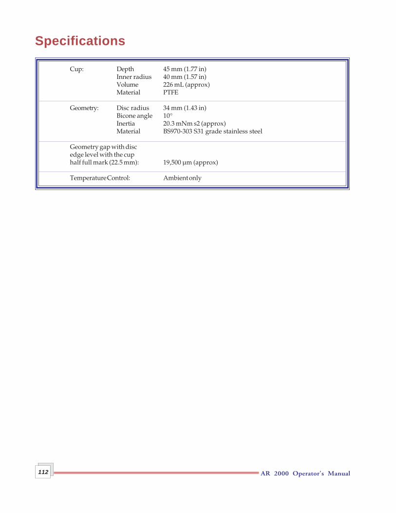
AR 2000 Operator's Manual112
Specifications
Cup: Depth 45 mm (1.77 in)Inner radius 40 mm (1.57 in)Volume 226 mL (approx)Material PTFE
Geometry: Disc radius 34 mm (1.43 in)Bicone angle 10°Inertia 20.3 mNm s2 (approx)Material BS970-303 S31 grade stainless steel
Geometry gap with discedge level with the cuphalf full mark (22.5 mm): 19,500 µm (approx)
Temperature Control: Ambient only
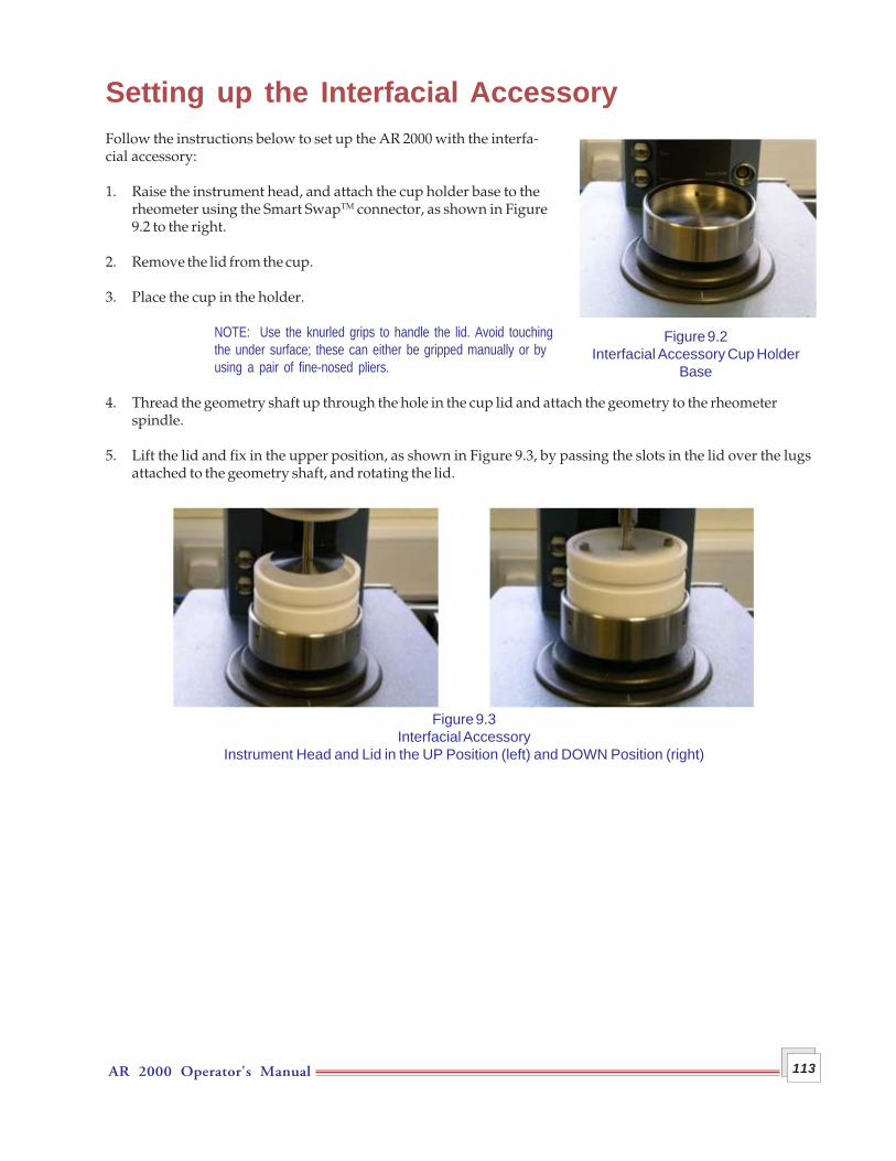
AR 2000 Operator's Manual 113
Setting up the Interfacial AccessoryFollow the instructions below to set up the AR 2000 with the interfa-cial accessory:
1. Raise the instrument head, and attach the cup holder base to therheometer using the Smart SwapTM connector, as shown in Figure9.2 to the right.
2. Remove the lid from the cup.
3. Place the cup in the holder.
NOTE: Use the knurled grips to handle the lid. Avoid touchingthe under surface; these can either be gripped manually or byusing a pair of fine-nosed pliers.
4. Thread the geometry shaft up through the hole in the cup lid and attach the geometry to the rheometerspindle.
5. Lift the lid and fix in the upper position, as shown in Figure 9.3, by passing the slots in the lid over the lugsattached to the geometry shaft, and rotating the lid.
Figure 9.2Interfacial Accessory Cup Holder
Base
Figure 9.3Interfacial Accessory
Instrument Head and Lid in the UP Position (left) and DOWN Position (right)
AR 2000 Operator's Manual114
Calibration and MappingZeroing the GapFollow these steps to zero the gap:
1. Lower the instrument head until the bicone is within the cup, but is clear of the cup lower surface.
2. Lower the lid to sit in the groove on top of the cup as shown in Figure 9.3 on the previous page.
3. Zero the geometry gap in the usual way.
NOTE: At the zero position, the lugs on the geometry shaft will be approximately 2 mm clear of the lid.
Mapping and Other CalibrationsMapping and other calibrations (such as for geometry inertia and bearing friction), are best carried out at thisstage. Set a gap of 19500 µm, and perform the mapping and calibrations in the usual way.
AR 2000 Operator's Manual 115
Experimental ProcedureThe calculation of the interfacial viscosity for the general case described previously is complicated, and can onlybe solved using numerical procedures [2]. However, if the first order assumption is made that the contributionsfrom the three phases are independent of each other, the calculation becomes relatively straightforward. Thecontributions from each of the two bulk fluids can be obtained separately and the interfacial contribution can beobtained by subtraction of these from the total contribution.
• For this procedure, the cup is filled completely with one of the fluids and the geometry is set to gap of19,500 µm, so that the disc edge is level with the half full mark.
• The instrument torque is determined over the range of angular velocities (or shear rates) of interest.
• The process is repeated for the other fluid, and the contributions to the torque from each fluid at eachangular velocity are added.
This total will be twice that of the upper and lower fluids combined when they each occupy half the cupvolume, and can therefore be halved and subtracted from the total torque, obtained in the presence of theinterface, to give the contribution due to the interface. A two-dimensional analog of the concentric cylindergeometry is used to give the interfacial viscosity. Details of the analysis are given below.
Determining Each Fluid's ContributionFollow the steps below to determine the contribution from each bulk fluid.
1. Make sure the gap is set at 19500 µm.
2. Fill the cup with Sample Fluid A, until the fluid just reaches the lower edge of the groove on top of the cup.
3. Gently lower the lid. The fluid should overflow from the annular gap between the lid and the geometry.
4. Use a Flow procedure to apply the required angular velocity (or shear rate) or range of velocities. Alterna-tively, apply the required torque or range of torques. It is usually preferable to use a Steady State Flowprocedure for this, but the details will depend on the sample, and the reasons for conducting the experi-ment. This procedure gives the torque contribution of Fluid A, MAcalibration(Ω), at angular velocity Ω.
NOTE: When setting up the procedure, in the Conditioning step on the Settings tab, uncheck the "Wait forcorrect temperature" box. Any temperature settings in the procedure will be ignored.
5. After running the procedure, raise the instrument head.
6. Remove, clean and replace the cup.
7. Repeat the procedure for the Sample Fluid B, to obtain MBcalibration(Ω) then remove, clean and replace thecup.
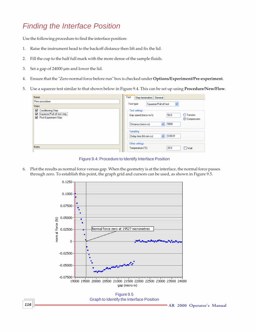
AR 2000 Operator's Manual116
Finding the Interface PositionUse the following procedure to find the interface position:
1. Raise the instrument head to the backoff distance then lift and fix the lid.
2. Fill the cup to the half full mark with the more dense of the sample fluids.
3. Set a gap of 24000 µm and lower the lid.
4. Ensure that the "Zero normal force before run" box is checked under Options/Experiment/Pre-experiment.
5. Use a squeeze test similar to that shown below in Figure 9.4. This can be set up using Procedure/New/Flow.
Figure 9.4: Procedure to Identify Interface Position
6. Plot the results as normal force versus gap. When the geometry is at the interface, the normal force passesthrough zero. To establish this point, the graph grid and cursors can be used, as shown in Figure 9.5.
Figure 9.5Graph to Identify the Interface Position
AR 2000 Operator's Manual 117
7. Determine the point at which the normal force passes through zero. This is the position of the interface,which should be at a gap of approximately 19500 µm. Adjust the fluid volume to obtain this gap. Keep inmind that 1 mL of fluid changes the level by about 0.275 mm.
8. When the interfacial position has been identified, manually set the gap to that position (in the exampleshown on the previous page, to 19527 µm).
9. Lift and fix the lid. You may find it convenient at this stage to add any surfactants to be used.
10. After addition of surfactant, gently add the less dense fluid until the lower edge of the groove on the top ofthe cup is just covered, then lower the lid gently. The upper fluid should just enter the annular gap betweenthe lid and the geometry shaft. The viscosity of the total system including the interface can now be mea-sured.
11. Run the Flow procedure used to determine the contributions of the two bulk fluids, described above, toobtain the total torque Mtotal(Ω).
AR 2000 Operator's Manual118
Analyzing the ResultsCalculation of the Interfacial Contribution to the TorqueThe interfacial contribution to the torque, Minterfacial(Ω) at a particular angular velocity is calculated by subtract-ing the contributions of the two bulk fluids, A and B from the total torque for the system at that angular velocity,i.e.:
Mtotal(Ω) = Minterfacial(Ω) + MA(Ω) + MB(Ω)
MA and MB, are obtained from the calibration routine described above. But MA(Ω) is half the torque obtained atΩ for Fluid A from the calibration routine, and MB is half that obtained for Fluid B, since for the calibrationroutines the cell is filled with the relevant fluid, whereas for the interfacial measurement it is half filled withFluid A and half with Fluid B, i.e.:
MA(Ω) = MAcalibration(Ω) / 2 and MB(Ω) = MBcalibration(Ω) / 2
Three data points are therefore needed for each angular velocity used:
• the calibration data point for Fluid A• the calibration data point for Fluid B• the data point for the total system
Then:
Minterfacial(Ω) = Mtotal(Ω) - [(MAcalibration(Ω) / 2) + (MBcalibration(Ω) / 2)]
Minterfacial(Ω) = Mtotal(Ω) - [MAcalibration(Ω) + (MBcalibration(Ω)] / 2
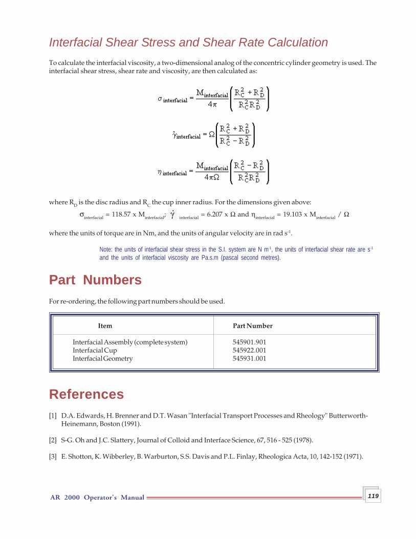
AR 2000 Operator's Manual 119
Interfacial Shear Stress and Shear Rate CalculationTo calculate the interfacial viscosity, a two-dimensional analog of the concentric cylinder geometry is used. Theinterfacial shear stress, shear rate and viscosity, are then calculated as:
where RD is the disc radius and RC the cup inner radius. For the dimensions given above:
σinterfacial = 118.57 x Minterfacial; interfacial = 6.207 x Ω and ηinterfacial = 19.103 x Minterfacial / Ω
where the units of torque are in Nm, and the units of angular velocity are in rad s-1.
Note: the units of interfacial shear stress in the S.I. system are N m-1, the units of interfacial shear rate are s-1
and the units of interfacial viscosity are Pa.s.m (pascal second metres).
Part NumbersFor re-ordering, the following part numbers should be used.
Item Part Number
Interfacial Assembly (complete system) 545901.901Interfacial Cup 545922.001Interfacial Geometry 545931.001
References[1] D.A. Edwards, H. Brenner and D.T. Wasan "Interfacial Transport Processes and Rheology" Butterworth-
Heinemann, Boston (1991).
[2] S-G. Oh and J.C. Slattery, Journal of Colloid and Interface Science, 67, 516 - 525 (1978).
[3] E. Shotton, K. Wibberley, B. Warburton, S.S. Davis and P.L. Finlay, Rheologica Acta, 10, 142-152 (1971).

AR 2000 Operator's Manual120
AR 2000 Operator's Manual 121
Chapter 10Do's and Don'ts
OverviewPlease read this chapter thoroughly before using your rheometer. It may be helpful to prepare a copy of thesepoints and place them in a prominent position near the instrument.
DO... ensure the air supply is always very clean at a stable pressure. A coarse filter and desiccant dryer system
and double filter regulator assembly should be used.
... look out for water collection in the filter bowls before and during use of the instrument. Drain the filterbowls whenever necessary. (See Chapter 5.)
... look for visible signs of dirt on the filter elements in the filter regulator before use. Replace whenevernecessary.
... replace the air-bearing clamp when the air in ON, and always ensure it is in place when the instrument ismoved or when the air is switched off.
... refit the air connector plug supplied with the instrument whenever the air line is disconnected.
... disconnect and blast air through the air line whenever starting up after any period which air has beenswitched off. (Not necessary every morning, unless you know your air supply tends to accumulate waterovernight.)
... connect and switch on air supply before switching the instrument on.
... switch on water supply to the Peltier plate before switching the instrument on.
... use good laboratory practice when using the instrument. Wear safety glasses and protective clothingwhere necessary.
AR 2000 Operator's Manual122
DON'T... operate the instrument without the correct air supply.
... remove the air connector plug until ready to attach purged air supply.
... unnecessarily touch the air-bearing spindle unless the air is on. This includes attaching and removinggeometries.
... use the rheometer head as a lifting point.
... operate the instrument without a water supply if you have a Peltier System.
... disconnect or connect any cables, leads etc. while the power is on.
... be frightened of using the instrument for the first time.
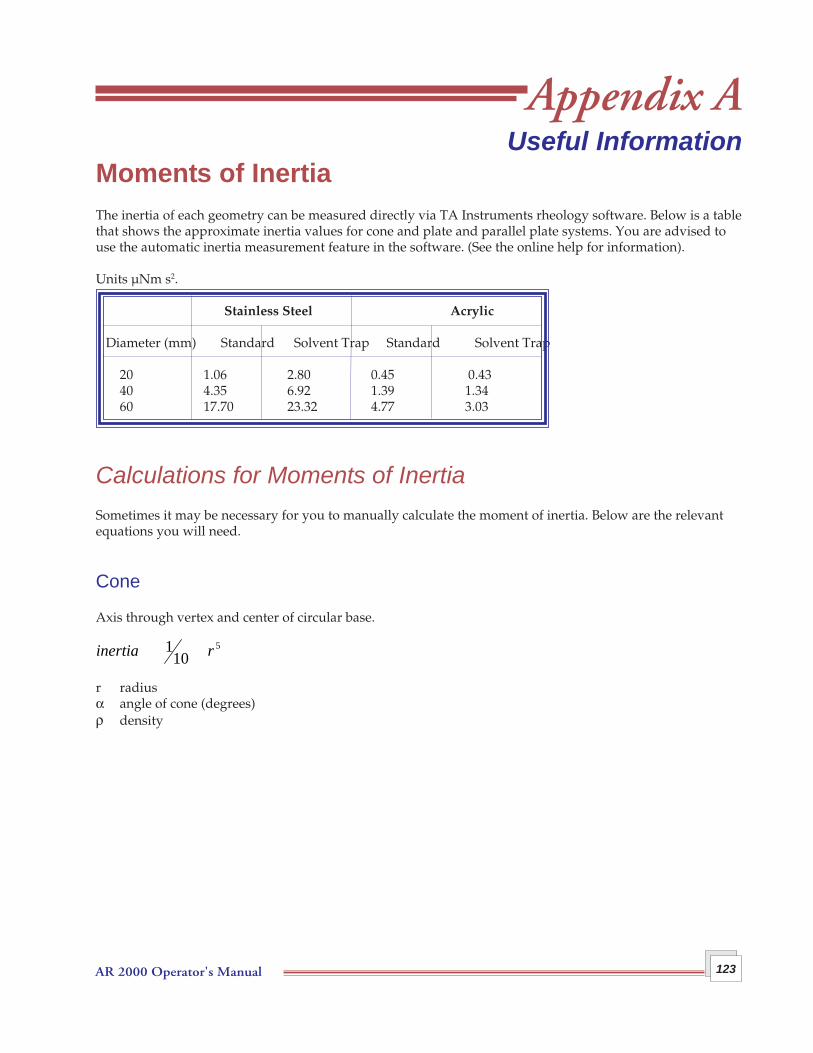
AR 2000 Operator's Manual 123
Appendix AUseful Information
Moments of InertiaThe inertia of each geometry can be measured directly via TA Instruments rheology software. Below is a tablethat shows the approximate inertia values for cone and plate and parallel plate systems. You are advised touse the automatic inertia measurement feature in the software. (See the online help for information).
Units µNm s2.
Stainless Steel Acrylic
Diameter (mm) Standard Solvent Trap Standard Solvent Trap
20 1.06 2.80 0.45 0.4340 4.35 6.92 1.39 1.3460 17.70 23.32 4.77 3.03
Calculations for Moments of InertiaSometimes it may be necessary for you to manually calculate the moment of inertia. Below are the relevantequations you will need.
Cone
Axis through vertex and center of circular base.
r radiusα angle of cone (degrees)ρ density
inertia r 110
5
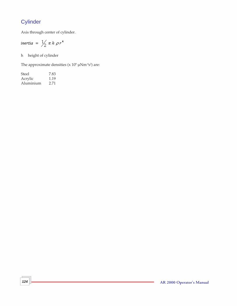
AR 2000 Operator's Manual124
Cylinder
Axis through center of cylinder.
h height of cylinder
The approximate densities (x 109 µNm-4s2) are:
Steel 7.83Acrylic 1.19Aluminium 2.71
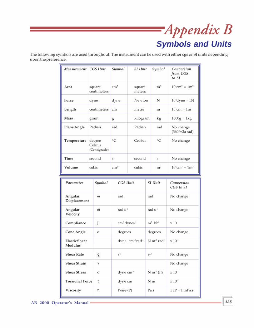
AR 2000 Operator's Manual 125
Appendix BSymbols and Units
The following symbols are used throughout. The instrument can be used with either cgs or SI units dependingupon the preference.
Parameter Symbol CGS Unit SI Unit ConversionCGS to SI
Angular ω rad rad No changeDisplacement
Angular ϖ rad s-1 rad s-1 No changeVelocity
Compliance J cm2 dynes-1 m2 N-1 x 10
Cone Angle α degrees degrees No change
Elastic Shear dyne cm−2rad−1 N m-2 rad-1 x 10⁻¹
Modulus
Shear Rate g s-1 s-1 No change
Shear Strain γ No change
Shear Stress σ dyne cm-2 N m-2 (Pa) x 10-1
Torsional Force τ dyne cm N m x 10-7
Viscosity η Poise (P) Pa.s 1 cP = 1 mPa.s
Measurement CGS Unit Symbol SI Unit Symbol Conversionfrom CGSto SI
Area square cm2 square m2 104cm2 = 1m2
centimeters meters
Force dyne dyne Newton N 105dyne = 1N
Length centimeters cm meter m 102cm = 1m
Mass gram g kilogram kg 1000g = 1kg
Plane Angle Radian rad Radian rad No change(360°=2π rad)
Temperature degree °C Celsius °C No changeCelsius(Centigrade)
Time second s second s No change
Volume cubic cm3 cubic m3 106cm3 = 1m3

AR 2000 Operator's Manual126
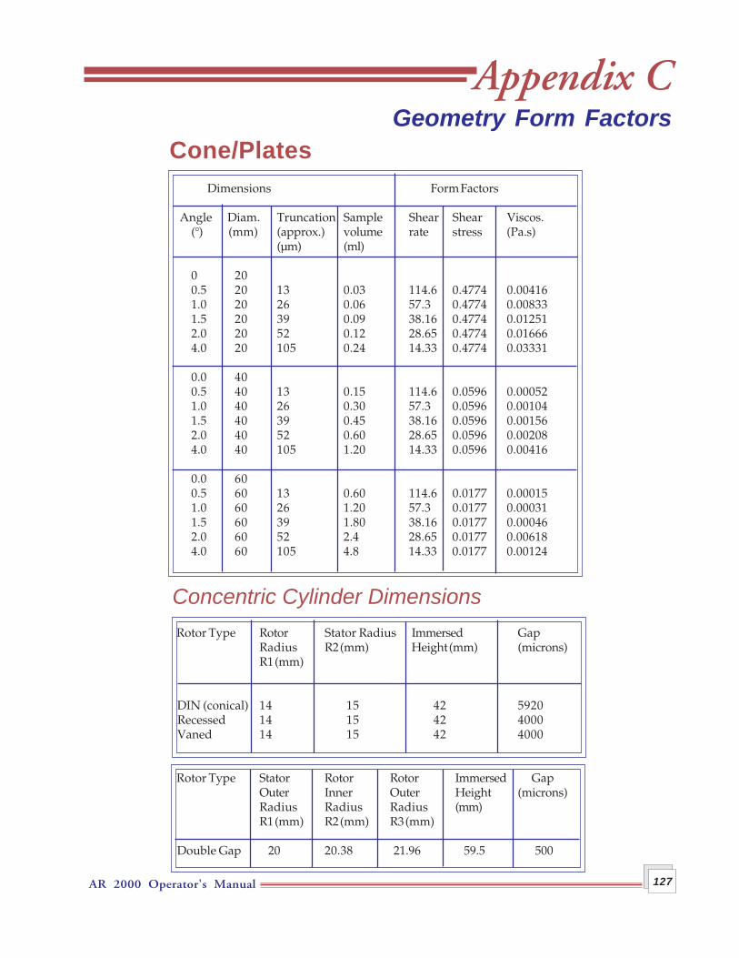
AR 2000 Operator's Manual 127
Appendix CGeometry Form Factors
Cone/Plates Dimensions Form Factors
Angle Diam. Truncation Sample Shear Shear Viscos.(°) (mm) (approx.) volume rate stress (Pa.s)
(µm) (ml)
0 200.5 20 13 0.03 114.6 0.4774 0.004161.0 20 26 0.06 57.3 0.4774 0.008331.5 20 39 0.09 38.16 0.4774 0.012512.0 20 52 0.12 28.65 0.4774 0.016664.0 20 105 0.24 14.33 0.4774 0.03331
0.0 400.5 40 13 0.15 114.6 0.0596 0.000521.0 40 26 0.30 57.3 0.0596 0.001041.5 40 39 0.45 38.16 0.0596 0.001562.0 40 52 0.60 28.65 0.0596 0.002084.0 40 105 1.20 14.33 0.0596 0.00416
0.0 600.5 60 13 0.60 114.6 0.0177 0.000151.0 60 26 1.20 57.3 0.0177 0.000311.5 60 39 1.80 38.16 0.0177 0.000462.0 60 52 2.4 28.65 0.0177 0.006184.0 60 105 4.8 14.33 0.0177 0.00124
Concentric Cylinder Dimensions Rotor Type Rotor Stator Radius Immersed Gap
Radius R2 (mm) Height (mm) (microns)R1 (mm)
DIN (conical) 14 15 42 5920 Recessed 14 15 42 4000 Vaned 14 15 42 4000
Rotor Type Stator Rotor Rotor Immersed GapOuter Inner Outer Height (microns)Radius Radius Radius (mm)R1 (mm) R2 (mm) R3 (mm)
Double Gap 20 20.38 21.96 59.5 500

AR 2000 Operator's Manual128
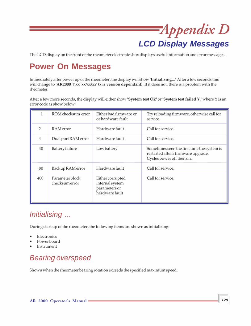
AR 2000 Operator's Manual 129
The LCD display on the front of the rheometer electronics box displays useful information and error messages.
Power On MessagesImmediately after power up of the rheometer, the display will show 'Initialising...' After a few seconds thiswill change to 'AR2000 7.xx xx/xx/xx' (x is version dependant). If it does not, there is a problem with therheometer.
After a few more seconds, the display will either show 'System test Ok' or 'System test failed Y,' where Y is anerror code as show below:
1 ROM checksum error Either bad firmware or Try reloading firmware, otherwise call foror hardware fault service.
2 RAM error Hardware fault Call for service.
4 Dual port RAM error Hardware fault Call for service.
40 Battery failure Low battery Sometimes seen the first time the system isrestarted after a firmware upgrade.Cycles power off then on.
80 Backup RAM error Hardware fault Call for service.
400 Parameter block Either corrupted Call for service.checksum error internal system
parameters orhardware fault
Initialising ...During start up of the rheometer, the following items are shown as initializing:
• Electronics• Power board• Instrument
Bearing overspeedShown when the rheometer bearing rotation exceeds the specified maximum speed.
Appendix DLCD Display Messages
AR 2000 Operator's Manual130
Bearing pressure too lowThis is displayed if the air supply has been inadvertently switched off while the rheometer was on or if thesupply pressure has dropped below the minimum operating pressure.
Encoder index not foundThis message can be displayed if the air bearing is not free to move. This can occur if the air-bearing clamp isstill attached or if the air bearing lock is on. Failing this, there may be a fault on the position encoder.
Nf gauge faultThis message is displayed if an excessive normal force was detected when attempting to zero the normal forcereading. This could be caused by either an excessive force being applied by air bearing/sample/mechanicalinterference with ETC or a gauge fault.
Nf temp sensor faultThis message is displayed if there are either faulty normal force temp sensors or, if you have for instance, frozenthe instrument with excessive liquid nitrogen.
Operator stop eventThis message is displayed when the Stop button was pressed while the Rheology Advantage software had thekeypad locked. This usually indicates that a test run was in progress and the operator aborted it using therheometer stop button.
Power cable faultThis indicates that the Power cable may not be plugged in firmly. See Chapter 5 for connection information.
Signal cable faultThis message indicates that the signal cable may not be plugged in firmly. See Chapter 5 for connection infor-mation.
Temp sys element faultThis message is displayed because the Peltier or heater element has developed a fault.
Temp system environmentThere is a configuration problem with the installed temperature control module. I.e., no water to the Peltier etc.Re-read the manual to check you have set everything up correctly.

AR 2000 Operator's Manual 131
Temp system sensor faultThis message is likely caused by fault/damage to the Pt100 or thermocouple.
Other MessagesOther error messages may be displayed. These are usually indicative of problems with the rheometer that canonly be fixed by a qualified TA Instruments representative.

AR 2000 Operator's Manual132

AR 2000 Operator's Manual 133
ETC Torsion Rectangular Kit (543307.901)Item No. Description Quantity1 Lower Clamp Assembly 12 Upper shaft 13 Clamp set rectangular 14 Torque wrench 15 Digital Callipers 16 Tommy Bar 17 0.25 mm spacers 28 0.5 mm spacers 29 0.75 mm spacers 210 Compliance Standard 111 ABS polymer samples 10
ETC Parallel Plate Kit (543306.901)Item No. Description Quantity1 Lower Plate Assembly 12 Upper Shaft 13 25 mm Parallel plates 1 set4 40 mm Parallel plates 1 set5 Melt Ring 106 Tommy Bar 17 Brass brush 18 Brass scraper 1
ETC Disp. Parallel Plate Kit (543308.901)Item No. Description Quantity1 Lower Plate Assembly 12 Upper Shaft 13 25 mm Parallel disposable plates 10 set4 Tommy Bar 15 Hex key6 Spare clamping screws
Appendix ETA Instruments ETC Kits

AR 2000 Operator's Manual134
AR 2000 Operator's Manual 135
Index
Aair bearing 25 to 26
air-bearing clamp 35removing 63Upper Heated Plate (UHP) 81
anglescones 60
AR 2000 Rheometeradditional precautions 47air bearing 25changing the cup 42checking system 52components 23connecting the purge gas 45connecting to electronics control box 37cooling 49description 11dimensions 31do's and don'ts 121electronics 23error codes 129flow rate 28geometries 55installation requirements 36internal fuse 36keypad 51LCD display messages 129lifting and carrying 17location requirements 36normal force transducer 29preparing for installation 35preventing slippage at sample/geometry interface 62removing packaging 35repair 20schematics 22technical descriptions 25technical specifications 31, 32temperature control 28thermocouple 48using the stress and shear rate factors 59water bath 28
AR 2000 Operator's Manual136
Auto GapSet 27
auto-zero gap 51
Bbattery
lithium 11
Ccables
connecting 39
calibration 53Upper Heated Plate (UHP) 78
chemical safety 19
cleaningfilter regulator assembly 54
computerconnecting to electronics control box 37
concentric cylinder systems 58conical end 58double concentric 59form factors 127recessed end 58setting up 41
cone and plate system 56, 60angles 60material 61moments of inertia 123
cone and plate systemsform factors 127
controlled-stress technique 22
coolingcontrolled 49
Cooling Control Unit (CCU) 67
cross threading 50
AR 2000 Operator's Manual 137
cross-hatched geometries 62
cryogenic pressure vessel 49
cupchanging 42
Ddeformation 22
desiccant dryer system 121
diameterscones 60
draw rod 35, 55
drive motor 23
Eedge effects 65
electrical safety 17
electronic control box 49
EMC Conformité 16
EMC Conformity 15
encoder disc 23
Environmental Test Chamber (ETC)specifications 32
Environmental Testing Chamber. See ETC. See also ETC
Environmental Testing Chamber (ETC)installing 43installing the low temperature accessory 46internal components 11kits 133oven 43setting up 43
equilibrium time 49
AR 2000 Operator's Manual138
error codes 129
EVENT socket 75
Ffilter regulator assembly
cleaning 54signs of dirt 121
flow rate 28, 46
fluid cablesconnecting 39
fluidsused with the Upper Heated Plate (UHP) 74
fuse 36
Ggap
closing 27overfilling 65setting 57underfilling 65zeroing 27
gap zeroing 27
geometries 47
geometry. See also measuring systemaluminum 55attaching 64choosing the best 60concentric cylinders 58cone and plate 56connecting for Upper Heated Plate 76cross-hatched 62description 55disconnecting for Upper Heated Plate 76form factors 127intertia 123materials 55 to 60parallel plate 57plastic 56solvent trap version 62stainless steel 55
AR 2000 Operator's Manual 139
Iinert gas 82
installationrequirements 36
Interfacial Accessoryanalyzing results 118calibrating 114description 111determining interface position 116experimental procedure 115installation 113interface position
determining 116introduction 111mapping 114ordering parts 119procedures used with 115references 119set up 113shear rate 119shear stress 119specifications 112torque 115using during experiments 115viscosity 119viscosity measurement 117zeroing the gap 114
Llab air 36
l'azote liquide 18
LCD display messages 129
levelling 52
lifting and carrying 17
liquid nitrogen 12handling 19safety 18
lithium battery 11
AR 2000 Operator's Manual140
location 36
low temperature accessory 46
Mmapping procedure 49
measurementspreventing evaporation 62
measuring systemgeneral description 55
microprocessor 26
moments of inertiacalculation 123 to 124
motor spindle 55
NNewtonian viscosity 53
normal force transducer 29
Notes, Cautions, and Warnings 10
Ooperation
general guidelines 50rheometer 49
optical encoder 26
Ppackaging
removing 35
parallel plate system 57moments of inertia 123
parallel plate systems 60
AR 2000 Operator's Manual 141
parallel plates 47cleaning 48
Peltier Concentric Cylinder Systemspecifications 33
Peltier Plate 28 to 29installing 39removing 40
Peltier plate 55
Peltier Plate Systemspecifications 32
Peltier plate system 121
polymers 49
power cables 12connecting 39
power outlet 36
pressure 46
Pressure Cellaligning manifold 100cleaning the cup 106cleaning the rotor assembly 106components 87Concentric Cylinder rotor 89cup 88disassembling rotor 107gauge port 88inlet port 88installation 94installation of cup and rotor 95installation of manifold 94introduction 85loading a sample 98magnet assembly 90maintenance 106manifold 91operational limits 86positioning gap 97pressurizing 101reassembling rotor 108replacement parts 110requirements for external pressure source 92rotor assembly 89
AR 2000 Operator's Manual142
running experiments in external pressurization mode 104running experiments in self-pressurization mode 102safety relief port 89safety specifications 86specifications 86three-way valve 101purge gasconnecting to rheometer 45
Rrelative humidity 36
rheologydefinition 22
rheometersbrief history 21
Rotational Mapping 26, 26 to 27
Rotor 55
Ssafety
chemical 19electrical 17EMC Conformity 15warnings 11
sampleloading 65
sample cover 83
samplespreventing evaporation 62
shear rate 59
shear stress 59
shut down 53
Sir Isaac Newton 21
Smart Swap™ 28using 39
Pressure Cell (con'td)
AR 2000 Operator's Manual 143
Smart Swap Peltier plate 67
solventspreventing evaporation 62
specifications 31AR 2000 31ETC 32Peltier concentric cylinder system 33Peltier plate system 32
Stator 55
strain 59
symbols 125
system check 52
Tthermal compensation 27 to 29
thermocouple 48
Uunits 125
Upper Heated Plate (UHP)air-bearing clamp 81attaching to rheometer 68calibrating 78circulating fluids 74configuring 77connecting the Cooling Control Unit (CCU) 73connection configurations 72cooling water 72description 67gas atmosphere 67, 82geometry holder
disconnecting 76introduction 67modeling enabled 77Pt100 67sample cover 83using inert gas atmosphere 82zero heat flow sensor 80zero value plug 79
AR 2000 Operator's Manual144
Vviscosity
definition 21
Wwarnings
important information 11
waterconnecting to rheometer 38
water bath 28
work surface 36
ZZero Gap 51
zero heat flow sensorUpper Heated Plate (UHP) 80