Embed Size (px)
Citation preview

AQUIS ULTRAFLOW—Tellurus HMIInstallation and Operation
Form Number: F2925 Issue Date: Jun 29, 2021Revision Date: Nov 12, 2021
Waterous Company • 125 Hardman Avenue South • South Saint Paul, MN 55075 • (651) 450-5000www.waterousco.com


Table of ContentsSafety 4
Safety Precautions 4
Introduction 5Using this Document 5
Viewing the Document Electronically 5Printing the Document 5
Product Overview 6AQUIS ULTRAFLOW Industrial Foam Proportioner System 6HMI and Components 1015-Inch Tellurus HMI 128-Inch Tellurus HMI 14WiFi and GPS Antenna 16HMI Cable 18HMI M12 Cable 192.0 Meter CANbus Extension Cable 200.5 Meter CANbus Extension Cable 21
Installation 22Installation Overview 22Preparing for the Installation 22Modifying the Equipment 22Additional Documentation 22Optional Equipment 22Determining Panel and Plate Locations 23Determining Cable and Wire Routing 23HMI Cables and Connections 24Connecting the Tellurus Display 26Configuring the System 27Desktop Icons 29Desktop Icons—Operation Menu 30Desktop Icons—Customer Service Menu 31Desktop Icons—Configuration Menu 32Desktop Icons—Maintenance Menu 33Using the Live Troubleshooting App 34
Remote Connection Icon 36Calibrating the Touch Screen 37
Calibrate Touch Icon 37Command Interface Menu 38
Operation 39Powering Up the Display 39HMI Display—Screen Size 40HMI Display—Orb Button 41DLA Gauge Screen 42Solution Screen—Buttons 43Solution Screen—Telemetry 44Solution Screen—Concentrate Gauge 45Solution Screen—Water Gauge 46System Screen—Buttons 47System Screen—Telemetry 48Enabling and Disabling a DLA—Screen Views 49Adjusting the Solution Screen 51Switching the Concentrate Source—Screen View 52Refilling the On-Board Supply Tank—Screen View 54Relaying Concentrate 56Manually Priming the Concentrate Line 57Transferring Concentrate 58Verifying Concentrate Output with Water 59
Preparing for Validation 59Verifying Concentrate Output with Water 60
Operating Simulated Flow Mode 60
Maintenance 61Maintenance Schedule 61

4 | 62
Safety Introduction Product Overview Installation Operation Maintenance
Safety Precautions• Read and understand all the associated documentation before you begin the
installation.• Read and understand all the notices and safety precautions.• Be aware that these instructions are only guidelines and are not meant to be
definitive. Contact Waterous when you have questions about installing, operating, or maintaining the equipment.
• Do not install the equipment if you are not familiar with the tools and skills needed to safely perform the required procedures—proper installation is the responsibility of the purchaser.
• Do not operate the equipment when safety guards are removed.• Do not modify the equipment.• Regularly check for leaks and worn or deteriorated parts.
NOTICEModifying the equipmentcan damage componentsand void your warranty.
•
Do not modify the systemor any of its components.
•
Modification
NOTICEBefore Operation
• Read and understand all the instructions provided.• Check all fluid levels and replenish if necessary.• Remove all shipping plugs and install the operation plugs or caps.

5 | 62
Safety Introduction Product Overview Installation Operation Maintenance
Use this document to install and operate your Waterous equipment. Understand the following conditions before continuing with the document:• The instructions may refer to options or equipment that you may not have
purchased with your system.• The illustrations in this document are intended to convey concepts. Do not
use the illustrations to determine physical attributes, placement, or proportion.
• Understand that your application may require additional steps, that are not described in the illustrations or instructions, to perform the installation.
• The equipment described in this document is intended to be installed by a person or persons with the necessary skills and knowledge to perform the installation.
• The equipment described in this document is intended to be operated by a person or persons with the basic knowledge of operating similar equipment.
• The information in this document is subject to change without notice.
This document is divided into the following sections:Safety
This section describes general precautions and alert symbols that are in this document.Introduction
This section is an overview of the document.Product Overview
This section describes the components that make-up the system.Installation
This section describes the installation and initial setup procedures.Operation
This section describes the equipment operation.Maintenance
This section describes any required maintenance.
Using this DocumentUse the guidelines below when viewing this document.
Viewing the Document Electronically• View this document in landscape orientation.• Use the table of contents to navigate directly to that section.• Text with this appearance is linked to a reference.
Printing the Document• The document is viewed the best when printed in color.• The print on both sides and flip on long edge features can provide the
best results.• Use a 3-ring binder to store the document.

6 | 62
Safety Introduction Product Overview Installation Operation Maintenance
AQUIS ULTRAFLOW Industrial Foam Proportioner System
1
4
5
3 2
99
8
7
6

7 | 62
Safety Introduction Product Overview Installation Operation Maintenance
AQUIS ULTRAFLOW Industrial Foam Proportioner SystemThe AQUIS ULTRAFLOW industrial foam proportioner system supplies concentrate into a solution-capable discharge line. A Tellurus™ touchscreen display, or human machine interface (HMI), shows system activity, and provides control over the system using a CANbus protocol. Foam concentrate is sourced from an on-board supply tank or an auxiliary source. The concentrate pump distributes concentrate though the discharge line assembly (DLA) using hydraulic components, where it is measured, controlled, and introduced into the solution-capable discharge line to produce foam solution. Understand that your application will include all or portions of the components described.
SubsystemSubsystem DescriptionDescription1 Control system This monitors and controls the foam proportioning system. The components in this subsystem include:
• Tellurus display (HMI)—this displays system operation and provides control of the system.• Control box—this connects to various components in the system and contains the programmable logic controllers (PLC).• Manual override switch—this disables the automatic control of the concentrate control valves.• Power disconnect relay—this power relay enables and disables power to the DLA.• Remote I/O—this adds a node controller to the system for additional options required in your application.• Various cables—these provide communication and power to system components.
2 Discharge line assembly This manages the concentrate injected into the solution-capable discharge. The system can control up to 19 DLAs. The components in this subsystem include:• Node controller—this connects to, and controls, the concentrate control valve, reads the flowmeters and the discharge
pressure transducer.• Split CANbus cable—this connects the node controllers to one another and the control box.• DLA terminating resistor—this terminates the CANbus connection on the last node controller or valve in the CANbus
chain.• Concentrate control valve—this controls the concentrate flow.• Magnetic flowmeter—this measures the concentrate flow.• Check valve—this prevents contamination of concentrate by preventing reverse fluid flow in the line.• Cal/Inject valve—this allows you to divert and collect water or concentrate when calibrating the your system.
3 Solution-capable discharge This includes the installer-supplied water pump, distribution manifold, plumbing, and additional components that produce water flow. Additional components in this subsystem include:• Paddlewheel flowmeter—this measures the amount of water flowing in the discharge. Note: You can install the
paddlewheel flowmeter upstream or downstream of where the concentrate is injected into the waterway.• Water pump pressure transducer—this measures the pressure at the pump discharge. Note: Some applications prohibit
measuring discharge pressure at the pump, in those applications alternative measurement methods are used.• Solution discharge pressure transducer—this measures the pressure at the solution capable discharge.
8 | 62
Safety Introduction Product Overview Installation Operation Maintenance
AQUIS ULTRAFLOW Industrial Foam Proportioner SystemSubsystemSubsystem DescriptionDescription
4 Concentrate pump These components support, control, and power the concentrate pump. The components in this subsystem include:• Concentrate pump—this circulates the foam concentrate through the system.• Hydraulic motor—this drives the concentrate pump.• Hydraulic pump—this drives the hydraulic motor.• Hydraulic fluid reservoir—this contains the hydraulic fluid supply.• Hydraulic fluid filter—this filters the hydraulic fluid.• Hydraulic fluid heat exchanger—this cools the hydraulic fluid.• Hydraulic fluid temperature sensor—this measures the hydraulic fluid temperature.• Hydraulic fluid level sensor—this monitors the hydraulic fluid level in the reservoir.• Pressure transducer—this measures the pressure in the concentrate discharge line.• Pressure relief valve—this limits the pressure in the concentrate discharge manifold by opening when the pressure
reaches a predetermined level.5 Concentrate supply This contains components that contain or supply foam concentrate for the system. The components in this subsystem
include:• Concentrate supply tank—this contains the on-board foam concentrate supply.• Tank-full sensor—this indicates a tank full condition to the system.• Tank-low sensor—this indicates a tank low condition to the system.• Tank level sensor—this is an installer supplied sensor and display that indicates the supply level in the tank.• Concentrate pump intake select valve—this is an installer supplied, 2 position valve, and additional components that
sources concentrate from an on-board tank or an auxiliary supply. A signal is provided to the system to ignore the on-board tank sensors when sourcing concentrate from an auxiliary supply.
• Concentrate strainer—this collects debris that would otherwise flow through the system and could damage the concentrate pump.
6 Concentrate supply refill line This allows you to fill the on-board tank from an external source. The components in this subsystem include:• Node controller—this connects to the fill valve and flowmeters.• Fill line control valve—this controls the flow of concentrate.• Magnetic flowmeter—this measures the flow of concentrate.• Split CANbus cable—this connects the node controllers to one another and the control box.• Check valve—this prevents reverse fluid flow in the line.

9 | 62
Safety Introduction Product Overview Installation Operation Maintenance
AQUIS ULTRAFLOW Industrial Foam Proportioner SystemSubsystemSubsystem DescriptionDescription
7 Low-flow bypass line This returns a portion of the pumped concentrate in the supply line back to the pump inlet when the desired concentrate output requires the pump to operate at an RPM that is lower than possible by the pump. The components in this subsystem include:• Node controller—this connects to the low-flow control valve, flowmeters.• Low-flow valve—this controls the concentrate return flow.• Magnetic flowmeter—this measures the flow of concentrate.• Split CANbus cable—this connects the node controllers to one another.
8 Transfer line This allows you to transfer or relay concentrate from the apparatus to another location. The components in this subsystem include:• Node controller—this connects to and controls the concentrate control valve, flowmeters.• Split CANbus cable—this connects the node controllers to one another and the control box.• Concentrate control valve—this controls the concentrate flow.• Magnetic flowmeter—this measures the concentrate flow.• Check valve—this prevents reverse fluid flow in the line.
9 Priming line This evacuates air from the concentrate pump inlet as the system primes before operation. The components in this subsystem include:• Priming valve—this opens to allow air to evacuate the line before operation.• Split CANbus cable—this connects the node controllers to one another and the control box.• Prime bypass line—this is an installer-supplied valve that prevents contaminating the concentrate during training. When
water is substituted for concentrate during training or testing, and you have concentrate in the supply tank, this bypass valve prevents water from contaminating the concentrate supply. Note: You must drain any remaining water in the line before priming the system with concentrate to prevent contamination.

10 | 62
Safety Introduction Product Overview Installation Operation Maintenance
HMI and ComponentsA comprehensive application of the AQUIS ULTRAFLOW system consists of multiple subsystems that include up to 19 DLAs to perform various functions, an on-board and auxiliary concentrate supply, equipment to circulate water and concentrate, and components to monitor and control the system.
1

11 | 62
Safety Introduction Product Overview Installation Operation Maintenance
HMI and ComponentsSubsystemSubsystem DescriptionDescription
1 HMI display system The HMI display interfaces with the control system and provides the operator information and control over system operation.The components in this subsystem include:• 8-inch or 15-inch Tellurus display or HMI—this displays system operation and provides control of the system.• WiFi and GPS antenna• Various cables—these provide communication and power to the HMI.

12 | 62
Safety Introduction Product Overview Installation Operation Maintenance
15-Inch Tellurus HMIThe Tellurus display, or HMI, displays current operations and provides operator control over the system.
2
1
3
4
986
75

13 | 62
Safety Introduction Product Overview Installation Operation Maintenance
15-Inch Tellurus HMIFeatureFeature DescriptionDescription
1 Reset button This indicates system status and allows the operator to reset the HMI. 2 Tellurus display—HMI This displays operations and system controls.3 Mounting knob This secures the HMI to the apparatus.4 Mounting bracket This secures the HMI to the apparatus.5 RJ45 connector This connects to a secondary HMI or truck Ethernet network.6 WiFi connector This connects to a WiFi antenna for wireless access.7 GPIO connector This connects external power and the control box.8 GPS connector This connects to the GPS antenna for location information.9 USB connector This connects a USB keyboard or flash drive for system configuration and updates.

14 | 62
Safety Introduction Product Overview Installation Operation Maintenance
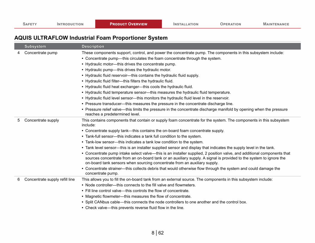
8-Inch Tellurus HMIThe Tellurus display, or HMI, displays current operations and provides operator control over the system.
2
1
3
4
986 75
15 | 62
Safety Introduction Product Overview Installation Operation Maintenance
8-Inch Tellurus HMIFeatureFeature DescriptionDescription
1 Reset button This indicates system status and allows the operator to reset the HMI. 2 Tellurus display—HMI This displays operations and system controls.3 Mounting knob This secures the HMI to the apparatus.4 Mounting bracket This secures the HMI to the apparatus.5 RJ45 connector This connects to a secondary HMI or truck Ethernet network.6 WiFi connector This connects to a WiFi antenna for wireless access.7 GPIO connector This connects external power and the control box.8 GPS connector This connects to the GPS antenna for location information.9 USB connector This connects a USB keyboard or flash drive for system configuration and updates.

16 | 62
Safety Introduction Product Overview Installation Operation Maintenance
WiFi and GPS AntennaThe antenna receives WiFi and GPS signals.
1
2
3
4

17 | 62
Safety Introduction Product Overview Installation Operation Maintenance
WiFi and GPS AntennaFeatureFeature DescriptionDescription
1 Antenna This receives the WiFi and GPS signals.2 Nut cover This secures the antenna to the apparatus.3 GPS connector This connects the GPS connector to the Tellurus HMI.4 WiFi Connector This connects the WiFi connector to the Tellurus HMI.

18 | 62
Safety Introduction Product Overview Installation Operation Maintenance
HMI CableThis cable connects the HMI to the control box and to system power. The power connector, associated connector components, and wiring are installer provided. Use the table to determine pin location.
21
6
98
117 10
3 4 5
FeatureFeature DescriptionDescription1 Deutsch connector This connects to the Tellurus display—Deutsch DT06-12SB.2 Deutsch connector This connects to apparatus power—DT04-6P-E003.3 Deutsch connector This connects to the Y-splitter receptacle.4 Y-splitter receptacle This connects to the display extension cable.5 Terminating resistor This is installed into the receptacle.6 Pin 6 CAN 2 high, yellow—optional CANbus7 Pin 5 Term 15, white +12V—back light power8 Pin 4 +12V, red—power9 Pin 3 CAN 2 low, green—optional CANbus10 Pin 2 Ground 2, black11 Pin 1 Ground, black
Note: Pin 3 and pin 6 are only connected when the second CANbus option is used.

19 | 62
Safety Introduction Product Overview Installation Operation Maintenance
HMI M12 Cable
11.81 in300 mm
1 2 3
FeatureFeature DescriptionDescription1 M12 connector This connects to the Tellurus HMI CANbus connector on the control box, or an extension cable connected to the control box.2 Cable This is a violet cable jacket.3 Deutsch connector This connects to the receptacle on the Tellurus HMI cable assembly.
20 | 62
Safety Introduction Product Overview Installation Operation Maintenance
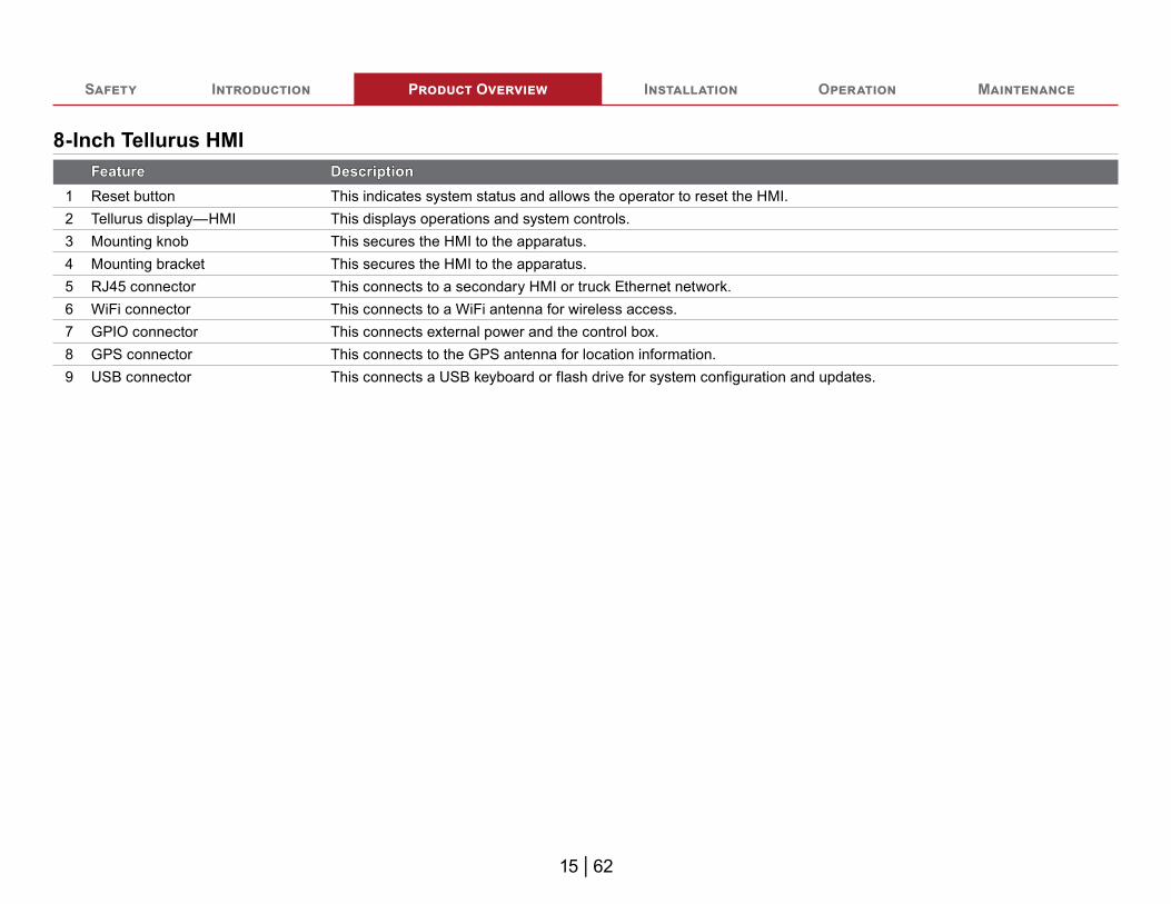
2.0 Meter CANbus Extension CableThe CANbus extension cable communicates data between the CANbus connections. It is typically a violet color. The CANbus extension cable is not interchangeable with the sensor extension cable. Note: You can connect 2 or more cables together to achieve a desired length.
6.56 ft2 m
1 32
FeatureFeature DescriptionDescription1 M12 connector This is a male connector.2 Cable This is typically a violet cable jacket.3 M12 connector This is a female connector.

21 | 62
Safety Introduction Product Overview Installation Operation Maintenance
0.5 Meter CANbus Extension CableThe CANbus extension cable communicates data between the CANbus connections. It is typically a violet color. The CANbus extension cable is not interchangeable with the sensor extension cable. Note: You can connect 2 or more cables together to achieve a desired length.
19.68 in500 mm
1 32
FeatureFeature DescriptionDescription1 M12 connector This is a male connector.2 Cable This is typically a violet cable jacket.3 M12 connector This is a female connector.

22 | 62
Safety Introduction Product Overview Installation Operation Maintenance
Installation OverviewThis equipment is intended to be installed by a person or persons with the basic knowledge of installing similar equipment. Contact Waterous with questions about installing the equipment. The installation may require the following tasks and abilities:• Locating, drilling, and cutting
features into the apparatus.• Welding• Installing the hoses and fittings.
• Routing and securing the hoses.• Routing and securing the wiring.• Calibrating the output.• Calibration and final testing.
Preparing for the InstallationUse the following guidelines before, during, and after the installation.• Read and understand all the installation instructions before installing the
equipment.• Prepare a suitable, well-lit area, and gather all the necessary tools before you
begin the installation.• Make sure that you remove any shipping plugs or caps before installing the
component. Make sure that you bring all fluids to operating levels before using the equipment.
NOTICEBefore Operation
• Read and understand all the instructions provided.• Check all fluid levels and replenish if necessary.• Remove all shipping plugs and install the operation plugs or caps.
Modifying the EquipmentThis equipment is intended to operate as designed. Do not remove, modify, or change the components in the system. Doing so will void the warranty. Contact Waterous for more information.
NOTICEModifying the equipmentcan damage componentsand void your warranty.
•
Do not modify the systemor any of its components.
•
Modification
Do not modify the system or any components. Doing so will void your warranty.
Additional DocumentationAdditional documentation is available through the MyWaterous login at Waterousco.com. Use your serial number to gain access to the service parts list associated with your system. Dimensional drawings are available through the Waterous Service department.
Optional EquipmentBe aware that the installation instruction may include optional equipment not included in your application.

23 | 62
Safety Introduction Product Overview Installation Operation Maintenance
Determining Panel and Plate LocationsUse the following guidelines to determine a location to mount the control panel and instruction plate:• Consider the cable and hose routing.• Consider accessibility during operation and maintenance.• Install instruction plates near their applicable operator panels.• Refer to the dimensional drawings for cutout and mounting hole locations for
your application.
Determining Cable and Wire RoutingUse the Wiring Best Practices document, available at www.waterousco.com, as a guide to select and route wiring for your application.

24 | 62
Safety Introduction Product Overview Installation Operation Maintenance
HMI Cables and Connections
8
4
6
5
1
2
3
7

25 | 62
Safety Introduction Product Overview Installation Operation Maintenance
HMI Cables and ConnectionsFeatureFeature DescriptionDescription
1 Tellurus HMI display This displays system operation and provides operator control of the system.2 Antenna This transmits and/or receives WiFi and GPS signals.3 HMI cable This connect the HMI to power and to the HMI M12 cable.4 HMI M12 cable This connect the HMI cable to the control box.5 Control box This connects to various components in the system and contains the programmable logic controllers (PLC).6 Terminating resistor This terminates the CANbus signal.7 HMI power cable This is the installer-supplied power cable. Refer to "HMI Cable" on page 18 for pin-out configuration. 8 System power This is the system power.

26 | 62
Safety Introduction Product Overview Installation Operation Maintenance
Connecting the Tellurus Display
2
3
4
1
Use the illustration and instructions to connect the Tellurus display.
1 Connect the compatible connector on the HMI cable assembly to the Tellurus display connector.
2 Connect the compatible connector on the HMI cable assembly to the display extension cable connector.
3 Connect compatible connector on the display extension cable to the control box—the HMI CANbus connection.Note: Use a CANbus extension cable if
necessary.4 Locally source a Deutsch DT06-3S connector
and an appropriate cable to connect system power to the receptacle on the HMI cable assembly. Power the node controller through a 10 A circuit breaker. Refer to "HMI Cable" on page 18.
27 | 62
Safety Introduction Product Overview Installation Operation Maintenance
Configuring the System
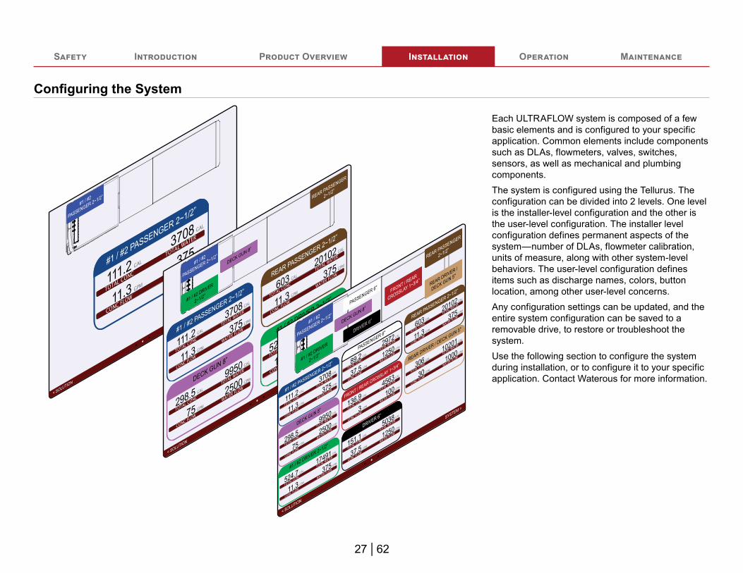
Each ULTRAFLOW system is composed of a few basic elements and is configured to your specific application. Common elements include components such as DLAs, flowmeters, valves, switches, sensors, as well as mechanical and plumbing components.The system is configured using the Tellurus. The configuration can be divided into 2 levels. One level is the installer-level configuration and the other is the user-level configuration. The installer level configuration defines permanent aspects of the system—number of DLAs, flowmeter calibration, units of measure, along with other system-level behaviors. The user-level configuration defines items such as discharge names, colors, button location, among other user-level concerns.Any configuration settings can be updated, and the entire system configuration can be saved to a removable drive, to restore or troubleshoot the system.Use the following section to configure the system during installation, or to configure it to your specific application. Contact Waterous for more information.

28 | 62
Safety Introduction Product Overview Installation Operation Maintenance
Connecting to the Tellurus HMI—External Keyboard and USB Drive
1
2
3
Use the illustration and instructions to connect to the Tellurus HMI with a keyboard and USB drive. Use the USB drive to download and save the current configuration file or to upload a new or restore to a previous configuration.To transfer configuration files, you will need the following:• A USB hub to connect the HMI to the keyboard
and USB drive.• A USB keyboard to navigate through the menu.• A USB drive to store and retrieve configuration
files.Note: Only use components with a USB standard of
2.0 or higher.1 Plug in the USB hub to the USB connection on
the HMI.2 Plug-in the USB drive to the USB hub if you are
transferring files.3 Plug-in the USB keyboard and mouse to the
USB hub.

29 | 62
Safety Introduction Product Overview Installation Operation Maintenance
Desktop IconsThe desktop icons provide direct access to common configuration settings.
Ope
ratio
nsO
pera
tions
AQUIS ULTRAFLOW
Power Cycles Report All Run Time Total Con Used Total Water
Cust
omer
Ser
vice
Cust
omer
Ser
vice
Remote Connection
System Info System Help Control System Instructions
HMI System Instructions
Hydraulic System Instructions
DLA System Instructions
Screen Capture
Con
figur
atio
nsC
onfig
urat
ions
Calibrate Touch DLA Colors DLA Names Set Background Settings Set Units
Mai
nten
ance
Mai
nten
ance
Commission DLA Diagnostics FlowmeterCalibration
Log Files Security Scan System Updates Terminal Status Alarm
30 | 62
Safety Introduction Product Overview Installation Operation Maintenance
Desktop Icons—Operation Menu
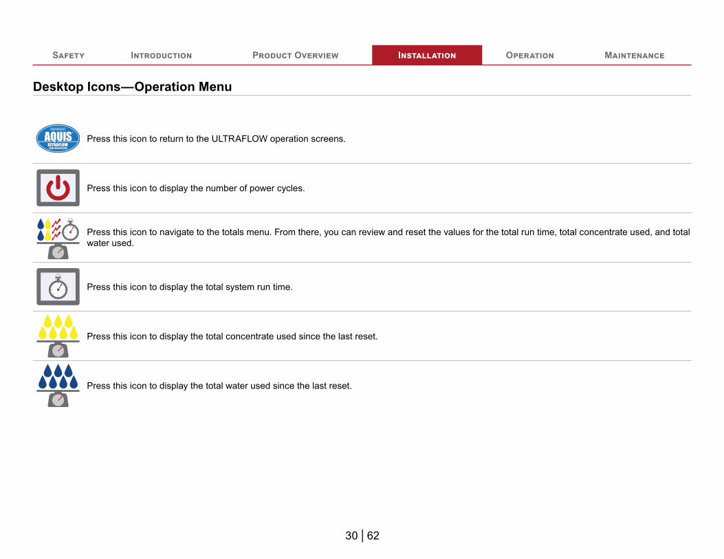
Press this icon to return to the ULTRAFLOW operation screens.
Press this icon to display the number of power cycles.
Press this icon to navigate to the totals menu. From there, you can review and reset the values for the total run time, total concentrate used, and total water used.
Press this icon to display the total system run time.
Press this icon to display the total concentrate used since the last reset.
Press this icon to display the total water used since the last reset.

31 | 62
Safety Introduction Product Overview Installation Operation Maintenance
Desktop Icons—Customer Service Menu
Press the icon to open a live troubleshooting session. Refer to: "Using the Live Troubleshooting App" on page 34.
Press the icon to display system information.
Press this icon to display a QR code that navigates to the system-help documentation.
Press the icon to navigate to the Controls instructions.
Press the icon to navigate to the HMI instructions.
Press the icon to navigate to the Hydraulics instructions.
Press the icon to navigate to the DLA instructions.
Press the icon to capture the current screen.

32 | 62
Safety Introduction Product Overview Installation Operation Maintenance
Desktop Icons—Configuration Menu
Pressing this icon initiates the touch screen calibration procedure. Refer to: "Calibrating the Touch Screen" on page 37.
Press this icon to change discharge colors.
Press this icon to change discharge names.
Press this icon and follow the instructions to install, or change, the apparatus graphic.
Press this icon to navigate to the setting menu.
Press this icon and follow the instructions to select the units used to measure the amount of water discharged.

33 | 62
Safety Introduction Product Overview Installation Operation Maintenance
Desktop Icons—Maintenance Menu
Press this icon to commission a DLA.
Press this icon to display the diagnostic report. Use the diagnostic report to verify various aspects of the operation and to troubleshoot various system components.
Press this icon to navigate to the flowmeter calibration. Use the available options to calibrate the desired flowmeter.
Press this icon to prepare a summary system log report.
Press this icon to initiate a security scan.
Press to apply previously downloaded software updates.
Press this icon to navigate to the command interface to apply terminal commands.
Press this icon to display alarm conditions that do not require immediate attention by the operator.
34 | 62
Safety Introduction Product Overview Installation Operation Maintenance
Using the Live Troubleshooting AppDownload for Apple
Download for Android
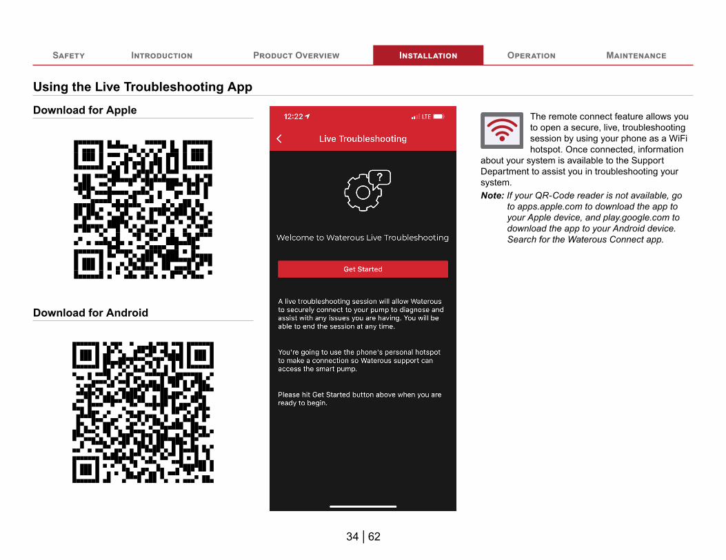
The remote connect feature allows you to open a secure, live, troubleshooting session by using your phone as a WiFi hotspot. Once connected, information
about your system is available to the Support Department to assist you in troubleshooting your system.Note: If your QR-Code reader is not available, go
to apps.apple.com to download the app to your Apple device, and play.google.com to download the app to your Android device. Search for the Waterous Connect app.
35 | 62
Safety Introduction Product Overview Installation Operation Maintenance
Using the Live Troubleshooting App
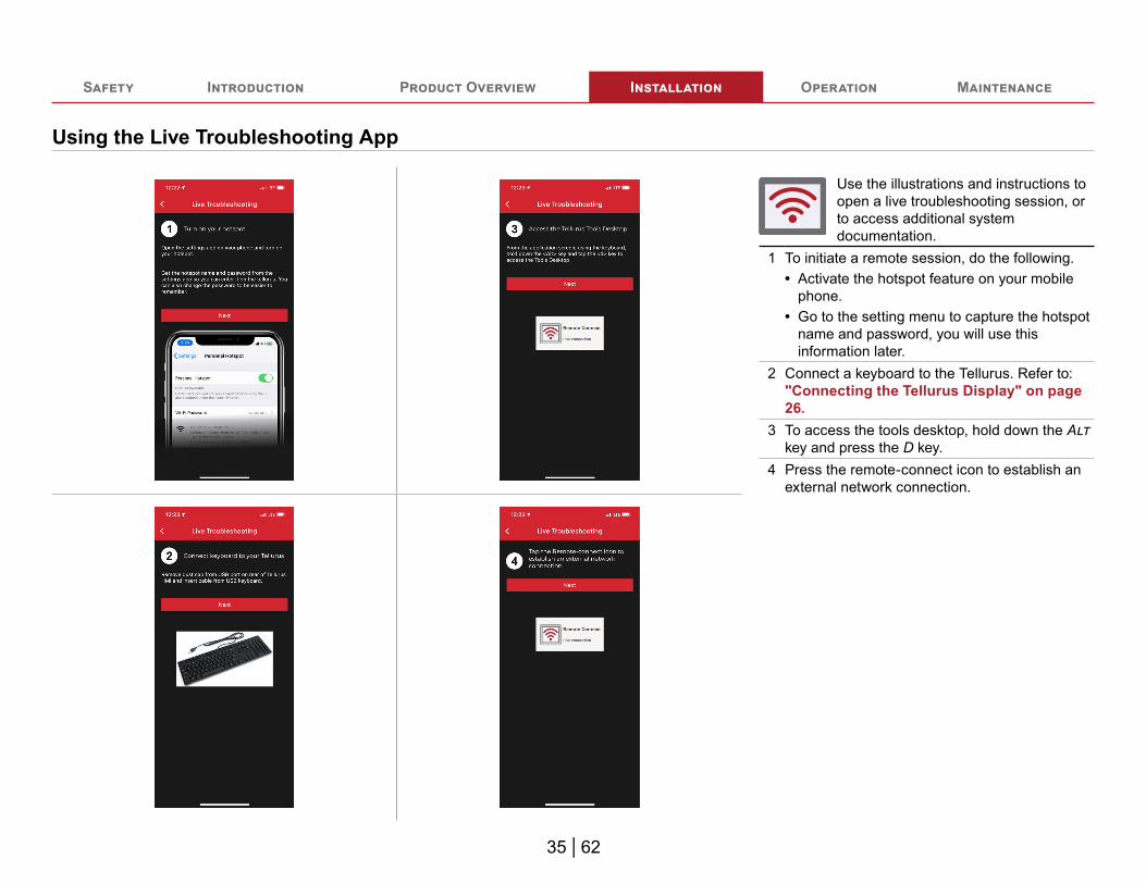
Use the illustrations and instructions to open a live troubleshooting session, or to access additional system documentation.
1 To initiate a remote session, do the following.• Activate the hotspot feature on your mobile
phone.• Go to the setting menu to capture the hotspot
name and password, you will use this information later.
2 Connect a keyboard to the Tellurus. Refer to: "Connecting the Tellurus Display" on page 26.
3 To access the tools desktop, hold down the Alt key and press the D key.
4 Press the remote-connect icon to establish an external network connection.

36 | 62
Safety Introduction Product Overview Installation Operation Maintenance
Using the Live Troubleshooting App
Remote Connection IconUse the illustrations and instructions to open a live troubleshooting session, or to access additional system documentation.
5 Locate your hotspot in the list of available hotspots.
6 Enter the hotspot passphrase into the connection manager, then press the OK button.
7 Once connected, a blue connection icon appears to indicate that the Tellurus is connected to the mobile hotspot.
37 | 62
Safety Introduction Product Overview Installation Operation Maintenance
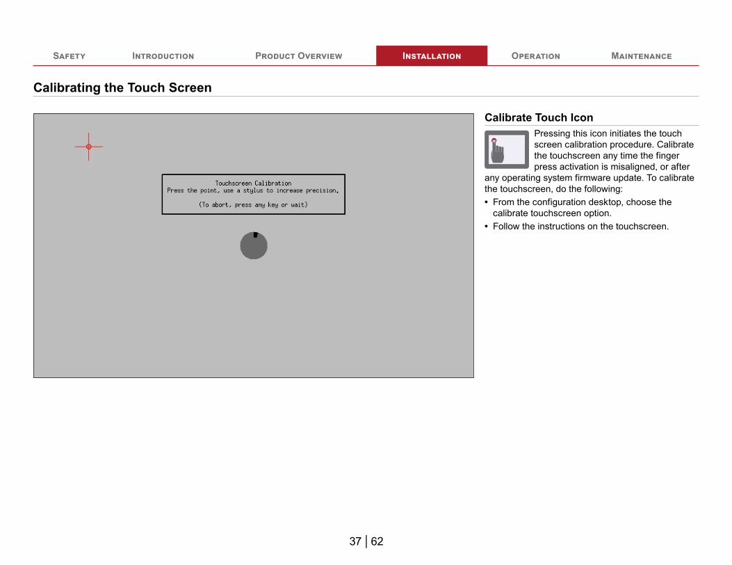
Calibrating the Touch Screen
Calibrate Touch IconPressing this icon initiates the touch screen calibration procedure. Calibrate the touchscreen any time the finger press activation is misaligned, or after
any operating system firmware update. To calibrate the touchscreen, do the following:• From the configuration desktop, choose the
calibrate touchscreen option.• Follow the instructions on the touchscreen.

38 | 62
Safety Introduction Product Overview Installation Operation Maintenance
Command Interface MenuMost commonly used configuration commands are available through the shortcuts on the desktop. Additional commands are available through the command interface. Use the command interface to access the additional command functions when necessary. Review the menu description to navigate to the desired function. Continue following the menu descriptions as you navigate to the desired setting or adjustment.
-------------------------------------------------------------------------------**** Tellurus Command InterfaceTellurus Command Interface ****-------------------------------------------------------------------------------Enter any of the following commands at the prompt to perform HMI functions:
[helphelp] - Show command interface help[exitexit] - Exit command interface and restart application[operateoperate] - Operating status menu[reportreport] - Reporting functions menu[serviceservice] - Customer service menu[configconfig] - Tellurus configuration menu[maintmaint] - System maintenance and diagnostics menu[calcal] - System calibration menu[netnet] - Network settings menu[termterm] - Open terminal command shell[patchpatch] - Apply incremental system patch files[restartrestart] - Shutdown and restart
-------------------------------------------------------------------------------command:

39 | 62
Safety Introduction Product Overview Installation Operation Maintenance
Powering Up the Display
1 2
3
< SOLUTION SYSTEM >
REAR DRIVER / DECK GUN 5"
306 1020130 1000
REAR PASSENGER 2~1/2”
603 2010211.3 375
REAR PASSENGER2~1/2”
REAR DRIVER /DECK GUN 5"
DRIVER 6”
151.1 503837.5 1250
DRIVER 6”
FRONT / REAR CROSSLAY 1~3/4”
136.9 45633 100
FRONT / REARCROSSLAY 1~3/4”
PASSENGER 6"
89.2 297237.5 1250
PASSENGER 6"
#1 / #2 DRIVER 2~1/2”
524.7 1749111.3 375
#1 / #2 DRIVER2~1/2”
DECK GUN 8”
298.5 995075 2500
DECK GUN 8”
#1 / #2 PASSENGER 2~1/2”
111.2 370811.3 375
#1 / #2PASSENGER 2~1/2”
4
Use the illustrations and instructions to monitor the start-up as the system comes online. The display powers-up automatically with the pump panel.
1 This is the first start-up screen. This screen indicates that the display is receiving power and the boot sequence has initiated.
2 This screen displays as the Tellurus begins to communicate with the PLC.Note: The operating system and the software
versions are displayed in the lower corners.
3 A pulsating ring animates as the Tellurus and PLC communicate.
4 Once the start-up sequence is complete the system displays the gauge screen.
Note: All the screens described in this section are configurable to your specific application. The appearance of your screen may differ than what is illustrated. The illustrations in this section are based on the 15-inch HMI. The 8-inch HMI displays the lower 2/3 of the 15-inch HMI—omitting the apparatus graphic and discharge locations. Apply the concepts described in the instruction to your application. Contact Waterous for more information.
40 | 62
Safety Introduction Product Overview Installation Operation Maintenance
HMI Display—Screen Size
< SOLUTION SYSTEM >
REAR DRIVER / DECK GUN 5"
306 1020130 1000
REAR PASSENGER 2~1/2”
603 2010211.3 375
REAR PASSENGER2~1/2”
REAR DRIVER /DECK GUN 5"
DRIVER 6”
151.1 503837.5 1250
DRIVER 6”
FRONT / REAR CROSSLAY 1~3/4”
136.9 45633 100
FRONT / REARCROSSLAY 1~3/4”
PASSENGER 6"
89.2 297237.5 1250
PASSENGER 6"
#1 / #2 DRIVER 2~1/2”
524.7 1749111.3 375
#1 / #2 DRIVER2~1/2”
DECK GUN 8”
298.5 995075 2500
DECK GUN 8”
#1 / #2 PASSENGER 2~1/2”
111.2 370811.3 375
#1 / #2PASSENGER 2~1/2”
1
< SOLUTION SYSTEM >
REAR DRIVER / DECK GUN 5"
306 1020130 1000
REAR PASSENGER 2~1/2”
603 2010211.3 375
DRIVER 6”
151.1 503837.5 1250
FRONT / REAR CROSSLAY 1~3/4”
136.9 45633 100
PASSENGER 6"
89.2 297237.5 1250
#1 / #2 DRIVER 2~1/2”
524.7 1749111.3 375
DECK GUN 8”
298.5 995075 2500
#1 / #2 PASSENGER 2~1/2”
111.2 370811.3 375
2
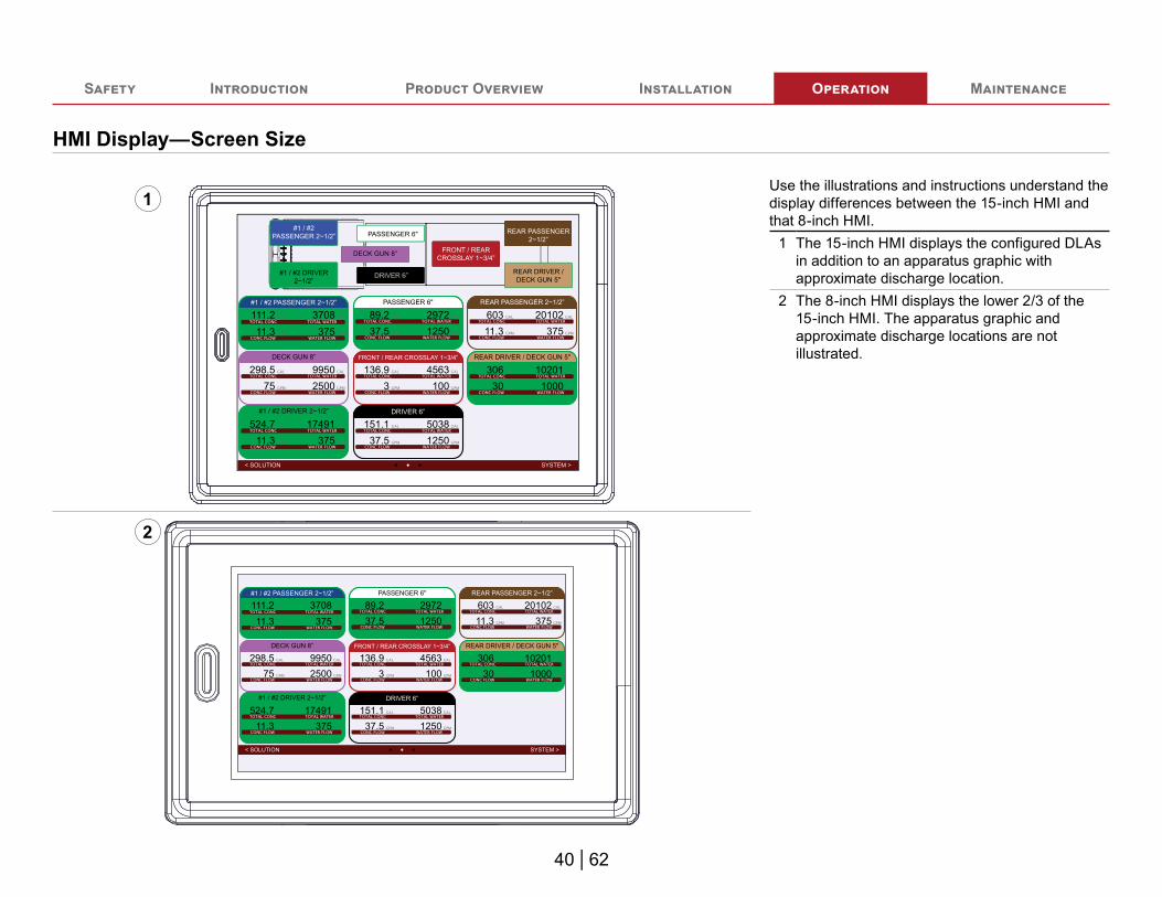
Use the illustrations and instructions understand the display differences between the 15-inch HMI and that 8-inch HMI.
1 The 15-inch HMI displays the configured DLAs in addition to an apparatus graphic with approximate discharge location.
2 The 8-inch HMI displays the lower 2/3 of the 15-inch HMI. The apparatus graphic and approximate discharge locations are not illustrated.

41 | 62
Safety Introduction Product Overview Installation Operation Maintenance
HMI Display—Orb Button
< SOLUTION SYSTEM >
REAR DRIVER / DECK GUN 5"
306 1020130 1000
REAR PASSENGER 2~1/2”
603 2010211.3 375
REAR PASSENGER2~1/2”
REAR DRIVER /DECK GUN 5"
DRIVER 6”
151.1 503837.5 1250
DRIVER 6”
FRONT / REAR CROSSLAY 1~3/4”
136.9 45633 100
FRONT / REARCROSSLAY 1~3/4”
PASSENGER 6"
89.2 297237.5 1250
PASSENGER 6"
#1 / #2 DRIVER 2~1/2”
524.7 1749111.3 375
#1 / #2 DRIVER2~1/2”
DECK GUN 8”
298.5 995075 2500
DECK GUN 8”
#1 / #2 PASSENGER 2~1/2”
111.2 370811.3 375
#1 / #2PASSENGER 2~1/2”
1
20%
50%
80%
20%
50%
80%
98
GPM
170.0
200064781
1943.4112.0
< GAUGE SOLUTION >
45
4,000
PRESSURERELIEF
DECK GUN 8”
REAR DRIVER /DECK GUN 5"
PASSENGER 6"
DRIVER 6”
FRONT / REARCROSSLAY 1~3/4”
REAR PASSENGER2.5"
#1 / #2 DRIVER2~1/2”
#1 / #2PASSENGER 2~1/2”
< SOLUTION SYSTEM >
REAR DRIVER / DECK GUN 5"
306 1020130 1000
REAR PASSENGER 2~1/2”
603 2010211.3 375
REAR PASSENGER2~1/2”
REAR DRIVER /DECK GUN 5"
DRIVER 6”
151.1 503837.5 1250
DRIVER 6”
FRONT / REAR CROSSLAY 1~3/4”
136.9 45633 100
FRONT / REARCROSSLAY 1~3/4”
PASSENGER 6"
89.2 297237.5 1250
PASSENGER 6"
#1 / #2 DRIVER 2~1/2”
524.7 1749111.3 375
#1 / #2 DRIVER2~1/2”
DECK GUN 8”
298.5 995075 2500
DECK GUN 8”
#1 / #2 PASSENGER 2~1/2”
111.2 370811.3 375
#1 / #2PASSENGER 2~1/2”
< SYSTEM GAUGE >
REAR PASSENGER2~1/2”
DRIVER 6”
FRONT / REARCROSSLAY 1~3/4”
PASSENGER 6"
#1 / #2 DRIVER2~1/2”
DECK GUN 8”
#1 / #2 PASSENGER 2.5”
GAL GAL
CONCENTRATE
PRESSURERELIEF 750
111.2
3.0
3708
GPM
37511.3
112.0
#1 / #2PASSENGER 2~1/2”
CONCENTRATE ON
2
3
Use the illustrations and instructions understand the ORB button and its function.
1 The Orb button illuminates white when the HMI is powered up. Additional, the ORB button provides quick navigation to commonly accessed screens.
2 From any screen, tap the ORB button to navigate to the gauge screen.Note: Make sure that you release the Orb
button once it turns blue.3 From any screen, tap the ORB button twice
within 2 seconds to navigate to the desktop application screen. Press the ORB button once to return to the gauge screen.Note: Release the Orb button once it turns
blue.
42 | 62
Safety Introduction Product Overview Installation Operation Maintenance
DLA Gauge Screen
< SOLUTION SYSTEM >
REAR DRIVER / DECK GUN 5"
306 1020130 1000
REAR PASSENGER 2~1/2”
603 2010211.3 375
REAR PASSENGER2~1/2”
REAR DRIVER /DECK GUN 5"
DRIVER 6”
151.1 503837.5 1250
DRIVER 6”
FRONT / REAR CROSSLAY 1~3/4”
136.9 45633 100
FRONT / REARCROSSLAY 1~3/4”
PASSENGER 6"
89.2 297237.5 1250
PASSENGER 6"
#1 / #2 DRIVER 2~1/2”
524.7 1749111.3 375
#1 / #2 DRIVER2~1/2”
DECK GUN 8”
298.5 995075 2500
DECK GUN 8”
#1 / #2 PASSENGER 2~1/2”
111.2 370811.3 375
#1 / #2PASSENGER 2~1/2”
3 54
1
2
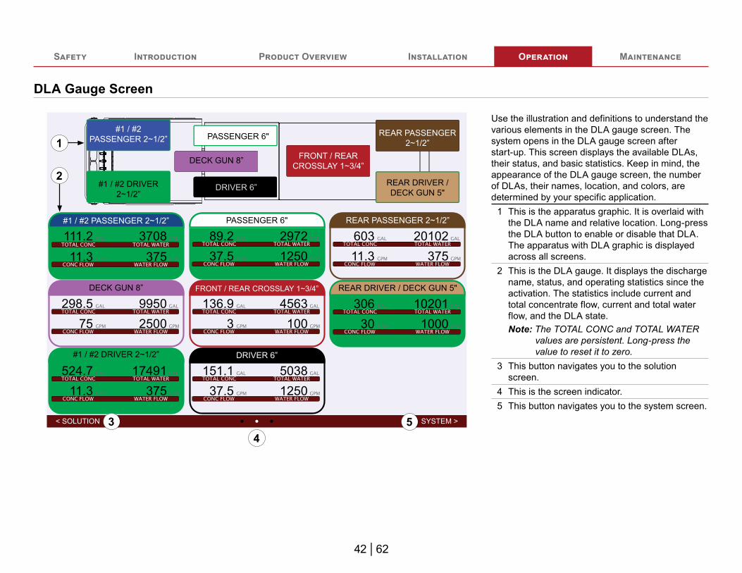
Use the illustration and definitions to understand the various elements in the DLA gauge screen. The system opens in the DLA gauge screen after start-up. This screen displays the available DLAs, their status, and basic statistics. Keep in mind, the appearance of the DLA gauge screen, the number of DLAs, their names, location, and colors, are determined by your specific application.
1 This is the apparatus graphic. It is overlaid with the DLA name and relative location. Long-press the DLA button to enable or disable that DLA. The apparatus with DLA graphic is displayed across all screens.
2 This is the DLA gauge. It displays the discharge name, status, and operating statistics since the activation. The statistics include current and total concentrate flow, current and total water flow, and the DLA state.Note: The TOTAL CONC and TOTAL WATER
values are persistent. Long-press the value to reset it to zero.
3 This button navigates you to the solution screen.
4 This is the screen indicator.5 This button navigates you to the system screen.

43 | 62
Safety Introduction Product Overview Installation Operation Maintenance
Solution Screen—Buttons
< SYSTEM GAUGE >
REAR PASSENGER2~1/2”
DRIVER 6”
FRONT / REARCROSSLAY 1~3/4”
PASSENGER 6"
#1 / #2 DRIVER2~1/2”
DECK GUN 8”
#1 / #2 PASSENGER 2.5”
GAL GAL
CONCENTRATE
PRESSURERELIEF 750
111.2
3.0
3708
GPM
37511.3
112.0
#1 / #2PASSENGER 2~1/2”
CONCENTRATE ON
2
14 43
5 7
8
6
3 3
Use the illustration and definitions to understand the information displayed. Short-press a DLA button to open the DLA solution screen. From this screen you can enable and disable concentrate flow to the discharge, adjust the percent, and view the current and total flow values.
1 This button displays the DLA state, enabled or disabled. Long-press this button to change the DLA state.
2 This is the selected concentrate source, and is determined by a signal provided to the system.
3 These buttons directly adjust the concentrate set-point. You can configure each button to values appropriate for your application.
4 This adjust the concentrate percent set-point at 0.1 increments.
5 This button navigates you to the system screen.6 This is the screen indicator.7 This button navigates you to the DLA gauge
screen.8 This button enables simulation flow mode. This
simulates discharge water flow.

44 | 62
Safety Introduction Product Overview Installation Operation Maintenance
Solution Screen—Telemetry
< SYSTEM GAUGE >
REAR PASSENGER2~1/2”
DRIVER 6”
FRONT / REARCROSSLAY 1~3/4”
PASSENGER 6"
#1 / #2 DRIVER2~1/2”
DECK GUN 8”
#1 / #2 PASSENGER 2.5”
GAL GAL
CONCENTRATE
PRESSURERELIEF 750
111.2
3.0
3708
GPM
37511.3
112.0
#1 / #2PASSENGER 2~1/2”
CONCENTRATE ON
1
2 3
4
6
5
Use the illustration and definitions to understand the information displayed. Short-press a DLA button to open the DLA solution screen. From this screen you can enable and disable concentrate flow to the discharge, adjust the concentrate percent, and view the current and total flow values.
1 This is the name of the selected DLA.2 This is the total amount of concentrate
dispensed from the selected DLA since the last reset. Long-press the value to reset it to zero.
3 This is the total amount of water dispensed from the selected DLA since the last reset. Long-press the value to reset it to zero.
4 This graphically and numerically shows the current concentrate flow rate for the selected DLA, as well as the concentrate-line pressure. Refer to: "Solution Screen—Concentrate Gauge" on page 45.
5 This graphically and numerically shows total amount of water dispensed from the selected discharge since the last reset. Refer to: "Solution Screen—Water Gauge" on page 46.
6 This is the concentrate percent set-point.

45 | 62
Safety Introduction Product Overview Installation Operation Maintenance
Solution Screen—Concentrate Gauge
PRESSURERELIEF11.3
112.0
2
3
4
5
1
6
7
Use the illustration and definitions to understand the concentrate gauge features.
1 This needle indicates the concentrate line pressure.
2 This indexes the concentrate line pressure.3 This needle indicates the expected value of the
concentrate output.4 This gauge indicates the actual value of the
concentrate output.5 This index represents the amount of
concentrate flowing through a DLA with respect to its capacity. By default, the green segment is 0% to approximately 90% of DLA capacity. The yellow segment is approximately 90% to 100% of DLA capacity. The red segment is outside the capacity of the DLA.Note: You can configure where the yellow and
red segments appear in the index to best represent your application.
6 This displays the numerical value of the concentrate flowing as read by the DLA flowmeter.Note: You can configure the units displayed for
your application.7 This displays the numerical value of the
pressure in the concentrate line as measured by the concentrate line pressure transducer.Note: You can configure the units displayed for
your application.

46 | 62
Safety Introduction Product Overview Installation Operation Maintenance
Solution Screen—Water Gauge
750
GPM
375
2
3
1
Use the illustration and definitions to understand the water gauge features.
1 This needle indicates the water flow in the discharge associated with the DLA.
2 This displays the numerical value of the water flowing in the solution-capable discharge associated with the DLA.Note: You can configure the units displayed for
your application.3 This value indicates the maximum flow of the
solution-capable discharge associated with the DLA.Note: You can configure this value for each
discharge in your application.

47 | 62
Safety Introduction Product Overview Installation Operation Maintenance
System Screen—Buttons
20%
50%
80%
20%
50%
80%
98
GPM
170.0
200064781
1943.4112.0
< GAUGE SOLUTION >
45
4,000
PRESSURERELIEF
DECK GUN 8”
REAR DRIVER /DECK GUN 5"
PASSENGER 6"
DRIVER 6”
FRONT / REARCROSSLAY 1~3/4”
REAR PASSENGER2.5"
#1 / #2 DRIVER2~1/2”
#1 / #2PASSENGER 2~1/2”
4
21
3
68
86
75
9 1110
Use the illustration and definitions to understand the buttons on the system display. The system screen displays the current and total flow of water and concentrate across all DLAs. It also monitors and controls the refill, transfer, and relay processes.
1 This is the selected concentrate source, and is determined by a signal provided to the system.
2 This enables the refill process when the concentrate source is set to auxiliary.
3 Press and hold this button to manually prime the concentrate pump.
4 This enables the relay or transfer process and operates as follows:• The transfer process is available when the
concentrate source is on-board.• The relay process is available when the
concentrate source is auxiliary.5 This is the relay or transfer rate set-point slider.
Adjust this to set a general value.6 This incrementally adjusts the relay or transfer
rate set-point. Adjust this to fine-tune the value.7 This is the refill rate set-point slider. Adjust this
to set a general value.8 This incrementally adjusts the refill rate set-
point. Adjust this to fine-tune the value.9 This button navigates you to the DLA gauge
screen.10 This is the screen indicator. It shows you the
screen navigation options.11 This button navigates you to the solution
screen.

48 | 62
Safety Introduction Product Overview Installation Operation Maintenance
System Screen—Telemetry
20%
50%
80%
20%
50%
80%
98
GPM
170.0
200064781
1943.4112.0
< GAUGE SOLUTION >
45
4,000
PRESSURERELIEF
DECK GUN 8”
REAR DRIVER /DECK GUN 5"
PASSENGER 6"
DRIVER 6”
FRONT / REARCROSSLAY 1~3/4”
REAR PASSENGER2.5"
#1 / #2 DRIVER2~1/2”
#1 / #2PASSENGER 2~1/2”
2
1
3
4
56
Use the illustration and definitions to understand the gauges on the system display. The system screen monitors and displays the total amount of concentrate and water flowed by the system. Your application may not have the transfer and refill options shown in the illustration.
1 This graphically and numerically shows the current concentrate flow rate for all active DLAs, as well as the concentrate-line pressure.
2 This graphically and numerically shows the current water flow rate for all active DLAs.
3 This shows the total amount of water flowed by the system since the last reset. Long-press the number to reset the value to zero.
4 This shows the total amount of concentrate flowed by the system since the last reset. Long-press the number to reset the value to zero.
5 This graphically shows what percentage of the selected set-point the system is achieving during the refill process.
6 This graphically shows what percentage of the selected set-point the system is achieving during the relay or transfer process.

49 | 62
Safety Introduction Product Overview Installation Operation Maintenance
Enabling and Disabling a DLA—Screen Views
< SOLUTION SYSTEM >
REAR DRIVER / DECK GUN 5"
306 1020130 1000
REAR PASSENGER 2~1/2”
603 2010211.3 375
REAR PASSENGER2~1/2”
REAR DRIVER /DECK GUN 5"
DRIVER 6”
151.1 503837.5 1250
DRIVER 6”
FRONT / REAR CROSSLAY 1~3/4”
136.9 45633 100
FRONT / REARCROSSLAY 1~3/4”
PASSENGER 6"
89.2 297237.5 1250
PASSENGER 6"
#1 / #2 DRIVER 2~1/2”
524.7 1749111.3 375
#1 / #2 DRIVER2~1/2”
DECK GUN 8”
298.5 995075 2500
DECK GUN 8”
#1 / #2PASSENGER 2~1/2”
#1 / #2 PASSENGER 2~1/2”
111.2 370811.3 375
2
1
< SYSTEM GAUGE >
REAR PASSENGER2~1/2”
DRIVER 6”
FRONT / REARCROSSLAY 1~3/4”
PASSENGER 6"
#1 / #2 DRIVER2~1/2”
DECK GUN 8”
#1 / #2 PASSENGER 2.5”
GAL GAL
CONCENTRATE
PRESSURERELIEF 750
111.2
3.0
3708
GPM
37511.3
112.0
#1 / #2PASSENGER 2~1/2”
CONCENTRATE ON
4
3
Use the illustrations and instructions to enable and disable a discharge. A discharge consists of a DLA and dedicated waterline from the fire pump. Enabling a discharge on the screen enables the associated DLA that is then activated by flowing water through the dedicated waterline. After start-up, the system opens to the DLA Gauge screen.
1 The gauge screen displays the available discharges, their status, and their statistics since the last reset. Enable and disable any discharge by doing the following:• Long-press any DLA button to enable that
DLA. The button appearance changes to indicate that the DLA is enabled. A border appears around the button, and the DLA name animates when the DLA is active.
• Long-pressing an enabled DLA disables that DLA, and reverts the button to its original appearance.
• Short-press any DLA button from any screen to navigate to the solution screen for that DLA.
2 The DLA information box updates to show the status, and the associated statistics update when it is active.
3 The concentrate source icon animates on the solution screen for any DLA that is enabled.
4 Another indication that the DLA is enabled is that the Concentrate On/Off is in the On state. Press the Concentrate On/Off button to disable that DLA.

50 | 62
Safety Introduction Product Overview Installation Operation Maintenance
Enabling and Disabling a Discharge—System View
1
4
2
3
5
Use the illustration and instructions to understand the system activity when you enable a DLA. Keep in mind that an enabled DLA is only active when the associated line is flowing water.Note: For instructional purposes, this illustration
only focuses on the specific activity in the system that best conveys the topic.
1 The fire pump flows water into the discharge.2 The enabled DLA measures the water flow in
the discharge.3 The concentrate pump activates.4 The magnetic flowmeter measures the amount
concentrate flowing in the DLA, while the valve meters the concentrate proportioned into the discharge to produce the selected solution.
5 The concentrate source is selected by the concentrate-source valve. The valve switches between an on-board or auxiliary concentrate source. The valve position signal is provided to the system—which uses this information to determine when to monitor the on-board concentrate level.

51 | 62
Safety Introduction Product Overview Installation Operation Maintenance
Adjusting the Solution Screen
< SYSTEM GAUGE >
REAR PASSENGER2~1/2”
DRIVER 6”
FRONT / REARCROSSLAY 1~3/4”
PASSENGER 6"
#1 / #2 DRIVER2~1/2”
DECK GUN 8”
#1 / #2 PASSENGER 2.5”
GAL GAL
CONCENTRATE
PRESSURERELIEF 750
111.2
3.0
3708
GPM
37511.3
112.0
#1 / #2PASSENGER 2~1/2”
CONCENTRATE ON
23
1 Use the illustration and instructions to adjust the concentrate percentage for a specific discharge.
1 Typically the solution parameters are set during calibration or testing. Use the solution to screen adjust the concentrate percentage during operation.
2 Use the Concentrate-Percent buttons to increase or decrease the concentrate percent in 0.1% increments.
3 To disable the DLA, long-press the DLA button on the apparatus graphic, or long-press the Concentrate On/Off button.

52 | 62
Safety Introduction Product Overview Installation Operation Maintenance
Switching the Concentrate Source—Screen View
1 20%
50%
80%
20%
50%
80%
98
GPM
170.0
200064781
1943.4112.0
< GAUGE SOLUTION >
45
4,000
PRESSURERELIEF
DECK GUN 8”
REAR DRIVER /DECK GUN 5"
PASSENGER 6"
DRIVER 6”
FRONT / REARCROSSLAY 1~3/4”
REAR PASSENGER2.5"
#1 / #2 DRIVER2~1/2”
#1 / #2PASSENGER 2~1/2”
1
1
2 20%
50%
80%
20%
50%
80%
98
GPM
170.0
200064781
1943.4112.0
< GAUGE SOLUTION >
45
4,000
PRESSURERELIEF
DECK GUN 8”
REAR DRIVER /DECK GUN 5"
PASSENGER 6"
DRIVER 6”
FRONT / REARCROSSLAY 1~3/4”
REAR PASSENGER2.5"
#1 / #2 DRIVER2~1/2”
#1 / #2PASSENGER 2~1/2”
2
2 2
Use the illustrations and instructions to understand how the concentrate source is determined by the system. The system installer provides and defines a signal to the system as well as a method for switching between on-board and auxiliary sources. The concentrate source affects system features and functions.Note: The illustrations and instructions reflect a
typical application.1 With the on-board source selected, the system
functions as follows:• The concentrate supply icon indicates an
on-board source is selected.• The system monitors the supply through the
tank-level sensors.• The transfer function is available.
2 With the auxiliary source selected, the system functions as follows:• The concentrate supply icon indicates an
auxiliary source is selected.• The operator monitors the supply levels.• The refill and relay function is available.

53 | 62
Safety Introduction Product Overview Installation Operation Maintenance
Switching the Concentrate Source Mode—System View
1
Use the illustrations and instructions to understand the system activity when you set it to an auxiliary concentrate source.Note: For instructional purposes, this illustration
only focuses on the specific activity in the system that best conveys the topic.
1 When set to auxiliary supply mode, a valve is used to change the concentrate source from the on-board supply tank to the auxiliary system. When sourcing concentrate from an auxiliary source, the system cannot measure the supply level—the concentrate supply must be managed by the operator.Note: Do not operate the equipment without
providing concentrate or water to pump through the system.

54 | 62
Safety Introduction Product Overview Installation Operation Maintenance
Refilling the On-Board Supply Tank—Screen View
1 20%
50%
80%
20%
50%
80%
98
GPM
170.0
200064781
1943.4112.0
< GAUGE SOLUTION >
45
4,000
PRESSURERELIEF
DECK GUN 8”
REAR DRIVER /DECK GUN 5"
PASSENGER 6"
DRIVER 6”
FRONT / REARCROSSLAY 1~3/4”
REAR PASSENGER2.5"
#1 / #2 DRIVER2~1/2”
#1 / #2PASSENGER 2~1/2”
2 3
20%
50%
80%
20%
50%
80%
98
GPM
170.0
200064781
1943.4112.0
< GAUGE SOLUTION >
45
4,000
PRESSURERELIEF
DECK GUN 8”
REAR DRIVER /DECK GUN 5"
PASSENGER 6"
DRIVER 6”
FRONT / REARCROSSLAY 1~3/4”
REAR PASSENGER2.5"
#1 / #2 DRIVER2~1/2”
#1 / #2PASSENGER 2~1/2”
5
4
Use the illustrations and instructions to refill the on-board concentrate-supply tank from an external source. This is useful when manually refilling the on-board supply tank is not practical. Refilling the on-board supply tank can take place concurrently with normal discharge operations.
1 Set the concentrate-supply source to auxiliary.2 Verify that the concentrate-supply icon is
showing that auxiliary supply is selected.3 Press the Refill button to start the process.
The system stops when the concentrate-supply tank is full.
4 The Refill button changes appearance and concentrate-supply icon begins to animate when the refill process is active.
5 Adjust the slider to the desired refill rate.
55 | 62
Safety Introduction Product Overview Installation Operation Maintenance
Refilling the On-Board Supply Tank—System View
1
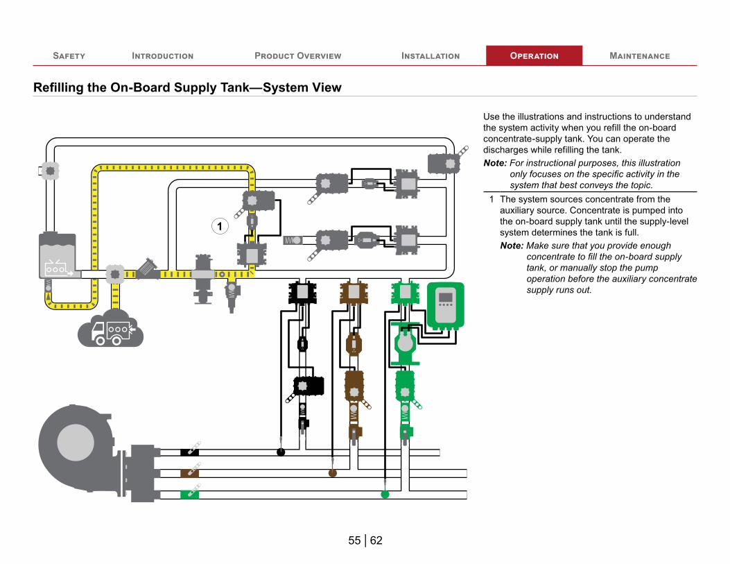
Use the illustrations and instructions to understand the system activity when you refill the on-board concentrate-supply tank. You can operate the discharges while refilling the tank.Note: For instructional purposes, this illustration
only focuses on the specific activity in the system that best conveys the topic.
1 The system sources concentrate from the auxiliary source. Concentrate is pumped into the on-board supply tank until the supply-level system determines the tank is full.Note: Make sure that you provide enough
concentrate to fill the on-board supply tank, or manually stop the pump operation before the auxiliary concentrate supply runs out.

56 | 62
Safety Introduction Product Overview Installation Operation Maintenance
Relaying Concentrate
20%
50%
80%
20%
50%
80%
98
GPM
170.0
200064781
1943.4112.0
< GAUGE SOLUTION >
45
4,000
PRESSURERELIEF
DECK GUN 8”
REAR DRIVER /DECK GUN 5"
PASSENGER 6"
DRIVER 6”
FRONT / REARCROSSLAY 1~3/4”
REAR PASSENGER2.5"
#1 / #2 DRIVER2~1/2”
#1 / #2PASSENGER 2~1/2”
1
2
3
Use the illustrations and instructions to transfer concentrate to another location. If included in your application, you can use the transfer line to move the concentrate from the on-board tank, or external source, to another location. You can operate the discharges while transferring concentrate.Note: For instructional purposes, the system
illustration only focuses on the specific activity in the system that best conveys the topic.
1 Press the Relay button to begin the relay process.
2 Adjust the slide to the desired relay rate.3 The system relays the concentrate from an
auxiliary source to the transfer line.

57 | 62
Safety Introduction Product Overview Installation Operation Maintenance
Manually Priming the Concentrate Line
20%
50%
80%
20%
50%
80%
98
GPM
170.0
200064781
1943.4112.0
< GAUGE SOLUTION >
45
4,000
PRESSURERELIEF
DECK GUN 8”
REAR DRIVER /DECK GUN 5"
PASSENGER 6"
DRIVER 6”
FRONT / REARCROSSLAY 1~3/4”
REAR PASSENGER2.5"
#1 / #2 DRIVER2~1/2”
#1 / #2PASSENGER 2~1/2”
1
2
Use the illustrations and instructions to manually prime the concentrate line. The system automatically primes before operation. You can also manually prime the system by pressing the prime button until the system is primed.Note: For instructional purposes, the system
illustration only focuses on the specific activity in the system that best conveys the topic.
1 Press and hold the Prime button until the system is primed.
2 The system evacuates the air in the lines to atmosphere as the concentrate fills the lines. During prime operation a small amount of concentrate will return to the on-board tank. Make sure that the tank capacity is sufficient to allow for normal priming operation. You can also prime the system from an auxiliary concentrate source. However, extended priming from an auxiliary supply is not recommended as this may overflow the on-board tank.

58 | 62
Safety Introduction Product Overview Installation Operation Maintenance
Transferring Concentrate
20%
50%
80%
20%
50%
80%
98
GPM
170.0
200064781
1943.4112.0
< GAUGE SOLUTION >
45
4,000
PRESSURERELIEF
DECK GUN 8”
REAR DRIVER /DECK GUN 5"
PASSENGER 6"
DRIVER 6”
FRONT / REARCROSSLAY 1~3/4”
REAR PASSENGER2.5"
#1 / #2 DRIVER2~1/2”
#1 / #2PASSENGER 2~1/2”
1
3
2
Use the illustrations and instructions to transfer concentrate to another location. If included in your application, you can use the transfer line to move the concentrate from the on-board tank to another location. You can operate the discharges while transferring concentrate.Note: For instructional purposes, the system
illustration only focuses on the specific activity in the system that best conveys the topic.
1 Press the Transfer button to begin the transfer process.
2 The system transfers the concentrate from the selected source to the transfer line.
3 Adjust the slider to the desired rate.

59 | 62
Safety Introduction Product Overview Installation Operation Maintenance
Verifying Concentrate Output with Water
2
1
3
< SYSTEM GAUGE >
SIM FLOW
REAR PASSENGER2~1/2”
DRIVER 6”
FRONT / REARCROSSLAY 1~3/4”
PASSENGER 6"
#1 / #2 DRIVER2~1/2”
DECK GUN 8”
#1 / #2 PASSENGER 2.5”
GAL GAL
CONCENTRATE
PRESSURERELIEF 750
0.0
3.0
0.0
GPM
00
42.0
#1 / #2PASSENGER 2~1/2”
CONCENTRATE OFF
4
56
Preparing for ValidationUse the illustrations and instructions to verify that the DLA injects the expected amount of concentrate into the solution-capable discharge. This can be done without flowing water in the waterway discharge by placing the system into simulated flow mode.
1 Connect a clean water source to the auxiliary intake.
2 Make sure that you set the prime bypass valve to divert the water away from the concentrate supply tank to avoid contaminating concentrate.
NOTICE
• Priming with water cancontaminate the on-boardconcentrate supply.
Concentrate SupplyContamination
• Divert water to preventconcentrate contamination.
3 Prepare the DLA by doing the following:• Position a container suitable to collect and
measure the concentrate, or used a calibrated, external flowmeter.
• Set the cal/inject valve to divert concentrate for collection and measurement.
4 Long-press the Sim Flow button to enable simulated flow mode.
5 Adjust the simulated flow value by sliding your finger along the WATER FLOW bar.
6 Set the desired concentrate percent.

60 | 62
Safety Introduction Product Overview Installation Operation Maintenance
Verifying Concentrate Output with Water
PRESSURERELIEF0.0
182.0
7
PRESSURERELIEF30.0
182.0 8
< SYSTEM GAUGE >
SIM FLOW
REAR PASSENGER2~1/2”
DRIVER 6”
FRONT / REARCROSSLAY 1~3/4”
PASSENGER 6"
#1 / #2 DRIVER2~1/2”
DECK GUN 8”
#1 / #2 PASSENGER 2.5”CONCENTRATE
1000
GPM
1000PRESSURERELIEF
3.0
30182.0
GAL GAL60 2000
#1 / #2PASSENGER 2~1/2”
CONCENTRATE ON
9
10
11
Operating Simulated Flow ModeUse the illustrations and instructions to operate the system in simulated flow mode.
7 This needle indicates the expected value for the concentrate output.
8 Begin flowing concentrate by long-pressing the Concentrate On/Off button. The flow rate displayed when flowing concentrate should match the expected value represented by the needle.Use the volumetric method or a calibrated, external flowmeter collect concentrate sample during steady-state operation.
9 Long-press the Concentrate On/Off button to stop flowing concentrate.
10 Long-press the Sim Flow button to disable simulated flow mode.
11 After completing the simulation, compare the values expected by the system with the collected output.Drain any water remaining in the concentrate line to prevent future concentrate contamination.

Safety Introduction Product Overview Installation Operation Maintenance
61 | 62
Maintenance ScheduleNo scheduled maintenance is required for the control system. However, it is recommended that you periodically inspect the system to reveal excessive debris buildup, worn components, or any developing leaks. Consider environmental conditions, hours of operation, and other factors specific to your application to develop a suitable inspection schedule.

Waterous Company125 Hardman Avenue SouthSouth Saint Paul, MN 55075
(651) 450-5000www.waterousco.com