Embed Size (px)
Citation preview
Legend, Titan LX, LX OctopusSecond-Stage Regulators
Copyright ©2002 Aqua Lung America, Inc. Rev. 3/2002
Authorized Technician
TECHNICAL MAINTENANCE MANUAL
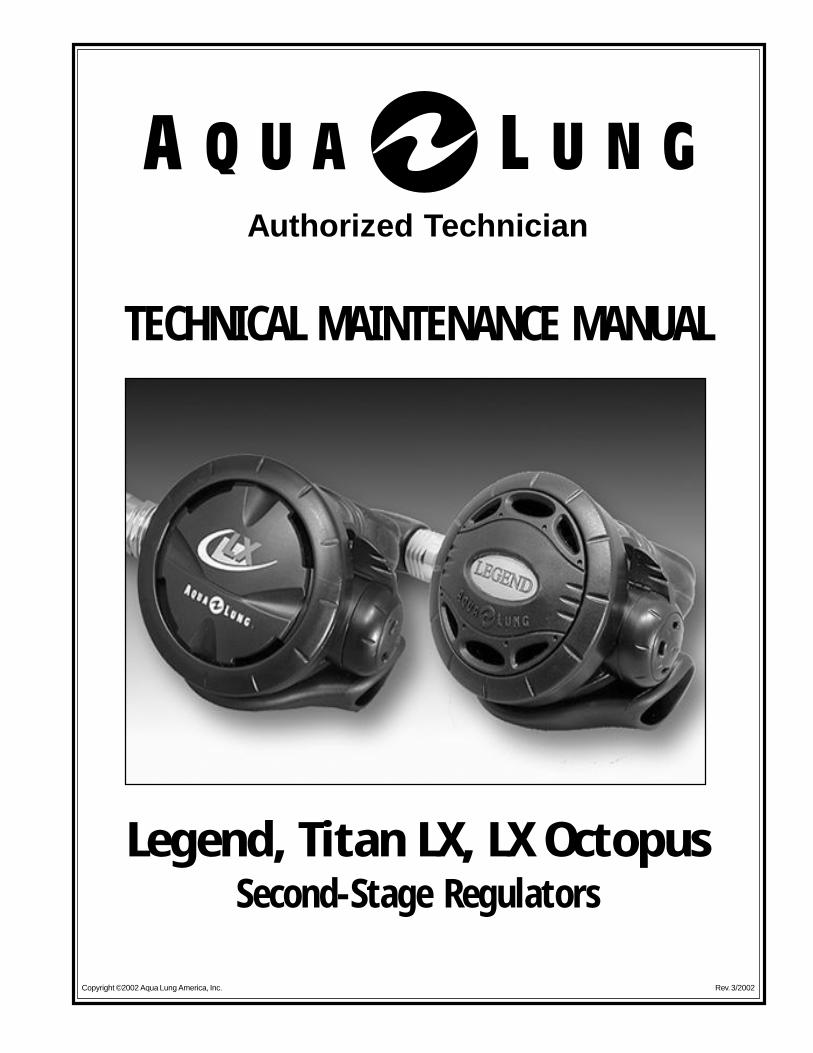
Contents
Introduction .......................................................................................... 1
Warnings, Cautions, & Notes .............................................................. 1
Scheduled Service .............................................................................. 1
General Guidelines ............................................................................. 1
Initial Inspection Procedure ................................................................ 2
Disassembly ........................................................................................ 3
Reassembly ........................................................................................ 7
Final Testing ........................................................................................ 11
Table 1 - Troubleshooting Guide ......................................................... 12
Table 2 - Recommended Tool List ...................................................... 13
Table 3 - Standard Parts Replacement Schedule ............................. 13
Table 4 - Torque Specifications ........................................................... 14
Table 5 - Test Bench Specifications.................................................... 14
Procedure A - Cleaning & Lubrication ................................................ 15
Table A - Recommended Lubricants & Cleaners .............................. 16
Exploded Parts Diagram ..................................................................... 17
Service Manual - Legend, Titan LX & LX Octopus Second-Stage Regulators
INTRODUCTION
This manual provides factory prescribed procedures for the service and repair of the Legend, Titan LX, andLX Octopus second-stage regulators. It is not intended to be used as an instructional manual for untrainedpersonnel. The procedures outlined within this manual are to be performed only by personnel who havereceived factory authorized training through a factory sponsored Aqua Lung Service & Repair Seminar.
If you do not completely understand all of the procedures outlined in this manual, contact Aqua Lung tospeak directly with a Technical Advisor before proceeding any further.
WARNINGS, CAUTIONS, & NOTES
Pay special attention to information provided in warnings, cautions, and notes that are accompanied by oneof these symbols:
A WARNING indicates a procedure or situation that may result in serious injury or death if instructionsare not followed correctly.
A CAUTION indicates any situation or technique that will result in potential damage to the product, orrender the product unsafe if instructions are not followed correctly.
A NOTE is used to emphasize important points, tips, and reminders.
SCHEDULED SERVICE
Regulators should be given the same care and maintenance as life support equipment. For normal orinfrequent use, the first and second stages should be inspected after one year, and fully serviced after twoyears. This yearly rotation of inspection and full service should continue for the life of the regulator.
NOTE: A unit that receives heavy or frequent use, such as in rental, instruction, or commercialapplications, should be serviced at least twice each year - or more often - depending on the conditionsof use and the manner in which it is maintained. (Refer to the care and maintenance proceduresoutlined in the Regulator Owner’s Manual.)
GENERAL GUIDELINES
1. In order to correctly perform the procedures outlined in this manual, it is important to follow each stepexactly in the order given. Read over the entire manual to become familiar with all procedures beforeattempting to disassemble or service the second-stage, and to learn which specialty tools and replacementparts will be required. Keep the manual open beside you for reference while performing each procedure.Do not rely on memory.
2. All service and repair should be carried out in a work area specifically set up and equipped for the task.Adequate lighting, cleanliness, and easy access to all required tools are essential for maintaining a profes-sional repair facility.
3. Before beginning any disassembly, it is important to first perform the Initial Inspection procedure, andrefer to "Table 1 - Troubleshooting" to determine the possible cause of any symptoms which may bepresent.
2 Legend & Titan LX Second Stage Service & Repair Manual
© 2002 Aqua Lung America, Inc.
INITIAL INSPECTION PROCEDURE
EXTERNAL INSPECTION1. Visually inspect the first-stage sintered filter to check for any signs that contaminants may have entered
the system, such as moisture, rust, aluminum oxide, or charcoal.
NOTE: A green discoloration positively indicates that moisture has entered the regulator, and inter-nal corrosion is therefore likely to be found in the first-stage. A white or rust colored residue usuallyindicates that the regulator has been used with a corroded aluminum or steel cylinder. Advise thecustomer of the proper methods for maintaining the regulator, and the possible need to obtain servicefor their cylinder.
2. Slide back the hose protector(s) to inspect the condition of the LP hose at its fittings and along its length.Check closely for any signs of blistering or abrasion, or corrosion of the fittings.
3. Inspect the condition of the mouthpiece to check for torn bite tabs, holes, or deterioration.
PRESSURE TEST
1. Prior to performing any disassembly, ensure that the second-stage is connected to a first-stage with astable intermediate pressure of 135±5 psi, with no open ports or hoses.
2. Listen closely to check for any signs of leakage from the second stage. If necessary, immerse the secondstage in water to locate the source of any leakage found and refer to "Table 1 - Troubleshooting" todetermine its possible cause.
CAUTION: If the second stage freeflows uncontrollably, immediately shut the cylinder valve andproceed directly to the Disassembly Procedure. Do not attempt to further inspect the regulator whilepressurized.
3. Depress the purge button to determine whether sufficient airflow is provided to clear the second stage ofwater. Immediately after releasing the purge button, listen closely to ensure that no air continues to flowfrom the second stage.
4. Turn the cylinder valve shut and depress the second stage purge button to depressurize the regulatorbefore proceeding to the following Disassembly Procedure.
4. As each individual regulator is disassembled, reusable components should be segregated to prevent themfrom mixing with nonreusable parts or parts from other regulators. Delicate parts, and those whichcontain critical sealing surfaces, must be protected and isolated from other parts to prevent damage duringthe cleaning procedure.
5. Use only genuine Aqua Lung parts purchased directly from Aqua Lung when servicing any Aqua Lungproduct. Substitution with another manufacturer’s parts constitutes an aftermarket modification of theproduct, and renders the original warranty null and void.
6. Do not attempt to reuse mandatory replacement parts under any circumstances, regardless of the amountof use the product has received since it was manufactured or last serviced.
7. When reassembling, it is important to follow every torque specification prescribed in this manual, using acalibrated torque wrench. Most parts are made of either marine brass or plastic, and can be permanentlydamaged by undue stress caused by overtightening.
Legend & Titan LX Stage Service & Repair Manual 3
© 2002 Aqua Lung America, Inc.
DISASSEMBLY
NOTE: Before performing any disassembly, refer to Table 3, which references all mandatory replace-ment parts. These parts must be replaced with new, and must not be reused under any circum-stances - regardless of the age of the regulator or how much use it has received since it was lastserviced.
CAUTION: To prevent damage to critical sealing surfaces, use only a plastic or brass o-ring removaltool (P/N 944022) when removing o-rings. Once an o-ring sealing surface has been damaged, thepart must be replaced with new in order to prevent the possibility of leakage. DO NOT use a dentalpick, or any other type of steel instrument.
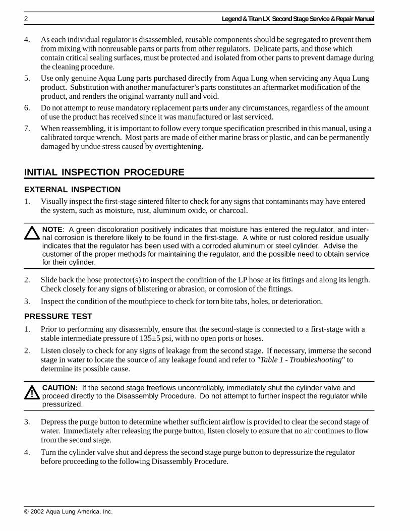
1. Using two 11/16" open-end wrenches, hold the retaining nut (13) stationary while removing the hose nutby turning it counterclockwise. See figure 1.
2. Remove o-ring (36) from the inside of the swivel nut on the hose. Exercise caution not to scratch the o-ring groove. Remove o-ring (32) from the threaded male end of the hose.
3. Pull back the two hose protectors (33 & 35) and inspect the hose crimps. The crimps should be free fromdamage. The hose should not be pulling out of the crimp. If it is, it must be replaced.
4. Using your hand, unscrew the purge cover retaining ring (1). Remove the purge cover (2).
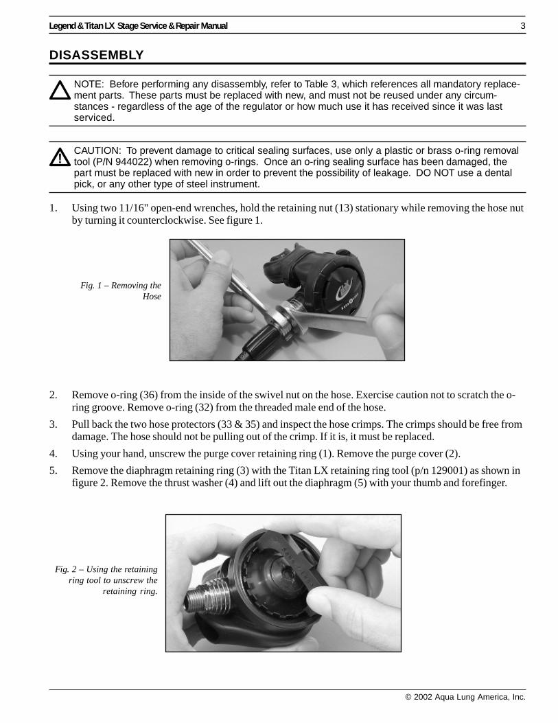
5. Remove the diaphragm retaining ring (3) with the Titan LX retaining ring tool (p/n 129001) as shown infigure 2. Remove the thrust washer (4) and lift out the diaphragm (5) with your thumb and forefinger.
Fig. 1 – Removing theHose
Fig. 2 – Using the retainingring tool to unscrew the
retaining ring.
4 Legend & Titan LX Second Stage Service & Repair Manual
© 2002 Aqua Lung America, Inc.
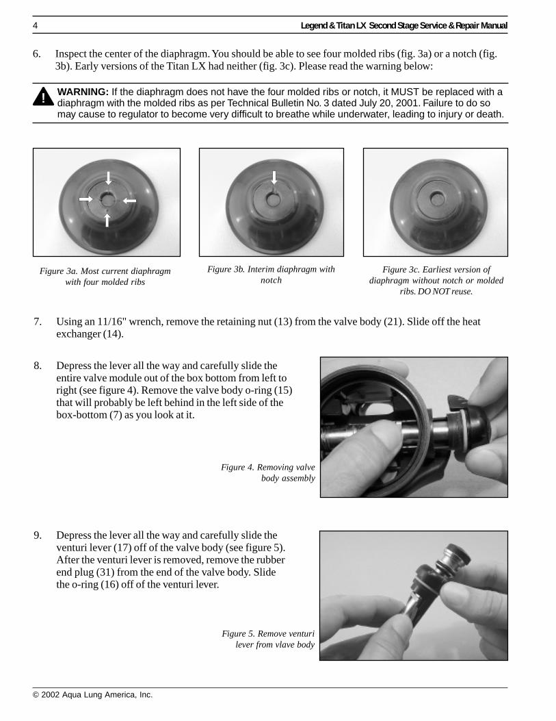
6. Inspect the center of the diaphragm. You should be able to see four molded ribs (fig. 3a) or a notch (fig.3b). Early versions of the Titan LX had neither (fig. 3c). Please read the warning below:
WARNING: If the diaphragm does not have the four molded ribs or notch, it MUST be replaced with adiaphragm with the molded ribs as per Technical Bulletin No. 3 dated July 20, 2001. Failure to do somay cause to regulator to become very difficult to breathe while underwater, leading to injury or death.
7. Using an 11/16" wrench, remove the retaining nut (13) from the valve body (21). Slide off the heatexchanger (14).
9. Depress the lever all the way and carefully slide theventuri lever (17) off of the valve body (see figure 5).After the venturi lever is removed, remove the rubberend plug (31) from the end of the valve body. Slidethe o-ring (16) off of the venturi lever.
8. Depress the lever all the way and carefully slide theentire valve module out of the box bottom from left toright (see figure 4). Remove the valve body o-ring (15)that will probably be left behind in the left side of thebox-bottom (7) as you look at it.
Figure 3a. Most current diaphragmwith four molded ribs
Figure 3b. Interim diaphragm withnotch
Figure 3c. Earliest version ofdiaphragm without notch or molded
ribs. DO NOT reuse.
Figure 4. Removing valvebody assembly
Figure 5. Remove venturilever from vlave body
Legend & Titan LX Stage Service & Repair Manual 5
© 2002 Aqua Lung America, Inc.
10. With a brass o-ring tool or small dowel, push out the locking pin (22). If the pin doesn’t push out easily,perhaps there is tension on it from the adjusting screw (30). In this case, turn the adjusting screw in onerevolution using a 4mm allen key for the metal screw or a 5mm allen key for the plastic screw.
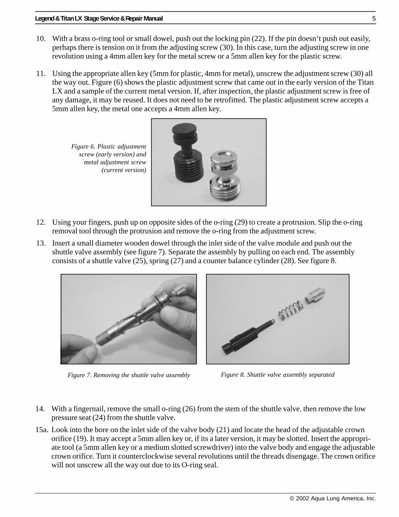
11. Using the appropriate allen key (5mm for plastic, 4mm for metal), unscrew the adjustment screw (30) allthe way out. Figure (6) shows the plastic adjustment screw that came out in the early version of the TitanLX and a sample of the current metal version. If, after inspection, the plastic adjustment screw is free ofany damage, it may be reused. It does not need to be retrofitted. The plastic adjustment screw accepts a5mm allen key, the metal one accepts a 4mm allen key.
12. Using your fingers, push up on opposite sides of the o-ring (29) to create a protrusion. Slip the o-ringremoval tool through the protrusion and remove the o-ring from the adjustment screw.
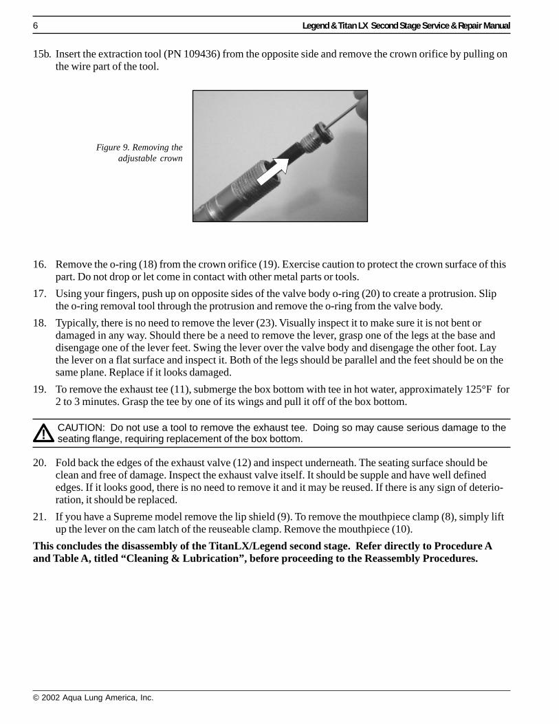
13. Insert a small diameter wooden dowel through the inlet side of the valve module and push out theshuttle valve assembly (see figure 7). Separate the assembly by pulling on each end. The assemblyconsists of a shuttle valve (25), spring (27) and a counter balance cylinder (28). See figure 8.
14. With a fingernail, remove the small o-ring (26) from the stem of the shuttle valve. then remove the lowpressure seat (24) from the shuttle valve.
15a. Look into the bore on the inlet side of the valve body (21) and locate the head of the adjustable crownorifice (19). It may accept a 5mm allen key or, if its a later version, it may be slotted. Insert the appropri-ate tool (a 5mm allen key or a medium slotted screwdriver) into the valve body and engage the adjustablecrown orifice. Turn it counterclockwise several revolutions until the threads disengage. The crown orificewill not unscrew all the way out due to its O-ring seal.
Figure 6. Plastic adjustmentscrew (early version) and
metal adjustment screw(current version)
Figure 7. Removing the shuttle valve assembly Figure 8. Shuttle valve assembly separated
6 Legend & Titan LX Second Stage Service & Repair Manual
© 2002 Aqua Lung America, Inc.
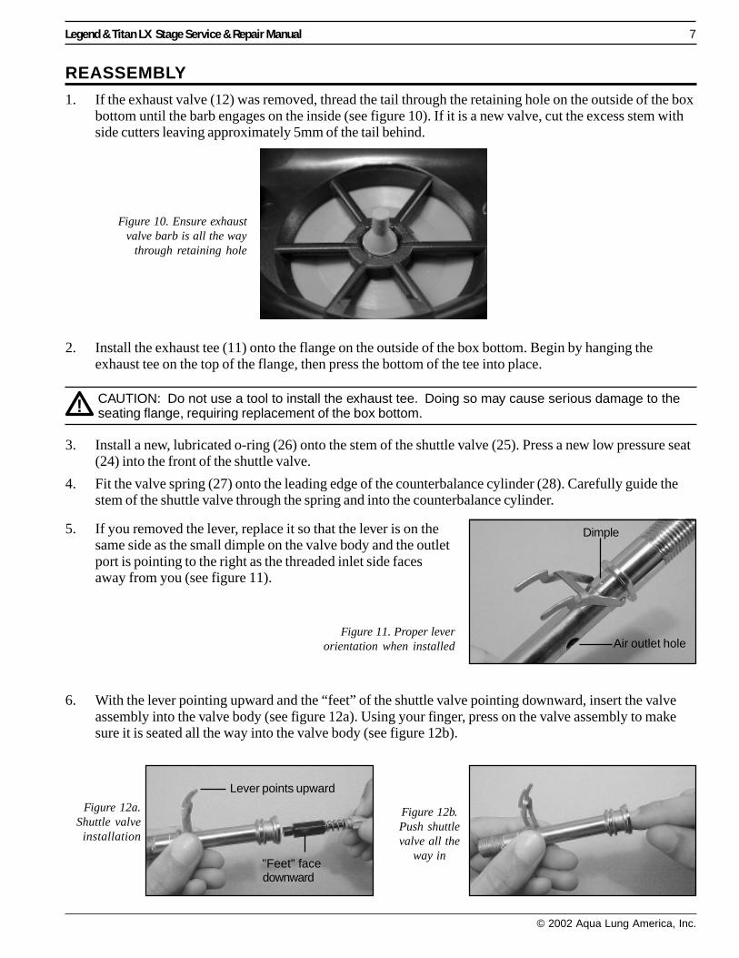
15b. Insert the extraction tool (PN 109436) from the opposite side and remove the crown orifice by pulling onthe wire part of the tool.
16. Remove the o-ring (18) from the crown orifice (19). Exercise caution to protect the crown surface of thispart. Do not drop or let come in contact with other metal parts or tools.
17. Using your fingers, push up on opposite sides of the valve body o-ring (20) to create a protrusion. Slipthe o-ring removal tool through the protrusion and remove the o-ring from the valve body.
18. Typically, there is no need to remove the lever (23). Visually inspect it to make sure it is not bent ordamaged in any way. Should there be a need to remove the lever, grasp one of the legs at the base anddisengage one of the lever feet. Swing the lever over the valve body and disengage the other foot. Laythe lever on a flat surface and inspect it. Both of the legs should be parallel and the feet should be on thesame plane. Replace if it looks damaged.
19. To remove the exhaust tee (11), submerge the box bottom with tee in hot water, approximately 125°F for2 to 3 minutes. Grasp the tee by one of its wings and pull it off of the box bottom.
CAUTION: Do not use a tool to remove the exhaust tee. Doing so may cause serious damage to theseating flange, requiring replacement of the box bottom.
20. Fold back the edges of the exhaust valve (12) and inspect underneath. The seating surface should beclean and free of damage. Inspect the exhaust valve itself. It should be supple and have well definededges. If it looks good, there is no need to remove it and it may be reused. If there is any sign of deterio-ration, it should be replaced.
21. If you have a Supreme model remove the lip shield (9). To remove the mouthpiece clamp (8), simply liftup the lever on the cam latch of the reuseable clamp. Remove the mouthpiece (10).
This concludes the disassembly of the TitanLX/Legend second stage. Refer directly to Procedure Aand Table A, titled “Cleaning & Lubrication”, before proceeding to the Reassembly Procedures.
Figure 9. Removing theadjustable crown
Legend & Titan LX Stage Service & Repair Manual 7
© 2002 Aqua Lung America, Inc.
REASSEMBLY
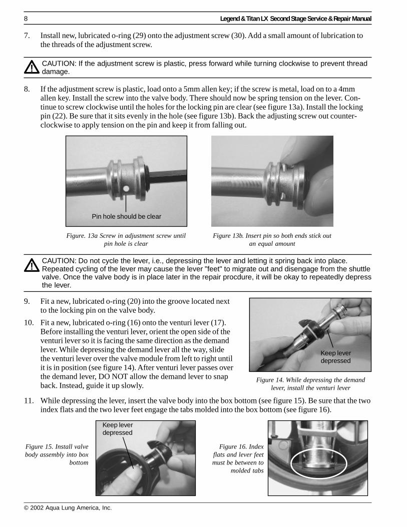
1. If the exhaust valve (12) was removed, thread the tail through the retaining hole on the outside of the boxbottom until the barb engages on the inside (see figure 10). If it is a new valve, cut the excess stem withside cutters leaving approximately 5mm of the tail behind.
Figure 10. Ensure exhaustvalve barb is all the way
through retaining hole
2. Install the exhaust tee (11) onto the flange on the outside of the box bottom. Begin by hanging theexhaust tee on the top of the flange, then press the bottom of the tee into place.
CAUTION: Do not use a tool to install the exhaust tee. Doing so may cause serious damage to theseating flange, requiring replacement of the box bottom.
3. Install a new, lubricated o-ring (26) onto the stem of the shuttle valve (25). Press a new low pressure seat(24) into the front of the shuttle valve.
4. Fit the valve spring (27) onto the leading edge of the counterbalance cylinder (28). Carefully guide thestem of the shuttle valve through the spring and into the counterbalance cylinder.
Figure 11. Proper leverorientation when installed
Dimple
Air outlet hole
6. With the lever pointing upward and the “feet” of the shuttle valve pointing downward, insert the valveassembly into the valve body (see figure 12a). Using your finger, press on the valve assembly to makesure it is seated all the way into the valve body (see figure 12b).
5. If you removed the lever, replace it so that the lever is on thesame side as the small dimple on the valve body and the outletport is pointing to the right as the threaded inlet side facesaway from you (see figure 11).
Figure 12a.Shuttle valve
installation
Figure 12b.Push shuttlevalve all the
way in"Feet" facedownward
Lever points upward
8 Legend & Titan LX Second Stage Service & Repair Manual
© 2002 Aqua Lung America, Inc.
7. Install new, lubricated o-ring (29) onto the adjustment screw (30). Add a small amount of lubrication tothe threads of the adjustment screw.
CAUTION: If the adjustment screw is plastic, press forward while turning clockwise to prevent threaddamage.
8. If the adjustment screw is plastic, load onto a 5mm allen key; if the screw is metal, load on to a 4mmallen key. Install the screw into the valve body. There should now be spring tension on the lever. Con-tinue to screw clockwise until the holes for the locking pin are clear (see figure 13a). Install the lockingpin (22). Be sure that it sits evenly in the hole (see figure 13b). Back the adjusting screw out counter-clockwise to apply tension on the pin and keep it from falling out.
Figure. 13a Screw in adjustment screw untilpin hole is clear
Figure 13b. Insert pin so both ends stick outan equal amount
CAUTION: Do not cycle the lever, i.e., depressing the lever and letting it spring back into place.Repeated cycling of the lever may cause the lever "feet" to migrate out and disengage from the shuttlevalve. Once the valve body is in place later in the repair procdure, it will be okay to repeatedly depressthe lever.
Figure 14. While depressing the demandlever, install the venturi lever
Pin hole should be clear
Keep leverdepressed
11. While depressing the lever, insert the valve body into the box bottom (see figure 15). Be sure that the twoindex flats and the two lever feet engage the tabs molded into the box bottom (see figure 16).
Keep leverdepressed
Figure 15. Install valvebody assembly into box
bottom
Figure 16. Indexflats and lever feetmust be between to
molded tabs
9. Fit a new, lubricated o-ring (20) into the groove located nextto the locking pin on the valve body.
10. Fit a new, lubricated o-ring (16) onto the venturi lever (17).Before installing the venturi lever, orient the open side of theventuri lever so it is facing the same direction as the demandlever. While depressing the demand lever all the way, slidethe venturi lever over the valve module from left to right untilit is in position (see figure 14). After venturi lever passes overthe demand lever, DO NOT allow the demand lever to snapback. Instead, guide it up slowly.
Legend & Titan LX Stage Service & Repair Manual 9
© 2002 Aqua Lung America, Inc.
12. Slide a new, lubricated o-ring (15) down the threaded end of the valve body, into the box bottom. Slidethe heat exchanger (14), large diameter first, down the valve body. Thread on the retaining nut (13) untilfinger tight. Using an 11/16" crows foot or deep socket, apply a torque to the nut of 45 +/-2 inch-lbs.
13. Turn in the adjustment screw (30) a half turn for the standard Titan LX and Legend, or one full turn forthe Titan LX Supreme, Legend Supreme and Octopus LX.
14. Fit a new, lubricated o-ring (18) onto the adjustable crown (19). Press the adjustable crown, threaded endfirst, into the valve body. Insert a 5mm hex key or medium blade screwdriver (depending on the style ofadjustable crown) into the adjustable crown. Push the adjustable crown into the valve body as far as itwill go.
15. While holding the rim of the box bottom at eye level, turn the adjustable crown orifice in (clockwise)until the lever just begins to drop. At this point the crown orifice has made contact with the rubber seat-ing. This is a preliminary setting.
16. Add a new o-ring (32) to the male end of the medium pressure hose. Install a new, lubricated o-ring (36)to the female end of the hose.
CAUTION: Prior to adjusting the lever height, the accompanying first stage must be correctly ser-viced, adjusted to a stable intermediate pressure of 135±5 psi, and fully tested.
17. Adjust the lever height
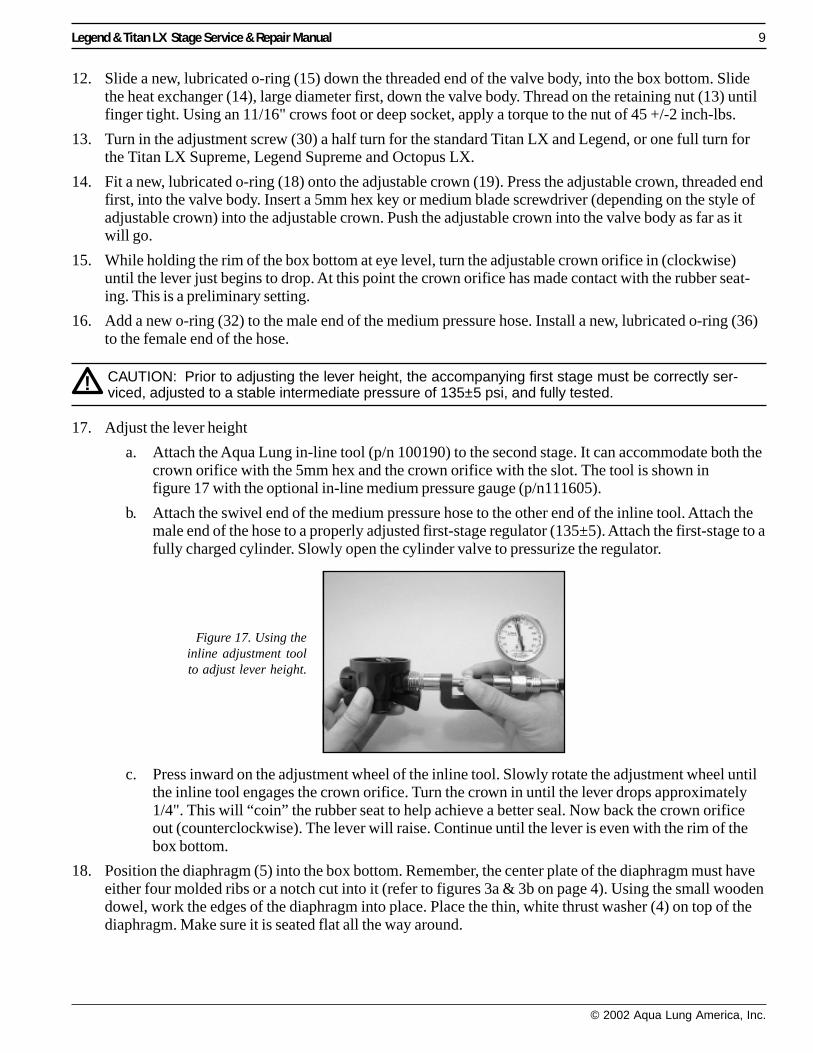
a. Attach the Aqua Lung in-line tool (p/n 100190) to the second stage. It can accommodate both thecrown orifice with the 5mm hex and the crown orifice with the slot. The tool is shown infigure 17 with the optional in-line medium pressure gauge (p/n111605).
b. Attach the swivel end of the medium pressure hose to the other end of the inline tool. Attach themale end of the hose to a properly adjusted first-stage regulator (135±5). Attach the first-stage to afully charged cylinder. Slowly open the cylinder valve to pressurize the regulator.
c. Press inward on the adjustment wheel of the inline tool. Slowly rotate the adjustment wheel untilthe inline tool engages the crown orifice. Turn the crown in until the lever drops approximately1/4". This will “coin” the rubber seat to help achieve a better seal. Now back the crown orificeout (counterclockwise). The lever will raise. Continue until the lever is even with the rim of thebox bottom.
18. Position the diaphragm (5) into the box bottom. Remember, the center plate of the diaphragm must haveeither four molded ribs or a notch cut into it (refer to figures 3a & 3b on page 4). Using the small woodendowel, work the edges of the diaphragm into place. Place the thin, white thrust washer (4) on top of thediaphragm. Make sure it is seated flat all the way around.
Figure 17. Using theinline adjustment toolto adjust lever height.
Optional IP Gauge
Adjustment wheel
Lever evenwith rim
10 Legend & Titan LX Second Stage Service & Repair Manual
© 2002 Aqua Lung America, Inc.
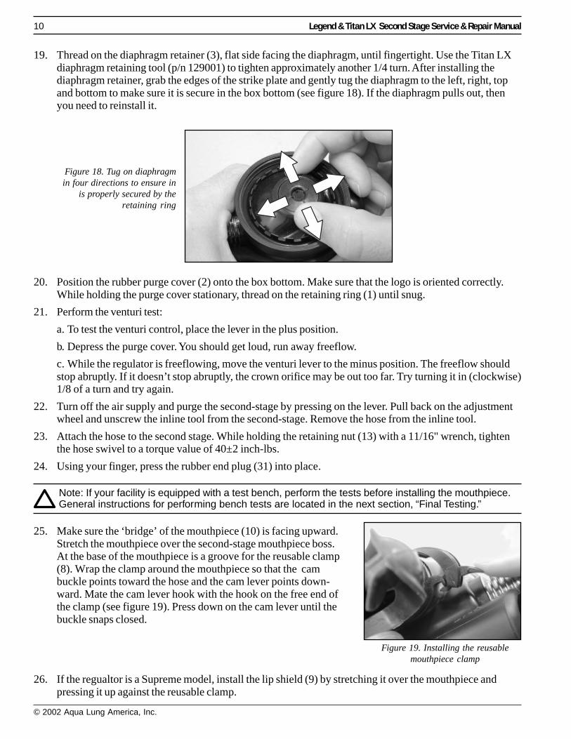
19. Thread on the diaphragm retainer (3), flat side facing the diaphragm, until fingertight. Use the Titan LXdiaphragm retaining tool (p/n 129001) to tighten approximately another 1/4 turn. After installing thediaphragm retainer, grab the edges of the strike plate and gently tug the diaphragm to the left, right, topand bottom to make sure it is secure in the box bottom (see figure 18). If the diaphragm pulls out, thenyou need to reinstall it.
Figure 18. Tug on diaphragmin four directions to ensure in
is properly secured by theretaining ring
20. Position the rubber purge cover (2) onto the box bottom. Make sure that the logo is oriented correctly.While holding the purge cover stationary, thread on the retaining ring (1) until snug.
21. Perform the venturi test:
a. To test the venturi control, place the lever in the plus position.
b. Depress the purge cover. You should get loud, run away freeflow.
c. While the regulator is freeflowing, move the venturi lever to the minus position. The freeflow shouldstop abruptly. If it doesn’t stop abruptly, the crown orifice may be out too far. Try turning it in (clockwise)1/8 of a turn and try again.
22. Turn off the air supply and purge the second-stage by pressing on the lever. Pull back on the adjustmentwheel and unscrew the inline tool from the second-stage. Remove the hose from the inline tool.
23. Attach the hose to the second stage. While holding the retaining nut (13) with a 11/16" wrench, tightenthe hose swivel to a torque value of 40±2 inch-lbs.
24. Using your finger, press the rubber end plug (31) into place.
Note: If your facility is equipped with a test bench, perform the tests before installing the mouthpiece.General instructions for performing bench tests are located in the next section, “Final Testing.”
25. Make sure the ‘bridge’ of the mouthpiece (10) is facing upward.Stretch the mouthpiece over the second-stage mouthpiece boss.At the base of the mouthpiece is a groove for the reusable clamp(8). Wrap the clamp around the mouthpiece so that the cambuckle points toward the hose and the cam lever points down-ward. Mate the cam lever hook with the hook on the free end ofthe clamp (see figure 19). Press down on the cam lever until thebuckle snaps closed.
26. If the regualtor is a Supreme model, install the lip shield (9) by stretching it over the mouthpiece andpressing it up against the reusable clamp.
Figure 19. Installing the reusablemouthpiece clamp
Legend & Titan LX Stage Service & Repair Manual 11
© 2002 Aqua Lung America, Inc.
FINAL TESTING
SECOND STAGE OPENING EFFORT TEST
1. Connect the first stage regulator to a calibrated test bench and pressurize the system to 3000 (±100) psi.Slowly open the flowmeter control knob (start vacuum) while watching both the magnahelic gauge andthe intermediate pressure gauge.
2. When the intermediate pressure begins to drop, indicating the second-stage valve is open, the magnahelicgauge should indicate an opening effort of +0.8" to +1.4" of H2O for a standard 2nd-stage, or +1.1" to+1.7" of H2O for the supreme or octopus 2nd-stage. If the reading exceeds these specifications, refer torefer to “Table 1 - Troubleshooting” for corrective actions.
SECOND STAGE AIR FLOW TEST
1. Slowly turn the flowmeter control knob until the flow reaches a minimum of 15 SCFM (425 liters perminute). The reading on the Magnahelic gauge (inhalation / exhalation effort gauge) should indicate nomore than +6.O” H2O. If the reading exceeds +6.0" H2O, refer to refer to “Table 1 - Troubleshooting”for corrective actions.
SECOND STAGE PURGE FLOW TEST
1. Turn off the flowmeter control knob. Next, while the second stage is still mounted on the mouthpieceadapter, watch the flowmeter gauge and depress the purge button until the second stage valve is com-pletely open. The flowmeter gauge must indicate a minimum of +5.0 SCFM (142 Liters per minute.). Ifthe purge flow is less than +5.0 SCFM, refer to “Table 1 - Troubleshooting.”
2. When purge flow is correct, remove the second-stage from the mouthpiece adapter on the flow testbench. Shut the valve of the test bench, and purge the second stage to depressurize the system. Removethe regulator.
EXTERNAL LEAK TEST
1. After disconnecting the regulator from the flow bench, connect it to a scuba cylinder filled to approxi-mately 3,000 psi. Open the cylinder valve to repressurize the regulator, and submerge the entire systemin a test tank of clean water.
2. Observe any bubbles arising from the submerged regulator over a one minute period. The recommendedtime is necessary due to slower bubble formation that occurs in smaller leaks. Bubbles indicate a leak,which requires that the system must be disassembled at the source to check sealing surfaces, assemblysequence and component positioning in order to correct the problem(s).
NOTE: Extremely small leaks may be better detected by applying a soap solution or Snoop™ to theleak area. Bubble streams will indicate the source of the leak. Before disassembling to correct anyleaks, rinse the entire regulator thoroughly with fresh water and blow out all residual moisture withfiltered, low-pressure (50 psi) air. Disassemble and remedy the problem, referring to “Table 1 -Troubleshooting.”
SUBJECTIVE BREATHING TEST
1. Depress the purge cover fully to ensure that an adequate volume of air needed to clear the second stageflows through the mouthpiece. Then, inhale slowly but deeply from the mouthpiece. A properly ser-viced and adjusted regulator should deliver air upon deep inhalation without excessive inhalation effort,freeflow, or “fluttering” of the second-stage diaphragm. When exhaling, there should be no fluttering orsticking of the exhalation valve. If any of these problems occur, refer to Table 1 - Troubleshooting.
This concludes annual service procedures.
12 Legend & Titan LX Second Stage Service & Repair Manual
© 2002 Aqua Lung America, Inc.
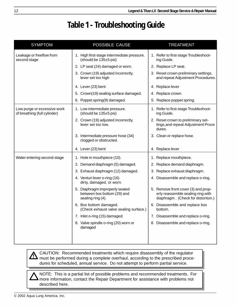
Table 1 - Troubleshooting Guide
SYMPTOM POSSIBLE CAUSE TREATMENT
CAUTION: Recommended treatments which require disassembly of the regulatormust be performed during a complete overhaul, according to the prescribed proce-dures for scheduled, annual service. Do not attempt to perform partial service.
Leakage or freeflow from 1. High first-stage intermediate pressure. 1. Refer to first-stage Troubleshoot-second stage (should be 135±5 psi) ing Guide.
2. LP seat (24) damaged or worn. 2. Replace LP seat.
3. Crown (19) adjusted incorrectly, 3. Reset crown preliminary settings,lever set too high and repeat Adjustment Procedures.
4. Lever (23) bent 4. Replace lever
5. Crown(19) sealing surface damaged. 4. Replace crown.
6. Poppet spring(9) damaged. 5. Replace poppet spring.
Low purge or excessive work 1. Low intermediate pressure. 1. Refer to first-stage Troubleshoot-of breathing (full cylinder) (should be 135±5 psi) ing Guide.
2. Crown (19) adjusted incorrectly, 2. Reset crown to preliminary set-lever set too low. tings,and repeat Adjustment Proce
dures.
3. Intermediate pressure hose (34) 3. Clean or replace hose.clogged or obstructed.
4. Lever (23) bent 4. Replace lever
Water entering second-stage 1. Hole in mouthpiece (10). 1. Replace mouthpiece.
2. Demand diaphragm (5) damaged. 2. Replace demand diaphragm.
3. Exhaust diaphragm (12) damaged. 3. Replace exhaust diaphragm.
4. Venturi lever o-ring (16) 4. Disassemble and replace o-ring.dirty, damaged, or worn.
5. Diaphragm improperly seated 5. Remove front cover (3) and prop-between box bottom (29) and erly reassemble sealing ring withsealing ring (4). diaphragm . (Check for distortion.)
6. Box bottom damaged. 6. Disassemble and replace box(Check exhaust valve sealing surface.) bottom.
7. Inlet o-ring (15) damaged. 7. Disassemble and replace o-ring.
8. Valve spindle o-ring (20) worn or 8. Disassemble and replace o-ring.damaged
NOTE: This is a partial list of possible problems and recommended treatments. Formore information, contact the Repair Department for assistance with problems notdescribed here.
Legend & Titan LX Stage Service & Repair Manual 13
© 2002 Aqua Lung America, Inc.
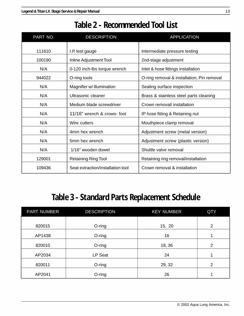
Table 2 - Recommended Tool List
Table 3 - Standard Parts Replacement Schedule
PART NUMBER DESCRIPTION KEY NUMBER QTY
820015 O-ring 15, 20 2
AP1438 O-ring 16 1
820010 O-ring 18, 36 2
AP2034 LP Seat 24 1
820011 O-ring 29, 32 2
AP2041 O-ring 26 1
PART NO. DESCRIPTION APPLICATION
111610 I.P. test gauge Intermediate pressure testing
100190 Inline Adjustment Tool 2nd-stage adjustment
N/A 0-120 inch-lbs torque wrench Inlet & hose fittings installation
944022 O-ring tools O-ring removal & installation, Pin removal
N/A Magnifier w/ illumination Sealing surface inspection
N/A Ultrasonic cleaner Brass & stainless steel parts cleaning
N/A Medium blade screwdriver Crown removal/ installation
N/A 11/16" wrench & crows- foot IP hose fitting & Retaining nut
N/A Wire cutters Mouthpiece clamp removal
N/A 4mm hex wrench Adjustment screw (metal version)
N/A 5mm hex wrench Adjustment screw (plastic version)
N/A 1/16" wooden dowel Shuttle valve removal
129001 Retaining Ring Tool Retaining ring removal/installation
109436 Seat extraction/installation tool Crown removal & installation
14 Legend & Titan LX Second Stage Service & Repair Manual
© 2002 Aqua Lung America, Inc.
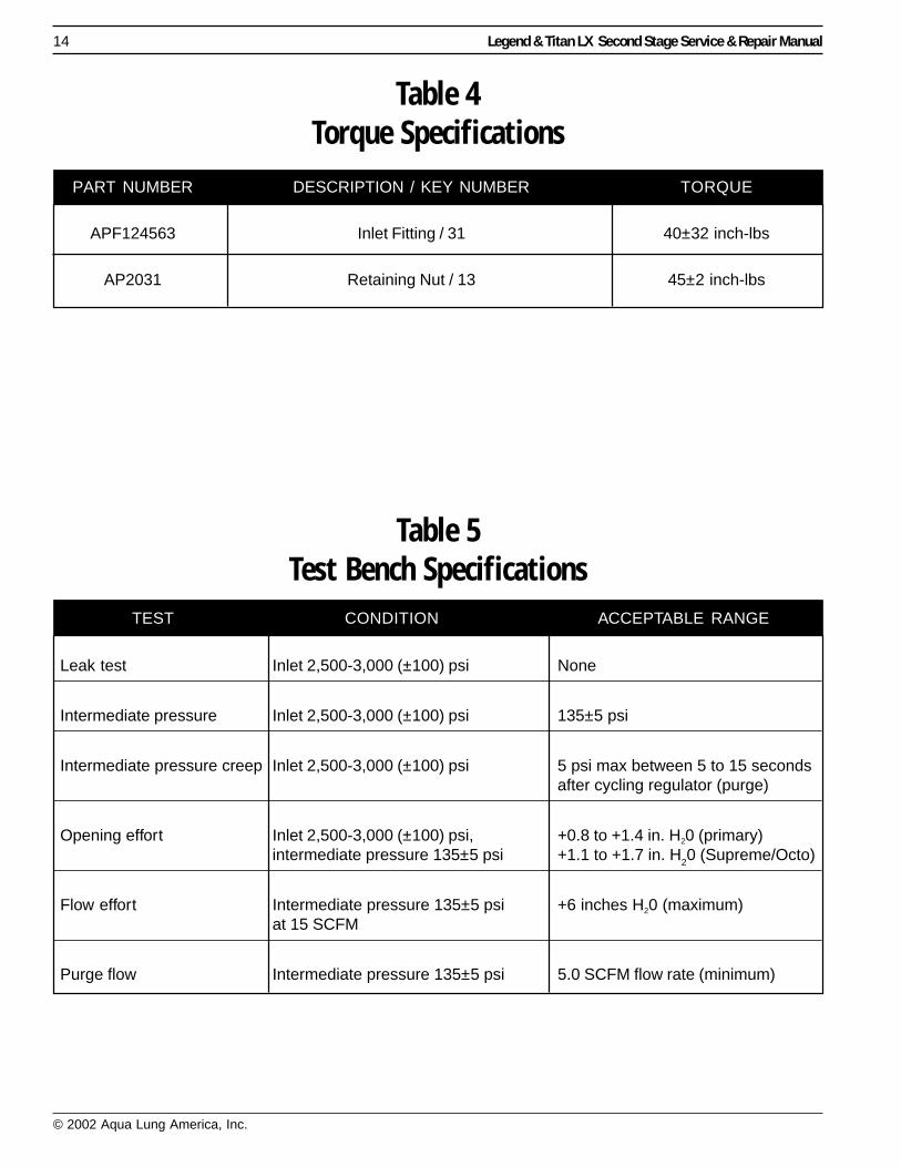
Table 4Torque Specifications
PART NUMBER DESCRIPTION / KEY NUMBER TORQUE
APF124563 Inlet Fitting / 31 40±32 inch-lbs
AP2031 Retaining Nut / 13 45±2 inch-lbs
Table 5Test Bench Specifications
TEST CONDITION ACCEPTABLE RANGE
Leak test Inlet 2,500-3,000 (±100) psi None
Intermediate pressure Inlet 2,500-3,000 (±100) psi 135±5 psi
Intermediate pressure creep Inlet 2,500-3,000 (±100) psi 5 psi max between 5 to 15 secondsafter cycling regulator (purge)
Opening effort Inlet 2,500-3,000 (±100) psi, +0.8 to +1.4 in. H20 (primary)intermediate pressure 135±5 psi +1.1 to +1.7 in. H20 (Supreme/Octo)
Flow effort Intermediate pressure 135±5 psi +6 inches H20 (maximum)at 15 SCFM
Purge flow Intermediate pressure 135±5 psi 5.0 SCFM flow rate (minimum)
Legend & Titan LX Stage Service & Repair Manual 15
© 2002 Aqua Lung America, Inc.
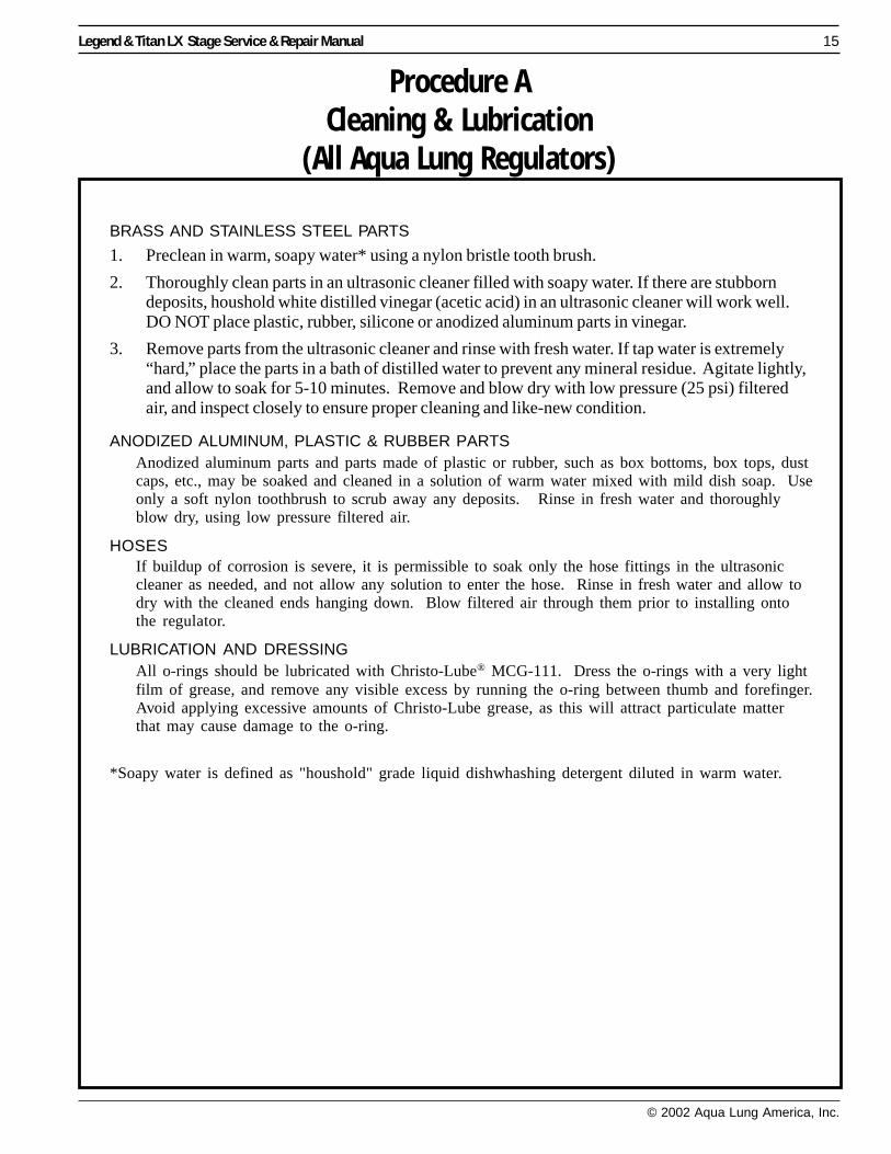
BRASS AND STAINLESS STEEL PARTS
1. Preclean in warm, soapy water* using a nylon bristle tooth brush.
2. Thoroughly clean parts in an ultrasonic cleaner filled with soapy water. If there are stubborndeposits, houshold white distilled vinegar (acetic acid) in an ultrasonic cleaner will work well.DO NOT place plastic, rubber, silicone or anodized aluminum parts in vinegar.
3. Remove parts from the ultrasonic cleaner and rinse with fresh water. If tap water is extremely“hard,” place the parts in a bath of distilled water to prevent any mineral residue. Agitate lightly,and allow to soak for 5-10 minutes. Remove and blow dry with low pressure (25 psi) filteredair, and inspect closely to ensure proper cleaning and like-new condition.
ANODIZED ALUMINUM, PLASTIC & RUBBER PARTSAnodized aluminum parts and parts made of plastic or rubber, such as box bottoms, box tops, dustcaps, etc., may be soaked and cleaned in a solution of warm water mixed with mild dish soap. Useonly a soft nylon toothbrush to scrub away any deposits. Rinse in fresh water and thoroughlyblow dry, using low pressure filtered air.
HOSESIf buildup of corrosion is severe, it is permissible to soak only the hose fittings in the ultrasoniccleaner as needed, and not allow any solution to enter the hose. Rinse in fresh water and allow todry with the cleaned ends hanging down. Blow filtered air through them prior to installing ontothe regulator.
LUBRICATION AND DRESSINGAll o-rings should be lubricated with Christo-Lube® MCG-111. Dress the o-rings with a very lightfilm of grease, and remove any visible excess by running the o-ring between thumb and forefinger.Avoid applying excessive amounts of Christo-Lube grease, as this will attract particulate matterthat may cause damage to the o-ring.
*Soapy water is defined as "houshold" grade liquid dishwhashing detergent diluted in warm water.
Procedure ACleaning & Lubrication
(All Aqua Lung Regulators)
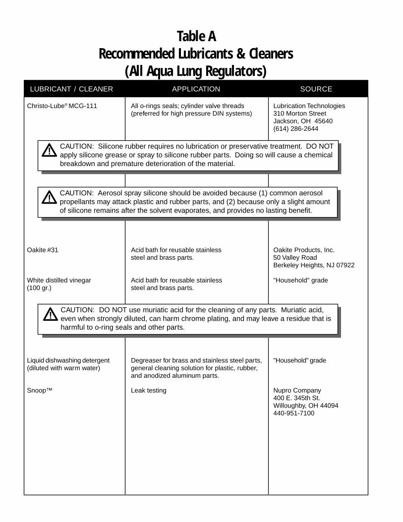
LUBRICANT / CLEANER APPLICATION SOURCE
Christo-Lube® MCG-111 All o-rings seals; cylinder valve threads Lubrication Technologies(preferred for high pressure DIN systems) 310 Morton Street
Jackson, OH 45640(614) 286-2644
Oakite #31 Acid bath for reusable stainless Oakite Products, Inc.steel and brass parts. 50 Valley Road
Berkeley Heights, NJ 07922
White distilled vinegar Acid bath for reusable stainless "Household" grade(100 gr.) steel and brass parts.
Liquid dishwashing detergent Degreaser for brass and stainless steel parts, "Household" grade(diluted with warm water) general cleaning solution for plastic, rubber,
and anodized aluminum parts.
Snoop™ Leak testing Nupro Company400 E. 345th St.Willoughby, OH 44094440-951-7100
Table ARecommended Lubricants & Cleaners
(All Aqua Lung Regulators)
CAUTION: DO NOT use muriatic acid for the cleaning of any parts. Muriatic acid,even when strongly diluted, can harm chrome plating, and may leave a residue that isharmful to o-ring seals and other parts.
CAUTION: Silicone rubber requires no lubrication or preservative treatment. DO NOTapply silicone grease or spray to silicone rubber parts. Doing so will cause a chemicalbreakdown and premature deterioration of the material.
CAUTION: Aerosol spray silicone should be avoided because (1) common aerosolpropellants may attack plastic and rubber parts, and (2) because only a slight amountof silicone remains after the solvent evaporates, and provides no lasting benefit.
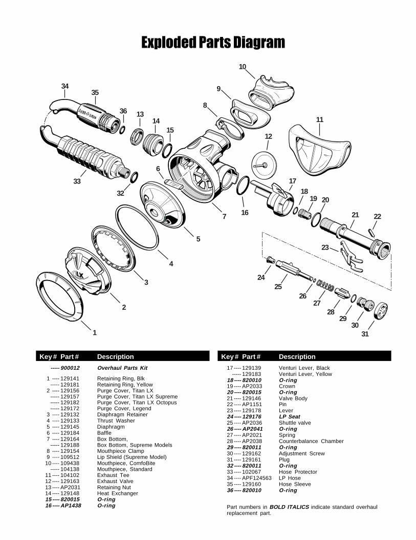
----- 900012 Overhaul Parts Kit
1 ---- 129141 Retaining Ring, Blk----- 129181 Retaining Ring, Yellow
2 ---- 129156 Purge Cover, Titan LX----- 129157 Purge Cover, Titan LX Supreme----- 129182 Purge Cover, Titan LX Octopus----- 129172 Purge Cover, Legend
3 ---- 129132 Diaphragm Retainer4 ---- 129133 Thrust Washer5 ---- 129145 Diaphragm6 ---- 129184 Baffle7 ---- 129164 Box Bottom,
----- 129188 Box Bottom, Supreme Models8 ---- 129154 Mouthpiece Clamp9 ---- 109512 Lip Shield (Supreme Model)
10 ---- 109438 Mouthpiece, ComfoBite----- 104138 Mouthpiece, Standard
11 ---- 104102 Exhaust Tee12 ---- 129163 Exhaust Valve13 ---- AP2031 Retaining Nut14 ---- 129148 Heat Exchanger15 ---- 820015 O-ring16 ---- AP1438 O-ring
17 ---- 129139 Venturi Lever, Black----- 129183 Venturi Lever, Yellow
18 ---- 820010 O-ring19 ---- AP2033 Crown20 ---- 820015 O-ring21 ---- 129146 Valve Body22 ---- AP1151 Pin23 ---- 129178 Lever24 ---- 129176 LP Seat25 ---- AP2036 Shuttle valve26 ---- AP2041 O-ring27 ---- AP2021 Spring28 ---- AP2038 Counterbalance Chamber29 ---- 820011 O-ring30 ---- 129162 Adjustment Screw31 ---- 129161 Plug32 ---- 820011 O-ring33 ---- 102067 Hose Protector34 ---- APF124563 LP Hose35 ---- 129160 Hose Sleeve36 ---- 820010 O-ring
Part numbers in BOLD ITALICS indicate standard overhaulreplacement part.
Key # Part # Description Key # Part # Description
1
2
3
4
5
6
8
9
10
11
12
1314
15
16
1718
19 20
21 22
23
2425
2627
2829
3031
32
33
3435
36
7
����������� ������
2340 COUSTEAU COURT
VISTA, CA 92083
WWW.AQUALUNG.COM