Embed Size (px)
Citation preview
.
AQUA GLIDER
-- A SCUBA Mobility Solution --
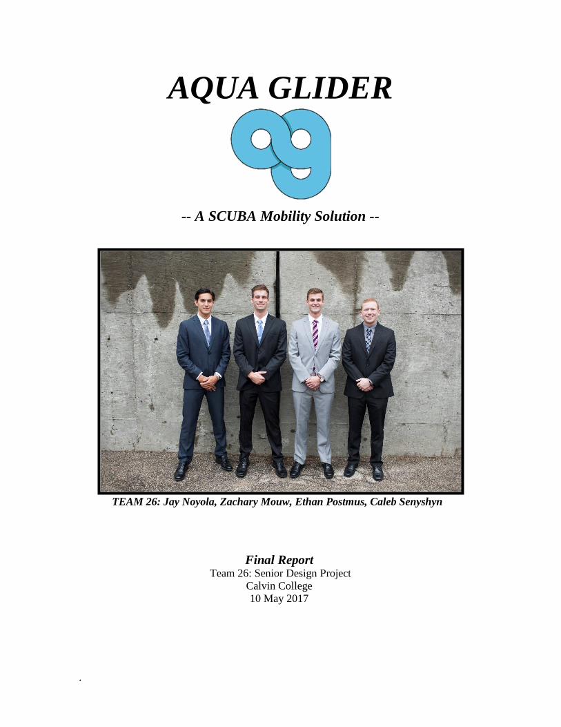
TEAM 26: Jay Noyola, Zachary Mouw, Ethan Postmus, Caleb Senyshyn
Final Report Team 26: Senior Design Project
Calvin College
10 May 2017
.
© 2017
Calvin College and Jay Noyola, Zachary Mouw, Ethan Postmus and Caleb Senyshyn
i
EXECUTIVE SUMMARY
Through the course of ancient history, the seas and its depths were venerated for their immense power and
great mystery. However, the exploration of its depths were unable to be explored effectively until the
development of the self-contained underwater breathing apparatus or SCUBA in the mid-twentieth century.
Since, there have been many innovative improvements to enhance the SCUBA experience, including the
relatively recent developments of the diver propulsion vehicle (DPV). DPV’s have been designed to
conserve a diver’s air supply while allowing for faster and more efficient movement underwater. Senior design Team 26 believes that there is space in the market for a more innovative and technologically
advanced recreational DPV. The goal of this project is to develop a DPV that helps fill such a space through
a SCUBA mobility solution called the Aqua Glider. While the Aqua Glider will maintain an electric motor
driven propeller system, it was designed to achieve higher speeds with the capability of higher mobility
control than many of the traditional designs. The Aqua Glider was designed to achieve speeds up to 5 mph
and accommodate the mobility desires of recreational dives. With a new hydrodynamic shape and system
arrangement that resembles that of a stingray (which includes a fiberglass body, and a dual propeller
system), the team set out to meet these innovative goals. The scope of the project included the design and
production of a prototype of the Aqua Glider that served as a proof of concept. The team completed the
project in the time frame and budget dictated by the ENGR 339/340 course. The first half of the project honed in on the planning and feasibility of the Aqua Glider concept. After
conceptual research and design the team decided that the Aqua Glider was a feasible concept and decided to
move forward with prototyping. The team spent the second half of the year finalizing a design for the Aqua
Glider and then constructing a prototype. Testing revealed that the Aqua Glider design was easily
maneuverable and controlled, nearly neutrally buoyant, and did not acquire any leaks that were fatal to
testing. Additionally, the Aqua Glider achieved an underwater speed of 3 mph pulling an adult diver
wearing basic SCUBA gear. Therefore, team 26 believes they have successfully delivered an innovative
product to equip divers to efficiently explore the underwater world—a world full of life, history, meaning
and God’s beauty.
ii
TABLE OF CONTENTS
1. Introduction ................................................................................................................................................... 1
1.1 The Motivation ........................................................................................................................................ 1
1.2 Context .................................................................................................................................................... 1
1.3 Problem Definition .................................................................................................................................. 1
1.4 Team Members ........................................................................................................................................ 2
1.4.1 Ethan Postmus .................................................................................................................................. 2
1.4.2 Zachary Mouw.................................................................................................................................. 2
1.4.3 Jay Noyola ........................................................................................................................................ 2
1.4.4 Caleb Senyshyn ................................................................................................................................ 2
2. Project Management ..................................................................................................................................... 3
2.1 Team Organization .................................................................................................................................. 3
2.2 Project Breakdown .................................................................................................................................. 3
2.2.1 Power ................................................................................................................................................ 3
2.2.2 Buoyancy .......................................................................................................................................... 3
2.2.3 Hydrodynamics................................................................................................................................. 4
2.2.4 Controls ............................................................................................................................................ 4
2.2.5 Waterproofing................................................................................................................................... 4
2.3 Schedule .................................................................................................................................................. 4
2.4 Method of Approach ............................................................................................................................... 5
3. Requirements & Specifications .................................................................................................................... 6
3.1 Operation ................................................................................................................................................. 6
3.1.1 Speed ................................................................................................................................................ 6
3.1.2 Size & Weight .................................................................................................................................. 6
3.1.3 Battery & Run Time ......................................................................................................................... 6
3.1.4 Buoyancy .......................................................................................................................................... 6
3.1.5 Navigational Control ........................................................................................................................ 7
3.1.6 Waterproof & Structure .................................................................................................................... 7
3.2 Aesthetics ................................................................................................................................................ 7
3.3 Safety ...................................................................................................................................................... 7
3.3.1 Key Safety Considerations ............................................................................................................... 7
3.3.2 Additional Safety Considerations ..................................................................................................... 8
3.3.3 Risk Assessment ............................................................................................................................... 8
4. Design Alternatives and Selection ................................................................................................................ 9
4.1 Power ...................................................................................................................................................... 9
4.1.1 Design Research (Battery) ................................................................................................................ 9
4.1.2 Design Considerations & Alt. .......................................................................................................... 9
4.1.3 Design Decisions .............................................................................................................................. 9
4.1.4 Design Research (Motors & Propellers) ......................................................................................... 11
4.1.5 Design Considerations & Alt. ........................................................................................................ 11
4.1.6 Design Decisions ............................................................................................................................ 11
4.2 Bouyancy............................................................................................................................................... 12
4.2.1 Design Research ............................................................................................................................. 12
4.2.2 Design Considerations & Alt. ........................................................................................................ 13
4.2.3 Design Decisions ............................................................................................................................ 13
4.3 Hydrodynamics ..................................................................................................................................... 14
iii
4.3.1 Design Research ............................................................................................................................. 14
4.3.2 Design Considerations & Alt. ........................................................................................................ 15
4.3.3 Design Decisions ............................................................................................................................ 15
4.4 Material & Waterproof .......................................................................................................................... 15
4.4.1 Design Research ............................................................................................................................. 15
4.4.2 Design Considerations & Alt. ........................................................................................................ 16
4.4.3 Design Decisions ............................................................................................................................ 16
4.5 Controls ................................................................................................................................................. 17
4.5.1 Design Research ............................................................................................................................. 17
4.5.2 Design Considerations & Alt. ......................................................................................................... 17
4.5.3 Design Decisions ............................................................................................................................ 18
5. Product Design Implementation ................................................................................................................. 19
5.1 Scope Definition & System Design ...................................................................................................... 19
5.2 Hydrodyamics & Shape ........................................................................................................................ 19
5.2.1 Initial Contoured Design ................................................................................................................ 19
5.2.2 Altered Contoured Design .............................................................................................................. 20
5.2.3 CFD Results.................................................................................................................................... 21
5.3 Thrust & Trolling Motor Solution ......................................................................................................... 22
5.2.1 Initial Thrust Calculations .............................................................................................................. 22
5.3.1 Refined Thrust Calculations ........................................................................................................... 23
5.3.1 Battery Solution .............................................................................................................................. 23
5.4 Internal frame ........................................................................................................................................ 23
5.5 Material Solution ................................................................................................................................... 24
5.6 Bouyancy Solution ................................................................................................................................ 24
6. Proof of Concept ......................................................................................................................................... 26
6.1 Prototype Budget ................................................................................................................................... 26
6.2 Small Scale tests .................................................................................................................................... 27
6.2.1 Motor Connection/Control handle Seal .......................................................................................... 27
6.2.1 Charging Wire Port ......................................................................................................................... 27
6.2.4 Internal Access Plate Test .............................................................................................................. 27
6.3 Controls ................................................................................................................................................. 28
6.4 Frame Construction ............................................................................................................................... 29
6.5 Mold Fabrication ................................................................................................................................... 29
6.6 Integration ............................................................................................................................................. 29
7. Results & Critical Analysis......................................................................................................................... 31
7.1 Waterproof Testing ............................................................................................................................... 31
7.2 Buoyancy Testing .................................................................................................................................. 31
7.3 Speed Test ............................................................................................................................................. 32
7.4 Maneuverability Test ............................................................................................................................ 33
8. Production Design ...................................................................................................................................... 34
8.1 Control Add-Ons ................................................................................................................................... 34
8.2 Material Selection ................................................................................................................................. 34
8.3 Component Selection ............................................................................................................................ 34
9. Business Plan .............................................................................................................................................. 35
9.1 Market Research .................................................................................................................................... 35
9.2 Competitive Strategy ............................................................................................................................. 35
9.3 SWOT Analysis .................................................................................................................................... 35
iv
9.3.1 Strengths ......................................................................................................................................... 35
9.3.2 Weaknesses..................................................................................................................................... 35
9.3.3 Opportunities .................................................................................................................................. 36
9.3.4 Threats ............................................................................................................................................ 36
10. Conclusion ................................................................................................................................................ 37
10.1 Takeaways ....................................................................................................................................... 37
10.2 Summary ......................................................................................................................................... 37
11. Acknowledgements ................................................................................................................................... 38
12. Citations .................................................................................................................................................... 39
13. Appendix ................................................................................................................................................... 41
Appendix Table of Contents ....................................................................................................................... 41
Appendix A: Project Scheduling .................................................................................................................... 42
Appendix B: Thrust Determinations ............................................................................................................... 43
Appendix C: Buoyancy Determinations ......................................................................................................... 46
Appendix D: FMEA Analysis......................................................................................................................... 48
Appendix E: Market Research ........................................................................................................................ 49
Appendix F: Final Cad Renderings ................................................................................................................ 50
TABLE OF FIGURES
Figure 1. Power Sonic PS-12180 .................................................................................................................... 11 Figure 2. BL Battery Distributor Donated Batteries ....................................................................................... 11 Figure 3. Attwood Marine 55lb Thrust Motor ................................................................................................ 12 Figure 4. Parker Pressurized Cylinder ............................................................................................................ 14 Figure 5. Various Shapes and their Coefficient of Drag ................................................................................. 14 Figure 6. Side View of Initial Aqua Glider Design ........................................................................................ 15 Figure 7. Submarine Dynamics ...................................................................................................................... 17 Figure 8. Extended System Architecture Figure 9. Proof of Concept System Architecture .................. 19 Figure 10. Initial CAD Model of the Aqua Glider .......................................................................................... 20 Figure 11. Final CAD Model of the Aqua Glider Shell .................................................................................. 20 Figure 12. Flow Trajectory CFD Analysis ..................................................................................................... 21 Figure 13. CFD Pressure Cut Plot .................................................................................................................. 22 Figure 14. Internal Frame of the Aqua Glider ................................................................................................ 24 Figure 15. Small Scale Testing and Fiberglass Technique ............................................................................. 28 Figure 16. Control Schematic for the Aqua Glider ......................................................................................... 28 Figure 17. Foam CNC Milling (Left= CAD Model, Left = Fabricated Result) ............................................. 29 Figure 18. Final Aqua Glider Prototype ......................................................................................................... 30 Figure 19. Aqua Glider Implementation and Assembly into Frame ............................................................... 30
v
TABLE OF TABLES
Table 1. Project Method of Approach............................................................................................................... 5 Table 2. Comparison of Battery Types and Models ....................................................................................... 10 Table 3. Trolling Motor Decision Matrix ....................................................................................................... 12 Table 4. CFD Drag Coefficient Results of the Aqua Glider Design............................................................... 21 Table 5. Component Weight and Volume Contribution ................................................................................. 25 Table 6. Aqua Glider Budget .......................................................................................................................... 26 Table 7. Weight of Aqua Glider Components ................................................................................................ 32
TABLE OF EQUATIONS
Equation 1. Drag Force Calculation………………………………………………………...…………… 22
Equation 2. Battery Calculation……………………………………………….………………………… 23
Equation 3. Buoyant Force Calculation…………………………………….……………………………. 24
1
1. INTRODUCTION
1.1 THE MOTIVATION
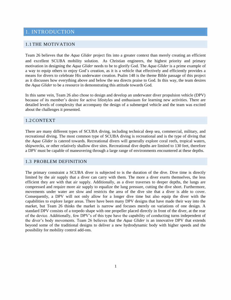
Team 26 believes that the Aqua Glider project fits into a greater context than merely creating an efficient
and excellent SCUBA mobility solution. As Christian engineers, the highest priority and primary
motivation in designing the Aqua Glider needs to be to glorify God. The Aqua Glider is a prime example of
a way to equip others to enjoy God’s creation, as it is a vehicle that effectively and efficiently provides a
means for divers to celebrate His underwater creation. Psalm 148 is the theme Bible passage of this project
as it discusses how everything above and below the sea directs praise to God. In this way, the team desires
the Aqua Glider to be a resource in demonstrating this attitude towards God. In this same vein, Team 26 also chose to design and develop an underwater diver propulsion vehicle (DPV)
because of its member’s desire for active lifestyles and enthusiasm for learning new activities. There are
detailed levels of complexity that accompany the design of a submerged vehicle and the team was excited
about the challenges it presented.
1.2 CONTEXT
There are many different types of SCUBA diving, including technical deep sea, commercial, military, and
recreational diving. The most common type of SCUBA diving is recreational and is the type of diving that
the Aqua Glider is catered towards. Recreational divers will generally explore coral reefs, tropical waters,
shipwrecks, or other relatively shallow dive sites. Recreational dive depths are limited to 130 feet, therefore
a DPV must be capable of maneuvering through a large range of environments encountered at these depths.
1.3 PROBLEM DEFINITION
The primary constraint a SCUBA diver is subjected to is the duration of the dive. Dive time is directly
limited by the air supply that a diver can carry with them. The more a diver exerts themselves, the less
efficient they are with that air supply. Additionally, as a diver traverses to deeper depths, the lungs are
compressed and require more air supply to equalize the lung pressure, cutting the dive short. Furthermore,
movements under water are slow and restricts the area of the dive site that a diver is able to cover.
Consequently, a DPV will not only allow for a longer dive time but also equip the diver with the
capabilities to explore larger areas. There have been many DPV designs that have made their way into the
market, but Team 26 thinks the market is narrow and focuses merely on variations of one design. A
standard DPV consists of a torpedo shape with one propeller placed directly in front of the diver, at the rear
of the device. Additionally, few DPV’s of this type have the capability of conducting turns independent of
the diver’s body movements. Team 26 believes that the Aqua Glider is an innovative DPV that extends
beyond some of the traditional designs to deliver a new hydrodynamic body with higher speeds and the
possibility for mobility control add-ons.
2
1.4 TEAM MEMBERS
1.4.1 ETHAN POSTMUS
Ethan Postmus is a senior Mechanical Engineering student at Calvin College. In the summer of 2015, he
interned at Monroe Products in Grand Rapids, MI. The internship developed his experience with data
analysis and process improvement for production cells. During the summer of 2016, Ethan interned at
Innotec Corporation in Zeeland, MI. There, he was able to gain valuable hands-on experience in multiple
facets of engineering, such as project management, troubleshooting, and data analysis. He used his skills in
mechanical operations along with fluid dynamics to propose solutions to the obstacles that emerged in the
development of the Aqua Glider. In his spare time, Ethan enjoys spending time with friends, playing games,
and various outdoor activities. The design of the Aqua Glider gave him a chance to combine multiple facets
of his interests into something new and exciting while participating in solving problems.
1.4.2 ZACHARY MOUW
Zachary Mouw is a senior mechanical engineering student with an international designation. During the
summer of 2016, he interned with GMB Architecture and Engineering in Holland, MI. At GMB, he
received experience in engineering consulting, specifically with respect to HVAC design. Zachary used his
project based experiences to address the implications of decisions and addressing them in team meetings.
He also used his thermal/fluid dynamics education to address the buoyancy and fluid flow of the Aqua
Glider. Outside of his academic studies, Zachary enjoys engaging in athletic and outdoor activities. The
Aqua Glider is a unique project where he was able to integrate this active lifestyle passion and intellectual
capacity to address the challenges that arose throughout the development of the Aqua Glider.
1.4.3 JAY NOYOLA
Jay Noyola is a senior mechanical engineering student with a determination to use his Calvin College
experience to help and lead. During the summer of 2015, he interned at Granger Co. in the Engineering
department and worked on data analysis and project management. He got experience with CAT Natural Gas
engines and sorted through data to optimize the running of the engines. Jay used his understanding of
project development and contributed to propelling the project forward. Jay also is a captain on the Calvin
men’s soccer team, and has gained much knowledge in leadership. He used his ability to lead and motivate
to get the best from the team and keep to moral high in crucial situations.
1.4.4 CALEB SENYSHYN
Caleb Senyshyn is a senior mechanical engineering major at Calvin College. During the summer, he
interned at Bailey Edward architecture and engineering. During his internship, he worked on mechanical
and electrical system sizing and design. In this position, he worked to find the most cost effective heating
and cooling solution to fulfill the customer’s needs while minimizing costs. This experience helped him
weigh the pros and cons of the Aqua Glider’s design decisions to find the best use of the team’s resources.
Caleb was also faced with juggling multiple different projects with shifting timetables during his internship.
His experience helped him be flexible with timetables and identify the most critical projects. Caleb helped
the team distribute manpower effectively and sort the project’s priorities when the schedule begins to shift.
3
2. PROJECT MANAGEMENT
2.1 TEAM ORGANIZATION
The development of the Aqua Glider required a level of organization in which team members were assigned
to head specified tasks. Team advisor Professor Renard Tubergen, served as the design mentor for the
group. Professor Tubergen was a resource for any questions the team had about the design project and was
ultimately the management level that the team reported to. Each team member was tasked with a managerial
task and/or with a technical task. Caleb Senyshyn managed the development of the website and the
purchasing of materials and parts for the project. On the technical side, Caleb led the controls aspect of the
project as well as overall construction. He oversaw the development and feasibility of the physical
construction of the Aqua Glider. Jay managed the lines of communication with the shop manager Phil to
address feasibility aspects of the project and develop solution ideas to problems that developed along the
way. Jay’s technical role was rooted in partnering with Caleb to learn and complete the fiberglass
fabrication process and testing for the Aqua Glider. Ethan served the team technically through managing the
welding operations and steel machining operations. Zachary was the project coordinator and oversaw the
design of the Aqua Glider and assured that the project documents were completed. Zachary’s technical role
was fulfilled as the Solidworks designer, calculation manager and headed the completion of mold CNC
milling.
2.2 PROJECT BREAKDOWN
The team divided the Aqua Glider project into five main design categories: power, buoyancy,
hydrodynamics, controls, all enveloped in the waterproofing. This presented the opportunity to allow team
members to address a specified design category. However, this did not mean that a team member(s)
completed all the requirements for that category alone. However, the individual assured and oversaw the
completion of that aspect of the project.
2.2.1 POWER
Determining the power specifications for the vehicle, required research and calculations into how the
batteries and motors could be implemented together to produce the necessary thrust and battery life. The
task considered the most effective and low risk method to power the vehicle. Caleb Senyshyn led the power
and motor application research of the project and Zach Mouw led the thrust calculations.
2.2.2 BUOYANCY
The primary goal of the buoyancy portion of the design is to attain a level of neutral buoyancy for the
vehicle. Neutral buoyancy provides the diver with a simpler operation and more efficient ride. Therefore,
evaluating how to determine the requirements and calculations to design for neutral buoyancy was a major
focus of this area of research. Additionally, methods that allow for buoyancy alteration and control was an
area of research that was also explored. Buoyancy requirements are different for fresh and saltwater
environments which added a further consideration to the design of the Aqua Glider. Zach Mouw managed
the buoyancy research and calculations.
4
2.2.3 HYDRODYNAMICS
The main focus of the hydrodynamic aspect of the project was to develop a dynamic body shape that would
reduce the drag and frictional losses the DPV will experience. The team also wanted to have an aesthetic
shape that would appeal to the customer. The challenge was to accomplish a hydrodynamic shape within the
specified dimensions and buoyancy requirements. Ethan Postmus lead the research and shape application
for the hydrodynamics of the Aqua Glider. ‘
2.2.4 CONTROLS
The team aimed to provide high levels of mobility and control in the Aqua Glider. Controls that made
direction and depth changes more effective were considerations in the research phase of the project. The
controls portion of the project also included evaluating the implementation of the controls hardware
necessary for the DPV to operate. Caleb Senyshyn headed the controls portion of the project.
2.2.5 WATERPROOFING
The overarching portion of the project that posed the most risk was the ability to successfully waterproof
the design. Any protrusions or access points for the motors, batteries, or controls had to contain the proper
sealing methods to prevent damage to the motors or shorting any circuitry. Material selection also was a
prominent factor in addressing the issue of waterproofing. Jay conducted the research into the material
selection and its fabrication.
2.3 SCHEDULE
Each semester and phase of the project began with the development of Gantt charts that can be seen in
Appendix A. The Gantt charts displayed the initial schedule expected by the team. However, as the
semester went on the team had to alter the schedule weekly to accommodate new ideas and tasks. As the
project continued to develop the team would reschedule and add tasks/deadlines using a white board at their
design station. While most of first semester involved scoping and planning the feasibility of the project, the
second semester consisted of implementation of the prototype and scheduling its fabrication. During the
design and research phases of the Aqua Glider, the team was dedicated to holding meetings on Tuesday and
Thursday nights in order to continually give updates on the project’s progress and alter the schedule as
necessary. During the fabrication and development of the prototype, the team met nearly every day to hold a
working meeting or at least touch base on any updates. The team had to spend a large portion of the design
of the Aqua Glider addressing the two biggest risks of buoyancy and waterproofing.
Before the construction of the Aqua Glider, the team scheduled time to practice different construction
techniques needed in the construction of the device. This included the fiberglass construction and sealing.
To do this, small scale models were constructed. Additional tests were conducted for the controls, motors,
and electrical system, initially set up without the frame. This allowed the team to test the motors to ensure
the controls dictated the proper behavior of the power. After all small scale testing is complete, a full scale
frame was constructed and the electrical system was implemented. Through leaving adequate time near the
project’s deadline to test the model, the team was able to address the risks of waterproofing, buoyancy, and
construction process that arose along the way.
5
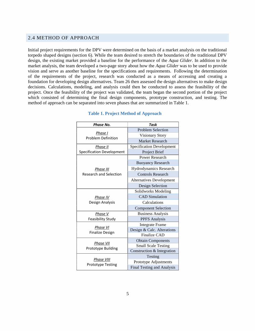
2.4 METHOD OF APPROACH
Initial project requirements for the DPV were determined on the basis of a market analysis on the traditional
torpedo shaped designs (section 6). While the team desired to stretch the boundaries of the traditional DPV
design, the existing market provided a baseline for the performance of the Aqua Glider. In addition to the
market analysis, the team developed a two-page story about how the Aqua Glider was to be used to provide
vision and serve as another baseline for the specifications and requirements. Following the determination
of the requirements of the project, research was conducted as a means of accessing and creating a
foundation for developing design alternatives. Team 26 then assessed the design alternatives to make design
decisions. Calculations, modeling, and analysis could then be conducted to assess the feasibility of the
project. Once the feasibility of the project was validated, the team began the second portion of the project
which consisted of determining the final design components, prototype construction, and testing. The
method of approach can be separated into seven phases that are summarized in Table 1.
Table 1. Project Method of Approach
Phase No. Task
Phase I Problem Definition
Problem Selection Visionary Story
Market Research Phase II
Specification Development Specification Development
Project Brief
Phase III Research and Selection
Power Research Buoyancy Research
Hydrodynamics Research
Controls Research
Alternatives Development
Design Selection
Phase IV Design Analysis
Solidworks Modeling CAD Simulation
Calculations
Component Selection Phase V
Feasibility Study Business Analysis
PPFS Analysis
Phase VI Finalize Design
Integrate Frame
Design & Calc. Alterations
Finalize CAD
Phase VII Prototype Building
Obtain Components
Small Scale Testing
Construction & Integration
Phase VIII Prototype Testing
Testing
Prototype Adjustments
Final Testing and Analysis
6
3. REQUIREMENTS & SPECIFICATIONS
3.1 OPERATION
3.1.1 SPEED
The vehicle must be able to achieve an adequate speed that will provide the diver with the ability to explore
a greater range in a single dive while delivering a sense of satisfaction purely based on the operation of the
DPV itself. After examining the market research, it was determined that a maximum speed specification of
5 mph would satisfy these conditions. This is at the high end of many of the existing DPV’s on the market
and will give the Aqua Glider an edge. A diver often desires to have speed control in their mobility
depending on the environment explored. Therefore, variable speed control is also an important aspect that
should be incorporated into a final design.
3.1.2 SIZE & WEIGHT
The Aqua Glider was also required to be easily transported above water and simple to manage underwater.
Therefore, the DPV must be designed into a manageable and compact shape while maintaining its
hydrodynamic effectiveness. It was determined that the DPV should weigh no more than 125 pounds as to
maintain the possibility of unassisted manual transportation of the device. The 125-pound specification was
a ceiling limit and the team worked to make the Aqua Glider lighter. The vehicle is required to fit within a
compact constraint, not only for flexibility in maneuverability underwater, but also to have the capability of
being transported in the trunk of a midsized vehicle.
3.1.3 BATTERY & RUN TIME
The battery life should exceed or match that of a standard dive time. Recreational dives last around one
hour, therefore, the DPV should operate without needing a recharge for a minimum of one hour. The one
hour run time is specified at maximum speed operation. Considering that the DPV will likely not be
operating at the maximum speed through the duration of the dive, the one hour run time is an adequate
specification. The turnover time for the DPV is determined by the time capabilities of the battery to
recharge. Therefore, the DPV should be designed with a maximum eight-hour recharge time in mind. This
allows for the device to be charged overnight and ready for a dive the following day. Recreational dives are
often over vacations and people will dive over a weekend or two-day period. Therefore, a further constraint
on the vehicle is that it is easily rechargeable at any place with a normal 12-volt outlet. Additionally, the
charging adapter must also be independent of the vehicle.
3.1.4 BUOYANCY
The device was designed such that attaining neutral buoyancy for optimal operation required little effort. A
non-neutrally buoyant device could result in the diver using additional energy to maintain buoyancy, the
very thing the DPV is attempting to avoid. The device must also be operable and buoyant in both salt and
fresh water, therefore the physical characteristics of each environment were taken into consideration. A
final design should allow for buoyancy alterations to ensure neutral buoyancy can be altered. A final design
of the Aqua Glider should be equipped with buoyancy capabilities of traversing depths of up to 130 feet as
this is maximum depth rating for a recreational dive.
7
3.1.5 NAVIGATIONAL CONTROL
One of the key requirements for the Aqua Glider is to equip the DPV with navigational turning controls.
The implementation of these controls will reduce the amount of body movements required to operate the
vehicle and consequently increase the efficiency of a diver’s oxygen supply. A requirement for the design
was the ability to turn through tank steering operation and alter speeds through variable speed control.
3.1.6 WATERPROOF & STRUCTURE
For the device to operate properly, it had to be entirely waterproof. No significant amount of water may
enter into the DPV during use as that would prove to be detrimental to the buoyant operation of the device
and safety of the diver. The final structural design must be robust to withstand the pressures that occur at
130 feet of depth and minor collisions. The team also made it a requirement that a waterproofed internal
access into the vehicle would be a necessary component of the design. The team wanted to ensure that the
design retained the possibility of removing the batteries from the hull of the vehicle if necessary for
replacement.
3.2 AESTHETICS
Team 26 understands that delightful harmony is a key design consideration that needs to be integrated into
the Aqua Glider. Often times, the purpose of a dive is to explore the natural beauty of the aquatic
environment and therefore, the Aqua Glider’s aesthetic integration into the environment is a significant
aspect that cannot be overlooked. The Aqua Glider should not detract or serve as a barrier to the diver’s
experience of creation. Therefore, the Aqua Glider should aesthetically blend into the natural aquatic
environment. The design was required to be derived from organic reflections of its natural environment.
The Aqua Glider should be appealing to the diver, and have more innovative features than the traditional
torpedo design. The Aqua Glider had to be a sleek and unique design, but is not unnatural. The shape is a
lot like a manta ray and the aerodynamic shape gives it a smooth riding experience. The shape is intended to
blend in with the environment and not stir commotion in the water. To ensure a low profile underwater the
Aqua Glider is also designed to operate quietly. The noise is held to below 100 decibels as to not startle and
creatures when the device is running. This is about the sound of open ocean ambient noise according to the
National Oceanic and Atmospheric Administration [1].
3.3 SAFETY
3.3.1 KEY SAFETY CONSIDERATIONS
Safety is a major component that was necessary to in the design decisions the team made. SCUBA diving is
an inherently dangerous activity with a significant need for safety precautions. Because of this, it was very
important that the team designed the Aqua Glider such that it did not increase the chance of an accident
occurring during a dive. In order to maximize the safety of the vehicle, the team developed an FMEA which
can be found in Appendix E that outlines a few of the major safety considerations.
The highest risk was in waterproofing. If the vehicle were to flood, a number of aspects could put the diver
at risk. The vehicle would lose ideal buoyancy conditions and begin to sink. As the device is connected to
8
the diver’s harness, this could potentially pull the diver down at an unknown rate. In order to mitigate these
risks, the team spent a significant amount of time researching the best possible waterproofing practices.
This involved researching into how to waterproof all the areas in the shell where controls would need to
penetrate the shell in addition to the materials that would provide the best waterproofing techniques.
A second area where safety considerations were taken into account was with the propellers. The two
propellers used to drive the device through the water are spinning extremely fast and are in close proximity
to the diver. Because of this, it is important that the team designed a duct around the propellers to keep them
from contacting with the diver. Additionally, such a consideration protects any wild life the diver may be
diving amongst.
Finally, in case the diver faced an emergency situation, a couple of quick release options should be
integrated into the final design of the Aqua Glider. The first quick release would consist of releasing any
external weights attached to the DPV. If the diver faced an emergency situation where the Aqua Glider
suddenly began to sink, a reduction in weight would cause the vehicle to rise to the surface. Similarly, if the
diver thinks that their life is in too much danger connected to the DPV, they can quickly release the harness
clip and ditch the Aqua Glider completely.
3.3.2 ADDITIONAL SAFETY CONSIDERATIONS
A safety clipping mechanism should be designed in order to keep the diver with the DPV during operation.
A clip will allow the diver to be pulled by the device rather than using arm strength to hold on.
Additionally, if the diver needed to use a hand to check gauges or make adjustments, the clip would provide
that capability. In the event that the device runs out of battery during operation, an automatic float mechanism should be
considered. Integrating this safety facet will ensure that the diver does not lose the DPV just because the
battery was drained.
In an attempt to avoid injury while transporting the device to and from water, handles will be installed in
strategic locations. Ideally, one person will be able to move it, however, in the case that it is a two-person
job, the handles will provide the necessary control.
3.3.3 RISK ASSESSMENT
An FMEA was conducted in Appendix E to determine the greatest risks to the project and safety of the
diver. After analyzing the results of the FMEA, the greatest risks to the safety of the diver and the
performance of the vehicle are buoyancy and waterproofing. These were the two overarching factors that
drove the design decisions and necessary alterations of the Aqua Glider.
9
4. DESIGN ALTERNATIVES AND SELECTION
4.1 POWER
4.1.1 DESIGN RESEARCH (BATTERY)
The first aspect of the batteries the team researched was their chemical composition. The first type of
battery that was considered was lead-acid batteries. These batteries are extremely common, and therefore,
cost effective. Lead-acid batteries come in a variety of sizes so finding a battery to meet the Aqua Glider’s
application was not difficult. The downsides of these types of batteries is their weight and energy density.
Lead-acid batteries are notoriously heavy and large. In addition to this, these types of batteries are not as
resilient to repeated full drain and recharge. Nickel Metal Hydride (NiMH) were another promising battery option for the team. NiMH batteries are
generally very long lasting batteries that will not lose significant performance after recharging multiple
times However, they will tend to lose performance if they are required to sit for long periods of time
without use. NiMH batteries are also much more expensive than lead-acid batteries and are far less
common. They are also most commonly used in very small scale applications, like model airplanes and RC
cars. Due to this, finding a NiMH battery large enough to fit the team’s application will be difficult.
The last type of battery that was considered was Lithium batteries. Lithium batteries offer the best life and
react relatively well to being left for long periods of time. Lithium batteries are also very light, and
therefore have a high energy density. The downside to lithium batteries is their cost and availability. They
also tend to be used in small applications like NiMH batteries, so finding a large enough battery could be
difficult. Lithium batteries also tend to be used in specialty cases and therefore can be cost prohibitive to the
team’s generalized application. [2] [3] [4]
4.1.2 DESIGN CONSIDERATIONS & ALT.
After researching a few examples of each type of battery, it was clear that the Lithium and NiMH batteries
were not feasible for the project. As can be seen in Table 2, the Dakota Lithium ion battery offers only 10
Amp hours (Ah) of capacity with a $25 price tag. Similarly, the Tenergy battery offered 2 Ah for $25. This
is due to the fact that NiMH batteries provide power in very small packages but do not meet the energy
capacity necessary for the Aqua Glider. In all, these battery types simply were not feasible for this
application. Their price points were much too high and did not provide the necessary power for the device
to meet the design specifications.
4.1.3 DESIGN DECISIONS
This led the team to ultimately decide that lead acid batteries would provide the necessary energy density
and discharge rate for the motors while fitting nicely into the budget. There is a large market for lead acid
batteries but certain specifications had to be met by the batteries so they could work with the team’s chosen
motor type.
First, the battery the team chose would need to be a sealed lead acid (SLA) battery. This ensures that none
of the internal chemicals of the battery would spill out into the interior of the Aqua Glider. In addition to not
10
spilling, the SLA type batteries allow the team to orient the battery in whatever way works best. All the lead
acid batteries the team looked at were of the SLA type because this is a necessary characteristic for the
battery. All of the lead acid batteries under consideration by the team also meet the necessary maximum
discharge rate of 42 Amps as dictated by the motor manufacturer.
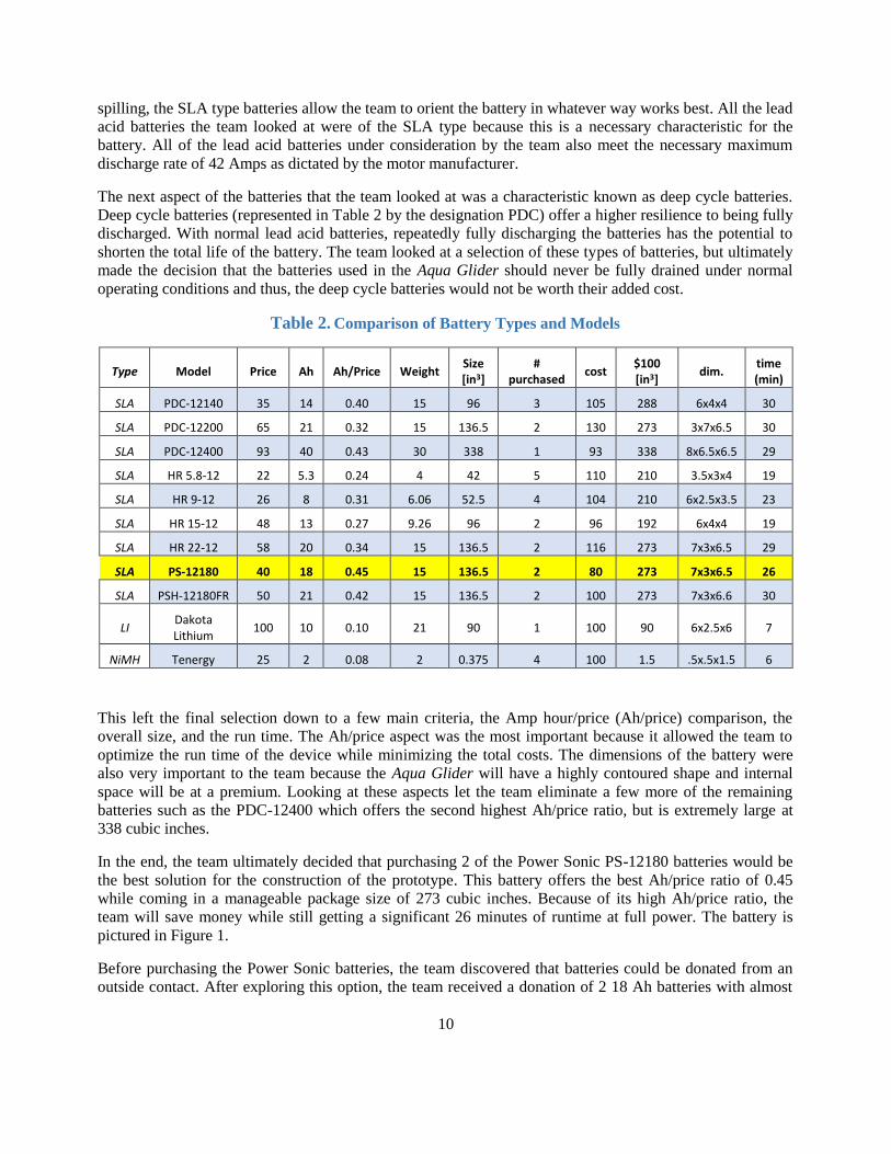
The next aspect of the batteries that the team looked at was a characteristic known as deep cycle batteries.
Deep cycle batteries (represented in Table 2 by the designation PDC) offer a higher resilience to being fully
discharged. With normal lead acid batteries, repeatedly fully discharging the batteries has the potential to
shorten the total life of the battery. The team looked at a selection of these types of batteries, but ultimately
made the decision that the batteries used in the Aqua Glider should never be fully drained under normal
operating conditions and thus, the deep cycle batteries would not be worth their added cost.
Table 2. Comparison of Battery Types and Models
Type Model Price Ah Ah/Price Weight Size [in3]
# purchased
cost $100 [in3]
dim. time (min)
SLA PDC-12140 35 14 0.40 15 96 3 105 288 6x4x4 30
SLA PDC-12200 65 21 0.32 15 136.5 2 130 273 3x7x6.5 30
SLA PDC-12400 93 40 0.43 30 338 1 93 338 8x6.5x6.5 29
SLA HR 5.8-12 22 5.3 0.24 4 42 5 110 210 3.5x3x4 19
SLA HR 9-12 26 8 0.31 6.06 52.5 4 104 210 6x2.5x3.5 23
SLA HR 15-12 48 13 0.27 9.26 96 2 96 192 6x4x4 19
SLA HR 22-12 58 20 0.34 15 136.5 2 116 273 7x3x6.5 29
SLA PS-12180 40 18 0.45 15 136.5 2 80 273 7x3x6.5 26
SLA PSH-12180FR 50 21 0.42 15 136.5 2 100 273 7x3x6.6 30
LI Dakota Lithium
100 10 0.10 21 90 1 100 90 6x2.5x6 7
NiMH Tenergy 25 2 0.08 2 0.375 4 100 1.5 .5x.5x1.5 6
This left the final selection down to a few main criteria, the Amp hour/price (Ah/price) comparison, the
overall size, and the run time. The Ah/price aspect was the most important because it allowed the team to
optimize the run time of the device while minimizing the total costs. The dimensions of the battery were
also very important to the team because the Aqua Glider will have a highly contoured shape and internal
space will be at a premium. Looking at these aspects let the team eliminate a few more of the remaining
batteries such as the PDC-12400 which offers the second highest Ah/price ratio, but is extremely large at
338 cubic inches.
In the end, the team ultimately decided that purchasing 2 of the Power Sonic PS-12180 batteries would be
the best solution for the construction of the prototype. This battery offers the best Ah/price ratio of 0.45
while coming in a manageable package size of 273 cubic inches. Because of its high Ah/price ratio, the
team will save money while still getting a significant 26 minutes of runtime at full power. The battery is
pictured in Figure 1.
Before purchasing the Power Sonic batteries, the team discovered that batteries could be donated from an
outside contact. After exploring this option, the team received a donation of 2 18 Ah batteries with almost
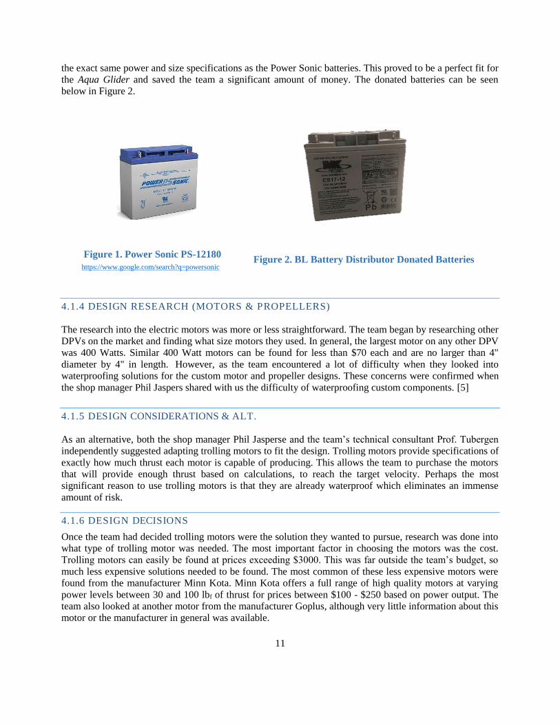
11
the exact same power and size specifications as the Power Sonic batteries. This proved to be a perfect fit for
the Aqua Glider and saved the team a significant amount of money. The donated batteries can be seen
below in Figure 2.
https://www.google.com/search?q=powersonic
4.1.4 DESIGN RESEARCH (MOTORS & PROPELLERS)
The research into the electric motors was more or less straightforward. The team began by researching other
DPVs on the market and finding what size motors they used. In general, the largest motor on any other DPV
was 400 Watts. Similar 400 Watt motors can be found for less than $70 each and are no larger than 4"
diameter by 4" in length. However, as the team encountered a lot of difficulty when they looked into
waterproofing solutions for the custom motor and propeller designs. These concerns were confirmed when
the shop manager Phil Jaspers shared with us the difficulty of waterproofing custom components. [5]
4.1.5 DESIGN CONSIDERATIONS & ALT.
As an alternative, both the shop manager Phil Jasperse and the team’s technical consultant Prof. Tubergen
independently suggested adapting trolling motors to fit the design. Trolling motors provide specifications of
exactly how much thrust each motor is capable of producing. This allows the team to purchase the motors
that will provide enough thrust based on calculations, to reach the target velocity. Perhaps the most
significant reason to use trolling motors is that they are already waterproof which eliminates an immense
amount of risk.
4.1.6 DESIGN DECISIONS
Once the team had decided trolling motors were the solution they wanted to pursue, research was done into
what type of trolling motor was needed. The most important factor in choosing the motors was the cost.
Trolling motors can easily be found at prices exceeding $3000. This was far outside the team’s budget, so
much less expensive solutions needed to be found. The most common of these less expensive motors were
found from the manufacturer Minn Kota. Minn Kota offers a full range of high quality motors at varying
power levels between 30 and 100 lbf of thrust for prices between $100 - $250 based on power output. The
team also looked at another motor from the manufacturer Goplus, although very little information about this
motor or the manufacturer in general was available.
Figure 2. BL Battery Distributor Donated Batteries Figure 1. Power Sonic PS-12180
12
From these two manufacturers, three motors were chosen that fit within the budget. In order to decide
between these 3, a decision matrix was made and can be seen as Table 3.
Table 3. Trolling Motor Decision Matrix
Cost
Ease of Implementation
Information Build Quality Power
Consumption Power Total
Weight 9 3 6 3 7 9 --
Minn 30 7 8 9 8 8 4 --
63 24 54 24 56 36 257
Minn 40 5 8 9 8 7 7 --
45 24 54 24 49 63 259
Goplus 86 5 6 4 5 5 10 --
45 18 24 15 35 90 227
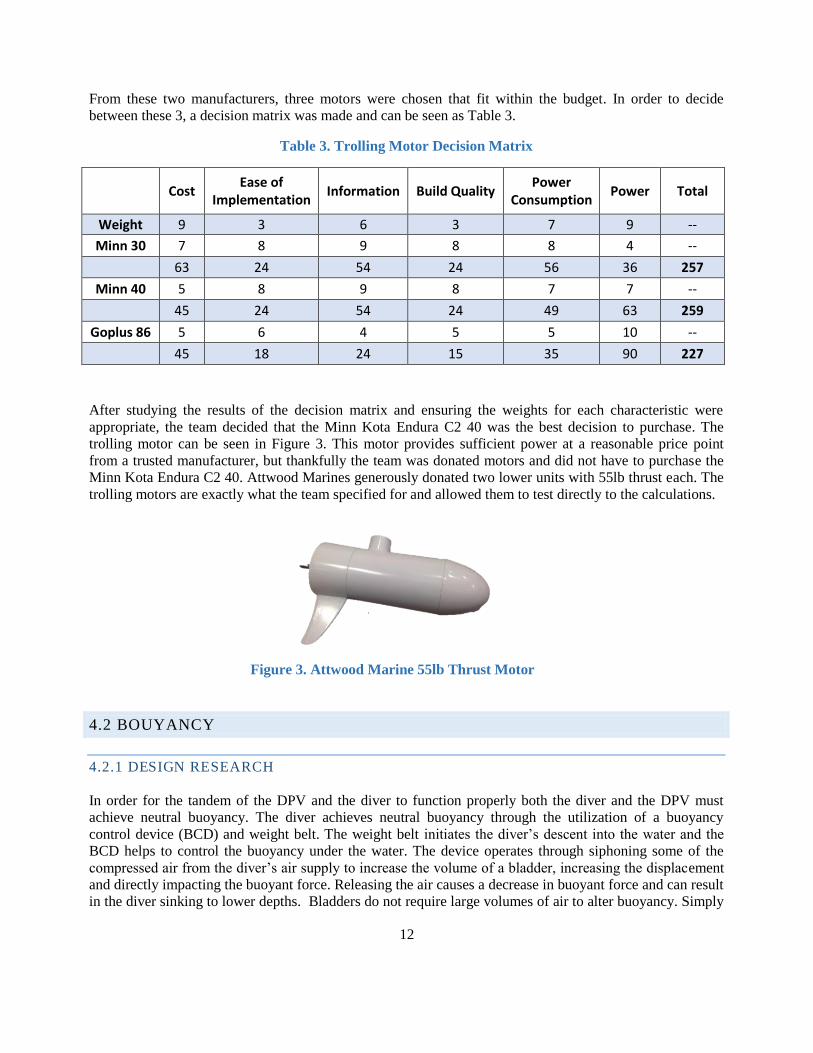
After studying the results of the decision matrix and ensuring the weights for each characteristic were
appropriate, the team decided that the Minn Kota Endura C2 40 was the best decision to purchase. The
trolling motor can be seen in Figure 3. This motor provides sufficient power at a reasonable price point
from a trusted manufacturer, but thankfully the team was donated motors and did not have to purchase the
Minn Kota Endura C2 40. Attwood Marines generously donated two lower units with 55lb thrust each. The
trolling motors are exactly what the team specified for and allowed them to test directly to the calculations.
4.2 BOUYANCY
4.2.1 DESIGN RESEARCH
In order for the tandem of the DPV and the diver to function properly both the diver and the DPV must
achieve neutral buoyancy. The diver achieves neutral buoyancy through the utilization of a buoyancy
control device (BCD) and weight belt. The weight belt initiates the diver’s descent into the water and the
BCD helps to control the buoyancy under the water. The device operates through siphoning some of the
compressed air from the diver’s air supply to increase the volume of a bladder, increasing the displacement
and directly impacting the buoyant force. Releasing the air causes a decrease in buoyant force and can result
in the diver sinking to lower depths. Bladders do not require large volumes of air to alter buoyancy. Simply
Figure 3. Attwood Marine 55lb Thrust Motor
13
breathing and filling the volume of the diver’s lungs is enough to affect their buoyancy. Therefore, the
slightest alterations in the volume to weight ratio can have significant effects on buoyancy. Neutral buoyancy is achieved for a DPV when the density of water is equal to the average density of the
DPV. Additionally, Archimedes principle plays an important role in the determination of the buoyant force
that acts on an object. Archimedes principle states that the buoyant force acting on an object is equal to the
weight of water that is displaced by that particular object. Therefore, the weight of the device must equal
the buoyant force to achieve neutral buoyancy. Using these two principles, there are ways to accommodate
for, and ensure that the Aqua Glider achieves neutral buoyancy. However, it is often better for underwater
vehicles to remain slightly positively buoyant in the event that the device fails. Additionally, it is always
easier to add weight than it is to take weight away. “As a general rule for small vehicles, the buoyant force
should be designed as 4% more than the weight of the vehicle. Weights are then added to bring the buoyant
force to within 1 – 2% of the submerged weight” [6]. The center of buoyancy is also an important
consideration. The center of buoyancy is equal to the center of gravity of the displaced liquid.
4.2.2 DESIGN CONSIDERATIONS & ALT.
Trim Weights
One option to compensate for buoyancy is to design the vehicle positively buoyant and then add the
necessary weight to achieve neutral buoyancy. Having adjustable weight attachments will allow for the
accommodation of different aquatic environments that have different density characteristics. Trim weights
are generally disposable by many divers and can be released to quickly resurface. However, while it is a
low risk and relatively simple solution it doesn’t allow for mid-dive buoyancy alterations.
Ballast Design
A second option that is used on many submarines involves the use of a ballast tank. This would help the
DPV achieve neutral buoyancy and then more water can be added to establish a negative buoyant force.
Resurfacing and positive buoyancy are accomplished through the use of compressed air to expel water out
of the tank, lowering the vehicle’s weight and consequently, the vehicle’s average density. Although, on
large submarines compressed air is contained on board, one consideration for the Aqua Glider is to use a
mechanical system to expel water out of the tank. Additional mechanical systems that could be used on
smaller underwater devices include a mechanical extension and retraction of a piston rod. This piston rod
could be used to either be manually operated by the diver himself or through a gear and actuator. Ballast
tanks are a useful for mid-dive adjustments.
4.2.3 DESIGN DECISIONS
Team 26 will first plan to implement the method of adding trim weights to the vehicle to achieve neutral
buoyancy. This method provides the simplest solution to the problem and is an established practice already
used by divers. In the event that there is extra time at the end of the project, the team will use two air
cylinders that are operated through a small motor actuator and set of worm gears to operate a ballast tank.
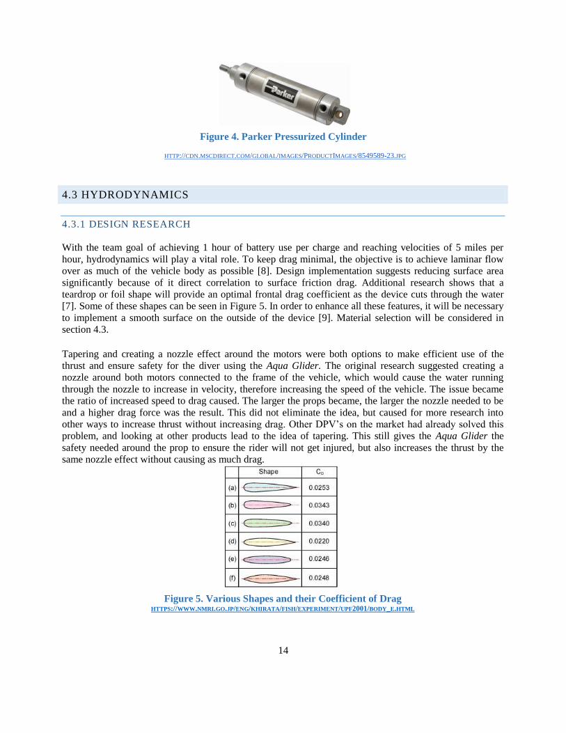
The cylinders the team plans to use are found in Figure 4. This will allow the diver to make on board fine
tune adjustments at shallow depths before descending. To eliminate the number of moving components and
the need to waterproof, the team selected to use a motor and worm gear for their ease of operation and
reliability.
14
Figure 4. Parker Pressurized Cylinder
HTTP://CDN.MSCDIRECT.COM/GLOBAL/IMAGES/PRODUCTIMAGES/8549589-23.JPG
4.3 HYDRODYNAMICS
4.3.1 DESIGN RESEARCH
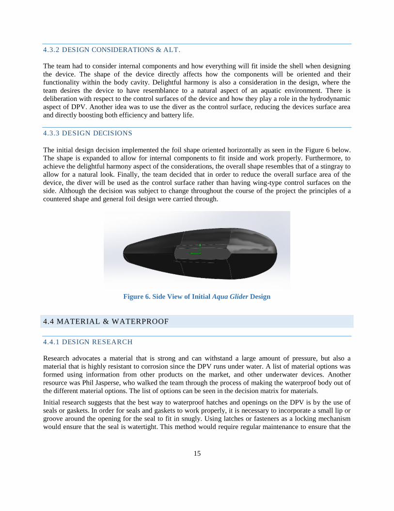
With the team goal of achieving 1 hour of battery use per charge and reaching velocities of 5 miles per
hour, hydrodynamics will play a vital role. To keep drag minimal, the objective is to achieve laminar flow
over as much of the vehicle body as possible [8]. Design implementation suggests reducing surface area
significantly because of it direct correlation to surface friction drag. Additional research shows that a
teardrop or foil shape will provide an optimal frontal drag coefficient as the device cuts through the water
[7]. Some of these shapes can be seen in Figure 5. In order to enhance all these features, it will be necessary
to implement a smooth surface on the outside of the device [9]. Material selection will be considered in
section 4.3. Tapering and creating a nozzle effect around the motors were both options to make efficient use of the
thrust and ensure safety for the diver using the Aqua Glider. The original research suggested creating a
nozzle around both motors connected to the frame of the vehicle, which would cause the water running
through the nozzle to increase in velocity, therefore increasing the speed of the vehicle. The issue became
the ratio of increased speed to drag caused. The larger the props became, the larger the nozzle needed to be
and a higher drag force was the result. This did not eliminate the idea, but caused for more research into
other ways to increase thrust without increasing drag. Other DPV’s on the market had already solved this
problem, and looking at other products lead to the idea of tapering. This still gives the Aqua Glider the
safety needed around the prop to ensure the rider will not get injured, but also increases the thrust by the
same nozzle effect without causing as much drag.
Figure 5. Various Shapes and their Coefficient of Drag HTTPS://WWW.NMRI.GO.JP/ENG/KHIRATA/FISH/EXPERIMENT/UPF2001/BODY_E.HTML
15
4.3.2 DESIGN CONSIDERATIONS & ALT.
The team had to consider internal components and how everything will fit inside the shell when designing
the device. The shape of the device directly affects how the components will be oriented and their
functionality within the body cavity. Delightful harmony is also a consideration in the design, where the
team desires the device to have resemblance to a natural aspect of an aquatic environment. There is
deliberation with respect to the control surfaces of the device and how they play a role in the hydrodynamic
aspect of DPV. Another idea was to use the diver as the control surface, reducing the devices surface area
and directly boosting both efficiency and battery life.
4.3.3 DESIGN DECISIONS
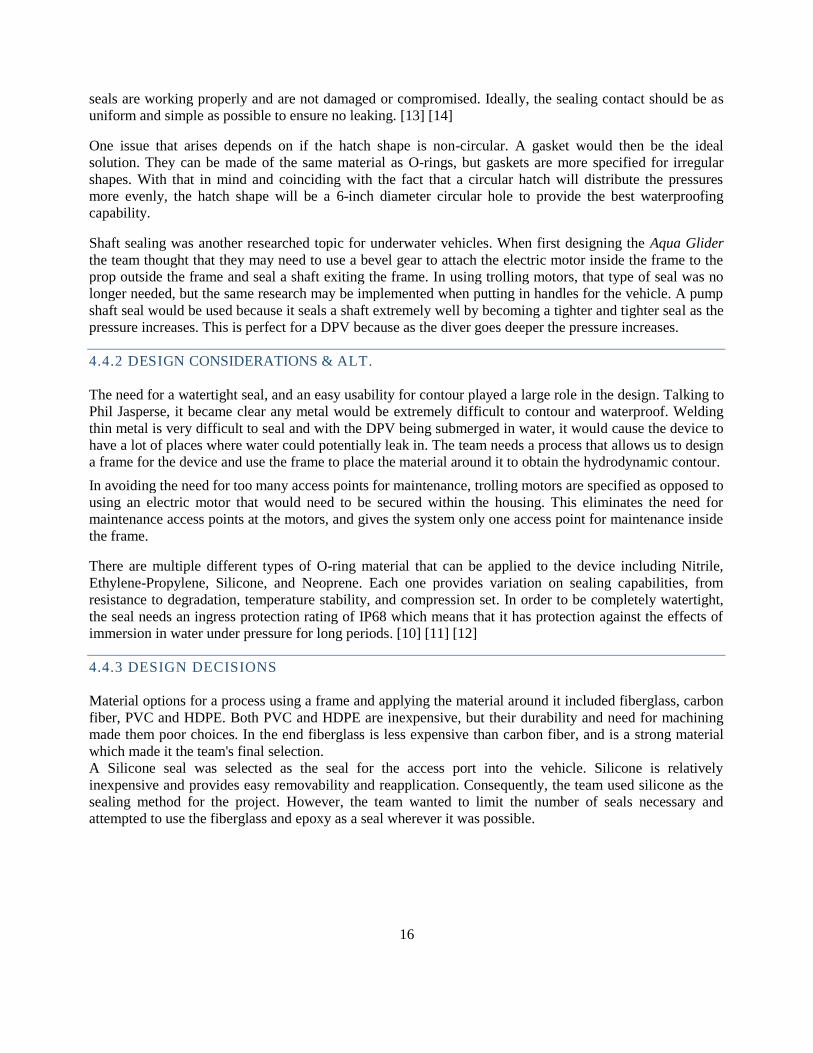
The initial design decision implemented the foil shape oriented horizontally as seen in the Figure 6 below.
The shape is expanded to allow for internal components to fit inside and work properly. Furthermore, to
achieve the delightful harmony aspect of the considerations, the overall shape resembles that of a stingray to
allow for a natural look. Finally, the team decided that in order to reduce the overall surface area of the
device, the diver will be used as the control surface rather than having wing-type control surfaces on the
side. Although the decision was subject to change throughout the course of the project the principles of a
countered shape and general foil design were carried through.
Figure 6. Side View of Initial Aqua Glider Design
4.4 MATERIAL & WATERPROOF
4.4.1 DESIGN RESEARCH
Research advocates a material that is strong and can withstand a large amount of pressure, but also a
material that is highly resistant to corrosion since the DPV runs under water. A list of material options was
formed using information from other products on the market, and other underwater devices. Another
resource was Phil Jasperse, who walked the team through the process of making the waterproof body out of
the different material options. The list of options can be seen in the decision matrix for materials.
Initial research suggests that the best way to waterproof hatches and openings on the DPV is by the use of
seals or gaskets. In order for seals and gaskets to work properly, it is necessary to incorporate a small lip or
groove around the opening for the seal to fit in snugly. Using latches or fasteners as a locking mechanism
would ensure that the seal is watertight. This method would require regular maintenance to ensure that the
16
seals are working properly and are not damaged or compromised. Ideally, the sealing contact should be as
uniform and simple as possible to ensure no leaking. [13] [14]
One issue that arises depends on if the hatch shape is non-circular. A gasket would then be the ideal
solution. They can be made of the same material as O-rings, but gaskets are more specified for irregular
shapes. With that in mind and coinciding with the fact that a circular hatch will distribute the pressures
more evenly, the hatch shape will be a 6-inch diameter circular hole to provide the best waterproofing
capability.
Shaft sealing was another researched topic for underwater vehicles. When first designing the Aqua Glider
the team thought that they may need to use a bevel gear to attach the electric motor inside the frame to the
prop outside the frame and seal a shaft exiting the frame. In using trolling motors, that type of seal was no
longer needed, but the same research may be implemented when putting in handles for the vehicle. A pump
shaft seal would be used because it seals a shaft extremely well by becoming a tighter and tighter seal as the
pressure increases. This is perfect for a DPV because as the diver goes deeper the pressure increases.
4.4.2 DESIGN CONSIDERATIONS & ALT.
The need for a watertight seal, and an easy usability for contour played a large role in the design. Talking to
Phil Jasperse, it became clear any metal would be extremely difficult to contour and waterproof. Welding
thin metal is very difficult to seal and with the DPV being submerged in water, it would cause the device to
have a lot of places where water could potentially leak in. The team needs a process that allows us to design
a frame for the device and use the frame to place the material around it to obtain the hydrodynamic contour.
In avoiding the need for too many access points for maintenance, trolling motors are specified as opposed to
using an electric motor that would need to be secured within the housing. This eliminates the need for
maintenance access points at the motors, and gives the system only one access point for maintenance inside
the frame.
There are multiple different types of O-ring material that can be applied to the device including Nitrile,
Ethylene-Propylene, Silicone, and Neoprene. Each one provides variation on sealing capabilities, from
resistance to degradation, temperature stability, and compression set. In order to be completely watertight,
the seal needs an ingress protection rating of IP68 which means that it has protection against the effects of
immersion in water under pressure for long periods. [10] [11] [12]
4.4.3 DESIGN DECISIONS
Material options for a process using a frame and applying the material around it included fiberglass, carbon
fiber, PVC and HDPE. Both PVC and HDPE are inexpensive, but their durability and need for machining
made them poor choices. In the end fiberglass is less expensive than carbon fiber, and is a strong material
which made it the team's final selection. A Silicone seal was selected as the seal for the access port into the vehicle. Silicone is relatively
inexpensive and provides easy removability and reapplication. Consequently, the team used silicone as the
sealing method for the project. However, the team wanted to limit the number of seals necessary and
attempted to use the fiberglass and epoxy as a seal wherever it was possible.
17
4.5 CONTROLS
4.5.1 DESIGN RESEARCH
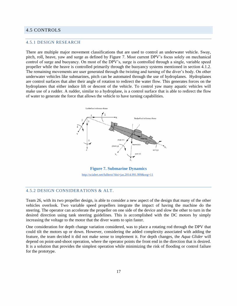
There are multiple major movement classifications that are used to control an underwater vehicle. Sway,
pitch, roll, heave, yaw and surge as defined by Figure 7. Most current DPV’s focus solely on mechanical
control of surge and buoyancy. On most of the DPV’s, surge is controlled through a single, variable speed
propeller while the heave is controlled primarily through the buoyancy systems mentioned in section 4.1.2.
The remaining movements are user generated through the twisting and turning of the diver’s body. On other
underwater vehicles like submarines, pitch can be automated through the use of hydroplanes. Hydroplanes
are control surfaces that alter their angle of rotation to redirect the water flow. This generates forces on the
hydroplanes that either induce lift or descent of the vehicle. To control yaw many aquatic vehicles will
make use of a rudder. A rudder, similar to a hydroplane, is a control surface that is able to redirect the flow
of water to generate the force that allows the vehicle to have turning capabilities.
Figure 7. Submarine Dynamics
http://scialert.net/fulltext/?doi=jas.2014.991.999&org=11
4.5.2 DESIGN CONSIDERATIONS & ALT.
Team 26, with its two propeller design, is able to consider a new aspect of the design that many of the other
vehicles overlook. Two variable speed propellers integrate the impact of having the machine do the
steering. The operator can accelerate the propeller on one side of the device and slow the other to turn in the
desired direction using tank steering guidelines. This is accomplished with the DC motors by simply
increasing the voltage to the motor that the diver wants to spin faster.
One consideration for depth change variation considered, was to place a rotating rod through the DPV that
could tilt the motors up or down. However, considering the added complexity associated with adding the
feature, the team decided it did not make sense to implement it. For depth changes, the Aqua Glider will
depend on point-and-shoot operation, where the operator points the front end in the direction that is desired.
It is a solution that provides the simplest operation while minimizing the risk of flooding or control failure
for the prototype.
18
4.5.3 DESIGN DECISIONS
The two-handed on/off switch control handle design will be used for testing purposes, but further in
development, a control system will be optimized so that the diver may operate the DPV with only one hand
with variable speeds. This would allow the diver to have a free hand to deal with respirators, tubes, or
gauges that the diver needs to be aware of throughout their excursion.
19
5. PRODUCT DESIGN IMPLEMENTATION
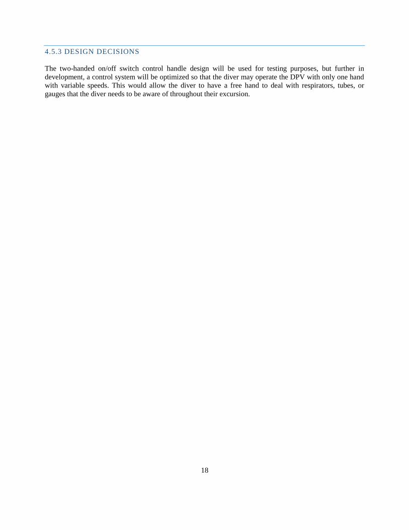
5.1 SCOPE DEFINITION & SYSTEM DESIGN
The main system for Aqua Glider consists primarily of 12 V batteries that drive the trolling motors located
at the wings of the DPV. Figure 8 shows an extended system architecture that would include actuators that
are also powered by the batteries to drive the functions of the ballast tanks. Additionally, variable speed
controllers would be wired to trolling motors and batteries to provide the diver with further maneuverability
options. There would be one central battery hub in the extended design to provide a degree of redundancy in
the operation of the vehicle. If one battery were to fail, there would still be an operable battery but at a
reduced life. However, as the team progressed in the development of the project they redefined the scope.
The ballast tank and variable speed control were set aside and a simplified proof of concept model that
consisted of two independent battery and motor systems operated by an on/off switch was implemented as
shown in Figure 9. The controls scope reduction was a crucial design decision in allowing the team to prove
the design’s concept.
Figure 8. Extended System Architecture Figure 9. Proof of Concept System Architecture
5.2 HYDRODYAMICS & SHAPE
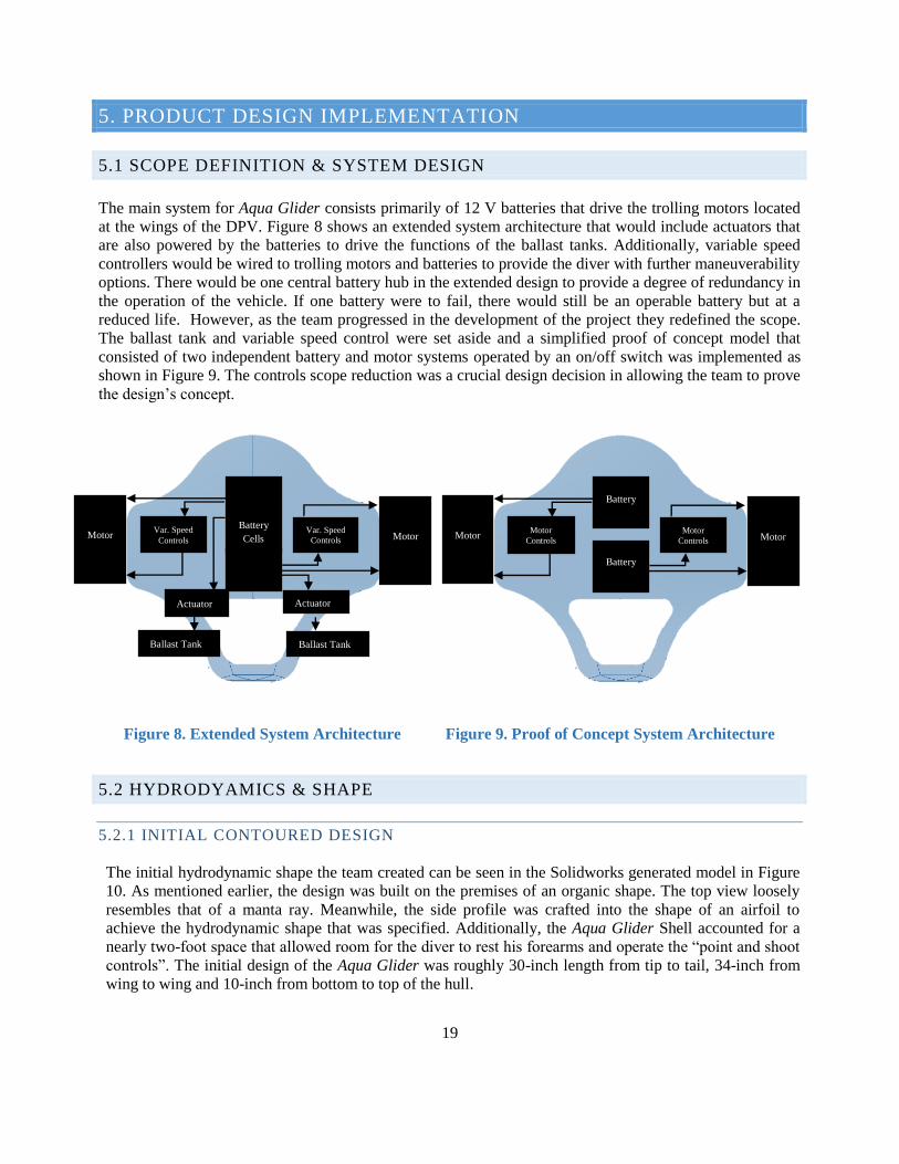
5.2.1 INITIAL CONTOURED DESIGN
The initial hydrodynamic shape the team created can be seen in the Solidworks generated model in Figure
10. As mentioned earlier, the design was built on the premises of an organic shape. The top view loosely
resembles that of a manta ray. Meanwhile, the side profile was crafted into the shape of an airfoil to
achieve the hydrodynamic shape that was specified. Additionally, the Aqua Glider Shell accounted for a
nearly two-foot space that allowed room for the diver to rest his forearms and operate the “point and shoot
controls”. The initial design of the Aqua Glider was roughly 30-inch length from tip to tail, 34-inch from
wing to wing and 10-inch from bottom to top of the hull.
Battery
Cells
Motor Motor Var. Speed
Controls
Var. Speed
Controls
Ballast Tank Ballast Tank
Actuator Actuator
Battery
Battery
Motor Motor Motor
Controls
Motor
Controls
20
Figure 10. Initial CAD Model of the Aqua Glider
5.2.2 ALTERED CONTOURED DESIGN
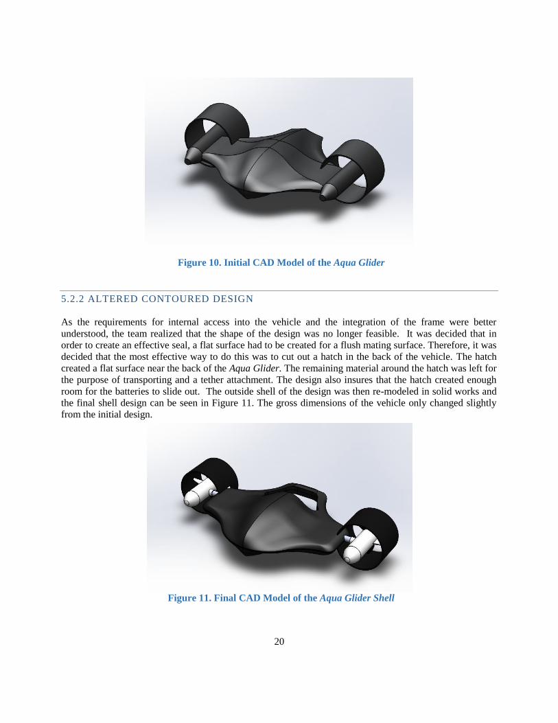
As the requirements for internal access into the vehicle and the integration of the frame were better
understood, the team realized that the shape of the design was no longer feasible. It was decided that in
order to create an effective seal, a flat surface had to be created for a flush mating surface. Therefore, it was
decided that the most effective way to do this was to cut out a hatch in the back of the vehicle. The hatch
created a flat surface near the back of the Aqua Glider. The remaining material around the hatch was left for
the purpose of transporting and a tether attachment. The design also insures that the hatch created enough
room for the batteries to slide out. The outside shell of the design was then re-modeled in solid works and
the final shell design can be seen in Figure 11. The gross dimensions of the vehicle only changed slightly
from the initial design.
Figure 11. Final CAD Model of the Aqua Glider Shell
21
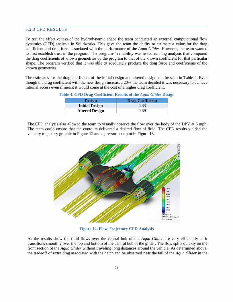
5.2.3 CFD RESULTS
To test the effectiveness of the hydrodynamic shape the team conducted an external computational flow
dynamics (CFD) analysis in Solidworks. This gave the team the ability to estimate a value for the drag
coefficient and drag force associated with the performance of the Aqua Glider. However, the team wanted
to first establish trust in the program. The programs’ reliability was tested running analysis that compared
the drag coefficients of known geometries by the program to that of the known coefficient for that particular
shape. The program verified that it was able to adequately produce the drag force and coefficients of the
known geometries.
The estimates for the drag coefficient of the initial design and altered design can be seen in Table 4. Even
though the drag coefficient with the new design increased 20% the team decided it was necessary to achieve
internal access even if meant it would come at the cost of a higher drag coefficient.
Table 4. CFD Drag Coefficient Results of the Aqua Glider Design
The CFD analysis also allowed the team to visually observe the flow over the body of the DPV at 5 mph.
The team could ensure that the contours delivered a desired flow of fluid. The CFD results yielded the
velocity trajectory graphic in Figure 12 and a pressure cut plot in Figure 13.
As the results show the fluid flows over the central hub of the Aqua Glider are very efficiently as it
transitions smoothly over the top and bottom of the central hub of the glider. The flow splits quickly on the
front section of the Aqua Glider without traveling long distances around the vehicle. As determined above,
the tradeoff of extra drag associated with the hatch can be observed near the tail of the Aqua Glider in the
Design Drag Coefficient
Initial Design 0.33
Altered Design 0.39
Figure 12. Flow Trajectory CFD Analysis
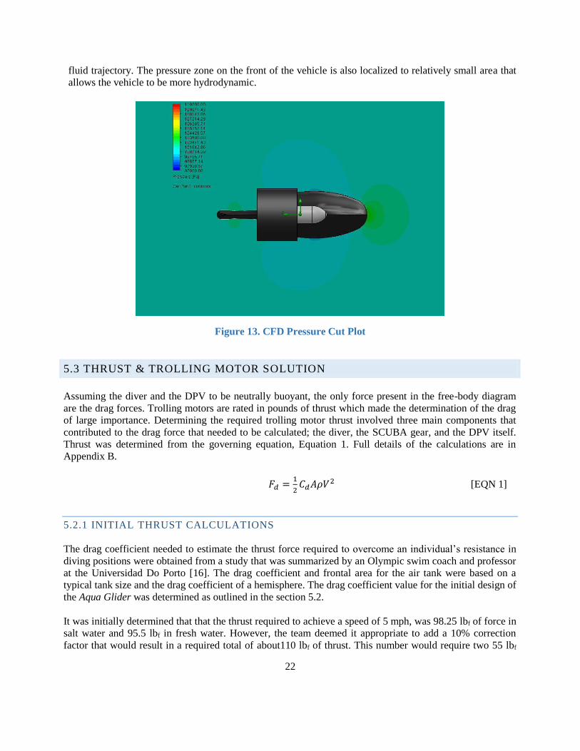
22
Figure 13. CFD Pressure Cut Plot
fluid trajectory. The pressure zone on the front of the vehicle is also localized to relatively small area that
allows the vehicle to be more hydrodynamic.
5.3 THRUST & TROLLING MOTOR SOLUTION
Assuming the diver and the DPV to be neutrally buoyant, the only force present in the free-body diagram
are the drag forces. Trolling motors are rated in pounds of thrust which made the determination of the drag
of large importance. Determining the required trolling motor thrust involved three main components that
contributed to the drag force that needed to be calculated; the diver, the SCUBA gear, and the DPV itself.
Thrust was determined from the governing equation, Equation 1. Full details of the calculations are in
Appendix B.
𝐹𝑑 =1
2𝐶𝑑𝐴𝜌𝑉2 [EQN 1]
5.2.1 INITIAL THRUST CALCULATIONS
The drag coefficient needed to estimate the thrust force required to overcome an individual’s resistance in
diving positions were obtained from a study that was summarized by an Olympic swim coach and professor
at the Universidad Do Porto [16]. The drag coefficient and frontal area for the air tank were based on a
typical tank size and the drag coefficient of a hemisphere. The drag coefficient value for the initial design of
the Aqua Glider was determined as outlined in the section 5.2. It was initially determined that that the thrust required to achieve a speed of 5 mph, was 98.25 lbf of force in
salt water and 95.5 lbf in fresh water. However, the team deemed it appropriate to add a 10% correction
factor that would result in a required total of about110 lbf of thrust. This number would require two 55 lbf
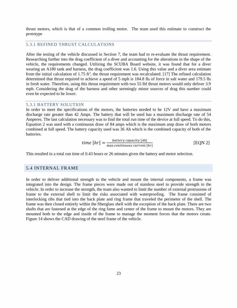
23
thrust motors, which is that of a common trolling motor. The team used this estimate to construct the
prototype
5.3.1 REFINED THRUST CALCULATIONS
After the testing of the vehicle discussed in Section 7, the team had to re-evaluate the thrust requirement.
Researching further into the drag coefficient of a diver and accounting for the alterations in the shape of the
vehicle, the requirements changed. Utilizing the SCUBA Board website, it was found that for a diver
wearing an A180 tank and harness, the drag coefficient was 1.6. Using this value and a diver area estimate
from the initial calculation of 1.75 ft3, the thrust requirement was recalculated. [17] The refined calculation
determined that thrust required to achieve a speed of 5 mph is 184.8 lbf of force in salt water and 179.5 lbf
in fresh water. Therefore, using this thrust requirement with two 55 lbf thrust motors would only deliver 3.9
mph. Considering the drag of the harness and other seemingly minor sources of drag this number could
even be expected to be lower.
5.3.1 BATTERY SOLUTION
In order to meet the specifications of the motors, the batteries needed to be 12V and have a maximum
discharge rate greater than 42 Amps. The battery that will be used has a maximum discharge rate of 54
Amperes. The last calculation necessary was to find the total run time of the device at full speed. To do this,
Equation 2 was used with a continuous draw of 84 amps which is the maximum amp draw of both motors
combined at full speed. The battery capacity used was 36 Ah which is the combined capacity of both of the
batteries.
𝑡𝑖𝑚𝑒 [ℎ𝑟] =𝑏𝑎𝑡𝑡𝑒𝑟𝑦 𝑐𝑎𝑝𝑎𝑐𝑖𝑡𝑦 [𝐴ℎ]
max 𝑐𝑜𝑛𝑡𝑖𝑛𝑢𝑜𝑢𝑠 𝑐𝑢𝑟𝑟𝑒𝑛𝑡 [ℎ𝑟] [EQN 2]
This resulted in a total run time of 0.43 hours or 26 minutes given the battery and motor selection.
5.4 INTERNAL FRAME
In order to deliver additional strength to the vehicle and mount the internal components, a frame was
integrated into the design. The frame pieces were made out of stainless steel to provide strength to the
vehicle. In order to increase the strength, the team also wanted to limit the number of external protrusions of
frame to the external shell to limit the risks associated with waterproofing. The frame consisted of
interlocking ribs that tied into the back plate and ring frame that traveled the perimeter of the shell. The
frame was then closed entirely within the fiberglass shell with the exception of the back plate. There are two
shafts that are fastened at the edge of the ring fame and center of the frame to mount the motors. They are
mounted both to the edge and inside of the frame to manage the moment forces that the motors create.
Figure 14 shows the CAD drawing of the steel frame of the vehicle.
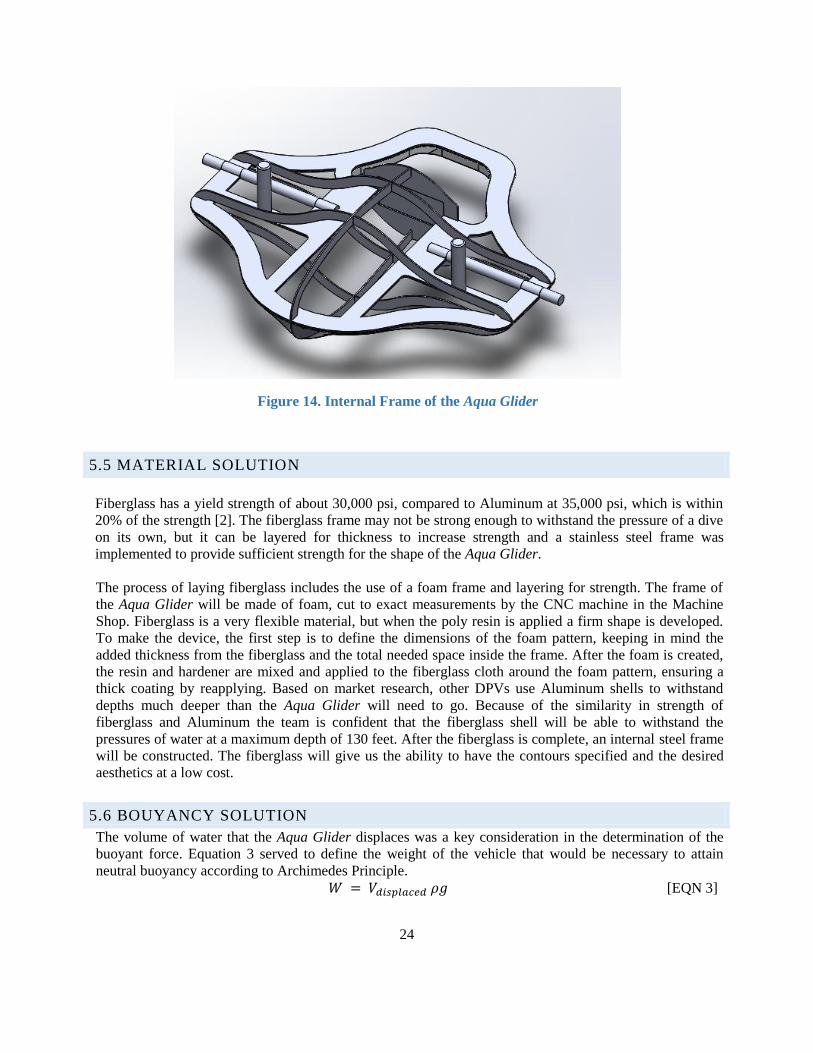
24
5.5 MATERIAL SOLUTION
Fiberglass has a yield strength of about 30,000 psi, compared to Aluminum at 35,000 psi, which is within
20% of the strength [2]. The fiberglass frame may not be strong enough to withstand the pressure of a dive
on its own, but it can be layered for thickness to increase strength and a stainless steel frame was
implemented to provide sufficient strength for the shape of the Aqua Glider.
The process of laying fiberglass includes the use of a foam frame and layering for strength. The frame of
the Aqua Glider will be made of foam, cut to exact measurements by the CNC machine in the Machine
Shop. Fiberglass is a very flexible material, but when the poly resin is applied a firm shape is developed.
To make the device, the first step is to define the dimensions of the foam pattern, keeping in mind the
added thickness from the fiberglass and the total needed space inside the frame. After the foam is created,
the resin and hardener are mixed and applied to the fiberglass cloth around the foam pattern, ensuring a
thick coating by reapplying. Based on market research, other DPVs use Aluminum shells to withstand
depths much deeper than the Aqua Glider will need to go. Because of the similarity in strength of
fiberglass and Aluminum the team is confident that the fiberglass shell will be able to withstand the
pressures of water at a maximum depth of 130 feet. After the fiberglass is complete, an internal steel frame
will be constructed. The fiberglass will give us the ability to have the contours specified and the desired
aesthetics at a low cost.
5.6 BOUYANCY SOLUTION
The volume of water that the Aqua Glider displaces was a key consideration in the determination of the
buoyant force. Equation 3 served to define the weight of the vehicle that would be necessary to attain
neutral buoyancy according to Archimedes Principle. 𝑊 = 𝑉𝑑𝑖𝑠𝑝𝑙𝑎𝑐𝑒𝑑 𝜌𝑔 [EQN 3]
Figure 14. Internal Frame of the Aqua Glider
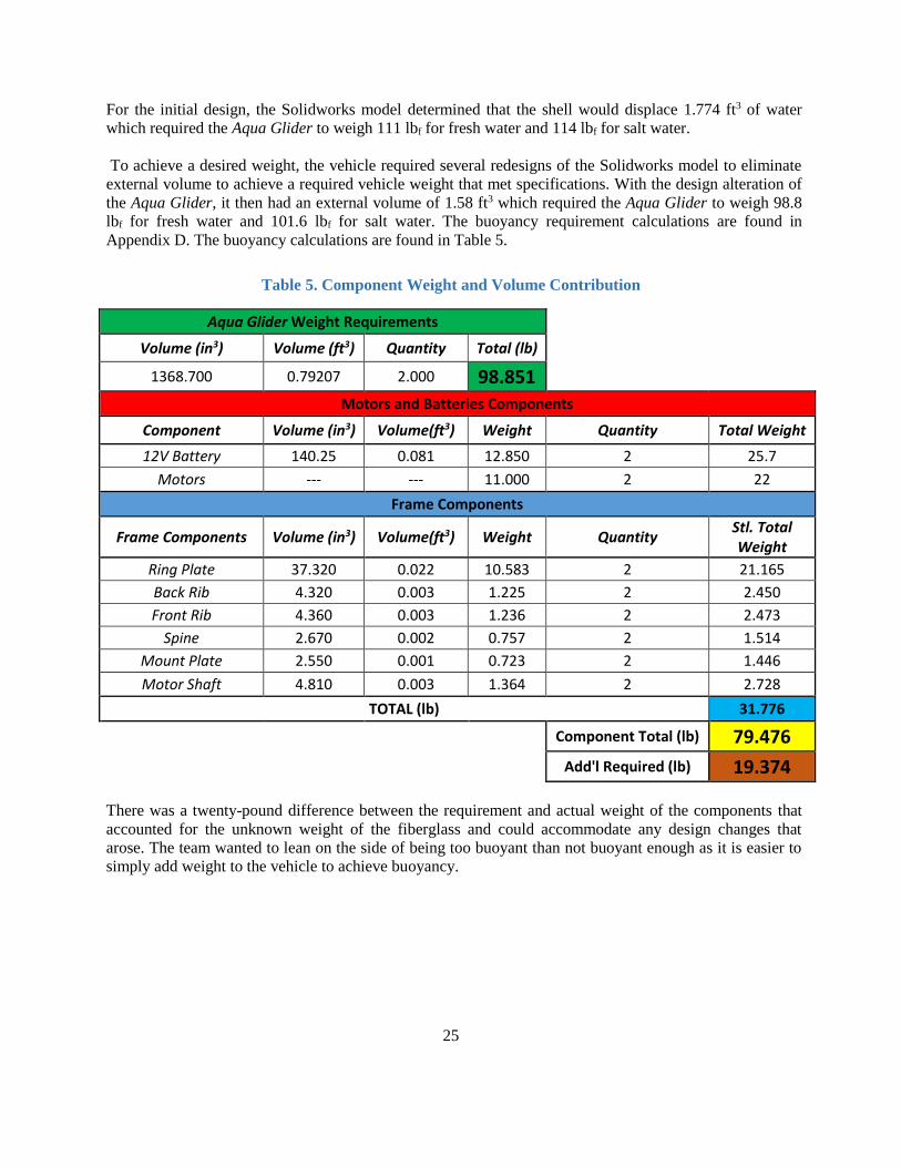
25
For the initial design, the Solidworks model determined that the shell would displace 1.774 ft3 of water
which required the Aqua Glider to weigh 111 lbf for fresh water and 114 lbf for salt water.
To achieve a desired weight, the vehicle required several redesigns of the Solidworks model to eliminate
external volume to achieve a required vehicle weight that met specifications. With the design alteration of
the Aqua Glider, it then had an external volume of 1.58 ft3 which required the Aqua Glider to weigh 98.8
lbf for fresh water and 101.6 lbf for salt water. The buoyancy requirement calculations are found in
Appendix D. The buoyancy calculations are found in Table 5.
Table 5. Component Weight and Volume Contribution
Aqua Glider Weight Requirements
Volume (in3) Volume (ft3) Quantity Total (lb)
1368.700 0.79207 2.000 98.851
Motors and Batteries Components
Component Volume (in3) Volume(ft3) Weight Quantity Total Weight
12V Battery 140.25 0.081 12.850 2 25.7
Motors --- --- 11.000 2 22
Frame Components
Frame Components Volume (in3) Volume(ft3) Weight Quantity Stl. Total Weight
Ring Plate 37.320 0.022 10.583 2 21.165
Back Rib 4.320 0.003 1.225 2 2.450
Front Rib 4.360 0.003 1.236 2 2.473
Spine 2.670 0.002 0.757 2 1.514
Mount Plate 2.550 0.001 0.723 2 1.446
Motor Shaft 4.810 0.003 1.364 2 2.728
TOTAL (lb) 31.776
Component Total (lb) 79.476
Add'l Required (lb) 19.374
There was a twenty-pound difference between the requirement and actual weight of the components that
accounted for the unknown weight of the fiberglass and could accommodate any design changes that
arose. The team wanted to lean on the side of being too buoyant than not buoyant enough as it is easier to
simply add weight to the vehicle to achieve buoyancy.
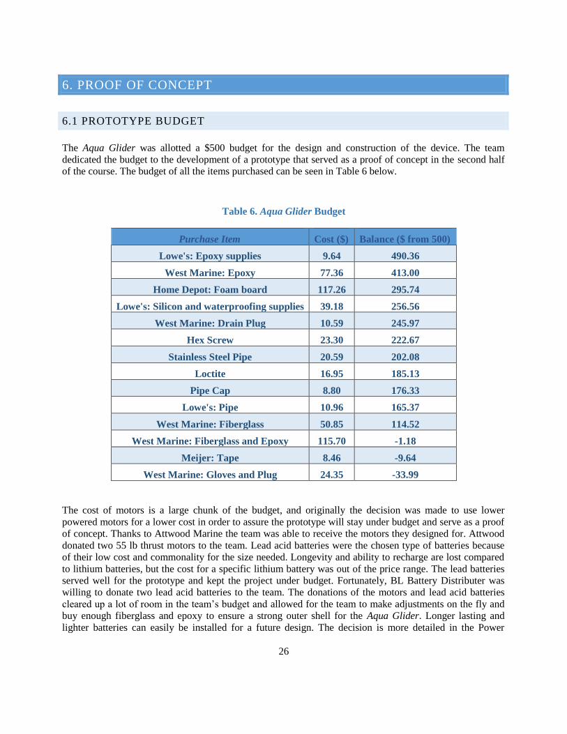
26
6. PROOF OF CONCEPT
6.1 PROTOTYPE BUDGET
The Aqua Glider was allotted a $500 budget for the design and construction of the device. The team
dedicated the budget to the development of a prototype that served as a proof of concept in the second half
of the course. The budget of all the items purchased can be seen in Table 6 below.
Table 6. Aqua Glider Budget
Purchase Item Cost ($) Balance ($ from 500)
Lowe's: Epoxy supplies 9.64 490.36
West Marine: Epoxy 77.36 413.00
Home Depot: Foam board 117.26 295.74
Lowe's: Silicon and waterproofing supplies 39.18 256.56
West Marine: Drain Plug 10.59 245.97
Hex Screw 23.30 222.67
Stainless Steel Pipe 20.59 202.08
Loctite 16.95 185.13
Pipe Cap 8.80 176.33
Lowe's: Pipe 10.96 165.37
West Marine: Fiberglass 50.85 114.52
West Marine: Fiberglass and Epoxy 115.70 -1.18
Meijer: Tape 8.46 -9.64
West Marine: Gloves and Plug 24.35 -33.99
The cost of motors is a large chunk of the budget, and originally the decision was made to use lower
powered motors for a lower cost in order to assure the prototype will stay under budget and serve as a proof
of concept. Thanks to Attwood Marine the team was able to receive the motors they designed for. Attwood
donated two 55 lb thrust motors to the team. Lead acid batteries were the chosen type of batteries because
of their low cost and commonality for the size needed. Longevity and ability to recharge are lost compared
to lithium batteries, but the cost for a specific lithium battery was out of the price range. The lead batteries
served well for the prototype and kept the project under budget. Fortunately, BL Battery Distributer was
willing to donate two lead acid batteries to the team. The donations of the motors and lead acid batteries
cleared up a lot of room in the team’s budget and allowed for the team to make adjustments on the fly and
buy enough fiberglass and epoxy to ensure a strong outer shell for the Aqua Glider. Longer lasting and
lighter batteries can easily be installed for a future design. The decision is more detailed in the Power
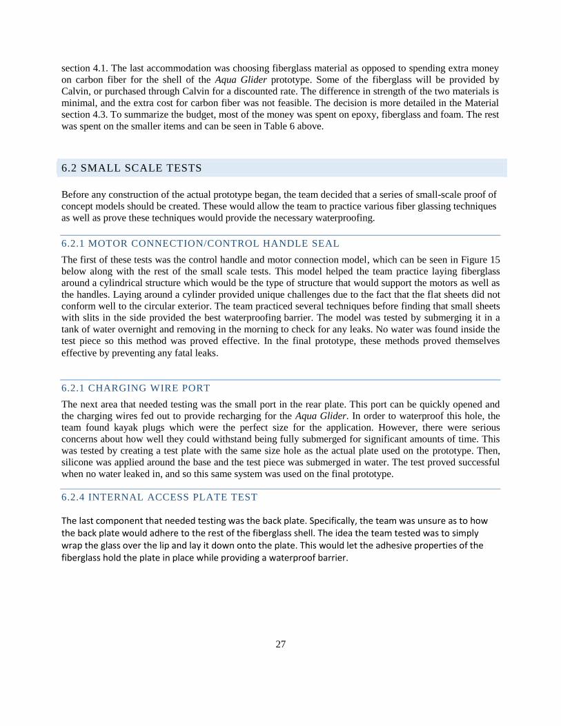
27
section 4.1. The last accommodation was choosing fiberglass material as opposed to spending extra money
on carbon fiber for the shell of the Aqua Glider prototype. Some of the fiberglass will be provided by
Calvin, or purchased through Calvin for a discounted rate. The difference in strength of the two materials is
minimal, and the extra cost for carbon fiber was not feasible. The decision is more detailed in the Material
section 4.3. To summarize the budget, most of the money was spent on epoxy, fiberglass and foam. The rest
was spent on the smaller items and can be seen in Table 6 above.
6.2 SMALL SCALE TESTS
Before any construction of the actual prototype began, the team decided that a series of small-scale proof of
concept models should be created. These would allow the team to practice various fiber glassing techniques
as well as prove these techniques would provide the necessary waterproofing.
6.2.1 MOTOR CONNECTION/CONTROL HANDLE SEAL
The first of these tests was the control handle and motor connection model, which can be seen in Figure 15
below along with the rest of the small scale tests. This model helped the team practice laying fiberglass
around a cylindrical structure which would be the type of structure that would support the motors as well as
the handles. Laying around a cylinder provided unique challenges due to the fact that the flat sheets did not
conform well to the circular exterior. The team practiced several techniques before finding that small sheets
with slits in the side provided the best waterproofing barrier. The model was tested by submerging it in a
tank of water overnight and removing in the morning to check for any leaks. No water was found inside the
test piece so this method was proved effective. In the final prototype, these methods proved themselves
effective by preventing any fatal leaks.
6.2.1 CHARGING WIRE PORT
The next area that needed testing was the small port in the rear plate. This port can be quickly opened and
the charging wires fed out to provide recharging for the Aqua Glider. In order to waterproof this hole, the
team found kayak plugs which were the perfect size for the application. However, there were serious
concerns about how well they could withstand being fully submerged for significant amounts of time. This
was tested by creating a test plate with the same size hole as the actual plate used on the prototype. Then,
silicone was applied around the base and the test piece was submerged in water. The test proved successful
when no water leaked in, and so this same system was used on the final prototype.
6.2.4 INTERNAL ACCESS PLATE TEST
The last component that needed testing was the back plate. Specifically, the team was unsure as to how the back plate would adhere to the rest of the fiberglass shell. The idea the team tested was to simply wrap the glass over the lip and lay it down onto the plate. This would let the adhesive properties of the fiberglass hold the plate in place while providing a waterproof barrier.
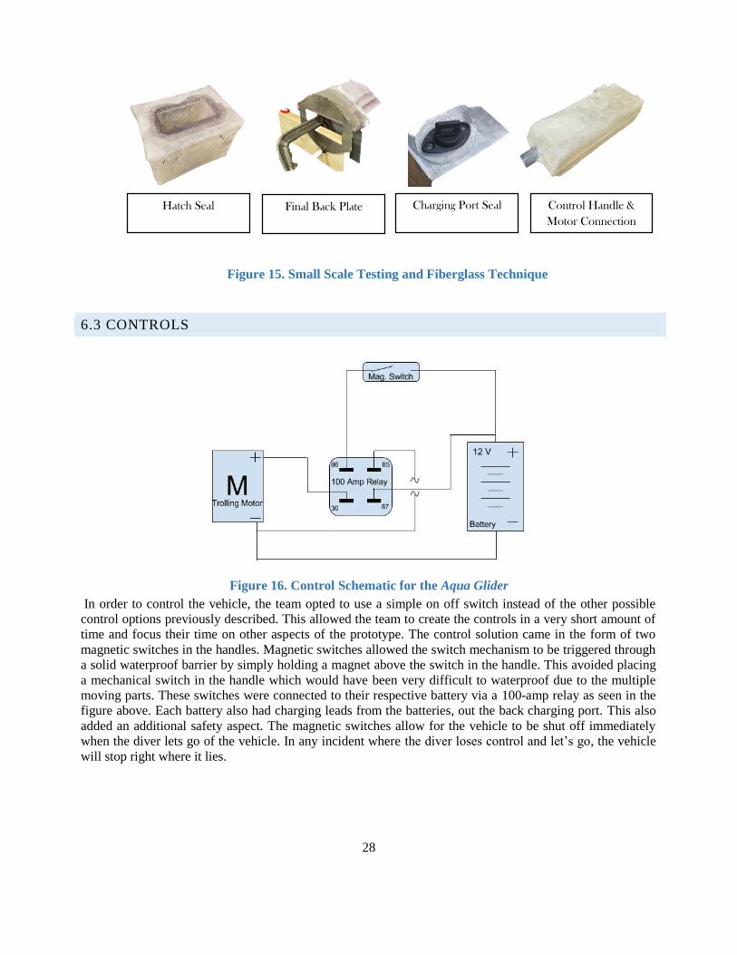
28
Figure 16. Control Schematic for the Aqua Glider
6.3 CONTROLS
In order to control the vehicle, the team opted to use a simple on off switch instead of the other possible
control options previously described. This allowed the team to create the controls in a very short amount of
time and focus their time on other aspects of the prototype. The control solution came in the form of two
magnetic switches in the handles. Magnetic switches allowed the switch mechanism to be triggered through
a solid waterproof barrier by simply holding a magnet above the switch in the handle. This avoided placing
a mechanical switch in the handle which would have been very difficult to waterproof due to the multiple
moving parts. These switches were connected to their respective battery via a 100-amp relay as seen in the
figure above. Each battery also had charging leads from the batteries, out the back charging port. This also
added an additional safety aspect. The magnetic switches allow for the vehicle to be shut off immediately
when the diver lets go of the vehicle. In any incident where the diver loses control and let’s go, the vehicle
will stop right where it lies.
Control Handle &
Motor Connection
Hatch Seal Charging Port Seal Final Back Plate
Figure 15. Small Scale Testing and Fiberglass Technique
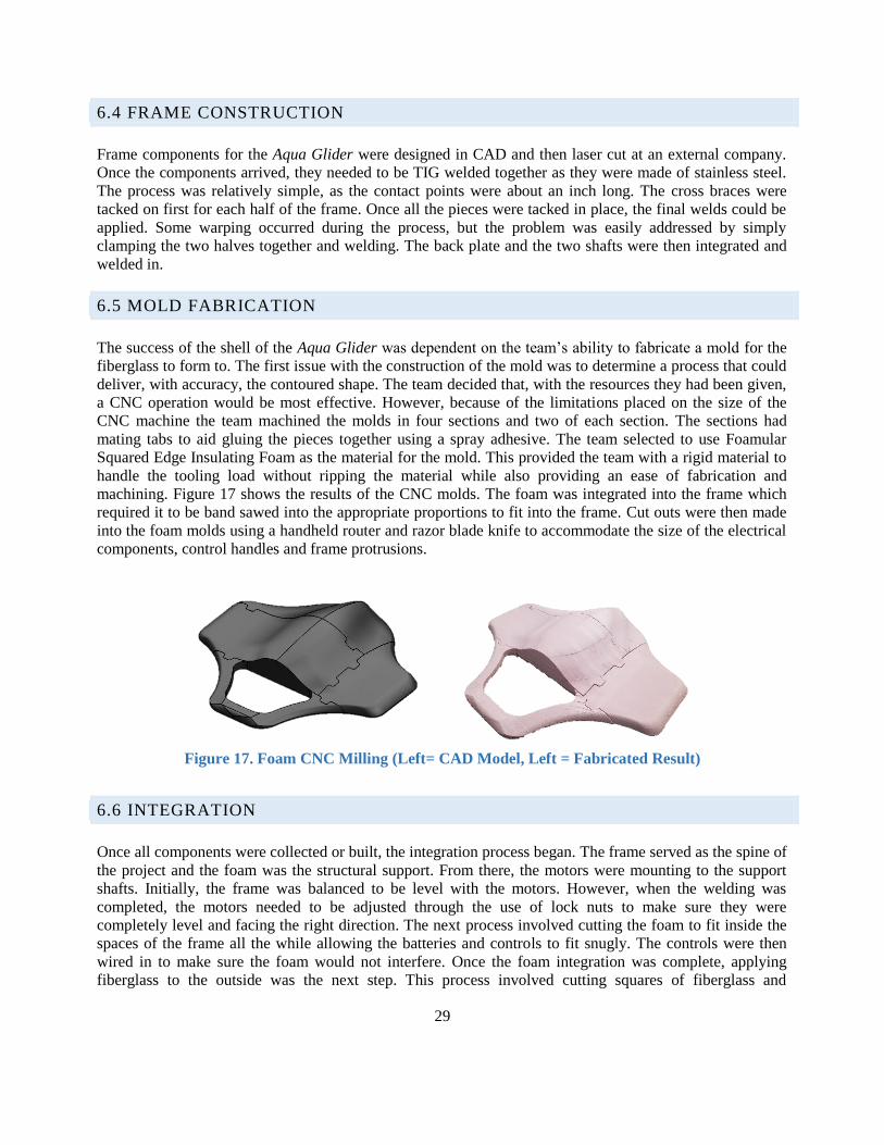
29
6.4 FRAME CONSTRUCTION
Frame components for the Aqua Glider were designed in CAD and then laser cut at an external company.
Once the components arrived, they needed to be TIG welded together as they were made of stainless steel.
The process was relatively simple, as the contact points were about an inch long. The cross braces were
tacked on first for each half of the frame. Once all the pieces were tacked in place, the final welds could be
applied. Some warping occurred during the process, but the problem was easily addressed by simply
clamping the two halves together and welding. The back plate and the two shafts were then integrated and
welded in.
6.5 MOLD FABRICATION
The success of the shell of the Aqua Glider was dependent on the team’s ability to fabricate a mold for the
fiberglass to form to. The first issue with the construction of the mold was to determine a process that could
deliver, with accuracy, the contoured shape. The team decided that, with the resources they had been given,
a CNC operation would be most effective. However, because of the limitations placed on the size of the
CNC machine the team machined the molds in four sections and two of each section. The sections had
mating tabs to aid gluing the pieces together using a spray adhesive. The team selected to use Foamular
Squared Edge Insulating Foam as the material for the mold. This provided the team with a rigid material to
handle the tooling load without ripping the material while also providing an ease of fabrication and
machining. Figure 17 shows the results of the CNC molds. The foam was integrated into the frame which
required it to be band sawed into the appropriate proportions to fit into the frame. Cut outs were then made
into the foam molds using a handheld router and razor blade knife to accommodate the size of the electrical
components, control handles and frame protrusions.
6.6 INTEGRATION
Once all components were collected or built, the integration process began. The frame served as the spine of
the project and the foam was the structural support. From there, the motors were mounting to the support
shafts. Initially, the frame was balanced to be level with the motors. However, when the welding was
completed, the motors needed to be adjusted through the use of lock nuts to make sure they were
completely level and facing the right direction. The next process involved cutting the foam to fit inside the
spaces of the frame all the while allowing the batteries and controls to fit snugly. The controls were then
wired in to make sure the foam would not interfere. Once the foam integration was complete, applying
fiberglass to the outside was the next step. This process involved cutting squares of fiberglass and
Figure 17. Foam CNC Milling (Left= CAD Model, Left = Fabricated Result)
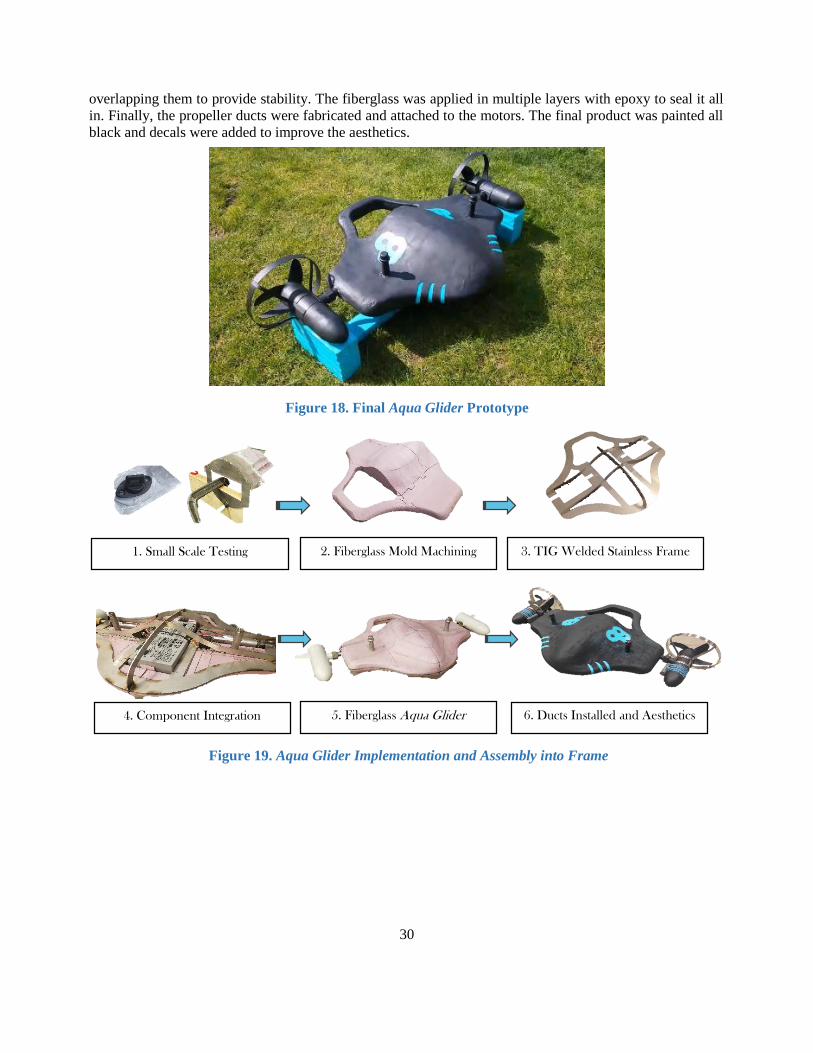
30
Figure 18. Final Aqua Glider Prototype
overlapping them to provide stability. The fiberglass was applied in multiple layers with epoxy to seal it all
in. Finally, the propeller ducts were fabricated and attached to the motors. The final product was painted all
black and decals were added to improve the aesthetics.
1. Small Scale Testing 2. Fiberglass Mold Machining 3. TIG Welded Stainless Frame
4. Component Integration 5. Fiberglass Aqua Glider 6. Ducts Installed and Aesthetics
Figure 19. Aqua Glider Implementation and Assembly into Frame
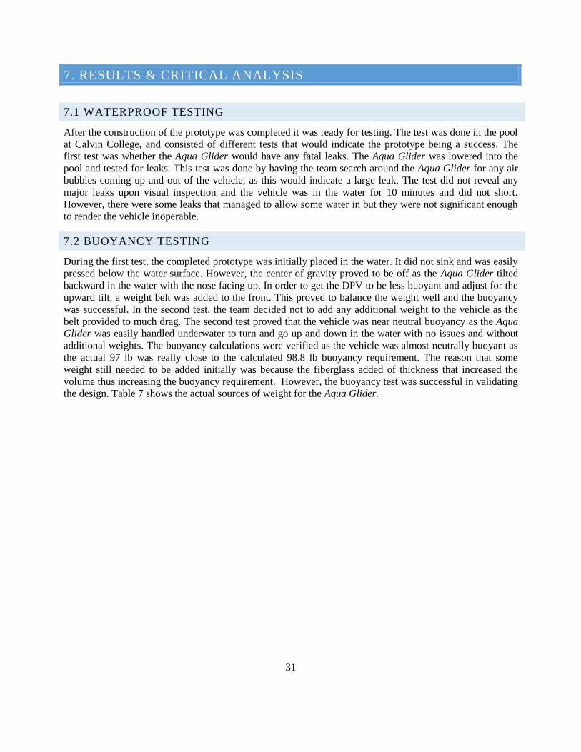
31
7. RESULTS & CRITICAL ANALYSIS
7.1 WATERPROOF TESTING
After the construction of the prototype was completed it was ready for testing. The test was done in the pool
at Calvin College, and consisted of different tests that would indicate the prototype being a success. The
first test was whether the Aqua Glider would have any fatal leaks. The Aqua Glider was lowered into the
pool and tested for leaks. This test was done by having the team search around the Aqua Glider for any air
bubbles coming up and out of the vehicle, as this would indicate a large leak. The test did not reveal any
major leaks upon visual inspection and the vehicle was in the water for 10 minutes and did not short.
However, there were some leaks that managed to allow some water in but they were not significant enough
to render the vehicle inoperable.
7.2 BUOYANCY TESTING
During the first test, the completed prototype was initially placed in the water. It did not sink and was easily
pressed below the water surface. However, the center of gravity proved to be off as the Aqua Glider tilted
backward in the water with the nose facing up. In order to get the DPV to be less buoyant and adjust for the
upward tilt, a weight belt was added to the front. This proved to balance the weight well and the buoyancy
was successful. In the second test, the team decided not to add any additional weight to the vehicle as the
belt provided to much drag. The second test proved that the vehicle was near neutral buoyancy as the Aqua
Glider was easily handled underwater to turn and go up and down in the water with no issues and without
additional weights. The buoyancy calculations were verified as the vehicle was almost neutrally buoyant as
the actual 97 lb was really close to the calculated 98.8 lb buoyancy requirement. The reason that some
weight still needed to be added initially was because the fiberglass added of thickness that increased the
volume thus increasing the buoyancy requirement. However, the buoyancy test was successful in validating
the design. Table 7 shows the actual sources of weight for the Aqua Glider.
32
Table 7. Weight of Aqua Glider Components
Component Weight (lb) Quantity Total Weight
(lb)
Frame
Ring Plate 10.125 2 20.25
Back Rib 1.125 2 2.25
Front Rib 1.188 2 2.375
Spine 0.625 2 1.25
Mount Plate 1.313 1 1.3125
Back plate 0.938 1 0.9375
Motor Shaft 2.394 2 4.788
Control Handles 0.450 2 0.9
Nuts 0.400 2 0.8
Motors and Batteries
Battery 12.85 2 25.7
Motors w/propellers 11.4375 2 22.875
Other Component Total Sum
Fiberglass, Wire, Relay and Foam
13.562 1 13.562
Total Weight (lb) 97
The buoyancy calculations were verified as the vehicle was almost neutrally buoyant as the actual 97 lb was
really close to the calculated 98.8 lb buoyancy requirement. The reason that some weight still needed to be
added is because the fiberglass added a few layers of thickness that increased the volume thus increasing the
buoyancy requirement. However, the buoyancy test was successful in validating the design.
7.3 SPEED TEST
The Aqua Glider was modeled in CAD and a calculation model was performed to determine the speed the
Aqua Glider would be able to reach, and more information on this can be seen in section 5.2. There were
some unknowns between the calculation modeling and reality, so to test the speed, the distance between
lines in the pool was measured and the time it took to get from one line to the next in a straight line was
measured. Using this experiment the Aqua Glider was able to reach a speed of about 3 mph. This did not
reach the speed that our calculation models produced, but there were unknowns in the drag coefficient of
the diver, complexities in how the diver interacts with the vehicle and unknown with how the thrust changes
statically vs dynamically. Another source of uncertainty was whether the fact that the motors and propellers
were made in such a way that they were oriented and spun in the same direction which renders the
possibility that some of the force vectors cancel each other out delivering less speed than desired. However,
a likely reason that the Aqua Glider did not reach a speed of 5 mph design is because the drag coefficients
of the diver and SCUBA tanks used were not accurate, as the information found on these numbers were
very inconsistent. Therefore, the team revisited the calculations and research to recalculate the drag. Based
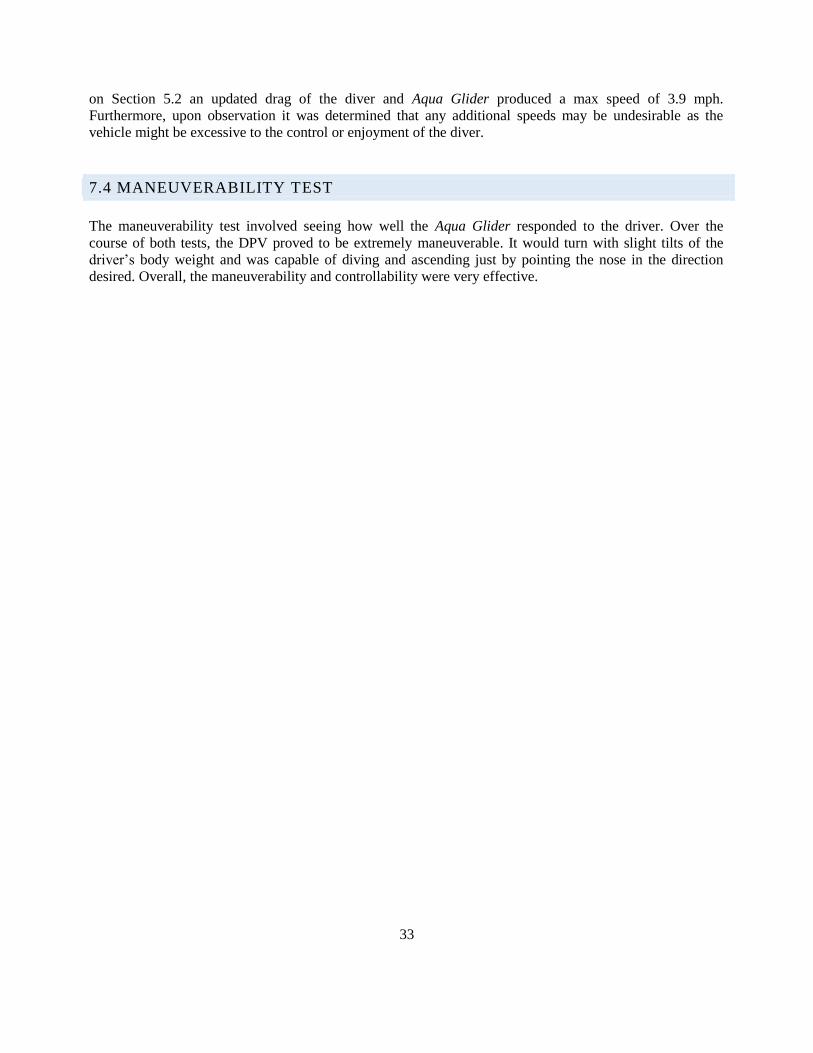
33
on Section 5.2 an updated drag of the diver and Aqua Glider produced a max speed of 3.9 mph.
Furthermore, upon observation it was determined that any additional speeds may be undesirable as the
vehicle might be excessive to the control or enjoyment of the diver.
7.4 MANEUVERABILITY TEST
The maneuverability test involved seeing how well the Aqua Glider responded to the driver. Over the
course of both tests, the DPV proved to be extremely maneuverable. It would turn with slight tilts of the
driver’s body weight and was capable of diving and ascending just by pointing the nose in the direction
desired. Overall, the maneuverability and controllability were very effective.
34
8. PRODUCTION DESIGN
8.1 CONTROL ADD-ONS
The prototype controls were designed with a simple on/off magnetic switch, as seen in more detail in
section 7.3. In production the Aqua Glider would have two more control options, and those two control
options are variable speed and a ballast tank control system. Both the variable speed and ballast tank would
still run off of the main battery, and the controls would still remain simple. To add the variable speed would
only change the switch, as trolling motors are already designed for variable speed. A ballast tank would
need to add an air cylinder to adjust the weight of the Aqua Glider in water. The details of the size and type
of air cylinder can be seen in section 5.4.
8.2 MATERIAL SELECTION
The prototype material selections included using a foam mold and a fiberglass shell to make the frame.
However, in production it would be much more cost effective to use some sort of a metal or plastic exterior
that can be stamped for a contoured shape. Research concluded that plastic would be more convenient in
production and is more affordable [17]. To ensure structural integrity the plastic mold would consist of an
internal frame, but crush tests would be done to find the optimal solution. The process to produce such a
contoured shape in higher production for the size of the Aqua Glider would be thermoforming. This would
be done by reaching out to a company that specializes in thermoforming production, like Rapid X
Engineering.
8.3 COMPONENT SELECTION
Initially the team was going to purchase critical components such as the Power Sonic PS-12180 lead acid
battery at $40 per unit. Additionally, it was necessary to purchase two Endura C2 40 trolling motors from
Minn Kota at a price of $153 per unit. However, thanks to generous donations from B.L. Battery
Distributors, Team 26 was able to acquire two 18 Ah lead acid batteries for free. Along with that, another
generous donation came from Attwood Marine with two 55 lb. thrust motors. The team decided to use a
dense foam for the fiberglass mold as it would provide more structure. Additionally, stainless steel was
selected for the frame because of its corrosion resistant properties and structural integrity. All additional
metal components such as handles and supports were made from steel. Because of the uncommon thread
associated with the motors, additional bolts with matching threads were purchased and welded to the
support shafts.
35
9. BUSINESS PLAN
9.1 MARKET RESEARCH
According to a study conducted by the Diving Equipment & Marketing Association (DEMA) in 2014, there
are somewhere between 2.7 and 3 million active recreational SCUBA divers in the United States (140,000
new divers per year) and around 6 million active divers worldwide that serve as the market basis for the
Aqua Glider. According to the same study, the average age of a SCUBA diver is around 30 years.
Additionally, 64% of divers have an annual income between $100,000 and $150,000. There is about $11
billion dollars in recreational SCUBA and snorkeling that add to the US GDP. The total average revenue
made off a SCUBA diver is $1,910. With high concerns, the SCUBA market is saturated with products that
are designed for quality. While quality doesn’t always insinuate an increase in price, the SCUBA market
definitely is not an inexpensive recreational activity. Therefore, while minimizing cost is a concern for the
Aqua Glider, the performance and quality of the vehicle should not be traded off. [15]
9.2 COMPETITIVE STRATEGY
The Aqua Glider is not the only SCUBA mobility solution on the market, therefore the team did extensive
research into a number of other DPV products. A tabulated and graphical summary of the results can be
found in Appendix F. Through the comparison of many different products, it was determined that in order
to give the Aqua Glider a competitive edge, it must be capable of speeds higher than other DPVs while still
maintaining the runtime and depth rating that are characteristic of recreational dives. Another key
component is providing the Aqua Glider with navigational controls, to minimize the body movement
necessary to turn the DPV; an innovative part of the solution not seen on most current DPV’s. Largely, the
Aqua Glider is being developed to set a new level of control and speed in the DPV market.
9.3 SWOT ANALYSIS
9.3.1 STRENGTHS
The Aqua Glider provides a recreational diver with a unique and new hydrodynamic shape that will
accommodate dual propellers for speeds higher than most of the competitor DPV’s. Divers looking for
more power out of a DPV will be drawn to the Aqua Glider. The dual propeller also allows for a more
dynamic turning control feature. The turning controls will be less cumbersome to the diver as he attempts to
maneuver under water. DPV’s allow for divers to explore greater distances more efficiently, and therefore
appeal to many divers looking to explore a larger area while exerting less energy and using less oxygen to
do so.
9.3.2 WEAKNESSES
The Aqua Glider is going to be larger and wider than many of the DPV’s that have been developed. This is
a tradeoff the team considered to achieve the extra power, however divers looking to explore spaces with
tighter features may shy away from the Aqua Glider. Furthermore, DPV’s have a learning curve associated
36
with their operation and consequently, non-frequent divers may not justify the learning time required by a
DPV worth the investment.
9.3.3 OPPORTUNITIES
Divers are willing to spend money in a market where flippers alone can cost upwards of $200, dive suits
around $500, and regulators around $300. Therefore, there is a strong client basis willing to spend money
on high quality, specialty operational products. Developing the Aqua Glider could also motivate companies
to come up with competitive products, pushing DPV technology to new levels.
9.3.4 THREATS
The recreational activity of SCUBA for most people requires that they either have access or have the
financial means to travel to a body of water. The market is relatively narrow and fluctuates based on the
economy more than many other products because it is considered a luxury item. Environmental threats also
need to be considered as contamination of diving sites through pollution or other environmental factors may
take some of the allure of recreational diving away. The presence of other DPV’s on the market may
distract divers from selecting the Aqua Glider.
37
10. CONCLUSION
10.1 TAKEAWAYS
As the Aqua Glider started to go from an idea on paper to a prototype vehicle, the risks seemed
overwhelming. The team quickly learned there can never be too much preparation as small scale testing
proved some of the challenges on waterproofing the Aqua Glider. All of the calculations and research
helped the team get a great sense of the vehicle they were building, but the process of building a
prototype was a steep learning curve. Knowing the correct materials and methods was essential on
building a working vehicle. One of the main lessons the team learned was that there can never be too
much planning that goes into a project. Whether it is planning for some failures, or planning on other
options if one plan is out of budget the more planning the better a team is set up for success.
With that lesson came another, do not dwell on the past. The team did not plan for everything, but the
best way to solve the problem is to take it head on and not dwell on what the team should have done
differently. There is always a solution out there, it's just a matter of finding the best solution and fixing
the problem to get back on track.
A team is a makeup of different individuals who are all different in how they work and act, and to ensure
good team chemistry a team must have good communication. Schedules for available time to work do not
always line up, so communicating on the tasks finished and what needs to be done is essential for a good
team.
Finally, completing a project makes all of the trials and tribulations worth it. It takes a long time for a
project to become a reality, but there is a lot of satisfaction is finalizing a project.
10.2 SUMMARY
Overall, the Aqua Glider team ended the year with a fully functional prototype that exceeded the team's
expectations in many ways. Team 26 used each member’s skills and talents to develop a DPV that is
functional, safe, and fun to use. The team predicted issues and overcame unforeseen obstacles that arose.
The team strove to incorporate design norms and bring honor to both God and Calvin College through the
accomplishments achieved with the Aqua Glider.
38
11. ACKNOWLEDGEMENTS
Team 26 would like to cordially thank all their supporters, friends and family for their support over the
year here at Calvin and through the duration of this project. There are a few names we would like to
specifically mention:
Team Advisor: Professor Renard Tubergen
Professor Tubergen has invested in the development of the team as engineers and as individuals through
the courses he has taught. Professor Tubergen also served as a crucial technical support for this project.
The team would also like to thank him for the taking the time to instruct us how to SCUBA dive and
being a constant resource.
Materials and Design Consultant: Mr. Phil Jasperse
Phil Jasperse instructed the team in the proper mechanics of metal fabrication. He also served as a key
resource during the construction and material selection processes involved in the prototype
development. His input in the design helped solve many challenging obstacles.
Parts Distributor: Bob Dekracker
Bob Dekracker was instrumental in organizing the delivery of ordered parts to the team and ensuring
the team had what it needed to complete the project.
Parts Distributor: Michelle Krul
Michelle Krul is the engineering departments administrative assistant and was instrumental in
preparing the team for and organizing the Senior Design Night. The team is very appreciative and
cannot overlook all her help over the years at Calvin College.
Donor: Attwood Marine
Attwood Marine donated the trolling motors to the development of the Aqua Glider. The team is
extremely grateful for their support and investment.
Donor: B.L Battery Distributors
B.L Battery Distributors donated the 12 V batteries to the development of the Aqua Glider. The team
really appreciate their contributions as it helped them meet their budget goals.
SCUBA Gear Provider: American Dive Zone
American Dive Zone equipped the team with necessary equipment to start SCUBA training so that they
could effectively test their product.
Logo Designer: Micah Veldkamp
Micah Veldkamp donated his graphic design services to the team. He developed the logo for the team
and was instrumental in giving the team a further sense of identity.
39
12. CITATIONS [1] "Understanding Ocean Acoustics." NOAA Ocean Explorer Podcast RSS. NOAA Ocean Explorer Webmaster, 06 Apr. 2015.
Web. 12 Dec. 2016. http://oceanexplorer.noaa.gov/explorations/sound01/background/acoustics/acoustics.html [2] Freitas, Christopher. "SolarPro Magazine." High-Capacity Battery Banks | SolarPro Magazine. Home Power Inc,
2016. Web. 12 Dec. 2016. http://solarprofessional.com/articles/products-equipment/batteries/high-capacity-battery-banks
[3] Wood, T.D. "Batteries: How to Choose." REI. Recreational Equipment, IncRecreational Equipment, Inc, 2016. Web. 12 Dec.
2016. https://www.rei.com/learn/expert-advice/batteries.html [4] "12v or 24v or Something Else? - 4QD - Electric Motor Control." 4QD - Electric Motor Control. 4QD Ltd., 2016.
Web. 12 Dec. 2016.http://www.4qd.co.uk/docs/12-24-36-or-48v-operation/ [5] 24 Volt Electric Scooter and Bicycle Motors - ElectricScooterParts.com. ElectricScooterParts.com, 2016. Web. 12 Dec.
2016.https://electricscooterparts.com/motors24volt.html [6] "Buoyancy, Stability, and Ballast 1 Cornerstone Electronics Technology and Robotics Cornerstone University, n.d. Web. 12
Dec. 2016. http://cornerstonerobotics.org/curriculum/lessons_year3/eriii9_buoyancy1.pdf [7] Hirata, Koichi and Sysuke Kawai. "Prototype Fish Robot, UPF-2001." Hydrodynamic Performance of Stream-lined Body.
N.p., 15 Nov. 2001. Web. 12 Dec. 2016. https://www.nmri.go.jp/eng/khirata/fish/experiment/upf2001/body_e.html [8] Factors That Effect Drag. NASA, 15 May 2015. Web. 12 Dec. 2016. https://www.grc.nasa.gov/www/k-
12/airplane/factord.html [9] Shapiro, Thomas A. The Effect of Surface Roughness on Hydrodynamic Drag and Turbulence. N.p., 2004. Web.
12 Dec. 2016. http://www.dtic.mil/dtic/tr/fulltext/u2/a424978.pdf [10] "Material Selection Guide." Nitrile (Buna-N) - Material Selection Guide | Apple Rubber Products. Apple Rubber
Products, n.d. Web. 12 Dec. 2016. http://www.applerubber.com/seal-design-guide/material-selection-guide/nitrile-buna-n.cfm [11] Albert, JD. On-Ramp to Design Engineering: Sealing. Bresslergroup, 13 Feb. 201. Web. 12 Dec. 2016.
http://www.bresslergroup.com/blog/design-engineering-sealing-products/ [12] O-Rings. Apple Rubber, n.d. Web. 12 Dec. 2016. http://www.applerubber.com/products/o-rings.cfm [13] ASM Material Data Sheet. N.p., n.d. Web. 12 Dec. 2016.
http://asm.matweb.com/search/SpecificMaterial.asp?bassnum=MA6061t6 [14] Fiberglass and Composite Material Design Guide. Performance Composites Inc., n.d. Web. 12 Dec. 2016.
http://www.performancecomposites.com/about-composites-technical-info/122-designing-with- fiberglass.html [15] "Fast Facts: Recreational SCUBA Diving and Snorkeling." Diving Equipment and Marketing Association (DEMA), 2014.
Web. 12 Dec. 2016. http://www.dema.org/store/download.asp?id=7811B097-8882-4707-A160-F999B49614B6 [16] Vilas-Boas, J. Paulo. Hydrodynamics of Drag in Human Swimming. U. Porto, n.d. Web. 12 Dec. 2016.
http://www.fade.up.pt/docentes/leandromachado/biomecanica/Hydrod-Drag.pdf

40
[17] Revan. "Diving Safely Without A BC." SCUBABoard. N.p., 28 May 2016. Web. 09 May 2017. https://www.SCUBAboard.com/community/threads/diving-safely-without-a-bc.525866/page-14
41
13. APPENDIX
APPENDIX TABLE OF CONTENTS
Appendix A: Project Scheduling………………………………………………………………………....42
Appendix B: Thrust Determinations………………......…………………………………………………43
Appendix C: Buoyancy Determinations ………………………………… ……………………………46
Appendix D: FMEA Analysis……………………………………………………………………………48
Appendix E: Market Research...…………………………………………………………………………49
Appendix F: Final CAD Renderings.…………………………………………………………………….50
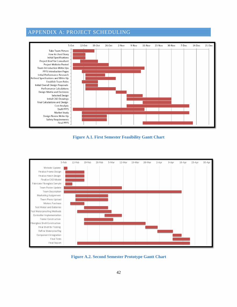
42
APPENDIX A: PROJECT SCHEDULING
Figure A.1. First Semester Feasibility Gantt Chart
Figure A.2. Second Semester Prototype Gantt Chart
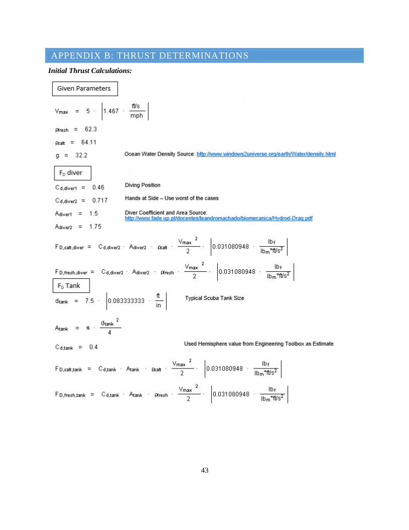
43
APPENDIX B: THRUST DETERMINATIONS
Initial Thrust Calculations:
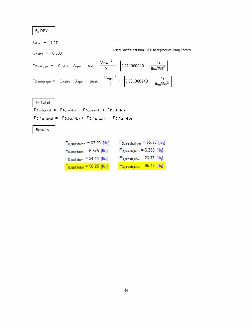
44
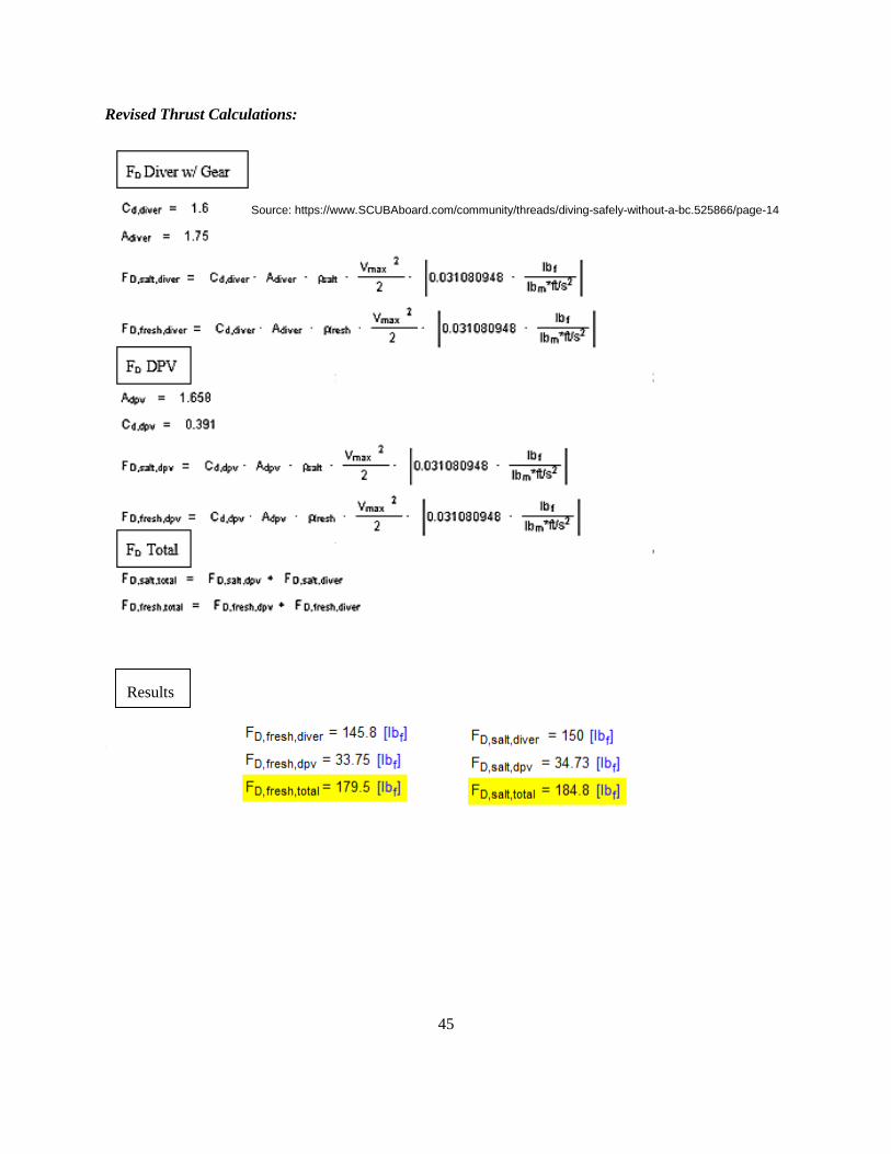
45
Results
Revised Thrust Calculations:
‘
Source: https://www.SCUBAboard.com/community/threads/diving-safely-without-a-bc.525866/page-14
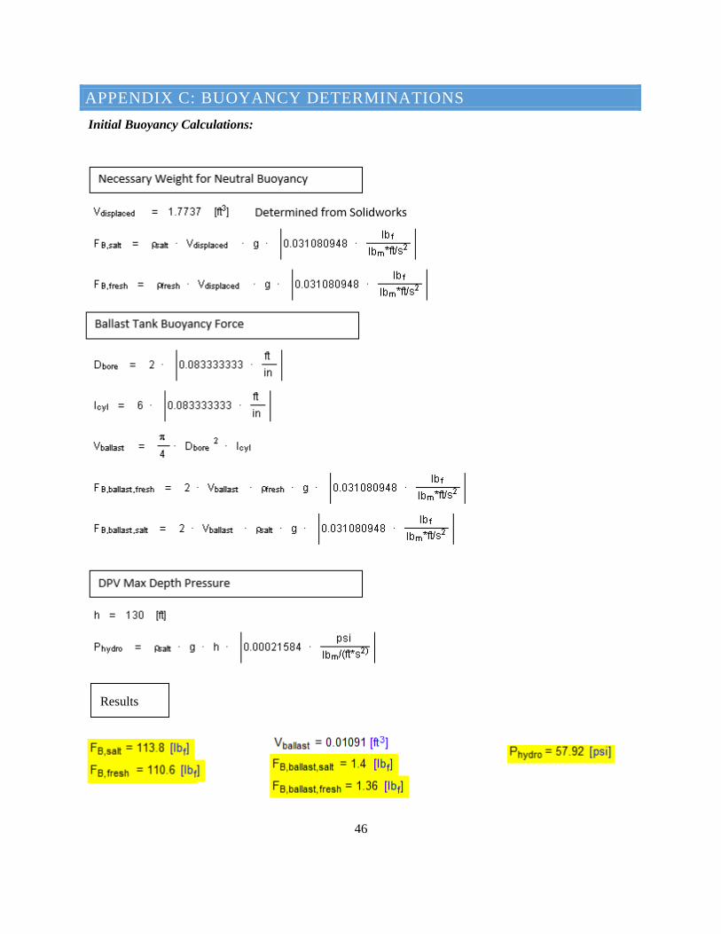
46
APPENDIX C: BUOYANCY DETERMINATIONS
Initial Buoyancy Calculations:
Results
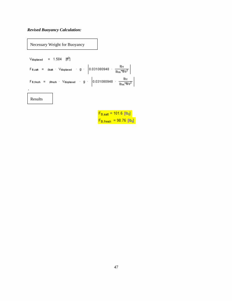
47
Revised Buoyancy Calculation:
Results
Necessary Weight for Buoyancy
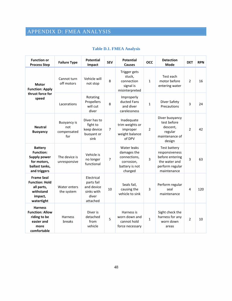
48
APPENDIX D: FMEA ANALYSIS
Table D.1. FMEA Analysis
Function or Process Step
Failure Type Potential Impact
SEV Potential
Causes OCC
Detection Mode
DET RPN
Motor Function: Apply thrust force for
speed
Cannot turn off motors
Vehicle will not stop
8
Trigger gets stuck,
connection signal is
misinterpreted
1 Test each
motor before entering water
2 16
Lacerations
Rotating Propellers
will cut diver
8
Improperly ducted Fans
and diver carelessness
1 Diver Safety Precautions
3 24
Neutral Buoyancy
Buoyancy is not
compensated for
Diver has to fight to
keep device buoyant or
sink
7
Inadequate trim weights or
improper weight balance
of DPV
2
Diver buoyancy test before
descent, regular
maintenance of design
2 42
Battery Function:
Supply power for motors,
ballast tanks, and triggers
The device is unresponsive
Vehicle is no longer functional
7
Water leaks damages the connections,
corrosion, battery is not
charged
3
Test battery responsiveness before entering the water and
perform regular maintenance
3 63
Frame Seal Function: Hold
all parts, withstand
impact, watertight
Water enters the system
Electrical parts fail
and device sinks with
diver attached
10 Seals fail,
causing the vehicle to sink
3 Perform regular
seal maintenance
4 120
Harness Function: Allow
riding to be easier and
more comfortable
Harness breaks
Diver is detached
from vehicle
5
Harness is worn down and
cannot hold force necessary
1
Sight check the harness for any
worn down areas
2 10
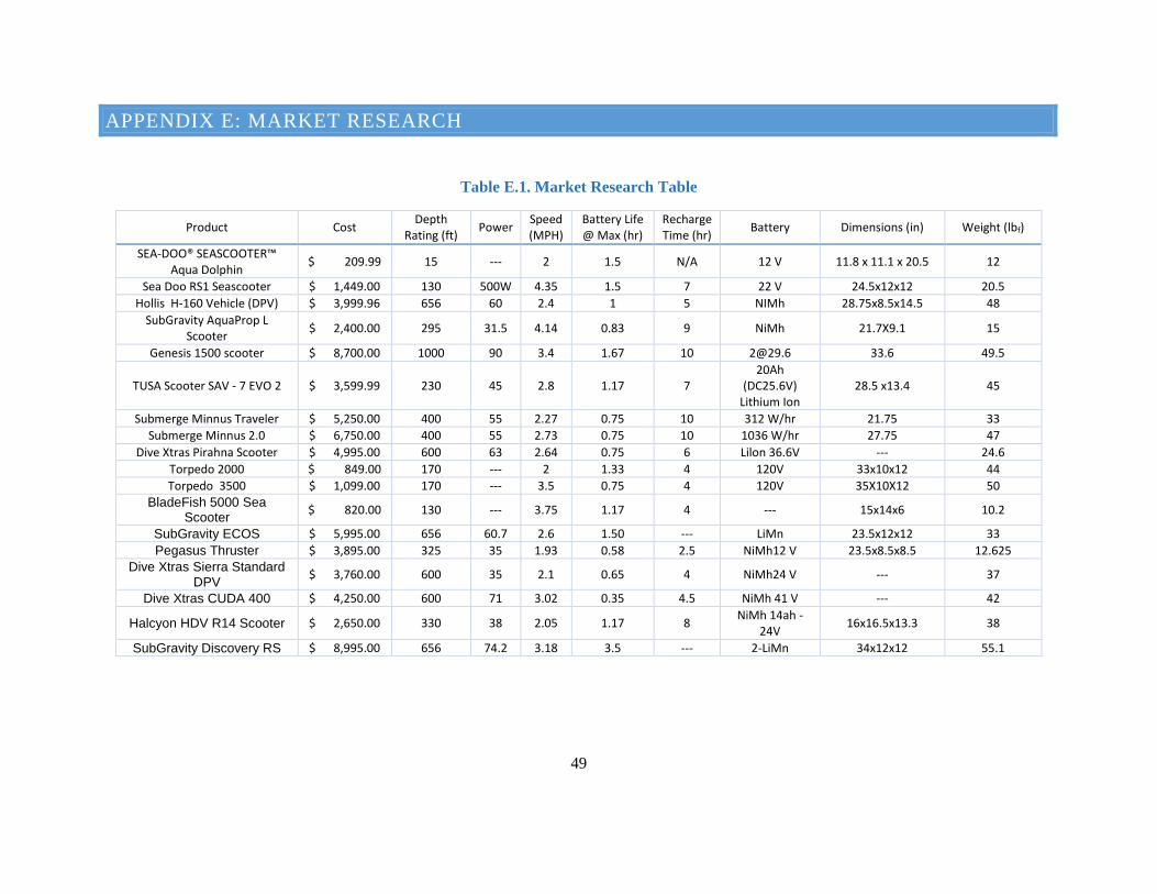
49
APPENDIX E: MARKET RESEARCH
Table E.1. Market Research Table
Product Cost Depth
Rating (ft) Power
Speed (MPH)
Battery Life @ Max (hr)
Recharge Time (hr)
Battery Dimensions (in) Weight (lbf)
SEA-DOO® SEASCOOTER™ Aqua Dolphin
$ 209.99 15 --- 2 1.5 N/A 12 V 11.8 x 11.1 x 20.5 12
Sea Doo RS1 Seascooter $ 1,449.00 130 500W 4.35 1.5 7 22 V 24.5x12x12 20.5
Hollis H-160 Vehicle (DPV) $ 3,999.96 656 60 2.4 1 5 NIMh 28.75x8.5x14.5 48
SubGravity AquaProp L Scooter
$ 2,400.00 295 31.5 4.14 0.83 9 NiMh 21.7X9.1 15
Genesis 1500 scooter $ 8,700.00 1000 90 3.4 1.67 10 [email protected] 33.6 49.5
TUSA Scooter SAV - 7 EVO 2 $ 3,599.99 230 45 2.8 1.17 7 20Ah
(DC25.6V) Lithium Ion
28.5 x13.4 45
Submerge Minnus Traveler $ 5,250.00 400 55 2.27 0.75 10 312 W/hr 21.75 33
Submerge Minnus 2.0 $ 6,750.00 400 55 2.73 0.75 10 1036 W/hr 27.75 47
Dive Xtras Pirahna Scooter $ 4,995.00 600 63 2.64 0.75 6 Lilon 36.6V --- 24.6
Torpedo 2000 $ 849.00 170 --- 2 1.33 4 120V 33x10x12 44
Torpedo 3500 $ 1,099.00 170 --- 3.5 0.75 4 120V 35X10X12 50
BladeFish 5000 Sea Scooter
$ 820.00 130 --- 3.75 1.17 4 --- 15x14x6 10.2
SubGravity ECOS $ 5,995.00 656 60.7 2.6 1.50 --- LiMn 23.5x12x12 33
Pegasus Thruster $ 3,895.00 325 35 1.93 0.58 2.5 NiMh12 V 23.5x8.5x8.5 12.625
Dive Xtras Sierra Standard DPV
$ 3,760.00 600 35 2.1 0.65 4 NiMh24 V --- 37
Dive Xtras CUDA 400 $ 4,250.00 600 71 3.02 0.35 4.5 NiMh 41 V --- 42
Halcyon HDV R14 Scooter $ 2,650.00 330 38 2.05 1.17 8 NiMh 14ah -
24V 16x16.5x13.3 38
SubGravity Discovery RS $ 8,995.00 656 74.2 3.18 3.5 --- 2-LiMn 34x12x12 55.1
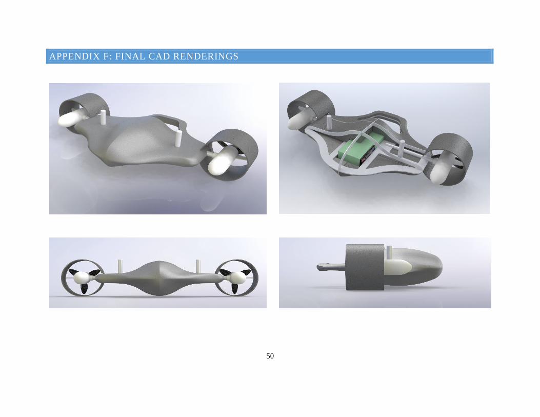
50
APPENDIX F: FINAL CAD RENDERINGS