Embed Size (px)
Citation preview
1Aqua Control, Inc. 60 Hz. Titan Series Instruction Manual
Aqua Control, Inc.60 Hz. TITAN SERIES INSTRUCTION MANUAL
PRE-ASSEMBLYAny components that have been removed from the packages and installed in the water will have a higher restocking fee if it is later determined that they have been ordered incorrectly and need to be returned to the factory and exchanged. Keep your original packaging for returns to the factory or contact the factory for packaging suitable for safe return of the product.
1. Check the packing list that came with the shipment. Make certain all the boxes have been received. Each label will have a box number and total for the shipment (1 of 5, 2 of 5). The packing list has the total number of boxes noted at the bottom.
2. Check the pond depth. Is the pond deep enough for the unit being installed?
3. Verify the incoming voltage where it will be connected to the control panel. Does the measured voltage match the rated motor voltage requirements? Note the HP, voltage and phase on the packing list.
4. Is there a VFD operating from the same power supply or in the vicinity that might interfere with the GFCI?
TABLE OF CONTENTS
Copyright 2008. All Rights Reserved.
PAGE
Safety 1
Assembly Titan Series Vertical 2 Titan Series Horizontal 2
Nozzles Nozzle Types (Type 1-5) 3-5Lights 6-7
Cord Pump Cord Connectors 8 T-Connectors 9 Splice Info 10
Titan Series Mooring 11 Titan Series Anchoring 12
Lifting the Unit 13 Placing Unit in Water 14
Control Panels Installation 15 Start-Up 16
Flotation 16
Freezing Weather Removal of Unit 17
Troubleshooting General 18 Cord 19 Motor Control Box 20-21 Overload 22
SAFETY INFORMATION
WARNINGThis product is not intended for use by young children or infirm persons unless they have been adequately supervised by a responsible person to ensure that they can operate the product safely.
Young children should be supervised to ensure that they do not play with the product.
Your Aqua Control, Inc. products are made entirely of corrosion resistant materials including stainless steel, aluminum alloy, bronze and engineered plastics. They will provide safe, long and satisfactory service if properly installed, operated and maintained.
1. Follow all applicable local and state electrical codes. 2. Protect exposed or vulnerable wiring with tubing or conduit. 3. Do not operate the unit when it is obvious the flow rate is reduced. 4. Do not work on the unit when it is turned on or operating. 5. Follow all normal safety precautions when working in and around the water. 6. Prevent tension on the electrical wires. 7. Do not carry or pull the unit by the lights or by the cord. Use the finger pockets on the float. 8. Never try to dislodge debris from the impeller or propeller while the motor is connected to the power supply. 9. Always make certain that the control panel and all electrical equipment is grounded properly.
10. Any time high voltage electricity is used underwater, a potential safety hazard exists. Aqua Control builds and provides UL listed control panels that are standard equipped with a Class A Ground Fault Circuit Interrupter (GFCI) for both motors and lights. Class A GFCI’s are designed to provide protection against electrocution for people. They have a nominal trip level of 5 ma (milli amps=.005 amps) and are designed to shut the circuit off in 25 milli seconds. Such a system will shut off a current resulting from shorts or dangerous leakage, whether from the motor, electrical cables, or controls, before a hazardous current can develop.
PAGE PAGE
2 Aqua Control, Inc. 60 Hz. Titan Series Instruction Manual
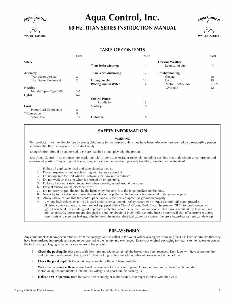
TITAN SERIESHORIZONTAL FOUNTAIN
1. Remove straps holding the fountain to the pallet and remove any cartons that were shipped with the fountain on the pallet. (lights, cord, etc.). See diagram. DO NOT CUT SUPPORT STRAPS
2. Inspect for any visible damage that may have occurred during shipping.
Contact Aqua Control, Inc. immedi-ately if any damage is found. DO NOT CUT THE SUPPORT STRAPS holding the discharge to the lower pump.
3. See the nozzle, cord and light instruc-tions for attaching these to the unit.
Horizontal Titan units are shipped fullyassembled on a shipping pallet.
FLOATS
STRAPS TO BE REMOVED
PALLET
DO NOT CUT
MOTOR LEAD
SUCTION SCREENS
HEAD
TITAN SERIESVERTICAL FOUNTAIN ASSEMBLY
1. Remove the 12” lower pump assembly from its crate and inspect the fountain for any visible damage that might have oc-curred during the shipping process.
2. Find the hardware inside the crate for attaching the upper tube assem-bly to the lower pump and the flange gasket. (The threads of the bolts are coated with anti-seize to make dis-assembly easier if needed in the future.)
3. Prop the upper end of the 12” lower pump assembly on a 15”-18” stable box or other suitable heavy-duty container so that the unit is as shown in diagram.
4. Take the (8) eight screws with flat wash-ers and hex nuts out of the hardware box. Take the (2) two hex nuts and (1) one of the flat washers off each of the bolts. Leave (1) one flat washer on each bolt.
5. Put (2) two of these bolts with flat washer through (2) two of the holes in the flange on the lower pump with the hex head toward the pump. Place the flange gasket on the bolts lining up all of the holes.
BOLTS
6. Line up the flange of the upper tube with the lower pump flange pushing the bolts through both flanges. Place a flat washer on each bolt and thread a hex nut onto each bolt.
7. Put the (6) six remaining screws through the (2) two flanges with a flat washer and hex nut on each bolt. Tighten these bolts securely.
8. Thread another hex nut onto each bolt and tighten against the first nut locking them in place.
9. Attach mooring/anchoring lines to the float eye bolts located under the upper float.
10. See nozzle, light and cord instructions for attaching these to the unit.
UPPER TUBE WITH FLOATS & HEAD
FLANGES
NUTS
GASKETS
12” LOWER PUMP

3Aqua Control, Inc. 60 Hz. Titan Series Instruction Manual
NOZZLES
Find the nozzle that is being attached to this unit in the table below. This table will tell you which of the five nozzle types a nozzle falls under to locate the correct instructions.
FOUNTAIN NOZZLES NOZZLE TYPE
Arch Type 1
Candelabra Type 1
Daffodil Type 2
Lily Type 2
Quad Type 1
Scepter Type 1
Buckingham Type 1
Double Trellis Type 1
Flare and Sky Geyser Type 4
Fleur de Lis Type 1
Full Geyser Type 3
Geyser Type 3
Majestic Type 1
Shooting Star Type 1
Sky Geyser Type 1
Spoke and Trellis Type 1
Tiara Type 1
Trellis and Sky Geyser Type 1
4 Aqua Control, Inc. 60 Hz. Titan Series Instruction Manual
1. Remove the nozzle from its box.
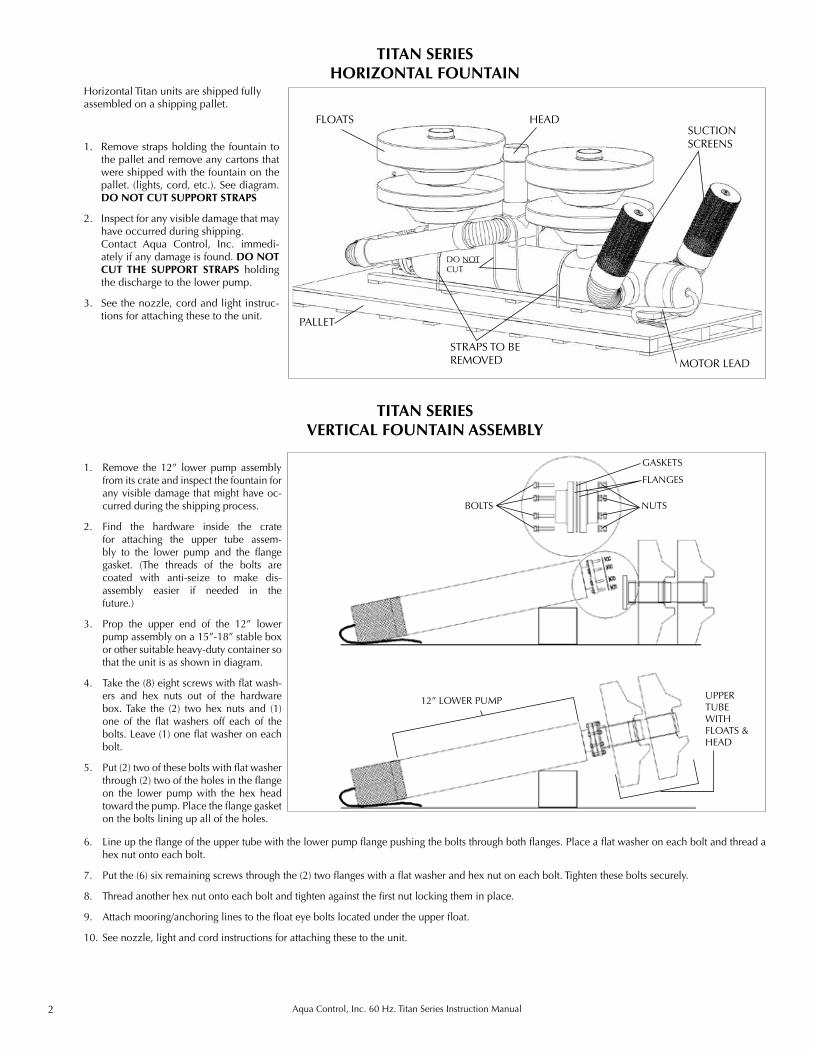
2. Remove the screws with lock washers from the threaded holes in the flat spray plate and the hex head bolts, lock washers, and flat washers from the discharge head spoke.
3. Remove the hardware in the center row of holes in the head using a 5/16” wrench on the cap nut. This hardware will not be reused.
4. Tear open the packet of petroleum jelly and apply it generously to the o-ring on the flange of the flat spray plate. Spread it evenly over the o-ring. Never use the petroleum jelly on the electrical quick disconnects.
5. Line up the threaded holes of the discharge head spoke with the center row of holes in the head. Slide the discharge head spoke inside the head and attach with the hex head bolts, lock washers, and flat washers removed in step #2.
6. Slide the flange of the flat spray plate into the top of the head. Make sure the threaded holes in the flange of the spray cone are lined up with the holes in the top of the head.
7. Reattach the screws with lock washers removed in step #2.
NOZZLES
NOZZLE TYPE 3 – FLAT SPRAY PLATE WITH DISCHARGE HEAD SPOKE
1. Remove the nozzle from its box.
2. Remove the screws with lock washers from the threaded holes in the spray cone and the hex head bolts, lock washers, and flat washers from the discharge head spoke.
3. Remove the hardware in the center row of holes in the head using a 5/16” wrench on the cap nut. This hardware will not be reused.
4. Tear open the packet of petroleum jelly and apply it generously to the o-ring on the flange of the nozzle. Spread it evenly over the o-ring. Never use the petroleum jelly on the electrical quick disconnects.
5. Holding the nozzle by the tip of the threaded rod, line up the threaded holes of the discharge head spoke with the center row of holes in the head. Slide the discharge head spoke inside the head and attach with the hex head bolts, lock washers, and flat washers removed in step #2.
6. Slide the flange of the spray cone into the top of the head. Make sure the threaded holes in the flange of the spray cone are lined up with the holes in the top of the head.
7. Reattach the screws with lock washers removed in step #2.
8. The nozzle has been pre-set at the factory.
NOZZLE TYPE 2 – SPRAY CONE WITH DISCHARGE HEAD SPOKE
NOZZLE TYPE 1 – MULTIPLE NOZZLE CASTING/SPRAY CONE
1. Remove the nozzle from its box.
2. Remove the screws with lock washers from the threaded holes in the nozzle.
3. Tear open the packet of petroleum jelly and apply it generously to the o-ring on the flange of the nozzle. Spread it evenly over the o-ring. Never use the petroleum jelly on the electrical quick disconnects.
4. Slide the flange of the nozzle into the top of the head. Make sure the threaded holes in the flange of the nozzle are lined up with the holes in the top of the head.
4. Reattach the hardware removed in step #2.
NOZZLE
HEAD
LILY PLATE
SPRAY CONEDISCHARGE HEAD SPOKE
HEAD
FLAT SPRAY PLATE
HEAD
DISCHARGE HEADSPOKE
5Aqua Control, Inc. 60 Hz. Titan Series Instruction Manual
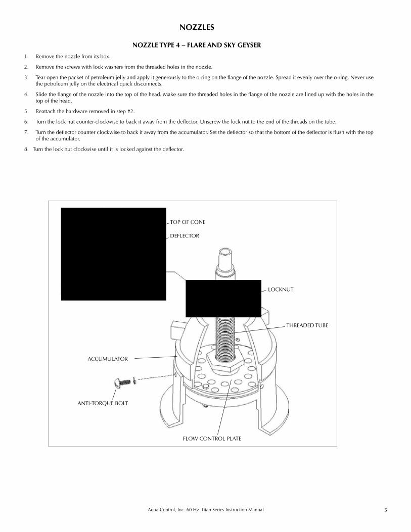
NOZZLE TYPE 4 – FLARE AND SKY GEYSER
NOZZLES
1. Remove the nozzle from its box.
2. Remove the screws with lock washers from the threaded holes in the nozzle.
3. Tear open the packet of petroleum jelly and apply it generously to the o-ring on the flange of the nozzle. Spread it evenly over the o-ring. Never use the petroleum jelly on the electrical quick disconnects.
4. Slide the flange of the nozzle into the top of the head. Make sure the threaded holes in the flange of the nozzle are lined up with the holes in the top of the head.
5. Reattach the hardware removed in step #2.
6. Turn the lock nut counter-clockwise to back it away from the deflector. Unscrew the lock nut to the end of the threads on the tube.
7. Turn the deflector counter clockwise to back it away from the accumulator. Set the deflector so that the bottom of the deflector is flush with the top of the accumulator.
8. Turn the lock nut clockwise until it is locked against the deflector.
LOCKNUT
DEFLECTOR
FLOW CONTROL PLATE
THREADED TUBE
ACCUMULATOR
ANTI-TORQUE BOLT
TOP OF CONE
6 Aqua Control, Inc. 60 Hz. Titan Series Instruction Manual
TITAN SERIES FRESHWATER
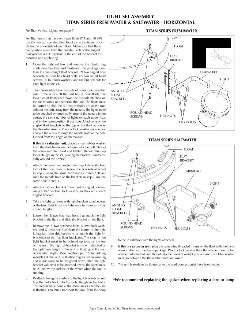
LIGHT SET ASSEMBLYTITAN SERIES FRESHWATER & SALTWATER - HORIZONTAL
For Titan Vertical Lights, see page 7.
For Titan units that have only two floats (7.5 and 10 HP) use (2) two extra angled float brackets in the finger pock-ets on the underside of each float. Make sure that these are pointing away from the nozzle. Each of the angled brackets has a 1/4” eyebolt in the end of the bracket for mooring and anchoring.
1. Open the light set box and remove the plastic bag containing brackets and hardware. The package con-tains (1) one straight float bracket, (2) two angled float brackets, (4) four hex head bolts, (2) two round head screws, (4) four lock washers, and (4) four hex nuts for each light in the set.
2. Titan horizontals have two sets of floats, one on either side of the nozzle. If the unit has (4) four floats, the lower set of floats each have one eyebolt attached on top for mooring or anchoring the unit. The floats must be turned so that the (2) two eyebolts are at the out-sides of the unit, away from the nozzle. The lights need to be attached symmetrically around the nozzle in the center, the same number of lights on each upper float and in the same position if possible. Attach one of the angled float brackets to the top of the float at one of the threaded inserts. Place a lock washer on a screw and put the screw through the middle hole or the hole furthest from the angle on the bracket.
If this is a saltwater unit, place a small rubber washer
from the float hardware package onto the bolt. Thread the screw into the insert and tighten. Repeat this step for each light in the set, placing the brackets symmetri-cally around the nozzle.
3. Attach the remaining angled float brackets to the bot-tom of the float directly below the brackets attached in step 2, using the same hardware as in step 2. If you used the middle hole on the brackets in step 2, use the same hole in step 3.
4. Attach a flat float bracket to each set of angled brackets using a 3/4” hex bolt, lock washer, and hex nut at each angled bracket.
5. Take the light canisters with light brackets attached out of the box. Stretch out the light leads to make sure they are not tangled.
6. Loosen the (2) two hex head bolts that attach the light bracket to the light and slide the bracket off the light.
7. Remove the (2) two hex head bolts, (2) two lock wash-ers, and (2) two hex nuts from the center of the light U-bracket. Use this hardware to attach the light U-bracket(s) to the flat float bracket(s). The slots in the light bracket need to be pointed up towards the top of the unit. The light U-bracket is shown attached at the optimum height if the unit is floating at the rec-ommended depth. (See flotation pg. 16 for adding weights.) If the unit is floating higher when running and is not going to be weighted down, then the light bracket will need to be attached lower. The lights must be 2” below the surface of the water when the unit is running.
8. Reattach the light canisters to the light brackets by set-ting the bolts back into the slots. Retighten the bolts. This step must be done at the shoreline or after the unit is floating. DO NOT transport the unit from the shop
TITAN SERIES SALTWATER
HEX BOLTS
ANGLEDFLOATBRACKETS
U-BRACKET
FLOAT
LIGHT
ROUND HEAD SCREWS HEX NUTS
HEX BOLTS
ROUND HEAD SCREWS HEX NUTS
U-BRACKET
FLOAT
LIGHT
to the installation with the lights attached.
9. If this is a saltwater unit, plug the remaining threaded inserts on the float with the hard-ware in the float hardware package. Place a lock washer then flat washer then rubber washer onto the bolt and thread into the insert. If weight pins are used, a rubber washer must go between the flat washer and float insert.
10. The unit is ready to be floated after the cord connection(s) have been made.
FLATBRACKET
ANGLEDFLOATBRACKETS
FLATBRACKET
*We recommend replacing the gasket when replacing a lens or lamp.
7Aqua Control, Inc. 60 Hz. Titan Series Instruction Manual
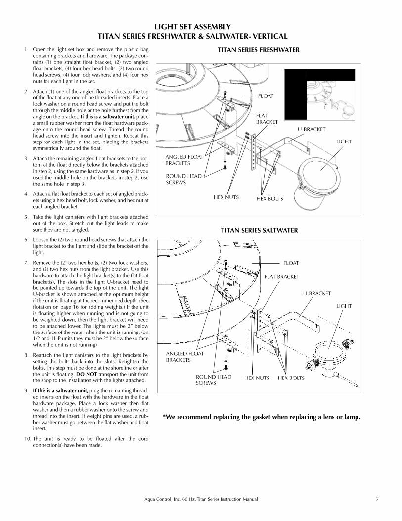
1. Open the light set box and remove the plastic bag containing brackets and hardware. The package con-tains (1) one straight float bracket, (2) two angled float brackets, (4) four hex head bolts, (2) two round head screws, (4) four lock washers, and (4) four hex nuts for each light in the set.
2. Attach (1) one of the angled float brackets to the top of the float at any one of the threaded inserts. Place a lock washer on a round head screw and put the bolt through the middle hole or the hole furthest from the angle on the bracket. If this is a saltwater unit, place a small rubber washer from the float hardware pack-age onto the round head screw. Thread the round head screw into the insert and tighten. Repeat this step for each light in the set, placing the brackets symmetrically around the float.
3. Attach the remaining angled float brackets to the bot-tom of the float directly below the brackets attached in step 2, using the same hardware as in step 2. If you used the middle hole on the brackets in step 2, use the same hole in step 3.
4. Attach a flat float bracket to each set of angled brack-ets using a hex head bolt, lock washer, and hex nut at each angled bracket.
5. Take the light canisters with light brackets attached out of the box. Stretch out the light leads to make sure they are not tangled.
6. Loosen the (2) two round head screws that attach the light bracket to the light and slide the bracket off the light.
7. Remove the (2) two hex bolts, (2) two lock washers, and (2) two hex nuts from the light bracket. Use this hardware to attach the light bracket(s) to the flat float bracket(s). The slots in the light U-bracket need to be pointed up towards the top of the unit. The light U-bracket is shown attached at the optimum height if the unit is floating at the recommended depth. (See flotation on page 16 for adding weights.) If the unit is floating higher when running and is not going to be weighted down, then the light bracket will need to be attached lower. The lights must be 2” below the surface of the water when the unit is running. (on 1/2 and 1HP units they must be 2” below the surface when the unit is not running)
8. Reattach the light canisters to the light brackets by setting the bolts back into the slots. Retighten the bolts. This step must be done at the shoreline or after the unit is floating. DO NOT transport the unit from the shop to the installation with the lights attached.
9. If this is a saltwater unit, plug the remaining thread-ed inserts on the float with the hardware in the float hardware package. Place a lock washer then flat washer and then a rubber washer onto the screw and thread into the insert. If weight pins are used, a rub-ber washer must go between the flat washer and float insert.
10. The unit is ready to be floated after the cord connection(s) have been made.
LIGHT SET ASSEMBLYTITAN SERIES FRESHWATER & SALTWATER- VERTICAL
TITAN SERIES FRESHWATER
TITAN SERIES SALTWATER
U-BRACKET
FLOAT
LIGHT
ROUND HEAD SCREWS
HEX NUTS HEX BOLTS
HEX BOLTS
ANGLED FLOAT BRACKETS
U-BRACKET
FLOAT
LIGHT
ROUND HEAD SCREWS
HEX NUTS
FLAT BRACKET
ANGLED FLOAT BRACKETS
FLAT BRACKET
*We recommend replacing the gasket when replacing a lens or lamp.
8 Aqua Control, Inc. 60 Hz. Titan Series Instruction Manual
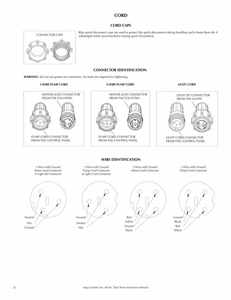
CORD CAPS
3 WIRE PUMP CORD
Blue quick disconnect caps are used to protect the quick disconnects during handling and to keep them dry if submerged while unconnected to mating quick disconnects.
4 WIRE PUMP CORD
CONNECTOR CAPS
CORD
WIRE IDENTIFICATION
2 Wire with Ground Motor Lead Connector & Light Set Connector
2 Wire with Ground Pump Cord Connector
& Light Cord Connector
3 Wire with Ground Motor Lead Connector
3 Wire with Ground Pump Cord Connector
Neutral
Hot
Ground
Ground
Neutral
Hot
RedYellow
GroundBlack
GroundBlack
RedYellow
CONNECTOR IDENTIFICATION
LIGHT CORD
PUMP CORD CONNECTOR FROM THE CONTROL PANEL
MOTOR LEAD CONNECTOR FROM THE FOUNTAIN
PUMP CORD CONNECTOR FROM THE CONTROL PANEL
MOTOR LEAD CONNECTOR FROM THE FOUNTAIN
WARNING: Do not use grease on connectors. No tools are required for tightening.
LIGHT CORD CONNECTOR FROM THE CONTROL PANEL
LIGHT SET CONNECTOR FROM THE LIGHTS
9Aqua Control, Inc. 60 Hz. Titan Series Instruction Manual
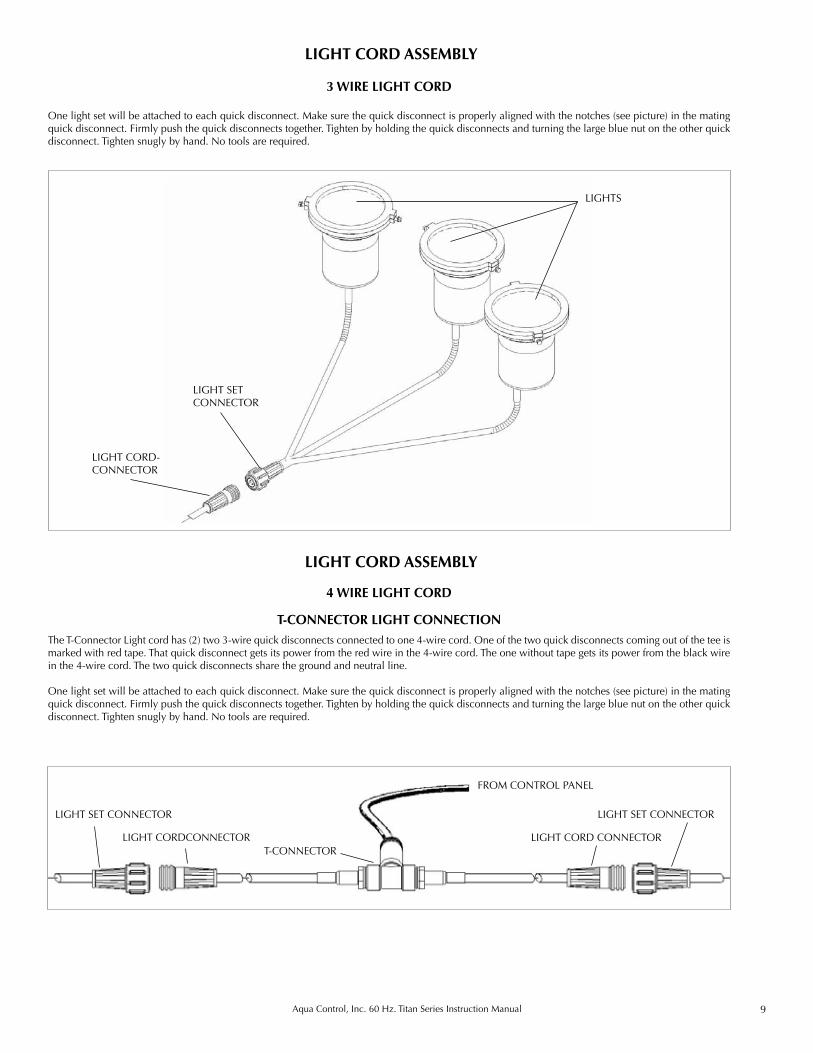
T-CONNECTOR LIGHT CONNECTIONThe T-Connector Light cord has (2) two 3-wire quick disconnects connected to one 4-wire cord. One of the two quick disconnects coming out of the tee is marked with red tape. That quick disconnect gets its power from the red wire in the 4-wire cord. The one without tape gets its power from the black wire in the 4-wire cord. The two quick disconnects share the ground and neutral line.
One light set will be attached to each quick disconnect. Make sure the quick disconnect is properly aligned with the notches (see picture) in the mating quick disconnect. Firmly push the quick disconnects together. Tighten by holding the quick disconnects and turning the large blue nut on the other quick disconnect. Tighten snugly by hand. No tools are required.
FROM CONTROL PANEL
LIGHT SET CONNECTOR
T-CONNECTOR
4 WIRE LIGHT CORD
LIGHT CORD ASSEMBLY
3 WIRE LIGHT CORD
LIGHT CORD ASSEMBLY
One light set will be attached to each quick disconnect. Make sure the quick disconnect is properly aligned with the notches (see picture) in the mating quick disconnect. Firmly push the quick disconnects together. Tighten by holding the quick disconnects and turning the large blue nut on the other quick disconnect. Tighten snugly by hand. No tools are required.
LIGHTS
LIGHT SET CONNECTOR
LIGHT CORD-CONNECTOR
LIGHT CORDCONNECTOR LIGHT CORD CONNECTOR
LIGHT SET CONNECTOR
10 Aqua Control, Inc. 60 Hz. Titan Series Instruction Manual
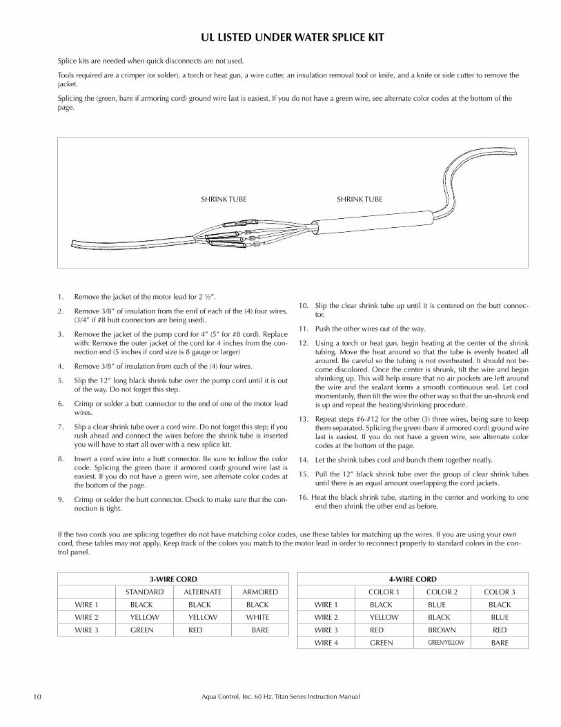
Splice kits are needed when quick disconnects are not used.
Tools required are a crimper (or solder), a torch or heat gun, a wire cutter, an insulation removal tool or knife, and a knife or side cutter to remove the jacket.
Splicing the (green, bare if armoring cord) ground wire last is easiest. If you do not have a green wire, see alternate color codes at the bottom of the page.
UL LISTED UNDER WATER SPLICE KIT
1. Remove the jacket of the motor lead for 2 ½”.
2. Remove 3/8” of insulation from the end of each of the (4) four wires, (3/4” if #8 butt connectors are being used).
3. Remove the jacket of the pump cord for 4” (5” for #8 cord). Replace with: Remove the outer jacket of the cord for 4 inches from the con-nection end (5 inches if cord size is 8 gauge or larger)
4. Remove 3/8” of insulation from each of the (4) four wires.
5. Slip the 12” long black shrink tube over the pump cord until it is out of the way. Do not forget this step.
6. Crimp or solder a butt connector to the end of one of the motor lead wires.
7. Slip a clear shrink tube over a cord wire. Do not forget this step; if you rush ahead and connect the wires before the shrink tube is inserted you will have to start all over with a new splice kit.
8. Insert a cord wire into a butt connector. Be sure to follow the color code. Splicing the green (bare if armored cord) ground wire last is easiest. If you do not have a green wire, see alternate color codes at the bottom of the page.
9. Crimp or solder the butt connector. Check to make sure that the con-nection is tight.
10. Slip the clear shrink tube up until it is centered on the butt connec-tor.
11. Push the other wires out of the way.
12. Using a torch or heat gun, begin heating at the center of the shrink tubing. Move the heat around so that the tube is evenly heated all around. Be careful so the tubing is not overheated. It should not be-come discolored. Once the center is shrunk, tilt the wire and begin shrinking up. This will help insure that no air pockets are left around the wire and the sealant forms a smooth continuous seal. Let cool momentarily, then tilt the wire the other way so that the un-shrunk end is up and repeat the heating/shrinking procedure.
13. Repeat steps #6-#12 for the other (3) three wires, being sure to keep them separated. Splicing the green (bare if armored cord) ground wire last is easiest. If you do not have a green wire, see alternate color codes at the bottom of the page.
14. Let the shrink tubes cool and bunch them together neatly.
15. Pull the 12” black shrink tube over the group of clear shrink tubes until there is an equal amount overlapping the cord jackets.
16. Heat the black shrink tube, starting in the center and working to one end then shrink the other end as before.
SHRINK TUBESHRINK TUBE
If the two cords you are splicing together do not have matching color codes, use these tables for matching up the wires. If you are using your own cord, these tables may not apply. Keep track of the colors you match to the motor lead in order to reconnect properly to standard colors in the con-trol panel.
4-WIRE CORD
COLOR 1 COLOR 2 COLOR 3
WIRE 1 BLACK BLUE BLACK
WIRE 2 YELLOW BLACK BLUE
WIRE 3 RED BROWN RED
WIRE 4 GREEN GREEN/YELLOW BARE
3-WIRE CORD
STANDARD ALTERNATE ARMORED
WIRE 1 BLACK BLACK BLACK
WIRE 2 YELLOW YELLOW WHITE
WIRE 3 GREEN RED BARE
11Aqua Control, Inc. 60 Hz. Titan Series Instruction Manual
INSTALLATION
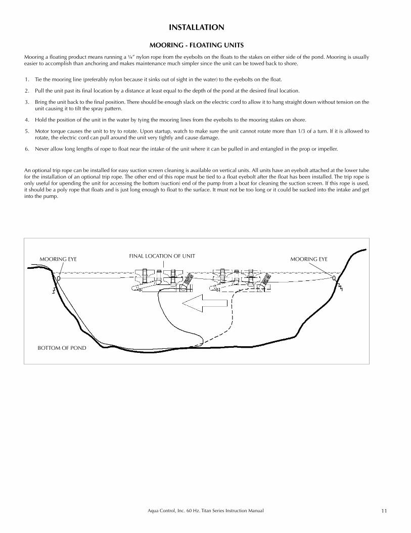
1. Tie the mooring line (preferably nylon because it sinks out of sight in the water) to the eyebolts on the float.
2. Pull the unit past its final location by a distance at least equal to the depth of the pond at the desired final location.
3. Bring the unit back to the final position. There should be enough slack on the electric cord to allow it to hang straight down without tension on the unit causing it to tilt the spray pattern.
4. Hold the position of the unit in the water by tying the mooring lines from the eyebolts to the mooring stakes on shore.
5. Motor torque causes the unit to try to rotate. Upon startup, watch to make sure the unit cannot rotate more than 1/3 of a turn. If it is allowed to rotate, the electric cord can pull around the unit very tightly and cause damage.
6. Never allow long lengths of rope to float near the intake of the unit where it can be pulled in and entangled in the prop or impeller.
Mooring a floating product means running a ¼” nylon rope from the eyebolts on the floats to the stakes on either side of the pond. Mooring is usually easier to accomplish than anchoring and makes maintenance much simpler since the unit can be towed back to shore.
MOORING - FLOATING UNITS
An optional trip rope can be installed for easy suction screen cleaning is available on vertical units. All units have an eyebolt attached at the lower tube for the installation of an optional trip rope. The other end of this rope must be tied to a float eyebolt after the float has been installed. The trip rope is only useful for upending the unit for accessing the bottom (suction) end of the pump from a boat for cleaning the suction screen. If this rope is used, it should be a poly rope that floats and is just long enough to float to the surface. It must not be too long or it could be sucked into the intake and get into the pump.
MOORING EYE
BOTTOM OF POND
MOORING EYEFINAL LOCATION OF UNIT
12 Aqua Control, Inc. 60 Hz. Titan Series Instruction Manual
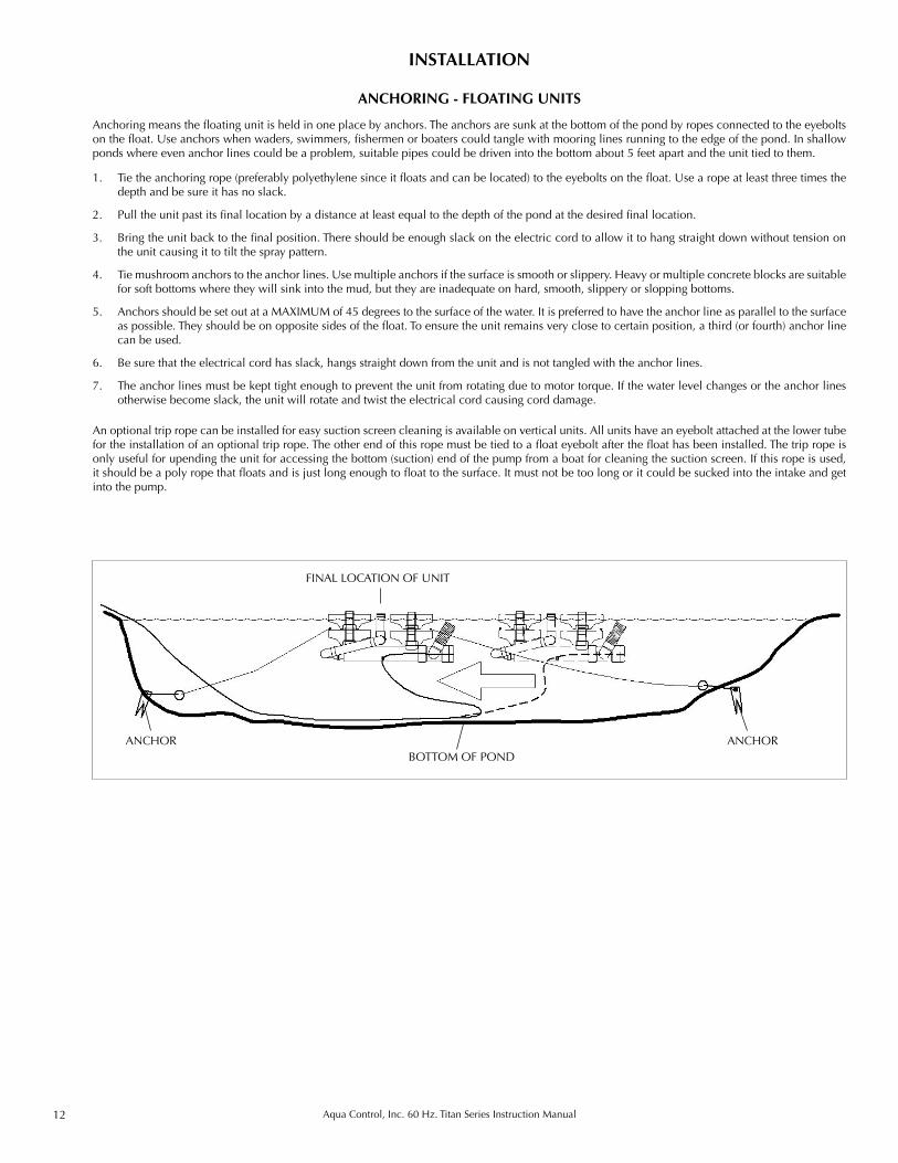
1. Tie the anchoring rope (preferably polyethylene since it floats and can be located) to the eyebolts on the float. Use a rope at least three times the depth and be sure it has no slack.
2. Pull the unit past its final location by a distance at least equal to the depth of the pond at the desired final location.
3. Bring the unit back to the final position. There should be enough slack on the electric cord to allow it to hang straight down without tension on the unit causing it to tilt the spray pattern.
4. Tie mushroom anchors to the anchor lines. Use multiple anchors if the surface is smooth or slippery. Heavy or multiple concrete blocks are suitable for soft bottoms where they will sink into the mud, but they are inadequate on hard, smooth, slippery or slopping bottoms.
5. Anchors should be set out at a MAXIMUM of 45 degrees to the surface of the water. It is preferred to have the anchor line as parallel to the surface as possible. They should be on opposite sides of the float. To ensure the unit remains very close to certain position, a third (or fourth) anchor line can be used.
6. Be sure that the electrical cord has slack, hangs straight down from the unit and is not tangled with the anchor lines.
7. The anchor lines must be kept tight enough to prevent the unit from rotating due to motor torque. If the water level changes or the anchor lines otherwise become slack, the unit will rotate and twist the electrical cord causing cord damage.
Anchoring means the floating unit is held in one place by anchors. The anchors are sunk at the bottom of the pond by ropes connected to the eyebolts on the float. Use anchors when waders, swimmers, fishermen or boaters could tangle with mooring lines running to the edge of the pond. In shallow ponds where even anchor lines could be a problem, suitable pipes could be driven into the bottom about 5 feet apart and the unit tied to them.
ANCHORING - FLOATING UNITS
INSTALLATION
An optional trip rope can be installed for easy suction screen cleaning is available on vertical units. All units have an eyebolt attached at the lower tube for the installation of an optional trip rope. The other end of this rope must be tied to a float eyebolt after the float has been installed. The trip rope is only useful for upending the unit for accessing the bottom (suction) end of the pump from a boat for cleaning the suction screen. If this rope is used, it should be a poly rope that floats and is just long enough to float to the surface. It must not be too long or it could be sucked into the intake and get into the pump.
BOTTOM OF PONDANCHOR ANCHOR
FINAL LOCATION OF UNIT
13Aqua Control, Inc. 60 Hz. Titan Series Instruction Manual
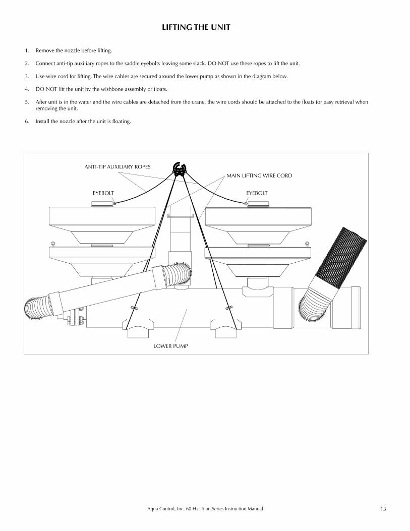
LIFTING THE UNIT
1. Remove the nozzle before lifting.
2. Connect anti-tip auxiliary ropes to the saddle eyebolts leaving some slack. DO NOT use these ropes to lift the unit.
3. Use wire cord for lifting. The wire cables are secured around the lower pump as shown in the diagram below.
4. DO NOT lift the unit by the wishbone assembly or floats.
5. After unit is in the water and the wire cables are detached from the crane, the wire cords should be attached to the floats for easy retrieval when removing the unit.
6. Install the nozzle after the unit is floating.
EYEBOLT
MAIN LIFTING WIRE CORD
LOWER PUMP
ANTI-TIP AUXILIARY ROPES
EYEBOLT
14 Aqua Control, Inc. 60 Hz. Titan Series Instruction Manual
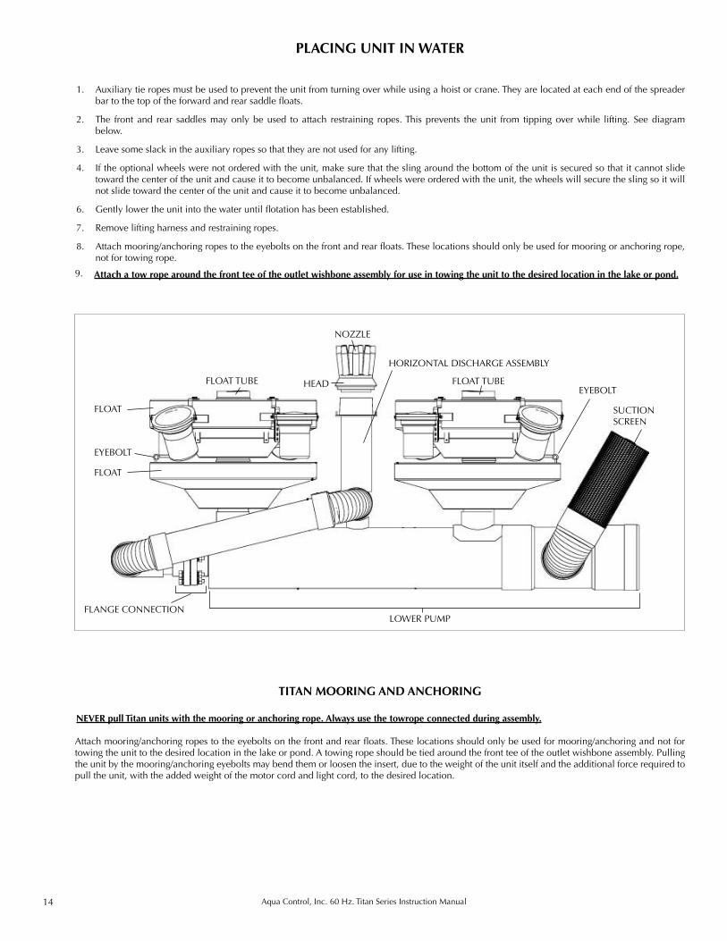
PLACING UNIT IN WATER
1. Auxiliary tie ropes must be used to prevent the unit from turning over while using a hoist or crane. They are located at each end of the spreader bar to the top of the forward and rear saddle floats.
2. The front and rear saddles may only be used to attach restraining ropes. This prevents the unit from tipping over while lifting. See diagram below.
3. Leave some slack in the auxiliary ropes so that they are not used for any lifting.
4. If the optional wheels were not ordered with the unit, make sure that the sling around the bottom of the unit is secured so that it cannot slide toward the center of the unit and cause it to become unbalanced. If wheels were ordered with the unit, the wheels will secure the sling so it will not slide toward the center of the unit and cause it to become unbalanced.
6. Gently lower the unit into the water until flotation has been established.
7. Remove lifting harness and restraining ropes.
8. Attach mooring/anchoring ropes to the eyebolts on the front and rear floats. These locations should only be used for mooring or anchoring rope, not for towing rope.
NEVER pull Titan units with the mooring or anchoring rope. Always use the towrope connected during assembly.
Attach mooring/anchoring ropes to the eyebolts on the front and rear floats. These locations should only be used for mooring/anchoring and not for towing the unit to the desired location in the lake or pond. A towing rope should be tied around the front tee of the outlet wishbone assembly. Pulling the unit by the mooring/anchoring eyebolts may bend them or loosen the insert, due to the weight of the unit itself and the additional force required to pull the unit, with the added weight of the motor cord and light cord, to the desired location.
TITAN MOORING AND ANCHORING
NOZZLE
SUCTION SCREEN
FLOAT
FLOAT
LOWER PUMP
HORIZONTAL DISCHARGE ASSEMBLY
HEAD
FLANGE CONNECTION
EYEBOLT
EYEBOLTFLOAT TUBE FLOAT TUBE
Attach a tow rope around the front tee of the outlet wishbone assembly for use in towing the unit to the desired location in the lake or pond.9.
15Aqua Control, Inc. 60 Hz. Titan Series Instruction Manual
Aqua Control Inc. (ACI) is certified to manufacture UL Listed Industrial Control Panels (UL 508A), and all control panels are UL listed except 460V panels or panels built with prior agreement for certain special configurations. Certain special configurations, the 1hp-115V, all 460V and all 575V control panels cannot be UL Listed because of the National Electric Code and UL requirements.
INSTALLER QUALIFICATIONS ACI control panels must be installed by a QUALIFIED electrician who will read and understand the instructions and knows electrical installation to your local and state codes. Do not install this control panel if you are not qualified. Only a qualified electrician can safely make this installation. If you do not understand the instructions and you are not qualified to make electrical installations, it is NOT SAFE for an unqualified person to be making this instal-lation. A complete set of instructions, which is specific to each control panel, are shipped inside each control panel. Refer to those instructions for each specific component’s operation instructions. Control panel schematics are also included in all control panels.
LOCATION OF CONTROL PANELS
Control panels should always be installed in a manner that minimizes heat inside the panel since the panels generate some heat and they contain heat sensitive components (motor overloads). Sunlight is the most significant source of heat, so the control panels should be installed out of direct sun as much as possible. The door of the control panel, particularly, should not face south or west unless it is protected from sunlight.
1. Install the control panel facing north and with the back covered to minimize heating from the sun.2. Install a sunroof over the control panel and leave an air gap of at least 2 inches. The roof should shade the control panel from mid morning until late afternoon to minimize heating from the sun.3. Install on a wall so that the control panel faces north or east.4. Install in a building so that direct sunshine will not heat the control panel.5. Control panels with Variable Frequency Drives (VFD) MUST be protected from sunlight since the drive creates a substantial additional heat load. Fans and vents are included in all panels that contain VFDs.
SUPPLY CORD (INCOMING POWER) The supply cord from the power supply to the control panel must be sized for a power supply voltage drop of no more than 3%. All output cord sizing is based on a maximum of 5% voltage drop, so the supply cord voltage drop of 3% must not be exceeded.
NUMBER OF REQUIRED SUPPLY CORD CONDUCTORS WARNING: It is the installer’s responsibility to provide and connect a neutral wire to the neutral input terminal block. Failure to connect a neutral wire will burn out the GFCI-Circuit Breakers. GFCI-Circuit Breakers that fail during installation are NOT COVERED UNDER WARRANTY.
1. Single phase, 120V power supply should be 3 wires: 1 hot, 1 neutral, and a ground.
2. Single phase, 208/230V 60 Hz power supply should be 4 wires: 2 hots, 1 neutral, and a ground. Both hots must be 120V to neutral.
3. Three phase, 208 or 230V, 60 Hz power should be 5 wires: 3 hots, 1 neutral and a ground.
4. Three phase, 460/480V 60 Hz should be 4 wires: 3 hots and a ground. A. If no external source of 120V is to be supplied, the required 120V for the only control circuit can be supplied from an optional internal
control transformer. B. If an external source of 120V is supplied for the control circuit and/or lights, 120V supply power must also be supplied along with the
460/480V. (6 wires total) C. If an external source of 120/240V is supplied for the control circuit and for 2 or more sets of lights, 120/240V power, (2 hots with 240V
between them and each 120V to neutral) must be supplied. (7 wires total)
START UP
At installation and initial start up, it is recommended to record the actual voltage under load (while the unit is running) and the running amperage of the unit. This can be kept inside the control panel for future reference. This allows for easy determination if something at site or with the installation has changed. The correct voltage and amperage ratings are on the schematic and on the door label of the control panel.
CONTROL PANELSINSTALLATION
16 Aqua Control, Inc. 60 Hz. Titan Series Instruction Manual
CONTROL PANELSINSTALLATION
Any Aqua Control, Inc. Fountain can be operated continuously or intermittently as desired except during freezing weather. If a less than normal flow is observed, it is imperative that the cause be promptly investigated and corrected. Failure to do so can cause cavitation resulting in pump and motor damage and will void the warranty. Reduced flow will usually be due to a blockage that must be removed.
MODIFICATION OF THE CONTROL PANEL
UL RATING
Field modifications to the control panel made by anyone not qualified and authorized by UL to make such modifications, or modified with non-UL rated components, will render the control panel no longer UL Listed.
ACI WARRANTY
Modification of the Control Panel will void the Aqua Control warranty on the entire unit unless Aqua Control specifically approves the changes.
ADDING VENTILATION
If ventilation is added in the field, it must be done with a NEMA 3R rated and screened (or filtered) ventilation kit. A screened ventilation hole or holes can be put in the bottom of the enclosure.
FLOTATION
TITAN SERIES
1. Bar weights can be added to level the unit, sink lights below the water surface, or to make the floats less visible during operation.
2. Each large bar weighs ten (10) lbs. in the water and the smaller bar weighs five (5) lbs. The weights should be placed inside the vertical saddle tubes at either the front or rear floats until the unit is at the desired depth and floating level.
3. The front and rear floats should have an equal amount exposed above the water at the front and rear saddles.
4. Each inch of float depth showing while the unit is running requires 33 lbs to sink. (Because there are two floats, it requires 66 lbs. of evenly dis-tributed weight to sink the unit one inch.)
5. After the unit is leveled, additional weights can be added in the front and rear saddle tubes to sink the unit further, if necessary.
6. Lights need to be completely submerged when the unit is operating.
17Aqua Control, Inc. 60 Hz. Titan Series Instruction Manual
1. Disconnect the motor from the cord or cut the cord at the splice.
2. Store in a heated area that will not freeze.
3. Store with the shaft end of the motor inclined up. If a vertical unit is resting on the float and on the bottom of the lower tube. The angle will be satisfactory. Do not rest it on the lights or light brackets.
4. The underwater cord should not be left on the ground since it could easily be damaged when brittle from cold weather. Re-immerse the cord so it is out of the ice and away from shore traffic.
5. Protect the cord connector in the water by using the cap that came with the unit.
REMOVAL
If the surface of the pond does not normally freeze solid then continued winter operation of either aerators or fountains is seldom a problem.
1. During a cold snap, it may be necessary to shut the unit off to prevent ice accumulation on the float, which could cause the unit to tip. If the unit tips and has lights, some of the lights could come out of the water, possibly allowing them to break or leak from overheating. It might also allow the gasket to freeze and water could leak into the fixture.
2. To be certain that operation with a nozzle does not create a large mound of ice which could cause the aerator to roll over and result in motor or light damage, simply remove the nozzle and let the water gush out to provide circulation of the warmer deep water up to the surface.
3. Do not remove the head or the unit will slip through the float and sink to the bottom.
FREEZING WEATHER
WINTER OPERATION
SAFETY ADVISORY! If winter activities occur on the lake, operation of a unit during the winter will compromise the thickness and stability of the ice that develops around the perimeter of the open water and could create a safety hazard for anyone on the ice.
WARRANTY DISCLAIMER: Many variables must be considered before deciding to operate a Titan Fountain during the winter. These variables include but are not limited to the depth of the lake, overall size of the lake, climate variation, predictability of cold, and loss of power in winter conditions. Aqua Control does not warrant any damage incurred during winter operation, even if the following guidelines are followed.
MARGINALLY FREEZING WEATHER
MAINTENANCE
The Aqua Control products do not require yearly maintenance of the motors or pumps. The motors should never be opened for maintenance and doing so will void the factory warranty.
SUCTION SCREEN CLEANING: Routine cleaning of the suction screen is required to assure adequate water flow past the motor to cool it during opera-tion. If the screen becomes fouled with debris the motor can overheat and the spray pattern can be diminished. The mooring and anchoring installation instructions suggest a trip rope for the vertical units so the suction screen can be lifted to the surface of the water for cleaning. The suction screens on the horizontal units are close to the water’s surface to make them easy to reach. A wire brush can be used to remove any debris.
LIGHT LENS CLEANING: The light lenses should be cleaned frequently to prevent algae and dirt buildup on them. Buildup dims the amount of light that comes through the lenses and can cause them to overheat as well. If rock guards are used on the lights, the lights should be monitored more fre-quently for algae buildup.
18 Aqua Control, Inc. 60 Hz. Titan Series Instruction Manual
1. Set Up the Multimeter
a. Ohms i. Know the range of Ohms available for your multimeter and whether your meter is auto-ranging. ii. Set the multimeter to the lowest Ohm (resistance) setting. Resistance is designated by Ohms. iii. Determine how your multimeter designates open line. Observe the reading when both probes are held in the air, not
touching. iv. Determine how your multimeter designates continuity. This is done by touching the two probes. This should be
either zero or very close to zero. If not zero, this may be resistance internal to the meter and should be subtracted from all subsequent readings. If your meter has an “auto-zero” feature, use it to zero the meter.
b. Volts i. Set the multimeter to the highest setting ii. Select AC volts. This is usually designated by VAC. c. Amps - Use only a clamp ammeter e.g. Amprobe.
2. Check Neutral to Ground Voltage
a. Set multimeter to AC voltage, highest rating. b. Check the voltage between Neutral and Ground. c. The voltage should be zero. d. If the voltage is other than zero, the neutral line may be bad. e. A bad neutral may lead to faulty GFCI tripping.
3. Check Input Voltages - readings should be within 10% of nominal voltage. a. Single Phase i. Each line to Neutral should be approximately ½ of the input voltage. ii. Each line to one another should be the source voltage. b. Three Phase i. 208 volt, Y 1. Each line to Neutral should be 120 volts. 2. Each line to one another should be source voltage. ii. volt, Delta 1. L1 and L3 to Neutral should be half source voltage. 2. L2 to Neutral should be substantially higher. This must be the wild leg connection. iii. volt / 480 volt grounded. 1. Each line to Neutral should be approximately 277 volts. 2. Each line to one another should be source voltage. iv. 480 volt Delta 1. Each line to one another should be source voltage. c. Analysis i. If lines read good to Neutral but zero to one another, the same leg is used for both lines. Correct this at the source. ii. If the lines read bad to one another or bad to Neutral, the power source or power cord must be corrected iii. A three-phase 240 volt delta power source must have the wild leg connected to L2, the center input of the disconnect
switch.
4. Check Output Voltages
a. 2-Wire: T1 - T2 b. 1-Phase: Black - Yellow c. 3-Phase: T1 – T2, T1 – T3, T2 – T3 d. Analysis i. Each reading should give source voltage. ii. If good, problem is not in control panel although overloads or GFCIs may be too sensitive and cause premature tripping. iii. If zero voltage: backtrack through components, checking input vs. output voltages, to determine which one is tripped or
faulty. iv. If low voltage: very unlikely, control panel wired incorrectly.
5. Check Amps – readings should be within 10% of nominal voltage. a. Single phase – check yellow wire. b. Three phase – check each hot wire; readings should be within 5% of one another.
6. If GFCI tripped, perform “GFCI Troubleshooting Procedures”
7. If overload tripped, perform “Overload Troubleshooting Procedures”
TROUBLESHOOTING
GENERAL TROUBLESHOOTING
19Aqua Control, Inc. 60 Hz. Titan Series Instruction Manual
GENERAL TROUBLESHOOTING
Two problems affect cord integrity, shorted lines and broken or open lines. The following procedures will determine cord integrity. The cord should be disconnected from both the motor and the control panel. Verify the power is off before removing the cord.
1. Set up the multimeter
a. Set the multimeter to the lowest Ohm (resistance) setting. Resistance is designated by Ohms. b. Determine how your multimeter designates open line. This is done by observing the reading when both probes are held in the
air, not touching. c. Determine how your multimeter designates continuity. This is done by touching the two probes. This should be either zero or
very close to zero. If not zero, this may be resistance internal to the meter and should be subtracted from all subsequent readings.
2. Disconnect the cord from the control panel and the load (pump or lights). Both ends must be dry. Verify the power is off before removing the cord.
3. Check for shorted lines. A short is an unintentional electrical path and can be caused by faulty insulation.
a. Set the multimeter to the highest Ohm (resistance) setting. b. Take readings by touching the probes to each pair of wires; e.g. red-black, red-yellow, black-yellow, etc. c. Analyze the readings. i. The readings should be the same as the open line readings you observed in step 1b. ii. If the readings designate continuity by giving a zero reading or any reading less than open line, a short exists. iii. If any of the readings with green (ground) indicate continuity, a leak to ground exists. d. Determine the action to take i. Visually inspect the cord. ii. Any manual connection sites are candidates for inspection, e.g. junction boxes, splices. iii. It may be impossible to determine the location of the short and a new cord may be the best solution.
4. Check for open lines. An open line is a break in a wire. a. Set the multimeter to the lowest Ohm (resistance) setting. b. At the control panel, with the cord disconnected from the control panel, join two wires, e.g. red and yellow, by wrapping the
ends together. If you have four wires, you may wish to connect the other two together. Note which wires are connected. c. From the other end of the cord select one of the pairs of joined wires and take readings by touching the probes to each wire
or socket of the quick disconnect. d. Analyze the readings. i. The readings should indicate continuity, (either zero or close to zero). The readings should not exceed a few
Ohms. ii. If the readings indicate either open line or a very high number, a break or partial break exists. iii. If a break exists, one or both of the wires tested may be involved. iv. Determine the action to take. 1. Visually inspect the cord. 2. Any manual connection sites are candidates for inspection, e.g. junction boxes, splices. 3. It may be impossible to determine the location of the open line and a new cord may be the best
solution. e. Perform these steps for each combination of wire pairs.
CORD TROUBLESHOOTING
20 Aqua Control, Inc. 60 Hz. Titan Series Instruction Manual
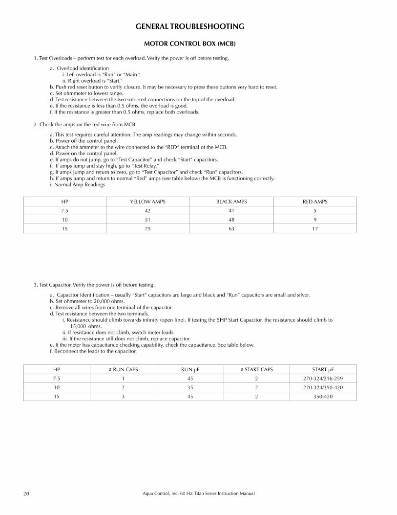
HP YELLOW AMPS BLACK AMPS RED AMPS
7.5 42 41 5
10 51 48 9
15 75 63 17
HP # RUN CAPS RUN µF # START CAPS START µF
7.5 1 45 2 270-324/216-259
10 2 35 2 270-324/350-420
15 3 45 2 350-420
GENERAL TROUBLESHOOTING
1. Test Overloads – perform test for each overload. Verify the power is off before testing.
a. Overload identification i. Left overload is “Run” or “Main.” ii. Right overload is “Start.” b. Push red reset button to verify closure. It may be necessary to press these buttons very hard to reset. c. Set ohmmeter to lowest range. d. Test resistance between the two soldered connections on the top of the overload. e. If the resistance is less than 0.5 ohms, the overload is good. f. If the resistance is greater than 0.5 ohms, replace both overloads.
2. Check the amps on the red wire from MCB.
a. This test requires careful attention. The amp readings may change within seconds. b. Power off the control panel. c. Attach the ammeter to the wire connected to the “RED” terminal of the MCB. d. Power on the control panel. e. If amps do not jump, go to “Test Capacitor” and check “Start” capacitors. f. If amps jump and stay high, go to “Test Relay.” g. If amps jump and return to zero, go to “Test Capacitor” and check “Run” capacitors. h. If amps jump and return to normal “Red” amps (see table below) the MCB is functioning correctly. i. Normal Amp Readings
MOTOR CONTROL BOX (MCB)
3. Test Capacitor. Verify the power is off before testing.
a. Capacitor Identification – usually “Start” capacitors are large and black and “Run” capacitors are small and silver. b. Set ohmmeter to 20,000 ohms. c. Remove all wires from one terminal of the capacitor. d. Test resistance between the two terminals. i. Resistance should climb towards infinity (open line). If testing the 5HP Start Capacitor, the resistance should climb to
15,000 ohms. ii. If resistance does not climb, switch meter leads. iii. If the resistance still does not climb, replace capacitor. e. If the meter has capacitance checking capability, check the capacitance. See table below. f. Reconnect the leads to the capacitor.
21Aqua Control, Inc. 60 Hz. Titan Series Instruction Manual
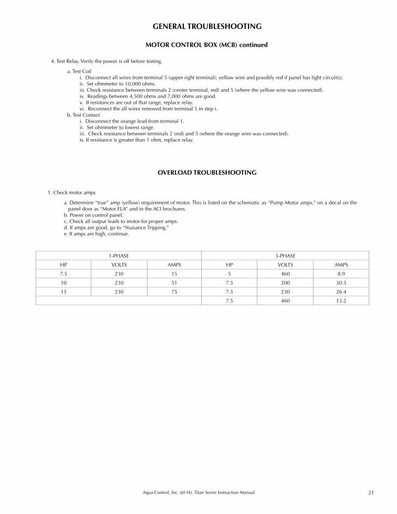
1. Check motor amps
a. Determine “true” amp (yellow) requirement of motor. This is listed on the schematic as “Pump Motor amps,” on a decal on the panel door as “Motor FLA” and in the ACI brochures.
b. Power on control panel. c. Check all output leads to motor for proper amps. d. If amps are good, go to “Nuisance Tripping.” e. If amps are high, continue.
GENERAL TROUBLESHOOTING
OVERLOAD TROUBLESHOOTING
4. Test Relay. Verify the power is off before testing.
a. Test Coil i. Disconnect all wires from terminal 5 (upper right terminal); yellow wire and possibly red if panel has light circuit(s). ii. Set ohmmeter to 10,000 ohms. iii. Check resistance between terminals 2 (center terminal, red) and 5 (where the yellow wire was connected). iv. Readings between 4,500 ohms and 7,000 ohms are good. v. If resistances are out of that range, replace relay. vi. Reconnect the all wires removed from terminal 5 in step i. b. Test Contact i. Disconnect the orange lead from terminal 1. ii. Set ohmmeter to lowest range. iii. Check resistance between terminals 2 (red) and 5 (where the orange wire was connected). iv. If resistance is greater than 1 ohm, replace relay.
1-PHASE 3-PHASE
HP VOLTS AMPS HP VOLTS AMPS
7.5 230 15 5 460 8.9
10 230 51 7.5 200 30.5
15 230 75 7.5 230 26.4
7.5 460 13.2
MOTOR CONTROL BOX (MCB) continued
22 Aqua Control, Inc. 60 Hz. Titan Series Instruction Manual
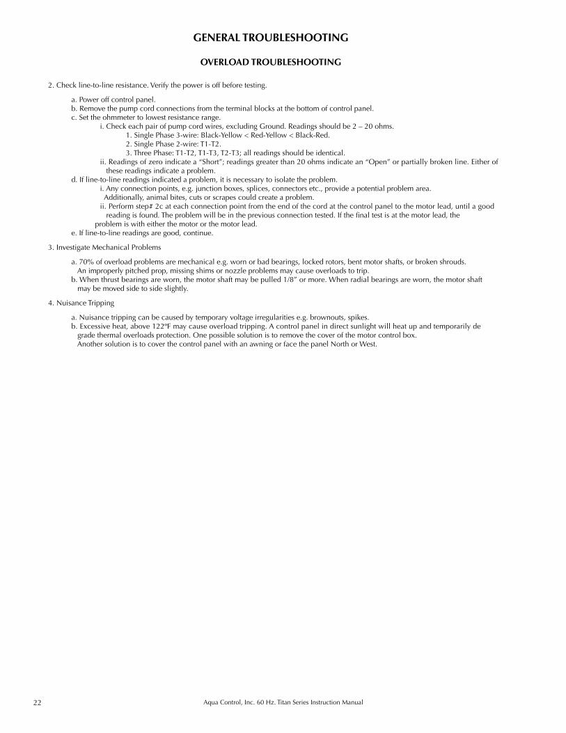
2. Check line-to-line resistance. Verify the power is off before testing.
a. Power off control panel. b. Remove the pump cord connections from the terminal blocks at the bottom of control panel. c. Set the ohmmeter to lowest resistance range. i. Check each pair of pump cord wires, excluding Ground. Readings should be 2 – 20 ohms. 1. Single Phase 3-wire: Black-Yellow < Red-Yellow < Black-Red. 2. Single Phase 2-wire: T1-T2. 3. Three Phase: T1-T2, T1-T3, T2-T3; all readings should be identical. ii. Readings of zero indicate a “Short”; readings greater than 20 ohms indicate an “Open” or partially broken line. Either of
these readings indicate a problem. d. If line-to-line readings indicated a problem, it is necessary to isolate the problem. i. Any connection points, e.g. junction boxes, splices, connectors etc., provide a potential problem area. Additionally, animal bites, cuts or scrapes could create a problem. ii. Perform step# 2c at each connection point from the end of the cord at the control panel to the motor lead, until a good
reading is found. The problem will be in the previous connection tested. If the final test is at the motor lead, the problem is with either the motor or the motor lead.
e. If line-to-line readings are good, continue.
3. Investigate Mechanical Problems
a. 70% of overload problems are mechanical e.g. worn or bad bearings, locked rotors, bent motor shafts, or broken shrouds. An improperly pitched prop, missing shims or nozzle problems may cause overloads to trip. b. When thrust bearings are worn, the motor shaft may be pulled 1/8” or more. When radial bearings are worn, the motor shaft
may be moved side to side slightly.
4. Nuisance Tripping
a. Nuisance tripping can be caused by temporary voltage irregularities e.g. brownouts, spikes. b. Excessive heat, above 122ºF may cause overload tripping. A control panel in direct sunlight will heat up and temporarily de
grade thermal overloads protection. One possible solution is to remove the cover of the motor control box. Another solution is to cover the control panel with an awning or face the panel North or West.
GENERAL TROUBLESHOOTING
OVERLOAD TROUBLESHOOTING