Embed Size (px)
Citation preview
IMPORTANT SAFETY INSTRUCTIONSREAD AND FOLLOW ALL INSTRUCTIONS
SAVE THESE INSTRUCTIONS
Aqua-Clear™
Fiberglass Sand Filters
Installation & User's Guide
Aqua-Clear
© 2011 The Toro Company, Inc. All rights reserved.
This document is subject to change without notice.
1588 N. Marshall Ave., El Cajon, CA 92020 (800) 333-8125 or (619) 562-2950
Aqua-Clear™ and the Toro® logo is a trademark and/or a registered trademark of The Toro Company and/or its affiliated companies in the UnitedStates and/or other counties. Unless noted, names and brands of others that may be used in this document are not used to indicate an affiliation orendorsement between the proprietors of these names and brands. Those names and brands may be the trademarks or registered trademarks ofthose parties or others.
P/N 151002 Rev. A 02/25/11
Customer ServiceIf you have questions about ordering replacement parts, please use the following contactinformation:
Customer Service / Technical Support (8 A.M. to 4:30 P.M. — Eastern and Pacific Times)
Phone: (800) 333-8125 or (619) 562-2950
Fax: (800) 892-1822 or (619) 258-9973
Web site
visit www.toromicroirrigation.com or www.toro.com
i
Aqua-Clear™ Fiberglass Sand Filter Installation and User’s Guide
Table of Contents
Important Warning and Safety Instructions ......................................................................... ii
Section 1: Introduction .....................................................................................................1
Aqua-Clear Fiberglass Sand Filters Overview ........................................................1
General Features..................................................................................................... 1
Additional Features ..................................................................................................1
Section 2: Installation .......................................................................................................2
Installing the AquaClear Fiberglass Sand Filter .......................................................2
Introduction .......................................................................................................... 2
How the Filter Works ...........................................................................................2
Installing the Filter .................................................................................................... 4
Construction of the Manifold System ....................................................................... 5
How to Configure a 3-Way Valve .........................................................................5
Initial Start-Up .......................................................................................................... 6
Section 3: Maintenance ..................................................................................................... 7
Filter Care ................................................................................................................ 7
Cleaning...................................................................................................................7
Filter Procedure .......................................................................................................7
Backwash Procedure .............................................................................................. 8
Winterizing and Storing the Filter ............................................................................. 8
Section 4: Troubleshooting ..............................................................................................9
Section 5: Replacement Parts .......................................................................................... 11
ii
Aqua-Clear™ Fiberglass Sand Filter Installation and User’s Guide
Consumer Information and SafetyThe Aqua-Clear Fiberglass Sand Filters are designed and manufactured to provide many years of safe and reliableservice when installed, operated and maintained according to the information in this manual and the installation codesreferred to in later sections. Throughout the manual, safety warnings and cautions are identified by the symbol. Besure to read and comply with all of the warnings and cautions.
WARNING — THIS FILTER OPERATES UNDER HIGH PRESSURE
When any part of the irrigation system, (e.g., closure, pump, filter, valve(s), etc.), is serviced, aircan enter the system and become pressurized. Pressurized air can cause the top closure toseparate which can result in severe injury, death, or property damage. To avoid this potentialhazard, follow these instructions:
1. If you are not familiar with your irrigation system filtering system:
a. Do NOT attempt to adjust or service without consulting your dealer, or a qualified irrigationsystem technician.
b. Read the entire Installation & User’s Guide before attempting to use, service or adjust thefiltering system.
2. Before repositioning valve(s) and before beginning the assembly, disassembly, or any otherservice of the irrigation system: (A) Turn the pump OFF and shut OFF any automatic controlsto ensure the system is NOT inadvertently started during the servicing; (B) open the manualair bleeder valve; (C) wait until all pressure is relieved.
3. Whenever installing the filter closure FOLLOW THE FILTER CLOSURE WARNINGSEXACTLY.
4. Once service on the irrigation system is complete FOLLOW INITIAL START-UPINSTRUCTIONS EXACTLY.
5. Maintain irrigation system properly. Replace worn or damaged parts immediately,(e.g., closure, pressure gauge, valve(s), o-rings, etc).
6. Be sure that the filter is properly mounted and positioned according to instructions provided.
IMPORTANT WARNING AND SAFETY INSTRUCTIONS
Important Notice:This guide provides installation and operation instructions for the Aqua-Clear™ SeriesFiberglass Sand Filters. Consult Toro Micro-Irrigation with any questions regarding thisequipment.
Attention Installer: This guide contains important information about the installation, operation and safe usage ofthis product. This information should be given to the owner and/or operator of this equipment after installation or left onor near the filter.
Attention User: This manual contains important information that will help you in operating and maintaining thisfilter. Please retain it for future reference.
WARNING — Before installing this product, read and follow all warning notices and instructions which areincluded. Failure to follow safety warnings and instructions can result in severe injury, death,or property damage. Call (800) 333-8125 for additional free copies of these instructions.
iii
Aqua-Clear™ Fiberglass Sand Filter Installation and User’s Guide
IMPORTANT WARNING AND SAFETY INSTRUCTIONS
WARNING — This filter must be installed in accordance with the all applicable local codes and ordinances.Improper installation could result in death or serious injury to users, installers, or others and mayalso cause damage to property.
Always disconnect power to the irrigation system at the circuit breaker before servicing the filter.Ensure that the disconnected circuit is locked out or properly tagged so that it cannot be switchedon while you are working on the filter. Failure to do so could result in serious injury or death toservice person, users or others due to electric shock.
WARNING — Do not operate the filter until you have read and understand clearly all the operating instructionsand warning messages for all equipment that is a part of the irrigation system. The followinginstructions are intended as a guide for initially operating the filter in a general irrigation systeminstallation. Failure to follow all operating instructions and warning messages can result inproperty damage or severe personal injury or death.
WARNING — To reduce the risk of injury, do not permit children to use this product unless they are closelysupervised at all times.
Never attempt to adjust any closures or lids or attempt to remove or tighten bolts when the systemis pressurized. These actions can cause the closure to blow off and could cause severe personalinjury or death if they were to strike a person.
WARNING — Never exceed the maximum operating pressure of the system components. Exceeding theselimits could result in a component failing under pressure. This instantaneous release of energycan cause the closure to blow off and could cause severe personal injury or death if they were tostrike a person.

iv
Aqua-Clear™ Fiberglass Sand Filter Installation and User’s Guide
Blank Page
1
Aqua-Clear™ Fiberglass Sand Filter Installation and User’s Guide
Section 1Introduction
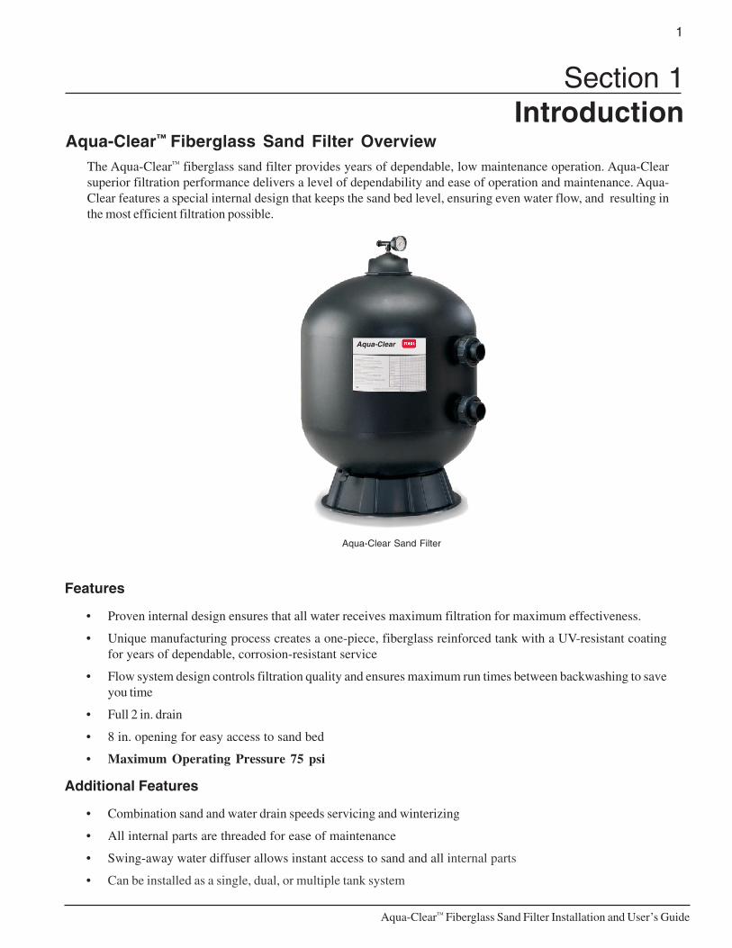
Aqua-Clear™ Fiberglass Sand Filter OverviewThe Aqua-Clear™ fiberglass sand filter provides years of dependable, low maintenance operation. Aqua-Clearsuperior filtration performance delivers a level of dependability and ease of operation and maintenance. Aqua-Clear features a special internal design that keeps the sand bed level, ensuring even water flow, and resulting inthe most efficient filtration possible.
Aqua-Clear Sand Filter
Features
• Proven internal design ensures that all water receives maximum filtration for maximum effectiveness.
• Unique manufacturing process creates a one-piece, fiberglass reinforced tank with a UV-resistant coatingfor years of dependable, corrosion-resistant service
• Flow system design controls filtration quality and ensures maximum run times between backwashing to saveyou time
• Full 2 in. drain
• 8 in. opening for easy access to sand bed
• Maximum Operating Pressure 75 psi
Additional Features
• Combination sand and water drain speeds servicing and winterizing
• All internal parts are threaded for ease of maintenance
• Swing-away water diffuser allows instant access to sand and all internal parts
• Can be installed as a single, dual, or multiple tank system
Aqua-Clear
2
Aqua-Clear™ Fiberglass Sand Filter Installation and User’s Guide
Section 2Installation
Note: Before installing this product, read and follow all warning and safety notices and instructionsstarting on page ii.
Installing the Aqua-Clear Fiberglass Sand FilterOnly a qualified service person should install the Aqua-Clear Fiberglass Sand Filter. This filter isdesigned and intended for use to filter water.
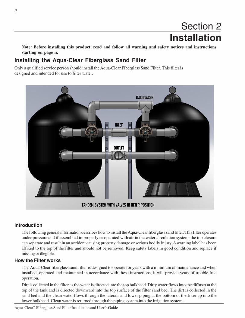
IntroductionThe following general information describes how to install the Aqua-Clear fiberglass sand filter. This filter operatesunder pressure and if assembled improperly or operated with air in the water circulation system, the top closurecan separate and result in an accident causing property damage or serious bodily injury. A warning label has beenaffixed to the top of the filter and should not be removed. Keep safety labels in good condition and replace ifmissing or illegible.
How the Filter worksThe Aqua-Clear fiberglass sand filter is designed to operate for years with a minimum of maintenance and wheninstalled, operated and maintained in accordance with these instructions, it will provide years of trouble freeoperation.
Dirt is collected in the filter as the water is directed into the top bulkhead. Dirty water flows into the diffuser at thetop of the tank and is directed downward into the top surface of the filter sand bed. The dirt is collected in thesand bed and the clean water flows through the laterals and lower piping at the bottom of the filter up into thelower bulkhead. Clean water is returned through the piping system into the irrigation system.
3
Aqua-Clear™ Fiberglass Sand Filter Installation and User’s Guide
WARNING — Failure to maintain and operate your filter system or inadequate filtration can result in clogging of theirrigation system and crop damage.
WARNING — Filters should never be tested or subjected to air or gas under pressure. All gases are compressibleand under pressure create a danger. Severe bodily injury or property damage could occur if the filteris subjected to air or gas pressure.
1. Check carton for any evidence of damage due to rough handling in shipment. If carton or any filter componentsare damaged, notify the freight carrier immediately.
2. Carefully remove the accessory package and the filter tank from the carton.
3. Mount the filter on a permanent slab, preferably concrete poured in a form or on a platform constructed ofconcrete block or brick. DO NOT use sand to level the filter or for the pump mounting, as it will wash away.
4. Provide space and lighting for routine maintenance access. Do not mount electrical controls over the filter. Oneneeds to be able to stand clear of the filter when starting the pump. Minimum space requirements may be foundon the large nameplate on the filter.
5. Position filter so that the port locations are in the desired final positions.
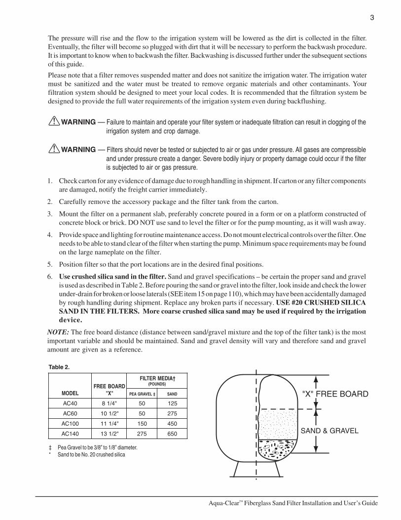
6. Use crushed silica sand in the filter. Sand and gravel specifications – be certain the proper sand and gravelis used as described in Table 2. Before pouring the sand or gravel into the filter, look inside and check the lowerunder-drain for broken or loose laterals (SEE item 15 on page 110), which may have been accidentally damagedby rough handling during shipment. Replace any broken parts if necessary. USE #20 CRUSHED SILICASAND IN THE FILTERS. More coarse crushed silica sand may be used if required by the irrigationdevice.
NOTE: The free board distance (distance between sand/gravel mixture and the top of the filter tank) is the mostimportant variable and should be maintained. Sand and gravel density will vary and therefore sand and gravelamount are given as a reference.
‡ Pea Gravel to be 3/8” to 1/8” diameter.* Sand to be No. 20 crushed silica
Table 2.
"X" FREE BOARD
SAND & GRAVEL
LEDOMDRAOBEERF
"X"
†AIDEMRETLIF)SDNUOP(
‡LEVARGAEP DNAS
04CA "4/18 05 521
06CA "2/101 05 572
001CA "4/111 051 054
041CA "2/131 572 056
The pressure will rise and the flow to the irrigation system will be lowered as the dirt is collected in the filter.Eventually, the filter will become so plugged with dirt that it will be necessary to perform the backwash procedure.It is important to know when to backwash the filter. Backwashing is discussed further under the subsequent sectionsof this guide.
Please note that a filter removes suspended matter and does not sanitize the irrigation water. The irrigation watermust be sanitized and the water must be treated to remove organic materials and other contaminants. Yourfiltration system should be designed to meet your local codes. It is recommended that the filtration system bedesigned to provide the full water requirements of the irrigation system even during backflushing.
4
Aqua-Clear™ Fiberglass Sand Filter Installation and User’s Guide
WARNING — Failure to position the Automatic Air Vent inside of the Closure will allow excessive trapped air toaccumulate in the filter. If the Closure is properly closed, trapped air can cause the Closure toseparate and could cause severe bodily injury and/or property damage.
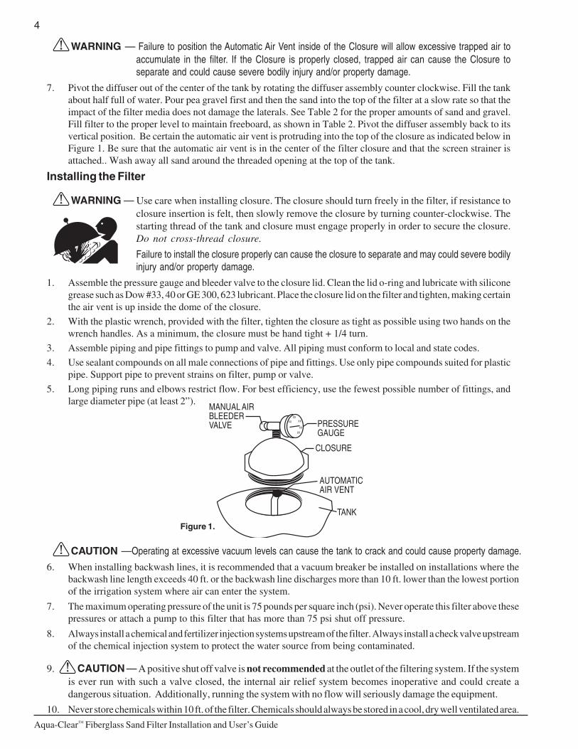
7. Pivot the diffuser out of the center of the tank by rotating the diffuser assembly counter clockwise. Fill the tankabout half full of water. Pour pea gravel first and then the sand into the top of the filter at a slow rate so that theimpact of the filter media does not damage the laterals. See Table 2 for the proper amounts of sand and gravel.Fill filter to the proper level to maintain freeboard, as shown in Table 2. Pivot the diffuser assembly back to itsvertical position. Be certain the automatic air vent is protruding into the top of the closure as indicated below inFigure 1. Be sure that the automatic air vent is in the center of the filter closure and that the screen strainer isattached.. Wash away all sand around the threaded opening at the top of the tank.
Installing the Filter
WARNING — Use care when installing closure. The closure should turn freely in the filter, if resistance toclosure insertion is felt, then slowly remove the closure by turning counter-clockwise. Thestarting thread of the tank and closure must engage properly in order to secure the closure.Do not cross-thread closure.
Failure to install the closure properly can cause the closure to separate and may could severe bodilyinjury and/or property damage.
1. Assemble the pressure gauge and bleeder valve to the closure lid. Clean the lid o-ring and lubricate with siliconegrease such as Dow #33, 40 or GE 300, 623 lubricant. Place the closure lid on the filter and tighten, making certainthe air vent is up inside the dome of the closure.
2. With the plastic wrench, provided with the filter, tighten the closure as tight as possible using two hands on thewrench handles. As a minimum, the closure must be hand tight + 1/4 turn.
3. Assemble piping and pipe fittings to pump and valve. All piping must conform to local and state codes.
4. Use sealant compounds on all male connections of pipe and fittings. Use only pipe compounds suited for plasticpipe. Support pipe to prevent strains on filter, pump or valve.
5. Long piping runs and elbows restrict flow. For best efficiency, use the fewest possible number of fittings, andlarge diameter pipe (at least 2”).
Figure 1.
MANUAL AIRBLEEDERVALVE PRESSURE
GAUGE
CLOSURE
TANK
AUTOMATICAIR VENT
XX
XXXX
XX
XX
CAUTION —Operating at excessive vacuum levels can cause the tank to crack and could cause property damage.
6. When installing backwash lines, it is recommended that a vacuum breaker be installed on installations where thebackwash line length exceeds 40 ft. or the backwash line discharges more than 10 ft. lower than the lowest portionof the irrigation system where air can enter the system.
7. The maximum operating pressure of the unit is 75 pounds per square inch (psi). Never operate this filter above thesepressures or attach a pump to this filter that has more than 75 psi shut off pressure.
8. Always install a chemical and fertilizer injection systems upstream of the filter. Always install a check valve upstreamof the chemical injection system to protect the water source from being contaminated.
9. CAUTION — A positive shut off valve is not recommended at the outlet of the filtering system. If the systemis ever run with such a valve closed, the internal air relief system becomes inoperative and could create adangerous situation. Additionally, running the system with no flow will seriously damage the equipment.
10. Never store chemicals within 10 ft. of the filter. Chemicals should always be stored in a cool, dry well ventilated area.
5
Aqua-Clear™ Fiberglass Sand Filter Installation and User’s Guide
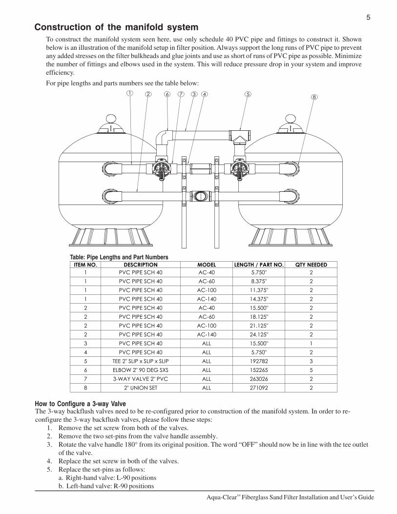
Construction of the manifold systemTo construct the manifold system seen here, use only schedule 40 PVC pipe and fittings to construct it. Shownbelow is an illustration of the manifold setup in filter position. Always support the long runs of PVC pipe to preventany added stresses on the filter bulkheads and glue joints and use as short of runs of PVC pipe as possible. Minimizethe number of fittings and elbows used in the system. This will reduce pressure drop in your system and improveefficiency.
For pipe lengths and parts numbers see the table below:
47 36 51 2 8
DEDEEN YTQ.ON TRAP / HTGNELLEDOMNOITPIRCSED.ON METI2"057.504-CA04 HCS EPIP CVP12"573.806-CA04 HCS EPIP CVP12"573.11001-CA04 HCS EPIP CVP12"573.41041-CA04 HCS EPIP CVP12"005.5104-CA04 HCS EPIP CVP22"521.8106-CA04 HCS EPIP CVP22"521.12001-CA04 HCS EPIP CVP22"521.42041-CA04 HCS EPIP CVP21"005.51LLA04 HCS EPIP CVP32"057.5LLA04 HCS EPIP CVP43287291LLAPILS x PILS x PILS "2 EET55562251LLASXS GED 09 "2 WOBLE62620362LLACVP "2 EVLAV YAW-372290172LLATES NOINU "28
The 3-way backflush valves need to be re-configured prior to construction of the manifold system. In order to re-configure the 3-way backflush valves, please follow these steps:
1. Remove the set screw from both of the valves.2. Remove the two set-pins from the valve handle assembly.3. Rotate the valve handle 180° from its original position. The word “OFF” should now be in line with the tee outlet
of the valve.4. Replace the set screw in both of the valves.5. Replace the set-pins as follows:
a. Right-hand valve: L-90 positionsb. Left-hand valve: R-90 positions
Table: Pipe Lengths and Part Numbers
How to Configure a 3-way Valve
6
Aqua-Clear™ Fiberglass Sand Filter Installation and User’s Guide
Initial Start-up1. Connect the water source to the filter, but do not connect the filter to the downstream irrigation system until the
filter sand has been adequately cleaned. Always backflush the filter immediately upon start up to removeout the small particles that are in the sand. If you start the system without cleaning the sand, the initial flow ofthese small particles into the irrigation system can cause clogging.
2. Be sure the backwash line is open so that water is free to flow out the backwash line. Set the valve or the manifoldto the BACKWASH position.
WARNING — If the tank closure not installed properly, air entering the filter can cause the closure to separate andcould cause severe bodily injury and/or property damage.
3. Check closure on filter for tightness.
4. Open the manual air bleeder on the filter closure. Stand clear of the filter and start the pump allowing it to prime.
5. Close the air bleeder on the closure when all the air is removed from the filter and a steady stream of water emerges.
NOTE: Irrigation filter sand is typically not pre-washed and requires an extended backwash cycle at initialstart-up; continue to backwash until the backwash water is clear.
WARNING — To prevent equipment damage and possible injury, always turn the pump off before changing the valveposition.
6. Stop the pump. Set the valve or the manifold to the FILTER position.
7. Ensure at least one zone valve is open so that water is free to flow to the irrigation system.
8. Open the manual air bleeder on the filter closure. Stand clear of the filter and start the pump.
9. Close the air bleeder on the filter closure when all the air is removed from the filter and a steady stream of water emerges.
10. The filter has now started its filtering cycle. You should ensure that water is flowing to the irrigation system and takenote of the operating pressure when the filter is clean.
WARNING — Wash the pea gravel before it is inserted into the tank.
WARNING — For dual tank systems, only one valve should be in backflush position at a time.
7
Aqua-Clear™ Fiberglass Sand Filter Installation and User’s Guide
Section 3Maintenance
This section describes how to maintain your Aqua-Clear Fiberglass Sand Filter.
Filter CareThe filter is a very important part of the system equipment and installation. Proper care and maintenance will addmany years of service to the system. Follow these suggestions for long trouble-free operations:
1. To clean the exterior of the filter of dust and dirt, wash with a mild detergent and water then hose off. Do notuse solvents.
2. If internal maintenance is required, sand may be removed by removing the sand drain from the bottom of the filterand flushing with a garden hose.
3. If after a number of years, the filter tank appears foggy in color or rough in texture, the tank surface can bepainted. We recommend the use of a Quick Dry Spray Enamel. Do NOT paint the valve.
WARNING — Always visually inspect filter components during normal servicing to ensure structural safety. Replaceany item which is cracked, deformed or otherwise visually defective. Defective filter components canallow the filter top or attachments to blow off and could cause severe bodily injury or propertydamage.
4. The filter closure on your Aqua-Clear Sand Filter was manufactured with high quality corrosion resistant materials. This part should be carefully inspected whenever servicing your filter. If excessive leakage is noted coming from the closure/tank interface, the closure and o-ring should be carefully inspected and replaced if any signs of deterioration exist.
5. Your filter is a pressure vessel and should never be serviced while under pressure. Always relieve tank pressureand open air bleeder on the filter closure before attempting to service your filter.
6. When restarting your filter, always open the manual air bleeder on the filter closure and stand clear of the filter.
Cleaning1. The filter should be backwashed when one of the following conditions is met:
a. A second pressure gauge, installed downstream of the filter, should be compared to the pressure gaugelocated on the filter tank. The downstream pressure gauge should read a lower pressure under normalconditions due to pressure lost in the filter. If this normal pressure differential increases 6 lbs., the filtershould be backwashed.
3. In addition, the filter should be backwashed on a regular basis depending on need. In order to determine theminimum frequency of backwashing, start backwashing after every 8 hours of operation. If the backwashwater is clear, then the frequency can be extended. Keep in mind that factors like weather conditions, heavyrains, algae blooms, groundwater levels and water temperature all affect the frequency of backwash. As youuse your irrigation system, you will become aware of these influences.
4. If at any time the starting pressure after backwashing the filter indicates 4 to 6 PSI higher than normal startingpressure, inspect the sand for chemical or physical changes from its original condition. Raking of the sand orreplacement of the sand may be required.
Filter Procedure (see diagram on page 8)
1. Turn pump OFF.
2. Handles of the 3-way valves are to be set vertically (straight up and down)
3. Lock the handles in place by using the thumb screw lock
4. Note: Water enters the PVC tee located between the two 3-way valves. Water outlet to the field exits fromthe threaded PVC tee located on the bottom manifold
5. Note: If water comes out of the upper manifold you are backflushing, not filtering. Turn the 3-way valve sothat the word "OFF" is at the top of the 3-way valve.
8
Aqua-Clear™ Fiberglass Sand Filter Installation and User’s Guide
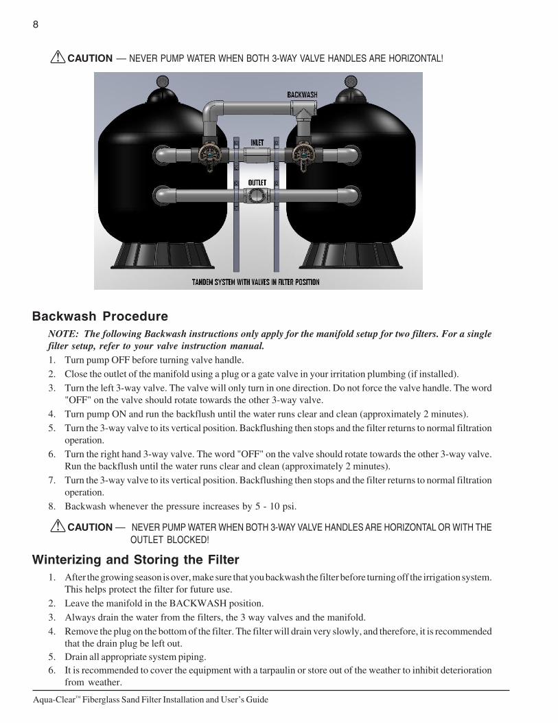
CAUTION — NEVER PUMP WATER WHEN BOTH 3-WAY VALVE HANDLES ARE HORIZONTAL!
Backwash ProcedureNOTE: The following Backwash instructions only apply for the manifold setup for two filters. For a singlefilter setup, refer to your valve instruction manual.1. Turn pump OFF before turning valve handle.
2. Close the outlet of the manifold using a plug or a gate valve in your irritation plumbing (if installed).3. Turn the left 3-way valve. The valve will only turn in one direction. Do not force the valve handle. The word
"OFF" on the valve should rotate towards the other 3-way valve.
4. Turn pump ON and run the backflush until the water runs clear and clean (approximately 2 minutes).
5. Turn the 3-way valve to its vertical position. Backflushing then stops and the filter returns to normal filtrationoperation.
6. Turn the right hand 3-way valve. The word "OFF" on the valve should rotate towards the other 3-way valve.Run the backflush until the water runs clear and clean (approximately 2 minutes).
7. Turn the 3-way valve to its vertical position. Backflushing then stops and the filter returns to normal filtrationoperation.
8. Backwash whenever the pressure increases by 5 - 10 psi.
CAUTION — NEVER PUMP WATER WHEN BOTH 3-WAY VALVE HANDLES ARE HORIZONTAL OR WITH THEOUTLET BLOCKED!
Winterizing and Storing the Filter1. After the growing season is over, make sure that you backwash the filter before turning off the irrigation system.
This helps protect the filter for future use.
2. Leave the manifold in the BACKWASH position.
3. Always drain the water from the filters, the 3 way valves and the manifold.
4. Remove the plug on the bottom of the filter. The filter will drain very slowly, and therefore, it is recommendedthat the drain plug be left out.
5. Drain all appropriate system piping.6. It is recommended to cover the equipment with a tarpaulin or store out of the weather to inhibit deterioration
from weather.
9
Aqua-Clear™ Fiberglass Sand Filter Installation and User’s Guide
Section 4Troubleshooting
Use the following troubleshooting information to resolve possible problems with your filter.
WARNING — THIS FILTER OPERATES UNDER HIGH PRESSUREWhen any part of the circulating system, (e.g., closure, pump, filter, valve(s), etc.), is serviced, air canenter the system and become pressurized. Pressurized air can cause the top closure to separate whichcan result in severe injury, death, or property damage. To avoid this potential hazard, follow theseinstructions:
1. If you are not familiar with your filtering system:
a. Do NOT attempt to adjust or service without consulting your dealer, or a qualified technician.
b. Read the entire Installation & User’s Guide before attempting to use, service or adjust thefiltering system.
2. Before repositioning valve(s) and before beginning the assembly, disassembly, or any otherservice of the filter system: (A) Turn the pump OFF and shut OFF any automatic controlsto ensure the system is NOT inadvertently started during the servicing; (B) open the manual airbleeder valve; (C) wait until all pressure is relieved.
3. Whenever installing the filter closure FOLLOW THE FILTER CLOSURE WARNINGS EXACTLY.
4. Once service on the irrigation system is complete FOLLOW INITIAL START-UP INSTRUCTIONSEXACTLY.
5. Maintain irrigation system properly. Replace worn or damaged parts immediately, (e.g., closure,pressure gauge, valve(s), o-rings, etc.).
6. Be sure that the filter is properly mounted and positioned according to instructions provided.
Note: Turn off power to unit prior to attempting service or repair.
Problems and Corrective Actions
PROBLEM CAUSE REMEDY
irrigation water not sufficiently clean 1. Break in the line. Repair breaks in system and flush all dirt from systemprior to restarting the system.
2. Too frequent a backwash cycle. Add additional tanks to increase filtration capacitybetween backflush cycles.
3. Improper amount or wrong sand size. Check sand bed Freeboard and sand size orconsult a service technician.
4. Channeling of sand allows dirty water Rake the sand and consult your dealer to determine thedownstream of the filter. cause of channeling.
5. Air strainer is damaged or missing. Replace damaged components.
High filter pressure 1. Insufficient backwashing. Backwash until effluent runs clear.
2. Sand bed plugged with mineral deposits. Rake or replace sand.
3. Partially closed valve. Open valve or remove obstruction in return line.
Short cycles between cleaning 1. Improper backwash. Backwash until effluent runs clear.
2. Exceptionally dirty water. Install additional tanks to increase filtration capacity.
3. Plugged sand bed. Manually remove top 1” surface of sand bed,replace with new sand.
4. Flow rate too high. Install additional tanks to increase filtration capacity.
10
Aqua-Clear™ Fiberglass Sand Filter Installation and User’s Guide
Flow to system diminished. 1. Break in line. Repair line and flush the system before restart.
2. Filter needs to be cleaned Backflush filter according to directions
3. Valve is closed Check pressures and valve settings.
Sand in irrigation lines 1. Broken under drain lateral. Replace broken or damaged laterals.
Sand loss to waste 1. Backwash rate too high. Reduce backwash flow rate.
2. Improper sand size. Change to proper sand.
3. Air strainer is damaged or missing. Replace damage components.
Leak at closure 1. Improperly tightened closure. Shut off pump, relieve tank pressure,open air bleeder, tighten closure properly.
2. Dirt or contamination on sealing surface. Shut off pump, relieve tank pressure, openair bleeder, remove closure and clean all sealingsurfaces. Reassemble closure properly.
3. Damaged part. Same as above except replace damaged o-ring,closure, tank or any combination of parts as required.
Leak at bulkhead 1. Improper tightened bulkhead assembly. Shut off pump, relieve tank pressure, open air bleeder,remove closure and remove sand to access leakingbulkhead. Hold the 2” bulkhead and tighten the2” internal locknut. Hand tighten plus 1/2 turn.
2. Dirt or contamination on sealing surfaces. Shut off pump, relieve tank pressure, openair bleeder, remove closure and remove sand toaccess leaking bulkhead. Remove attached tankinternals and remove bulkhead assembly. Clean allmating surfaces and seals. Replace the bulkheadassembly, being careful to assemble properly.Tighten assembly as indicated above.
3. Damaged part. Same as above except replace damaged part orcombination of parts.
PROBLEM CAUSE REMEDY
11
Aqua-Clear™ Fiberglass Sand Filter Installation and User’s Guide
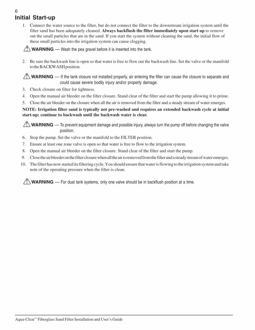
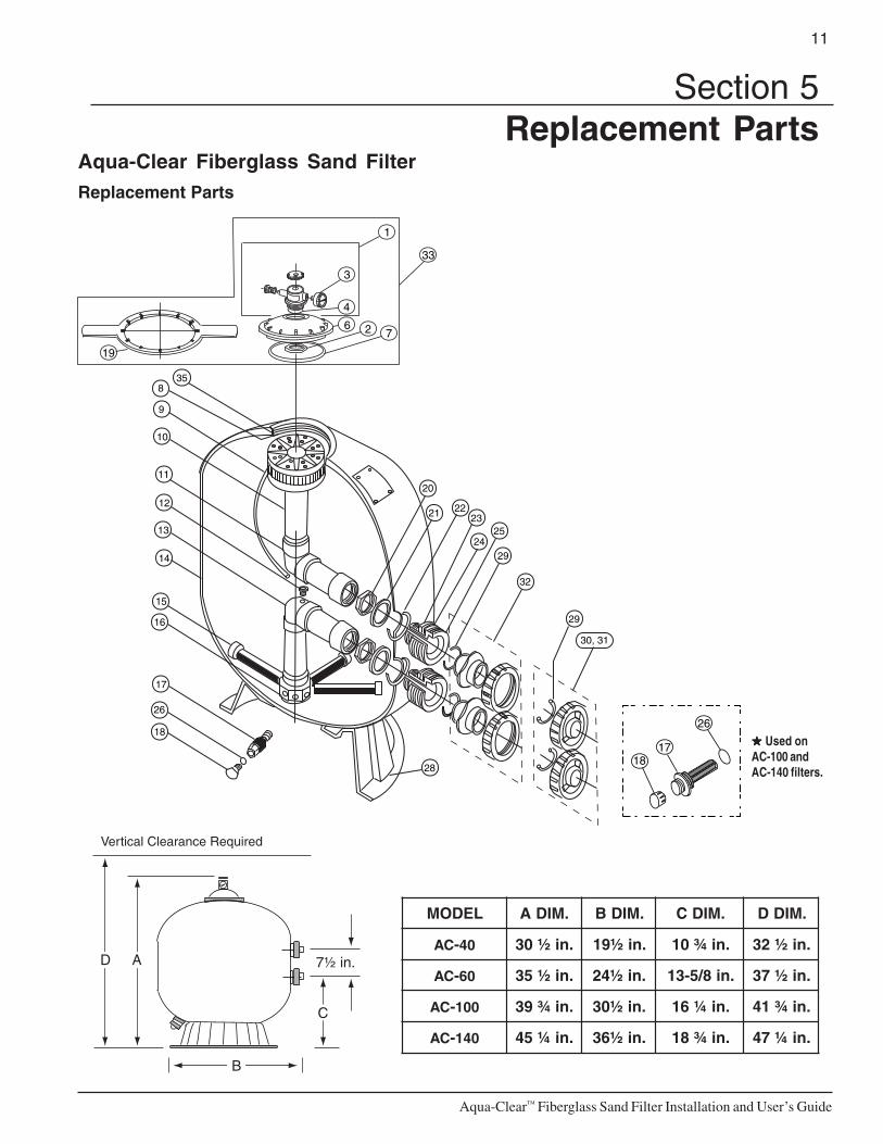
Aqua-Clear Fiberglass Sand FilterReplacement Parts
20
21 22
24
2325
29
32
29
30, 31
28
17
18
26
14
16
15
11
13
12
10
9
835
2 76
4
3
1
19
33
18
26
17 ★★★★★ Used onAC-100 andAC-140 filters.
LEDOM .MIDA .MIDB .MIDC .MIDD
CA - 04 .ni½03 .ni½91 .ni¾01 .ni½23
CA - 06 .ni½53 .ni½42 .ni8/5-31 .ni½73
CA - 001 .ni¾93 .ni½03 .ni¼61 .ni¾14
CA - 041 .ni¼54 .ni½63 .ni¾81 .ni¼74
Section 5Replacement Parts
12
Aqua-Clear™ Fiberglass Sand Filter Installation and User’s Guide
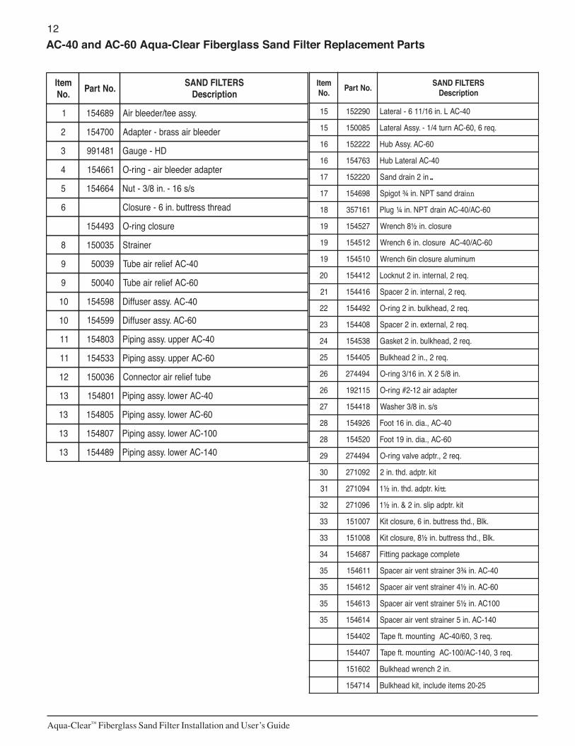
AC-40 and AC-60 Aqua-Clear Fiberglass Sand Filter Replacement Parts
metI.oN .oNtraP SRETLIFDNAS
noitpircseD
1 986451 .yssaeet/redeelbriA
2 007451 redeelbriassarb-retpadA
3 184199 DH-eguaG
4 166451 retpadaredeelbria-gnir-O
5 466451 s/s61-.ni8/3-tuN
6 daerhtsserttub.ni6-erusolC
394451 erusolcgnir-O
8 530051 reniartS
9 93005 AC-40feilerriaebuT
9 04005 AC-60feilerriaebuT
01 89545 .yssaresuffiD
01 99545 C-60A.yssaresuffiD
11 308451 04-CAreppu.yssagnipiP
11 335451 06-CAreppu.yssagnipiP
21 630051 ebutfeilerriarotcennoC
31 108451 04-CArewol.yssagnipiP
31 508451 06-CArewol.yssagnipiP
31 708451 001-CArewol.yssagnipiP
31 984451 041-CArewol.yssagnipiP
metI.oN .oNtraP SRETLIFDNAS
noitpircseD
51 092251 04-CAL.ni61/116-laretaL
51 580051 .qer6,06-CAnrut4/1-.yssAlaretaL
61 222251 06-CA.yssAbuH
61 367451 04-CAlaretaLbuH
71 022251 ni2niarddnaS ..
71 896451 iarddnasTPN.ni¾togipS nn
81 161753 06-CA/04-CAniardTPN.ni¼gulP
91 725451 erusolc.ni½8hcnerW
91 215451 06-CA/04-CAerusolc.ni6hcnerW
91 015451 munimulaerusolcni6hcnerW
02 214451 .qer2,lanretni.ni2tunkcoL
12 614451 .qer2,lanretni.ni2recapS
22 294451 .qer2,daehklub.ni2gnir-O
32 804451 .qer2,lanretxe.ni2recapS
42 835451 .qer2,daehklub.ni2teksaG
52 504451 .qer2,.ni2daehkluB
62 494472 .ni8/52X.ni61/3gnir-O
62 511291 retpadaria21-2#gnir-O
72 814451 s/s.ni8/3rehsaW
82 629451 04-CA,.aid.ni61tooF
82 025451 06-CA,.aid.ni91tooF
92 494472 .qer2,.rtpdaevlavgnir-O
03 290172 tik.rtpda.dht.ni2
13 490172 ik.rtpda.dht.ni½1 tt
23 690172 tik.rtpdapils.ni2&.ni½1
33 700151 .klB,.dhtsserttub.ni6,erusolctiK
33 800151 .klB,.dhtsserttub.ni½8,erusolctiK
43 786451 etelpmocegakcapgnittiF
53 116451 04-CA.ni¾3reniartstnevriarecapS
53 216451 06-CA.ni½4reniartstnevriarecapS
53 316451 001CA.ni½5reniartstnevriarecapS
53 416451 041-CA.ni5reniartstnevriarecapS
204451 .qer3,06/04-CAgnitnuom.tfepaT
704451 .qer3,041-CA/001-CAgnitnuom.tfepaT
206151 .ni2hcnerwdaehkluB
417451 52-02smetiedulcni,tikdaehkluB
AC-401
1

13
Aqua-Clear™ Fiberglass Sand Filter Installation and User’s Guide
AC-100 and AC-140 Aqua-Clear Fiberglass Sand Filter Replacement Parts
metI.oN
.oNtraPSRETLIFDNAS
noitpircseD
1 465372 .yssaydobfeilerrialaunaM
3 050551 eguagerusserP
2 214451 lanretni.ni2tuN
4 494472 ..d.i.ni8/5-2X.ni61/3gnir-O
6 575451 sserttub.ni½8erusolC
7 905251 .ni½8gnirerauqS
9 140051 001-CAfeilerriaebuT
9 240051 041-CAfeilerriaebuT
01 264451 001-CA.yssaresuffiD
01 609451 041-CA.yssaresuffiD
11 624451 001-CAreppu.yssagnipiP
11 005451 041-CAreppu.yssagnipiP
51 045451 .qer8,041-CAL.ni21-laretaL
51 202251 .qer8,001-CAL.ni8/19-laretaL
61 354451 laretaLbuH
81 178451 .ni½1.dhtpaC
91 806151 munimulaerusolc.ni½8hcnerW
91 725451 erusolc.ni½8hcnerW
82 695451 041-CA/001-CA,.aid.ni42tooF
73 690172roftikretpadapilsni2&ni2/11
)riap(evlavo/w.tsni

P/N 151002 Rev. A 02/25/11
*151200*